JP4638923B2 - Control device - Google Patents
Control deviceDownload PDFInfo
- Publication number
- JP4638923B2 JP4638923B2JP2008091580AJP2008091580AJP4638923B2JP 4638923 B2JP4638923 B2JP 4638923B2JP 2008091580 AJP2008091580 AJP 2008091580AJP 2008091580 AJP2008091580 AJP 2008091580AJP 4638923 B2JP4638923 B2JP 4638923B2
- Authority
- JP
- Japan
- Prior art keywords
- control device
- housing cover
- retract
- heat
- control board
- Prior art date
- Legal status (The legal status is an assumption and is not a legal conclusion. Google has not performed a legal analysis and makes no representation as to the accuracy of the status listed.)
- Expired - Fee Related
Links
Images


Classifications
- H—ELECTRICITY
- H05—ELECTRIC TECHNIQUES NOT OTHERWISE PROVIDED FOR
- H05K—PRINTED CIRCUITS; CASINGS OR CONSTRUCTIONAL DETAILS OF ELECTRIC APPARATUS; MANUFACTURE OF ASSEMBLAGES OF ELECTRICAL COMPONENTS
- H05K7/00—Constructional details common to different types of electric apparatus
- H05K7/02—Arrangements of circuit components or wiring on supporting structure
- H05K7/026—Multiple connections subassemblies
- H—ELECTRICITY
- H05—ELECTRIC TECHNIQUES NOT OTHERWISE PROVIDED FOR
- H05K—PRINTED CIRCUITS; CASINGS OR CONSTRUCTIONAL DETAILS OF ELECTRIC APPARATUS; MANUFACTURE OF ASSEMBLAGES OF ELECTRICAL COMPONENTS
- H05K7/00—Constructional details common to different types of electric apparatus
- H05K7/20—Modifications to facilitate cooling, ventilating, or heating
- H05K7/20845—Modifications to facilitate cooling, ventilating, or heating for automotive electronic casings
- H05K7/20854—Heat transfer by conduction from internal heat source to heat radiating structure
Landscapes
- Engineering & Computer Science (AREA)
- Microelectronics & Electronic Packaging (AREA)
- Physics & Mathematics (AREA)
- Thermal Sciences (AREA)
- Cooling Or The Like Of Electrical Apparatus (AREA)
- Adhesives Or Adhesive Processes (AREA)
- Combinations Of Printed Boards (AREA)
Description
Translated fromJapanese本発明は、自動車等の車両に搭載される制御装置に係り、特に、コイル、コンデンサ等の発熱を伴う電子部品を搭載した制御装置の放熱構造に関する。 The present invention relates to a control device mounted on a vehicle such as an automobile, and more particularly to a heat dissipation structure of a control device mounted with electronic components that generate heat such as coils and capacitors.
自動車に搭載される制御装置は、近年、高出力化、高機能化の傾向にある。高出力化及び高機能化に対応するために、コイルやコンデンサ等の電子部品をサブモジュール化することにより電子部品を低抵抗で配線した制御装置がある。 In recent years, control devices mounted on automobiles tend to have higher output and higher functionality. In order to cope with higher output and higher functionality, there is a control device in which electronic components such as coils and capacitors are sub-moduleed to wire electronic components with low resistance.
図5は、従来の制御装置を示す分解斜視図である。図5に示すように、従来の制御装置は、マイクロコンピュータ等の回路を実装した制御基板1と、配線層(図示せず)を内蔵する樹脂ケース6にコイル8及びコンデンサ等の電子部品を実装したサブモジュール2と、制御基板1及びサブモジュール2を収容するハウジングカバー3とハウジングベース4とを備える。制御基板1とサブモジュール2とは電気的に接続され、かつ、ネジ等で機械的に固定されている。ハウジングカバー3の外面には放熱フィン16が設けられると共に、ハウジングカバー3とサブモジュール2との間には放熱シート13が介在する。電子部品はハウジングカバー3内側の平坦面に配置された低弾性の放熱シート13に押し当てられ、接触されることで、電子部品の発熱をハウジングカバー3に放熱している。 FIG. 5 is an exploded perspective view showing a conventional control device. As shown in FIG. 5, the conventional control device has electronic components such as a
放熱シートを用いた制御装置としては、放熱シートを介して回路基板上の発熱素子を外装枠体部の凹部に密着させた制御装置がある(例えば、特許文献1参照)。また、回路基板上の発熱素子を覆うように蓋体を取り付け、放熱用プレートが設けられた蓋体と発熱素子との間に放熱用のゲル材を充填した電子制御装置がある(例えば、特許文献2参照)。 As a control device using a heat radiating sheet, there is a control device in which a heating element on a circuit board is brought into close contact with a recess of an exterior frame body part via a heat radiating sheet (see, for example, Patent Document 1). In addition, there is an electronic control device in which a cover is attached so as to cover a heat generating element on a circuit board, and a heat dissipation element is filled with a gel material for heat dissipation between the cover provided with a heat dissipation plate and the heat generating element (for example, patents) Reference 2).
サブモジュールのコイルやコンデンサ等の電子部品は発熱を伴うことがある。しかしながら、図5に示した従来の制御装置ように、放熱シートを用いた放熱構造では、電子部品の寸法精度の観点から、電子部品とハウジングカバー間に挿入できる放熱シートの厚さが制限される。また、放熱シートの厚さを挿入可能な厚さに収めて放熱シートを挿入しても、放熱シートの反発力が電子部品を押圧することにより、電子部品に悪影響を及ぼすおそれがある。 Electronic components such as sub-module coils and capacitors may generate heat. However, as in the conventional control device shown in FIG. 5, in the heat dissipation structure using the heat dissipation sheet, the thickness of the heat dissipation sheet that can be inserted between the electronic component and the housing cover is limited from the viewpoint of the dimensional accuracy of the electronic component. . Further, even if the heat dissipation sheet is inserted to a thickness that allows the heat dissipation sheet to be inserted, the repulsive force of the heat dissipation sheet may press the electronic component, which may adversely affect the electronic component.
特に、コイルやコンデンサ等、形状の異なる電子部品を実装したサブモジュールをハウジングカバー内に収容する制御装置では、実装された各電子部品に過剰な反発力を付与することなく電子部品が放熱シートとの接触面積を十分に確保することができなかった。 In particular, in a control device that accommodates submodules mounted with electronic parts of different shapes, such as coils and capacitors, in the housing cover, the electronic parts are connected to the heat dissipation sheet without applying excessive repulsive force to each mounted electronic part. It was not possible to ensure a sufficient contact area.
本発明の目的は、上記課題を解決すべく、サブモジュールに取り付けられた電子部品の放熱面積を大きくし、サブモジュールの放熱性を向上させた制御装置を提供することにある。 In order to solve the above problems, an object of the present invention is to provide a control device in which the heat dissipation area of an electronic component attached to a submodule is increased and the heat dissipation of the submodule is improved.
上記目的を達成すべく本発明に係る制御装置は、例えば、制御基板と、形状の異なる第1及び第2の電子部品を有し、前記制御基板と電気的に接続されたモジュールケースと、前記制御基板と前記モジュールケースとを覆うハウジングカバーと、を備えた制御装置において、前記モジュールケースは開口部を有し、放熱板が前記開口部に設けられ、かつ、前記放熱板は前記制御基板上に設けられており、前記ハウジングカバーは、前記第1の電子部品の形状に相対する形状の第1の収納部と、前記第2の電子部品の形状に相対する形状の第2の収納部とを有し、
前記放熱板は、前記第1の電子部品の形状に相対する形状の第3の収納部を有し、
前記第1の電子部品は、前記第1の収納部と前記第3の収納部との間に配置され、
前記第2の電子部品は、前記第2の収納部と前記モジュールケースとの間に配置され、
前記第1の収納部と前記第1の電子部品との間、前記第2の収納部と前記第2の電子部品との間、前記第3の収納部と前記第1の電子部品との間にそれぞれ放熱接着剤が充填されているように構成する。In order to achieve the above object, a control device according to the present invention includes, for example, a control board, a module case having first and second electronic components having different shapes, and electrically connected to the control board,And a housing coverthat covers the control board and the module case, wherein the module case has an opening, a heat sink is provided in the opening, and the heat sink is disposed on the control board. Thehousing cover includes a first storage portion having a shape corresponding to the shape of the first electronic component, and a second storage portion having a shape corresponding to the shape of the second electronic component. Have
The heat radiating plate has a third storage portion having a shape opposite to the shape of the first electronic component,
The first electronic component is disposed between the first storage unit and the third storage unit,
The second electronic component is disposed between the second storage unit and the module case,
Between the first storage part and the first electronic component, between the second storage part and the second electronic component, and between the third storage part and the first electronic component. Each of them is filled with a heat radiation adhesive.
本発明によれば、サブモジュールに取り付けられた電子部品の放熱面積を大きくし、サブモジュールの放熱性を向上させることができる。 ADVANTAGE OF THE INVENTION According to this invention, the thermal radiation area of the electronic component attached to the submodule can be enlarged, and the heat dissipation of a submodule can be improved.
以下、本発明に関連する参考例と本発明の好適な実施形態を添付図面に基づいて説明する。Hereinafter,reference examples related to the present invention and preferred embodiments of the present inventionwill be describedwith reference to the accompanying drawings.
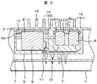
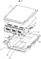
図1は、本発明に関連する参考例の制御装置を示す分解斜視図である。図2は、図1の制御装置の分解斜視図である。図3は、図2の制御装置のA−A線拡大断面図である。ただし、図2は図1及び3に対して上下逆に表示されている。FIG. 1 is an exploded perspective view showinga control device ofa reference example related to thepresent invention . FIG. 2 is an exploded perspective view of the control device of FIG. 3 is an enlarged cross-sectional view taken along line AA of the control device of FIG. However, FIG. 2 is displayed upside down with respect to FIGS.
図1〜図3に示すように、制御装置は、マイクロコンピュータなどのチップ(素子)や外部インターフェースであるコネクタ5とを実装した制御基板1と、モジュールケース6に電子部品8,9を実装したサブモジュール2と、制御基板1及びサブモジュール2を収容するハウジングカバー3とハウジングベース4とを備える。 As shown in FIGS. 1 to 3, the control device has
制御装置は、サブモジュール2がハウジングカバー3内のスペースに収容されて固定され、制御基板1もハウジングカバー3に固定され、制御基板1とサブモジュール2とを固定したハウジングカバー3とハウジングベース4とが互いに締結固定された構造となっている。 In the control device, the
サブモジュール2は、電子部品としてコイル8とコンデンサ9を樹脂製のモジュールケース(以下「樹脂ケース」という)6に収納したLCモジュールである。本参考例では、サブモジュール2は、横円柱状のコンデンサ9を3つ、縦円筒状のコイル8を2つ備え、制御装置は、2つのサブモジュール2を備える。電子部品8,9は、樹脂ケース6の一面から露出した状態で突出している。サブモジュールのコイル8及びコンデンサ9は、例えば、車両のバッテリ電源を昇圧し、昇圧電圧をアクチュエータに供給する昇圧回路の一部を構成する。樹脂ケース6は、その内部に配線層7を備える。配線層7は、樹脂ケース6内のコイル8及びコンデンサ9と、制御基板1とを電気的に接続するためのパターンを有する金属層である。コンデンサ9(コイル8)と配線層7とは、コンデンサ9(コイル8)のリード線11を介して接続される。コイル8及びコンデンサ9と配線層7との接続は、コイル8及びコンデンサ9のリード線11を配線層7が臨む樹脂ケース6の穴に挿入し、Sn−Cuはんだ、Sn−Ag−Cuはんだ、Sn−Ag−Cu−Biはんだ等の鉛フリーはんだを用いて接続した。コイル8やコンデンサ9等の電子部品と配線層7との接続は、溶接を用いてもよい。また、樹脂ケース6には、配線層7と制御基板1とを電気的接続するための外部端子10が設けられる。配線層7を内部に備えた樹脂ケース6は、厚銅板材をプレス加工により製作した配線層7を耐熱性樹脂にインサート成形して形成される。厚銅板の配線層7を用いたサブモジュール2は、制御基板1の回路配線に比べて非常に低配線抵抗な昇圧回路を構成することができる。The
ハウジングカバー3のサブモジュール2を搭載する内面には、コイル8、コンデンサ9と相対する形状の収納部15が形成されている。また、少なくとも内面に収納部15が位置するところのハウジングカバー外面には放熱フィン16が形成さている。本参考例では、ハウジングカバー3は、ダイカストで作製された鋳造物であるが、切削加工により作製してもよい。ハウジングカバー3を構成する材料は、高熱伝導性を有する金属材料であるのが好ましく、量産性、軽量化、放熱性の向上の観点から、アルミニウム、アルミニウム合金であるのがよい。他に、鉄等の金属を用いて構成してもよい。A
本参考例では、サブモジュール2が実装する2つのコイル8と3つのコンデンサ9の形状及び配置に合わせて個々に収納部が形成されている。具体的には、コイル8に相対する収納部151の形状は、円形の凹部である。コンデンサ9に相対する収納部152の形状は、略長方形の凹部である。ただし、その凹部の壁(横円柱状のコンデンサ9の側面にあたる側の壁)は、一部斜面153に形成されている。In thisreference example , storage portions are individually formed in accordance with the shapes and arrangements of the two
収納部15と電子部品8,9との間には放熱接着剤14が介在する。放熱接着剤14は、シリコーン樹脂にAl2O3等のフィラーを含有した熱硬化型樹脂或いは湿度硬化型樹脂である。放熱接着剤14は、その熱伝導率が0.5〜5(W/mK)であるのがよく、本参考例では約1(W/mK)のものを用いた。放熱接着剤の弾性率は、1〜1000(kPa)であるのがよく、少なくとも樹脂ケース6に実装されるコイル8及びコンデンサ9よりは低弾性であるのが好ましい。また、放熱接着剤の針入度は10〜50(1/10mm)であるのがよい。サブモジュール2に実装される電子部品8,9が、耐熱性の弱い部品である場合、湿度硬化型樹脂からなる放熱接着剤を用いるのがよい。A
サブモジュール2のハウジングカバー3への取り付けについては、まず、ハウジングカバー3の収納部15に硬化前(高粘性を有するゲル状)の放熱接着剤14を充填する。放熱接着剤14が充填された収納部15に、それぞれコイル8及びコンデンサ9を嵌め込む。その後、放熱接着剤14を硬化させ、サブモジュール2のサブモジュール側締結部21とハウジングカバー3の締結部31とをネジ等で締結固定する。このハウジングカバー締結部31は収納部15に対して高い位置(サブモジュール側に近い位置)に形成されており、ハウジングカバー締結部31とサブモジュール側締結部21とが当接すると、電子部品8,9と収納部15の底面とは接触することなく、かつ、電子部品8,9が放熱接着剤14に押し込まれて収納部15内に配置される。 Regarding the attachment of the
電子部品8,9が放熱接着剤14に押し込まれることにより、放熱接着剤14は、電子部品8,9の上面(ハウジングカバー3側の面)だけでなく、電子部品8,9の側面にも接触する。具体的には、コイル8の外側面の上部81及び内側面の上部82、コンデンサ9の円形面(円柱側面)の上部91及びコンデンサの平面部(円柱底面)の上部92にも放熱接着剤14が接触している。すなわち、コイル8及びコンデンサ9の上部が放熱接着剤中に埋め込まれている。電子部品8,9が放熱接着剤14に埋め込まれている面積(接触面積)は、電子部品の表面積の半分以下とする。 When the
サブモジュール2が固定されたハウジングカバー3には、制御基板1も固定される。具体的には、制御基板1がハウジングカバー3に搭載され、ネジ等を用いて機械的に締結固定される(制御基板のネジ穴41,ハウジングカバーのネジ穴32)。サブモジュール2の外部端子10と制御基板1のスルーホールとは、はんだを用いて接続される。はんだは、Sn−Cuはんだ、Sn−Ag−Cuはんだ、Sn−Ag−Cuはんだ、Sn−Ag−Cu−Biはんだ等の鉛フリーはんだを用いるのがよい。 The
制御装置は、ハウジングカバー3の開口を皿体のハウジングベース4で覆い、ハウジングカバー3の開口を閉塞した構造となっている。ハウジングベース4は、量産性、軽量化の向上の観点から、プレス加工によるめっき鋼板や、アルミ合金を用いて構成されるのがよい。また、ハウジングベース4は、耐熱性樹脂であるPET(Polyethylene Terephthalate)樹脂、PPS(Polyphenylene Sulfide)樹脂、或いはPBT(Polybutylene Terephthalate)樹脂製のハウジングベース4で構成されたものでもよい。これらの樹脂で形成されるハウジングベース4は、軽量で耐熱性に優れる。 The control device has a structure in which the opening of the
本参考例の制御装置によれば、ハウジングカバー3内面に電子部品8,9と相対する形状の収納部15を設けることで、電子部品8,9の放熱面積が広くなり、高放熱化できる。According to the control device of thisreference example , the heat radiation area of the
発熱を伴う電子部品8,9の放熱用の部材として放熱接着剤14を用い、ハウジングカバー3内面の収納部15に充填された放熱接着剤14中に、電子部品8,9の一部を埋め込む構造とすることで、従来の放熱シート13(図5参照)を用いた放熱構造と比較して、接触面積が15%大きくなり、高放熱化できる。 A
また、従来の放熱シート13を用いた放熱構造では、電子部品8,9の寸法精度の観点からシート厚みの設計が困難であったが、本参考例の制御装置の放熱構造のように電子部品8,9の一部を放熱接着剤14に埋め込む構造を採用することにより、電子部品8,9とハウジングカバー3間の隙間寸法を狭くして設計することができるため、更なる高放熱化が可能となる。In addition, in the conventional heat dissipation structure using the
本制御装置は、1つの電子部品8(9)ごとに個々に収納部14を設けていることにより、従来の放熱シート13を用いた制御装置に比して、放熱用の部材の充填量(使用量)を35%低減でき、低コスト化できる。 The present control device is provided with a
本制御装置は、電子部品8,9を放熱シート13に押し付ける構造ではなく、収納部15に充填した放熱接着剤14に接触した構造としているので、電子部品8,9には放熱シート13の押し付けによる反発力が作用せず、反発力による電子部品8,9の故障を防ぐことができる。また、電子部品8,9は、収納部15とその収納部15に充填された放熱接着剤14によりハウジングカバー3に固定されているため、耐振動性に優れる。 Since the present control device has a structure in which the
本制御装置は、制御基板1及びサブモジュール2がハウジングカバー3に機械的に締結固定された構造であるため、サブモジュール2を制御基板1に機械的に固定した従来の制御装置よりも耐振動性に優れる。さらに、制御基板1にはサブモジュール3を固定するための領域が不要となり、制御基板1の実装面積を大きくすることができる。 Since this control device has a structure in which the
次に、本発明の好適な実施形態について説明する。Next,a preferred embodiment of thepresent invention will be described.
図4は、本実施形態の制御装置の要部断面図である。図4に示すように、本実施形態の制御装置の基本的な構成部分は、上述した図1〜図3の制御装置とほぼ同様であり、同一構成部分には、図1に場合と同一の符号を付してある。ただし、本制御装置は、図2の制御装置において、さらにハウジングベース4側にも収納部18を形成し、サブモジュール2のコンデンサ9をハウジングカバー3側及びハウジングベース4側の両側から放熱する構造とした点において異なる。 FIG. 4 is a cross-sectional view of a main part of the control device of the present embodiment. As shown in FIG. 4, the basic components of the control device of the present embodiment are substantially the same as those of the control device of FIGS. 1 to 3 described above, and the same components are the same as in FIG. The code | symbol is attached | subjected. However, the present control device is similar to the control device shown in FIG. 2 in that a
本制御装置は、制御基板1とサブモジュール2との間に放熱板17が介在される。その放熱板17にはハウジングカバー3に形成された収納部15と同様に、収納部18が形成されている。樹脂ケース6のコンデンサ9の下方には、コンデンサ9が収納部18に臨むための開口部22が形成されている。放熱接着剤14は、ハウジングカバー3側の収納部15と、放熱板17側の収納部18の両方に充填される。また、制御基板1において、放熱板17が設けられた領域には、放熱用のビア(サーマルビア)19が形成されている。ビア19が形成された領域にあたるところのハウジングベース4外面には放熱フィン16が形成されている。 In the present control device, a
本実施形態の制御装置では、前参考例の制御装置の効果に加え、コンデンサ9で発した熱を、ハウジングベース4側とハウジングカバー3側との両方向から放熱させることができ、さらなる高放熱化を図ることができる。In the control device of this embodiment, in addition to the effect of the control device of the previousreference example , the heat generated by the capacitor 9 can be dissipated from both the
本実施形態では、樹脂ケース6のコンデンサ9の下方に開口部22を形成し、コンデンサ9を上下方向で放熱する構造としたが、この構造をコイル8側に適用してもよく、またコイル8及びコンデンサ9の両方に適用してもよい。 In the present embodiment, the
以上、本発明は、上述した実施の形態に限定されるものではなく、他にも種々のものが想定される。 As described above, the present invention is not limited to the above-described embodiments, and various other ones are assumed.
1 制御基板
2 サブモジュール
3 ハウジングカバー
4 ハウジングベース
6 樹脂ケース
7 配線層
8 コイル
9 コンデンサ
14 放熱接着剤
15 収納部
16 放熱フィンDESCRIPTION OF
Claims (11)
Translated fromJapanese形状の異なる第1及び第2の電子部品を有し、前記制御基板と電気的に接続されたモジュールケースと、
前記制御基板と前記モジュールケースとを覆うハウジングカバーと、を備えた制御装置において、
前記モジュールケースは開口部を有し、
放熱板が前記開口部に設けられ、かつ、前記放熱板は前記制御基板上に設けられており、
前記ハウジングカバーは、前記第1の電子部品の形状に相対する形状の第1の収納部と、前記第2の電子部品の形状に相対する形状の第2の収納部とを有し、
前記放熱板は、前記第1の電子部品の形状に相対する形状の第3の収納部を有し、
前記第1の電子部品は、前記第1の収納部と前記第3の収納部との間に配置され、
前記第2の電子部品は、前記第2の収納部と前記モジュールケースとの間に配置され、
前記第1の収納部と前記第1の電子部品との間、前記第2の収納部と前記第2の電子部品との間、前記第3の収納部と前記第1の電子部品との間にそれぞれ放熱接着剤が充填されていることを特徴とする制御装置。A control board;
A module case having first and second electronic components having different shapes and electrically connected to the control board;
In a control device comprising a housing cover that covers the control board and the module case,
The module case has an opening;
A heat sink is provided in the opening, and the heat sink is provided on the control board;
The housing cover has a firstretract and portions of the first shape on opposite shape of the electronic component, and a secondretract and part of the opposite shape to the shape of the second electronic component,
The radiator plate has a thirdretract and part of the opposite shape to the shape of the first electronic component,
Wherein the first electronic component is disposed between the firstretract and portion and the thirdretract and section,
The second electronic component is disposed between the secondretract and portion and the module case,
Wherein the firstretract and portion first between the electronic component, wherein between the secondretract and portion and the second electronic component, the thirdretract and portion and the first electronic component A control device characterized in that a heat-dissipating adhesive is filled between each.
前記制御基板の前記放熱板が設けられた領域には放熱用のビアが形成されていることを特徴とする制御装置。The control device accordingto claim1 ,
A control device, wherein a heat radiating via is formed in a region of the control board where the heat radiating plate is provided.
コンデンサとコイルとを実装したモジュールケースと、
前記制御基板と前記モジュールケースとを覆うハウジングカバーと、を備え、
前記モジュールケースは、
前記コンデンサと前記コイルとを電気的に接続する配線層、
前記配線層と前記制御基板とを電気的に接続する端子、及び
前記コンデンサの実装部位に対応する位置に設けられた開口部を有し、
放熱板が前記開口部に設けられ、かつ、当該放熱板は前記制御基板上に設けられており、
前記ハウジングカバーは、前記コンデンサの形状に相対する形状の第1の収納部と、前記コイルの形状に相対する形状の第2の収納部とを有し、
前記放熱板は、前記コンデンサの形状に相対する形状の第3の収納部を有し、
前記コンデンサは、前記第1の収納部と前記第3の収納部との間に位置し、
前記コイルは、前記第2の収納部と前記モジュールケースとの間に位置し、
前記第1の収納部と前記コンデンサとの間、前記第2の収納部と前記コンデンサとの間、及び前記第3の収納部と前記コイルとの間に放熱接着剤を有することを特徴とする制御装置。A control board;
A module case in which a capacitor and a coil are mounted;
A housing cover that covers the control board and the module case;
The module case is
A wiring layer for electrically connecting the capacitor and the coil;
A terminal for electrically connecting the wiring layer and the control board; and an opening provided at a position corresponding to the mounting portion of the capacitor;
A heat sink is provided in the opening, and the heat sink is provided on the control board;
The housing cover includes a first storage portion having a shape corresponding to the shape of the capacitor, and a second storage portion having a shape corresponding to the shape of the coil.
The heat sink has a third storage portion having a shape opposite to the shape of the capacitor,
The capacitor is located between the firstretract and portion the thirdretract and section,
The coil is located between the secondretract and portion and the module case,
A heat radiation adhesive is provided between the first storage portion and the capacitor, between the second storage portion and the capacitor, and between the third storage portion and the coil. Control device.
Priority Applications (3)
| Application Number | Priority Date | Filing Date | Title |
|---|---|---|---|
| JP2008091580AJP4638923B2 (en) | 2008-03-31 | 2008-03-31 | Control device |
| EP09001970.4AEP2107864B1 (en) | 2008-03-31 | 2009-02-12 | Control device |
| US12/389,220US8184438B2 (en) | 2008-03-31 | 2009-02-19 | Control device |
Applications Claiming Priority (1)
| Application Number | Priority Date | Filing Date | Title |
|---|---|---|---|
| JP2008091580AJP4638923B2 (en) | 2008-03-31 | 2008-03-31 | Control device |
Publications (2)
| Publication Number | Publication Date |
|---|---|
| JP2009246170A JP2009246170A (en) | 2009-10-22 |
| JP4638923B2true JP4638923B2 (en) | 2011-02-23 |
Family
ID=40688502
Family Applications (1)
| Application Number | Title | Priority Date | Filing Date |
|---|---|---|---|
| JP2008091580AExpired - Fee RelatedJP4638923B2 (en) | 2008-03-31 | 2008-03-31 | Control device |
Country Status (3)
| Country | Link |
|---|---|
| US (1) | US8184438B2 (en) |
| EP (1) | EP2107864B1 (en) |
| JP (1) | JP4638923B2 (en) |
Families Citing this family (43)
| Publication number | Priority date | Publication date | Assignee | Title |
|---|---|---|---|---|
| DE102008040501A1 (en)* | 2008-07-17 | 2010-01-21 | Robert Bosch Gmbh | Improved heat dissipation from a control unit |
| JP5222838B2 (en)* | 2009-12-21 | 2013-06-26 | 日立オートモティブシステムズ株式会社 | Control device |
| JP5543793B2 (en)* | 2010-01-28 | 2014-07-09 | 矢崎総業株式会社 | Electrical junction box |
| JP5351107B2 (en)* | 2010-07-23 | 2013-11-27 | 三菱電機株式会社 | Capacitor cooling structure and inverter device |
| CN102340962A (en)* | 2010-07-28 | 2012-02-01 | 深圳富泰宏精密工业有限公司 | Fixed structure and electronic device employing same |
| WO2012046153A1 (en) | 2010-10-04 | 2012-04-12 | Brusa Elektronik Ag | Power electronic vehicle component |
| JP2013070028A (en)* | 2011-09-07 | 2013-04-18 | Hitachi Automotive Systems Ltd | Electronic controller |
| DE102011085650B4 (en)* | 2011-11-03 | 2022-09-01 | Robert Bosch Gmbh | Attachment of a control unit for a transmission control module to a carrier plate |
| DE102012201766B4 (en) | 2012-02-07 | 2019-06-13 | Semikron Elektronik Gmbh & Co. Kg | Power electronic system with a housing having at least one feeder |
| JP5925522B2 (en)* | 2012-02-27 | 2016-05-25 | デンカ株式会社 | Adhesive heat dissipation sheet and method for increasing adhesive strength of adhesive heat dissipation sheet |
| DE102012215673A1 (en)* | 2012-09-04 | 2014-03-06 | Zf Friedrichshafen Ag | Arrangement of an electrical control unit to a circuit board |
| DE102012110683A1 (en)* | 2012-11-08 | 2014-05-08 | Conti Temic Microelectronic Gmbh | LC module for installation in a motor vehicle control unit |
| JPWO2014080931A1 (en)* | 2012-11-21 | 2017-01-05 | 株式会社カネカ | Heat dissipation structure |
| KR102148201B1 (en)* | 2013-05-06 | 2020-08-26 | 삼성전자주식회사 | Controller |
| US9899294B2 (en)* | 2013-08-12 | 2018-02-20 | Samsung Electronics Co., Ltd. | Thermal interface material layer and package-on-package device including the same |
| JP6432137B2 (en)* | 2014-03-14 | 2018-12-05 | オムロン株式会社 | Electronics |
| JP5975056B2 (en)* | 2014-04-03 | 2016-08-23 | 株式会社オートネットワーク技術研究所 | Electrical junction box |
| JP6144227B2 (en)* | 2014-04-18 | 2017-06-07 | 日立オートモティブシステムズ株式会社 | Electronic control unit |
| JP6401534B2 (en)* | 2014-07-29 | 2018-10-10 | 株式会社デンソーテン | Control device |
| JP6366413B2 (en)* | 2014-08-06 | 2018-08-01 | アルパイン株式会社 | Electronic circuit unit |
| JP6094548B2 (en)* | 2014-08-29 | 2017-03-15 | 株式会社デンソー | Electronic device housing |
| KR101575268B1 (en)* | 2014-09-30 | 2015-12-07 | 현대오트론 주식회사 | Electronic control apparatus for vehicle using coupling member and method thereof |
| KR101575265B1 (en)* | 2014-09-30 | 2015-12-07 | 현대오트론 주식회사 | Electronic control apparatus for vehicle using coupling member and method thereof |
| JP6421601B2 (en)* | 2015-01-08 | 2018-11-14 | 株式会社オートネットワーク技術研究所 | Capacitor module |
| US9293870B1 (en)* | 2015-03-10 | 2016-03-22 | Continental Automotive Systems, Inc. | Electronic control module having a cover allowing for inspection of right angle press-fit pins |
| DE102015205578A1 (en)* | 2015-03-27 | 2016-09-29 | Schaeffler Technologies AG & Co. KG | Control module with an electrolytic capacitor and an integrated elastomer cover |
| JP2016222057A (en)* | 2015-05-28 | 2016-12-28 | 矢崎総業株式会社 | Vehicle power supply |
| JP6485257B2 (en) | 2015-07-01 | 2019-03-20 | 富士電機株式会社 | Semiconductor device and manufacturing method of semiconductor device |
| CN105042524B (en)* | 2015-09-09 | 2018-03-16 | 李峰 | Bolt type lock tightly fixing structure and its installation method |
| JP6982776B2 (en)* | 2015-12-10 | 2021-12-17 | パナソニックIpマネジメント株式会社 | Heat dissipation devices for heat-generating electronic components, in-vehicle chargers, and vehicles |
| JP6683020B2 (en)* | 2016-06-01 | 2020-04-15 | 株式会社デンソー | Electric power conversion device and electric power steering device using the same |
| FR3058262A1 (en)* | 2016-10-31 | 2018-05-04 | Commissariat A L'energie Atomique Et Aux Energies Alternatives | PROTECTED ELECTRONIC DEVICE |
| EP3525221B1 (en) | 2016-11-11 | 2022-10-12 | NSK Ltd. | Electronic control device and steering device |
| US9847630B1 (en)* | 2017-02-09 | 2017-12-19 | Sumitomo Wiring Systems, Ltd. | Locking and retaining structure for attaching fuse box to battery tray |
| US11621547B1 (en)* | 2019-01-24 | 2023-04-04 | Tulsar Canada Ltd | Electronic component holder for control boxes |
| JP7140262B2 (en)* | 2019-02-18 | 2022-09-21 | 日産自動車株式会社 | power converter |
| JP7069238B2 (en)* | 2020-03-17 | 2022-05-17 | 株式会社クボタ | Electronic control device |
| JP7665661B2 (en)* | 2020-06-24 | 2025-04-21 | 深▲ジェン▼引望智能技術有限公司 | Vehicle control device, vehicle integrated/integrated unit, and vehicle |
| DE102021210597B4 (en) | 2021-09-23 | 2023-08-31 | Vitesco Technologies Germany Gmbh | Power semiconductor module and drive train for a vehicle having such a power semiconductor module |
| CN215930157U (en)* | 2021-09-24 | 2022-03-01 | 上海科勒电子科技有限公司 | Driving part of warm air heater and warm air heater |
| JP7743333B2 (en)* | 2022-02-22 | 2025-09-24 | サンデン株式会社 | Electric compressor |
| JP2023160256A (en)* | 2022-04-22 | 2023-11-02 | サンデン株式会社 | Inverter integrated type motor compressor |
| WO2023243038A1 (en)* | 2022-06-16 | 2023-12-21 | 日立Astemo株式会社 | Vehicle-mounted electronic control device |
Family Cites Families (79)
| Publication number | Priority date | Publication date | Assignee | Title |
|---|---|---|---|---|
| US4218724A (en)* | 1978-11-21 | 1980-08-19 | Kaufman Lance R | Compact circuit package having improved circuit connectors |
| DE3020902A1 (en)* | 1980-06-02 | 1981-12-17 | Robert Bosch Gmbh, 7000 Stuttgart | ELECTRONIC CONTROL UNIT, IN PARTICULAR FOR MOTOR VEHICLES |
| US4899256A (en)* | 1988-06-01 | 1990-02-06 | Chrysler Motors Corporation | Power module |
| CA2120468A1 (en)* | 1993-04-05 | 1994-10-06 | Kenneth Alan Salisbury | Electronic module containing an internally ribbed, integral heat sink and bonded, flexible printed wiring board with two-sided component population |
| US5381304A (en)* | 1993-06-11 | 1995-01-10 | Honeywell Inc. | Reworkable encapsulated electronic assembly and method of making same |
| US5397921A (en)* | 1993-09-03 | 1995-03-14 | Advanced Semiconductor Assembly Technology | Tab grid array |
| JP3100834B2 (en)* | 1994-06-30 | 2000-10-23 | 三菱電機株式会社 | Electric power steering circuit device |
| JPH0846317A (en)* | 1994-07-26 | 1996-02-16 | Honda Motor Co Ltd | Control board |
| JPH08203263A (en) | 1994-11-21 | 1996-08-09 | Ricoh Co Ltd | Recording disk drive |
| US5604978A (en)* | 1994-12-05 | 1997-02-25 | International Business Machines Corporation | Method for cooling of chips using a plurality of materials |
| US5757620A (en)* | 1994-12-05 | 1998-05-26 | International Business Machines Corporation | Apparatus for cooling of chips using blind holes with customized depth |
| ES2138452T3 (en)* | 1996-01-25 | 2000-01-01 | Siemens Ag | CONTROL DEVICE, ESPECIALLY, FOR A MOTOR VEHICLE. |
| US5812375A (en)* | 1996-05-06 | 1998-09-22 | Cummins Engine Company, Inc. | Electronic assembly for selective heat sinking and two-sided component attachment |
| US5785394A (en)* | 1996-05-24 | 1998-07-28 | Ford Global Technologies, Inc. | Solenoid assembly for anti-lock braking system |
| US5847929A (en)* | 1996-06-28 | 1998-12-08 | International Business Machines Corporation | Attaching heat sinks directly to flip chips and ceramic chip carriers |
| DE19805930A1 (en)* | 1997-02-13 | 1998-08-20 | Furukawa Electric Co Ltd | Cooling arrangement for electrical component with heat convection line |
| JPH11186766A (en)* | 1997-12-24 | 1999-07-09 | Denso Corp | Semiconductor device |
| EP0926939B1 (en) | 1997-12-24 | 2003-03-26 | Denso Corporation | Electronic circuit apparatus and method for assembling the same |
| US7082033B1 (en)* | 1998-02-13 | 2006-07-25 | Micron Technology, Inc. | Removing heat from integrated circuit devices mounted on a support structure |
| JPH11243618A (en)* | 1998-02-23 | 1999-09-07 | Sumitomo Wiring Syst Ltd | Electric connection box |
| US6263959B1 (en)* | 1998-04-13 | 2001-07-24 | Furukawa Electric Co. Ltd. | Plate type heat pipe and cooling structure using it |
| JP4121185B2 (en)* | 1998-06-12 | 2008-07-23 | 新電元工業株式会社 | Electronic circuit equipment |
| JP2000091485A (en)* | 1998-07-14 | 2000-03-31 | Denso Corp | Semiconductor device |
| JP2000124374A (en)* | 1998-10-21 | 2000-04-28 | Furukawa Electric Co Ltd:The | Plate type heat pipe and cooling structure using it |
| US6275381B1 (en)* | 1998-12-10 | 2001-08-14 | International Business Machines Corporation | Thermal paste preforms as a heat transfer media between a chip and a heat sink and method thereof |
| US6354674B1 (en)* | 1998-12-11 | 2002-03-12 | Denso Corporation | Hydraulic control apparatus integrated with motor driving circuit unit |
| JP2000252658A (en)* | 1999-03-03 | 2000-09-14 | Denso Corp | Heat dissipation unit for control apparatus |
| JP4234259B2 (en)* | 1999-05-14 | 2009-03-04 | 富士通テン株式会社 | Combination structure of electronic equipment |
| DE19956675A1 (en)* | 1999-11-25 | 2001-05-31 | Daimler Chrysler Ag | Plastic housing for holding an assembly with electrical and electronic components on a circuit board |
| JP2001196770A (en)* | 2000-01-12 | 2001-07-19 | Omron Corp | Control unit |
| US6317324B1 (en)* | 2000-02-01 | 2001-11-13 | Shiaw-Jong Steve Chen | Encapsulated power supply with a high thermal conductivity molded insert |
| JP4437860B2 (en)* | 2000-05-15 | 2010-03-24 | 池田電機株式会社 | Wiring block storage structure |
| JP4218184B2 (en)* | 2000-05-19 | 2009-02-04 | 株式会社デンソー | Mounting structure of semiconductor device |
| JP4409738B2 (en)* | 2000-09-20 | 2010-02-03 | 富士通テン株式会社 | Heat dissipation structure of electronic equipment |
| JP2002198471A (en)* | 2000-12-22 | 2002-07-12 | Aisin Aw Co Ltd | Electronic control unit |
| JP4407067B2 (en)* | 2001-03-14 | 2010-02-03 | 株式会社デンソー | Electronic equipment |
| JP4357762B2 (en)* | 2001-03-30 | 2009-11-04 | 株式会社オートネットワーク技術研究所 | Vehicle power distributor |
| JP4006189B2 (en)* | 2001-04-19 | 2007-11-14 | 株式会社ケーヒン | Control unit structure for vehicle |
| US7351911B2 (en)* | 2001-04-27 | 2008-04-01 | Yazaki Corporation | Connection box |
| JP2002374075A (en)* | 2001-06-13 | 2002-12-26 | Fujitsu Ten Ltd | Wiring connection method and wiring connection structure |
| DE20115659U1 (en)* | 2001-09-24 | 2002-02-14 | TRW Automotive Electronics & Components GmbH & Co. KG, 78315 Radolfzell | Housing for an electronic control unit in vehicles |
| JP4095307B2 (en)* | 2002-02-06 | 2008-06-04 | 株式会社ケーヒン | Electronic circuit unit and manufacturing method thereof |
| US7023699B2 (en)* | 2002-06-10 | 2006-04-04 | Visteon Global Technologies, Inc. | Liquid cooled metal thermal stack for high-power dies |
| JP3910497B2 (en)* | 2002-07-03 | 2007-04-25 | 株式会社オートネットワーク技術研究所 | Power circuit waterproofing method and power module having power circuit |
| US6881077B2 (en)* | 2002-07-22 | 2005-04-19 | Siemens Vdo Automotive Corporation | Automotive control module housing |
| JP3864873B2 (en)* | 2002-08-09 | 2007-01-10 | 株式会社デンソー | Electronic control unit |
| US6926541B2 (en)* | 2002-08-30 | 2005-08-09 | Yazaki Corporation | Mounting structure of electric junction box |
| JP4206855B2 (en)* | 2002-09-03 | 2009-01-14 | 株式会社アドヴィックス | Electronic control unit housing |
| JP2004172224A (en)* | 2002-11-18 | 2004-06-17 | Advics:Kk | Heat radiation structure of electronic component in electronic control apparatus |
| EP1615267B1 (en)* | 2003-04-15 | 2016-01-13 | Denki Kagaku Kogyo Kabushiki Kaisha | Hybrid integrated circuit comprising a metal-base circuit board and its manufacturing method |
| US20050000726A1 (en)* | 2003-06-06 | 2005-01-06 | Honda Motor Co., Ltd. | Resin encapsulated electronic component unit and method of manufacturing the same |
| JP2005012127A (en) | 2003-06-20 | 2005-01-13 | Denso Corp | Electronic control apparatus |
| JP2005045979A (en)* | 2003-07-25 | 2005-02-17 | Advics:Kk | Electronic control unit |
| KR20060054393A (en)* | 2003-08-01 | 2006-05-22 | 지멘스 악티엔게젤샤프트 | Electronic unit and method of manufacturing the electronic unit |
| US7132746B2 (en)* | 2003-08-18 | 2006-11-07 | Delphi Technologies, Inc. | Electronic assembly with solder-bonded heat sink |
| JP2005080370A (en)* | 2003-08-29 | 2005-03-24 | Auto Network Gijutsu Kenkyusho:Kk | Circuit structure and method for producing waterproof circuit structure |
| JP4161860B2 (en)* | 2003-09-12 | 2008-10-08 | 国産電機株式会社 | Molded electronic control unit and manufacturing method thereof |
| US7031162B2 (en)* | 2003-09-26 | 2006-04-18 | International Business Machines Corporation | Method and structure for cooling a dual chip module with one high power chip |
| ITTO20030754A1 (en)* | 2003-09-29 | 2005-03-30 | Gate Srl | ELECTRONIC CONTROL UNIT, IN PARTICULAR UNIT |
| JP4029822B2 (en)* | 2003-10-27 | 2008-01-09 | 三菱電機株式会社 | Electronic circuit equipment |
| WO2005069462A1 (en)* | 2004-01-13 | 2005-07-28 | Taisei Plas Co., Ltd. | Electric device for junction and its manufacturing method |
| US7120024B2 (en)* | 2004-02-27 | 2006-10-10 | Fujitsu Ten Limited | Electronic control device |
| US7733650B2 (en)* | 2004-06-24 | 2010-06-08 | Kabushiki Kaisha Yaskawa Denki | Motor controller |
| JP4404726B2 (en)* | 2004-08-31 | 2010-01-27 | 三菱電機株式会社 | Automotive power converter |
| JP4473141B2 (en)* | 2005-01-04 | 2010-06-02 | 日立オートモティブシステムズ株式会社 | Electronic control unit |
| DE102005003448B4 (en)* | 2005-01-25 | 2015-08-20 | Continental Automotive Gmbh | System component of a control unit and control unit with such a system component |
| DE102006028518A1 (en)* | 2005-06-23 | 2007-02-01 | AUTONETWORKS Technologies, LTD., Yokkaichi | Electrical connector box |
| JP4594198B2 (en)* | 2005-09-02 | 2010-12-08 | 株式会社オートネットワーク技術研究所 | Electrical junction box |
| JP4867280B2 (en)* | 2005-10-18 | 2012-02-01 | 株式会社ジェイテクト | Coating agent application method |
| JP4770487B2 (en)* | 2006-01-31 | 2011-09-14 | 株式会社デンソー | Connector mounting structure and mounting method |
| JP4957048B2 (en)* | 2006-03-31 | 2012-06-20 | 株式会社ジェイテクト | Electronic control device |
| JP4736903B2 (en)* | 2006-03-31 | 2011-07-27 | 株式会社ジェイテクト | Electronic control unit |
| JP4973053B2 (en)* | 2006-07-27 | 2012-07-11 | 株式会社デンソー | Electronic equipment |
| JP4385058B2 (en)* | 2007-05-07 | 2009-12-16 | 三菱電機株式会社 | Electronic control unit |
| ATE452052T1 (en)* | 2007-05-21 | 2010-01-15 | Magneti Marelli Spa | ELECTRONIC CONTROL UNIT WITH ADVANCED BLOCKS |
| JP4533404B2 (en)* | 2007-05-24 | 2010-09-01 | 日立オートモティブシステムズ株式会社 | Engine control device |
| JP4408444B2 (en)* | 2007-09-28 | 2010-02-03 | 株式会社日立製作所 | Electronic control device using LC module structure |
| JP2009119957A (en)* | 2007-11-13 | 2009-06-04 | Mitsubishi Electric Corp | Electronic control device and method of manufacturing electronic control device |
| US20090268414A1 (en)* | 2008-04-23 | 2009-10-29 | Bo Lu | Over-molded electronic module |
- 2008
- 2008-03-31JPJP2008091580Apatent/JP4638923B2/ennot_activeExpired - Fee Related
- 2009
- 2009-02-12EPEP09001970.4Apatent/EP2107864B1/ennot_activeNot-in-force
- 2009-02-19USUS12/389,220patent/US8184438B2/ennot_activeExpired - Fee Related
Also Published As
| Publication number | Publication date |
|---|---|
| EP2107864B1 (en) | 2016-07-27 |
| EP2107864A2 (en) | 2009-10-07 |
| US8184438B2 (en) | 2012-05-22 |
| EP2107864A3 (en) | 2010-07-14 |
| US20090262503A1 (en) | 2009-10-22 |
| JP2009246170A (en) | 2009-10-22 |
Similar Documents
| Publication | Publication Date | Title |
|---|---|---|
| JP4638923B2 (en) | Control device | |
| JP6354600B2 (en) | CIRCUIT COMPOSITION, ELECTRIC CONNECTION BOX, AND METHOD FOR MANUFACTURING CIRCUIT COMPOSITION | |
| CN108293311B (en) | Electrical Junction Box | |
| JP4841592B2 (en) | Control device | |
| US9795053B2 (en) | Electronic device and method for manufacturing the electronic device | |
| WO2016104108A1 (en) | Circuit structure and electrical connection box | |
| US10517181B2 (en) | Electronic control device and manufacturing method for same | |
| CN110506455A (en) | Metal member-attached substrate, circuit structure, and electrical connection box | |
| US10820406B2 (en) | Circuit structure and electrical junction box | |
| WO2018110275A1 (en) | Electrical connection box | |
| JP6277061B2 (en) | Electronic control unit | |
| JP6452482B2 (en) | Electronic module | |
| JP2019036678A (en) | Electronic device | |
| JP6171631B2 (en) | Manufacturing method of electronic device | |
| JP2008103577A (en) | Power module heat dissipation structure and motor control device including the same | |
| JP2015216061A (en) | Electronic control device | |
| JP6194868B2 (en) | Electrical junction box | |
| JP2022178791A (en) | electronic controller | |
| CN116235297A (en) | Substrate unit | |
| JP2020064941A (en) | Circuit structure and electric connection box | |
| JP2007067067A (en) | Resin injection type power circuit unit | |
| WO2017098899A1 (en) | Electrical junction box | |
| JP5888816B2 (en) | Heat dissipation structure of electronic equipment | |
| JP6083334B2 (en) | Electronic equipment | |
| JP2013207214A (en) | Injection molded substrate and substrate assembly |
Legal Events
| Date | Code | Title | Description |
|---|---|---|---|
| A711 | Notification of change in applicant | Free format text:JAPANESE INTERMEDIATE CODE: A712 Effective date:20100108 | |
| A621 | Written request for application examination | Free format text:JAPANESE INTERMEDIATE CODE: A621 Effective date:20100119 | |
| A977 | Report on retrieval | Free format text:JAPANESE INTERMEDIATE CODE: A971007 Effective date:20100421 | |
| A131 | Notification of reasons for refusal | Free format text:JAPANESE INTERMEDIATE CODE: A131 Effective date:20100427 | |
| A521 | Request for written amendment filed | Free format text:JAPANESE INTERMEDIATE CODE: A523 Effective date:20100628 | |
| A131 | Notification of reasons for refusal | Free format text:JAPANESE INTERMEDIATE CODE: A131 Effective date:20100810 | |
| A521 | Request for written amendment filed | Free format text:JAPANESE INTERMEDIATE CODE: A523 Effective date:20101012 | |
| TRDD | Decision of grant or rejection written | ||
| A01 | Written decision to grant a patent or to grant a registration (utility model) | Free format text:JAPANESE INTERMEDIATE CODE: A01 Effective date:20101102 | |
| A01 | Written decision to grant a patent or to grant a registration (utility model) | Free format text:JAPANESE INTERMEDIATE CODE: A01 | |
| A61 | First payment of annual fees (during grant procedure) | Free format text:JAPANESE INTERMEDIATE CODE: A61 Effective date:20101126 | |
| FPAY | Renewal fee payment (event date is renewal date of database) | Free format text:PAYMENT UNTIL: 20131203 Year of fee payment:3 | |
| R150 | Certificate of patent or registration of utility model | Ref document number:4638923 Country of ref document:JP Free format text:JAPANESE INTERMEDIATE CODE: R150 Free format text:JAPANESE INTERMEDIATE CODE: R150 | |
| S533 | Written request for registration of change of name | Free format text:JAPANESE INTERMEDIATE CODE: R313533 | |
| R350 | Written notification of registration of transfer | Free format text:JAPANESE INTERMEDIATE CODE: R350 | |
| LAPS | Cancellation because of no payment of annual fees |