JP4637632B2 - Continuously variable transmission - Google Patents
Continuously variable transmissionDownload PDFInfo
- Publication number
- JP4637632B2 JP4637632B2JP2005104319AJP2005104319AJP4637632B2JP 4637632 B2JP4637632 B2JP 4637632B2JP 2005104319 AJP2005104319 AJP 2005104319AJP 2005104319 AJP2005104319 AJP 2005104319AJP 4637632 B2JP4637632 B2JP 4637632B2
- Authority
- JP
- Japan
- Prior art keywords
- pinion
- gear
- carrier
- output
- shaft
- Prior art date
- Legal status (The legal status is an assumption and is not a legal conclusion. Google has not performed a legal analysis and makes no representation as to the accuracy of the status listed.)
- Expired - Fee Related
Links
Images


Classifications
- F—MECHANICAL ENGINEERING; LIGHTING; HEATING; WEAPONS; BLASTING
- F16—ENGINEERING ELEMENTS AND UNITS; GENERAL MEASURES FOR PRODUCING AND MAINTAINING EFFECTIVE FUNCTIONING OF MACHINES OR INSTALLATIONS; THERMAL INSULATION IN GENERAL
- F16H—GEARING
- F16H37/00—Combinations of mechanical gearings, not provided for in groups F16H1/00 - F16H35/00
- F16H37/02—Combinations of mechanical gearings, not provided for in groups F16H1/00 - F16H35/00 comprising essentially only toothed or friction gearings
- F16H37/06—Combinations of mechanical gearings, not provided for in groups F16H1/00 - F16H35/00 comprising essentially only toothed or friction gearings with a plurality of driving or driven shafts; with arrangements for dividing torque between two or more intermediate shafts
- F16H37/08—Combinations of mechanical gearings, not provided for in groups F16H1/00 - F16H35/00 comprising essentially only toothed or friction gearings with a plurality of driving or driven shafts; with arrangements for dividing torque between two or more intermediate shafts with differential gearing
- F16H37/0833—Combinations of mechanical gearings, not provided for in groups F16H1/00 - F16H35/00 comprising essentially only toothed or friction gearings with a plurality of driving or driven shafts; with arrangements for dividing torque between two or more intermediate shafts with differential gearing with arrangements for dividing torque between two or more intermediate shafts, i.e. with two or more internal power paths
- F16H37/084—Combinations of mechanical gearings, not provided for in groups F16H1/00 - F16H35/00 comprising essentially only toothed or friction gearings with a plurality of driving or driven shafts; with arrangements for dividing torque between two or more intermediate shafts with differential gearing with arrangements for dividing torque between two or more intermediate shafts, i.e. with two or more internal power paths at least one power path being a continuously variable transmission, i.e. CVT
- F16H37/086—CVT using two coaxial friction members cooperating with at least one intermediate friction member
- F—MECHANICAL ENGINEERING; LIGHTING; HEATING; WEAPONS; BLASTING
- F16—ENGINEERING ELEMENTS AND UNITS; GENERAL MEASURES FOR PRODUCING AND MAINTAINING EFFECTIVE FUNCTIONING OF MACHINES OR INSTALLATIONS; THERMAL INSULATION IN GENERAL
- F16H—GEARING
- F16H37/00—Combinations of mechanical gearings, not provided for in groups F16H1/00 - F16H35/00
- F16H37/02—Combinations of mechanical gearings, not provided for in groups F16H1/00 - F16H35/00 comprising essentially only toothed or friction gearings
- F16H37/06—Combinations of mechanical gearings, not provided for in groups F16H1/00 - F16H35/00 comprising essentially only toothed or friction gearings with a plurality of driving or driven shafts; with arrangements for dividing torque between two or more intermediate shafts
- F16H37/08—Combinations of mechanical gearings, not provided for in groups F16H1/00 - F16H35/00 comprising essentially only toothed or friction gearings with a plurality of driving or driven shafts; with arrangements for dividing torque between two or more intermediate shafts with differential gearing
- F16H37/0833—Combinations of mechanical gearings, not provided for in groups F16H1/00 - F16H35/00 comprising essentially only toothed or friction gearings with a plurality of driving or driven shafts; with arrangements for dividing torque between two or more intermediate shafts with differential gearing with arrangements for dividing torque between two or more intermediate shafts, i.e. with two or more internal power paths
- F16H37/084—Combinations of mechanical gearings, not provided for in groups F16H1/00 - F16H35/00 comprising essentially only toothed or friction gearings with a plurality of driving or driven shafts; with arrangements for dividing torque between two or more intermediate shafts with differential gearing with arrangements for dividing torque between two or more intermediate shafts, i.e. with two or more internal power paths at least one power path being a continuously variable transmission, i.e. CVT
- F16H2037/088—Power-split transmissions with summing differentials, with the input of the CVT connected or connectable to the input shaft
- F16H2037/0886—Power-split transmissions with summing differentials, with the input of the CVT connected or connectable to the input shaft with switching means, e.g. to change ranges
Landscapes
- Engineering & Computer Science (AREA)
- General Engineering & Computer Science (AREA)
- Mechanical Engineering (AREA)
- Transmission Devices (AREA)
- Friction Gearing (AREA)
Description
Translated fromJapanese本発明は、トロイダル式無段変速装置とプラネタリギヤ機構とを組合せて、トルク循環を利用して無段変速装置の変速比に比して大きな範囲の出力変速比を得ることができる無段変速機に係り、詳しくは入力軸と出力軸とを同軸状に配置した無段変速機に関する。 The present invention relates to a continuously variable transmission capable of obtaining an output speed ratio in a larger range than the speed ratio of a continuously variable transmission by using torque circulation by combining a toroidal continuously variable transmission and a planetary gear mechanism. Specifically, the present invention relates to a continuously variable transmission in which an input shaft and an output shaft are coaxially arranged.
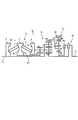
従来、トロイダル式無段変速装置を用い、一軸状に各部材を配置した無段変速機が提案されている(特許文献1)。該無段変速機1は、図6(a)に示すように、入力ディスク2、出力ディスク3及びこれら両ディスクの間に配置されて両ディスクとの接触半径位置を変更し得るローラ4からなるトロイダル式無段変速装置5と、3個のピニオンP1,P2,P3を軸方向に配置したキャリヤC1を有するプラネタリギヤ機構6と、2個のピニオンP4,P5を軸方向に配置したキャリヤC2を有する反転ギヤ機構7と、反転ギヤ機構の出力側サンギヤS4を停止し得るローブレーキL及びプラネタリギヤの第2のサンギヤ(ハイモード用出力ギヤ)S2と出力軸13との間に介在するハイクラッチHからなるロー・ハイ切換え機構10と、を備え、これら各部材が、入力軸12と出力軸13との間に一軸状に配置して構成されている。 2. Description of the Related Art Conventionally, a continuously variable transmission using a toroidal-type continuously variable transmission and uniaxially arranged members has been proposed (Patent Document 1). As shown in FIG. 6 (a), the continuously
これにより、本無段変速機1は、ローブレーキLを係合すると共にハイクラッチHを解放したローモードにあっては、入力軸12の回転を直接入力するキャリヤC1と無段変速装置5を介して反転・変速された入力側サンギヤS1の回転とをプラネタリギヤ機構6にて合成して、ローモード用出力ギヤ(第3のサンギヤ)S3に出力し、更に該出力ギヤS3の回転を反転して出力軸13に出力している。 Thus, in the continuously
なお、ロー・ハイ切換え機構10は、図6(b)に示すように、キャリヤC2と出力軸13との間に介在するロークラッチLと、先のものと同様な、プラネタリギヤの第2のサンギヤS2と出力軸13との間に介在するハイ用クラッチHとにより構成してもよい。 As shown in FIG. 6B, the low /
本無段変速機にあっては、プラネタリギヤ機構6が3個のピニオンP1,P2,P3を軸方向に直列状に並べた上、反転ギヤ機構7も、2個のピニオンP4,P5を軸方向に直列状に並べて配置するため、軸方向に長い構成になってしまう。 In this continuously variable transmission, the planetary gear mechanism 6 has three pinions P1, P2, and P3 arranged in series in the axial direction, and the
そこで、本出願の発明者らは、反転ギヤ機構にデュアルプラネタリギヤを用い、軸方向の短縮化を図った無段変速機を考案した。本無段変速機11は、図7に示すように、トロイダル式無段変速装置5、プラネタリギヤ機構6は先に説明したものと同じであるが、反転ギヤ機構71がデュアルプラネタリギヤからなる。即ち、キャリヤC0が互いに噛合するピニオンP4,P5を回転自在に支持し、一方のピニオンP4がサンギヤS0に、他方のピニオンP5がリングギヤR0に噛合し、そしてサンギヤS0が上記プラネタリギヤ機構6の第3のサンギヤ(ローモード用出力ギヤ)S3と連結し、リングギヤR0がケース15に固定され、キャリヤC0がロークラッチLを介して出力軸13に連結している。In view of this, the inventors of the present application have devised a continuously variable transmission that uses a dual planetary gear for the reversing gear mechanism and is shortened in the axial direction. This continuously
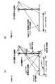
そして、本無段変速機11は、図8の速度線図に示すように作動する。即ち、ロークラッチLを係合してハイクラッチHを解放したローモードにあっては、図8(a)に示すように、入力軸12の回転は(例えばエンジン出力回転)、中心軸12aを介してプラネタリギヤ機構6のキャリヤC1に伝達されると共に、トロイダル式無段変速装置(バリエータ)5を介して反転されて第1のサンギヤ(入力ギヤ)S1に伝達される。上記キャリヤC1への定速回転と入力ギヤS1の反転変速回転がプラネタリギヤ機構6でトルク循環しつつ合成されて第3のサンギヤ(ローモード用側出力ギヤ)S3から出力する。Then, the continuously
ここで、入力側ギヤ比(S1/P1)と出力側ギヤ比(S3/P3)との関係で、無段変速装置(バリエータ)5が最もオーバードライブ(OD;増速側)にある場合、出力ギヤS3は、逆転方向(入力軸12の回転方向を正転方向とする)に回転し、上記バリエータ5がODからアンダードライブ(UD;減速側)に変速することにより、0回転(GN;ギヤニュートラル)ポイントを経て正転方向になり、そしてバリエータ5が最もUD側になると、最大正転回転となる。 Here, in the relationship between the input side gear ratio (S1 / P1) and the output side gear ratio (S3 / P3), when the continuously variable transmission (variator) 5 is at the most overdrive (OD; speed increasing side), The output gear S3 rotates in the reverse rotation direction (the rotation direction of the
該出力ギヤS3の回転は、それと一体の反転ギヤ機構71の入力サンギヤS0に伝達され、リングギヤR0が停止されているため、反転されてキャリヤC0から出力する。該キャリヤC0の回転は、接続状態にあるロークラッチLを介して出力軸13に伝達される。従って、出力ギヤS3の逆転回転が、キャリヤC0及び出力軸13では正転回転となるが、本無段変速装置11を自動車のトランスミッションに用いる場合、該無段変速機11の伝動後流側におけるディファレンシャル装置において再度反転機構(図示せず)が介在されており、上記出力軸13の正回転は、車輌の後進回転出力となる。即ち、バリエータ5のODからUDへの変速により、出力軸(キャリヤC0)13は、後進回転からGNポイント(0回転)を経て前進回転に変速される。Rotation of the output gear S3 is therewith is transmitted to the input sun gear S0 of the
ロークラッチLを解放すると共に、ハイクラッチHを係合すると、ハイモードに切換えられる。この状態では、プラネタリギヤ機構6の第2のサンギヤ(ハイモード用出力ギヤ)S2の回転がハイクラッチHを介して出力軸13からそのまま出力する。図8(b)に示すように、入力軸12の回転は、プラネタリギヤ機構6のキャリヤC1に直接伝達されると共に、トロイダル式無段変速装置(バリエータ)5を介して反転して第1のサンギヤ(入力ギヤ)S1に伝達される。 When the low clutch L is released and the high clutch H is engaged, the mode is switched to the high mode. In this state, the rotation of the second sun gear (high mode output gear) S2 of the planetary gear mechanism 6 is directly output from the
上記キャリヤC1の正転定速回転と、第1のサンギヤS1の反転変速回転がプラネタリギヤ機構6で合成されて、第2のサンギヤS2から出力するが、ここで、入力側ギヤ比(S1/P1)と出力側ギヤ比(S2/P2)とは近い値又は同じ値にあり、バリエータ5の変速比(ギヤ比)が、上記ローモードにおけるバリエータの最UD時における前進出力速度に略々対応する値だけ逆転方向にずれて出力速度となる。即ち、バリエータ5が最UD状態にある場合、第2のサンギヤ(出力ギヤ)S2は、ハイモードにおける最小前進出力速度となり、バリエータ5がUD側からOD側に変速するに従って、前進出力速度が増速する。なお、自動車の出力としては、再反転機構により逆転側が前進方向となる。 The forward rotation of the carrier C1 and the reverse rotation of the first sun gear S1 are combined by the planetary gear mechanism 6 and output from the second sun gear S2. Here, the input side gear ratio (S1 / P1) ) And the output side gear ratio (S2 / P2) are close to or equal to each other, and the transmission ratio (gear ratio) of the variator 5 substantially corresponds to the forward output speed at the maximum UD of the variator in the low mode. The output speed is shifted by the value in the reverse direction. That is, when the variator 5 is in the maximum UD state, the second sun gear (output gear) S2 becomes the minimum forward output speed in the high mode, and the forward output speed increases as the variator 5 shifts from the UD side to the OD side. Speed up. As for the output of the automobile, the reverse side becomes the forward direction by the re-inversion mechanism.
従って、本無段変速機11は、ローモードにあって、バリエータ5が最OD状態にある場合、後進最大速となり、バリエータ5をUD方向に変速することにより、ギヤニュートラル(GN)ポイントを経て、前進状態となって前進方向で増速して、バリエータ5の最UD位置で、ローモードでの前進最大出力速度になる。そして、この状態でハイモードに切換えられると、バリエータ5の最UD位置において、ハイモードにおける前進最小出力速度となり、該最小出力速度と上記ローモードでの最大出力速度は略々同じとなる。ハイモードにおいて、バリエータ5をOD方向に変速するに応じて、前進出力速度も増速して、バリエータ5の最OD位置において、前進最大出力速度となる。Accordingly, when the continuously variable transmission11 is in the low mode and the variator 5 is in the maximum OD state, the maximum reverse speed is achieved, and the gear neutral (GN) point is set by shifting the variator 5 in the UD direction. After that, the vehicle enters the forward state and increases in the forward direction, and reaches the maximum forward output speed in the low mode at the maximum UD position of the variator 5. When the high mode is switched in this state, the forward minimum output speed in the high mode is obtained at the maximum UD position of the variator 5, and the minimum output speed and the maximum output speed in the low mode are substantially the same. In the high mode, as the variator 5 is shifted in the OD direction, the forward output speed is also increased to the maximum forward output speed at the maximum OD position of the variator 5.
これにより、本無段変速機11は、バリエータ5をODからUD方向に変速することにより、後進からギヤニュートラルを経て前進方向に変速され、そしてバリエータを最UD位置からOD方向に変速することにより、前進方向に連続して更に増速して最大出力速度になる。Thus, the present continuously
上記図7に示す無段変速機11は、反転ギヤ機構にデュアルプラネタリギヤを用いて軸方向の短縮化を図っているが、トルク合成用のプラネタリギヤ機構6は、上記特許文献1(図6参照)に示す無段変速機1と同様に、3個のピニオンを軸方向にしたもの(3ステップピニオン)を用いている。
該プラネタリギヤ機構6は、図9に示すように、3個のピニオンP1,P2,P3を軸方向に直列的に支持するキャリヤC1と、第1のピニオンP1に噛合する第1のサンギヤ(入力ギヤ)S1と、第2のピニオンP2に噛合する第2のサンギヤ(ハイモード用出力ギヤ)S2と、第3のピニオンP3に噛合する第3のサンギヤ(ローモード用出力ギヤ)S3と、を有する。キャリヤC1は、トロイダル式無段変速装置(バリエータ5)の一方のディスク2と一体に形成されたキャリヤ本体21aと、該本体と一体のキャリヤカバー21bとを有しており、該キャリヤ本体21aは、ミッションケース22にベアリング24を介して回転自在に支持されている。また、該キャリヤ本体21a及びカバー21bにはピニオンシャフト23が設けられており、該シャフト23には一体に形成された上記第1,第2,第3のピニオンP1,P2,P3がニードルベアリング29又はブッシュを介して回転自在に支持されている。なお、ブシュもベアリング概念に含まれる。 As shown in FIG. 9, the planetary gear mechanism 6 includes a carrier C1 that supports three pinions P1, P2, and P3 in series in the axial direction, and a first sun gear (input gear) that meshes with the first pinion P1. ) S1, a second sun gear (high mode output gear) S2 meshing with the second pinion P2, and a third sun gear (low mode output gear) S3 meshing with the third pinion P3 . The carrier C1 includes a carrier
第1のサンギヤS1は、中空軸25の先端部に形成されており、該中空軸25の基部には上記バリエータ5の中央出力ディスク3(図6,図7参照)が連結している。該中空軸25の中空部には、入力軸(中心軸)12がニードルベアリング等により回転自在に支持されており、該入力軸12は、その基部(車輌前方)においてダンパを介してエンジン出力軸に連結されており、またその先端部(車輌後方)において前記キャリヤ本体21aがスプライン結合している。第2のサンギヤS2は、中間軸26に形成されており、該中間軸は、前記ロー・ハイ切換え機構のハイクラッチHに連結している(図6,図7参照)。第3のサンギヤS3は、上記中間軸26に回転自在に被嵌しているスリーブ27に形成されており、該スリーブ27は、前記反転ギヤ機構7のサンギヤS0(図6,図7参照)に連結している。 The first sun gear S <b> 1 is formed at the tip of the
上記ピニオンシャフト23は、軸方向に直列的に一体に形成された3個のピニオンP1,P2,P3を支持している関係上、軸方向に長い構成になっており、かつ上述したように、トルク循環を伴う無段変速機(IVT;infinitely variable transmission)を構成するため、即ちローモードにおける前進最高出力速度とハイモードにおける前進最低出力速度とをバリエータ5の最UDにおいて略々一致させて変速を連続させるため、第3のピニオンギヤP3のギヤ径が小さくなり、そのためピニオンシャフト23の径も小さくなってしまう。 The
この結果、ベアリング29の径も小さくなり、ベアリングの寿命容量が小さくなり、かつピニオンシャフトが小径化となることによりシャフトの剛性不足によりシャフト撓みに基づくベアリングへの負荷の増大が相俟って、キャリヤC1の精度及び寿命が充分にとれない虞がある。 As a result, the diameter of the
更に、3個の一体に形成したピニオンP1,P2,P3は重量も重くなり、キャリヤC1に大きな遠心荷重が作用し、プラネタリギヤ機構6は、遠心荷重等の負荷に対しても不利な構造となっている。 Further, the three integrally formed pinions P1, P2, and P3 are heavier, a large centrifugal load acts on the carrier C1, and the planetary gear mechanism 6 has a disadvantageous structure against a load such as a centrifugal load. ing.
また、3個のピニオンP1,P2,P3を軸方向に直列的に並べて配置するため、プラネタリギヤ機構6が軸方向に長い構造となり、反転ギヤ機構の短縮化が図れたとしても、無段変速機として依然として軸方向に長い構造となっている。 In addition, since the three pinions P1, P2, and P3 are arranged in series in the axial direction, the planetary gear mechanism 6 has a structure that is long in the axial direction, and even if the reversing gear mechanism can be shortened, the continuously variable transmission It still has a long structure in the axial direction.
そこで、本発明は、プラネタリギヤ機構を軸方向に短い構造として、もって上述した課題を解決した無段変速機を提供することを目的とするものである。 Accordingly, an object of the present invention is to provide a continuously variable transmission that solves the above-described problems by using a planetary gear mechanism having a short structure in the axial direction.
なお、図7及び図9に示す無段変速機の構成は、本発明の出願時において未公開のものである。 The configuration of the continuously variable transmission shown in FIGS. 7 and 9 has not been disclosed at the time of filing of the present invention.
請求項1に係る本発明は、トロイダル式無段変速装置(5)と、プラネタリギヤ機構(61)と、反転ギヤ機構(71)と、ロー・ハイ切換え機構(10)と、を入力軸及び出力軸に対して1軸上に備えてなる、無段変速機(12)において、
前記トロイダル式無段変速装置(5)は、2個の入力ディスク(2,2)と、これらディスクの間に位置する出力ディスク(3)と、前記入力ディスクと出力ディスクとに挟持されるローラ(4,4)と、を有し、
前記プラネタリギヤ機構(61)は、第1のピニオンシャフト(36)及び第2のピニオンシャフト(37)を有するキャリヤ(C)と、第1のサンギヤ(S1)と、第2のサンギヤ(S2)と、リングギヤ(R3)と、を有し、
前記第1のピニオンシャフト(36)に、一体に回転する第1のピニオン(P1)と第2のピニオン(P2)とを支持し、前記第2のピニオンシャフト(37)に第3のピニオン(P3)を支持し、かつ前記第2のピニオン(P2)と第3のピニオン(P3)とを互いに噛合し、
前記第1のピニオン(P1)と前記第1のサンギヤ(S1)とを噛合し、前記第2のピニオン(P2)と前記第2のサンギヤ(S2)とを噛合し、前記第3のピニオン(P3)と前記リングギヤ(R3)とを噛合し、
前記2個の入力ディスクの一方(2)を前記入力軸(12)に連結すると共に、前記キャリヤ(C)を前記入力ディスクの他方(2)及び前記入力軸(12)に連結し、
前記出力ディスク(3)と前記第1のサンギヤ(S1)とを連結し、かつ該第1のサンギヤ(S1)及び前記第1のピニオン(P1)を、前記第2のサンギヤ(S2)及び第2のピニオン(P2)に対して軸方向前記トロイダル式無段変速装置(5)側に配置し、
前記他方の入力ディスク(2)の背面と前記キャリヤ(C)との間に、固定部材(22)に装着されたベアリング(24)を配置して、該ベアリング(24)にて前記他方の入力ディスク(2)及びキャリヤ(C)の連結部分(m,n)を回転自在に支持し、
前記キャリヤ(C)に、前記入力軸(12)からの定速回転を入力すると共に、前記第1のサンギヤ(S1)に、前記入力軸(12)の回転を前記トロイダル式無段変速装置(5)にて反転・変速した出力回転を入力し、
前記ロー・ハイ切換え機構(10)によるローモードにあっては、前記リングギヤ(R3)の回転を前記反転ギヤ機構(71)により反転して前記出力軸(13)に出力し、
前記ロー・ハイ切換え機構(10)によるハイモードにあっては、前記第2のサンギヤ(S2)の回転を前記出力軸(13)に出力する、
ことを特徴とする無段変速機にある。Input present invention according to
The toroidal-type continuously variable transmission (5) includes two input disks (2, 2), an output disk (3) positioned between the disks, and a roller sandwiched between the input disk and the output disk. (4, 4)
The planetary gear mechanism (61 ) includes a carrier (C) having a first pinion shaft (36) and a second pinion shaft (37), a first sun gear (S1), and a second sun gear (S2). And a ring gear (R3),
The first pinion shaft (36) supports a first pinion (P1) and a second pinion (P2) that rotate together, and a third pinion (37) is supported on the second pinion shaft (37). P3) and meshing the second pinion (P2) and the third pinion (P3) with each other,
The first pinion (P1) meshes with the first sun gear (S1), the second pinion (P2) meshes with the second sun gear (S2), and the third pinion ( P3) and the ring gear (R3) are meshed,
One of the two input disks (2) is connected to the input shaft (12), and the carrier (C) is connected to the other input disk (2) and the input shaft (12),
The output disk (3) and the first sun gear (S1) are connected, and the first sun gear (S1) and the first pinion (P1) are connected to the second sun gear (S2) and the second sun gear (S1). 2 on the toroidal continuously variable transmission (5) side in the axial direction with respect to the pinion (P2),
A bearing (24) mounted on a fixing member (22) is disposed between the back surface of the other input disk (2) and the carrier (C), and the other input is made by the bearing (24). A connecting portion (m, n) of the disk (2) and the carrier (C) is rotatably supported;
Wherein the carrier (C), inputs the constant speed rotation fromthe input shaft (12), wherein the first sun gear (S1), the toroidal type continuously variable transmission of rotation of said input shaft (12) ( Input the output rotation that has been reversed and changed in step 5),
In the said low mode by low-high switching mechanism (10) outputs the rotation of the ring gear (R3) to the reversing gear mechanism(71)said output shaft is inverted by (13),
In the high mode by the low / high switching mechanism (10), the rotation of the second sun gear (S2) is output to the output shaft (13).
It is in the continuously variable transmission characterized by this.
請求項2に係る本発明は、前記反転ギヤ機構(71)は、互いに噛合する第1及び第2のピニオン(P4,P5)を支持するキャリヤ(C0)と、前記第1のピニオンに噛合するサンギヤ(S0)と、前記第2のピニオンに噛合するリングギヤ(R0)と、を有するデュアルプラネタリギヤからなり、
前記プラネタリギヤ機構(61)の前記リングギヤ(R3)を、前記反転ギヤ機構(71)の前記キャリヤ(C0)及びサンギヤ(S0)のいずれか一方に連結し、前記ローモードにあっては、前記リングギヤ(R0)を停止した状態で前記キャリヤ(C0)及びサンギヤ(S0)のいずれか他方の回転を前記出力軸(13)に伝達してなる、
請求項1記載の無段変速機にある。According to asecond aspect of the present invention, the reversing gear mechanism (71 ) meshes with the first pinion and the carrier (C0) supporting the first and second pinions (P4, P5) meshing with each other. A dual planetary gear having a sun gear (S0) that engages and a ring gear (R0) that meshes with the second pinion,
The ring gear (R3) of the planetary gear mechanism (61 ) is connected to one of the carrier (C0) and the sun gear (S0) of the reversing gear mechanism (71 ), and in the low mode, The rotation of either the carrier (C0) or the sun gear (S0) is transmitted to the output shaft (13) with the ring gear (R0) stopped.
A continuously variable transmission according to
請求項3に係る本発明は、前記入力軸(12)に、前記一方の入力ディスク(2)と前記キャリヤ(C)とが互いに離れる方向にスラスト力を作用するように支持して、前記トロイダル式無段変速装置(5)及び前記キャリヤ(C)を、前記ベアリング(24)を間に介在してスラスト力に対してクローズに支持してなる、
請求項1又は2記載の無段変速機にある。
請求項4に係る本発明は、回転方向及びスラスト方向に一体に構成した前記キャリヤ(C)又は入力軸(12)に対して、前記第1及び第2のサンギヤ(S1)(S2)をスラストベアリング(42)(43)を介してスラスト方向に支持してなる、
請求項3記載の無段変速機にある。According to athird aspect of the present invention, there is provided theinput shaft (12), wherein the one input disk (2) and the carrier (C) are supported so as to exert a thrust force in a direction away from each other. The continuously variable transmission (5) and the carrier (C) are supported close to the thrust force with the bearing (24) interposed therebetween.
The continuously variable transmission according to
The present invention according to
A continuously variable transmission according to
なお、上記カッコ内の符号は、図面と対照するためのものであるが、これにより請求項の記載に何等影響を及ぼすものではない。 In addition, although the code | symbol in the said parenthesis is for contrast with drawing, it does not have any influence on description of a claim by this.
請求項1に係る本発明によると、プラネタリギヤ機構は、2列・4要素タイプのプラネタリギヤからなり、ピニオンシャフトは、軸方向の2列のピニオンを支持する短い構成で足り、その結果、2列のピニオンを回転自在に支持するベアリングも径の大きいものを用いることが可能となって、ベアリング寿命容量を向上し、かつピニオンシャフトの撓みを減少して、それに伴うベアリングの負荷変動を減少し、更にピニオン重量も軽くなって、遠心荷重による負荷を減少し、これらが相俟ってピニオンの支持精度を向上すると共にその高い精度を長期に亘って維持することができる。 According to the first aspect of the present invention, the planetary gear mechanism comprises a two-row / four-element type planetary gear, and the pinion shaft only needs to have a short configuration to support two rows of pinions in the axial direction. The bearing that supports the pinion in a freely rotatable manner can be used with a large diameter, improving the bearing life capacity and reducing the deflection of the pinion shaft, thereby reducing the load fluctuation of the bearing, and The weight of the pinion is reduced and the load due to the centrifugal load is reduced. Together, these improve the support accuracy of the pinion and maintain the high accuracy over a long period of time.
更に、プラネタリギヤ機構は、2列のプラネタリギヤの内の1個のピニオンとリングギヤのない小径構造のものをトロイダル式無段変速装置側に配置したので、トロイダル式無段変速装置の入力ディスク背面とプラネタリギヤ機構のキャリヤとを、その溝に、固定部材に装着されたベアリングを配置して回転支持して、軸位置精度及び組立性を向上できる。Further, since theplanetary gear mechanism has one pinion of two rows of planetary gears and a small-diameter structure without a ring gear arranged on the toroidal continuously variable transmission side, the back surface of the input disk of the toroidal continuously variable transmission and the planetary gears. The bearing of the mechanism is rotatably supported by disposing a bearing attached to the fixed member in the groove, thereby improving the axial position accuracy and the assemblability.
請求項1に係る本発明によると、プラネタリギヤ機構は、いわゆるラビニヨタイプのプラネタリギヤからなり、第1のプラネタリシャフトは、第1のピニオン及び第2のピニオンを支持する短い構成で足り、かつリングギヤがローモード用出力ギヤとなるため、トロイダル式無段変速装置のアンダードライブ及びオーバードライブの両方向の変速を利用する無段変速機(トルク循環を伴うIVT)の機能を達成するギヤ比を得るための第2のピニオンシャフトに対する影響は少なく、第2のピニオンシャフトに比較的大径のものを用いることが可能となる。According to thefirst aspect of the present invention, the planetary gear mechanism is a so-called Ravigneaux type planetary gear, the first planetary shaft is sufficient to support the first pinion and the second pinion, and the ring gear is in the low mode. To obtain a gear ratio that achieves the function of a continuously variable transmission (IVT with torque circulation) that uses a shift in both directions of underdrive and overdrive of a toroidal continuously variable transmission. This has little influence on the pinion shaft, and a second pinion shaft having a relatively large diameter can be used.
その結果、第1及び第2のピニオンを回転自在に支持するベアリングも径の大きいものを用いることが可能となって、ベアリング寿命容量を向上し、かつ第2のピニオンシャフトが短くかつ太い構成の剛性の高いものからなることにより、該シャフトの撓みを減少して、それに伴うベアリングの負荷変動を減少し、更にピニオン重量も軽くなって、遠心荷重による負荷を減少し、これらが相俟ってピニオンの支持精度を向上すると共にその高い精度を長期に亘って維持することができる。 As a result, a bearing that rotatably supports the first and second pinions can be used with a large diameter, the bearing life capacity can be improved, and the second pinion shaft has a short and thick configuration. By being made of a highly rigid material, the deflection of the shaft is reduced, the bearing load fluctuation associated therewith is reduced, the pinion weight is also lightened, the load due to centrifugal load is reduced, and these together The pinion support accuracy can be improved and the high accuracy can be maintained over a long period of time.
更に、ローモードでの出力ギヤとなるリングギヤと、ハイモードでの出力ギヤとなる第2のサンギヤとが、軸方向にオーバーラップして配置されるので、プラネタリギヤ機構を軸方向に短縮化して、無段変速機をコンパクトに構成することができる。 Furthermore, since the ring gear that is the output gear in the low mode and the second sun gear that is the output gear in the high mode are arranged overlapping in the axial direction, the planetary gear mechanism is shortened in the axial direction, The continuously variable transmission can be configured compactly.
また、入力軸及びトロイダル変速装置の入力ディスクをキャリヤに連結し、トロイダル変速装置の出力ディスクを第1のサンギヤに連結して、トロイダル変速装置の中心部を2重軸により構成して、コンパクトで合理的な連結関係となる。 In addition, the input shaft and the input disk of the toroidal transmission are connected to the carrier, the output disk of the toroidal transmission is connected to the first sun gear, and the central part of the toroidal transmission is constituted by a double shaft, which is compact. A rational consolidated relationship.
請求項2に係る本発明によると、反転ギヤ機構がデュアルプラネタリギヤからなるので、該反転ギヤ機構を軸方向に短縮化して、更なる無段変速機のコンパクト化、特に軸方向の短縮化を図ることができる。According to thesecond aspect of the present invention, since the reversing gear mechanism is composed of a dual planetary gear, the reversing gear mechanism is shortened in the axial direction to further reduce the size of the continuously variable transmission, particularly in the axial direction. be able to.
請求項3に係る本発明によると、大きな軸方向(スラスト)力が作用するトロイダル式無段変速装置を、その入力ディスクと実質的に一体の入力軸及びプラネタリギヤ機構のキャリヤを含めてクローズドに支持し、更に請求項4に係る本発明によると、このものに、第1及び第2のサンギヤに作用するスラスト力も含めてクローズドに支持するので、トロイダル式無段変速装置及びプラネタリギヤ機構を1つの系としてスラスト力をクローズに支持して、ケース及び該ケースに対するスラストベアリング等に大きなスラスト負荷を与えることがなく、高い支持精度を長期に亘って維持して、無段変速機の長寿命化を図ることができる。According to thethird aspect of the present invention, the toroidal continuously variable transmission acting with a large axial (thrust) force is supported in a closed manner including the input shaft substantially integrated with the input disk and the carrier of the planetary gear mechanism. Further, according to the present invention of
以下、図1〜5に沿って、本発明の最良の形態について説明する。 The best mode of the present invention will be described below with reference to FIGS.
無段変速機(IVT)12は、図1に示すように、無段変速装置(バリエータ)5、プラネタリギヤ機構61、反転ギヤ機構71、及びロー・ハイ切換え機構10を入力軸12及び出力軸13に1軸上に配置して構成される。無段変速装置5は、フルトロイダル式無段変速装置からなり、入力軸12に連結された2個の入力ディスク2,2と、中空軸25に連結された1個の出力ディスク3と、両ディスクの間に挟持されるパワーローラ4,4と、を有する。入力ディスク2及び出力ディスク3は、それぞれ対向するように円形の一部を形成する円弧状の凹溝2a,3aを有しており、2列のパワーローラを挟んでダブルキャビティを構成して、入力ディスク同士のスラスト力を打ち消す構成からなる。パワーローラ4,4は、軸に直角方向にシフトさせることにより傾斜して、入力ディスク2と出力ディスク3との接触半径を変更することにより、無段に連続して変速する。本バリエータ5にあっては、−0.4〜−2.5の速度比(出力速度/入力速度)を有する。なお、入力ディスク2に対して出力ディスク3が反転するので、速度比は−(マイナス)になる。CVT (IVT)1 2, as shown in FIG. 1, a continuously variable transmission (variator) 5, the planetary gear mechanism6 1, reversing gear mechanism7 1 and the low-
プラネタリギヤ機構61は、軸方向に2列のプラネタリギヤを有し、かつ4個の外部連結要素を有する2列・4要素タイプのプラネタリギヤからなり、好ましくは1個のシンプルプラネタリギヤ及び1個のデュアルプラネタリギヤを有するラビニヨタイプのプラネタリギヤからなる。該プラネタリギヤ機構61は、長いピニオンシャフトと短いピニオンシャフトとを支持するキャリヤ(第1の要素)Cを有し、長いピニオンシャフトに軸方向に直列的に2個のピニオンP1,P2を回転自在に支持し、短いピニオンシャフトに1個のピニオンP3を回転自在に支持している。該キャリヤCは、入力軸12に連結されていると共に一方の入力ディスク2に結合されており、一定速回転が伝達されている。Planetary gear mechanism 61 has a planetary gear of the two rows in the axial direction, and a two-row-4 element type planetary gear having four external coupling elements, preferably one of the simple planetary gear and one of the dual planetary gear Ravigneaux type planetary gear having The planetary gear mechanism 61, long pinion shaft and has a short pinion shaft and a carrier for supporting the (first element) C, rotatable axially long pinion shafts serially two pinions P1, P2 One pinion P3 is rotatably supported on a short pinion shaft. The carrier C isRi Contact is coupled to one
第1のピニオンP1には、バリエータ5の出力ディスク3に連結されている第1のサンギヤ(第2の要素)S1が噛合しており、該第1のサンギヤS1は、バリエータ5による変速回転を入力する入力ギヤとなる。第2のピニオンP2と第3のピニオンP3とは、互に噛合して同一平面上(互いに軸方向にオーバーラップして)に配置されており、第2のピニオンP2が第2のサンギヤS2に噛合し、第3のピニオンP3がリングギヤR3に噛合している。第2のサンギヤ(第4の要素)S2は、ロー・ハイ切換え機構10のハイクラッチHを介して出力軸13に連結して、ハイモード用出力ギヤを構成している。リングギヤ(第3の要素)R3は、反転ギヤ機構71のキャリヤC0に連結して、ローモード用出力ギヤを構成している。The first sun gear (second element) S1 connected to the
反転ギヤ機構71は、互いに噛合する2個のピニオン(第1のピニオンP4,第2のピニオンP5)を有するデュアルプラネタリギヤからなり、そのキャリヤC0が上述したようにリングギヤR3に連結しており、リングギヤR0がケース22に固定されており、そしてサンギヤS0がロークラッチLを介して出力軸13に連結している。Reversing
本無段変速機(IVT)12は、図2の変速線図に示すように作動する。なお、図2の速度線図は、第1及び第2のピニオンP1,P2を共通のロングピニオンとし、ギヤ比S1/P1とS2/P2とを同じにして、出力速度とバリエータ出力ラインとが重なるものを示しているが、上記ギヤ比(S1/P1)(S2/P2)を変えて、図8に示す速度線図に示すように、出力速度とバリエータ出力ラインとが重ならないようにしてもよいことは勿論である。なお、ギヤ比S1/P1とS2/P2を変えることにより、バリエータに比べて伝達効率の良いギヤ比にトルクを分配することができ、トランスミッション(無段変速機)全体の効率を上げることができる。また、上記ギヤ比を同じとした場合、ハイモードにおける出力ギヤS2を増速して、トランスミッション(無段変速機)全体のギヤレシオをハイギヤード化して、高速運転域での燃費を向上することができる。This continuously variable transmission (IVT) 12 operates as shown in the shift diagram of FIG. In the speed diagram of FIG. 2, the first and second pinions P1 and P2 are common long pinions, the gear ratios S1 / P1 and S2 / P2 are the same, and the output speed and the variator output line are Although the overlap is shown, change the gear ratio (S1 / P1) (S2 / P2) so that the output speed and the variator output line do not overlap as shown in the speed diagram shown in FIG. Of course, it is also good. By changing the gear ratios S1 / P1 and S2 / P2, it is possible to distribute torque to a gear ratio with better transmission efficiency compared to the variator, and to increase the overall efficiency of the transmission (continuously variable transmission). . Further, if the gear ratio is the same, the output gear S2 in the high mode can be increased to increase the gear ratio of the entire transmission (continuously variable transmission), thereby improving the fuel efficiency in the high-speed driving range. .
ロークラッチLを係合してハイクラッチHを解放したローモードにあっては、図2(a)に示すように、エンジン出力軸に連結している入力軸12の回転は、プラネタリギヤ機構61のキャリヤCに直接伝達されると共に、バリエータ5を介して反転した変速回転が第1のサンギヤ(入力ギヤ)S1に伝達される。上記キャリヤCの定速回転及び第1のサンギヤS1の変速回転(バリエータギヤ比)がプラネタリギヤ機構61にてトルク循環しつつ合成され、ローモード用出力ギヤであるリングギヤR3に出力する。ここで、バリエータ5がOD側からUD側に変速することにより、出力リングギヤR3は、反転回転からギヤニュートラル位置(GNポイント)、即ち出力速度が0となってトルクが無限に発散する位置となり、更にOD側に変速することにより正転側(入力軸回転と同じ方向)に増速する。It is a low clutch L to engage the low mode releasing the high clutch H, as shown in FIG. 2 (a), the rotation of the
そして、該出力リングギヤR3の回転は、反転ギヤ機構71のキャリヤC0に直接伝達され、リングギヤR0の停止に基づき反転されてサンギヤS0から出力する。これにより、上記出力リングギヤR3及びキャリヤC0の回転は反転され、出力リングギヤR3の逆回転は、サンギヤS0に後進出力速度として出力し、出力リングギヤR3の正回転は、サンギヤS0に前進出力速度として出力する。The rotation of the output ring gear R3 is transferred directly to the carrier C0 of the
ロークラッチLを解放すると共に、ハイクラッチHを係合すると、ハイモードに切換えられる。この状態では、入力軸12の回転が、プラネタリギヤ機構61のキャリヤCに直接伝達されると共に、バリエータ5により反転した変速回転が第1のサンギヤS1に伝達されて、該プラネタリギヤ機構61にて合成されて、ハイモード用出力ギヤである第2のサンギヤS2から出力する。なおこの際、ロークラッチLが解放していることに基づき、反転ギヤ機構71のサンギヤS0及びキャリヤC0が空転し、従ってプラネタリギヤ機構61のリングギヤR3も空転する。また、ギヤ比S1/P1とS2/P2とが同じであるため、バリエータ5からの変速出力回転(バリエータギヤ比)と同じ回転が上記第2のサンギヤS2から出力し、該バリエータギヤ比がハイクラッチHの接続により出力軸13からハイモード前進出力速度として出力する。When the low clutch L is released and the high clutch H is engaged, the mode is switched to the high mode. In this state, the rotation of the
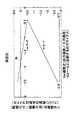
以上のことを図3のグラフで説明すると、ローモードにあっては、バリエータ5の速度比(出力速度/入力速度)がOD端(約−2.5)にある場合、無段変速機(IVT)12は、正転方向(プラス方向)に所定速度比(約0.25)で回転し、バリエータ5がUD側に連続して変速することにより、上記IVT12の速度比は連続して減速し、バリエータ5の−1.8付近の速度比においてIVT12の速度比は、0、即ちギヤニュートラル(GNポイント)になる。更にバリエータ5をUD方向に連続して変速することにより、IVT12の速度比は逆転方向(マイナス方向)に連続して増速し、バリエータ5がUD端(約−0.4)に至ると、IVT12の速度比が約−0.5になる。The above will be described with reference to the graph of FIG. 3. In the low mode, when the speed ratio (output speed / input speed) of the variator 5 is at the OD end (about −2.5), the continuously variable transmission ( IVT)1 2 is rotated at a predetermined speed ratio (approximately 0.25) in the forward direction (positive direction), by the variator 5 is shifting continuously the UD side, the speed ratio of the IVT12 is continuously decelerated Te, IVT12 speed ratio in the speed ratio in the vicinity of -1.8 of the
そしてこの状態で、ハイモードに切換えられる。ハイモードにあっては、バリエータ5の速度比が上記UD端にある場合、IVT12の速度比が上記ローモードの場合と同じ値(約−0.5)になり、今度は、バリエータの速度比を、上記UD端から連続してOD方向に変速すると、IVT12の速度比は、上記ローモードから連続して逆転方向(マイナス方向)に増速する。該逆転方向の増速は、バリエータ5がOD方向に変速することにより連続し、バリエータ5の速度比がOD端(約−2.5)に至ると、IVT12の速度比は、最大変速比である約−2.75となる。In this state, the mode is switched to the high mode. In the high mode, when the speed ratio of the variator 5 is in the UD end, the same value as when the speed ratio of IVT12 is the low mode (about -0.5), in turn, the speed of the variator the ratio, when the shift in the OD direction continuously from the UD end, the speed ratio of the IVT12 is accelerated in the reverse direction (negative direction) continuously from the low mode. Speed increasing of the reverse direction is continuous by the variator 5 is shifted to the OD direction, the speed ratio of the variator 5 reaches the OD end (about -2.5), the speed ratio of the IVT12, the maximum speed ratio Which is about -2.75.
なお、上記グラフは、入力軸12の回転方向(即ちエンジンの回転方向)を正回転として、速度比をプラスに表記し、従ってバリエータ5はトロイダル式に起因して反転するため、その速度比はマイナスとなる。本無段変速機(IVT)12は、自動車に用いられ、ディファレンシャル装置において再度反転ギヤにより反転されるため、IVT12の速度比がプラスである場合、車輌の進行方向は後進となり、該速度比がマイナスの場合、車輌の進行方向は前進となる。従って、ローモードにおいてバリエータ5をOD端からUD方向に変速することにより、自動車は、後進からギヤニュートラル(GN)を経て前進となって、徐々に増速し、そしてバリエータ5のUD端においてハイモードに切換えられ、バリエータ5がUD端からOD方向に変速することにより、自動車は、連続して前進方向に増速する。In the above graph, the rotational ratio of the input shaft 12 (that is, the rotational direction of the engine) is assumed to be positive rotation, and the speed ratio is expressed as plus. Therefore, the variator 5 is inverted due to the toroidal equation, so Negative. This continuously variable transmission (IVT) 12 is used in an automobile, because it is inverted by again reversing gear in the differential device, when the speed ratio of IVT12 is positive, the traveling direction of the vehicle becomes reverse, the velocity When the ratio is negative, the vehicle travels forward. Therefore, by shifting the variator 5 in the UD direction from the OD end in the low mode, the automobile moves forward through the gear neutral (GN), gradually increases in speed, and increases at the UD end of the variator 5. When the mode is switched and the variator 5 shifts in the OD direction from the UD end, the automobile continuously increases in the forward direction.
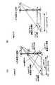
図4は、一部変更したギヤトレインを示す。本ギヤトレインにあっては、反転ギヤ機構72は、同じデュアルプラネタリギヤからなるが、そのリングギヤR0がローブレーキLに連結し、キャリヤC0が出力軸13に直接連結している。そして、プラネタリギヤ機構61のローモード出力リングギヤR3が反転ギヤ機構72のサンギヤS0に連結し、プラネタリギヤのハイモード出力ギヤS0と出力軸13との間にハイクラッチHが介在している。FIG. 4 shows a partially modified gear train. In the present gear train, the
本実施の形態にあっては、図2(a)においてローモード出力リングギヤR3と同じ箇所がサンギヤS0となる点を除いて、図2に示す速度線図と同様である。即ち、ローモードにおいて、出力リングギヤR3の回転が、反転ギヤ機構72のサンギヤS0に入力し、ローブレーキLの係合に基づくリングギヤR0の固定により反転して、キャリヤC0から出力軸13に出力する。なお、該反転ギヤ機構71,72において、入出力をサンギヤS0、キャリヤC0のどちらにしてもよいことは勿論である。The present embodiment is the same as the velocity diagram shown in FIG. 2 except that the same portion as the low mode output ring gear R3 in FIG. 2A becomes the sun gear S0. That is, in the low mode, the rotation of the output ring gear R3, and input to the sun gear S0 of the
図5は、本発明に係るプラネタリギヤの実施の形態を示す断面図である。プラネタリギヤ機構61は、シンプルプラネタリギヤ31とデュアルプラネタリギヤ32との2列からなるラビニヨタイプにて構成されている。該プラネタリギヤ機構61は、第1のピニオンP1及び第2のピニオンP2並びに第3のピニオンP3を支持するキャリヤCと、第1のピニオンP1と噛合する第1のサンギヤ(入力ギヤ)S1と、第2のピニオンP2に噛合する第2のサンギヤ(ハイモード用出力ギヤ)S2と、第3のピニオンP3に噛合するローモード用出力リングギヤR3とを有する。キャリヤCは、キャリヤ本体33と該本体と一体に結合されたキャリヤカバー35とからなる。該キャリヤ本体33の前部とバリエータ5のプラネタリギヤ機構側の入力ディスク2の背面のボス部とはドックm,nにより互いに連結されている。また、上記入力ディスク2の背面とキャリヤCとの間には、ミッションケース22に装着されたベアリング24が配置されており、該ベアリング24に、上記入力ディスク2の背面ボス部及びキャリヤ本体33の前部とが上記連結部であるドッグm,n部分において回転自在に支持されている。更に、キャリヤ本体33のスプライン連結部33aが、エンジン側の入力ディスクからバリエータ5の中心を貫通して延びている入力軸12にスプライン結合しかつナット34により締付けられている。FIG. 5 is a sectional view showing an embodiment of a planetary gear according to the present invention. Planetary gear mechanism 61 are composed of Ravigneaux type consisting of two rows of the simple
上記キャリヤ本体33とキャリヤカバー35に亘って、上記シンプル及びデュアルプラネタリギヤ31,32の両方に共通する第1のピニオンシャフト36と、デュアルピニオン32用の短い第2のピニオンシャフト37とが廻り止めされて設けられており、第1のピニオンシャフト36には、軸方向に並設して第1のピニオンP1と第2のピニオンP2とが支持され、第2のピニオンシャフト37には第3のピニオンP3が支持されている。第1のピニオンP1及び第2のピニオンP2は一体に形成されており、必ずしも同じ歯数でなくてもよいが、本実施の形態では同じ歯数からなり、これら共通ピニオンP1,P2がニードルベアリング37,37(又はブシュ)を介して上記第1のピニオンシャフト36に回転自在に支持されている。第3のピニオンP3は上記第2のピニオンシャフト37にニードルベアリング39(又はブシュ)を介して回転自在に支持されている。 A
前記第1のサンギヤS1は、中空軸25の先端部分に形成されており、該中空軸25は、入力軸12に被嵌して回転自在に支持されていると共に、その基端部分にてバリエータ5の出力ディスク3に連結されている。第2のサンギヤS2は中間軸26の基端部に形成されており、該中間軸26はその基端部分を入力軸12に被嵌して回転自在に支持されていると共に、その先端(後方)側にてロー・ハイ切換え機構10のハイクラッチHに接続している。出力リングギヤR3は、反転ギヤ機構71のキャリヤフランジ40にリング状スプライン部材41を介して抜止め固定されている。The first sun gear S1 is formed at the distal end portion of the
そして、上記キャリヤ本体33のスプライン連結部33aの前後側面と中空軸25の後端面及び中間軸26の前端面との間には、それぞれスラストベアリング42,43が介在しており、また中間軸26の第2のサンギヤS2の形成部後端面と反転ギヤ機構71のサンギヤS0の前端との間にもスラストベアリング45が介在している。これにより、第1のサンギヤS1を有する中空軸25と第2のサンギヤS2を有する中間軸26とは、それぞれ第1及び第2のピニオンP1,P2との噛合により発生するサンギヤS1,S2のスラスト力を互いに打消されると共に、入力軸12に一体に結合されたキャリヤ本体33により、プラネタリギヤ機構61内でクローズするように支持される。なお、入力軸12及びそれと一体のキャリヤCは、バリエータ5において発生する両入力ディスク2,2間の大きなスラスト力(挟圧力)を互いに相殺するようにクローズして支持しており、バリエータ5及びプラネタリギヤ機構61は、前記ベアリング24を間に介在して1個の系としてスラスト方向に対するクローズド支持構造となる。なお、スラストベアリング43をなくしてもよく、この場合、第2のサンギヤS2に作用する図面左方向のスラスト力は、中間軸25及びスナップリング48、スラストベアリング49を介してキャリヤCに作用し、該キャリヤCにて、第1のサンギヤS1のスラスト力とキャンセルされる。
上記第1のピニオンシャフト36は、2個のピニオンP1,P2を支持すれば足りる短い構造(図7に示すステップピニオンに比し)からなり、かつローモード出力用ギヤがリングギヤR3からなので、IVT12としての機能を達成するためのギヤ比の制限が少なく、第1のピニオンシャフト36を軸径の太いものを用いることができる。これにより、ベアリング37を大径のものとして、寿命容量を向上すると共に、第1のピニオンシャフト36の剛性を向上して、シャフト撓みによるベアリングの負荷変動を減少し、更にピニオン重量が軽くなり、遠心荷重による負荷を減少し、これらが相俟ってピニオンP1,P2の支持精度を長期に亘って維持することができる。The
また、第1及び第2のピニオンP1,P2に噛合する第1及び第2のサンギヤS1,S2に作用するスラスト力を、バリエータ5と一体の系としてプラネタリギヤ機構61内にてクローズして支持するので、キャリヤCのバリエータ入力ディスク2及び入力軸12との一体構造によるクローズド支持と相俟って、無段変速機12でのケース22に対するスラスト負荷を減少する。Further, the thrust force acting on the first and second sun gears S1, S2 meshing with the first and second pinions P1, P2, and closed at the planetary gear mechanism 61 as variator 5 and integral system support since, it closed support coupled with by integrated structure of the
また、プラネタリギヤ機構61は、リングギヤR3をローモード用出力ギヤとすることにより、ローモード及びハイモード用の出力ギヤR3,S2を軸方向にオーバーラップして配置し、軸方向寸法の短縮化を図ることができる。Further, the planetary gear mechanism 61, by the ring gear R3 and the low mode output gear, overlapping by placing the output gear R3, S2 for the low mode and the high mode in the axial direction, shortening of the axial dimension Can be achieved.
上記構成が相俟って、無段変速機(IVT)の精度を向上すると共に、長寿命化を図ることができ、かつコンパクト化をも図ることができる。 Together with the above configuration, the accuracy of the continuously variable transmission (IVT) can be improved, the life can be extended, and the size can be reduced.
なお、上述した実施の形態は、フルトロイダル式無段変速装置を用いているが、ハーフトロイダル式無段変速装置でもよいことは勿論である。 Although the above-described embodiment uses a full toroidal continuously variable transmission, it is needless to say that a half toroidal continuously variable transmission may be used.
12 無段変速機(IVT)
2 入力ディスク
3 出力ディスク
4 (パワー)ローラ
5 トロイダル式無段変速装置
61 プラネタリギヤ機構
71 反転ギヤ機構
10 ロー・ハイ切換え機構
12 入力軸
13 出力軸
22 (ミッション)ケース
33 キャリヤ本体
36 第1のピニオンシャフト
37 第2のピニオンシャフト
42,43 スラストベアリング
C キャリヤ
P1 第1のピニオン
P2 第2のピニオン
P3 第3のピニオン
S1 第1のサンギヤ(入力ギヤ)
S2 第2のサンギヤ(ハイモード用出力ギヤ)
R3 リングギヤ(ローモード用出力ギヤ)
L ロークラッチ、ローブレーキ
H ハイクラッチ
C0 キャリヤ
P4 (第1)のピニオン
P5 (第2)のピニオン
S0 サンギヤ
12 continuously variable transmission (IVT)
2
S2 Second sun gear (high mode output gear)
R3 ring gear (low mode output gear)
L Low clutch, Low brake H High clutch C0 Carrier P4 (First) pinion P5 (Second) pinion S0 Sun gear
Claims (4)
Translated fromJapanese前記トロイダル式無段変速装置は、2個の入力ディスクと、これらディスクの間に位置する出力ディスクと、前記入力ディスクと出力ディスクとに挟持されるローラと、を有し、
前記プラネタリギヤ機構は、第1のピニオンシャフト及び第2のピニオンシャフトを有するキャリヤと、第1のサンギヤと、第2のサンギヤと、リングギヤと、を有し、
前記第1のピニオンシャフトに、一体に回転する第1のピニオンと第2のピニオンとを支持し、前記第2のピニオンシャフトに第3のピニオンを支持し、かつ前記第2のピニオンと第3のピニオンとを互いに噛合し、
前記第1のピニオンと前記第1のサンギヤとを噛合し、前記第2のピニオンと前記第2のサンギヤとを噛合し、前記第3のピニオンと前記リングギヤとを噛合し、
前記2個の入力ディスクの一方を前記入力軸に連結すると共に、前記キャリヤを前記入力ディスクの他方及び前記入力軸に連結し、
前記出力ディスクと前記第1のサンギヤとを連結し、かつ該第1のサンギヤ及び前記第1のピニオンを、前記第2のサンギヤ及び第2のピニオンに対して軸方向前記トロイダル式無段変速装置側に配置し、
前記他方の入力ディスクの背面と前記キャリヤとの間に、固定部材に装着されたベアリングを配置して、該ベアリングにて前記他方の入力ディスク及びキャリヤの連結部分を回転自在に支持し、
前記キャリヤに、前記入力軸からの定速回転を入力すると共に、前記第1のサンギヤに、前記入力軸の回転を前記トロイダル式無段変速装置にて反転・変速した出力回転を入力し、
前記ロー・ハイ切換え機構によるローモードにあっては、前記リングギヤの回転を前記反転ギヤ機構により反転して前記出力軸に出力し、
前記ロー・ハイ切換え機構によるハイモードにあっては、前記第2のサンギヤの回転を前記出力軸に出力する、
ことを特徴とする無段変速機。In a continuously variable transmission comprising a toroidal continuously variable transmission, a planetary gear mechanism, a reversing gear mechanism, and a low / high switching mechanismon one axis withrespect to aninput shaft and an output shaft ,
The toroidal continuously variable transmission includes two input disks, an output disk positioned between the disks, and a roller sandwiched between the input disk and the output disk.
The planetary gear mechanism includes a carrier having a first pinion shaft and a second pinion shaft, a first sun gear, a second sun gear, and a ring gear,
Said first pinion shaft, supporting a first pinion and a second pinion which rotate together, the third pinion supported on the second pinion shaft and said second piniondown and the Mesh with the 3 pinions,
Meshing the first pinion and the first sun gear; meshing the second pinion and the second sun gear; meshing the third pinion and the ring gear;
Connecting one of the two input disks to the input shaft, and connecting the carrier to the other of the input disks and the input shaft;
The output disk and the first sun gear are connected, and the first sun gear and the first pinion are connected to the second sun gear and the second pinion in the axial direction. Placed on the side
A bearing mounted on a fixed member is disposed between the back surface of the other input disk and the carrier, and the connecting portion of the other input disk and the carrier is rotatably supported by the bearing.
The carrier inputs the constant speed rotation fromthe input shaft, the first sun gear, inputs the output rotation inverted-speed rotation of the input shaft in the toroidal type continuously variable transmission,
In the by low mode the low-high switching mechanism outputs rotation of the ring gear invertsthe output shaft by the reversing gear mechanism,
In the high mode by the low / high switching mechanism, the rotation of the second sun gear is output to the output shaft.
A continuously variable transmission.
前記プラネタリギヤ機構の前記リングギヤを、前記反転ギヤ機構の前記キャリヤ及びサンギヤのいずれか一方に連結し、前記ローモードにあっては、前記リングギヤを停止した状態で前記キャリヤ及びサンギヤのいずれか他方の回転を前記出力軸に伝達してなる、
請求項1記載の無段変速機。The reversing gear mechanism comprises a dual planetary gear having a carrier that supports the first and second pinions that mesh with each other, a sun gear that meshes with the first pinion, and a ring gear that meshes with the second pinion. ,
The ring gear of the planetary gear mechanism is connected to one of the carrier and the sun gear of the reversing gear mechanism, and in the low mode, the rotation of the other of the carrier and the sun gear is performed with the ring gear stopped. Is transmitted to the output shaft,
The continuously variable transmission according to claim1 .
請求項1又は2記載の無段変速機。 The continuously variable transmission according to claim 1 or 2.
請求項3記載の無段変速機。Relative tothe carrier or the input shaft is constructed integrallywith the rotational direction and the thrust direction, and supported in the thrust direction of the first and second sun gear via a thrust bearing,
The continuously variable transmission according to claim3 .
Priority Applications (6)
| Application Number | Priority Date | Filing Date | Title |
|---|---|---|---|
| JP2005104319AJP4637632B2 (en) | 2005-03-31 | 2005-03-31 | Continuously variable transmission |
| DE112006000791TDE112006000791T5 (en) | 2005-03-31 | 2006-03-31 | Stepless transmission |
| PCT/EP2006/061254WO2006103294A1 (en) | 2005-03-31 | 2006-03-31 | Continuously variable transmission |
| US11/910,450US8142323B2 (en) | 2005-03-31 | 2006-03-31 | Continuously variable transmission |
| CNA2006800193101ACN101238310A (en) | 2005-03-31 | 2006-03-31 | CVT |
| GB0718789AGB2440058A (en) | 2005-03-31 | 2007-09-26 | Continuously variable transmission |
Applications Claiming Priority (1)
| Application Number | Priority Date | Filing Date | Title |
|---|---|---|---|
| JP2005104319AJP4637632B2 (en) | 2005-03-31 | 2005-03-31 | Continuously variable transmission |
Publications (2)
| Publication Number | Publication Date |
|---|---|
| JP2006283871A JP2006283871A (en) | 2006-10-19 |
| JP4637632B2true JP4637632B2 (en) | 2011-02-23 |
Family
ID=36500895
Family Applications (1)
| Application Number | Title | Priority Date | Filing Date |
|---|---|---|---|
| JP2005104319AExpired - Fee RelatedJP4637632B2 (en) | 2005-03-31 | 2005-03-31 | Continuously variable transmission |
Country Status (6)
| Country | Link |
|---|---|
| US (1) | US8142323B2 (en) |
| JP (1) | JP4637632B2 (en) |
| CN (1) | CN101238310A (en) |
| DE (1) | DE112006000791T5 (en) |
| GB (1) | GB2440058A (en) |
| WO (1) | WO2006103294A1 (en) |
Families Citing this family (89)
| Publication number | Priority date | Publication date | Assignee | Title |
|---|---|---|---|---|
| US7011600B2 (en) | 2003-02-28 | 2006-03-14 | Fallbrook Technologies Inc. | Continuously variable transmission |
| WO2006041718A2 (en) | 2004-10-05 | 2006-04-20 | Fallbrook Technologies, Inc. | Continuously variable transmission |
| WO2007070167A2 (en) | 2005-10-28 | 2007-06-21 | Fallbrook Technologies Inc. | Electromotive drives |
| PL1954959T3 (en) | 2005-11-22 | 2013-10-31 | Fallbrook Ip Co Llc | Continuously variable transmission |
| CN102221073B (en) | 2005-12-09 | 2013-03-27 | 福博科技术公司 | Continuously variable transmission |
| EP1811202A1 (en)* | 2005-12-30 | 2007-07-25 | Fallbrook Technologies, Inc. | A continuously variable gear transmission |
| US7882762B2 (en) | 2006-01-30 | 2011-02-08 | Fallbrook Technologies Inc. | System for manipulating a continuously variable transmission |
| CN102269055B (en) | 2006-06-26 | 2013-08-28 | 福博科技术公司 | Continuously variable transmission |
| PL2089642T3 (en) | 2006-11-08 | 2013-09-30 | Fallbrook Ip Co Llc | Clamping force generator |
| EP2125469A2 (en) | 2007-02-01 | 2009-12-02 | Fallbrook Technologies Inc. | System and methods for control of transmission and/or prime mover |
| GB0702490D0 (en)* | 2007-02-09 | 2007-03-21 | Torotrak Dev Ltd | CVT control system |
| US20100093479A1 (en) | 2007-02-12 | 2010-04-15 | Fallbrook Technologies Inc. | Continuously variable transmissions and methods therefor |
| JP4998005B2 (en)* | 2007-02-15 | 2012-08-15 | 株式会社エクォス・リサーチ | Continuously variable transmission |
| TWI461615B (en) | 2007-02-16 | 2014-11-21 | Fallbrook Ip Co Llc | Infinitely variable transmissions, continuously variable transmissions, methods, assemblies, subassemblies, and components therefor |
| GB0703351D0 (en) | 2007-02-21 | 2007-03-28 | Torotrak Dev Ltd | Continuously variable transmission |
| EP2142826B1 (en) | 2007-04-24 | 2015-10-28 | Fallbrook Intellectual Property Company LLC | Electric traction drives |
| US8641577B2 (en) | 2007-06-11 | 2014-02-04 | Fallbrook Intellectual Property Company Llc | Continuously variable transmission |
| CN103697120B (en) | 2007-07-05 | 2017-04-12 | 福博科技术公司 | Continuously variable transmission |
| CN103939602B (en) | 2007-11-16 | 2016-12-07 | 福博科知识产权有限责任公司 | Controllers for variable speed drives |
| US8321097B2 (en) | 2007-12-21 | 2012-11-27 | Fallbrook Intellectual Property Company Llc | Automatic transmissions and methods therefor |
| US8313405B2 (en) | 2008-02-29 | 2012-11-20 | Fallbrook Intellectual Property Company Llc | Continuously and/or infinitely variable transmissions and methods therefor |
| US8317651B2 (en) | 2008-05-07 | 2012-11-27 | Fallbrook Intellectual Property Company Llc | Assemblies and methods for clamping force generation |
| CN102112778B (en) | 2008-06-06 | 2013-10-16 | 福博科技术公司 | Infinitely variable transmission, continuously variable transmission, methods, assemblies, subassemblies and components therefor |
| EP2304272B1 (en) | 2008-06-23 | 2017-03-08 | Fallbrook Intellectual Property Company LLC | Continuously variable transmission |
| CA2732668C (en) | 2008-08-05 | 2017-11-14 | Fallbrook Technologies Inc. | Methods for control of transmission and prime mover |
| US8469856B2 (en) | 2008-08-26 | 2013-06-25 | Fallbrook Intellectual Property Company Llc | Continuously variable transmission |
| US8167759B2 (en) | 2008-10-14 | 2012-05-01 | Fallbrook Technologies Inc. | Continuously variable transmission |
| ES2439647T3 (en) | 2009-04-16 | 2014-01-24 | Fallbrook Intellectual Property Company Llc | Stator set and speed change mechanism for a continuously variable transmission |
| CN101649895B (en)* | 2009-09-07 | 2012-08-22 | 郭克亚 | Hybrid continuously variable transmission |
| US8230961B2 (en)* | 2009-11-04 | 2012-07-31 | Toyota Motor Engineering & Manufacturing North America, Inc. | Energy recovery systems for vehicles and wheels comprising the same |
| US8172022B2 (en)* | 2009-11-30 | 2012-05-08 | Toyota Motor Engineering & Manufacturing North America, Inc. | Energy recovery systems for vehicles and vehicle wheels comprising the same |
| EP2513516B1 (en)* | 2009-12-16 | 2017-05-31 | Allison Transmission, Inc. | Variator lockout valve system |
| US8852049B2 (en)* | 2009-12-16 | 2014-10-07 | Allison Transmission, Inc. | Fast valve actuation system for an automatic transmission |
| US8578802B2 (en) | 2009-12-16 | 2013-11-12 | Allison Transmission, Inc. | System and method for multiplexing gear engagement control and providing fault protection in a toroidal traction drive automatic transmission |
| US8401752B2 (en) | 2009-12-16 | 2013-03-19 | Allison Transmission, Inc. | Fail-to-neutral system and method for a toroidal traction drive automatic transmission |
| EP2513514A4 (en)* | 2009-12-16 | 2013-08-07 | Allison Transm Inc | System and method for controlling endload force of a variator |
| EP3477160B1 (en)* | 2009-12-16 | 2021-09-22 | Allison Transmission, Inc. | Variator fault detection system |
| RU2508487C1 (en)* | 2010-02-23 | 2014-02-27 | Ниссан Мотор Ко., Лтд. | Device for control over vehicle infinitely variable transmission |
| US8512195B2 (en) | 2010-03-03 | 2013-08-20 | Fallbrook Intellectual Property Company Llc | Infinitely variable transmissions, continuously variable transmissions, methods, assemblies, subassemblies, and components therefor |
| US8968152B2 (en)* | 2010-03-08 | 2015-03-03 | Transmission Cvtcorp Inc. | Transmission arrangement comprising a power mixing mechanism |
| US8475316B2 (en)* | 2010-07-22 | 2013-07-02 | Ford Global Technologies, Llc | Accessory drive and engine restarting system |
| CN103109110B (en) | 2010-08-16 | 2016-03-23 | 艾里逊变速箱公司 | Gear systems for continuously variable transmissions |
| US8888643B2 (en) | 2010-11-10 | 2014-11-18 | Fallbrook Intellectual Property Company Llc | Continuously variable transmission |
| CA2821940A1 (en) | 2010-12-15 | 2012-06-21 | Allison Transmission, Inc. | Variator switching valve scheme for a torroidal traction drive transmision |
| EP2652366B1 (en) | 2010-12-15 | 2017-11-29 | Allison Transmission, Inc. | Variator multiplex valve scheme for a torroidal traction drive transmission |
| EP2651744B1 (en) | 2010-12-15 | 2020-04-29 | Allison Transmission, Inc. | Dual pump regulator system for a motor vehicle transmission |
| AU2012240435B2 (en) | 2011-04-04 | 2016-04-28 | Fallbrook Intellectual Property Company Llc | Auxiliary power unit having a continuously variable transmission |
| WO2012145838A1 (en)* | 2011-04-29 | 2012-11-01 | Transmission Cvtcorp Inc. | Drivetrain provided with a cvt |
| US8888646B2 (en)* | 2011-11-21 | 2014-11-18 | Gm Global Technology Operations, Llc | Two-mode continuously variable transmission |
| US9347532B2 (en) | 2012-01-19 | 2016-05-24 | Dana Limited | Tilting ball variator continuously variable transmission torque vectoring device |
| CN104302949B (en) | 2012-01-23 | 2017-05-03 | 福博科知识产权有限责任公司 | Infinitely variable continuously variable transmission, continuously variable continuously variable transmission, method, assembly, subassembly, and parts thereof |
| US8579753B2 (en)* | 2012-02-10 | 2013-11-12 | GM Global Technology Operations LLC | Compound planetary front wheel drive continuously variable transmission |
| CN104204615B (en) | 2012-02-15 | 2017-10-24 | 德纳有限公司 | Transmission device and the power train with tilt ball speed changer infinitely variable speed transmission |
| US8888645B2 (en)* | 2012-07-31 | 2014-11-18 | Gm Global Technology Operations, Llc | Simple planetary gearset continuously variable transmission |
| CN102777555B (en)* | 2012-08-13 | 2015-04-22 | 山东常林机械集团股份有限公司 | Continuous power infinitely variable speed transmission mechanism |
| EP2893219A4 (en) | 2012-09-06 | 2016-12-28 | Dana Ltd | Transmission having a continuously or infinitely variable variator drive |
| US9689477B2 (en) | 2012-09-07 | 2017-06-27 | Dana Limited | Ball type continuously variable transmission/infinitely variable transmission |
| WO2014039708A1 (en) | 2012-09-07 | 2014-03-13 | Dana Limited | Ball type cvt including a direct drive mode |
| US9599204B2 (en) | 2012-09-07 | 2017-03-21 | Dana Limited | Ball type CVT with output coupled powerpaths |
| WO2014039713A1 (en) | 2012-09-07 | 2014-03-13 | Dana Limited | Ivt based on a ball type cvp including powersplit paths |
| CN104768787A (en)* | 2012-09-07 | 2015-07-08 | 德纳有限公司 | Ball type CVT with powersplit paths |
| JP6320386B2 (en)* | 2012-09-07 | 2018-05-09 | デーナ リミテッド | Ball type CVT / IVT including planetary gear set |
| US10030748B2 (en) | 2012-11-17 | 2018-07-24 | Dana Limited | Continuously variable transmission |
| WO2014124063A1 (en) | 2013-02-08 | 2014-08-14 | Microsoft Corporation | Pervasive service providing device-specific updates |
| US9551404B2 (en) | 2013-03-14 | 2017-01-24 | Dana Limited | Continuously variable transmission and an infinitely variable transmission variator drive |
| CN105121905A (en) | 2013-03-14 | 2015-12-02 | 德纳有限公司 | Ball type continuously variable transmission |
| KR102433297B1 (en) | 2013-04-19 | 2022-08-16 | 폴브룩 인텔렉츄얼 프로퍼티 컴퍼니 엘엘씨 | Continuously variable transmission |
| EP3004686B1 (en) | 2013-06-06 | 2018-08-08 | Dana Limited | 3-mode front wheel drive and rear wheel drive continuously variable planetary transmission |
| US10030751B2 (en) | 2013-11-18 | 2018-07-24 | Dana Limited | Infinite variable transmission with planetary gear set |
| WO2015073948A2 (en) | 2013-11-18 | 2015-05-21 | Dana Limited | Torque peak detection and control mechanism for cvp |
| JP2016028205A (en)* | 2014-07-08 | 2016-02-25 | 本田技研工業株式会社 | Continuously variable transmission for vehicle |
| US9512911B2 (en) | 2014-10-17 | 2016-12-06 | Allison Transmission, Inc. | Split power continuously variable transmission architecture incorporating a planetary type ball variator with multiple fixed ranges |
| US9382988B2 (en)* | 2014-10-17 | 2016-07-05 | Allison Transmission, Inc. | Split power infinitely variable transmission architecture incorporating a planetary type ball variator with multiple fixed ranges |
| US9772017B2 (en) | 2014-10-17 | 2017-09-26 | Allison Transmission, Inc. | Split power infinitely variable transmission architecture incorporating a planetary type ball variator with low variator loading at vehicle launch |
| US9651127B2 (en) | 2014-10-17 | 2017-05-16 | Allison Transmission, Inc. | Split power infinitely variable transmission architecture incorporating a planetary type ball variator with low part count |
| US9644724B2 (en) | 2014-10-17 | 2017-05-09 | Allison Transmission, Inc. | Split power infinitely variable transmission architecture incorporating a planetary type ball variator with multiple fixed ranges |
| US9644721B2 (en) | 2014-10-17 | 2017-05-09 | Allison Transmission, Inc. | Split power infinitely variable transmission architecture incorporating a planetary type ball variator with multiple fixed ranges and low variator load at vehicle launch |
| JP6379218B2 (en)* | 2014-12-16 | 2018-08-22 | 本田技研工業株式会社 | Continuously variable transmission |
| US10030594B2 (en) | 2015-09-18 | 2018-07-24 | Dana Limited | Abuse mode torque limiting control method for a ball-type continuously variable transmission |
| US10047861B2 (en) | 2016-01-15 | 2018-08-14 | Fallbrook Intellectual Property Company Llc | Systems and methods for controlling rollback in continuously variable transmissions |
| JP6575375B2 (en)* | 2016-01-28 | 2019-09-18 | スズキ株式会社 | Continuously variable transmission |
| JP6575377B2 (en)* | 2016-01-28 | 2019-09-18 | スズキ株式会社 | Continuously variable transmission |
| KR102364407B1 (en) | 2016-03-18 | 2022-02-16 | 폴브룩 인텔렉츄얼 프로퍼티 컴퍼니 엘엘씨 | continuously variable transmission system and method |
| US10023266B2 (en) | 2016-05-11 | 2018-07-17 | Fallbrook Intellectual Property Company Llc | Systems and methods for automatic configuration and automatic calibration of continuously variable transmissions and bicycles having continuously variable transmissions |
| KR101889307B1 (en)* | 2016-11-23 | 2018-09-28 | 이스트바이크 주식회사 | continuously variable transmission |
| JP6583347B2 (en)* | 2017-05-19 | 2019-10-02 | トヨタ自動車株式会社 | Gear transmission |
| CN110043620A (en)* | 2018-01-15 | 2019-07-23 | 怀化沃普环保科技有限公司 | Planetary gear and the fixed Contiuum type planetary transmission of axis |
| US11215268B2 (en) | 2018-11-06 | 2022-01-04 | Fallbrook Intellectual Property Company Llc | Continuously variable transmissions, synchronous shifting, twin countershafts and methods for control of same |
| WO2020176392A1 (en) | 2019-02-26 | 2020-09-03 | Fallbrook Intellectual Property Company Llc | Reversible variable drives and systems and methods for control in forward and reverse directions |
Family Cites Families (13)
| Publication number | Priority date | Publication date | Assignee | Title |
|---|---|---|---|---|
| US5607372A (en)* | 1995-01-13 | 1997-03-04 | The Torax Company, Inc. | Co-axial drive for a toroidal drive type transmission |
| JP4062809B2 (en) | 1999-02-03 | 2008-03-19 | 日本精工株式会社 | Continuously variable transmission |
| US6059685A (en)* | 1999-05-06 | 2000-05-09 | Ford Global Technologies, Inc. | Coaxial traction drive automatic transmission for automotive vehicles |
| DE10021912A1 (en)* | 2000-05-05 | 2001-11-08 | Daimler Chrysler Ag | Drive train for motor vehicle has second planet wheel with diameter such that for stepping up of variable speed gear contact point of second planet wheel with driven element corresponds to center of rotation of second planet wheel |
| DE10040039A1 (en)* | 2000-08-11 | 2002-02-21 | Daimler Chrysler Ag | Change gear assembly |
| DE10039779A1 (en)* | 2000-08-16 | 2002-02-28 | Daimler Chrysler Ag | Gear shift device has second transmission member of final transmission locked in lower driving range at low speeds |
| DE10121042C1 (en)* | 2001-04-28 | 2003-05-08 | Daimler Chrysler Ag | Change gear arrangement with a toroidal continuously variable transmission and a planetary gear total gear |
| GB2413368A (en)* | 2001-07-05 | 2005-10-26 | Daimler Chrysler Ag | Planet carrier connected to traction wheel via bearing pin |
| JP2003176862A (en)* | 2001-12-11 | 2003-06-27 | Jatco Ltd | Power transmission device |
| GB2384835B (en)* | 2002-02-01 | 2006-02-22 | Torotrak Dev Ltd | Continuously variable transmission system |
| ES2276068T3 (en) | 2002-05-28 | 2007-06-16 | Torotrak (Development) Limited | CONTINUOUSLY VARIABLE RELATIONSHIP TRANSMISSION SYSTEM. |
| DE10249484A1 (en)* | 2002-10-24 | 2004-05-06 | Zf Friedrichshafen Ag | Dual area transmission unit with branched output, comprising two minus planetary gear sets and friction wheel alterator designed as single line device |
| GB2418235A (en)* | 2004-09-20 | 2006-03-22 | Torotrak Dev Ltd | CVT with a compact variator which transmits less than 100% of engine power |
- 2005
- 2005-03-31JPJP2005104319Apatent/JP4637632B2/ennot_activeExpired - Fee Related
- 2006
- 2006-03-31USUS11/910,450patent/US8142323B2/enactiveActive
- 2006-03-31CNCNA2006800193101Apatent/CN101238310A/enactivePending
- 2006-03-31DEDE112006000791Tpatent/DE112006000791T5/ennot_activeWithdrawn
- 2006-03-31WOPCT/EP2006/061254patent/WO2006103294A1/ennot_activeCeased
- 2007
- 2007-09-26GBGB0718789Apatent/GB2440058A/ennot_activeWithdrawn
Also Published As
| Publication number | Publication date |
|---|---|
| US20090048054A1 (en) | 2009-02-19 |
| US8142323B2 (en) | 2012-03-27 |
| JP2006283871A (en) | 2006-10-19 |
| GB0718789D0 (en) | 2007-11-07 |
| DE112006000791T5 (en) | 2008-02-07 |
| CN101238310A (en) | 2008-08-06 |
| GB2440058A (en) | 2008-01-16 |
| WO2006103294A1 (en) | 2006-10-05 |
Similar Documents
| Publication | Publication Date | Title |
|---|---|---|
| JP4637632B2 (en) | Continuously variable transmission | |
| JP4626337B2 (en) | Continuously variable transmission | |
| CN104364558A (en) | Vehicle power transmission device | |
| US6517461B2 (en) | Infinitely variable transmission | |
| JP2006329338A (en) | Shunt-type continuously variable transmission | |
| JP5834710B2 (en) | Continuously variable transmission | |
| JP2013072533A5 (en) | ||
| JP4273769B2 (en) | Continuously variable transmission | |
| JP5061647B2 (en) | Continuously variable transmission | |
| JP2006308039A (en) | Continuously variable transmission | |
| JP4715794B2 (en) | Continuously variable transmission | |
| JP4720370B2 (en) | Continuously variable transmission | |
| JP4696770B2 (en) | Continuously variable transmission | |
| JP6365246B2 (en) | Automatic transmission | |
| JP4840210B2 (en) | Continuously variable transmission | |
| JP4797860B2 (en) | Continuously variable transmission | |
| JP2008249121A (en) | Continuously variable transmission | |
| JP4631876B2 (en) | Toroidal continuously variable transmission | |
| JP4095616B2 (en) | Power split type continuously variable transmission | |
| JP4696902B2 (en) | Continuously variable transmission | |
| JP2006322482A (en) | Continuously variable transmission | |
| JP4894698B2 (en) | Continuously variable transmission | |
| JP4738298B2 (en) | Continuously variable transmission | |
| JP2007255561A (en) | Continuously variable transmission | |
| JP2009085285A (en) | Continuously variable transmission |
Legal Events
| Date | Code | Title | Description |
|---|---|---|---|
| A621 | Written request for application examination | Free format text:JAPANESE INTERMEDIATE CODE: A621 Effective date:20070206 | |
| A977 | Report on retrieval | Free format text:JAPANESE INTERMEDIATE CODE: A971007 Effective date:20100225 | |
| A131 | Notification of reasons for refusal | Free format text:JAPANESE INTERMEDIATE CODE: A131 Effective date:20100406 | |
| A521 | Request for written amendment filed | Free format text:JAPANESE INTERMEDIATE CODE: A523 Effective date:20100705 | |
| TRDD | Decision of grant or rejection written | ||
| A01 | Written decision to grant a patent or to grant a registration (utility model) | Free format text:JAPANESE INTERMEDIATE CODE: A01 Effective date:20101109 | |
| A01 | Written decision to grant a patent or to grant a registration (utility model) | Free format text:JAPANESE INTERMEDIATE CODE: A01 | |
| A61 | First payment of annual fees (during grant procedure) | Free format text:JAPANESE INTERMEDIATE CODE: A61 Effective date:20101124 | |
| FPAY | Renewal fee payment (event date is renewal date of database) | Free format text:PAYMENT UNTIL: 20131203 Year of fee payment:3 | |
| R150 | Certificate of patent or registration of utility model | Ref document number:4637632 Country of ref document:JP Free format text:JAPANESE INTERMEDIATE CODE: R150 | |
| FPAY | Renewal fee payment (event date is renewal date of database) | Free format text:PAYMENT UNTIL: 20131203 Year of fee payment:3 | |
| FPAY | Renewal fee payment (event date is renewal date of database) | Free format text:PAYMENT UNTIL: 20131203 Year of fee payment:3 | |
| R250 | Receipt of annual fees | Free format text:JAPANESE INTERMEDIATE CODE: R250 | |
| R250 | Receipt of annual fees | Free format text:JAPANESE INTERMEDIATE CODE: R250 | |
| R250 | Receipt of annual fees | Free format text:JAPANESE INTERMEDIATE CODE: R250 | |
| R250 | Receipt of annual fees | Free format text:JAPANESE INTERMEDIATE CODE: R250 | |
| R250 | Receipt of annual fees | Free format text:JAPANESE INTERMEDIATE CODE: R250 | |
| R250 | Receipt of annual fees | Free format text:JAPANESE INTERMEDIATE CODE: R250 | |
| R250 | Receipt of annual fees | Free format text:JAPANESE INTERMEDIATE CODE: R250 | |
| R250 | Receipt of annual fees | Free format text:JAPANESE INTERMEDIATE CODE: R250 | |
| R250 | Receipt of annual fees | Free format text:JAPANESE INTERMEDIATE CODE: R250 | |
| R250 | Receipt of annual fees | Free format text:JAPANESE INTERMEDIATE CODE: R250 | |
| R250 | Receipt of annual fees | Free format text:JAPANESE INTERMEDIATE CODE: R250 | |
| LAPS | Cancellation because of no payment of annual fees |