JP4636439B2 - Calculation method of core width and distance between cores of two linear optical waveguides of directional optical coupler - Google Patents
Calculation method of core width and distance between cores of two linear optical waveguides of directional optical couplerDownload PDFInfo
- Publication number
- JP4636439B2 JP4636439B2JP2005346180AJP2005346180AJP4636439B2JP 4636439 B2JP4636439 B2JP 4636439B2JP 2005346180 AJP2005346180 AJP 2005346180AJP 2005346180 AJP2005346180 AJP 2005346180AJP 4636439 B2JP4636439 B2JP 4636439B2
- Authority
- JP
- Japan
- Prior art keywords
- core
- optical waveguide
- linear
- tapered
- distance
- Prior art date
- Legal status (The legal status is an assumption and is not a legal conclusion. Google has not performed a legal analysis and makes no representation as to the accuracy of the status listed.)
- Expired - Fee Related
Links
Images


Classifications
- G—PHYSICS
- G02—OPTICS
- G02B—OPTICAL ELEMENTS, SYSTEMS OR APPARATUS
- G02B6/00—Light guides; Structural details of arrangements comprising light guides and other optical elements, e.g. couplings
- G02B6/24—Coupling light guides
- G02B6/26—Optical coupling means
- G02B6/28—Optical coupling means having data bus means, i.e. plural waveguides interconnected and providing an inherently bidirectional system by mixing and splitting signals
- G02B6/2804—Optical coupling means having data bus means, i.e. plural waveguides interconnected and providing an inherently bidirectional system by mixing and splitting signals forming multipart couplers without wavelength selective elements, e.g. "T" couplers, star couplers
- G02B6/2821—Optical coupling means having data bus means, i.e. plural waveguides interconnected and providing an inherently bidirectional system by mixing and splitting signals forming multipart couplers without wavelength selective elements, e.g. "T" couplers, star couplers using lateral coupling between contiguous fibres to split or combine optical signals
- G—PHYSICS
- G02—OPTICS
- G02B—OPTICAL ELEMENTS, SYSTEMS OR APPARATUS
- G02B6/00—Light guides; Structural details of arrangements comprising light guides and other optical elements, e.g. couplings
- G02B6/10—Light guides; Structural details of arrangements comprising light guides and other optical elements, e.g. couplings of the optical waveguide type
- G02B6/12—Light guides; Structural details of arrangements comprising light guides and other optical elements, e.g. couplings of the optical waveguide type of the integrated circuit kind
- G02B6/122—Basic optical elements, e.g. light-guiding paths
- G02B6/1228—Tapered waveguides, e.g. integrated spot-size transformers
Landscapes
- Physics & Mathematics (AREA)
- Engineering & Computer Science (AREA)
- General Physics & Mathematics (AREA)
- Optics & Photonics (AREA)
- Power Engineering (AREA)
- Microelectronics & Electronic Packaging (AREA)
- Optical Integrated Circuits (AREA)
Description
Translated fromJapanese本発明は、光結合器に関し、更に詳細には、方向性光結合器に関する。 The present invention relates to an optical coupler, and more particularly to a directional optical coupler.
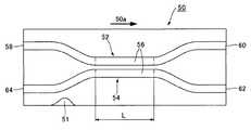
従来から知られている代表的な方向性光結合器を図8に示す。図8は、従来の方向性光結合器の概略的な平面図である。図8に示す方向性光結合器50は、図8の面と平行に配置された基板51と、基板51の上に積層された第1の光導波路52及び第2の光導波路54を有している。第1の光導波路52及び第2の光導波路54はそれぞれ、光の伝搬方向50aと垂直な方向に互いに近接して配置された直線部分56を有し、この直線部分56により、光結合部を構成している。第1の光導波路52は、第1の入射ポート58と、第2の出射ポート60とを有し、第2の光導波路54は、第3の出射ポート62と、第4の入射ポート64とを有している。また、方向性光結合器50の結合長さLを、直線部分56の長さとする。 A typical directional optical coupler conventionally known is shown in FIG. FIG. 8 is a schematic plan view of a conventional directional optical coupler. A directional
第1の入射ポート58から光を伝搬させると、光の強度の大きい箇所が光の伝搬方向50aに沿って一定の干渉周期で交互に第1の光導波路52と第2の光導波路54に発生する。例えば、光の強度の大きい箇所が第2の光導波路54になる所定の結合長さにおいては、大部分の光は、第3の出射ポート62に伝搬され、一部分の光は、クロストークとして第2の出射ポート60に漏れる。従って、方向性光結合器では、結合長さLを調整することで、第2出射ポート60と第3出射ポート62へ出力する光の分岐比を選択することができる。また、光は、基板に対して平行な偏波成分TEと、基板に対して垂直な偏波成分TMとを有している。 When light is propagated from the
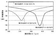
図9は、各偏波成分のクロストークを示すグラフである。図9のグラフにおいて、横軸は、結合長さの半分であり、縦軸は、過剰損失である。図9は、第1の入射ポート58から伝搬した光のほとんどが第3の出射ポート62へ出力される状態を示している。この場合、第2の出射ポート60では、出力される光がクロストーク成分となるため、過剰損失が大きい(負のデシベル値における絶対値が大きい)方が好ましく、第3の出射ポート62では、過剰損失が小さい(デシベル値が0に近い)方が好ましい。図9から分かるように、第3の出射ポート62における偏波成分TE、TMの過剰損失は、結合長さが変化してもほぼ変わらない。これに対して、第2の出射ポート60における偏波成分TE、TMの過剰損失(クロストーク)は、第2の出射ポート60へ極わずかな光が伝搬してくるため、偏波成分による位相ずれの影響を大きく受けることになる。例えば、一方の偏波成分TEの過剰損失を最小にする結合長さを選択するとき、他方の偏波成分TMの過剰損失は最小にならない。従って、第2の出射ポート60における偏波成分TE、TMの過剰損失を両方とも、−25dBよりも小さくすることはできない。 FIG. 9 is a graph showing crosstalk of each polarization component. In the graph of FIG. 9, the horizontal axis represents half of the coupling length, and the vertical axis represents excess loss. FIG. 9 shows a state where most of the light propagated from the
特許文献1には、過剰損失の偏波による変動を緩和するために、互いに近接した直線光導波路の幅が異なっている方向性結合器が開示されている。また、幅が狭い方の直線光導波路の両側には、入射ポート及び出射ポートにおける光導波路の幅を共通にするためのテーパ光導波路が、直線光導波路と同軸に設けられている。 Patent Document 1 discloses a directional coupler in which the widths of linear optical waveguides close to each other are different in order to reduce fluctuations due to polarization of excess loss. Further, on both sides of the narrower linear optical waveguide, tapered optical waveguides for making the width of the optical waveguides common to the incident port and the outgoing port are provided coaxially with the linear optical waveguide.
上述したクロストークをできるだけ小さくすることが望ましい。クロストークを小さくするためには、各偏波成分TE、TMの位相を変化させ、互いに近づけることが考えられる。
また、特許文献1に開示されている方向性光結合器は、互いに近接した直線光導波路の幅が異なり、方向性光結合器として非対称であるので、第1の入射ポート58から光を入射したときに第3の出射ポート62へ全て光を伝搬させる0:100%分岐比をとる回路を得ることが難しい。この文献のような直線光導波路の幅が異なる方向性結合器は、数10%の分岐を広帯域で歩留まりよく得るために使用されるものである。詳細には、結合長さに対する各出力ポートの強度遷移曲線(sine曲線)の振幅を小さくし、振幅の上端と下端を利用しているので、偏波依存性があっても影響が少なくなる。従って、直線光導波路の幅が異なる構造は、偏波の影響を受けにくいだけであり、偏波成分に応じて異なる干渉長の長さ自体を調整するものではない。It is desirable to make the above-described crosstalk as small as possible. In order to reduce the crosstalk, it is conceivable to change the phases of the polarization components TE and TM so as to be close to each other.
In addition, the directional optical coupler disclosed in Patent Document 1 has different widths of linear optical waveguides close to each other and is asymmetric as a directional optical coupler, so that light is incident from the
そこで、本発明の目的は、伝搬光の偏波成分の位相特性を変化させることができる方向性光結合器を提供することにある。 Accordingly, an object of the present invention is to provide a directional optical coupler capable of changing the phase characteristic of the polarization component of propagating light.
上記目的を達成するために、本発明による方向性光結合器は、光結合部を形成するために互いに近接して長手方向に延びるコアとその中心線とを有する2つの直線光導波路と、少なくとも一方の直線光導波路のコアに連結されたコアを有するテーパ光導波路と、を有し、テーパ光導波路のコアの幅は、少なくとも一方の直線光導波路に向かって狭まり、テーパ光導波路の形状は、少なくとも一方の直線光導波路のコアの中心線に対して非対称であることを特徴としている。 In order to achieve the above object, a directional optical coupler according to the present invention includes at least two linear optical waveguides having a core extending in the longitudinal direction adjacent to each other to form an optical coupling portion and a center line thereof, and at least A tapered optical waveguide having a core coupled to the core of one of the linear optical waveguides, the width of the core of the tapered optical waveguide narrows toward at least one of the linear optical waveguides, and the shape of the tapered optical waveguide is It is characterized by being asymmetric with respect to the center line of the core of at least one of the straight optical waveguides.
このように構成された本発明による方向性光結合器によれば、テーパ光導波路を通って伝搬してきた光は、光結合部を形成するために互いに近接した2つの直線導波路の一方の直線光導波路に入り、その後、所定の干渉周期に従って、2つの直線導波路を交互に乗り移りながら伝搬する。光は、互いに垂直な2つの偏波成分を有している。光結合部を形成するために互いに近接して長手方向に延びるコアとその中心線とを有する2つの直線光導波路と、直線光導波路のコアの中心線に対して非対称な形状のテーパ光導波路とを有する構造にすること、及び、2つの直線導波路のコアの幅を調整し且つ2つの直線光導波路のコア間の距離を調整することによって、光の2つの偏波成分の間の位相を変化させ、それにより、伝搬光の偏波成分の位相特性を変化させることができる。その結果、偏波による過剰損失の変動を緩和することができる。 According to the directional optical coupler of the present invention configured as described above, the light propagating through the tapered optical waveguide is one straight line of two linear waveguides close to each other to form an optical coupling portion. It enters the optical waveguide, and then propagates while alternately passing through the two linear waveguides according to a predetermined interference period. The light has two polarization components perpendicular to each other. Two linear optical waveguides having a core extending in the longitudinal direction adjacent to each other to form an optical coupling portion, and a taper optical waveguide having an asymmetric shape with respect to the center line of the core of the linear optical waveguide; And adjusting the width of the cores of the two linear waveguides and the distance between the cores of the two linear optical waveguides to adjust the phase between the two polarization components of the light. Thus, the phase characteristics of the polarization component of the propagation light can be changed. As a result, fluctuations in excess loss due to polarization can be mitigated.
本発明による方向性光結合器において、好ましくは、直線光導波路のコアの幅及び2つの直線導波路のコア間の距離は、Vパラメータ及び結合係数により決定される。 In the directional optical coupler according to the present invention, preferably, the width of the core of the linear optical waveguide and the distance between the cores of the two linear waveguides are determined by the V parameter and the coupling coefficient.
このように構成された方向性光結合器では、伝搬光の波長を変えたとき、2つの直線導波路のコアの幅及び2つの直線光導波路のコア間の距離を容易に決定することができる。 In the directional optical coupler configured as described above, when the wavelength of propagating light is changed, the width of the cores of the two linear waveguides and the distance between the cores of the two linear optical waveguides can be easily determined. .
この方向性光結合器において、テーパ光導波路の境界線の少なくとも一部分は直線であってもよいし、曲線であってもよい。 In this directional optical coupler, at least a part of the boundary line of the tapered optical waveguide may be a straight line or a curved line.
本発明の方向性光結合器により、伝搬光の偏波成分の位相特性を変化させることができる。 With the directional optical coupler of the present invention, the phase characteristic of the polarization component of the propagation light can be changed.
以下、図面を参照して、本発明による方向性光結合器の第1の実施形態を説明する。図1は、本発明による第1の実施形態である方向性光結合器の概略的な平面図である。 Hereinafter, a first embodiment of a directional optical coupler according to the present invention will be described with reference to the drawings. FIG. 1 is a schematic plan view of a directional optical coupler according to a first embodiment of the present invention.
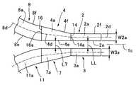
図1に示すように、方向性光結合器1は、光結合部を形成するために互いに近接して長手方向1aに延びる2つの直線光導波路2、3と、2つの直線光導波路2、3の両側にテーパ光導波路4、5、6、7を介して接続された4つの入出力光導波路である曲線光導波路8、9、10、11とを有し、これらの光導波路2〜11は、図1の面と平行に配置された基板12の上に積層されている。詳細には、各光導波路2〜11はそれぞれ、コア2a〜11aと、その周りに配置されたクラッド13とを有しており、コア2a〜11aとクラッド13は、Si又はガラス基板等の基板12の上にポリマー等を積層することによって形成されている。第1の直線光導波路2のコア2aの一方の端部2bは、テーパ光導波路4のコア4aを介して第1の曲線光導波路8のコア8aに連結され、他方の端部2cは、テーパ光導波路5のコア5aを介して第2の曲線光導波路9のコア9aに連結されている。同様に、第2の直線光導波路3のコア3aの端部3cは、テーパ光導波路6のコア6aを介して第3の曲線光導波路10のコア10aに連結され、他方の端部3bは、テーパ光導波路7のコア7aを介して第4の曲線光導波路11のコア11aに接続されている。第1の曲線光導波路8は、第1の入射ポート8pを有し、第2の曲線光導波路9及び第3の曲線光導波路10はそれぞれ、第2の出射ポート9p及び第3の出射ポート10pを有している。また、本実施形態において、光結合部の結合長さLは、直線光導波路2、3の長さとする。なお、第1の曲線光導波路8及び第4の曲線光導波路11は、長手方向1aにおいて同じ側にある。 As shown in FIG. 1, the directional optical coupler 1 includes two linear
本実施形態の方向性結合器1は、長手方向1aに延びる軸線1c及びそれと垂直に幅方向1bに延びる軸線1dに対して対称に形成されている。従って、以下、図2を参照して、第1の曲線光導波路8、テーパ導波路4及び第1の直線光導波路2について説明し、その他の光導波路の説明を省略する。 The directional coupler 1 of the present embodiment is formed symmetrically with respect to an
図2は、テーパ光導波路4及びその周囲の概略的な拡大平面図である。図2に示すように、テーパ光導波路4のコア4aの幅は、直線光導波路2に向かって狭まっている。即ち、直線光導波路2のコア2aの幅は、曲線光導波路8のコアの幅8aよりも狭くなっている。なお、本実施形態では、直線光導波路2、3のコア2a、3aの幅W2a、W3aは等しく、曲線光導波路8〜11のコア8a〜11aの幅は等しい。 FIG. 2 is a schematic enlarged plan view of the tapered optical waveguide 4 and its surroundings. As shown in FIG. 2, the width of the
また、第1の直線光導波路2のコア2aは、その中心線2dと、第2の直線光導波路3側の境界線2eと、それと反対側の境界線2fとを有している。また、テーパ光導波路4のコア4aは、第1の直線光導波路2の境界線2e、2fのそれぞれと接続された境界線4e、4fを有し、曲線光導波路8のコア8aは、テーパ光導波路4の境界線4e、4fのそれぞれと接続された境界線8e、8fを有している。 The core 2a of the first linear
直線光導波路2の境界線2e、2fは直線である。また、テーパ光導波路4のコア4aは、直線光導波路2のコア2aの中心線2dに対して非対称な平面形状を有している。具体的には、テーパ光導波路4の境界線4e、4fは直線であり、境界線4eは、直線光導波路2の境界線2eと同一直線上に配置され、境界線4fは、境界線2fと一定の角度をなして接続されている。 The
また、直線光導波路2のコア2aとテーパ光導波路4のコア4aとの間に仮想の第1の仕切り線、即ち、光学的な接続面14を設け、テーパ光導波路4のコア4aと曲線光導波路8のコア8aとの間に仮想の第2の仕切り線、即ち、光学的な接続面16を設け、第1の仕切り線14の中点14aと第2の仕切り線16の中点16aを結ぶ直線をテーパ光導波路4のコア4aの中心線4dとする。テーパ光導波路4のコア4aの中心線4dは、直線光導波路2のコア2aの中心線2dと一定の角度をなして接続される。また、曲線光導波路8とテーパ光導波路4の光学的な接続面16において、波面を整合させるために、曲線光導波路8のコア8aの中心線8dの接線の傾きとテーパ光導波路4のコア4aの中心線4dの傾きとが一致していることが好ましい。 Further, a virtual first partition line, that is, an
第2の直線光導波路3、第4の曲線光導波路11、及びそれらの間のテーパ光導波路7はそれぞれ、軸線1cに対して第1の直線光導波路2、第1の曲線光導波路8、及びテーパ光導波路4と対称に形成されている。第1の直線光導波路2のコア2aと第2の直線光導波路3のコア3aとの間の幅方向1bの距離LL、及び、テーパ光導波路4のコア4aとテーパ光導波路7のコア7aとの間の幅方向1bの距離LTは、軸線1cの方向に一定である。 The second linear
第1の直線光導波路2のコア2aのコア幅W2a及び第1の直線光導波路2のコア2aと第2の直線光導波路3のコア3aとの間の幅方向1bの距離LLを決定する第1の方法は、伝搬光の偏波成分の所望の位相特性を得るように、コア幅W2a及び距離LLを試行錯誤により決定する方法である。例えば、波長1550nmの光を方向性結合器に伝搬させたときの偏波成分の位相が同じになるように、コア幅W2a及び距離LLをそれぞれ、3μm、3.5μmに決定した。 The core width W2a of the core 2a of the first linear
コア幅W2a及び距離LLを決定する第2の方法は、光導波路パラメータを規格化したVパラメータ及び結合係数Kを用いて算出する方法である。VパラメータVは、式(1)で表わされ、結合係数Kは、式(2)で表される。
第2の方法の一例を具体的に説明する。まず、所定の波長λにおける幅W2a及び距離LLを試行錯誤により決定する。
次いで、各光導波路パラメータ、即ち、所定の波長λ、コア幅W2a、コアの屈折率n1、及び比屈折率差Δを式(1)に代入してVパラメータを計算する。例えば、波長λが1.55μm(1550nm)の場合、W2a=3μm、n1=1.527、Δ=0.004(0.4%)を式(1)に代入し、Vパラメータ値0.82を得る。次いで、異なる波長におけるコア幅W2aを計算するために、得られたVパラメータ値、コアの屈折率n1及び比屈折率差Δを式(1)に代入する。例えば、方向性結合器に伝搬する光の波長λが1.31μm(1310nm)の場合、Vパラメータ値0.82と、波長1.31μm(1310nm)におけるコアの屈折率n1、比屈折率差Δを式(1)に代入することにより、コア幅W2a=2.5μmを計算する。An example of the second method will be specifically described. First, the width W2a and distance LL at a predetermined wavelength λ are determined by trial and error.
Next, each optical waveguide parameter, that is, a predetermined wavelength λ, a core width W2a, a core refractive index n1 , and a relative refractive index difference Δ is substituted into Equation (1) to calculate a V parameter. For example, when the wavelength λ is1.55 μm( 1550 nm) , W2a = 3 μm, n1 = 1.527, Δ =0.004 ( 0.4%) is substituted into the equation (1), and the
また、各光導波路パラメータ、即ち、所定の波長におけるコア幅W2a及び距離LL、伝搬定数β、コアの屈折率n1、及びクラッド13の屈折率n3を式(2)〜式(4)に代入して、結合係数Kを計算する。例えば、波長λが1.55μm(1550nm)の場合、W2a=3μm、LL=3.5μm、β=6.17μm-1、n1=1.527、n3=1.521を式(2)〜式(4)に代入し、結合係数K=0.0092を得る。次いで、異なる波長における距離LLを計算するために、得られた結合係数K、先に計算されたコア幅W2a、伝搬定数β、コアの屈折率n1、及びクラッド13の屈折率n3を式(2)〜式(4)に代入する。例えば、方向性結合器に伝搬する光の波長λが1.31μm(1310nm)の場合、結合係数K=0.0092μm-1、W2a=3μm、β、n1、n3は前と同じ値を式(2)〜式(4)に代入することにより、距離LLを計算する。Also, each optical waveguide parameter, that is, the core width W2a and distance LL at a predetermined wavelength, the propagation constant β, the refractive index n1 of the core, and the refractive index n3 of the clad 13 are expressed by equations (2) to (4). Substituting and calculating the coupling coefficient K. For example, when the wavelength λ is1.55 μm( 1550 nm) , W2a = 3 μm, LL = 3.5 μm, β = 6.17μm−1 , n1 = 1.527, and n3 = 1.521 ) To Expression (4) to obtain a coupling coefficient K = 0.0002. Next, in order to calculate the distance LL at different wavelengths, the obtained coupling coefficient K, the previously calculated core width W2a, the propagation constant β, the refractive index n1 of the core, and the refractive index n3 of the
予めVパラメータ値V及び結合係数Kが分かっていれば、試行錯誤によりコア幅W2a及び距離LLを決定することを省略することができる。 If the V parameter value V and the coupling coefficient K are known in advance, the determination of the core width W2a and the distance LL by trial and error can be omitted.
次に、本発明の第1の実施形態による方向性光結合器の動作を説明する。
第1の曲線光導波路8に光を入射すると、テーパ光導波路4を介して直線導波路2に伝搬される。次いで、光は、所定の干渉周期に従って、2つの直線導波路2、3を交互に乗り移りながら長手方向に伝搬し、第2の曲線光導波路9及び/又は第3の曲線光導波路10から出射される。Next, the operation of the directional optical coupler according to the first embodiment of the present invention will be described.
When light enters the first curved
テーパ光導波路4の平面形状が直線光導波路2のコア2aの中心線2dに対して非対称構造をなしている又は、テーパ光導波路4のコア4aの中心線4dと直線光導波路2のコア2aの中心線2dとが一定の角度をなしている構造を有し、且つ、試行錯誤により又はVパラメータ及び結合係数Kにより得られる直線導波路2の形状を有する方向性光結合器では、光がテーパ光導波路4から直線光導波路2に入ることにより、基板12に対して平行な偏波成分TEと、基板12に対して垂直な偏波成分TMとの間の位相が変化する。例えば、偏波成分TE、TM間の位相が近づけられる。それにより、伝搬光の偏波成分の位相特性を変化させることができる。
その結果、例えば、第1の曲線光導波路8から第3の曲線光導波路10に光を伝搬させる場合、第2の曲線光導波路9の出口における偏波成分TE、TMの位相を一致させることができ、それにより、クロストークを低減させることができる。The planar shape of the tapered optical waveguide 4 has an asymmetric structure with respect to the
As a result, for example, when light is propagated from the first curved
また、試行錯誤により得られたコア幅W2a及び距離LLを有する方向性光結合器の位相特性においても、かかるコア幅W2a及び距離LLと規格化されたVパラメータ値及び結合係数Kとを使用することによって計算されたコア幅W2a及び距離LLを有する方向性光結合器の位相特性においても、第2の曲線光導波路9の出口における偏波成分TE、TMの位相を一致させることができた。かくして、方向性光結合器に伝搬する光の波長に応じた光結合部の形状を、規格化されたVパラメータ値及び結合係数Kを使用することによって決定することができる。 Further, in the phase characteristics of the directional optical coupler having the core width W2a and the distance LL obtained by trial and error, the core width W2a and the distance LL, the standardized V parameter value, and the coupling coefficient K are used. Even in the phase characteristics of the directional optical coupler having the core width W2a and the distance LL calculated as described above, the phases of the polarization components TE and TM at the exit of the second curved optical waveguide 9 could be matched. Thus, the shape of the optical coupling unit corresponding to the wavelength of light propagating to the directional optical coupler can be determined by using the standardized V parameter value and the coupling coefficient K.
また、曲線光導波路8とテーパ光導波路4の光学的な接続面16では、曲線光導波路8のコア8aの中心線8dの傾きとテーパ光導波路4のコア4aの中心線4dの傾きを一致させ、それにより、波面を整合させるので、曲線光導波路8からテーパ光導波路4へ光が伝搬する際に発生する損失を抑えることができる。 In addition, at the
次に、本発明による方向性光結合器の第2及び第3の実施形態を説明する。第2及び第3の実施形態は、主として、テーパ光導波路2の平面形状が異なること以外、第1の実施形態と同様であるので、異なる部分だけを説明し、その他の説明を省略する。 Next, second and third embodiments of the directional optical coupler according to the present invention will be described. The second and third embodiments are mainly the same as the first embodiment except that the planar shape of the tapered
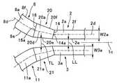
図3は、本発明による第2の実施形態のテーパ光導波路及びその周囲を示す平面図である。図3に示すように、テーパ光導波路20は、コア20aと、直線光導波路2の境界線2e、2fのそれぞれと接続された境界線20e、20fとを有している。テーパ光導波路20のコア20aは、直線光導波路2のコア2aの中心線2dに対して非対称な平面形状を有している。具体的には、テーパ光導波路20の境界線20e、20fは直線であり、境界線20e、20fはそれぞれ、直線光導波路2の境界線2e、2fと一定の角度をなして接続されている。テーパ光導波路20の境界線20eは、第1の曲線光導波路8に向かって軸線1cへ近づくように接続されていてもよいし、軸線1cから遠ざかるように接続されていてもよい。安定した分岐比を実現する場合、図3に示すように、軸線1cから遠ざかるように接続するのが好ましい。 FIG. 3 is a plan view showing a tapered optical waveguide according to the second embodiment of the present invention and its periphery. As shown in FIG. 3, the tapered
また、直線光導波路2のコア2aとテーパ導波路20のコア20aとの間に仮想の第1の仕切り線14を設け、テーパ導波路20のコア20aと曲線導波路8のコア8aとの間に仮想の第2の仕切り線16を設け、第1の仕切り線14の中点14aと第2の仕切り線16の中点16aを結ぶ直線をテーパ光導波路20のコア20aの中心線20dとする。テーパ光導波路20のコア20aの中心線20dは、直線光導波路2のコア2aの中心線2dと一定の角度をなして接続される。 A virtual
第2の直線光導波路3、第4の曲線光導波路11、及びそれらの間のテーパ光導波路21はそれぞれ、軸線1cに対して第1の直線光導波路2、第1の曲線光導波路8、及びテーパ光導波路21と対称に形成されている。第1の直線光導波路2のコア2aと第2の直線光導波路3のコア3aとの間の幅方向1bの距離LLは軸線1cの方向に一定である。テーパ光導波路20のコア20aとテーパ光導波路21のコア21aとの間の幅方向1bの距離LTは、狭すぎると干渉長がバラツキやすい傾向にあるので、安定した干渉長を得る観点では、距離LTは、距離LLに対して同等程度以上であることが好ましい。また、安定した分岐比を得るために、距離LTは、第1の曲線光導波路8及び第4の曲線光導波路11に向かって大きくなっていることが好ましい。 The second linear
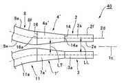
図4は、本発明による第3の実施形態のテーパ光導波路及びその周囲を示す平面図である。図3に示すように、テーパ光導波路30は、コア30aと、直線光導波路2の境界線2e、2fのそれぞれと接続された境界線30e、30fとを有している。テーパ光導波路30のコア30aは、直線光導波路2のコア2aの中心線2dに対して非対称な平面形状を有している。具体的には、テーパ光導波路30の境界線30e、30fは、同じ向きに湾曲した曲線である。 FIG. 4 is a plan view showing a tapered optical waveguide according to a third embodiment of the present invention and its periphery. As illustrated in FIG. 3, the tapered
また、直線光導波路2のコア2aとテーパ導波路30のコア30aとの間に仮想の第1の仕切り線14を設け、テーパ光導波路30のコア30aと曲線導波路8のコア8aとの間に仮想の第2の仕切り線16を設け、第1の仕切り線14の中点14aと第2の仕切り線16の中点16aとの間のテーパ光導波路30の幅中心を結ぶ曲線をテーパ光導波路30のコア30aの中心線30dとする。テーパ光導波路30のコア30aの中心線30dの中点14aにおける接線30d’は、直線光導波路2のコア2aの中心線2dと一定の角度をなしている。 A virtual
第2の直線光導波路3、第4の曲線光導波路11、及びそれらの間のテーパ光導波路30はそれぞれ、軸線1cに対して第1の直線光導波路2、第1の曲線光導波路8、及びテーパ光導波路31と対称に形成されている。 The second linear
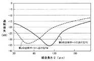
図5は、本発明の第1の実施形態による方向性光結合器における偏波成分によるクロストークの違いを示すグラフである。図5のグラフにおいて、横軸は、結合長さの半分の長さであり、縦軸は、過剰損失である。図5は、大部分の光が第1の入射ポート8pから第3の出射ポート10pに伝搬されている状態を示している。図5から分かるように、第3の出射ポート10pにおける偏波成分TE、TMの過剰損失は、結合長さが変化してもほぼ変わらない。これに対して、第2の出射ポート9pにおける偏波成分TE、TMの過剰損失(クロストーク)は、結合長さの変化により変化するが、両者の位相はほぼ一致している。従って、偏波成分TEの過剰損失を最小にする結合長さを選択すれば、偏波成分TMの過剰損失も最小になり、両方の偏波成分TE、TMについて、第2の出射ポート9pにおける過剰損失を−25dBよりも小さくすることができた。 FIG. 5 is a graph showing a difference in crosstalk due to polarization components in the directional optical coupler according to the first embodiment of the present invention. In the graph of FIG. 5, the horizontal axis is half the coupling length, and the vertical axis is excess loss. FIG. 5 shows a state in which most of the light is propagated from the first incident port 8p to the third exit port 10p. As can be seen from FIG. 5, the excess loss of the polarization components TE and TM at the third output port 10p does not change substantially even if the coupling length changes. On the other hand, the excess loss (crosstalk) of the polarization components TE and TM at the second output port 9p changes due to the change in the coupling length, but the phases of both are almost the same. Therefore, if a coupling length that minimizes the excess loss of the polarization component TE is selected, the excess loss of the polarization component TM is also minimized, and both polarization components TE and TM are obtained at the second output port 9p. The excess loss could be made smaller than -25 dB.
次に、テーパ光導波路が直線光導波路のコアの中心線に対して対称である方向性光結合器を、本発明による方向性光結合器の比較例として説明する。図6は、比較例の方向性光結合器のテーパ光導波路及びその周囲の概略的な拡大平面図である。比較例の方向性光結合器40は、図1及び図2に示した方向性光結合器1と比較して、直線光導波路2、3のコア2a、3aの中心線2d(コア3aの中心線の符号は省略)に対して対称なテーパ光導波路4’〜7’(5’及び6’は図示せず)を採用したこと以外、方向性光結合器1と同様の構造を有している。テーパ導波路4’のコア4a’とテーパ光導波路7’のコア7a’との間の幅方向1bの距離LTは、第1の曲線光導波路8及び第4の曲線光導波路11に向かって小さくなっている。 Next, a directional optical coupler in which the tapered optical waveguide is symmetric with respect to the center line of the core of the linear optical waveguide will be described as a comparative example of the directional optical coupler according to the present invention. FIG. 6 is a schematic enlarged plan view of the tapered optical waveguide of the directional optical coupler of the comparative example and its surroundings. Compared to the directional optical coupler 1 shown in FIGS. 1 and 2, the directional
図7は、図6に示した比較例の方向性光結合器における偏波成分によるクロストークの違いを示したグラフである。図5と同様、図7の横軸は、結合長さの半分の長さであり、縦軸は、過剰損失であり、大部分の光が第1の入射ポート8pから第3の出射ポート10pに伝搬している状態を示している。クロストークは、第2の出射ポート9pへ伝搬する光量を示す。図7から分かるように、比較例の方向性光結合器40の第2の出射ポート9pにおける偏波成分TE、TMは、その位相調整を十分に試みても、結合長さが異なってしまう。
このように、テーパ光導波路4’〜7’が直線光導波路2、3のコア2a、3aの中心線2d(コア3aの中心線の符号は省略)に対して対称である構造では、テーパ導波路4’のコア4a’とテーパ光導波路7’のコア7a’との間の幅方向1bの距離LTを確保する必要がある。従って、第1の直線光導波路2のコア2aと第2の直線光導波路3のコア3aとの間の幅方向1bの距離LLは、所望の位相特性を得るためにVパラメータ及び結合係数Kから算出される距離LLよりも大きくなる。その結果、クロストークに偏波依存性がでてしまう。FIG. 7 is a graph showing differences in crosstalk due to polarization components in the directional optical coupler of the comparative example shown in FIG. As in FIG. 5, the horizontal axis of FIG. 7 is half the coupling length, the vertical axis is excess loss, and most of the light is transmitted from the first incident port 8p to the third output port 10p. Shows the state of propagation. Crosstalk indicates the amount of light propagating to the second exit port 9p. As can be seen from FIG. 7, the polarization components TE and TM at the second output port 9p of the directional
As described above, in the structure in which the tapered optical waveguides 4 ′ to 7 ′ are symmetrical with respect to the
以上、本発明の実施形態を説明したが、本発明は、以上の実施の形態に限定されることなく、特許請求の範囲に記載された発明の範囲内で種々の変更が可能であり、それらも本発明の範囲内に包含されるものであることはいうまでもない。
上記実施形態では、各テーパ光導波路4〜7の平面形状が同じである場合を説明したが、光の偏波成分の調整に応じて、それらの平面形状を変えてもよい。
また、上記第2の実施形態では、距離LTが、第1の曲線光導波路8及び第4の曲線光導波路11に向かって大きくなっていたけれども、安定した分岐比が得られれば、小さくなっていてもよい。Although the embodiments of the present invention have been described above, the present invention is not limited to the above-described embodiments, and various modifications are possible within the scope of the invention described in the claims. Needless to say, these are also included within the scope of the present invention.
In the above-described embodiment, the case where the planar shapes of the tapered optical waveguides 4 to 7 are the same has been described. However, the planar shapes may be changed according to the adjustment of the polarization component of light.
In the second embodiment, the distance LT increases toward the first curved
1 方向性光結合器
2、3 直線光導波路
2a、3a コア
2d 中心線
5、6、7、8、20、30 テーパ光導波路
5a、6a、7a、8a、20a、30a コア
5e、5f、20e、20f、30e、30f 境界線DESCRIPTION OF SYMBOLS 1 Directional
Claims (2)
Translated fromJapanese最初に、前記方向性光結合器から出力される或る波長の光の互いに垂直な偏波成分の位相が同じになるように、前記或る波長における前記コアの幅W2a及び前記距離LLを試行錯誤により決定し、
前記或る波長における前記コアの幅W2a及び前記距離LLと、次式(1)〜式(4)
計算されたVパラメータ値Vを式(1)に代入することにより、別の波長における前記コアの幅W2aを計算し、次いで、計算された結合係数Kと、計算された前記別の波長における前記コアの幅W2aを式(2)に代入し、式(2)〜式(4)より、前記別の波長における前記距離LLを計算し、
ここで、λは伝搬する光の波長、n1はコアの屈折率、Δは比屈折率差、βは、2本の直線光導波路のうち1つが単独で存在する場合のモードの伝搬定数、k0=2π/λ、n3は2本の直線導波路のコア間に介在するクラッドの屈折率であることを特徴とする、方法。Tapered light having two linear optical waveguides having a core extending in the longitudinal direction adjacent to each other and a center line thereof in order to form an optical coupling portion, and a core connected to the core of at least one of the linear optical waveguides A width of the core of the tapered optical waveguide narrows toward the at least one linear optical waveguide, and the shape of the tapered optical waveguide is in relation to the center line of the core of the at least one linear optical waveguide. In a directional optical coupler that is asymmetric, a method of calculating a core width W2a of the linear optical waveguide and a distance LL between the cores of the two linear waveguides,
First, the core width W2a and the distance LL at the certain wavelength are tried so that the phases of polarization components perpendicular to each other of the light of the certain wavelength output from the directional optical coupler are the same. Determined by mistakes,
The core width W2a and the distance LL at the certain wavelength, and the following equations (1) to (4)
Substituting the calculated V parameter value V into equation (1) to calculatethe width W2a of thecore at another wavelength, and then calculating the calculated coupling coefficient K and the calculated at the other wavelength. Substituting the width W2a of the core into the equation (2), and calculating the distance LL at the other wavelength from the equations (2) to (4),
Where λ is the wavelength of the propagating light, n1 is the refractive index of the core, Δ is the relative refractive index difference, β is the propagation constant of the mode when one of the two linear optical waveguides exists alone, k0 = 2π / λ, where n3 is the refractive index of the cladding interposed between the cores of the two linear waveguides.
Priority Applications (2)
| Application Number | Priority Date | Filing Date | Title |
|---|---|---|---|
| JP2005346180AJP4636439B2 (en) | 2005-11-30 | 2005-11-30 | Calculation method of core width and distance between cores of two linear optical waveguides of directional optical coupler |
| US11/605,289US7546014B2 (en) | 2005-11-30 | 2006-11-29 | Optical directional coupler |
Applications Claiming Priority (1)
| Application Number | Priority Date | Filing Date | Title |
|---|---|---|---|
| JP2005346180AJP4636439B2 (en) | 2005-11-30 | 2005-11-30 | Calculation method of core width and distance between cores of two linear optical waveguides of directional optical coupler |
Publications (2)
| Publication Number | Publication Date |
|---|---|
| JP2007148290A JP2007148290A (en) | 2007-06-14 |
| JP4636439B2true JP4636439B2 (en) | 2011-02-23 |
Family
ID=38087627
Family Applications (1)
| Application Number | Title | Priority Date | Filing Date |
|---|---|---|---|
| JP2005346180AExpired - Fee RelatedJP4636439B2 (en) | 2005-11-30 | 2005-11-30 | Calculation method of core width and distance between cores of two linear optical waveguides of directional optical coupler |
Country Status (2)
| Country | Link |
|---|---|
| US (1) | US7546014B2 (en) |
| JP (1) | JP4636439B2 (en) |
Families Citing this family (11)
| Publication number | Priority date | Publication date | Assignee | Title |
|---|---|---|---|---|
| JP2014041175A (en)* | 2012-08-21 | 2014-03-06 | Oki Electric Ind Co Ltd | Wavelength selective optical route switching device |
| WO2017169922A1 (en)* | 2016-03-28 | 2017-10-05 | 日本電気株式会社 | Polarization beam splitter |
| CN106680935B (en)* | 2016-11-24 | 2019-03-05 | 中国电子科技集团公司第五十五研究所 | Efficient coupling structure and production method between a kind of silicon substrate optical waveguide |
| US20190250329A1 (en)* | 2018-02-15 | 2019-08-15 | Nokia Solutions And Networks Oy | Optical Waveguide Processors For Integrated Optics |
| WO2020018657A1 (en)* | 2018-07-17 | 2020-01-23 | Commscope Technologies Llc | Fiber optical communication system using asymmetric optical waveguide splitter |
| CN113009621B (en)* | 2019-12-19 | 2024-09-24 | 中兴光电子技术有限公司 | Directional coupler and beam splitter thereof |
| JP7468102B2 (en) | 2020-04-15 | 2024-04-16 | 富士通オプティカルコンポーネンツ株式会社 | Optical Waveguide Device |
| CN112711093B (en)* | 2021-03-26 | 2021-07-20 | 西安奇芯光电科技有限公司 | Polarization beam splitter structure and polarization beam splitting method |
| US20240241314A1 (en)* | 2023-01-13 | 2024-07-18 | Globalfoundries U.S. Inc. | Directional couplers with heterogenous claddings |
| CN116400460B (en)* | 2023-05-10 | 2025-09-23 | 兰州大学 | Polarization-independent directional coupler based on subwavelength grating structure |
| CN117289390B (en)* | 2023-09-15 | 2024-08-06 | 深圳技术大学 | On-chip integrated polarization beam splitter based on silicon nitride ridge optical waveguide |
Family Cites Families (10)
| Publication number | Priority date | Publication date | Assignee | Title |
|---|---|---|---|---|
| US4151747A (en)* | 1978-06-21 | 1979-05-01 | Electric Power Research Institute, Inc. | Monitoring arrangement utilizing fiber optics |
| JP3104818B2 (en)* | 1992-08-28 | 2000-10-30 | 日本電信電話株式会社 | Optical directional coupler |
| JPH06308338A (en) | 1993-04-23 | 1994-11-04 | Furukawa Electric Co Ltd:The | Waveguide type optical component |
| FI944253A7 (en)* | 1993-09-17 | 1995-03-18 | Iot Integrierte Optik Gmbh | Integrated optical 2 x 2 switch |
| JP3225819B2 (en)* | 1995-12-26 | 2001-11-05 | 日立電線株式会社 | Waveguide type optical branching device |
| WO1998029768A1 (en)* | 1996-12-31 | 1998-07-09 | Corning Incorporated | Optical couplers with multilayer fibers |
| US6134362A (en)* | 1998-06-04 | 2000-10-17 | U.S.A. Kaifa Technology, Inc. | Short length fused fiber optical couplers and method of making same |
| JP4086485B2 (en)* | 2001-07-23 | 2008-05-14 | 日本電信電話株式会社 | Polarization-independent directional coupler and optical circuit using the same |
| JP3952944B2 (en)* | 2002-08-30 | 2007-08-01 | Kddi株式会社 | Ring resonant circuit |
| JP3883118B2 (en)* | 2002-10-29 | 2007-02-21 | 日本電信電話株式会社 | Optical directional coupler and manufacturing method of optical directional coupler |
- 2005
- 2005-11-30JPJP2005346180Apatent/JP4636439B2/ennot_activeExpired - Fee Related
- 2006
- 2006-11-29USUS11/605,289patent/US7546014B2/ennot_activeExpired - Fee Related
Also Published As
| Publication number | Publication date |
|---|---|
| US20070122080A1 (en) | 2007-05-31 |
| US7546014B2 (en) | 2009-06-09 |
| JP2007148290A (en) | 2007-06-14 |
Similar Documents
| Publication | Publication Date | Title |
|---|---|---|
| US6563988B2 (en) | Optical apparatus and method having predetermined group velocity dispersion | |
| US8064741B2 (en) | Optical coupling device | |
| US9835798B2 (en) | Planar optical waveguide device, polarization multiplexing 4-value phase modulator, coherent receiver, and polarization diversity | |
| JP7477761B2 (en) | Mode conversion element | |
| CN100437176C (en) | Polarization Compensated Optical Splitter | |
| JP2007114253A (en) | Waveguide-type optical branching element | |
| JP6572175B2 (en) | Waveguide type optical coupler | |
| US11061187B2 (en) | Planar lightwave circuit optical splitter/mixer | |
| US7546014B2 (en) | Optical directional coupler | |
| JP3952696B2 (en) | Optical coupling structure | |
| JP2011090223A (en) | Crossing optical waveguide | |
| JP7328580B2 (en) | optical waveguide | |
| CN115931019A (en) | Multi-mode device for multiplexing and demultiplexing | |
| JP4477260B2 (en) | Waveguide-type optical coupler and optical multiplexer / demultiplexer using the waveguide-type optical coupler | |
| WO2014017154A1 (en) | Multimode interference coupler | |
| JP3795821B2 (en) | Optical splitter | |
| JP2013068908A (en) | Optical device | |
| JP5169536B2 (en) | Optical multiplexing / demultiplexing device | |
| KR100429567B1 (en) | Optical power splitter | |
| JP5880087B2 (en) | Grating element and optical element | |
| GB2395796A (en) | Optical waveguide branching component with MMI couplers | |
| JP5091072B2 (en) | Y branch optical waveguide and design method thereof | |
| EP1421422A1 (en) | Arrayed waveguide grating with reduced chromatic dispersion | |
| Cabanillas et al. | Efficient, narrow profile waveguide crossings based on rapid adiabatic coupling | |
| JP2003215373A (en) | Optical coupler and array waveguide diffraction grating comprising the same |
Legal Events
| Date | Code | Title | Description |
|---|---|---|---|
| A621 | Written request for application examination | Free format text:JAPANESE INTERMEDIATE CODE: A621 Effective date:20080613 | |
| A131 | Notification of reasons for refusal | Free format text:JAPANESE INTERMEDIATE CODE: A131 Effective date:20100118 | |
| A977 | Report on retrieval | Free format text:JAPANESE INTERMEDIATE CODE: A971007 Effective date:20100119 | |
| A521 | Request for written amendment filed | Free format text:JAPANESE INTERMEDIATE CODE: A523 Effective date:20100318 | |
| A131 | Notification of reasons for refusal | Free format text:JAPANESE INTERMEDIATE CODE: A131 Effective date:20100607 | |
| A521 | Request for written amendment filed | Free format text:JAPANESE INTERMEDIATE CODE: A523 Effective date:20100805 | |
| A131 | Notification of reasons for refusal | Free format text:JAPANESE INTERMEDIATE CODE: A131 Effective date:20100823 | |
| A521 | Request for written amendment filed | Free format text:JAPANESE INTERMEDIATE CODE: A523 Effective date:20101013 | |
| TRDD | Decision of grant or rejection written | ||
| A01 | Written decision to grant a patent or to grant a registration (utility model) | Free format text:JAPANESE INTERMEDIATE CODE: A01 Effective date:20101101 | |
| A01 | Written decision to grant a patent or to grant a registration (utility model) | Free format text:JAPANESE INTERMEDIATE CODE: A01 | |
| FPAY | Renewal fee payment (event date is renewal date of database) | Free format text:PAYMENT UNTIL: 20131203 Year of fee payment:3 | |
| A61 | First payment of annual fees (during grant procedure) | Free format text:JAPANESE INTERMEDIATE CODE: A61 Effective date:20101114 | |
| FPAY | Renewal fee payment (event date is renewal date of database) | Free format text:PAYMENT UNTIL: 20131203 Year of fee payment:3 | |
| LAPS | Cancellation because of no payment of annual fees |