Movatterモバイル変換


[0]ホーム

URL:


JP4634944B2 - lighting equipment - Google Patents

lighting equipment
Download PDF

Info

Publication number
JP4634944B2
JP4634944B2JP2006047410AJP2006047410AJP4634944B2JP 4634944 B2JP4634944 B2JP 4634944B2JP 2006047410 AJP2006047410 AJP 2006047410AJP 2006047410 AJP2006047410 AJP 2006047410AJP 4634944 B2JP4634944 B2JP 4634944B2
Authority
JP
Japan
Prior art keywords
light source
cover
main
instrument
light
Prior art date
Legal status (The legal status is an assumption and is not a legal conclusion. Google has not performed a legal analysis and makes no representation as to the accuracy of the status listed.)
Expired - Fee Related
Application number
JP2006047410A
Other languages
Japanese (ja)
Other versions
JP2007227177A (en
Inventor
恒 福田
徹 居相
浩明 小林
昭博 佐藤
成加 大槻
Current Assignee (The listed assignees may be inaccurate. Google has not performed a legal analysis and makes no representation or warranty as to the accuracy of the list.)
Panasonic Corp
Panasonic Electric Works Co Ltd
Original Assignee
Panasonic Corp
Matsushita Electric Works Ltd
Priority date (The priority date is an assumption and is not a legal conclusion. Google has not performed a legal analysis and makes no representation as to the accuracy of the date listed.)
Filing date
Publication date
Application filed by Panasonic Corp, Matsushita Electric Works LtdfiledCriticalPanasonic Corp
Priority to JP2006047410ApriorityCriticalpatent/JP4634944B2/en
Publication of JP2007227177ApublicationCriticalpatent/JP2007227177A/en
Application grantedgrantedCritical
Publication of JP4634944B2publicationCriticalpatent/JP4634944B2/en
Expired - Fee Relatedlegal-statusCriticalCurrent
Anticipated expirationlegal-statusCritical

Links

Images

Landscapes

Description

Translated fromJapanese

本発明は、天井面や壁面等の施工面に取り付けた状態で使用される照明器具に関するものである。  The present invention relates to a lighting fixture used in a state of being attached to a construction surface such as a ceiling surface or a wall surface.

一般にこの種の照明器具1は、図6に示すように、天井面Sに取り付けられる器具本体3と、環形蛍光ランプからなり器具本体3に保持される主光源4と、器具本体3と共に主光源4の全体を覆うカバー5とを備えている。  In general, as shown in FIG. 6, this type oflighting fixture 1 includes a fixturemain body 3 attached to a ceiling surface S, amain light source 4 formed of an annular fluorescent lamp and held by the fixturemain body 3, and a main light source together with the fixturemain body 3. 4 and acover 5 covering the entirety of 4.

このような照明器具1としては、主光源4よりも光出力が小さい白熱灯からなり、たとえば主光源4の消灯時に点灯させる常夜灯として用いられる副光源が設けられたものが多い。副光源6は、図7(a)(b)に示すように器具本体3における主光源4の内側に配置され、主光源4と同様にカバー5を通して光を下向きに出射するものが一般的である。さらに近年では、図7(c)のように発光効率がよくかつ長寿命であるLED(発光ダイオード)28を副光源6に用いたものも提供されている。  Such anilluminating device 1 is an incandescent lamp having a light output smaller than that of themain light source 4, and is often provided with, for example, a sub-light source used as a night light that is turned on when themain light source 4 is turned off. As shown in FIGS. 7A and 7B, theauxiliary light source 6 is generally disposed inside themain light source 4 in the instrumentmain body 3 and emits light downward through thecover 5 like themain light source 4. is there. Furthermore, in recent years, as shown in FIG. 7C, an LED (light emitting diode) 28 having a high luminous efficiency and a long lifetime has been provided for theauxiliary light source 6.

ところで最近、この種の照明器具1において、主光源4の光を天井面Sにも照射することにより、装飾性に優れた配光を実現できるようにしたものが提供されている。ただし、この照明器具1であっても、副光源6は器具本体3とカバー5とで包囲されているので、副光源6の光は器具本体3あるいはカバー5に遮られて天井面Sに照射することがなく、副光源6のみを点灯させる場合には上述の優れた装飾性を実現することはできない。  Recently, in this type oflighting fixture 1, there has been provided a lamp that can realize light distribution with excellent decorativeness by irradiating the ceiling surface S with the light from themain light source 4. However, even in thislighting fixture 1, since theauxiliary light source 6 is surrounded by the appliancemain body 3 and thecover 5, the light from theauxiliary light source 6 is blocked by the appliancemain body 3 or thecover 5 and is irradiated onto the ceiling surface S. In the case where only thesub-light source 6 is turned on, the above-described excellent decorativeness cannot be realized.

一方、図8に示すように、器具本体3の外径をカバー5よりも大きく形成し、器具本体3においてカバー5の外周縁の外側となる部分に、複数個の副光源6を器具本体3の外周縁に沿って配列した照明器具1も提案されている。このように器具本体3においてカバー5の外周縁の外側となる部分に副光源6を配列した照明器具1では、図9のように、副光源6からの直接光を器具本体3やカバー5で遮られることなく天井面Sに照射することも可能である(たとえば特許文献1参照)。
特開2005−183035号公報(第4−5頁、図2)
On the other hand, as shown in FIG. 8, the outer diameter of theinstrument body 3 is formed larger than that of thecover 5, and a plurality ofauxiliary light sources 6 are disposed on the outer side of the outer peripheral edge of thecover 5 in theinstrument body 3. There has also been proposed aluminaire 1 arranged along the outer peripheral edge. As described above, in thelighting fixture 1 in which theauxiliary light source 6 is arranged on the outside of the outer peripheral edge of thecover 5 in the appliancemain body 3, direct light from theauxiliary light source 6 is transmitted by the appliancemain body 3 and thecover 5 as shown in FIG. 9. It is also possible to irradiate the ceiling surface S without being blocked (see, for example, Patent Document 1).
Japanese Patent Laying-Open No. 2005-183035 (page 4-5, FIG. 2)

ところで、器具本体3が大型になると器具本体3は重くなるから、器具本体3の天井面Sへの着脱作業が困難になる。そこで、器具本体3の小型化が望まれるが、主光源4をカバー5で覆うためにはカバー5の外径を主光源4よりも大きくせざるを得ず、特許文献1に記載の照明器具1では、副光源6を配置するために器具本体3の外径をカバー5よりも大きく形成しているから、器具本体3を主光源4よりも小型化することはできない。  By the way, since the instrumentmain body 3 will become heavy when the instrumentmain body 3 becomes large, the attachment or detachment operation | work to the ceiling surface S of the instrumentmain body 3 becomes difficult. Therefore, although downsizing of thefixture body 3 is desired, in order to cover themain light source 4 with thecover 5, the outer diameter of thecover 5 must be larger than that of themain light source 4, and the lighting fixture described inPatent Document 1 1, the outer diameter of theinstrument body 3 is formed larger than that of thecover 5 in order to dispose theauxiliary light source 6, and therefore theinstrument body 3 cannot be made smaller than themain light source 4.

本発明は上記事由に鑑みて為されたものであって、副光源からの直接光を施工面に照射しながらも、従来構成に比べて器具本体を小型化できる照明器具を提供することを目的とする。  The present invention has been made in view of the above-described reasons, and an object thereof is to provide a lighting fixture that can reduce the size of the fixture body as compared with the conventional configuration while irradiating the construction surface with direct light from the auxiliary light source. And

請求項1の発明では、施工面に取り付けられる器具本体と、器具本体に保持される環状の主光源と、施工面との間に器具本体を配置するように主光源の内側に器具本体により保持されるLEDからなる副光源と、施工面から離れて配置され施工面との間に主光源を配置するように主光源を覆うカバーとを備え、カバーは、副光源からの直接光を施工面に照射する間隙を器具本体との間に有する形状に形成され、器具本体のうち副光源の周囲には、外周縁側ほど施工面に近づくように傾斜した傾斜面が形成されており、器具本体は、副光源から施工面に向かう光が主光源と前記傾斜面との間を通るように、主光源を前記傾斜面から離して保持していることを特徴とする。In invention ofClaim 1, it hold | maintains by the instrument main body inside a main light source so that an instrument main body may be arrange | positioned between the instrument main body attached to a construction surface, the cyclic | annular main light source hold | maintained at an instrument main body, and a construction surface And a cover that covers the main light source so as to dispose the main light source between the construction surface and the construction surface, and the cover receives direct light from the construction light surface.Is formed in a shape having a gap between the main body and theauxiliary light source, and an inclined surface is formed around the auxiliary light source so that the outer peripheral edge is closer to the construction surface. The main light source is held away from the inclined surface so that light traveling from the sub-light source to the construction surface passes between the main light source and the inclined surface .

この構成によれば、カバーが、副光源からの直接光を施工面に照射する間隙を器具本体との間に有する形状に形成されているので、当該間隙を通して副光源からの直接光を施工面に照射することができる。しかも、副光源は、施工面との間に器具本体を配置するように主光源の内側に器具本体により保持されるので、従来構成のように副光源を配置するために器具本体の外径をカバーよりも大きく形成する必要はなく、器具本体を主光源より小型化することもできるので、従来構成に比べて器具本体を小型化することができる。  According to this configuration, since the cover is formed in a shape having a gap between the tool body and the tool body to irradiate the construction surface with direct light from the secondary light source, the direct light from the secondary light source is passed through the gap to the construction surface. Can be irradiated. Moreover, since the auxiliary light source is held by the instrument main body inside the main light source so as to arrange the instrument main body between the construction surface, the outer diameter of the instrument main body is set to dispose the auxiliary light source as in the conventional configuration. There is no need to form the cover body larger than the cover, and the instrument body can be made smaller than the main light source, so that the instrument body can be made smaller than the conventional configuration.

請求項2の発明は、請求項1の発明において、前記カバーが、前記間隙を通して前記主光源からの直接光を前記施工面に照射する形状に形成されていることを特徴とする。  The invention ofclaim 2 is characterized in that, in the invention ofclaim 1, the cover is formed in a shape that irradiates the construction surface with direct light from the main light source through the gap.

この構成によれば、副光源だけではなく、主光源からの直接光についても施工面に照射することができるので、主光源のみを点灯させる場合にも装飾性に優れた配光を実現することができる。  According to this configuration, it is possible to irradiate not only the sub-light source but also direct light from the main light source onto the construction surface, so that even when only the main light source is lit, light distribution with excellent decorativeness is realized. Can do.

請求項3の発明は、請求項1または請求項2の発明において、前記副光源が、光の放射方向に指向性を有し、光を強く放射する方向を前記間隙に向けて配置されていることを特徴とする。  According to a third aspect of the present invention, in the first or second aspect of the present invention, the sub-light source has directivity in the light emission direction, and the direction in which light is strongly emitted is arranged toward the gap. It is characterized by that.

この構成によれば、副光源は、光を強く放射する方向を間隙に向けているから、副光源からの光の多くを施工面に照射して副光源による装飾性を高めることができる。  According to this configuration, since the auxiliary light source directs the direction in which light is strongly emitted toward the gap, it is possible to enhance the decorativeness of the auxiliary light source by irradiating the construction surface with much of the light from the auxiliary light source.

請求項4の発明は、請求項1ないし請求項3のいずれかの発明において、透光性を有し前記器具本体との間に前記副光源を配置するように副光源を覆うキャップを備えることを特徴とする。  According to a fourth aspect of the invention, there is provided the cap according to any one of the first to third aspects, wherein the auxiliary light source is provided so as to be translucent and to arrange the auxiliary light source between the instrument body. It is characterized by.

この構成によれば、器具本体に対して施工面とは反対側にも、キャップを通して副光源からの光を取り出すことができる。  According to this configuration, the light from the auxiliary light source can be taken out through the cap on the side opposite to the construction surface with respect to the instrument body.

請求項5の発明は、請求項1ないし請求項4のいずれかの発明において、前記施工面に直交する方向において前記主光源の幅寸法の範囲内に前記カバーの外周縁が位置することを特徴とする。  According to a fifth aspect of the present invention, in the invention according to any one of the first to fourth aspects, the outer peripheral edge of the cover is positioned within a range of a width dimension of the main light source in a direction orthogonal to the construction surface. And

この構成によれば、施工面に直交する方向において主光源の幅寸法の範囲内にカバーの外周縁が位置するので、副光源からの光を施工面に照射する間隙を設けながらも主光源からの光が直視されるのを防止できる。  According to this configuration, since the outer peripheral edge of the cover is located within the range of the width dimension of the main light source in the direction orthogonal to the construction surface, the main light source can be provided while providing a gap for irradiating the construction surface with light from the secondary light source. Can be prevented from being directly viewed.

請求項6の発明は、請求項1ないし請求項5のいずれかの発明において、前記カバーが、前記主光源の内側であって前記副光源を囲む部位に、前記施工面に交わる向きに貫通した出射窓を有することを特徴とする。  The invention of a sixth aspect is the invention according to any one of the first to fifth aspects, wherein the cover penetrates a portion inside the main light source and surrounding the auxiliary light source in a direction crossing the construction surface. It has an exit window.

この構成によれば、器具本体に対して施工面とは反対側にも、出射窓を通して主光源および副光源の光を取り出すことができる。  According to this configuration, the light from the main light source and the sub light source can be extracted through the exit window also on the side opposite to the construction surface with respect to the instrument body.

請求項7の発明は、請求項6の発明において、前記カバーが、前記出射窓の内周面に、前記副光源の光を出射窓から出射させるように反射する反射面が形成されていることを特徴とする。  According to a seventh aspect of the invention, in the sixth aspect of the invention, the cover is formed on the inner peripheral surface of the exit window so as to reflect the sub-light source so that the light from the sub-light source is emitted from the exit window. It is characterized by.

この構成によれば、反射面で副光源の光を反射させることによって、副光源の光を出射窓から効率よく取り出すことができる。また、副光源を点灯させて器具本体およびカバーの外側から照明器具を見た際には出射窓を通して反射面が光って見えるから、照明器具の装飾性が高まるという利点がある。  According to this configuration, the light from the sub-light source can be efficiently extracted from the exit window by reflecting the light from the sub-light source on the reflecting surface. Further, when the lighting device is viewed from the outside of the fixture main body and the cover with the auxiliary light source turned on, the reflective surface appears to shine through the exit window, so that the decorativeness of the lighting fixture is improved.

本発明は、カバーが、副光源からの直接光を施工面に照射する間隙を器具本体との間に有する形状に形成されているので、当該間隙を通して副光源からの直接光を施工面に照射することができる。しかも、副光源は、施工面との間に器具本体を配置するように主光源の内側に器具本体により保持されるので、従来構成のように副光源を配置するために器具本体の外径をカバーよりも大きく形成する必要はなく、器具本体を主光源より小型化することもできるので、従来構成に比べて器具本体を小型化することができるという利点がある。  In the present invention, the cover is formed in a shape having a gap between the tool body and the direct illumination from the secondary light source on the construction surface, so that the construction surface is irradiated with direct light from the secondary light source through the gap. can do. Moreover, since the auxiliary light source is held by the instrument main body inside the main light source so as to arrange the instrument main body between the construction surface, the outer diameter of the instrument main body is set to dispose the auxiliary light source as in the conventional configuration. There is no need to form the cover larger than the cover, and the main body of the instrument can be made smaller than the main light source. Therefore, there is an advantage that the main body of the instrument can be downsized compared to the conventional configuration.

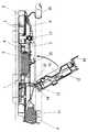
本実施形態の照明器具1は引掛シーリング(図示せず)が設けられた施工面としての天井面Sに取り付けて使用されるものであって、図1に示すように、引掛シーリングに電気的および機械的に接続される引掛シーリングアダプタ2(図2参照)を有する器具本体3と、器具本体3の下方に保持される環状の主光源4と、透光性を有する材料から形成され器具本体3との間に主光源4が位置するように主光源4の下方を覆うカバー5とを備えている。さらに、主光源4よりも光出力の小さいLED(発光ダイオード)からなる副光源6が設けられている。以下では、天井面Sに照明器具1を取り付けた状態を示す図1の上下左右を上下左右として説明する。  Thelighting fixture 1 of this embodiment is used by being attached to a ceiling surface S as a construction surface provided with a hooking ceiling (not shown), and as shown in FIG. An instrumentmain body 3 having a hook sealing adapter 2 (see FIG. 2) mechanically connected, an annularmain light source 4 held below the instrumentmain body 3, and an instrumentmain body 3 formed of a translucent material. And acover 5 that covers the lower part of themain light source 4 so that themain light source 4 is positioned between the two. Further, asub light source 6 composed of an LED (light emitting diode) having a light output smaller than that of themain light source 4 is provided. Below, the upper and lower left and right of FIG. 1 which shows the state which attached thelighting fixture 1 to the ceiling surface S is demonstrated as upper and lower left and right.

本実施形態の器具本体3は円盤状に形成されており、前記引掛シーリングアダプタ2を引掛シーリングに接続することによって、上面を天井面Sに対向させた状態で天井面Sに取り付けられる。器具本体3の下面中央部には円形状に凹んだ凹所7が形成されており、引掛シーリングアダプタ2は、図2に示すように、凹所7の底面中央部に上下方向に貫設されたアダプタ孔8内に配置される。器具本体3の下面のうち凹所7の周囲においては、外周縁側ほど天井面Sに近づくように傾斜した傾斜面9が形成されている。そして、当該傾斜面9には主光源4を保持するランプ支持具10およびランプソケット11が下方に突出する形で設けられており、主光源4は傾斜面9から離れた位置に保持される。ここでは、主光源4の一例として2重環形の蛍光ランプを用いている。さらに、上記器具本体3に対しては、主光源4の内側となる位置に凹所7を塞ぐ構造のアダプタカバー12が取り付けられている。詳しくは後述するが、このアダプタカバー12内に前記副光源6が収納されている。  The instrumentmain body 3 of the present embodiment is formed in a disc shape, and is attached to the ceiling surface S with the upper surface facing the ceiling surface S by connecting thehook ceiling adapter 2 to the hook ceiling. Arecess 7 that is recessed in a circular shape is formed at the center of the lower surface of theinstrument body 3, and thehook sealing adapter 2 is vertically provided at the center of the bottom surface of therecess 7 as shown in FIG. 2. It is arranged in theadapter hole 8. Aninclined surface 9 is formed around therecess 7 in the lower surface of theinstrument body 3 so as to be closer to the ceiling surface S toward the outer peripheral edge side. Theinclined surface 9 is provided with alamp support 10 and alamp socket 11 for holding themain light source 4 so as to protrude downward, and themain light source 4 is held at a position away from theinclined surface 9. Here, a double-ring fluorescent lamp is used as an example of themain light source 4. Furthermore, anadapter cover 12 having a structure for closing therecess 7 is attached to theinstrument body 3 at a position inside themain light source 4. As will be described in detail later, theauxiliary light source 6 is accommodated in theadapter cover 12.

アダプタカバー12は凹所7と同等の直径の円盤状であって、左端部に前後方向(図1では紙面に直交する方向)に軸受け孔が貫通した軸受け部13が設けられている。この軸受け孔には、器具本体3における凹所7の周縁に支持される回動軸14が挿通される。これにより、アダプタカバー12は器具本体3に対して、図2に示すように回動軸14を中心として凹所7を塞ぐ位置と開放する位置との間で回動可能に軸支される。ここで、アダプタカバー12が凹所7を塞いだ状態では、アダプタカバー12の上端部が凹所7内に嵌り込む形になる。なお、引掛シーリングアダプタ2の下面側には器具本体3に電気的に接続された電源コネクタ15が接続されるので、アダプタカバー12の上面には当該電源コネクタ15が収納される凹部16を設けてある。  Theadapter cover 12 has a disk shape with a diameter equivalent to that of therecess 7, and a bearingportion 13 having a bearing hole penetrating in the front-rear direction (a direction perpendicular to the paper surface in FIG. 1) is provided at the left end portion. Arotation shaft 14 supported by the peripheral edge of therecess 7 in theinstrument body 3 is inserted through the bearing hole. Thereby, theadapter cover 12 is pivotally supported with respect to the instrumentmain body 3 so as to be rotatable between a position where therecess 7 is closed and a position where therecess 7 is opened with therotation shaft 14 as the center as shown in FIG. Here, in a state in which theadapter cover 12 closes therecess 7, the upper end portion of theadapter cover 12 is fitted into therecess 7. In addition, since thepower connector 15 electrically connected to theinstrument body 3 is connected to the lower surface side of the hookingceiling adapter 2, arecess 16 for accommodating thepower connector 15 is provided on the upper surface of theadapter cover 12. is there.

さらにアダプタカバー12には、右端部からアダプタカバー12の上面に沿って右方に突出し、長孔(図示せず)が形成された係合部18が設けられている。器具本体3において、アダプタカバー12が凹所7を塞いだ状態で係合部18に対応する位置には、係合部18の長孔に挿入されるラッチ部17が設けられている。ラッチ部17は、長孔に挿入された状態で水平面内で90度回転させることによって係合部18における長孔の周囲に引っ掛かる構造を有している。すなわち、係合部18をラッチ部17に係合させることによって、凹所7を塞ぐ位置にアダプタカバー12を保持することができる。ここで、天井面Sへの器具本体3の取り付け作業時には、引掛シーリングアダプタ2を引掛シーリングに結合するために、係合部18とラッチ部17との係合を解除して凹所7を開放し、天井面Sへの取り付けが完了すれば、凹所7を塞いで係合部18とラッチ部17とを係合させることにより、凹所7を塞ぐ位置にアダプタカバー12を固定する。  Further, theadapter cover 12 is provided with an engagingportion 18 that protrudes rightward from the right end portion along the upper surface of theadapter cover 12 and has a long hole (not shown). In theinstrument body 3, alatch portion 17 that is inserted into the long hole of theengagement portion 18 is provided at a position corresponding to theengagement portion 18 in a state where theadapter cover 12 closes therecess 7. Thelatch part 17 has a structure which is hooked around the long hole in the engagingpart 18 by rotating 90 degrees in a horizontal plane in a state of being inserted into the long hole. That is, by engaging the engagingportion 18 with thelatch portion 17, theadapter cover 12 can be held at a position where therecess 7 is closed. Here, when thefixture body 3 is attached to the ceiling surface S, the engagement between theengagement portion 18 and thelatch portion 17 is released to open therecess 7 in order to couple thehook ceiling adapter 2 to the hook ceiling. When the attachment to the ceiling surface S is completed, theadapter cover 12 is fixed at a position where therecess 7 is closed by closing therecess 7 and engaging the engagingportion 18 and thelatch portion 17.

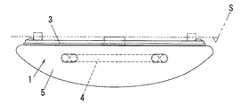
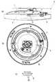
一方、カバー5は、図3に示すように直径がアダプタカバー12と同等の円形状の開口部19を有した環状に形成されており、図1のようにアダプタカバー12の下端部が開口部19に挿入された状態でアダプタカバー12に支持される。開口部19に挿入されるアダプタカバー12の下端縁には、周方向に延長された支持リブ20が複数箇所(ここでは4箇所)の切欠21を除いた全周に形成されている。そして、カバー5の開口部19周縁にはアダプタカバー12の各切欠21に対応する位置にそれぞれ開口部19内に突出する支持突起22が形成されている。これにより、切欠21と支持突起22との位置を合わせてアダプタカバー12の下端部をカバー5の開口部19に上方から挿入させた後、カバー5を周方向に回転させて切欠21と支持突起22との位置をずらせば、支持突起22が支持リブ20に引っ掛かってカバー5がアダプタカバー12に支持されることになる。さらにここでは、アダプタカバー12の外周面に、アダプタカバー12に対するカバー5の回転範囲を規制する規制リブ23も形成されている。なお、カバー5は、照明器具1の下方から主光源4が直接見えてしまうことがないように光拡散透過性を有する材料から形成されており、ここではカバー5の外径を器具本体3の外径よりも大きくすることにより、器具本体3が下方から直接見えることも防止している。  On the other hand, thecover 5 is formed in an annular shape having acircular opening 19 having the same diameter as theadapter cover 12 as shown in FIG. 3, and the lower end of theadapter cover 12 is the opening as shown in FIG. 19 is supported by theadapter cover 12 in a state of being inserted into theadapter 19. On the lower end edge of theadapter cover 12 inserted into theopening 19,support ribs 20 extending in the circumferential direction are formed on the entire circumference excluding a plurality of (here, four)notches 21. Further,support protrusions 22 protruding into theopening 19 are formed at positions corresponding to thenotches 21 of theadapter cover 12 at the periphery of theopening 19 of thecover 5. Thereby, after aligning the positions of thenotch 21 and thesupport protrusion 22 and inserting the lower end portion of theadapter cover 12 into theopening 19 of thecover 5 from above, thecover 5 is rotated in the circumferential direction to thereby cut thenotch 21 and the support protrusion. If the position with respect to 22 is shifted, thesupport protrusion 22 is caught by thesupport rib 20 and thecover 5 is supported by theadapter cover 12. Further, here, on the outer peripheral surface of theadapter cover 12, aregulation rib 23 for regulating the rotation range of thecover 5 relative to theadapter cover 12 is also formed. Thecover 5 is formed of a material having light diffusibility so that the mainlight source 4 is not directly visible from below thelighting fixture 1. By making it larger than the outer diameter, theinstrument body 3 is also prevented from being seen directly from below.

また、本実施形態では、図4に示すようにアダプタカバー12が、上下方向に分割可能なボディ24と内カバー25とを有し、ボディ24と内カバー25との間に副光源6を収納した構成を採用している。そのため、ここではボディ24と内カバー25とのそれぞれが透光性を有する材料から形成されている。ただし、ボディ24および内カバー25は、透明でもよいし、副光源6の光を拡散透過させる拡散性を有してもよい。アダプタカバー12が凹所7を塞いだ状態ではボディ24が下側、内カバー25が上側となる。内カバー25におけるボディ24との対向面には、断面コ字状の保持突起26が2個1組として突設されており、対をなす2個の保持突起26は互いの対向面に溝27を有する向きに形成される。  In the present embodiment, as shown in FIG. 4, theadapter cover 12 has abody 24 and aninner cover 25 that can be divided in the vertical direction, and the auxiliarylight source 6 is accommodated between thebody 24 and theinner cover 25. The configuration is adopted. Therefore, here, each of thebody 24 and theinner cover 25 is formed of a material having translucency. However, thebody 24 and theinner cover 25 may be transparent, or may have a diffusibility that diffuses and transmits the light from thesub-light source 6. When theadapter cover 12 closes therecess 7, thebody 24 is on the lower side and theinner cover 25 is on the upper side. Two holdingprojections 26 having a U-shaped cross section are provided as a pair on the surface of theinner cover 25 that faces thebody 24, and the two holdingprojections 26 that make a pair havegrooves 27 on the opposing surfaces. It is formed in the direction which has.

副光源6は、複数個のLED28を実装基板29の一面上に並べて構成されており、各組の保持突起26に対して、実装基板29の左右各端部が各保持突起26の溝27に挿入されるように取り付けられることによって内カバー25に保持される。各LED28はそれぞれ、先端面が球面状に形成された砲弾型のレンズを有し、レンズの先端面を光の取り出し面としている。つまりレンズの中心軸方向を光の取り出し方向として光が取り出されることになる。ここでは、内カバー25には2組の保持突起26を設け、それぞれ各組の保持突起26間に保持される2組の副光源6を設けてある。各組の副光源6は、それぞれのLED28の光の取り出し方向が水平方向となる向きに向けられている。ここで、副光源6は、器具本体3の凹所7の内周面によって光が遮られることのないように、アダプタカバー12によって凹所7を塞いだ状態で凹所7の下端縁よりも下方となる位置に配置される。  Thesub-light source 6 is configured by arranging a plurality ofLEDs 28 on one surface of the mountingboard 29, and the left and right ends of the mountingboard 29 correspond to thegrooves 27 of the holdingprotrusions 26 with respect to the holdingprotrusions 26 of each set. It is held by theinner cover 25 by being attached so as to be inserted. EachLED 28 has a bullet-shaped lens having a tip surface formed in a spherical shape, and the tip surface of the lens is used as a light extraction surface. That is, light is extracted with the central axis direction of the lens as the light extraction direction. Here, two sets of holdingprojections 26 are provided on theinner cover 25, and two sets of auxiliarylight sources 6 held between the holdingprojections 26 of each set are provided. Each set ofsub-light sources 6 is oriented in a direction in which the light extraction direction of eachLED 28 is horizontal. Here, the auxiliarylight source 6 has a lower end than the lower end edge of therecess 7 in a state where therecess 7 is closed by theadapter cover 12 so that light is not blocked by the inner peripheral surface of therecess 7 of theinstrument body 3. It arrange | positions in the position used as the downward direction.

なお、ここで用いるアダプターカバー12にはさらに、照明器具1のオンオフ制御や調光制御等を行う赤外線リモコン用のリモコン受光部30が収納される。アダプタカバー12のボディ24には、リモコン受光部30の下面を露出させるように貫設された窓孔31が形成されている。器具本体3の内部回路(図示せず)と、アダプタカバー12内に設けた副光源6およびリモコン受光部30とを電気的に接続する接続線32は、アダプタカバー12の開閉の邪魔にならないように回動軸14の近傍を通して引き回される。  Note that theadapter cover 12 used here further houses a remote controllight receiving unit 30 for an infrared remote control that performs on / off control, dimming control, and the like of thelighting fixture 1. Awindow hole 31 is formed in thebody 24 of theadapter cover 12 so as to penetrate the lower surface of the remote controllight receiving unit 30. Aconnection line 32 that electrically connects an internal circuit (not shown) of theinstrument body 3 to the auxiliarylight source 6 and the remote controllight receiving unit 30 provided in theadapter cover 12 does not interfere with the opening and closing of theadapter cover 12. Is routed through the vicinity of thepivot shaft 14.

ところで、本実施形態の照明器具1においては、以下の構成によって副光源6からの直接光を天井面Sに照射できるようにしてある。  By the way, in thelighting fixture 1 of this embodiment, the direct light from thesublight source 6 can be irradiated to the ceiling surface S by the following structures.

すなわち、カバー5は、図1に示すように、副光源6からの直接光を天井面Sに照射する間隙33を、器具本体3との間に有する形状に形成されている。この構成により、副光源6からの光は図1に矢印Aで示すように前記間隙33を通して天井面Sに直接照射することができる。間隙33はカバー5の上面と器具本体3の下面との間に形成されることになるが、器具本体3の下面には上述したように外周縁側ほど天井面Sに近づくように傾斜した傾斜面9が形成されているので、副光源6から天井面Sに向かう斜め上向きの光を器具本体3に遮られることなく取り出すことができる。さらにまた、主光源4は上述したように器具本体3の傾斜面9から離れて保持されているので、副光源6から天井面Sに向かう光は、主光源4と傾斜面9との間を通ることになり、主光源4によって遮られることもない。  That is, as shown in FIG. 1, thecover 5 is formed in a shape having agap 33 for irradiating the ceiling surface S with direct light from thesub-light source 6 between thecover 5 and theinstrument body 3. With this configuration, the light from thesub-light source 6 can be directly applied to the ceiling surface S through thegap 33 as indicated by an arrow A in FIG. Thegap 33 is formed between the upper surface of thecover 5 and the lower surface of the instrumentmain body 3, but the lower surface of the instrumentmain body 3 is inclined so as to be closer to the ceiling surface S toward the outer peripheral edge as described above. 9 is formed, the obliquely upward light directed from the auxiliarylight source 6 toward the ceiling surface S can be taken out without being blocked by theinstrument body 3. Furthermore, since the mainlight source 4 is held away from theinclined surface 9 of theinstrument body 3 as described above, the light traveling from thesub light source 6 toward the ceiling surface S passes between the mainlight source 4 and theinclined surface 9. It will pass and will not be blocked by the mainlight source 4.

ここにおいて、上述したように副光源6をLED28の光の取り出し方向が水平方向となる向きに向けているので、副光源6の光は天井面Sに沿って照明器具1から比較的離れたところに主として向けられることになる。要するに副光源6からの光を照明器具1から比較的離れたところにまで届かせることができる。ここではさらに、副光源6から天井面Sに向かって出射する光をカバー5が遮ることがないように、カバー5の外周縁が副光源6よりも下方に位置するようにカバー5の形状が設計されている。  Here, as described above, since the auxiliarylight source 6 is directed in the direction in which the light extraction direction of theLED 28 is horizontal, the light of the auxiliarylight source 6 is relatively far from thelighting fixture 1 along the ceiling surface S. Will be mainly directed to. In short, the light from the auxiliarylight source 6 can reach a relatively distant place from thelighting fixture 1. Further, the shape of thecover 5 is such that the outer peripheral edge of thecover 5 is positioned below thesub light source 6 so that thecover 5 does not block the light emitted from thesub light source 6 toward the ceiling surface S. Designed.

しかも、副光源6は、器具本体3の下側であって主光源4の内側となる位置に配置されているので、従来構成のように副光源6を配置するために器具本体3の外径をカバー5よりも大きく形成する必要はなくなり、従来構成に比べて器具本体3を小型化することができる。ここでは器具本体3の外径をカバー5よりも小さく、かつ主光源4よりも小さく設定している。  Moreover, since the auxiliarylight source 6 is disposed at a position below the instrumentmain body 3 and inside the mainlight source 4, the outer diameter of the instrumentmain body 3 is used to arrange the auxiliarylight source 6 as in the conventional configuration. Need not be formed larger than thecover 5, and theinstrument body 3 can be downsized compared to the conventional configuration. Here, the outer diameter of theinstrument body 3 is set smaller than thecover 5 and smaller than the mainlight source 4.

また本実施形態では、主光源4とカバー5とが、天井面Sからのカバー5の高さ寸法が主光源4の高さの範囲内に収まるように、つまり上下方向においてカバー5の外周縁が主光源4の上下両端間に位置するように位置関係が設定されている。主光源4とカバー5とを上記位置関係としたことにより、主光源4からの光がカバーを通さずに直接下方に照射することはなく、照明器具1の下方から主光源4が直接見えることもない。しかも、主光源4から天井面Sに向かう光はカバー5に遮られることがないので、主光源4からの直接光においても、図1に矢印Bで示すように前記間隙33を通して天井面Sに照射することになる。  Further, in the present embodiment, the mainlight source 4 and thecover 5 are arranged so that the height dimension of thecover 5 from the ceiling surface S is within the height range of the mainlight source 4, that is, the outer peripheral edge of thecover 5 in the vertical direction. Is set so that is positioned between the upper and lower ends of the mainlight source 4. Since the mainlight source 4 and thecover 5 are in the above positional relationship, the light from the mainlight source 4 does not irradiate directly downward without passing through the cover, and the mainlight source 4 can be directly seen from below thelighting fixture 1. Nor. In addition, since the light traveling from the mainlight source 4 toward the ceiling surface S is not blocked by thecover 5, even direct light from the mainlight source 4 is directed to the ceiling surface S through thegap 33 as shown by an arrow B in FIG. Will be irradiated.

ただし、主光源4の光は主光源4から放射状に出射されるので、主光源4を点灯させた際には天井面Sにおいて主光源4の近傍、つまり照明器具1の近傍の照度が特に高くなる。これに対して、副光源6の光は上述したように天井面Sにおいて照明器具1から比較的離れたところに主に向けられているので、副光源6を点灯させた際には天井面Sにおいて照明器具1から離れたところの照度が特に高くなる。要するに主光源4と副光源6とでは、天井面Sにおいて主に光を照射する範囲が相違し、照明器具1の周囲の天井面Sを違った形に照らすことができるので、互いに異なる雰囲気を演出することができる。  However, since the light from the mainlight source 4 is emitted radially from the mainlight source 4, when the mainlight source 4 is turned on, the illuminance in the vicinity of the mainlight source 4 on the ceiling surface S, that is, in the vicinity of theluminaire 1 is particularly high. Become. On the other hand, since the light from thesub-light source 6 is mainly directed to the ceiling surface S at a position relatively distant from thelighting fixture 1 as described above, the ceiling surface S is turned on when thesub-light source 6 is turned on. In particular, the illuminance away from theluminaire 1 is particularly high. In short, the mainlight source 4 and thesub-light source 6 are different in the range in which light is mainly irradiated on the ceiling surface S, and can illuminate the ceiling surface S around thelighting fixture 1 in different shapes, so that different atmospheres are provided. Can produce.

図1では2組の副光源6におけるそれぞれの光の取り出し面(つまりLED28の先端面)を左方および右方に向けているが、この構成に限るものではない。つまり、たとえばランプ支持具10やランプソケット11、回動軸14や接続線32等が副光源6からの光を遮る位置に存在するのであれば、図4に示すように各組の副光源6におけるそれぞれの光の取り出し面を前方および後方に向けるなどして、水平方向であってランプ支持具10やランプソケット11、回動軸14や接続線32等が存在しない方向に副光源6の光が出射される構成とすることが望ましい。  In FIG. 1, the light extraction surfaces (that is, the front end surfaces of the LEDs 28) of the two sets ofsub-light sources 6 are directed leftward and rightward, but the present invention is not limited to this configuration. That is, for example, if thelamp support 10, thelamp socket 11, therotation shaft 14, theconnection line 32, etc. are present at positions where they block the light from thesub-light source 6, as shown in FIG. The light extraction surfaces of thesub light sources 6 are directed forward and rearward, for example, so that the light from the auxiliarylight source 6 is in a horizontal direction in which thelamp support 10, thelamp socket 11, the rotatingshaft 14, theconnection line 32, etc. do not exist. It is desirable to adopt a configuration that emits light.

また、本実施形態の照明器具1は、副光源6からの光を天井面Sに照射するだけではなく天井面Sとは反対側つまり照明器具1の下方にも出射する。そのための構成として、図5に示すように、透光性を有する材料から形成され器具本体3との間に副光源6が位置するように副光源6の下方を覆うキャップ34が設けられている。キャップ34はカバー5と同様にアダプカバー12に支持されるものであって、アダプタカバー12の下面にはキャップ34を取り付けるための取付孔35が外周縁に沿って複数個(ここでは2個)形成されている。各取付孔35は、アダプタカバー12の周方向に延長されており、長手方向の一端部のみが幅広に形成されている。キャップ34には、各取付孔35に対応する位置に、それぞれ上方に突出し、先端部が内側に延長されたL字状の取付片36が設けられている。これにより、取付片36の先端部を取付孔35の幅広の一端部からアダプタカバー12内に挿入し、キャップ34を周方向に回転させれば、取付片36の先端部が取付孔35の周囲に引っ掛かってキャップ34がアダプタカバー12に支持されることになる。  Moreover, thelighting fixture 1 of this embodiment not only irradiates the ceiling surface S with the light from thesub-light source 6 but also emits it on the opposite side of the ceiling surface S, that is, below thelighting fixture 1. As a configuration for that purpose, as shown in FIG. 5, acap 34 that is formed of a light-transmitting material and covers the lower side of the auxiliarylight source 6 is provided so that the auxiliarylight source 6 is positioned between theinstrument body 3. . Thecap 34 is supported by theadapter cover 12 in the same manner as thecover 5, and a plurality of mounting holes 35 (two in this case) are provided on the lower surface of theadapter cover 12 along the outer peripheral edge. Is formed. Eachattachment hole 35 is extended in the circumferential direction of theadapter cover 12, and only one end portion in the longitudinal direction is formed wide. Thecap 34 is provided with an L-shapedattachment piece 36 that protrudes upward at a position corresponding to eachattachment hole 35 and has a tip portion extended inward. As a result, the tip of theattachment piece 36 is inserted into theadapter cover 12 from the wide end of theattachment hole 35 and thecap 34 is rotated in the circumferential direction. As a result, thecap 34 is supported by theadapter cover 12.

副光源6を収納したアダプタカバー12において副光源6の下方を覆っているボディ24は上述したように透光性を有する材料から形成されているので、上記構成により、副光源6からの光はアダプタカバー12とキャップ34とを通して下方に出射されることになる。ただし、キャップ34は、照明器具1の下方から副光源6やリモコン受光部30が直接見えてしまうことがないように、光拡散透過性を有する材料から形成することが望ましい。  Since thebody 24 covering the lower side of the auxiliarylight source 6 in theadapter cover 12 containing the auxiliarylight source 6 is formed of a light-transmitting material as described above, the light from the auxiliarylight source 6 can be obtained by the above configuration. The light is emitted downward through theadapter cover 12 and thecap 34. However, thecap 34 is desirably formed of a material having light diffusive transparency so that the auxiliarylight source 6 and the remote controllight receiving unit 30 are not directly seen from below thelighting fixture 1.

さらに、カバー5において主光源4の内側であって副光源6を囲む部位には、上下方向に貫通する出射窓37が形成されており、この出射窓37を通しても副光源6の光の一部(図1に矢印Cで示す)は下方に取り出されることになる。本実施形態では出射窓37はアダプタカバー12の周方向に4分割されている。またカバー5は、出射窓37の内周面に副光源6からの光の一部を反射する反射面38を形成している。反射面38は上方ほど出射窓37の開口面積が小さくなるように傾斜しており、反射面38に照射する副光源6からの光の一部を反射面38で下方に反射する。これにより、副光源6の光を出射窓37から下方に効率よく取り出すことができる。  Further, anemission window 37 penetrating in the vertical direction is formed in a portion of thecover 5 inside the mainlight source 4 and surrounding the auxiliarylight source 6. A part of the light of the auxiliarylight source 6 is also passed through theemission window 37. (Indicated by arrow C in FIG. 1) will be taken down. In the present embodiment, theexit window 37 is divided into four in the circumferential direction of theadapter cover 12. Further, thecover 5 has areflection surface 38 that reflects a part of the light from thesub-light source 6 on the inner peripheral surface of theemission window 37. Thereflection surface 38 is inclined so that the opening area of theemission window 37 becomes smaller toward the upper side, and a part of the light from thesub-light source 6 that irradiates thereflection surface 38 is reflected downward by thereflection surface 38. Thereby, the light of the auxiliarylight source 6 can be efficiently extracted downward from theemission window 37.

なお、副光源6は、主光源4の消灯時に点灯させる常夜灯として機能するものであってもよいが、主光源4と同時に点灯させることにより照明器具1の出力光の演色性を高めるために用いてもよい。また、副光源6として用いるLED28の発光色は特に限定するものではなく、電球色や青色などの発光色を適宜選択すればよい。  Thesub-light source 6 may function as a night light that is turned on when the mainlight source 4 is turned off. May be. Moreover, the light emission color of LED28 used as thesublight source 6 is not specifically limited, What is necessary is just to select light emission colors, such as a light bulb color and blue, suitably.

上記実施形態では、天井面Sに取り付けられる照明器具1を例示したが、本発明の照明器具1が取り付けられる施工面は天井面Sに限るものではなく、たとえば壁面などであってもよい。  In the said embodiment, although thelighting fixture 1 attached to the ceiling surface S was illustrated, the construction surface where thelighting fixture 1 of this invention is attached is not restricted to the ceiling surface S, For example, a wall surface etc. may be sufficient.

本発明の実施形態を示し、一部を破断した正面図である。It is the front view which showed embodiment of this invention and fractured | ruptured one part.同上に用いる器具本体およびアダプタカバーを示す断面図である。It is sectional drawing which shows the instrument main body and adapter cover used for the same as the above.同上の分解斜視図である。It is an exploded perspective view same as the above.同上に用いるアダプタカバーの分解斜視図である。It is a disassembled perspective view of the adapter cover used for the same as the above.同上の分解斜視図である。It is an exploded perspective view same as the above.従来例を示す正面図である。It is a front view which shows a prior art example.他の従来例を示し、(a)は一部を破断した正面図、(b)は器具本体の下面図、(c)は要部の正面図である。Another example is shown, (a) is a front view with a part broken away, (b) is a bottom view of the instrument body, and (c) is a front view of the main part.さらに他の従来例を示し、(a)は一部を破断した正面図、(b)は(a)の要部の下面図、(c)は一部を破断した正面図、(d)は(c)の要部の下面図である。Still another conventional example is shown, (a) is a front view with a part broken away, (b) is a bottom view of the main part of (a), (c) is a front view with a part broken, (d) It is a bottom view of the principal part of (c).さらに他の従来例を示す斜視図である。It is a perspective view which shows another prior art example.

符号の説明Explanation of symbols

1 照明器具
3 器具本体
4 主光源
5 カバー
6 副光源
28 LED
33 間隙
34 キャップ
37 出射窓
38 反射面
S 天井面(施工面)

DESCRIPTION OFSYMBOLS 1Lighting fixture 3 Appliancemain body 4 Mainlight source 5Cover 6 Sublight source 28 LED
33Gap 34Cap 37Exit window 38 Reflecting surface S Ceiling surface (Construction surface)

Claims (7)

Translated fromJapanese
施工面に取り付けられる器具本体と、器具本体に保持される環状の主光源と、施工面との間に器具本体を配置するように主光源の内側に器具本体により保持されるLEDからなる副光源と、施工面から離れて配置され施工面との間に主光源を配置するように主光源を覆うカバーとを備え、カバーは、副光源からの直接光を施工面に照射する間隙を器具本体との間に有する形状に形成され、器具本体のうち副光源の周囲には、外周縁側ほど施工面に近づくように傾斜した傾斜面が形成されており、器具本体は、副光源から施工面に向かう光が主光源と前記傾斜面との間を通るように、主光源を前記傾斜面から離して保持していることを特徴とする照明器具。Sub-light source comprising an instrument main body attached to the construction surface, an annular main light source held by the instrument main body, and an LED held by the instrument main body inside the main light source so as to place the instrument main body between the construction surface And a cover covering the main light source so as to dispose the main light source between the work surface and the work surface, and the cover has a gap for irradiating the work surface with direct light from the sub-light source.An inclined surface that is inclined so as to approach the construction surface toward the outer peripheral edge side is formed around the auxiliary light source in the instrument body, and the instrument body is moved from the auxiliary light source to the construction surface. The illuminating device, wherein the main light source is held away from the inclined surface so that the light traveling there passes between the main light source and the inclined surface . 前記カバーは、前記間隙を通して前記主光源からの直接光を前記施工面に照射する形状に形成されていることを特徴とする請求項1記載の照明器具。  The lighting device according to claim 1, wherein the cover is formed in a shape that irradiates the construction surface with direct light from the main light source through the gap. 前記副光源は、光の放射方向に指向性を有し、光を強く放射する方向を前記間隙に向けて配置されていることを特徴とする請求項1または請求項2に記載の照明器具。  The lighting apparatus according to claim 1, wherein the sub-light source has directivity in a light emission direction and is arranged with a direction in which light is strongly emitted toward the gap. 透光性を有し前記器具本体との間に前記副光源を配置するように副光源を覆うキャップを備えることを特徴とする請求項1ないし請求項3のいずれか1項に記載の照明器具。  The lighting fixture according to any one of claims 1 to 3, further comprising a cap that has translucency and covers the auxiliary light source so as to dispose the auxiliary light source between the fixture main body. . 前記施工面に直交する方向において前記主光源の幅寸法の範囲内に前記カバーの外周縁が位置することを特徴とする請求項1ないし請求項4のいずれか1項に記載の照明器具。  5. The lighting apparatus according to claim 1, wherein an outer peripheral edge of the cover is positioned within a range of a width dimension of the main light source in a direction orthogonal to the construction surface. 前記カバーは、前記主光源の内側であって前記副光源を囲む部位に、前記施工面に交わる向きに貫通した出射窓を有することを特徴とする請求項1ないし請求項5のいずれか1項に記載の照明器具。  6. The cover according to claim 1, wherein the cover has an exit window penetrating in a direction intersecting the construction surface at a portion inside the main light source and surrounding the sub light source. The lighting fixture as described in. 前記カバーは、前記出射窓の内周面に、前記副光源の光を出射窓から出射させるように反射する反射面が形成されていることを特徴とする請求項6記載の照明器具。

The lighting device according to claim 6, wherein the cover has a reflection surface formed on an inner peripheral surface of the emission window for reflecting the light from the sub-light source to be emitted from the emission window.

JP2006047410A2006-02-232006-02-23 lighting equipmentExpired - Fee RelatedJP4634944B2 (en)

Priority Applications (1)

Application NumberPriority DateFiling DateTitle
JP2006047410AJP4634944B2 (en)2006-02-232006-02-23 lighting equipment

Applications Claiming Priority (1)

Application NumberPriority DateFiling DateTitle
JP2006047410AJP4634944B2 (en)2006-02-232006-02-23 lighting equipment

Publications (2)

Publication NumberPublication Date
JP2007227177A JP2007227177A (en)2007-09-06
JP4634944B2true JP4634944B2 (en)2011-02-16

Family

ID=38548794

Family Applications (1)

Application NumberTitlePriority DateFiling Date
JP2006047410AExpired - Fee RelatedJP4634944B2 (en)2006-02-232006-02-23 lighting equipment

Country Status (1)

CountryLink
JP (1)JP4634944B2 (en)

Families Citing this family (4)

* Cited by examiner, † Cited by third party
Publication numberPriority datePublication dateAssigneeTitle
JP4882945B2 (en)*2007-09-272012-02-22パナソニック電工株式会社 lighting equipment
JP4877179B2 (en)*2007-09-272012-02-15パナソニック電工株式会社 lighting equipment
JP4877180B2 (en)*2007-09-272012-02-15パナソニック電工株式会社 lighting equipment
JP4991013B1 (en)*2011-02-282012-08-01シャープ株式会社 lighting equipment

Family Cites Families (10)

* Cited by examiner, † Cited by third party
Publication numberPriority datePublication dateAssigneeTitle
JPS4730787U (en)*1971-04-261972-12-07
JPS55118404U (en)*1979-02-161980-08-21
JP2726787B2 (en)*1992-10-141998-03-11株式会社テック lighting equipment
JPH06168605A (en)*1992-11-271994-06-14Hitachi Lighting LtdIndirect lighting device
JP2000173310A (en)*1998-11-302000-06-23Toshiba Lighting & Technology Corp lighting equipment
JP2000228104A (en)*1999-02-082000-08-15Masamichi ShigaIlluminating method provided with night light
JP2000260205A (en)*1999-03-042000-09-22Matsushita Electric Works Ltd lighting equipment
JP4461605B2 (en)*2000-10-312010-05-12パナソニック電工株式会社 lighting equipment
JP4244660B2 (en)*2003-02-282009-03-25パナソニック電工株式会社 Ceiling mounted lighting fixture
JP2005183035A (en)*2003-12-162005-07-07Nec Lighting Ltd lighting equipment

Also Published As

Publication numberPublication date
JP2007227177A (en)2007-09-06

Similar Documents

PublicationPublication DateTitle
JP4894688B2 (en) Lighting device
JP4655952B2 (en) lighting equipment
JP5650962B2 (en) Surgical light
JP4657248B2 (en) lighting equipment
JP5450008B2 (en) lighting equipment
JP5416254B2 (en) Light source device
JP3164202U (en) LED bulb
JP4634944B2 (en) lighting equipment
JP5719127B2 (en) Indoor lighting fixture with LED light source
JP2009009870A (en) Light source unit and light bulb shaped lamp
JP6542579B2 (en) LED lighting device
JP6315373B2 (en) Light source unit and lighting apparatus
JP4631738B2 (en) lighting equipment
JP2014235956A (en)Lighting lamp body, lighting lamp, and lighting device
JP3184561U (en) Light emitting diode lamp
JP2014116206A (en)Illumination device
KR101176509B1 (en)Automotive LED lights indirect lighting
JP4500700B2 (en) lighting equipment
EP2390553A2 (en)LED illuminating apparatus
US20160061394A1 (en)Stand-type led lighting device
JP4938916B1 (en) Light source device
JP6689811B2 (en) lighting equipment
JP5357084B2 (en) LED lamp and lighting device
JP2010143346A (en)Indoor lighting device
JP6429672B2 (en) Light emitting device and lighting apparatus using the same

Legal Events

DateCodeTitleDescription
A621Written request for application examination

Free format text:JAPANESE INTERMEDIATE CODE: A621

Effective date:20081208

RD04Notification of resignation of power of attorney

Free format text:JAPANESE INTERMEDIATE CODE: A7424

Effective date:20100730

A977Report on retrieval

Free format text:JAPANESE INTERMEDIATE CODE: A971007

Effective date:20100809

A131Notification of reasons for refusal

Free format text:JAPANESE INTERMEDIATE CODE: A131

Effective date:20100824

A521Request for written amendment filed

Free format text:JAPANESE INTERMEDIATE CODE: A523

Effective date:20101025

TRDDDecision of grant or rejection written
A01Written decision to grant a patent or to grant a registration (utility model)

Free format text:JAPANESE INTERMEDIATE CODE: A01

Effective date:20101116

A01Written decision to grant a patent or to grant a registration (utility model)

Free format text:JAPANESE INTERMEDIATE CODE: A01

A61First payment of annual fees (during grant procedure)

Free format text:JAPANESE INTERMEDIATE CODE: A61

Effective date:20101119

R150Certificate of patent or registration of utility model

Free format text:JAPANESE INTERMEDIATE CODE: R150

FPAYRenewal fee payment (event date is renewal date of database)

Free format text:PAYMENT UNTIL: 20131126

Year of fee payment:3

R250Receipt of annual fees

Free format text:JAPANESE INTERMEDIATE CODE: R250

R250Receipt of annual fees

Free format text:JAPANESE INTERMEDIATE CODE: R250

R250Receipt of annual fees

Free format text:JAPANESE INTERMEDIATE CODE: R250

LAPSCancellation because of no payment of annual fees

[8]ページ先頭

©2009-2025 Movatter.jp