JP4634663B2 - Optical sensor mounting device - Google Patents
Optical sensor mounting deviceDownload PDFInfo
- Publication number
- JP4634663B2 JP4634663B2JP2001220446AJP2001220446AJP4634663B2JP 4634663 B2JP4634663 B2JP 4634663B2JP 2001220446 AJP2001220446 AJP 2001220446AJP 2001220446 AJP2001220446 AJP 2001220446AJP 4634663 B2JP4634663 B2JP 4634663B2
- Authority
- JP
- Japan
- Prior art keywords
- support
- holder
- base
- optical sensor
- column
- Prior art date
- Legal status (The legal status is an assumption and is not a legal conclusion. Google has not performed a legal analysis and makes no representation as to the accuracy of the status listed.)
- Expired - Lifetime
Links
Images


Landscapes
- Switches Operated By Changes In Physical Conditions (AREA)
- Geophysics And Detection Of Objects (AREA)
- Presses And Accessory Devices Thereof (AREA)
Description
Translated fromJapanese【0001】
【産業上の利用分野】
この発明は、多光軸光電センサのような光センサを取り付けるのに用いられる光センサ取付装置に関し、特に、この発明は、光センサの光軸を調整する機能を持つ光センサ取付装置に関する。
【0002】
【従来の技術】
典型的な多光軸光電センサは、図7に示すように、複数個の投光素子33が一列に配置された投光器31と、投光素子33と同数個の受光素子34が一列に配置された受光器32とから成る。投光器31と受光器32とは、各投光素子33と各受光素子34とが一対一に向き合うようにして、適当な距離だけ隔てて設置される。対をなす投光素子33と受光素子34とを結ぶ光軸35は互いに平行し、物体の有無を検知するための2次元の物体検知エリアSを形成している。
【0003】
この種の多光軸光電センサは、物体の有無を物体検知エリアSで広く検知し得るので、例えば、プレス機械の安全装置などに利用されている。プレス機械の危険領域内に人体が侵入したとき、いずれかの光軸35が人体により遮られて遮光状態となる。この遮光状態となった光軸35が1以上存在する場合に物体検知信号をプレス機械の制御装置へ出力し、プレス機械の動作を緊急停止させる。
【0004】
多光軸光電センサの投光器31や受光器32を床面上に設置するのに、従来、図8および図9に示すような構成の光センサ取付装置30が用いられている。
この光センサ取付装置30は、床面40上にアンカーボルト38により固定されるベース板35と、下端面に取付板37が溶接により固着された支柱36とから成る。前記ベース板35上に取付板37を支持し、取付板37とベース板35とを複数箇所でボルト39により締め付け固定して、支柱36を床面上に縦設する。
【0005】
前記取付板37の外周部には、図10(1)に示すように、90度等角の各位置に、それぞれねじ孔41が上下方向に貫通して形成されている。各ねじ孔41には光軸調整用のねじ軸42が上方よりねじ込まれる。各ねじ軸42は取付板37の裏面へ先端が突出し、ベース板35の上面に突き当たった後は、その突出長さ分だけ取付板37を押し上げる。各ねじ軸42の取付板37の裏面からの突出長さdを個々に調整することで、支柱36の床面40に対する傾き方向や傾き角度が変わるので、多光軸光電センサの光軸調整を自在に行い得る。なお、図中、43は前記ねじ軸42の突出状態を保持して突出長さdを固定するためのナットである。
【0006】
【発明が解決しようとする課題】
上記構成の光センサ取付装置の場合、4本の光軸調整用のねじ軸42により支柱36を傾動させて光軸を調整した後に、図10(2)に示すように、4本のボルト39を締め付けてベース板35に取付板37を固定するため、各ボルト39の締付力のばらつきに起因して支柱36が調整時の状態から変位し、光軸がずれるという問題がある。このため、光軸調整が容易でなく、光軸の微調整は困難である。
【0007】
この発明は、上記の問題点に着目してなされたもので、光センサ取付用の支柱の傾き調整と支持とを同じ支え軸をもって四方から行うことにより、光センサの光軸調整が容易であり、光軸の微調整も行うことができる光センサ取付装置を提供することを目的とする。
【0008】
【課題を解決するための手段】
この発明による光センサ取付装置は、床面上に固定することが可能なベースと、ベースに下端部が支持された状態で床面上に縦設される光センサ取付用の支柱とから成る。前記ベースは、支柱の下端部を少なくとも上下の二箇所で支持するための支持部を備えている。上方位置の支持部は、支柱の上下端が全周にわたって径方向へ変位することが可能な状態で支柱を支持する。下方位置の支持部は、支柱の外周面を少なくとも四方より中心に向けて進退調節が可能な支え軸の先端によって支持する。
【0009】
支柱の下端部は、ベースの上下二箇所で支持すれば足るが、三箇所以上で支持するようにしてもよい。例えば、三箇所で支持する場合は、最上位の位置の支持部は、支柱の上下端が全周にわたって径方向へ変位することが可能な状態で支柱を支持し、他の一箇所の支持部は、支柱の外周面を少なくとも四方より中心に向けて進退調節が可能な支え軸の先端によって支持し、残りの一箇所の支持部は、任意の方法で支柱を支持するようにする。なお、支え軸による支柱の支持は四方からで足るが、それ以上の方向から支持するようにしてもよい。
【0010】
上記した光センサ取付装置において、まず、ベースを床面上に固定し、次いで、ベースの上方位置の支持部により支柱の上下端が全周にわたって径方向へ変位することが可能な状態で支柱を支持する。その後、支え軸を個々に四方から進退動作させて光センサ取付用の支柱の傾きを調整しつつ支柱の外面を支持する。
この発明によると、光センサ取付用の支柱を支え軸により四方から支持するとともに、同じ支え軸により支柱の傾きを調整するようにしたので、光センサの光軸調整が容易であり、光軸の微調整も可能となる。
【0011】
前記ベースを床面上に固定するには種々の態様があるが、その一は、ベースに床面への取付基板を具備させ、その取付基板をアンカーボルトにより床面に固定するようにする。
【0012】
前記支柱には、種々の光センサを取り付けることができるが、好ましい実施態様においては、複数個の投光素子が整列して配置された多光軸光電センサの投光器や、前記投光素子と同数の受光素子が整列して配置された多光軸光電センサの受光器が取り付けられる。なお、前記投光器の投光素子には発光ダイオードが、受光器の受光素子にはフォトダイオードが、それぞれ用いられる。
【0013】
前記ベースは種々の形態があるが、好ましい一実施態様は、上面が開口した筒状体であり、この筒状体の上面の開口部に上方位置の支持部が設けられる。なお、筒状体は円筒状のものが望ましいが、角筒状のものであってもよい。
【0014】
この発明の好ましい一実施態様においては、前記上方位置の支持部は、支柱を通す貫通孔を有するホルダと、ホルダの貫通孔に対応させる貫通孔を有する弾性変形が可能なホルダ支持板とから成る。前記ホルダ支持板は、外周縁がベースに固定されかつ内周縁に前記ホルダが固定される。ホルダにはホルダの貫通孔に挿通された支柱が固定される。このような構成により、支柱は支柱の上下端が全周にわたって径方向へ変位することが可能な状態で支持される。
【0015】
前記ホルダ支持板には種々の実施態様があるが、好ましくは、板面に複数の溝が形成された板ばねを用いて構成される。この場合にホルダ支持板の全体を板ばねで構成してもよく、部分的に板ばねを用いて構成してもよい。
【0016】
この発明の好ましい他の実施態様においては、前記上方位置の支持部は、支柱を通す貫通孔を有する弾性変形が可能な筒状のホルダにより構成される。前記ホルダの上端はベースに固定され、ホルダの下端は前記貫通孔に挿通された支柱に直接的または間接的に固定される。このような構成によっても、支柱は支柱の上下端が全周にわたって径方向へ変位することが可能な状態で支持される。
【0017】
前記の「筒状のホルダ」は、全体がゴムのようは弾性材料で構成してもよく、金属または合成樹脂の筒状体に複数の溝を周設して弾性変形が可能な構造としてもよい。
また、ホルダの下端を支柱に間接的に固定するとは、別部材を介在させてホルダの下端を支柱に固定する、という意味である。
【0018】
この発明の好ましい一実施態様においては、前記下方位置の支持部は、ベースの90度等角の各位置にベースの中心に向けて形成されたねじ孔と、各ねじ孔にねじ込まれることにより先端がベース内に突出する4個の支え軸と、各支え軸のベース内への突出状態を保持するためのストッパとから成る。前記ストッパとして、例えばナットを用いることができる。
【0019】
【発明の実施の形態】
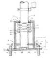
図1および図2は、この発明の一実施例である光センサ取付装置1の構成を示す。
図示例の光センサ取付装置1は、床面10上に固定することが可能なベース2と、ベース2に下端部が支持された状態で床面10上に縦設される光センサ取付用の支柱3とから成る。支柱3には、二個の取付金具4a,4bによって多光軸光電センサの投光器5が取り付けられている。前記投光器5は複数個の投光素子が整列して配置されたものである。
【0020】
なお、図示していないが、同じ構成の他の光センサ取付装置の支柱に多光軸光電センサの受光器が取り付けられる。その受光器は、前記投光器5の投光素子と同数の受光素子が整列して配置されたもので、対をなす投光素子と受光素子とが互いに向き合うように、投光器5が取り付けられた光センサ取付装置1と受光器が取り付けられた光センサ取付装置とが床面10上に設置される。
【0021】
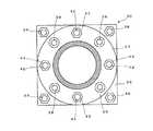
前記ベース2は、図3に示すように、上面が開口した円筒形状の筒状部11の下端面に、円盤状の取付基板12が溶接により一体に固着されて成る。前記取付基板12の外周部は筒状部11の外側面より張り出し、その張出部分の90度等角の位置にねじ孔13がそれぞれ形成されている。各ねじ孔13にはアンカーボルト14がねじ込まれ、取付基板12の下方へ突出したアンカーボルト14の軸部が床面10に埋設される。
【0022】
前記ベース2には、支柱3の下端部を上下の二箇所で支持するための支持部15,16が形成されている。上方位置の支持部15は筒状部11の上面の開口部に形成されている。下方位置の支持部16は筒状部11の下端部の取付基板12の近傍に形成されている。
【0023】
上方位置の支持部15は、支柱3の支持部分を支点として支柱3の上下端が首振り可能な状態、すなわち全周にわたって径方向へ変位することが可能な状態で支柱3を支持するもので、支柱3を通す貫通孔17aを有するリング形状のホルダ17と、ホルダ17の貫通孔17aと同径の貫通孔19aを有する弾性変形が可能なホルダ支持板19とから成る。
【0024】
前記ホルダ17には、90度等角の位置に、それぞれねじ孔23が径方向へ貫通して形成されている。各ねじ孔23にはねじ24がそれぞれねじ込まれ、ねじ24の先端がホルダ17の貫通孔17aへ突出する。ホルダ17の貫通孔17aには支柱3が挿通され、この支柱3の外周面に各ねじ24の先端が四方より当接して支柱3を固定する。
【0025】
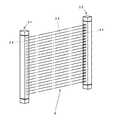
前記ホルダ支持板19は、全体が板ばねにより構成されており、しかも、弾性変形し易いように、板面の同心円に沿って複数個の円弧状の溝25が形成されている。前記ホルダ支持板19の外周縁はベース2の筒状部11の上端面に複数個のねじ21により一体に固定される。また、前記ホルダ17はホルダ支持板19の内周縁上に複数個のねじ22により一体に固定される。
前記支柱3は前記ホルダ17の貫通孔17aに挿通され、前記ねじ24により支柱3をホルダ17に固定したとき、支柱3は支柱3の上下端が首振り可能な状態、すなわち全周にわたって径方向へ変位することが可能な状態で支持される。
【0026】
なお、上記の実施例では、リング状のホルダ17と弾性変形が可能なホルダ支持板19とで上方位置の支持部15を構成しているが、これに限らず、図5および図6に示す実施例のように、弾性変形が可能な筒状のホルダ51を用いて前記支持部15を構成してもよい。各実施例におけるホルダ51の内孔は、支柱3の外径より大きな径に形成されている。図5に示す実施例のホルダ51は、金属製または合成樹脂製の筒状体に複数の溝53を周設して弾性変形が可能な構造に形成されている。また、図6に示す実施例のホルダ51は、ゴムのようは弾性材料を用いることにより弾性変形が可能な構成となっている。
【0027】
図5および図6の各実施例では、ベース2の筒状部11の上端には、支柱3を挿通することが可能な孔54を有する端板部11aが形成されており、この端板部11aに筒状のホルダ51の上端面が複数個のねじ55によって固定されている。ホルダ51の下端面にはリング形状の支持板57が複数個のねじ56によって固定されており、この支持板57が複数個のねじ58によって支柱3に固定されている。
【0028】
なお、図5の実施例では、ホルダ51と支持板57とをねじ56により固定しているが、ホルダ51に支持板57を一体形成することもできる。
また、図5の実施例では、ベース2の取付基板12の上面に凹曲面状の軸受穴59を形成し、一方、支柱3の下端面には凸曲面をなす合成樹脂製の摺動部材60を取り付け、支柱3が傾動し易いように前記摺動部材60を軸受穴59で摺動可能に支持するようにしているが、この軸受構造は、図5の実施例に限らず、図1および図6の各実施例にも採用できる。
【0029】
なお、図6の実施例においては、ゴム製のホルダ51とベース2の筒状部11との間、およびホルダ51と支持板57との間をねじ止めするために、ホルダ51の上端面および下端面には、ねじ55,56がねじ込まれるねじ孔61を備えた金属製のねじ管62がインサート成形されている。
【0030】
つぎに、前記下方位置の支持部16は、支柱3の外周面を四方より中心に向けて進退調節が可能な支え軸27の先端によって支持するように構成されている。すなわち、ベース2の筒状部11には90度等角の各位置に筒状部11の中心に向けてねじ孔26が貫通して形成されるとともに、各ねじ孔26に前記支え軸27が外側よりねじ込まれている。
【0031】
4本の支え軸27の先端が筒状部11の内孔20へ突出して支柱3の外周面に突き当たった状態のとき、支柱3の下端部が支持されて固定される。また、各支え軸27の筒状部11の内孔20への突出長さを調節すれば、支柱3の傾き方向および傾き角度が変わり、投光器5の光軸を変位させることができる。
各支え軸27の筒状部11の内孔20への突出状態は、ストッパとしてのナット28により保持される。ナット28が筒状部11の外周面に当たるまで支え軸27にねじ込まれたとき、支え軸27の内孔20への突出長さが固定される。
【0032】
上記した光センサ取付装置1により多光軸光電センサの投光器5を床面10に対して垂直に設置するには、まず、ベース2の取付基板12をアンカーボルト14によって床面10上に固定し、ベース2の筒状部11を床面10に対して垂直な姿勢に保持する。
【0033】
次いで、支持部15のホルダ17の貫通孔17aより支柱3をベース2の筒状部11内へ挿入した後、図4(1)に示すように、ホルダ17の各ねじ孔23へ六角レンチ29を用いてねじ24をねじ込み、支柱3をホルダ17に固定する。このとき、支柱3は、ホルダ支持板19が弾性変形してたわむことができるので、支柱3の上下端が全周にわたって径方向へ変位することが可能な状態で支持される。なお、図5および図6に示す実施例についても同様の要領にてねじ58により支持板57を支柱3に固定する。
【0034】
つぎに、図4(2)に示すように、支柱3の上端面に水準器6を設置した後、筒状部11の各ねじ孔26へ六角レンチ29を用いて支え軸27をそれぞれねじ込み、各支え軸27の先端を支柱3の外周面に突き当てる。各支え軸27を水準器6の気泡が中心に移動するように、個々に進退動作させることにより支柱3を鉛直状態に設定できるとともに、支柱3の外面を四方から支持できる。
【0035】
支柱3が鉛直状態になったとき、図4(3)に示すように、スパナ30を用いてナット28を締め付け、各支え軸27を固定する。この状態で支柱3に多光軸光電センサの投光器5を2個の取付金具4a,4bを用いて支柱3と平行に取り付けると、前記投光器5は鉛直状態となり、投光器5の光軸は水平となる。
【0036】
【発明の効果】
この発明によれば、支え軸の進退調節により支柱の傾き調整と支持とを可能としたから、光センサの光軸調整が容易となり、光軸の微調整も可能である。
【図面の簡単な説明】
【図1】この発明の一実施例である光センサ取付装置の縦断面図である。
【図2】図1の光センサ取付装置の平面図である。
【図3】図1の光センサ取付装置の分解斜視図である。
【図4】光センサ取付装置の設置手順を示す斜視図である。
【図5】他の実施例である光センサ取付装置の縦断面図である。
【図6】他の実施例である光センサ取付装置の縦断面図である。
【図7】多光軸光電センサの構成を示す斜視図である。
【図8】従来の光センサ取付装置の構成を示す正面図である。
【図9】図8のA−A線に沿う断面図である。
【図10】従来の光センサ取付装置における光軸調整の手順を示す断面図である。
【符号の説明】
1 光センサ取付装置
2 ベース
3 支柱
4 受光素子
5 投光器
12 取付基板
15,16 支持部
17 ホルダ
17a 貫通孔
19 ホルダ支持板
19a 貫通孔
25 溝
26 ねじ孔
27 支え軸
28 ナット[0001]
[Industrial application fields]
The present invention relates to an optical sensor mounting apparatus used for mounting an optical sensor such as a multi-optical axis photoelectric sensor, and in particular, the present invention relates to an optical sensor mounting apparatus having a function of adjusting the optical axis of the optical sensor.
[0002]
[Prior art]
As shown in FIG. 7, a typical multi-optical axis photoelectric sensor includes a
[0003]
Since this type of multi-optical axis photoelectric sensor can widely detect the presence or absence of an object in the object detection area S, it is used, for example, as a safety device for a press machine. When a human body enters the danger area of the press machine, any one of the
[0004]
In order to install the
This optical
[0005]
As shown in FIG. 10A,
[0006]
[Problems to be solved by the invention]
In the case of the optical sensor mounting device having the above-described configuration, after adjusting the optical axis by tilting the
[0007]
The present invention has been made paying attention to the above-mentioned problems. By adjusting the tilt of the support for mounting the optical sensor and supporting it from four sides with the same support shaft, the optical axis of the optical sensor can be easily adjusted. An object of the present invention is to provide an optical sensor mounting device that can also finely adjust the optical axis.
[0008]
[Means for Solving the Problems]
An optical sensor mounting device according to the present invention includes a base that can be fixed on a floor surface, and an optical sensor mounting column that is vertically provided on the floor surface with a lower end supported by the base. The base includes a support portion for supporting the lower end portion of the support column at at least two locations on the upper and lower sides. The support portion at the upper position supports the column in a state where the upper and lower ends of the column can be displaced in the radial direction over the entire circumference. The support portion in the lower position is supported by the tip of a support shaft that can be advanced and retracted with the outer peripheral surface of the support column directed toward the center from at least four sides.
[0009]
The lower end portion of the support is only required to be supported at two locations on the upper and lower sides of the base, but may be supported at three or more locations. For example, when supporting at three locations, the support portion at the uppermost position supports the support column in a state where the upper and lower ends of the support column can be displaced in the radial direction over the entire circumference, and the support unit at one other location Is supported by the tip of a support shaft that can be advanced and retracted so that the outer peripheral surface of the support is at least centered in all directions, and the remaining one support portion supports the support in an arbitrary manner. In addition, although support of the support | pillar by a support shaft is enough from four directions, you may make it support from the direction beyond it.
[0010]
In the above-described optical sensor mounting device, first, the base is fixed on the floor surface, and then the support column in a state in which the upper and lower ends of the support column can be displaced in the radial direction over the entire circumference by the support portion above the base. To support. After that, the support shafts are individually moved forward and backward from four directions to adjust the inclination of the optical sensor mounting column and support the outer surface of the column.
According to the present invention, the support for mounting the optical sensor is supported from four directions by the support shaft, and the inclination of the support is adjusted by the same support shaft, so that the optical axis of the optical sensor can be easily adjusted. Fine adjustment is also possible.
[0011]
There are various modes for fixing the base on the floor surface. One of them is that the base is provided with a mounting substrate to the floor surface, and the mounting substrate is fixed to the floor surface with anchor bolts.
[0012]
Various optical sensors can be attached to the column, but in a preferred embodiment, the same number as the light projecting device of the multi-optical axis photoelectric sensor in which a plurality of light projecting elements are arranged and arranged. A light receiver of a multi-optical axis photoelectric sensor in which the light receiving elements are aligned is attached. A light emitting diode is used for the light projecting element of the light projector, and a photodiode is used for the light receiving element of the light receiver.
[0013]
Although the base has various forms, a preferable embodiment is a cylindrical body having an open upper surface, and an upper position support portion is provided in the opening of the upper surface of the cylindrical body. The cylindrical body is preferably cylindrical, but may be rectangular.
[0014]
In a preferred embodiment of the present invention, the support portion in the upper position includes a holder having a through-hole through which the support column passes and a holder support plate capable of elastic deformation having a through-hole corresponding to the through-hole of the holder. . The holder support plate has an outer peripheral edge fixed to the base and an inner peripheral edge fixed to the holder. A support post inserted into the through hole of the holder is fixed to the holder. With such a configuration, the column is supported in a state where the upper and lower ends of the column can be displaced in the radial direction over the entire circumference.
[0015]
Although there are various embodiments of the holder support plate, the holder support plate is preferably configured using a plate spring in which a plurality of grooves are formed on the plate surface. In this case, the whole holder support plate may be constituted by a leaf spring, or may be partially constituted by using a leaf spring.
[0016]
In another preferred embodiment of the present invention, the support portion in the upper position is formed of a cylindrical holder having a through hole through which a support column can be elastically deformed. The upper end of the holder is fixed to the base, and the lower end of the holder is fixed directly or indirectly to a support inserted through the through hole. Even with such a configuration, the column is supported in a state in which the upper and lower ends of the column can be displaced in the radial direction over the entire circumference.
[0017]
The “cylindrical holder” may be made of an elastic material such as rubber as a whole, or may have a structure in which a plurality of grooves are provided in a cylindrical body of metal or synthetic resin so as to be elastically deformable. Good.
Further, indirectly fixing the lower end of the holder to the support means that the lower end of the holder is fixed to the support through another member.
[0018]
In a preferred embodiment of the present invention, the supporting portion at the lower position is formed by screw holes formed at 90 ° equiangular positions of the base toward the center of the base and screwed into the screw holes. Consists of four support shafts projecting into the base and stoppers for holding the projecting state of each support shaft into the base. For example, a nut can be used as the stopper.
[0019]
DETAILED DESCRIPTION OF THE INVENTION
1 and 2 show a configuration of an optical
The illustrated optical
[0020]
Although not shown in the drawing, a light receiver of a multi-optical axis photoelectric sensor is attached to a support of another optical sensor mounting device having the same configuration. The light receiving device is an arrangement in which the same number of light receiving elements as the light projecting elements of the light projecting
[0021]
As shown in FIG. 3, the
[0022]
The
[0023]
The
[0024]
The
[0025]
The
The
[0026]
In the above-described embodiment, the ring-shaped
[0027]
5 and 6, an end plate portion 11a having a
[0028]
In the embodiment of FIG. 5, the
Further, in the embodiment of FIG. 5, a concave
[0029]
In the embodiment of FIG. 6, in order to screw between the
[0030]
Next, the
[0031]
When the tips of the four
The protruding state of each
[0032]
In order to install the
[0033]
Next, after the
[0034]
Next, as shown in FIG. 4 (2), after installing the
[0035]
When the
[0036]
【The invention's effect】
According to the present invention, it is possible to adjust and support the support column by adjusting the advance / retreat of the support shaft. Therefore, the optical axis of the optical sensor can be easily adjusted, and the optical axis can be finely adjusted.
[Brief description of the drawings]
FIG. 1 is a longitudinal sectional view of an optical sensor mounting device according to an embodiment of the present invention.
2 is a plan view of the photosensor mounting device of FIG. 1. FIG.
FIG. 3 is an exploded perspective view of the photosensor mounting device of FIG.
FIG. 4 is a perspective view showing an installation procedure of the optical sensor mounting device.
FIG. 5 is a longitudinal sectional view of an optical sensor mounting device according to another embodiment.
FIG. 6 is a longitudinal sectional view of an optical sensor mounting device according to another embodiment.
FIG. 7 is a perspective view showing a configuration of a multi-optical axis photoelectric sensor.
FIG. 8 is a front view showing a configuration of a conventional photosensor mounting device.
9 is a cross-sectional view taken along line AA in FIG.
FIG. 10 is a cross-sectional view showing a procedure for adjusting an optical axis in a conventional optical sensor mounting apparatus.
[Explanation of symbols]
DESCRIPTION OF
Claims (8)
Translated fromJapanesePriority Applications (1)
| Application Number | Priority Date | Filing Date | Title |
|---|---|---|---|
| JP2001220446AJP4634663B2 (en) | 2001-07-19 | 2001-07-19 | Optical sensor mounting device |
Applications Claiming Priority (1)
| Application Number | Priority Date | Filing Date | Title |
|---|---|---|---|
| JP2001220446AJP4634663B2 (en) | 2001-07-19 | 2001-07-19 | Optical sensor mounting device |
Publications (2)
| Publication Number | Publication Date |
|---|---|
| JP2003036772A JP2003036772A (en) | 2003-02-07 |
| JP4634663B2true JP4634663B2 (en) | 2011-02-16 |
Family
ID=19054265
Family Applications (1)
| Application Number | Title | Priority Date | Filing Date |
|---|---|---|---|
| JP2001220446AExpired - LifetimeJP4634663B2 (en) | 2001-07-19 | 2001-07-19 | Optical sensor mounting device |
Country Status (1)
| Country | Link |
|---|---|
| JP (1) | JP4634663B2 (en) |
Families Citing this family (1)
| Publication number | Priority date | Publication date | Assignee | Title |
|---|---|---|---|---|
| JP4644547B2 (en)* | 2005-07-07 | 2011-03-02 | 中国電力株式会社 | Accident detection device for gas insulated switchgear |
Family Cites Families (4)
| Publication number | Priority date | Publication date | Assignee | Title |
|---|---|---|---|---|
| JPS5761040A (en)* | 1980-09-30 | 1982-04-13 | Motoo Takayanagi | Vinyl chloride resin composition |
| JPS61168829A (en)* | 1985-01-19 | 1986-07-30 | 三洋機工株式会社 | Photoelectric switch mounting unit |
| JP3700418B2 (en)* | 1998-01-12 | 2005-09-28 | 富士電機システムズ株式会社 | Vehicle detection device |
| JP2000194959A (en)* | 1998-12-28 | 2000-07-14 | Makomu:Kk | Infrared ray sensor system mounting camera |
- 2001
- 2001-07-19JPJP2001220446Apatent/JP4634663B2/ennot_activeExpired - Lifetime
Also Published As
| Publication number | Publication date |
|---|---|
| JP2003036772A (en) | 2003-02-07 |
Similar Documents
| Publication | Publication Date | Title |
|---|---|---|
| US7373724B2 (en) | Laser level with improved leveling adjustability | |
| WO1997008526A1 (en) | Single axis robot force sensor assembly | |
| JP5055332B2 (en) | Universal fixing device | |
| US7226025B2 (en) | Structure for mounting multi-optical axis photoelectric sensor | |
| US5661504A (en) | Cursor control device construction | |
| JP4634663B2 (en) | Optical sensor mounting device | |
| JP5775619B2 (en) | Parallelism measuring device | |
| CN200965468Y (en) | Light detector fixing frame | |
| JP5197862B2 (en) | Universal fixing device | |
| CN218409128U (en) | Detector clamp with adjustable angle | |
| CN217072073U (en) | A inspection anchor clamps for jumbo size thin wall lopps part | |
| JP2002034365A (en) | Standing installation angle adjustment type strut and trellis structure composed of the strut | |
| US5290981A (en) | Switch positioning apparatus and method | |
| US7051607B2 (en) | Adjustable mounting device | |
| JP5033284B2 (en) | Wall railing bracket | |
| JP2581187Y2 (en) | Detector mounting bracket | |
| JP6148461B2 (en) | Device for detecting collisions of energetic particles | |
| JP2008251465A (en) | Sensor device | |
| JP2007003491A (en) | Human sensor by heat wave | |
| JP2006164930A (en) | Mounting fixture for multi-optical axis photoelectric sensor | |
| CN212459307U (en) | Laser emitting angle adjusting device | |
| CN217543388U (en) | Adjusting device, detection module and robot | |
| CN220170240U (en) | Building slope warning device for building monitoring | |
| US6433331B1 (en) | Photo detector alignment device | |
| CN212302686U (en) | Double-identification detector suitable for large-range detection |
Legal Events
| Date | Code | Title | Description |
|---|---|---|---|
| A621 | Written request for application examination | Free format text:JAPANESE INTERMEDIATE CODE: A621 Effective date:20080718 | |
| A977 | Report on retrieval | Free format text:JAPANESE INTERMEDIATE CODE: A971007 Effective date:20101027 | |
| TRDD | Decision of grant or rejection written | ||
| A01 | Written decision to grant a patent or to grant a registration (utility model) | Free format text:JAPANESE INTERMEDIATE CODE: A01 Effective date:20101109 | |
| A01 | Written decision to grant a patent or to grant a registration (utility model) | Free format text:JAPANESE INTERMEDIATE CODE: A01 | |
| A61 | First payment of annual fees (during grant procedure) | Free format text:JAPANESE INTERMEDIATE CODE: A61 Effective date:20101119 | |
| R150 | Certificate of patent or registration of utility model | Ref document number:4634663 Country of ref document:JP Free format text:JAPANESE INTERMEDIATE CODE: R150 Free format text:JAPANESE INTERMEDIATE CODE: R150 | |
| FPAY | Renewal fee payment (event date is renewal date of database) | Free format text:PAYMENT UNTIL: 20131126 Year of fee payment:3 | |
| R250 | Receipt of annual fees | Free format text:JAPANESE INTERMEDIATE CODE: R250 | |
| R250 | Receipt of annual fees | Free format text:JAPANESE INTERMEDIATE CODE: R250 | |
| R250 | Receipt of annual fees | Free format text:JAPANESE INTERMEDIATE CODE: R250 | |
| R250 | Receipt of annual fees | Free format text:JAPANESE INTERMEDIATE CODE: R250 | |
| R250 | Receipt of annual fees | Free format text:JAPANESE INTERMEDIATE CODE: R250 | |
| R250 | Receipt of annual fees | Free format text:JAPANESE INTERMEDIATE CODE: R250 | |
| R250 | Receipt of annual fees | Free format text:JAPANESE INTERMEDIATE CODE: R250 | |
| R250 | Receipt of annual fees | Free format text:JAPANESE INTERMEDIATE CODE: R250 | |
| EXPY | Cancellation because of completion of term |