JP4633642B2 - Tire pressure detecting device and tire monitoring system - Google Patents
Tire pressure detecting device and tire monitoring systemDownload PDFInfo
- Publication number
- JP4633642B2 JP4633642B2JP2006028519AJP2006028519AJP4633642B2JP 4633642 B2JP4633642 B2JP 4633642B2JP 2006028519 AJP2006028519 AJP 2006028519AJP 2006028519 AJP2006028519 AJP 2006028519AJP 4633642 B2JP4633642 B2JP 4633642B2
- Authority
- JP
- Japan
- Prior art keywords
- tire
- correction data
- detection
- detection device
- data
- Prior art date
- Legal status (The legal status is an assumption and is not a legal conclusion. Google has not performed a legal analysis and makes no representation as to the accuracy of the status listed.)
- Expired - Fee Related
Links
Images


Classifications
- B—PERFORMING OPERATIONS; TRANSPORTING
- B60—VEHICLES IN GENERAL
- B60C—VEHICLE TYRES; TYRE INFLATION; TYRE CHANGING; CONNECTING VALVES TO INFLATABLE ELASTIC BODIES IN GENERAL; DEVICES OR ARRANGEMENTS RELATED TO TYRES
- B60C23/00—Devices for measuring, signalling, controlling, or distributing tyre pressure or temperature, specially adapted for mounting on vehicles; Arrangement of tyre inflating devices on vehicles, e.g. of pumps or of tanks; Tyre cooling arrangements
- B60C23/02—Signalling devices actuated by tyre pressure
- B60C23/04—Signalling devices actuated by tyre pressure mounted on the wheel or tyre
- B60C23/0408—Signalling devices actuated by tyre pressure mounted on the wheel or tyre transmitting the signals by non-mechanical means from the wheel or tyre to a vehicle body mounted receiver
- B60C23/0422—Signalling devices actuated by tyre pressure mounted on the wheel or tyre transmitting the signals by non-mechanical means from the wheel or tyre to a vehicle body mounted receiver characterised by the type of signal transmission means
- B60C23/0433—Radio signals
- B60C23/0447—Wheel or tyre mounted circuits
- B60C23/0452—Antenna structure, control or arrangement
- B—PERFORMING OPERATIONS; TRANSPORTING
- B60—VEHICLES IN GENERAL
- B60C—VEHICLE TYRES; TYRE INFLATION; TYRE CHANGING; CONNECTING VALVES TO INFLATABLE ELASTIC BODIES IN GENERAL; DEVICES OR ARRANGEMENTS RELATED TO TYRES
- B60C23/00—Devices for measuring, signalling, controlling, or distributing tyre pressure or temperature, specially adapted for mounting on vehicles; Arrangement of tyre inflating devices on vehicles, e.g. of pumps or of tanks; Tyre cooling arrangements
- B60C23/02—Signalling devices actuated by tyre pressure
- B60C23/04—Signalling devices actuated by tyre pressure mounted on the wheel or tyre
- B60C23/0408—Signalling devices actuated by tyre pressure mounted on the wheel or tyre transmitting the signals by non-mechanical means from the wheel or tyre to a vehicle body mounted receiver
- B60C23/0471—System initialisation, e.g. upload or calibration of operating parameters
- B—PERFORMING OPERATIONS; TRANSPORTING
- B60—VEHICLES IN GENERAL
- B60C—VEHICLE TYRES; TYRE INFLATION; TYRE CHANGING; CONNECTING VALVES TO INFLATABLE ELASTIC BODIES IN GENERAL; DEVICES OR ARRANGEMENTS RELATED TO TYRES
- B60C23/00—Devices for measuring, signalling, controlling, or distributing tyre pressure or temperature, specially adapted for mounting on vehicles; Arrangement of tyre inflating devices on vehicles, e.g. of pumps or of tanks; Tyre cooling arrangements
- B60C23/02—Signalling devices actuated by tyre pressure
- B60C23/04—Signalling devices actuated by tyre pressure mounted on the wheel or tyre
- B60C23/0408—Signalling devices actuated by tyre pressure mounted on the wheel or tyre transmitting the signals by non-mechanical means from the wheel or tyre to a vehicle body mounted receiver
- B60C23/0474—Measurement control, e.g. setting measurement rate or calibrating of sensors; Further processing of measured values, e.g. filtering, compensating or slope monitoring
- B60C23/0476—Temperature compensation of measured pressure values
- B—PERFORMING OPERATIONS; TRANSPORTING
- B60—VEHICLES IN GENERAL
- B60C—VEHICLE TYRES; TYRE INFLATION; TYRE CHANGING; CONNECTING VALVES TO INFLATABLE ELASTIC BODIES IN GENERAL; DEVICES OR ARRANGEMENTS RELATED TO TYRES
- B60C23/00—Devices for measuring, signalling, controlling, or distributing tyre pressure or temperature, specially adapted for mounting on vehicles; Arrangement of tyre inflating devices on vehicles, e.g. of pumps or of tanks; Tyre cooling arrangements
- B60C23/02—Signalling devices actuated by tyre pressure
- B60C23/04—Signalling devices actuated by tyre pressure mounted on the wheel or tyre
- B60C23/0491—Constructional details of means for attaching the control device
- B60C23/0494—Valve stem attachments positioned inside the tyre chamber
Landscapes
- Engineering & Computer Science (AREA)
- Mechanical Engineering (AREA)
- Measuring Fluid Pressure (AREA)
- Arrangements For Transmission Of Measured Signals (AREA)
- Check Valves (AREA)
Description
Translated fromJapanese本発明は、タイヤの内圧を検出し、その検出データを車輪と車両本体との間で無線送信するためのタイヤ圧検出装置及びタイヤ監視システムに関する。 The present invention relates to a tire pressure detecting device and a tire monitoring system for detecting the internal pressure of a tire and wirelessly transmitting the detected data between a wheel and a vehicle body.
従来、この種のタイヤ圧検出装置として、トランスポンダに圧力センサを接続して備えたものが知られている。このタイヤ圧検出装置は、車両本体から送信された電波を受けると、圧力センサにてタイヤの内圧を検出して、その検出データを車両本体に返信する(例えば、特許文献1参照)。
ところで、近年、タイヤ圧検出装置の普及は高まってきているが、更なる普及を図るために、タイヤ圧検出装置の低コスト化及び高精度化が求められている。 Incidentally, in recent years, the spread of tire pressure detection devices has increased, but in order to achieve further spread, cost reduction and high accuracy of tire pressure detection devices are required.
本発明は、上記事情に鑑みてなされたもので、従来より低コスト化及び高精度化が可能なタイヤ圧検出装置及びタイヤ監視システムの提供を目的とする。 The present invention has been made in view of the above circumstances, and an object of the present invention is to provide a tire pressure detecting device and a tire monitoring system that can be made lower in cost and higher in accuracy than in the past.
上記目的を達成するためになされた請求項1の発明に係るタイヤ圧検出装置(30)は、タイヤ(15)を含む車輪(13)に固定されるタイヤ圧検出装置(30)であって、タイヤ(15)の内圧を検出する圧力センサ(40)と、圧力センサ(40)による検出データを車両本体(12)に無線送信する検出データ送信部(31S)とを有してなる検出装置本体部(31)を備えると共に、圧力センサ(40)に固有の検出誤差に対する補正データを記憶した補正データ記憶部(26)と、車両本体(12)側から出力された無線信号に応じて補正データを車両本体(12)に無線送信する補正データ送信部(21S)とを有してなるトランスポンダ(21,21A)を、検出装置本体部(31)と兼用せずに別個に設けたところに特徴を有する。Tire pressure detecting apparatus according to the invention of claim 1 has been made in order to achieve the above object (30) isa tiretire pressure detector that will be fixed to the wheel (13) including (15)(30),Detection device main body comprising a pressure sensor (40) for detecting the internal pressure of the tire (15), and adetection data transmission unit (31S) for wirelessly transmitting detection data fromthe pressure sensor (40) to the vehicle main body (12).And a correction data storage unit (26) that stores correction data for detection errors inherent to the pressure sensor (40), and correction data according to a radio signal output from the vehicle body (12) side. wherein the correction data transmission unit that wirelessly transmits to the vehicle body (12) and (21S) and comprising a transponder (21, 21A), wherethe separately provided without also used as the detection device body portion (31) It has.
請求項2の発明は、請求項1に記載のタイヤ圧検出装置(30)において、トランスポンダ(21)は、RFIDタグ(21)であるところに特徴を有する。The invention of claim2 is characterized in that, in the tire pressure detection device (30) of claim1 , the transponder (21) is an RFID tag (21).
請求項3の発明は、請求項1又は2に記載のタイヤ圧検出装置(30)において、前記圧力センサ(40)と前記トランスポンダ(21,21A)とが一体に固定されたタイヤバルブ(16)を備えたところに特徴を有する。Athird aspect of the present invention is the tire pressure detection device (30) according to thefirst or second aspect , wherein the pressure sensor (40) and the transponder (21, 21A) are integrally fixed. It has the feature in having.
請求項4の発明は、請求項1又は2に記載のタイヤ圧検出装置(30)において、検出装置本体部(31)は、タイヤバルブ(16)に固定されると共に、タイヤバルブ(16)の外面に雄螺子部(16B)が形成され、その雄螺子部(16B)に螺合されたリング部材(19)にトランスポンダ(21,21A)が固定されたところに特徴を有する。According to afourth aspect of the present invention, in the tire pressure detection device (30) according to thefirst or second aspect , thedetection device main body (31) is fixed to the tire valve (16), and the tire valve (16) A male screw part (16B) is formed on the outer surface, and the transponder (21, 21A) is fixed to a ring member (19) screwed into the male screw part (16B).
請求項5の発明は、請求項4に記載のタイヤ圧検出装置(30)において、リング部材(19)の外周面に環状溝(19A)を形成し、環状溝(19A)に電線を巻回して補正データ送信部(21S)が無線送信するためのアンテナ(25)を形成したところに特徴を有する。According to a fifth aspect of the present invention, in the tire pressure detecting device (30) according to the fourth aspect, an annular groove (19A) is formed on the outer peripheral surface of the ring member (19), and an electric wire is wound around the annular groove (19A). The correction data transmission unit (21S) is characterized in that an antenna (25) for wireless transmission is formed.
請求項6の発明は、請求項1又は2に記載のタイヤ圧検出装置(30)において、検出装置本体部(31)は、タイヤバルブ(16)に固定される一方、タイヤバルブ(16)の先端に装着されたキャップ(18)に前記トランスポンダ(21,21A)が固定されたところに特徴を有する。The invention of claim 6 is the tire pressure detection device (30) according to claim1 or 2 , wherein thedetection device main body (31) is fixed to the tire valve (16),while the tire pressure detection device (30) It is characterized in that the transponder (21, 21A) is fixed toa cap (18)attached to the tip.
請求項7の発明は、請求項1乃至6の何れか1の請求項に記載のタイヤ圧検出装置(30)において、検出装置本体部(31)及びトランスポンダ(21,21A)が無線送信する共通の識別データを記憶した識別データ記憶部(26,36)を備えたことを特徴とするAseventh aspect of the present invention is the tire pressure detection device (30) according toany one of the first to sixth aspects, wherein thedetection device main body (31) and the transponder (21, 21A) are wirelessly transmitted. And an identification data storage unit (26, 36) for storing the identification data of
請求項8の発明に係るタイヤ監視システム(10)は、請求項1乃至7の何れか1の請求項に記載のタイヤ圧検出装置(30)と、車両本体(12)に設けられて、タイヤ圧検出装置(30)から検出データと補正データとを受信し、補正データに基づいて検出データを補正するタイヤ受信装置(50)とを備えたタイヤ監視システム(10)であって、タイヤ受信装置(50)は、無線信号を出力してトランスポンダ(21,21A)に補正データを送信させてその補正データを受信する補正データ取得部(61)と、検出データ送信部(31S)から検出データを受信すると共に補正データ取得部(61)から補正データを取得し、その補正データに基づいて検出データを補正する検出データ処理部(51)とを備えてなるところに特徴を有する。A tire monitoring system (10) according to the invention of claim8 is provided on the tire pressure detecting device (30) according to anyone of claims 1 to7 and the vehicle body (12), and a tire is provided.A tire monitoring system (10) including a tire receiving device (50) that receives detection data and correction data from a pressure detection device (30) and corrects the detection data based on the correction data.(50) outputs a radio signal, causes the transponder (21, 21A) to transmit correction data, receives the correction data, and receives detection data from the detection data transmission unit (31S). correction data acquisition unit acquires the correction data from (61), characterized inthat comprising a detection data processing unit for correcting (51) the detected data based on the correction data which receives A.
請求項9の発明は、請求項8に記載のタイヤ監視システム(10)において、検出データ処理部(51)は、検出データを受信したことを条件にして補正データ取得部(61)に補正データを要求し、補正データ取得部(61)は、検出データ処理部(51)からの要求に応じて補正データをトランスポンダ(21,21A)に送信させて受信しかつ検出データ処理部(51)に付与するように構成されたところに特徴を有する。According to a ninth aspect of the present invention, in the tire monitoring system (10) according to the eighth aspect, the detection data processing unit (51) supplies the correction data to the correction data acquisition unit (61) on condition that the detection data is received. The correction data acquisition unit (61) transmits the correction data to the transponder (21, 21A) in response to a request from the detection data processing unit (51), and receives the correction data to the detection data processing unit (51). It is characterized by being configured to give.
請求項10の発明は、請求項8又は9に記載のタイヤ監視システム(10)において、トランスポンダ(21)は、RFIDタグ(21)であり、補正データ取得部(61)は、タグリーダー(61)であるところに特徴を有する。According to atenth aspect of the present invention, in the tire monitoring system (10) according to theeighth or ninth aspect , the transponder (21) is an RFID tag (21), and the correction data acquisition unit (61) is a tag reader (61). ).
請求項11の発明は、請求項10に記載のタイヤ監視システム(10)において、補正データ取得部(61)は、タグリーダー/ライター(61)であるところに特徴を有する。The invention of
[請求項1,8及び9の発明]
請求項1,8及び9の構成によれば、タイヤ圧検出装置(30)が検出装置本体部(31)とトランスポンダ(21,21A)とを備えてなり、検出装置本体部(31)の検出データ送信部(31S)が圧力センサによる検出データを車両本体(12)側に送信し、トランスポンダ(21,21A)の補正データ送信部(21S)が補正データを車両本体(12)に送信する。これにより、車両本体(12)側で補正データを用いて検出データから検出誤差を排除することができる。このように本発明のタイヤ圧検出装置(30)によれば、圧力センサ(40)の検出誤差のばらつきに拘わらず、車両本体(12)側で正確な検出データを取得することができ、従来より検出精度が高くなる。また、従来より検出誤差のばらつきが大きな圧力センサ(40)をタイヤ圧検出装置(30)に用いて低コスト化を図ることもできる。しかも、トランスポンダ(21,21A)と検出装置本体部(31)とを兼用せずに別個に設けたので、従来のタイヤ圧検出装置にトランスポンダ(21,21A)を付加して本発明に係るタイヤ圧検出装置(30)にすることができる。これにより、タイヤ圧検出装置(30)の設計作業の簡素化及び従来品の有効利用を図ることができる。[Inventions of Claims 1,8 and 9 ]
According to the configuration of claims 1,8 and 9 , thetire pressure detection device (30) includes the detection device main body (31) and the transponder (21, 21A), and the detection device main body (31) is detected. The data transmission unit (31S) transmits detection data from the pressure sensor to the vehicle body (12) side, and the correction data transmission unit (21S) of the transponder (21, 21A) transmits the correction data to the vehicle body (12). Thereby, a detection error can be excluded from detection data using correction data on the vehicle body (12) side. Thus, according to the tire pressure detection device (30) of the present invention, accurate detection data can be obtained on the vehicle body (12) side regardless of variations in detection errors of the pressure sensor (40). The detection accuracy becomes higher. Further, it is possible to reduce the cost by using the pressure sensor (40) having a larger variation in detection error than the conventional tire pressure detection device (30).In addition, since the transponder (21, 21A) and the detection device main body (31) are provided separately from each other, the transponder (21, 21A) is added to the conventional tire pressure detection device, and the tire according to the present invention. It can be set as a pressure detection apparatus (30). Thereby, simplification of the design work of the tire pressure detecting device (30) and effective use of the conventional product can be achieved.
なお、車両本体(12)側に各圧力センサ(40)の補正データを記憶しておく構成も考えられるが、本発明の構成によれば、圧力センサ(40)と補正データを記憶した補正データ記憶部(26)とが共にタイヤ圧検出装置(30)に備えられて同じ車輪(13)に固定されるので、車輪(13)が車両本体(12)と別に流通しても圧力センサ(40)と補正データとの整合性が維持される。 In addition, although the structure which memorize | stores the correction data of each pressure sensor (40) on the vehicle main body (12) side is also considered, according to the structure of this invention, the correction data which memorize | stored the pressure sensor (40) and correction data. Since both the storage unit (26) and the tire pressure detection device (30) are fixed to the same wheel (13), the pressure sensor (40) even if the wheel (13) circulates separately from the vehicle body (12). ) And the correction data are maintained.
[請求項2の発明]
請求項2の構成によれば、量産品のRFIDタグ(21)を用いてタイヤ圧検出装置(30)のさらなる低コスト化を図ることができる。[Invention of claim2 ]
According to the configuration of thesecond aspect , it is possible to further reduce the cost of the tire pressure detection device (30) using the mass-produced RFID tag (21).
[請求項3の発明]
請求項3の構成によれば、圧力センサ(40)とトランスポンダ(21,21A)とがタイヤバルブ(16)に一体に固定されているので、タイヤの交換又はタイヤホイールの交換が行われても、圧力センサ(40)とトランスポンダ(21,21A)とが分離されることがなく、圧力センサ(40)に固有の検出誤差と補正データとの整合性が維持される。[Invention of claim3 ]
According to the configuration of thethird aspect , since the pressure sensor (40) and the transponder (21, 21A) are integrally fixed to the tire valve (16), even if the tire is replaced or the tire wheel is replaced. The pressure sensor (40) and the transponder (21, 21A) are not separated, and the consistency between the detection error inherent in the pressure sensor (40) and the correction data is maintained.
[請求項4〜6の発明]
請求項4〜6の構成によれば、トランスポンダ(21,21A)のタイヤバルブ(16)への取り付け・交換作業を容易に行うことができる。[Invention of Claims4-6 ]
According to the configuration of thefourth to sixth aspects, the transponder (21, 21A) can be easily attached to or replaced from the tire valve (16).
[請求項7の発明]
請求項7の構成によれば、検出データ送信部(31S)及びトランスポンダ(21,21A)が識別データ記憶部(26,36)に記憶した共通の識別データを無線送信することで、複数の車輪(13)に取り付けられたタイヤ圧検出装置(30)同士を容易に識別することができる。[Invention of Claim7 ]
According to the configuration of claim7 , the detection data transmission unit (31S) and the transponder (21, 21A) wirelessly transmit the common identification data stored in the identification data storage unit (26, 36), so that a plurality of wheels are transmitted. The tire pressure detection devices (30) attached to (13) can be easily identified.
[請求項10の発明]
請求項10の構成によれば、量産品のRFIDタグ(21)及びタグリーダー(61)を用いて、タイヤ監視システム(10)の更なる低コスト化を図ることができる。[Invention of Claim10 ]
According to the configuration of thetenth aspect , it is possible to further reduce the cost of the tire monitoring system (10) using the mass-produced RFID tag (21) and the tag reader (61).
[請求項11の発明]
請求項11の構成によれば、タイヤ監視システム(10)の出荷時又はメンテナンス時に、タグリーダー/ライター(61)を用いてタイヤ圧検出装置(30)のRFIDタグ(21)に補正データを容易に書き込むことができる。[Invention of Claim11 ]
According to the configuration of theeleventh aspect , correction data can be easily provided to the RFID tag (21) of the tire pressure detection device (30) using the tag reader / writer (61) at the time of shipment or maintenance of the tire monitoring system (10). Can be written on.
[第1実施形態]
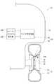
以下、本発明の第1実施形態を図1〜図3に基づいて説明する。図1に示すように本実施形態のタイヤ監視システム10は、車両11の各車輪13(図1には1つの車輪13のみが示されている)にそれぞれ設けられたタイヤ圧検出装置30と、車両本体12に設けられた1つのタイヤ受信装置50とからなる。[First Embodiment]
Hereinafter, a first embodiment of the present invention will be described with reference to FIGS. As shown in FIG. 1, the
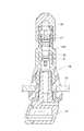
車輪13は、タイヤホイール14のリム14Aにチューブレスのタイヤ15を嵌合して備えている。図2に示すようにリム14Aにはバルブ装着孔14Cが形成され、そのバルブ装着孔14Cにタイヤバルブ16が固定されている。タイヤバルブ16は、両端が開放した筒状のバルブステム16Aの内部に逆止弁構造のバルブコア17を備えている。そして、タイヤバルブ16の先端部がリム14Aの内周面側に突出する一方、タイヤバルブ16の基端部がリム14Aの外周面側に突出してタイヤ15内に配置されている。また、タイヤバルブ16の外面には雄螺子部16Bが形成され、その雄螺子部16Bの先端部にキャップ18が螺合されている。 The
各車輪13に設けられたタイヤ圧検出装置30は、タイヤバルブ16の基端部に固定されてタイヤ15内に配置された検出装置本体部31と、タイヤバルブ16の雄螺子部16Bに螺合固定されてタイヤ15外に配置されたRFIDアッシ20とからなる。 The tire
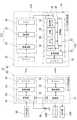
検出装置本体部31は、タイヤバルブ16に固定されたケース37の内部に回路基板38、ボタン電池39及びアンテナ35を収容して備えている。図3に示すように、回路基板38には、メモリ36、制御部32、無線回路33、圧力センサ40、温度センサ41及び加速度センサ42が実装され、回路基板38上の回路がボタン電池39から受電して作動する。また、制御部32と無線回路33とによって本発明に係る検出データ送信部31Sが構成されている。 The detection device
メモリ36は、後述するRFIDタグ21に備えたメモリ26と共に本発明に係る「識別データ記憶部」を構成し、このメモリ36に各タイヤ圧検出装置30毎に設定された識別データが記憶されている。 The
圧力センサ40は、圧力に応じて電気抵抗が変化する図示しない感圧素子と、その電気抵抗の変化を電圧信号にする図示しない検出回路とからなる。ここで所定範囲の圧力をp、その圧力pに対する圧力センサ40の出力電圧をE1、所定の係数K1とすると、下記関係式(1)が成立するように圧力センサ40が設計されている。ところが、実際の圧力センサ40の出力電圧E2は、下記関係式(2)に示したように、設計上の圧力センサ40の出力電圧E1に対して誤差定数C1分がオフセットする。この誤差定数C1は所定範囲の圧力pに対しては一定値であるが、各圧力センサ40毎によってばらつく。 The
E1=K1・p ・・・・(1)
E2=K1・p+C1=E1+C1 ・・・・(2)E1 = K1 · p (1)
E2 = K1.p + C1 = E1 + C1 (2)
また、温度センサ41は、温度に応じて電気抵抗が変化する図示しない感温素子と、その電気抵抗の変化を電圧信号にする図示しない検出回路とからなる。そして、所定範囲の温度をt、その温度tに対する温度センサ41の出力電圧をE11、所定の係数K2とすると、下記関係式(3)が成立するように温度センサ41が設計されている。そして、温度センサ41に関しても同様に、実際の温度センサ41の出力電圧E12は、下記関係式(4)に示したように、設計上の温度センサ41の出力電圧E11に対して誤差定数C2分がオフセットする。 The
E11=K2・t ・・・・(3)
E12=K2・t+C2=E11+C2 ・・・・(4)E11 = K2 · t (3)
E12 = K2 · t + C2 = E11 + C2 (4)
制御部32は、車輪13の回転により加速度センサ42が遠心力を検出したことを条件に所定のプログラムを実行し、圧力センサ40及び温度センサ41の出力電圧E2,E12の値を検出データとして取り込む。そして、制御部32は、それら検出データに前記した識別データを付加して、無線回路33により無線信号してアンテナ35から送信する。 The
図2に示すように、RFIDアッシ20は、タイヤバルブ16の雄螺子部16Bの基端部に螺合固定されたリング部材19と、リング部材19に固定されたアンテナ25及び本発明に係る「トランスポンダ」としてのRFIDタグ21からなる。リング部材19の外周面には環状溝19Aが形成され、アンテナ25は環状溝19A内に電線を巻回してなる。そして、RFIDタグ21はアンテナ25の外周面に固定され、これらRFIDタグ21及びアンテナ25を覆うようにして、環状溝19Aがモールド樹脂19Bにて埋められている。 As shown in FIG. 2, the
図3に示すように、RFIDタグ21には、メモリ26、制御部22、無線回路23及び整流回路24が備えられている。そして、制御部22と無線回路23とから本発明に係る補正データ送信部21Sが構成されている。 As shown in FIG. 3, the
RFIDタグ21のメモリ26は、本発明に係る「補正データ記憶部」に相当すると共に前記検出装置本体部31のメモリ36と共に「識別データ記憶部」を構成し、そのメモリ36と同一の識別データを記憶している。また、メモリ26には、各タイヤ圧検出装置30毎の圧力センサ40に固有の補正データと温度センサ41に固有の補正データとが記憶されている。具体的には、圧力センサ40に固有の補正データとして前記した誤差定数C1が記憶され、温度センサ41に固有の補正データとして前記した誤差定数C2が記憶されている。 The
整流回路24は、外部から受けた電波によりアンテナ25に電磁誘導された交流電圧を直流電圧に変換して制御部22に付与する。これにより制御部22が作動して所定のプログラムを実行し、アンテナ25が受信した電波に含まれる情報を無線回路23を通して取得する。このとき取得した情報にデータ送信命令が含まれていた場合には、制御部22は、メモリ26から補正データ(即ち、誤差定数C1,C2)と識別データとを読み込む。そして、制御部22は、補正データに識別データを付加し、無線回路23により無線信号にしてアンテナ25から送信する。また、取得した情報にデータ更新命令と更新データとが含まれていた場合には、メモリ26に記憶されている補正データ及び/又は識別データを更新データ通りに更新する。 The
このように本実施形態のタイヤ圧検出装置30は、圧力センサ40及び温度センサ41の検出誤差を含んだ検出データを無線送信すると共に、それら圧力センサ40及び温度センサ41の検出誤差に対応した補正データを無線送信する構成になっている。 As described above, the tire
タイヤ受信装置50は、検出データ処理部51と補正データ取得部61とからなる。これら検出データ処理部51と補正データ取得部61とは車両本体12に備えたバッテリー69から電力を受けて作動し、検出データ処理部51がタイヤ圧検出装置30の検出装置本体部31と無線信号を送受信する一方、補正データ取得部61がタイヤ圧検出装置30のRFIDタグ21と無線信号を送受信する。 The
具体的には、補正データ取得部61は、所謂、タグリーダー/ライターであって、アンテナ65と無線回路63と制御部62とを備えている。制御部62は、通常は、データ送信命令を含めた信号を無線回路63により無線信号にしてアンテナ65から出力する。そして、これに応答してRFIDタグ21が出力した無線信号を受信し、その無線信号に含まれる補正データ及び識別データを取得する。また、補正データ取得部61は、外部端末68が接続可能となっており、その外部端末68が補正データ取得部61に更新データを付与すると、制御部62がデータ更新命令及び更新データを無線回路63にて無線信号にしてアンテナ65から出力する。 Specifically, the correction
検出データ処理部51は、制御部52と無線回路53とアンテナ55とを備え、その制御部52が補正データ取得部61の制御部62に接続されている。そして、検出データ処理部51は、タイヤ圧検出装置30から無線送信された検出データを、アンテナ55及び無線回路53を通して検出データ処理部51の制御部52に取り込むと共に、その検出データに付加された識別データと同一の識別データが付加された補正データを、補正データ取得部61から取り込む。詳細には、検出データ処理部51の制御部52は、タイヤ圧検出装置30から無線送信された検出データを取り込んだことを条件にして、補正データ取得部61に補正データを要求する。すると、これに応じて補正データ取得部61が前述の如くデータ送信命令をRFIDタグ21に無線送信し、RFIDタグ21から返信された補正データを検出データ処理部51の制御部52に付与する。 The detection
検出データ処理部51の制御部52は、所定のプログラムを実行し、補正データを用いて検出データを補正する。具体的には、下記演算式(5)のように、圧力センサ40の検出データである前記出力電圧E2から圧力センサ40の補正データである前記誤差定数C1を引く補正を行うと共に、下記演算式(6)のように、温度センサ41の検出データである前記出力電圧E12から温度センサ41の補正データである前記誤差定数C2を引く補正を行う。これにより、圧力センサ40の検出データから検出誤差が排除されると共に、温度センサ41の検出データから検出誤差が排除される。 The
E3 =E2−C1=E1 ・・・・・・・(5)
E13=E12−C2=E11 ・・・・・・・(6)E3 = E2-C1 = E1 (5)
E13 = E12−C2 = E11 (6)
そして、その補正後の値E3,E13にそれぞれ所定の係数を乗じてタイヤ15の内圧及び温度を求め、これら内圧及び温度が、所定の基準値を超えたか否かに基づいて異常の有無を判別する。 Then, the corrected values E3 and E13 are respectively multiplied by a predetermined coefficient to obtain the internal pressure and temperature of the
本実施形態の構成は以上である。次に、上記構成からなる本実施形態の作用効果を説明する。車両11を走行させると4つの車輪13の各タイヤ圧検出装置30が加速度センサ42にて遠心力を検出して圧力センサ40及び温度センサ41の検出データを無線送信する。すると、車両本体12側のタイヤ受信装置50がそれら検出データを受信すると共に、各検出データに対応した補正データをRFIDタグ21から取得する。そして、タイヤ受信装置50が補正データを用いて検出データを補正し、これにより車両本体12側でタイヤ15の正確な内圧及び温度を取得することができる。また、圧力又は温度に異常が有った場合には、タイヤ受信装置50が例えば車両本体12に備えたスピーカー54A(図3参照)から警告音を出力させたり、或いは、車両本体12に備えた表示器54B(図3参照)を用いて警告メッセージを表示する。これにより、タイヤ15の異常に迅速に対応することが可能になる。 The configuration of the present embodiment is as described above. Next, the function and effect of the present embodiment having the above configuration will be described. When the
このように、本実施形態によれば、圧力センサ40及び温度センサ41による検出データのみならず、圧力センサ40及び温度センサ41に固有の検出誤差に対する補正データをタイヤ圧検出装置30から車両本体12に送信するので、車両本体12側で、これら補正データを用いて検出データから検出誤差を排除することができる。これにより、圧力センサ40及び温度センサ41の検出誤差のばらつきに拘わらず、車両本体12側で正確な検出データを取得することができ、従来より検出精度が高くなる。また、従来より検出誤差のばらつきが大きな圧力センサ40及び温度センサ41をタイヤ圧検出装置30に用いて低コスト化を図ることができる。 Thus, according to the present embodiment, not only the detection data by the
しかも、本実施形態の構成によれば、従来のタイヤ圧検出装置にRFIDタグ21を付加して本発明に係るタイヤ圧検出装置30にすることができ、これにより設計作業の簡素化及び従来品の有効利用が図られる。また、RFIDタグ21は受信した電波から電力を取得して作動する構成になっているので、電池切れの心配もない。さらに、タイヤ監視システム10の出荷時やメンテナンス時に、タグリーダー/ライターとしての補正データ取得部61を用いてRFIDタグ21に補正データを容易に書き込むことができる。さらに、本実施形態では、RFIDタグ21を固定したリング部材19をタイヤバルブ16の雄螺子部16Bに螺合した構成になっているので、RFIDタグ21のタイヤバルブ16への取り付け・交換作業を容易に行うことができる。また、量産品のRFIDタグ21を用いて、タイヤ監視システム10のさらなる低コスト化を図ることもできる。 Moreover, according to the configuration of the present embodiment, the
ところで、車両本体12側のタイヤ受信装置50に各圧力センサ40に固有の補正データを記憶しておく構成も考えられるが、本実施形態では、圧力センサ40と補正データを記憶したメモリ26とが共にタイヤ圧検出装置30に備えられて同一の車輪13を固定されるので車輪13を車両本体12と別に流通させても、圧力センサ40と補正データとの整合性が維持される。また、圧力センサ40とRFIDタグ21とがタイヤバルブ16に一体に固定されているので、タイヤ15又はタイヤホイール14の交換が行われても圧力センサ40とRFIDタグ21とが分離されることがない。 By the way, although the structure which memorize | stores the correction data intrinsic | native to each
なお、本実施形態では、検出装置本体部31が電源としてボタン電池39を有していたが、電池を排除し、無線回路33を電源に兼用してもよい。即ち、無線回路33がアンテナ35を通して受信した電波から電力を抽出し、その電力によって検出装置本体部31全体が作動する構成にしてもよい。 In the present embodiment, the detection device
[第2実施形態]
本実施形態のタイヤ監視システム10は、図4に示すように、前記第1実施形態のRFIDタグ21に代えてボタン電池39から電力を受けて作動するトランスポンダ21Aが備えられている。なお、このトランスポンダ21Aは、例えば、ケース37(図2参照)の内部に収容されている。その他の構成は、第1実施形態と同様であるので、第1実施形態と同一の部位に同一符号を付して重複した説明は省略する。本実施形態の構成によっても第1実施形態と同様の作用効果を奏する。[Second Embodiment]
As shown in FIG. 4, the
[他の実施形態]
本発明は、前記実施形態に限定されるものではなく、例えば、以下に説明するような実施形態も本発明の技術的範囲に含まれ、さらに、下記以外にも要旨を逸脱しない範囲内で種々変更して実施することができる。[Other Embodiments]
The present invention is not limited to the above-described embodiment. For example, the embodiments described below are also included in the technical scope of the present invention, and various other than the following can be made without departing from the scope of the invention. It can be changed and implemented.
(1)前記第1実施形態では、RFIDタグ21を固定したリング部材19がタイヤバルブ16に対して離脱可能であったが、タイヤバルブ16を構成するバルブステム16Aの壁部にRFIDタグ21及びアンテナ25を埋設することで、RFIDタグ21及びアンテナ25をタイヤバルブ16に対して離脱不能にしてもよい。この場合、図5に示すようにバルブステム16Aの筒壁部分うちタイヤホイール14の外側に位置した部位にRFIDタグ21及びアンテナ25を埋設してもよいし、図6に示すようにバルブステム16Aの筒壁部分のうちタイヤホイール14の内側に位置した部位にRFIDタグ21及びアンテナ25を埋設してもよい。(1) In the first embodiment, the
(2)また、前記第1実施形態では、RFIDタグ21及びアンテナ25を固定したリング部材19がバルブステム16Aの外側に嵌合されていたが、図7に示すようにRFIDタグ21及びアンテナ25を固定したリング部材19Vをバルブステム16Aの基端部に配置してバルブステム16Aと検出装置本体部31のケース37との間に挟んで固定してもよい。(2) Further, in the first embodiment, although the
(3)また、図8に示すように、タイヤバルブ16の先端部を塞ぐためのキャップ18の天井壁18UにRFIDタグ21及びアンテナ25を埋設してもよい。この場合、バルブステム16Aとキャップ18とを連結片18Aにて連結することで、キャップ18がバルブステム16Aから所定距離以上離れない構成にしておくことが好ましい。(3) Further, as shown in FIG.8 , the
(4)さらに、図9に示すように、キャップ18の開放端に延長筒部18Vを一体形成し、その延長筒部18VにRFIDタグ21及びアンテナ25を埋設してもよい。(4) Further, as shown in FIG.9 , an
(5)また、第1実施形態のタイヤ圧検出装置30のうち検出装置本体部31をタイヤバルブ16に固定する一方、RFIDタグ21を車輪13のうちタイヤバルブ16から離れた部位(例えば、タイヤ15、タイヤホイール14の外面)に固定してもよい。 (5) In addition, the detection device
(6)本発明は、電池を有したタイヤ圧検出装置、電池を有しないタイヤ圧検出装置の何れに適用してもよい。また、電池を有しないタイヤ圧検出装置に関しては、RFID方式よって作動するもの、共振方式よって作動するものの何れに本発明を適用してもよい。 (6) The present invention may be applied to either a tire pressure detecting device having a battery or a tire pressure detecting device having no battery. In addition, regarding a tire pressure detection device that does not have a battery, the present invention may be applied to any one that operates by an RFID method and one that operates by a resonance method.
10 タイヤ監視システム
12 車両本体
13 車輪
15 タイヤ
16 タイヤバルブ
16B 雄螺子部
18 キャップ
19 リング部材
21 RFIDタグ
21A トランスポンダ
21S 補正データ送信部
23 無線回路(補正データ送信回路)
26 メモリ(識別データ記憶部,補正データ記憶部)
30 タイヤ圧検出装置
31S 検出データ送信部
33 無線回路(検出データ送信回路)
36 メモリ(識別データ記憶部、補正データ記憶部)
37 ケース
40 圧力センサ
50 タイヤ受信装置
51 検出データ処理部
61 補正データ取得部DESCRIPTION OF
26 memory (identification data storage unit, correction data storage unit)
30 tire
36 memory (identification data storage unit, correction data storage unit)
37
Claims (11)
Translated fromJapanese前記タイヤ(15)の内圧を検出する圧力センサ(40)と、前記圧力センサ(40)による検出データを車両本体(12)に無線送信する検出データ送信部(31S)とを有してなる検出装置本体部(31)を備えると共に、
前記圧力センサ(40)に固有の検出誤差に対する補正データを記憶した補正データ記憶部(26)と、前記車両本体(12)側から出力された無線信号に応じて前記補正データを前記車両本体(12)に無線送信する補正データ送信部(21S)とを有してなるトランスポンダ(21,21A)を、前記検出装置本体部(31)と兼用せずに別個に設けたことを特徴とするタイヤ圧検出装置(30)。A tiretire pressure detector that will be fixed to the wheel (13) including (15)(30),
A pressure sensor (40) for detecting the internal pressure of the tire(15), wherein thedetection data transmitter for the detection data wirelessly transmitted to the vehicle body (12) by the pressure sensor (40)(31S) andcomprising a detection A device body (31) is provided,
A correction data storage unit (26) that stores correction data for a detection error inherent to the pressure sensor (40), and the correction data according to a radio signal output from the vehicle main body (12) side. 12) A transponder (21, 21A) having a correction data transmission unit (21S) for wireless transmission is provided separately from the detection device main body (31). Pressure detector (30).
前記タイヤ受信装置(50)は、無線信号を出力して前記トランスポンダ(21,21A)に前記補正データを送信させてその補正データを受信する補正データ取得部(61)と、前記検出データ送信部(31S)から前記検出データを受信すると共に前記補正データ取得部(61)から前記補正データを取得し、その補正データに基づいて前記検出データを補正する検出データ処理部(51)とを備えてなることを特徴とするタイヤ監視システム(10)。The tire receiving device (50) includes a correction data acquisition unit (61) that outputs a radio signal, causes the transponders (21, 21A) to transmit the correction data and receives the correction data, and the detection data transmission unit. A detection data processing unit (51) that receives the detection data from (31S), acquires the correction data from the correction data acquisition unit (61), and corrects the detection data based on the correction data. A tire monitoring system (10) characterized in that
前記補正データ取得部(61)は、前記検出データ処理部(51)からの要求に応じて前記補正データを前記トランスポンダ(21,21A)に送信させて受信しかつ前記検出データ処理部(51)に付与するように構成されたことを特徴とする請求項8に記載のタイヤ監視システム(10)。The detection data processing unit (51) requests the correction data from the correction data acquisition unit (61) on the condition that the detection data is received,
The correction data acquisition unit (61) transmits and receives the correction data to the transponder (21, 21A) in response to a request from the detection data processing unit (51), and the detection data processing unit (51). The tire monitoring system (10) according to claim 8, wherein the tire monitoring system (10)is configured to be applied to the tire.
Priority Applications (4)
| Application Number | Priority Date | Filing Date | Title |
|---|---|---|---|
| JP2006028519AJP4633642B2 (en) | 2006-02-06 | 2006-02-06 | Tire pressure detecting device and tire monitoring system |
| US11/486,263US7513145B2 (en) | 2006-02-06 | 2006-07-14 | Tire pressure detecting device and tire monitor system |
| DE602006014929TDE602006014929D1 (en) | 2006-02-06 | 2006-07-18 | Tire pressure detection device and tire monitoring system |
| EP06014961AEP1816014B1 (en) | 2006-02-06 | 2006-07-18 | Tire pressure detecting device and tire monitor system |
Applications Claiming Priority (1)
| Application Number | Priority Date | Filing Date | Title |
|---|---|---|---|
| JP2006028519AJP4633642B2 (en) | 2006-02-06 | 2006-02-06 | Tire pressure detecting device and tire monitoring system |
Publications (2)
| Publication Number | Publication Date |
|---|---|
| JP2007204006A JP2007204006A (en) | 2007-08-16 |
| JP4633642B2true JP4633642B2 (en) | 2011-02-16 |
Family
ID=38016862
Family Applications (1)
| Application Number | Title | Priority Date | Filing Date |
|---|---|---|---|
| JP2006028519AExpired - Fee RelatedJP4633642B2 (en) | 2006-02-06 | 2006-02-06 | Tire pressure detecting device and tire monitoring system |
Country Status (4)
| Country | Link |
|---|---|
| US (1) | US7513145B2 (en) |
| EP (1) | EP1816014B1 (en) |
| JP (1) | JP4633642B2 (en) |
| DE (1) | DE602006014929D1 (en) |
Cited By (1)
| Publication number | Priority date | Publication date | Assignee | Title |
|---|---|---|---|---|
| JP2013531256A (en)* | 2010-07-16 | 2013-08-01 | クーライト・セミコンダクター・プロダクツ・インコーポレーテッド | Pressure scanner assembly with replaceable sensor plate |
Families Citing this family (20)
| Publication number | Priority date | Publication date | Assignee | Title |
|---|---|---|---|---|
| JP2005216077A (en)* | 2004-01-30 | 2005-08-11 | Bridgestone Corp | Bar code label with built-in rfid, tire and management method therefor |
| JP4522953B2 (en)* | 2005-06-22 | 2010-08-11 | 太平洋工業株式会社 | Tire valve unit |
| US8330594B2 (en)* | 2006-01-30 | 2012-12-11 | Sanyo Electric Co., Ltd. | Tire pressure measuring system and tire pressure measuring device |
| US8098146B2 (en) | 2007-10-26 | 2012-01-17 | Measurement Ltd. | Tire pressure monitoring system using wireless network |
| US20110315235A1 (en)* | 2008-08-21 | 2011-12-29 | Warwick Ian Colefax | Valve device for pneumatic tyre including pressure sensor |
| JP5281385B2 (en)* | 2008-12-19 | 2013-09-04 | 株式会社ブリヂストン | Sensor module and tire / wheel assembly provided with sensor module |
| WO2011097823A1 (en)* | 2010-02-12 | 2011-08-18 | 杭州万通气门嘴有限公司 | Inflation valve mounted with electronic box of tire pressure monitoring device |
| JP2013035455A (en)* | 2011-08-09 | 2013-02-21 | Pacific Ind Co Ltd | Tire sensor unit |
| JP6043612B2 (en)* | 2012-12-11 | 2016-12-14 | 太平洋工業株式会社 | Tire condition monitoring device |
| US9248709B2 (en) | 2013-06-13 | 2016-02-02 | Infineon Technologies Ag | RFID-tag, a TPMS device, a tire, a receiver device and a method for providing information related to identification of a tire |
| JP6333205B2 (en)* | 2015-03-23 | 2018-05-30 | 太平洋工業株式会社 | Tire valve |
| TWI573702B (en)* | 2015-10-12 | 2017-03-11 | Mobiletron Electronics Co Ltd | Tire pressure sensor burner |
| GB2545693B (en)* | 2015-12-22 | 2020-05-20 | Schrader Electronics Ltd | Advanced tire monitoring system |
| EP3225432B1 (en)* | 2016-02-03 | 2019-07-03 | Pacific Industrial Co., Ltd. | Tire valve unit |
| FR3077768B1 (en)* | 2018-02-09 | 2020-01-17 | Continental Automotive France | ELECTRONIC UNIT FOR MEASURING OPERATING PARAMETERS OF A VEHICLE WHEEL, INCLUDING AN ELECTRONIC UNIT AND AN ELASTIC DEFORMATION TYPE INFLATION VALVE |
| TWI656044B (en)* | 2018-02-27 | 2019-04-11 | 為升電裝工業股份有限公司 | Tire pressure detector with housing protection |
| US20210206406A1 (en)* | 2018-05-25 | 2021-07-08 | Kawasaki Jukogyo Kabushiki Kaisha | Wheelset rfid tag unit |
| US11987081B2 (en) | 2020-08-27 | 2024-05-21 | The Goodyear Tire & Rubber Company | Tire pressure monitoring system |
| US12115821B2 (en) | 2021-07-02 | 2024-10-15 | The Goodyear Tire & Rubber Company | Tire pressure monitoring system employing axle cross comparison |
| CN114523806B (en)* | 2022-01-28 | 2024-04-19 | 芯安微众(上海)微电子技术有限公司 | Tire pressure memory reporting information processing method, device and storage medium |
Family Cites Families (28)
| Publication number | Priority date | Publication date | Assignee | Title |
|---|---|---|---|---|
| EP0301443B1 (en) | 1987-07-23 | 1993-09-29 | Bridgestone Corporation | Tire inspection device |
| US4966034A (en)* | 1988-04-28 | 1990-10-30 | Schrader Automotive, Inc. | On-board tire pressure indicating system performing temperature-compensated pressure measurement, and pressure measurement circuitry thereof |
| DE4303591C2 (en) | 1993-02-08 | 1996-02-22 | Alpha Beta Electronics Ag | Valve cap with a device for generating a pressure indication signal for a vehicle tire equipped with a valve |
| DE4303583C2 (en) | 1993-02-08 | 1996-02-22 | Alpha Beta Electronics Ag | Valve with a device for generating a wirelessly transmitted pressure decrease signal for vehicle tires |
| US6087930A (en) | 1994-02-22 | 2000-07-11 | Computer Methods Corporation | Active integrated circuit transponder and sensor apparatus for transmitting vehicle tire parameter data |
| US5825286A (en)* | 1995-05-08 | 1998-10-20 | Semisystems, Inc. | Vehicular data collection and transmission system and method |
| ES2139399T3 (en)* | 1995-12-12 | 2000-02-01 | Beru Ag | OPERATION PROCEDURE FOR DEVICES IN WHEELS WITH TIRES TO SIGNAL THE PRESSURE OF THESE LASTS. |
| US5977870A (en) | 1997-12-22 | 1999-11-02 | Bridgestone/Firestone, Inc. | Method and apparatus for transmitting stored data and engineering conditions of a tire to a remote location |
| US6486776B1 (en)* | 1998-04-14 | 2002-11-26 | The Goodyear Tire & Rubber Company | RF transponder and method of measuring parameters associated with a monitored object |
| JP2000103208A (en)* | 1998-09-29 | 2000-04-11 | Pacific Ind Co Ltd | Tire inflation pressure detecting and transmitting device |
| WO2001017806A1 (en) | 1999-09-03 | 2001-03-15 | The Goodyear Tire & Rubber Company | Monitoring a condition of a pneumatic tire |
| AU6248999A (en) | 1999-09-15 | 2001-04-17 | Goodyear Tire And Rubber Company, The | Low pressure warning system (lpws) for pneumatic tires |
| JP3842495B2 (en)* | 1999-10-12 | 2006-11-08 | 太平洋工業株式会社 | Tire pressure monitoring device |
| DE60142907D1 (en) | 2000-07-26 | 2010-10-07 | Bridgestone Americas Tire | ELECTRONIC TIRE HANDLING SYSTEM |
| US6463798B2 (en)* | 2001-01-17 | 2002-10-15 | Microchip Technology Incorporated | Tire inflation pressure monitoring and location determining method and apparatus |
| US20020092347A1 (en)* | 2001-01-17 | 2002-07-18 | Niekerk Jan Van | Radio frequency identification tag tire inflation pressure monitoring and location determining method and apparatus |
| US6571617B2 (en)* | 2001-01-17 | 2003-06-03 | Microchip Technology Incorporated | Method and apparatus using directional antenna or learning modes for tire inflation pressure monitoring and location determination |
| JP2002211219A (en) | 2001-01-22 | 2002-07-31 | Rct:Kk | Tire monitor |
| JP4554827B2 (en)* | 2001-01-24 | 2010-09-29 | 本田技研工業株式会社 | Wheel pressure sensor mounting structure |
| JP2002264617A (en) | 2001-03-07 | 2002-09-18 | Hanex Co Ltd | Structure for installing rfid tag on tire |
| US6683537B2 (en) | 2001-03-29 | 2004-01-27 | The Goodyear Tire And Rubber Company | System of apparatus for monitoring a tire condition value in a pneumatic tire |
| US6400261B1 (en) | 2001-03-29 | 2002-06-04 | The Goodyear Tire & Rubber Company | Method of monitoring a tire condition using a drive over reader |
| JP3949568B2 (en) | 2002-12-09 | 2007-07-25 | 太平洋工業株式会社 | Transponder for tire condition monitoring device |
| JP2004258992A (en)* | 2003-02-26 | 2004-09-16 | Pacific Ind Co Ltd | Tire condition monitoring device and transmitter thereof |
| JP2005043282A (en)* | 2003-07-24 | 2005-02-17 | Pacific Ind Co Ltd | Transmitter of tire status monitor, receiver of the tire status monitor |
| JP2005096726A (en) | 2003-08-25 | 2005-04-14 | Mitsubishi Materials Corp | Tire condition measuring rfid system, rfid tag, and tire valve fitted with rfid tag |
| JP4018617B2 (en)* | 2003-10-10 | 2007-12-05 | 太平洋工業株式会社 | Transmitter for tire condition monitoring device |
| JP2005193743A (en) | 2004-01-05 | 2005-07-21 | Bridgestone Corp | Vehicle tire |
- 2006
- 2006-02-06JPJP2006028519Apatent/JP4633642B2/ennot_activeExpired - Fee Related
- 2006-07-14USUS11/486,263patent/US7513145B2/ennot_activeExpired - Fee Related
- 2006-07-18EPEP06014961Apatent/EP1816014B1/ennot_activeCeased
- 2006-07-18DEDE602006014929Tpatent/DE602006014929D1/enactiveActive
Cited By (1)
| Publication number | Priority date | Publication date | Assignee | Title |
|---|---|---|---|---|
| JP2013531256A (en)* | 2010-07-16 | 2013-08-01 | クーライト・セミコンダクター・プロダクツ・インコーポレーテッド | Pressure scanner assembly with replaceable sensor plate |
Also Published As
| Publication number | Publication date |
|---|---|
| US20070180901A1 (en) | 2007-08-09 |
| EP1816014A3 (en) | 2009-06-17 |
| DE602006014929D1 (en) | 2010-07-29 |
| EP1816014A2 (en) | 2007-08-08 |
| JP2007204006A (en) | 2007-08-16 |
| EP1816014B1 (en) | 2010-06-16 |
| US7513145B2 (en) | 2009-04-07 |
Similar Documents
| Publication | Publication Date | Title |
|---|---|---|
| JP4633642B2 (en) | Tire pressure detecting device and tire monitoring system | |
| US5483827A (en) | Active integrated circuit transponder and sensor apparatus for sensing and transmitting vehicle tire parameter data | |
| EP0746475B1 (en) | Active integrated circuit transponder and method for transmitting vehicle tire parameter data | |
| JP4827837B2 (en) | Tire sensor system and tire used therefor | |
| US8289144B2 (en) | Tire parameter monitoring system with sensor location using RFID tags | |
| US5731754A (en) | Transponder and sensor apparatus for sensing and transmitting vehicle tire parameter data | |
| US5559484A (en) | Data logging tire monitor with condition predictive capabilities and integrity checking | |
| JP4517610B2 (en) | Tire state quantity detection device | |
| US20190126694A1 (en) | Tire Sensor Location Method and Apparatus | |
| JP6450839B2 (en) | Bolt, control device, and strain measurement system | |
| US20020084896A1 (en) | Tire condition sensor communication with tire location provided via vehicle-mounted identification units | |
| US8866591B2 (en) | Identification device for a pneumatic spring | |
| US9731564B2 (en) | Method for associating tire positions on a vehicle having a tire pressure monitoring system | |
| US9426587B2 (en) | Electronics in a receiver-in-canal module | |
| EP2028026A2 (en) | Tire parameter monitoring system with sensor location using magnetic fields | |
| KR20110112400A (en) | Degradation Detection System for Hose Assembly | |
| JP4833196B2 (en) | Sensor abnormality determination device and sensor abnormality determination method | |
| JP5519127B2 (en) | Tire information detection system | |
| JP2000203221A (en) | Pneumatic pressure monitoring unit for spare tire | |
| JP2004145551A (en) | Sensor system | |
| US12420601B2 (en) | Embedded connecting arrangement for tire pressure measuring system | |
| JP2006250641A (en) | Device and method for determining sensor abnormality | |
| JP2005193743A (en) | Vehicle tire | |
| JP2009126316A (en) | Tire information detection device and valve cap | |
| KR20130066368A (en) | Apparatus and method for sensing tire force in vehicle |
Legal Events
| Date | Code | Title | Description |
|---|---|---|---|
| A621 | Written request for application examination | Free format text:JAPANESE INTERMEDIATE CODE: A621 Effective date:20071115 | |
| A977 | Report on retrieval | Free format text:JAPANESE INTERMEDIATE CODE: A971007 Effective date:20100330 | |
| A131 | Notification of reasons for refusal | Free format text:JAPANESE INTERMEDIATE CODE: A131 Effective date:20100512 | |
| A521 | Request for written amendment filed | Free format text:JAPANESE INTERMEDIATE CODE: A523 Effective date:20100708 | |
| TRDD | Decision of grant or rejection written | ||
| A01 | Written decision to grant a patent or to grant a registration (utility model) | Free format text:JAPANESE INTERMEDIATE CODE: A01 Effective date:20101110 | |
| A01 | Written decision to grant a patent or to grant a registration (utility model) | Free format text:JAPANESE INTERMEDIATE CODE: A01 | |
| A61 | First payment of annual fees (during grant procedure) | Free format text:JAPANESE INTERMEDIATE CODE: A61 Effective date:20101117 | |
| R150 | Certificate of patent or registration of utility model | Ref document number:4633642 Country of ref document:JP Free format text:JAPANESE INTERMEDIATE CODE: R150 Free format text:JAPANESE INTERMEDIATE CODE: R150 | |
| FPAY | Renewal fee payment (event date is renewal date of database) | Free format text:PAYMENT UNTIL: 20131126 Year of fee payment:3 | |
| R250 | Receipt of annual fees | Free format text:JAPANESE INTERMEDIATE CODE: R250 | |
| R250 | Receipt of annual fees | Free format text:JAPANESE INTERMEDIATE CODE: R250 | |
| R250 | Receipt of annual fees | Free format text:JAPANESE INTERMEDIATE CODE: R250 | |
| R250 | Receipt of annual fees | Free format text:JAPANESE INTERMEDIATE CODE: R250 | |
| R250 | Receipt of annual fees | Free format text:JAPANESE INTERMEDIATE CODE: R250 | |
| R250 | Receipt of annual fees | Free format text:JAPANESE INTERMEDIATE CODE: R250 | |
| R250 | Receipt of annual fees | Free format text:JAPANESE INTERMEDIATE CODE: R250 | |
| LAPS | Cancellation because of no payment of annual fees |