JP4633212B2 - Shoulder joint prosthesis - Google Patents
Shoulder joint prosthesisDownload PDFInfo
- Publication number
- JP4633212B2 JP4633212B2JP32174299AJP32174299AJP4633212B2JP 4633212 B2JP4633212 B2JP 4633212B2JP 32174299 AJP32174299 AJP 32174299AJP 32174299 AJP32174299 AJP 32174299AJP 4633212 B2JP4633212 B2JP 4633212B2
- Authority
- JP
- Japan
- Prior art keywords
- head
- stem
- kit
- offset
- implant
- Prior art date
- Legal status (The legal status is an assumption and is not a legal conclusion. Google has not performed a legal analysis and makes no representation as to the accuracy of the status listed.)
- Expired - Fee Related
Links
Images


Landscapes
- Prostheses (AREA)
Description
Translated fromJapanese【0001】
【発明の属する技術分野】
本発明は、概して、骨用プロテーゼに関するものであり、より詳細には、肩関節用プロテーゼに関するものである。
【0002】
本発明は、1998年3月17日出願の米国特許出願シリアル番号第09/040,504号および1998年10月2日出願の米国特許出願シリアル番号第09/165,475号の一部継続出願である。
【0003】
【従来の技術および発明が解決しようとする課題】
股関節や肩関節といったような関節が、関節炎や病気や傷害等によって損傷したときには、関節機能を回復するために、関節の全部または一部をプロテーゼでもって置き換えることが必要な場合がある。例えば、大腿骨頭を置換するためにプロテーゼが使用されるような、また場合によっては寛骨臼の全部または一部を置換するためにプロテーゼが使用されるような、股関節置換は、年配の患者の大腿骨頭の骨折や関節炎の処置に際して、通常の処置方法となってきている。解剖学的制約のためにまた肩という困難部位のために、肩関節のインプラントは、歴史的に見て、成功率が少なく、股関節の代替ほどは一般的とはなっていない。しかしながら、最近、深刻な関節炎や上腕骨頭の骨折のための治療方法として容認できる肩関節形成術が出現した。
【0004】
肩関節用プロテーゼの許容度の増大の結果として、発生した様々な問題を解決するために、また、さらなる利点や特長を付与するために、様々なデバイスが開発されている。最も単純な形態においては、肩関節用プロテーゼは、関節窩に対して関節結合するためのヘッドと上腕骨の骨髄管内へと下方延出し上腕骨頭を支持するためのステムとを有してなる単一ピースとして形成される。構成は単純ではあるけれども、単一型インプラントは、様々な患者の関節どうしの間において存在するサイズや形状に関しての個体差に適合するための、自在な調節性をもたらさない。これら個体差に適合するためには、大量のデバイスをストックとして製造しなければならず、手術時に適切な適合が得られることを常に保証しなければならない。単一ピース構成とされたデバイスを大量にストックとして保有することは、かなり割高であり、場合によっては、外科医が、患者に対しての理想的適合を得るための十分な余裕度を有しないこともあり得る。
【0005】
単一型プロテーゼの大量のストックを維持するという割高さを避けるために、また、外科医の余裕度を向上させるために、多くの肩関節用インプラントの製造業者は、手術時に組み立てるタイプの2〜3個の部材からなるモジュール型構成を模索している。これら部材としては、関節窩に対して関節結合するためのヘッドと、ヘッドを搭載して骨に対して固定するためのステム構造と、を備えている。場合によっては、ステムは、ヘッドと、ステムのうちの、骨髄管へと下方延出している中央骨髄部と、の間に、個別のボディを備えている。モジュール型構成を利用することにより、ほんの数個の部材から、様々なデバイスを組み立てることができる。これにより、解剖学的個体差に適合するための余裕度(フレキシブルさ)が向上するとともに、単一ピース型デバイスを選択するための大量にストックすることに関連するコストの大部分を削減することができる。
【0006】
現存する肩関節用のモジュール型構成は、最も一般的には、ヘッドをインプラントの残部に対して固定するに際しては、テーパーロック機構に依存している。少なくともいくつかのデバイスにおいては、テーパーロックのうちの、ヘッド上に位置する部分は、上腕骨頭の背面側解剖学的オフセットを補償するために、オフセットされている。例えば、ヘッド上におけるテーパーロック部は、2〜4mmだけオフセットされることができる。ヘッドを回転させることにより、±2〜4mm以内の任意のオフセットを得ることができる。うまくないことに、オフセットヘッドの回転は、前面側/背面側位置が調節されるのと同時に、内側/外側オフセット、および/または、上側/下側オフセットを引き起こしてしまう。また、テーパロックの中央とヘッドの幾何形状的中央との間のオフセットは、ヘッドをインプラントの残部に対して回転させてしまう傾向のあるトルクを引き起こす。これにより、ヘッドが緩んでしまう可能性が増大してしまう。オフセットが大きくなるにつれて、その結果として生じるトルクも、それにつれて大きくなる。これは、大きなオフセットの場合ほど、重大な問題となる。このような問題は、現存のオフセット型ヘッド構成においては不可避であるけれども、背面側オフセットは、一般に、解剖学的形状に良好に適合させるためには、望ましいものである。
【0007】
現存する様々なインプラント構成に関連した特定の欠点に加えて、肩関節の代替に固有の一般的問題が、いくつか存在する。特に、上腕骨のインプラントに関しては、適正な位置および向きを確立することが一般に困難である。重要な変数のうちの1つは、上腕骨上におけるヘッドの回転位置、すなわち、後傾である。解剖学的には、解剖学的骨頭の周縁部によって形成される平面と曲げた前腕部との間の平均後傾は、約30°である。うまくないことに、現存のインプラントおよびその設置技術では、所望の後傾を信頼性高く再現することは、非常に困難であるとされている。適切な後傾を確立することは、重要である。というのは、不適切な後傾は、その後の変位という問題を引き起こしかねないからである。
【0008】
インプラントの後傾に加えて、上腕骨幹上におけるインプラントの高さを適正なものとして確立することが必要である。現存の構成では、外科医は、ステムを骨髄管内へと滑入し、適切な高さを、経験に基づく推量で決める。高過ぎると、三角筋に過剰な張力がかかることとなる。一方、インプラントを上腕骨内に深く挿入し過ぎると、三角筋のラグ(lag) を引き起こすこととなる。同様に、ステムに対してのヘッド面のオフセットが、適切に確立されなければならない。そうでなければ、回旋腱板の張力が、大きすぎたり足りなかったりしてしまうこととなる。うまくないことに、現存の構成では、最終設置に先立ってインプラントの高さやヘッドのオフセットを評価する手段がない。最終設置後の修正は、困難である。
【0009】
【課題を解決するための手段】
本発明は、ヘッドと;このヘッドに対しての連結のための基端部、および、上腕骨の骨髄管内に挿入するための先端部、および、基端部と先端部との間に配置された位置合わせ部を有した、長尺ステムと;を具備してなる肩関節用プロテーゼである。位置合わせ部は、予め決定された位置において骨内にプロテーゼを配置し得るよう設けられた複数の参照マークを備えている。
【0010】
【発明の実施の形態】
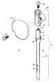
図1は、本発明に基づいて構成されたモジュール型肩関節用インプラントを示す分解斜視図である。
図2は、本発明に基づいて構成されたモジュール型肩関節用インプラントキットを示す図である。
図3は、図1のインプラントにおけるシャフトを示す断面図である。
図4〜図9は、図1のインプラントにおけるボディを示す様々な図である。
図10〜図13は、図1のインプラントにおけるヘッドを示す様々な図である。
図14は、図10〜図13のヘッドの背面を示す斜視図である。
図15は、ボディ上に部分的に設置されたヘッドを示す斜視図である。
図16は、図3における8−8線に沿った、インプラントの断面図である。
図17は、図1のインプラントを示す正面図である。
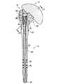
図18は、本発明による目標捕捉/設置器具を示す斜視図である。
図19は、図18の目標捕捉/設置器具を示す側面図である。
図20は、図18の目標捕捉/設置器具を示す平面図である。
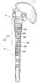
図21は、図1のインプラントの組立状態を示す斜視図である。
図22は、インプラントを示す正面図であって、参照マークを示している。
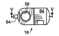
図23は、本発明に基づいて構成されたボディを示す正面図である。
図24は、本発明に基づいて構成されたヘッドの背面を示す背面図である。
図25は、図23における25−25線に沿った断面図である。
【0011】
本発明に基づいて構成された肩関節用インプラントが、図1において、全体的に、符号10によって示されている。インプラント10は、ヘッド12とステム14とを具備している。ステム14は、好ましくは、先端シャフト16とボディ18とを備えている。インプラント10を構成するこれら構成要素は、好ましくは、図2に示すような、相互交換可能とされた、複数のシャフト、複数のボディ、および、複数のヘッドからなるキット20の中から選択される。キット20から適切なシャフト、ボディ、ヘッドを選択することにより、外科医は、ほとんどすべての患者に対してそれぞれ適切なサイズのインプラントを構成することができる。ここで使用される、例えば、前面側/背面側、内側/外側、および、基端側、基端/先端、といった位置に関する用語は、インプラントが患者に対して配置された状態を想定したものであることに注意されたい。
【0012】
シャフト16は、図3に詳細に示すように、基端側テーパー端部30を備えている。基端側テーパー状端部30は、段部32へと向けて先端側へと延在している。段部32は、先細り形状とされて、先端固定穴36,38が形成されている円筒状中央領域34に対して円滑に連接されている。図2からわかるように、シャフトは、様々な直径および/または様々な長さとされた中央領域を有することができる。一般的に言えば、より長いシャフトは、基端側での外傷に加えて、中央部で骨折している場合に、使用される。様々な直径の短いシャフトは、上腕骨の基端部のサイズの個体差に適合するために、使用される。穴36,38のうちの一方または双方は、固定ネジを超えた中央領域の移動を可能とするよう、長尺形状とすることができる。このことは、インプラントが中央領域骨折の組合せを処置するために使用される場合には、一般に望ましいことである。
【0013】
丸められたテーパー状先端40が、中央領域34の先端に形成されている。シャフト16は、好ましくは、ガイドワイヤを使用して上腕骨内へとインプラントを案内するために使用することができる中央管腔42を備えている。図1に示すように、段部32には、後述するように、謝状に対してのボディの向きを適切に確立するのに有用な位置決めノッチ44が、形成されている。テーパー状端部30には、ボディをテーパー状端部に対して緊密に固定するために使用されるネジ50を受領するための、ネジ穴46が形成されている。段部32からわずかに先端側のところには、張力バンドワイヤのインプラントを通しての固定を可能とするよう、ワイヤ穴48が形成されている。加えて、インプラントが所定位置にセメントで固定されるときには、セメントの硬化時にインプラントの位置を固定し得るよう、上腕骨および穴48を通して、K−ワイヤを操作することができる。
【0014】
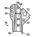
図1に示すように、ボディ18は、シャフト16の頂部に取り付けられる。図4〜図9に示すように、ボディ18は、先端54を有している。この先端54からは、ボディの内部に向けて上向きに延在するテーパー状ソケット56が形成されている。ソケット56は、シャフト16のテーパー状端部30を受領し得るようなサイズとされており、ボディをシャフトに対して固定するためのテーパーロックを個別に設置し得るようなサイズとされている。ソケット56からボディの頂部に向けては、ソケット内においてボディをシャフト頂部と係合させるための上記固定ネジ50のための、基端穴58が延在している。この基端穴58内には、固定ネジ50のヘッドを係止するための、小さなリブ60が設けられている。
【0015】
ボディ18の先端から下方に向けては、ソケットの近傍において、ボディがシャフト上に設置された際に位置決めノッチ44に対して係合するための、小さなフィンガー62が形成されている。これについては、図1および図17を参照されたい。これは、シャフトに対してのボディの回転角度位置の決定を適正なものとすることを保証する。ボディ18は、さらに、3つの縫合穴66が形成されている側方リブ64を備えている。縫合穴66は、骨折破片をインプラントに対して固定するために利用することができる。また、上側縫合穴68および下側縫合穴70が、骨折破片のさらなる固定を行い得るよう、ボディ18に設けられている。ボディ18には、ヘッドをボディに対して固定するためのネジを受領するための、中間位置に配置され、前面側を向いてネジ山が形成されている、ネジ穴72が形成されている。穴72は、また、インプラントと共に使用される目標捕捉/設置器具のための取付ポイントとしても機能する。穴72の頂部には、凹所74が形成されている。凹所74には、目標捕捉/設置器具の位置決めのための、キーノッチ76が形成されている。これについては、図1および図4を参照されたい。凹所74は、ステムを上腕骨内に挿入するために必要な骨切除量を最小化し得るよう、ネジのヘッドが、ボディの表面と実質的に面一とされた状態で設置されることを可能とする。
【0016】
ボディ18は、ヘッド12が取り付けられることとなる基端部のところに、内側を向いて傾斜した取付面80を備えている。ヘッド12は、取付面80上に位置したペデスタルまたは鳩の尾の形状の取付具を備えた結合構造82を介して、ボディ18に対して固定される。図6および図8に示すように、鳩尾形状部84は、後述するように、ヘッドの対してのテーパーロックを確立するよう、前面側から背面側にかけて、テーパー状とされている。鳩尾形状部がテーパーとされていることにより、ボディは、適用される肩が左肩であるかまたは右肩であるかに依存して、左右の方向性を有している(左肩用または右肩用とされている)。よって、図2に示すように、キットは、好ましくは、2つまたはそれ以上のボディを備えている。1個の左肩用ボディと1個の右肩用ボディとだけでなく、様々なステム径やヘッド角度等に対応できるよう、さらなるボディを準備しておくことができる。
【0017】
2つまたはそれ以上の部材の組立によって形成されているのではなく好ましくは単一部材として形成されているヘッド12は、肩関節内の関節窩に係合し得る形状とされた全体的に半球状の関節面90を備えている。これについては、図10〜図13を参照されたい。関節窩が、例えば股関節の寛骨臼に見られるような密着結合タイプのソケットではないことにより、関節面は、関節窩内における円滑な関節結合を可能とするに十分な球形であることだけが必要である。
【0018】
図14に明瞭に示すように、関節面90には、ヘッド軸96に対してほぼ直交する関節平面94を形成する関節結合マージン領域92が、連接されている。好ましい実施形態においては、ヘッドが実質的に球形である場合には、ヘッド軸は、関節面の回転対称軸をなす中央軸である。そして、湾曲中心98は、このヘッド軸上に位置している。これについては、図11を参照されたい。図13において破線で示すように、同じ半径であっても異なる膨出度合いとされた様々なヘッドが形成されることが好ましい。このことが、実際の解剖学的特性に適合するものであると信じられている。
【0019】
最も一般的に発生する骨折パターンにおいては、解剖学的骨頭は、通常、関節結合マージン領域および関節平面を通して骨折する。関節平面は、通常、ヘッド12の先端膨出度合いを決定する。このことは、修正手術の一部としてヘッドを取り外す必要がある場合に、重要である。というのは、本発明においては、関節や関連した損傷部分を変位させることなく、前面側からヘッドを取り外し得るからである。このことは、まず最初に関節を変位させることによってしかボディからのヘッドの取外しを行えないような現存のインプラントヘッドとは、相違している。必須ではないけれども、本発明においては、ヘッドが関節平面を超えて実質的に突出しないことが望ましい。その場合には、周囲の骨の分解を要することなく、関節からヘッドをスライドによって取り外すことができる。上腕部の残部が、関節平面よりも先端側であることにより、ヘッドが関節平面を実質的に超えて突出していない限りにおいては、周囲の骨を分解する必要なく、関節平面内においてヘッドをスライドさせることができる。よって、結合構造は、ヘッドをステム上に設置するために、また、インプラントが肩関節に設置された後において肩関節を変位させることなくステムからヘッドを取り外すために、使用することができる。
【0020】
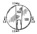
ヘッド12は、関節面とは反対側に、取付面すなわち背面100を備えている。背面100は、関節結合マージン領域を介することで、関節面とは隔離されている。背面100は、横方向トラックまたはアンダーカットチャネル102の形態で、結合構造82の一部を備えている。チャネル102は、鳩尾形状部84の断面形状およびテーパー形状に適合し得るようカットされている。チャネル102は、開放端部104と、内側端部106と、を備えている。円筒状凹所108が、ヘッドの周縁部を起点とし、チャネルの内側端部を超えて、係止部110を終点として、延在している。凹所108内には、ヘッドのエッジの近傍において、グルーブ112が形成されている。
【0021】
チャネル102は、ヘッドがボディ上を案内されかつチャネル内に鳩尾形状テーパーロックが案内されこれによりヘッドが適正に配置されるような、サイズとされている。これについては、図10を参照されたい。テーパーロック結合は、テーパーロック結合が部材どうしを堅固に固定して、互いに緩むことを防止し、さらに、経時的に破片を生成しないことのために、重要である。本発明による結合構造は、テーパーロックの一部がヘッド上に配置されかつテーパーロックの一部がボディ上に配置されていることにより、横方向に作用するテーパーロックと見なすこともできる。本発明によるテーパーロックは、従来構成とは異なり、ロックを行うためにヘッド軸に沿った移動を必要とはしないという点において、横方向作用である。実際、ヘッドがステム上に係合しているときには、結合構造は、ヘッドが関節平面を横切る方向に移動しないよう、機械的にロックする。これは、現存の構成とは相違する点である。現存の構成では、関節平面を横切る方向における単なる摩擦係合に依存している。
【0022】
ネジ114の形態としての固定部材が、テーパーロックを適正に機能させた状態で、ヘッドをボディ上に堅固に固定するために設けられている。特に、ヘッド12が、図15に示すようにして、ボディ上に初期的に配置されたときには、ヘッドを、所定位置にまで全体的にスライドさせることができ、ネジ114を、ネジのヘッドが円筒状凹所108内に密接に適合した状態で、穴72内に螺合させることができる。これについては、図16を参照されたい。ネジを締め込んだときには、ネジのヘッドは、係止体110に係止される。これにより、ヘッド12がボディ18上に堅固に固定される。ネジ114は、また、ヘッドが変位してしまわないことを保証するバックアップインターロックとして機能する。結合構造における機械加工誤差を許容するためのいくらかのクリアランスを残しておくこと必要があることにより、ネジのヘッドは、ボディに対して完全には着座しないことに注意されたい。これにより、すべての場合においてテーパーロックが密着的に機能することが保証される。
【0023】
修正時に、ヘッドを取り外す必要が生じた場合には、先端近傍にフランジ122が固定されているツール120が使用される。図16を参照されたい。まず最初に、ツールの先端が、ヘッドに対してわずかに斜めの角度位置からネジヘッド内に係合し、その後、フランジを、凹所108内に形成されているグルーブ112の形態とされた取外し補助面に対して係合させ、それから、ツールを回転させる。ネジが引き抜かれるにつれて、フランジが、ヘッドを引っ張って、テーパーロックを変位させる。よって、ヘッドを、従来構成でも必要とされていたようなインプラントに対しての外力を利用して取り外すことができる。このことは、ヘッドだけを取り外す必要がある場合に、インプラント全体が緩んでしまう可能性を低減させる。
【0024】
本発明によるインプラントの設置は、図18において全体的に符号130で示すような、目標捕捉/設置器具を使用して行われる。器具130は、テンプレート部材132を備えている。テンプレート部材には、取付バー134と、高さ調節機構136と、後傾ガイド138と、が設けられている。取付バー134は、テンプレート部材132とインプラント10とを連結するよう機能する。特に、バー134は、中空であって、自由端にタブ140(図示せず)を備えている。バー134は、ヘッド144とネジ山付き端部146とを有したボルト142を受領している。この器具をインプラントに対して取り付けるには、バー134の自由端部を、凹所74内に配置し、タブ140がキーノッチ76に嵌合するようにして、位置決めする。これにより、テンプレート部材とインプラントとの間の適正な位置合わせが確立される。それから、ボルト142のネジ山付き端部を、ネジ穴72内に螺着し、器具をインプラントに対して固定する。バー134は、ヘッド12を取り付けない状態で、バーのボディ18に対しての到達を可能とする平面148を備えている。加えて、ヘッドをボディに対して固定するためのボルトは、器具が取り外されるまでは、装着されないことに注意されたい。
【0025】
器具がインプラントに対して取り付けられると、ステムが、上腕骨幹内に挿入される。典型的な骨折のパターンにおいては、ヘッドと多くのまたはわずかの結節とが上腕骨の残部から剥離していて、パイプ状の上側幹が残されている。その結果、上腕骨幹に対してのインプラントヘッドの適正高さを参照するためのものが残されていない。ヘッドを上腕骨幹に対する適正高さで配置することは、ヘッドが高すぎて三角筋に過度の張力がかかったりあるいは逆にヘッドが低すぎて腕を移動させる前に三角筋がいくらか収縮しなければならず三角筋がラグ(lag) を起こしたりするのを避けるという意味において、重要である。
【0026】
高さ調節機構は、外科医が、ヘッドの高さを一時的にセットすることを可能とし、これにより、外科医は、その高さでの三角筋の張力を評価することができる。特に、図18および図19に示すように、高さ調節機構136は、ガイドバー150を備えている。ガイドバー150は、キャリッジ152に対して移動可能に取り付けられている。キャリッジ152は、ネジ山付きロッド154に沿って昇降駆動される。上腕骨幹156内におけるインプラントに対して、ガイドバー150は、上腕骨幹の頂部158上に当接するようにして配置される。この場合、外科医は、ネジ山付きロッドを回転させることで、インプラントを、上下方向に位置調節することができる。ガイドバーは、所定高さを確立することができる。このようにして確立された所定高さは、後傾がセットされる際にも、骨用セメントを使用する場合にインプラントを引き抜いて再挿入する場合においてさえも、維持することができる。
【0027】
適正高さを決定した後に、外科医は、図20に示すように、後傾ガイドを使用することによって、適正な後傾をセットすることができる。後傾ガイドは、下部照準アーム162を有しているL字形ロッド160を備えている。ロッド160は、照準アーム162の高さおよび角度位置を調節できるよう、テンプレート132に対して、回転可能かつスライド可能に取り付けられている。セットネジ164は、ロッドが所望配置とされたときに、ロッドの位置を固定することができる。使用時には、照準アームが、例えば30°といったような、ヘッド軸に対しての所定後傾角度をなすように、セットされる。これは、分度器(図示せず)を使用して、インプラントに対しての取付前に、行っておくことができる。照準アームを適正配向にセットした状態で、患者の前腕が、上腕骨に対して約90°をなすように、曲げられる。この状態で、外科医は、インプラントを回転させて、照準アームを前腕軸に対して位置合わせする。これにより、所望の後傾を、容易にかつ精度良く確立することができる。
【0028】
適正高さおよび適正な後傾が確立されると、ドリル用中空ガイド170が、テンプレート部材の先端部に形成されたガイド穴172を通して挿入される。図18を参照されたい。ガイド穴172は、ステムの端部における固定穴36を向いている。ドリル174が、ドリル用中空ガイドを通して挿入され、これにより、、固定穴を貫通する貫通穴が骨を貫通して開けられる。1つまたは2つのネジが、上腕骨および固定穴を通して挿入され、インプラントの所定位置での固定が行われる。
【0029】
図19において破線で示すように、ヘッドの固定に先立って、大きな結節159をインプラントに対して取り付けることができる。これにより、外科医は、回旋腱板の張力を評価することができ、必要であれば、ヘッドを多少動かして修正を行うことができる。本発明の他の特徴点は、図21に示すように、縫合サポート180を設けることである。縫合サポート180は、縫合力を、骨上にわたって分散させるよう機能する。特に外傷の場合には、骨は非常に柔らかく、サポート180を設置しなければ、縫合糸が、骨内に食い込むこともあり得る。サポートを使用することによって、外科医は、骨表面を通して縫合糸が引っ張られること(骨内への縫合糸の食い込み)というリスクを冒すことなく、所望の縫合張力を得ることができる。
【0030】
目標捕捉/設置器具は、左用と右用とを準備することができること、あるいは、左用ボディと右用ボディとの双方に適合し得るよう、取付バー134を可逆構造すなわち対象構造とすることができること、に注意されたい。さらに、中央部分の骨折を処置するために長尺シャフトが適用される場合には、長尺のテンプレート部材を使用することができる。
【0031】
インプラントの設置および位置合わせは、また、図22において符号200で示すように、インプラント上に、表示すなわち参照マークを配置することによっても、行うことができる。参照マーク200は、ステムの位置合わせ部分202に配置されている。一般的には、ステムのうちの、インプラントの設置時に上腕骨幹の頂部近傍に位置すると思われる領域内に配置される。好ましくは、参照マークは、高さと角度配向との双方を観測できるよう、角度位置表示204や鉛直方向に隔離された複数の段階表示206といったような、1つまたは複数の角度マークを備えることができる。鉛直方向に隔離された複数の段階表示に対しては、特定の表示を容易に認識できるよう、例えば文字208といったような複数の記号を付加することができる。これら参照マークは、インプラントの表面に対してレーザーによって描画することもできるし、インプラントに対するエッチングによって描画することもできるし、また、他の任意の描画プロセスによって描画することができる。マークや記号は、通常、前面側から見えるものであって、したがって、前面に配置されることが好ましいものである、ことに注意されたい。左肩または右肩上に配置されるインプラントの場合には、マークや記号は、好ましくは、インプラントの左右両側面上に形成することができる。こうすることで、どちらの肩に配置して場合でも、マークや記号を見ることができる。
【0032】
使用時には、外科医は、まず最初に、1つまたは複数の試行用プロテーゼを使用し、上述のようにして、試行用プロテーゼを適正に設置する。試行用プロテーゼは、典型的には、実際のプロテーゼと同じものである。しかしながら、試行用プロテーゼは、複数の手術間にわたって再使用するためのキットから組み立てられる。試行用プロテーゼには、実際のプロテーゼと同じ位置に、参照マークが設けられている。適正な取付および配置が確立されると、外科医は、どの段階表示が上腕骨幹の頂部のところに位置しているかを書き留めておく。そして、外科医は、上腕骨幹の頂部のうちの、角度表示に一致している箇所に、メチレンブルー色素でもって、マークを付けておく。その後、外科医は、実際のプロテーゼを試行用プロテーゼと置き換え、実際のプロテーゼを、試行用プロテーゼの場合と同じ位置において上腕骨内に配置する。この場合、先に書き留めておいた段階表示と、先に決定しておいた骨の一致箇所とを、実際のインプラントにおいて位置合わせすることによって、角度配向と深さ位置とが再現される。
【0033】
位置合わせマークは、モジュール型インプラントにおいても単一型インプラントにおいても採用できること、また、位置合わせマークは、単独で使用することができ、あるいは、上述の目標捕捉器具と組み合わせても使用することができること、を理解されたい。さらに、このようなマークは、試行用デバイスを使用しない場合であってさえも、所望に配置された後にインプラントが動いていないことを確認できることにより、有利である。
【0034】
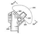
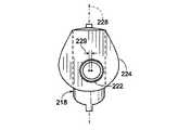
本発明による肩関節用インプラントと共に使用し得るボディの他の実施形態が、図23において符号218で示されている。ボディ218は、ボディ18と同様の構成とされている。しかしながら、ボディ218は、取付上面280上に形成されたテーパー形状スタッド222を備えている。ヘッド212は、スタッド222上において取り付けることによって、ボディ218に対して取り付けられ得るよう構成されている。より詳細には、ヘッド212は、スタッド222に対して適合するとともにスタッド222と協働してテーパーロックを形成するようなサイズとされた、テーパー形状穴226を備えている。このテーパーロックによって、ヘッドとボディとが固定される。カラー224は、取付面280の下側境界を形成している。図24を参照されたい。このカラーは、ボディが上腕骨内へと沈降するのを防止するよう機能するとともに、テーパーロックを緩めてしまう傾向を有しているような外力がヘッドに対してかかるのを防止するよう機能する。
【0035】
図25に明瞭に示すように、テーパー形状スタッドの軸は、ボディおよびステムの前面側/後面側に関しての中央面228から、オフセットされている(ずらされている)。図示実施形態においては、符号229によって示されているオフセット量は、埋設されたときの後面側方向へと、約2mmである。一般に、適切なオフセット量は、約1〜5mmである。オフセットの結果として、左肩用ボディと右肩用ボディとが、区別される。オフセットがなければ、左肩用ボディと右肩用ボディとは、互いに鏡像関係である。
【0036】
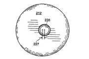
図示実施形態においては、テーパー形状穴は、図24において符号227で示すように、ヘッドの中心から約1mmだけオフセットされている。このオフセットにより、外科医は、ヘッドを回転させることによって、約1〜3mmの間において任意の所望のオフセット量を得ることができる。テーパー形状スタッドを前面側/後面側中央面からオフセットさせていることにより、外科医は、過度の上側/下側オフセットを導入することなく、ある範囲の後面側オフセットを得ることができる。オフセットを有したヘッドが例示されているけれども、ヘッドがオフセットを有さないこともできる。その場合には、一切の上側/下側オフセットを除去することができる。ヘッドのオフセットを除去することの利点は、ヘッドの位置に他の擾乱を起こすことなく、ボディを介して所望の前面側/後面側オフセットを導入できることである(ボディの前面側/後面側オフセット量だけによって、ヘッドの前面側/後面側位置が決定されることである)。このことは、一般に、オフセットによって生成されるトルクを低減し得るよう、ヘッドオフセットを最小に維持できるという点において望ましい。
【0037】
ボディを左肩用および右肩用に区別できることに加えて、複数の左肩用および右肩用ボディに、様々なオフセットを設けることが望ましい。ヘッドは、ボディを製造するよりも実質的にコスト高であるので、多数のボディを準備することは、幅広い範囲にわたる解剖学的オフセットを得るためには、より経済的な方策である。ボディは、バーストックからの機械加工によって製造することができ、また、鋳造によって製造することができる。左肩用または右肩用を特定したボディを準備することの他の利点は、調節可能なボディに比較して、ボディのサイズを最小に維持できることである。ボディサイズの最小化は、インプラントの設置に際しての骨切削量を低減する。
【0038】
円筒状テーパーロックに関連して説明した前面側/後面側オフセットは、ヘッドにおいてあるいはボディにおいてあるいは双方において単にテーパーロックをオフセットすることにより、上述の鳩尾形状テーパーロックにおいても採用できることに注意されたい。
【0039】
本発明を好ましい形態について説明してきたけれども、ここで開示され例示された本発明の特定の実施形態は、多数の変形が可能であるという点において、本発明を制限するものではないと考えるべきである。出願人は、本発明の主題を、ここで開示した様々な構成要素、特徴点、機能、および/または、特性の、新規なかつ非自明な任意の組合せを含むものとして、とらえている。どの単独の、特徴点、機能、構成要素、あるいは、特性も、必須というわけでもない。添付の請求範囲は、新規かつ非自明と見なし得るある種の組合せを、規定している。特徴点、機能、構成要素、および/または、特性の他の組合せは、本出願または関連出願において、現在の請求範囲の補正によってまたは新規請求範囲の提案によって、主張することができる。当初の請求範囲と比較して、より広い、あるいは、より狭い、あるいは、同等の範囲とされたそれら新たな請求範囲も、また、本発明の主題として見なされる。
【図面の簡単な説明】
【図1】 本発明に基づいて構成されたモジュール型肩関節用インプラントを示す分解斜視図である。
【図2】 本発明に基づいて構成されたモジュール型肩関節用インプラントキットを示す図である。
【図3】 図1のインプラントにおけるシャフトを示す断面図である。
【図4】 図1のインプラントにおけるボディを示す正面図である。
【図5】 図1のインプラントにおけるボディを示す側断面図である。
【図6】 図1のインプラントにおけるボディを示す右側面図である。
【図7】 図1のインプラントにおけるボディを示す左側面図である。
【図8】 図1のインプラントにおけるボディを示す平面図である。
【図9】 図1のインプラントにおけるボディを示す背面図である。
【図10】 図1のインプラントにおけるヘッドを示す背面図である。
【図11】 図1のインプラントにおけるヘッドを示す側断面図である。
【図12】 図1のインプラントにおけるヘッドを示す正面図である。
【図13】 図1のインプラントにおけるヘッドを示す様々な側断面図である。
【図14】 図10〜図13のヘッドの背面を示す斜視図である。
【図15】 ボディ上に部分的に設置されたヘッドを示す斜視図である。
【図16】 図3における8−8線に沿った、インプラントの断面図である。
【図17】 図1のインプラントを示す正面図である。
【図18】 本発明による目標捕捉/設置器具を示す斜視図である。
【図19】 図18の目標捕捉/設置器具を示す側面図である。
【図20】 図18の目標捕捉/設置器具を示す平面図である。
【図21】 図1のインプラントの組立状態を示す斜視図である。
【図22】 インプラントを示す正面図であって、参照マークを示している。
【図23】 本発明に基づいて構成されたボディを示す正面図である。
【図24】 本発明に基づいて構成されたヘッドの背面を示す背面図である。
【図25】 図23における25−25線に沿った断面図である。
【符号の説明】
10 インプラント(肩関節用インプラント、肩関節用プロテーゼ)
12 ヘッド
14 ステム
16 先端シャフト(先端部)
18 ボディ
20 キット
84 鳩尾形状部
100 背面
200 参照マーク
212 ヘッド
218 ボディ
222 スタッド
224 カラー[0001]
BACKGROUND OF THE INVENTION
The present invention relates generally to bone prostheses, and more particularly to shoulder joint prostheses.
[0002]
The present invention is a continuation-in-part of U.S. Patent Application Serial No. 09 / 040,504, filed March 17, 1998, and U.S. Patent Application Serial No. 09 / 165,475, filed Oct. 2, 1998. It is.
[0003]
[Background Art and Problems to be Solved by the Invention]
When a joint such as a hip joint or a shoulder joint is damaged due to arthritis, illness, injury, or the like, it may be necessary to replace all or part of the joint with a prosthesis in order to restore joint function. For example, hip replacement is used in older patients, such as when a prosthesis is used to replace the femoral head, and in some cases, the prosthesis is used to replace all or part of the acetabulum. It has become a common treatment method for the treatment of femoral head fractures and arthritis. Due to anatomical constraints and because of the difficult part of the shoulder, shoulder implants have historically been less successful and are not as common as hip replacements. Recently, however, shoulder arthroplasty has emerged as an acceptable treatment for severe arthritis and humeral head fractures.
[0004]
As a result of the increased tolerance of shoulder prostheses, various devices have been developed to solve the various problems that have arisen and to provide further advantages and features. In its simplest form, a shoulder prosthesis has a single head comprising a head for articulation to the glenoid and a stem for extending the humerus into the medullary canal and supporting the humeral head. Formed as one piece. Although simple in construction, a single implant does not provide the flexibility to adapt to individual differences in size and shape that exist between various patient joints. In order to adapt to these individual differences, a large number of devices must be manufactured as stock, and it must always be ensured that an appropriate fit is obtained during surgery. Holding a large number of single piece devices as stock is quite expensive, and in some cases, the surgeon does not have sufficient margin to obtain an ideal fit for the patient. There is also a possibility.
[0005]
In order to avoid the high price of maintaining a large stock of single prosthesis and to improve the surgeon's margins, many shoulder joint implant manufacturers are of the type 2-3 that are assembled during surgery. We are looking for a modular construction consisting of individual members. These members include a head for articulating the glenoid and a stem structure for mounting the head and fixing it to the bone. In some cases, the stem includes a separate body between the head and a central bone marrow portion of the stem that extends down to the medullary canal. By utilizing a modular configuration, various devices can be assembled from just a few members. This increases the margins (flexibility) to fit anatomical individual differences and reduces most of the costs associated with stocking large quantities to select single piece devices. Can do.
[0006]
Existing modular configurations for shoulder joints most commonly rely on a taper locking mechanism to secure the head to the rest of the implant. In at least some devices, the portion of the taper lock located on the head is offset to compensate for the posterior anatomical offset of the humeral head. For example, the taper lock on the head can be offset by 2-4 mm. An arbitrary offset within ± 2 to 4 mm can be obtained by rotating the head. Unfortunately, the rotation of the offset head causes an inner / outer offset and / or an upper / lower offset at the same time that the front / back position is adjusted. Also, the offset between the center of the taper lock and the geometric center of the head causes a torque that tends to cause the head to rotate relative to the rest of the implant. This increases the possibility of the head becoming loose. As the offset increases, the resulting torque increases with it. This becomes a more serious problem with larger offsets. While such problems are unavoidable in existing offset head configurations, backside offsets are generally desirable in order to better fit the anatomy.
[0007]
In addition to the specific drawbacks associated with various existing implant configurations, there are several general problems inherent in shoulder replacement. In particular, for humeral implants, it is generally difficult to establish the proper position and orientation. One of the important variables is the rotational position of the head on the humerus, i.e. the posterior tilt. Anatomically, the average posterior inclination between the plane formed by the peripheral edge of the anatomical head and the bent forearm is about 30 °. Unfortunately, with existing implants and their installation techniques, it is very difficult to reliably reproduce the desired anteversion. It is important to establish a proper retrograde. This is because improper backward tilt can cause problems of subsequent displacement.
[0008]
In addition to implant posterior tilt, it is necessary to establish the proper implant height on the humeral shaft. In the existing configuration, the surgeon slides the stem into the medullary canal and determines the appropriate height with empirical guesses. If it is too high, excessive tension is applied to the deltoid muscle. On the other hand, if the implant is inserted too deeply into the humerus, it will cause deltoid lag. Similarly, the offset of the head surface relative to the stem must be established properly. Otherwise, the tension of the rotator cuff will be too large or insufficient. Unfortunately, with existing configurations, there is no means to assess implant height or head offset prior to final installation. Correction after final installation is difficult.
[0009]
[Means for Solving the Problems]
The invention includes a head; a proximal end for connection to the head; a distal end for insertion into the medullary canal of the humerus; and a proximal end and a distal end. A prosthesis for a shoulder joint, comprising: a long stem having an alignment portion. The alignment portion includes a plurality of reference marks provided so that the prosthesis can be placed in the bone at a predetermined position.
[0010]
DETAILED DESCRIPTION OF THE INVENTION
FIG. 1 is an exploded perspective view showing a modular shoulder joint implant constructed according to the present invention.
FIG. 2 is a diagram showing a modular shoulder joint implant kit constructed according to the present invention.
FIG. 3 is a cross-sectional view showing a shaft in the implant of FIG.
4-9 are various views showing the body in the implant of FIG.
10-13 are various views showing the head in the implant of FIG.
FIG. 14 is a perspective view showing the back surface of the head shown in FIGS.
FIG. 15 is a perspective view showing a head partially installed on the body.
FIG. 16 is a cross-sectional view of the implant taken along line 8-8 in FIG.
FIG. 17 is a front view showing the implant of FIG. 1.
FIG. 18 is a perspective view of a target capture / installation instrument according to the present invention.
19 is a side view of the target capture / installation instrument of FIG.
20 is a top view of the target capture / installation instrument of FIG.
FIG. 21 is a perspective view showing an assembled state of the implant of FIG.
FIG. 22 is a front view showing the implant, and shows reference marks.
FIG. 23 is a front view showing a body constructed according to the present invention.
FIG. 24 is a rear view showing the rear surface of the head constructed according to the present invention.
25 is a cross-sectional view taken along line 25-25 in FIG.
[0011]
A shoulder joint implant constructed in accordance with the present invention is indicated generally by the numeral 10 in FIG. The
[0012]
As shown in detail in FIG. 3, the
[0013]
A rounded tapered
[0014]
As shown in FIG. 1, the
[0015]
From the tip of the
[0016]
The
[0017]
The
[0018]
As clearly shown in FIG. 14, the joint surface 90 is connected to a joint
[0019]
In the most commonly occurring fracture pattern, the anatomical head typically fractures through the joint margin area and the joint plane. The joint plane typically determines the degree of tip bulge of the
[0020]
The
[0021]
The
[0022]
A fixing member in the form of a
[0023]
When it is necessary to remove the head at the time of correction, the
[0024]
The placement of the implant according to the present invention is performed using a target capture / placement instrument, generally designated 130 in FIG. The
[0025]
When the instrument is attached to the implant, the stem is inserted into the humeral shaft. In a typical fracture pattern, the head and many or few nodules are detached from the rest of the humerus, leaving a pipe-like upper trunk. As a result, nothing remains to refer to the proper height of the implant head relative to the humeral shaft. Positioning the head at the correct height relative to the humeral shaft requires that the head is too high and excessive tension is applied to the deltoid muscle, or conversely, the deltoid muscle is somewhat contracted before the arm is moved too low. It is important in that it avoids the deltoid lag.
[0026]
The height adjustment mechanism allows the surgeon to temporarily set the height of the head so that the surgeon can assess the tension of the deltoid muscle at that height. In particular, as shown in FIGS. 18 and 19, the
[0027]
After determining the proper height, the surgeon can set the proper back tilt by using a back tilt guide, as shown in FIG. The rearward tilt guide includes an L-shaped
[0028]
When the proper height and the proper rearward tilt are established, the drill
[0029]
A
[0030]
The target capture / installation instrument can be prepared for left and right use, or the mounting
[0031]
Implant placement and alignment can also be accomplished by placing a display or reference mark on the implant, as shown at 200 in FIG. The
[0032]
In use, the surgeon first uses one or more trial prostheses and properly installs the trial prosthesis as described above. The trial prosthesis is typically the same as the actual prosthesis. However, the trial prosthesis is assembled from a kit for reuse across multiple surgeries. The trial prosthesis is provided with a reference mark at the same position as the actual prosthesis. Once proper attachment and placement is established, the surgeon notes which stage indication is located at the top of the humeral shaft. The surgeon marks the top of the humeral shaft with a methylene blue dye at a position corresponding to the angle display. The surgeon then replaces the actual prosthesis with the trial prosthesis and places the actual prosthesis in the humerus at the same location as the trial prosthesis. In this case, the angular orientation and the depth position are reproduced by aligning the stage display written down earlier and the previously determined bone coincidence position in the actual implant.
[0033]
The alignment mark can be employed in either a modular or single implant, and the alignment mark can be used alone or in combination with the target capture device described above. I want to be understood. Furthermore, such a mark is advantageous by being able to verify that the implant is not moving after it has been placed in the desired manner, even if no trial device is used.
[0034]
Another embodiment of a body that may be used with a shoulder implant according to the present invention is shown at 218 in FIG. The
[0035]
As clearly shown in FIG. 25, the axis of the tapered stud is offset from the
[0036]
In the illustrated embodiment, the tapered hole is offset by about 1 mm from the center of the head, as shown at 227 in FIG. This offset allows the surgeon to obtain any desired amount of offset between about 1-3 mm by rotating the head. By offsetting the tapered stud from the front / rear center plane, the surgeon can obtain a range of rear offsets without introducing excessive upper / lower offsets. Although a head with an offset is illustrated, the head can also have no offset. In that case, any upper / lower offset can be removed. The advantage of removing the head offset is that the desired front side / rear side offset can be introduced through the body without causing other disturbances in the head position (front side / rear side offset amount of the body). Only the position of the front side / rear side of the head is determined). This is generally desirable in that the head offset can be kept to a minimum so that the torque produced by the offset can be reduced.
[0037]
In addition to distinguishing the body for the left shoulder and the right shoulder, it is desirable to provide various offsets for the left and right shoulder bodies. Since the head is substantially more expensive than manufacturing the body, preparing a large number of bodies is a more economical strategy to obtain a wide range of anatomical offsets. The body can be manufactured by machining from bar stock or can be manufactured by casting. Another advantage of preparing a body specifically for the left shoulder or right shoulder is that the size of the body can be kept to a minimum compared to an adjustable body. Minimizing the body size reduces the amount of bone cut during implant placement.
[0038]
Note that the front side / rear side offsets described in connection with the cylindrical taper lock can also be employed in the dovetail taper lock described above by simply offsetting the taper lock at the head and / or the body.
[0039]
Although the present invention has been described with reference to preferred forms, the specific embodiments of the present invention disclosed and illustrated herein should not be construed as limiting the invention in that many variations are possible. is there. Applicants view the subject matter of the present invention as including any novel and non-obvious combination of various components, features, functions, and / or properties disclosed herein. No single feature, function, component, or characteristic is required. The appended claims define certain combinations that may be considered new and non-obvious. Other combinations of features, functions, components, and / or characteristics may be claimed in this or related applications by amending the current claim or by proposing a new claim. These new claims, which are broader, narrower, or equivalent to the original claims, are also considered as subject matter of the present invention.
[Brief description of the drawings]
FIG. 1 is an exploded perspective view showing a modular shoulder joint implant constructed according to the present invention.
FIG. 2 is a diagram showing a modular shoulder joint implant kit constructed according to the present invention.
FIG. 3 is a cross-sectional view showing a shaft in the implant of FIG. 1;
4 is a front view showing a body in the implant of FIG. 1; FIG.
FIG. 5 is a side sectional view showing a body in the implant of FIG. 1;
6 is a right side view showing a body in the implant of FIG. 1. FIG.
7 is a left side view showing a body in the implant of FIG. 1. FIG.
8 is a plan view showing a body in the implant of FIG. 1. FIG.
FIG. 9 is a rear view showing the body in the implant of FIG. 1;
10 is a rear view showing a head in the implant of FIG. 1. FIG.
FIG. 11 is a side sectional view showing a head in the implant of FIG. 1;
12 is a front view showing a head in the implant of FIG. 1; FIG.
13 is various cross-sectional side views showing the head in the implant of FIG. 1. FIG.
14 is a perspective view showing the back surface of the head shown in FIGS. 10 to 13; FIG.
FIG. 15 is a perspective view showing a head partially installed on the body.
16 is a cross-sectional view of the implant taken along line 8-8 in FIG.
17 is a front view showing the implant of FIG. 1. FIG.
FIG. 18 is a perspective view of a target capture / installation instrument according to the present invention.
FIG. 19 is a side view of the target capture / installation instrument of FIG.
20 is a plan view of the target capture / installation instrument of FIG. 18. FIG.
FIG. 21 is a perspective view showing an assembled state of the implant of FIG. 1;
FIG. 22 is a front view showing the implant and showing a reference mark.
FIG. 23 is a front view showing a body constructed according to the present invention.
FIG. 24 is a rear view showing a rear surface of a head configured according to the present invention.
25 is a cross-sectional view taken along line 25-25 in FIG.
[Explanation of symbols]
10 Implant (shoulder joint implant, shoulder joint prosthesis)
12 heads
14 stem
16 Tip shaft (tip)
18 body
20 kits
84 Hatoo shape part
100 back
200 Reference mark
212 heads
218 body
222 Stud
224 colors
Claims (12)
Translated fromJapanese背面を有したヘッドと;
上腕骨の骨髄管内に挿入するための先端部と;
前記ヘッドと前記先端部とを様々な相対位置関係で連結するために使用することができる左肩用ボディおよび右肩用ボディであるとともに、前記先端部に対して連結された状態で各ボディが、長尺ステムを形成するものとされている左肩用ボディおよび右肩用ボディと;
前記ヘッドと前記ステムとを結合するための円錐台形テーパーロック構造と;
を具備してなり、
前記テーパーロック構造は、前記背面に対して直交している軸回りにおける前記ヘッドの回転を引き起こすことなく前記ヘッドを前記ステムに対して連結し得るものであり、
前記テーパーロック構造は、オス型部材およびメス型部材を備え、
これらオス型部材およびメス型部材の一方は、前記ヘッドの前記背面上に配置され、なおかつ、これらオス型部材およびメス型部材の他方は、前記ステムの前記ボディ上に配置され、
前記左肩用ボディが、前記テーパーロック構造のうちの、このボディ上に配置された部分の位置を、左上腕骨内において所定の後面側オフセットでもって位置決めし、
前記右肩用ボディが、前記テーパーロック構造のうちの、このボディ上に配置された部分の位置を、右上腕骨内において所定の後面側オフセットでもって位置決めし、
前記ステムは、このステムの基端部に、前記ステムの上腕骨内への沈降を防止するためのカラーを備えていることを特徴とするキット。A kit for a shoulder joint prosthesis,
A head having a back surface;
A tip for insertion into the medullary canal of the humerus;
A body for a left shoulder and a body for a right shoulder that can be used to connect the head and the tip part in various relative positional relationships, and each body in a state of being connected to the tip part, A left shoulder body and a right shoulder body that are intended to form a long stem;
A frustoconical tapered lock structure for coupling the head and the stem;
Comprising
The taper lock structure can connect the head to the stem without causing rotation of the head around an axis orthogonal to the back surface;
The taper lock structure includes a male member and a female member,
One of the male member and the female member is disposed on the back surface of the head, and the other of the male member and the female member is disposed on the body of the stem,
The left shoulder body positions the portion of the tapered lock structure disposed on the body with a predetermined posterior surface offset in the left humerus,
The right shoulder body positions the portion of the taper lock structure disposed on the body with a predetermined posterior surface offset within the right upper humerus;
The stem is provided with a collar for preventing settling into the humerus of the stem at a proximal end portion of the stem .
前記ステムの基端部と前記先端部との間に配置された位置合わせ部を備え、
この位置合わせ部が、予め決定された位置において骨内にプロテーゼを配置し得るよう設けられた複数の参照マークを備えていることを特徴とするキット。The kit according to claim 1, wherein
An alignment portion disposed between the proximal end portion of the stem and the distal end portion;
The kit, wherein the alignment portion includes a plurality of reference marks provided so that the prosthesis can be placed in the bone at a predetermined position.
前記参照マークは、前記位置合わせ部の少なくとも一部にわたって前記ステムに沿って延在する角度表示を備えていることを特徴とするキット。The kit according to claim 2,
The kit, wherein the reference mark includes an angle display extending along the stem over at least a part of the alignment portion.
前記参照マークは、前記位置合わせ部の少なくとも一部にわたって配置されるとともに前記ステムの軸方向に互いに離間されている鉛直方向離間された複数の段階表示を備えていることを特徴とするキット。The kit according to claim 2,
The kit is characterized in that the reference mark is arranged over at least a part of the alignment portion and includes a plurality of vertically spaced step indications separated from each other in the axial direction of the stem.
前記オス型部材は、前記ステムの基端部上に配置されていることを特徴とするキット。In the kit according to any one of claims 1 to 4,
The kit wherein the male member is disposed on a proximal end portion of the stem.
前記テーパーロック構造のうちの、前記ボディ上に位置する部分の、前記後面側オフセットの量が、1mm以上であることを特徴とするキット。In the kit according to any one of claims 1 to 5,
The kit characterized in that an amount of the rear surface side offset of a portion of the taper lock structure located on the body is 1 mm or more.
前記ヘッドの前記背面が、実質的に円形形状であり、
前記テーパーロック構造のうちの、前記ヘッド上に位置する部分が、前記円形背面の中心からオフセットされていることを特徴とするキット。In the kit according to any one of claims 1 to 6,
The back surface of the head has a substantially circular shape;
The kit wherein the portion of the taper lock structure located on the head is offset from the center of the circular back surface.
前記背面の中心からの前記オフセットの量が、少なくとも約1mmであることを特徴とするキット。The kit according to claim 7, wherein
A kit wherein the amount of the offset from the center of the back is at least about 1 mm.
前記背面の中心からの前記オフセットの量が、約3mm未満であることを特徴とするキット。The kit according to claim 7, wherein
The kit, wherein the amount of the offset from the center of the back surface is less than about 3 mm.
前記ヘッドが、半球状の関節結合面、および、ヘッド軸に対してほぼ直交して配置された背面を備え、さらに、テーパー形状ソケットを備え、
このテーパー形状ソケットが、前記テーパーロック構造の前記メス型部材であるとともに、前記背面から内方側に延在し、
前記ステムが、テーパー形状スタッドを備え、
このテーパー形状スタッドが、前記テーパーロック構造の前記オス型部材であるとともに、前記ステムが上腕骨内に設置されたときに前記ステムによって形成される前面側/後面側中央面に対して平行にオフセットされている軸を規定することを特徴とするキット。In the kit according to any one of claims 1 to9 ,
The head includes a hemispherical articulating surface and a back surface disposed substantially orthogonal to the head axis, and further includes a tapered socket;
This taper-shaped socket is the female member of the taper lock structure, and extends inward from the back surface,
The stem comprises a tapered stud;
The tapered stud is the male member of the tapered lock structure, and is offset in parallel to the front / rear center plane formed by the stem when the stem is installed in the humerus. A kit characterized by defining a fixed axis.
前記スタッド軸は、前記前面側/後面側中央面に対して、少なくとも約1mmだけオフセットされていることを特徴とするキット。The kit according to claim10 , wherein
The kit wherein the stud shaft is offset by at least about 1 mm with respect to the front side / rear side center plane.
前記左肩用ボディおよび右肩用ボディが、互いに鏡像関係であることを特徴とするキット。The kit according to any one of claims 1 to11 ,
The kit according to claim 1, wherein the left shoulder body and the right shoulder body are mirror images of each other.
Applications Claiming Priority (2)
| Application Number | Priority Date | Filing Date | Title |
|---|---|---|---|
| US09/191,928US6102953A (en) | 1998-03-17 | 1998-11-13 | Shoulder prosthesis |
| US191.928 | 1998-11-13 |
Publications (3)
| Publication Number | Publication Date |
|---|---|
| JP2000197651A JP2000197651A (en) | 2000-07-18 |
| JP2000197651A5 JP2000197651A5 (en) | 2006-12-28 |
| JP4633212B2true JP4633212B2 (en) | 2011-02-16 |
Family
ID=22707490
Family Applications (1)
| Application Number | Title | Priority Date | Filing Date |
|---|---|---|---|
| JP32174299AExpired - Fee RelatedJP4633212B2 (en) | 1998-11-13 | 1999-11-11 | Shoulder joint prosthesis |
Country Status (1)
| Country | Link |
|---|---|
| JP (1) | JP4633212B2 (en) |
Families Citing this family (8)
| Publication number | Priority date | Publication date | Assignee | Title |
|---|---|---|---|---|
| US20020016634A1 (en)* | 2000-07-28 | 2002-02-07 | Brian Maroney | Device and method for positioning an eccentric humeral head of a humerus prothesis for a shoulder arthroplasty |
| RU2306904C2 (en)* | 2003-12-19 | 2007-09-27 | Общество с ограниченной ответственностью "Эндосервис" | Endoprosthesis of shoulder joint |
| US7476255B2 (en)* | 2003-12-30 | 2009-01-13 | Depuy Products, Inc. | Soft tissue attachment system and method |
| JP4498909B2 (en)* | 2004-12-21 | 2010-07-07 | ナカシマプロペラ株式会社 | Shoulder prosthesis |
| GB0519994D0 (en)* | 2005-10-01 | 2005-11-09 | Depuy Ireland Ltd | Humeral component of a shoulder joint prosthesis |
| JP2009512522A (en)* | 2005-10-21 | 2009-03-26 | アキュームド・エルエルシー | Orthopedic rod with a clamping opening |
| JP5285227B2 (en)* | 2007-02-26 | 2013-09-11 | 京セラメディカル株式会社 | Bioprosthesis |
| US9044330B2 (en) | 2013-03-12 | 2015-06-02 | DePuy Synthes Products, Inc. | System and method for implanting a secondary glenoid prosthesis |
- 1999
- 1999-11-11JPJP32174299Apatent/JP4633212B2/ennot_activeExpired - Fee Related
Also Published As
| Publication number | Publication date |
|---|---|
| JP2000197651A (en) | 2000-07-18 |
Similar Documents
| Publication | Publication Date | Title |
|---|---|---|
| US6168628B1 (en) | Shoulder Prosthesis | |
| US7297163B2 (en) | Shoulder prosthesis | |
| US11298233B2 (en) | Method of implanting joint prosthesis with infinitely positionable head | |
| EP1417939B1 (en) | Humeral shoulder prosthesis | |
| EP1402854B1 (en) | Reverse-type humeral prosthesis | |
| US20060058886A1 (en) | Tool | |
| JP4397666B2 (en) | Shoulder joint prosthesis and surgical method | |
| JP4633212B2 (en) | Shoulder joint prosthesis | |
| CN1181792C (en) | Tool for controlling included angle between artificial hip joint parts |
Legal Events
| Date | Code | Title | Description |
|---|---|---|---|
| A521 | Request for written amendment filed | Free format text:JAPANESE INTERMEDIATE CODE: A523 Effective date:20061113 | |
| A621 | Written request for application examination | Free format text:JAPANESE INTERMEDIATE CODE: A621 Effective date:20061113 | |
| A871 | Explanation of circumstances concerning accelerated examination | Free format text:JAPANESE INTERMEDIATE CODE: A871 Effective date:20061113 | |
| A975 | Report on accelerated examination | Free format text:JAPANESE INTERMEDIATE CODE: A971005 Effective date:20061206 | |
| A131 | Notification of reasons for refusal | Free format text:JAPANESE INTERMEDIATE CODE: A131 Effective date:20070104 | |
| A521 | Request for written amendment filed | Free format text:JAPANESE INTERMEDIATE CODE: A523 Effective date:20070213 | |
| A131 | Notification of reasons for refusal | Free format text:JAPANESE INTERMEDIATE CODE: A131 Effective date:20070313 | |
| A601 | Written request for extension of time | Free format text:JAPANESE INTERMEDIATE CODE: A601 Effective date:20070612 | |
| A602 | Written permission of extension of time | Free format text:JAPANESE INTERMEDIATE CODE: A602 Effective date:20070615 | |
| A521 | Request for written amendment filed | Free format text:JAPANESE INTERMEDIATE CODE: A523 Effective date:20070911 | |
| A02 | Decision of refusal | Free format text:JAPANESE INTERMEDIATE CODE: A02 Effective date:20071030 | |
| A521 | Request for written amendment filed | Free format text:JAPANESE INTERMEDIATE CODE: A523 Effective date:20071220 | |
| A911 | Transfer to examiner for re-examination before appeal (zenchi) | Free format text:JAPANESE INTERMEDIATE CODE: A911 Effective date:20080407 | |
| A912 | Re-examination (zenchi) completed and case transferred to appeal board | Free format text:JAPANESE INTERMEDIATE CODE: A912 Effective date:20080502 | |
| A601 | Written request for extension of time | Free format text:JAPANESE INTERMEDIATE CODE: A601 Effective date:20100121 | |
| A602 | Written permission of extension of time | Free format text:JAPANESE INTERMEDIATE CODE: A602 Effective date:20100126 | |
| A01 | Written decision to grant a patent or to grant a registration (utility model) | Free format text:JAPANESE INTERMEDIATE CODE: A01 | |
| A61 | First payment of annual fees (during grant procedure) | Free format text:JAPANESE INTERMEDIATE CODE: A61 Effective date:20101117 | |
| R150 | Certificate of patent or registration of utility model | Free format text:JAPANESE INTERMEDIATE CODE: R150 | |
| FPAY | Renewal fee payment (event date is renewal date of database) | Free format text:PAYMENT UNTIL: 20131126 Year of fee payment:3 | |
| S111 | Request for change of ownership or part of ownership | Free format text:JAPANESE INTERMEDIATE CODE: R313113 | |
| FPAY | Renewal fee payment (event date is renewal date of database) | Free format text:PAYMENT UNTIL: 20131126 Year of fee payment:3 | |
| R350 | Written notification of registration of transfer | Free format text:JAPANESE INTERMEDIATE CODE: R350 | |
| R250 | Receipt of annual fees | Free format text:JAPANESE INTERMEDIATE CODE: R250 | |
| LAPS | Cancellation because of no payment of annual fees |