JP4632891B2 - X-ray CT imaging apparatus and X-ray CT imaging method - Google Patents
X-ray CT imaging apparatus and X-ray CT imaging methodDownload PDFInfo
- Publication number
- JP4632891B2 JP4632891B2JP2005213057AJP2005213057AJP4632891B2JP 4632891 B2JP4632891 B2JP 4632891B2JP 2005213057 AJP2005213057 AJP 2005213057AJP 2005213057 AJP2005213057 AJP 2005213057AJP 4632891 B2JP4632891 B2JP 4632891B2
- Authority
- JP
- Japan
- Prior art keywords
- turning
- ray
- axis
- subject
- pivot
- Prior art date
- Legal status (The legal status is an assumption and is not a legal conclusion. Google has not performed a legal analysis and makes no representation as to the accuracy of the status listed.)
- Expired - Lifetime
Links
Images


Classifications
- A—HUMAN NECESSITIES
- A61—MEDICAL OR VETERINARY SCIENCE; HYGIENE
- A61B—DIAGNOSIS; SURGERY; IDENTIFICATION
- A61B6/00—Apparatus or devices for radiation diagnosis; Apparatus or devices for radiation diagnosis combined with radiation therapy equipment
- A61B6/02—Arrangements for diagnosis sequentially in different planes; Stereoscopic radiation diagnosis
- A61B6/03—Computed tomography [CT]
- A61B6/032—Transmission computed tomography [CT]
- A—HUMAN NECESSITIES
- A61—MEDICAL OR VETERINARY SCIENCE; HYGIENE
- A61B—DIAGNOSIS; SURGERY; IDENTIFICATION
- A61B6/00—Apparatus or devices for radiation diagnosis; Apparatus or devices for radiation diagnosis combined with radiation therapy equipment
- A61B6/58—Testing, adjusting or calibrating thereof
- A61B6/589—Setting distance between source unit and patient
Landscapes
- Health & Medical Sciences (AREA)
- Life Sciences & Earth Sciences (AREA)
- Engineering & Computer Science (AREA)
- Medical Informatics (AREA)
- Radiology & Medical Imaging (AREA)
- Molecular Biology (AREA)
- Biophysics (AREA)
- Nuclear Medicine, Radiotherapy & Molecular Imaging (AREA)
- Optics & Photonics (AREA)
- Pathology (AREA)
- Physics & Mathematics (AREA)
- Biomedical Technology (AREA)
- Heart & Thoracic Surgery (AREA)
- High Energy & Nuclear Physics (AREA)
- Surgery (AREA)
- Animal Behavior & Ethology (AREA)
- General Health & Medical Sciences (AREA)
- Public Health (AREA)
- Veterinary Medicine (AREA)
- Pulmonology (AREA)
- Theoretical Computer Science (AREA)
- Apparatus For Radiation Diagnosis (AREA)
- Analysing Materials By The Use Of Radiation (AREA)
Description
Translated fromJapanese本発明は、3次元領域を再構成するX線CT撮影に関するものである。 The present invention relates to X-ray CT imaging for reconstructing a three-dimensional region.
X線コンピュータ断層撮影(CT)装置では、X線発生器とX線検出器を被写体の両側に配置する。そして、X線発生器とX線検出器を被写体の周りで被写体に対して相対的に回転させつつ、X線発生器により被写体に多方向からX線ビームを照射し、被写体を透過したX線の強度分布(被写体の投影)をX線検出器で測定する。そして、1回転で収集されたX線投影データから、被写体の断層面について被写体内部のX線の線吸収係数の分布(画像)を2次元的に再構成して、断層像を得る。この再構成計算を、旋回軸に垂直な複数の面について行う。そして、複数の断層像から3次元画像を得る。 In an X-ray computed tomography (CT) apparatus, an X-ray generator and an X-ray detector are arranged on both sides of a subject. Then, the X-ray generator and the X-ray detector are rotated relative to the subject around the subject, and the subject is irradiated with the X-ray beam from multiple directions by the X-ray generator and transmitted through the subject. Is measured with an X-ray detector. Then, from the X-ray projection data collected in one rotation, the distribution (image) of the X-ray absorption coefficient inside the subject is reconstructed two-dimensionally on the tomographic plane of the subject to obtain a tomographic image. This reconstruction calculation is performed for a plurality of surfaces perpendicular to the pivot axis. A three-dimensional image is obtained from a plurality of tomographic images.
なお、後で説明するように本発明ではX線発生器と撮影上の回転中心との距離および/またはX線検出器と撮影上の回転中心との距離を相対的に変更可能とされるが、これに関連して、特開2004−329293号公報に記載されたCT撮影装置では、CT撮影の前に、X線CT撮影の対象となる目標箇所の3次元位置を正確に位置決めするために、X線発生器と被写体とX線検出器との位置関係を2通りに設定して透過静止画像(スカウト画像という)を撮影する。ここで、スカウト画像の大きさを変える場合、椅子の位置をX線検出器で相対的に移動している。また、工業用の被写体に使用されるX線CT撮影装置(たとえば特開平5−322802号公報参照)では、被写体の両側に配置されるX線発生器とX線検出器の位置は固定され、一方、被写体が、回転テーブルに載せられる。そして、回転テーブルを回転しつつ被写体の投影が撮影される。ここで、X線発生器やX線検出器の回転テーブルに対する位置を変えると倍率が変化できる。また、特開2001−37747号公報には、旋回するリングアームに被写体を挟んで相対向するX線発生部とX線平面検出器を設けたCT撮影装置が開示されている。このX線平面検出器は、伸縮動する伸縮アームを介してリングアームに設けられており、伸縮アームの伸縮動の作用により、X線平面検出器が被写体に近接、離隔し、拡大率が変更可能である。
CT撮影において、拡大率を可変できると、視野(関心領域の大きさ)を可変にでき、また、解像度を可変にできる。X線発生器とX線検出器とが旋回アームやガントリーなどに対向して配置されるCT撮影装置では、X線発生器とX線検出器は、被写体の周りを、X線発生器、被写体及びX線検出器の間の距離を一定に保ちつつ回転される。拡大率は、X線発生器またはX線検出器の被写体に対する距離を変えることにより増減できる。 In CT imaging, if the magnification can be varied, the field of view (the size of the region of interest) can be varied, and the resolution can be varied. In a CT imaging apparatus in which an X-ray generator and an X-ray detector are arranged facing a swivel arm, a gantry, etc., the X-ray generator and the X-ray detector are arranged around the subject with an X-ray generator and a subject. And the X-ray detector is rotated while keeping the distance constant. The enlargement ratio can be increased or decreased by changing the distance of the X-ray generator or X-ray detector to the subject.
しかし、従来の技術においては、次のような問題がある。特開2004−329293号公報に記載されたCT撮影装置では、スカウト画像の大きさは変えられるが、CT画像の拡大率可変構成までは言及されていない。また、たとえば特開平5−322802号公報に記載される、工業用の被写体に使用されるX線CT撮影装置では、被写体を旋回させながら撮影することがCT撮影の条件であるが、撮影対象が物体であるから旋回させながらの撮影が可能なのであり、人体を旋回させつつ撮影することは、身動きから生じるアーチファクトや、被写体が目まいを起こす等の問題があって、特に医療用目的の場合、事実上採用は困難である。さらに、撮影対象が物体であっても、連続回転に耐えない精緻な構造のものであることもあり、同様に採用は困難である。また、たとえば特開2001−37747号公報に記載される、従来のX線CT撮影装置における拡大率可変の構成では、旋回手段に対してX線検出器を移動させる機構や、旋回手段に対してX線発生器を移動させる機構を要する。一方、従来より、旋回アームの両端のそれぞれに、固定的にX線発生器とX線検出器を設けた医療用のパノラマX線撮影やX線CT撮影装置は多く普及しており、改良が望まれていた。 However, the conventional techniques have the following problems. In the CT imaging apparatus described in Japanese Patent Application Laid-Open No. 2004-329293, the size of the scout image can be changed, but no mention is made of a configuration for changing the magnification of the CT image. Further, in the X-ray CT imaging apparatus used for an industrial subject described in, for example, Japanese Patent Laid-Open No. 5-322802, the CT imaging condition is that imaging is performed while turning the subject. Because it is an object, it is possible to shoot while turning, and shooting while turning the human body has problems such as artifacts caused by movement and dizziness of the subject, especially for medical purposes. Top adoption is difficult. Furthermore, even if the object to be photographed is an object, it may be of an elaborate structure that cannot withstand continuous rotation, and is similarly difficult to adopt. Further, for example, in a configuration with a variable magnification in a conventional X-ray CT imaging apparatus described in Japanese Patent Laid-Open No. 2001-37747, a mechanism for moving the X-ray detector relative to the turning means, or a turning means A mechanism for moving the X-ray generator is required. On the other hand, medical panoramic X-ray imaging and X-ray CT imaging apparatuses in which X-ray generators and X-ray detectors are fixedly provided at both ends of the swivel arm have been widely used and improved. It was desired.
本発明の目的は、相対的位置関係が固定されたX線発生器とX線検出器を用いて、CT撮影の視野(関心領域の大きさ)を容易に可変にすることである。 An object of the present invention is to easily change the field of view of CT imaging (the size of a region of interest) using an X-ray generator and an X-ray detector whose relative positional relationship is fixed.
本発明に係るX線CT装置は、X線発生器とX線検出器とが被写体を挟んで対向するように配置された旋回アームからなる旋回手段と、前記旋回アームを前記X線発生器とX線検出器との間の位置で旋回可能に軸支する機構上の旋回軸を含み、前記旋回アームを前記機構上の旋回軸の軸心を中心に旋回する旋回機構と、前記旋回アームを回転可能に支持する支持体と、前記支持体に固定され、前記支持体に相対的に前記機構上の旋回軸を前記機構上の旋回軸に垂直な方向に交差する2次元の方向に移動させる旋回軸移動機構と、X線CT撮影中に前記旋回機構と前記旋回軸移動機構を制御し、前記旋回機構による前記旋回アームの旋回及び前記旋回軸移動機構による前記機構上の旋回軸の移動の連動による合成運動を行わせる制御装置とを備える。前記旋回機構において前記機構上の旋回軸は鉛直方向に配置される。ここで、前記制御装置は、前記合成運動において、前記旋回機構に、前記X線発生器とX線検出器を、前記機構上の旋回軸を旋回の中心として旋回させるのと同時に同期して、前記旋回軸移動機構に、関心領域の中心に対する前記X線発生器及び前記X線検出器の距離を常に一定に保つように、前記機構上の旋回軸を、前記関心領域の中心を円の中心とする円周上を移動させる。これにより、前記X線発生器と前記回転中心との距離および/または前記X線検出器と前記回転中心との距離を相対的に変更可能とすることにより拡大率を変更可能にする。EngagingRu X-ray CT apparatus in the present invention, the X-ray generator and the X-ray detector and the swivelingmeans comprising swivel arms arrangedso as to face each other across the subject,the X-ray generator and said pivot arm and it comprises a pivot axis on the mechanism for pivotally journalled at a location between the X-ray detector, a turningmechanism for turningthe swivel armabout the axis of the pivoton themechanism,the swivel arm a support for rotatably supporting a is fixed to the support, moving the pivot axisonrelatively themechanismto the support in two-dimensional directions crossingthe direction perpendicular to the pivot axison themechanism A turning axis moving mechanism for controlling the turning mechanism and the turning axis moving mechanism during X-ray CT imaging, turning of the turningarm by the turning mechanism and movementof the turning axison the mechanism by the turning axis moving mechanism Equipped with a control device that performs synthetic motion by interlocking That.In the turning mechanism, the turning axis on the mechanism is arranged in the vertical direction. Here, in the synthetic motion, the control devicesynchronizes with the turning mechanism simultaneously with the turning of the X-ray generator and the X-ray detector around the turning axis on the mechanism as the turning center. In order to keep the distance of the X-ray generator and the X-ray detector relative to the center of the region of interestto the pivot axis moving mechanism,the pivot axis on the mechanism is set to the center of the circle. Move on the circumference . Accordingly, the enlargement ratio can be changed by relatively changing the distance between the X-ray generator and the rotation center and / or the distance between the X-ray detector and the rotation center.
好ましくは、前記X線CT撮影装置において、前記旋回軸移動機構は、前記旋回機構の前記旋回軸を第1の方向に移動可能な第1移動手段と、前記第1の方向と異なる第2の方向に移動可能な第2移動手段とを備える。 Preferably, in the X-ray CT imaging apparatus, the turning shaft moving mechanism includes a first moving means capable of moving the turning shaft of the turning mechanism in a first direction, and a second different from the first direction. Second moving means movable in the direction.
また、好ましくは、前記X線CT撮影装置において、前記旋回軸移動機構が前記旋回機構と同じハウジング内に設けられる。 Preferably, in the X-ray CT imaging apparatus, the turning shaft moving mechanism is provided in the same housing as the turning mechanism.
また、好ましくは、前記X線CT撮影装置において、前記旋回軸移動機構は、前記旋回機構の前記旋回軸の軸受けに結合された1つ又は複数の直列に接続された結合部材により構成され、前記回転中心を前記旋回軸に交差する2次元の方向に移動可能とする。 Preferably, in the X-ray CT imaging apparatus, the turning shaft moving mechanism is constituted by one or a plurality of connecting members connected in series connected to a bearing of the turning shaft of the turning mechanism, The center of rotation can be moved in a two-dimensional direction intersecting the pivot axis.
好ましくは、前記X線CT撮影装置は、さらに、前記被写体を、前記機構上の旋回軸に交差する2次元の方向に移動させる被写体移動機構を備える。前記制御装置は、X線CT撮影中に前記旋回機構と前記旋回軸移動機構および前記被写体移動機構に、前記旋回機構による前記旋回手段の旋回と、前記旋回軸移動機構および前記被写体移動機構による前記機構上の旋回軸および前記被写体の移動との連動による合成運動により、前記合成運動において、前記機構上の旋回軸を、前記円周上を相対的に移動させることを特徴とする。Preferably, the X-ray CT imaging apparatusfurther includes a subject moving mechanismthat moves the subject in a two-dimensional direction that intersects a turning axison the mechanism. The control device,the pivot mechanism and the pivot axis moving mechanismand the object moving mechanism in the X-ray CTimaging, a turning of the turning meansby the turning mechanism, theby the pivot movement mechanismand the object moving mechanism a synthetic movement by interlocking with movement of the pivot axisand the objecton the mechanism,in the synthetic motion, a pivoton said mechanism, characterized inthat makesrelatively movingsaid circumference on.
本発明に係るX線CT撮影方法では、X線発生器とX線検出器とが被写体を挟んで対向するように配置された旋回アームからなる旋回手段と、前記旋回アームを前記X線発生器とX線検出器との間の位置で旋回可能に軸支する機構上の旋回軸を含み、前記旋回アームを前記機構上の旋回軸の軸心を中心に旋回する旋回機構と、前記旋回アームを回転可能に支持する支持体と、前記支持体に固定され、前記支持体に相対的に前記機構上の旋回軸を前記機構上の旋回軸に垂直な方向に交差する2次元の方向に移動させる旋回軸移動機構とを備え、前記旋回機構において前記機構上の旋回軸が鉛直方向に配置されたX線CT撮影装置によるX線CT撮影方法において、CT撮影中に前記旋回機構と前記旋回軸移動機構を制御し、前記旋回機構による前記旋回アームの旋回及び前記旋回軸移動機構による前記機構上の旋回軸の移動の連動による合成運動を行わせる。この合成運動において、前記旋回機構に、前記X線発生器とX線検出器を、前記機構上の旋回軸を旋回の中心として旋回させるのと同時に同期して、前記旋回軸移動機構に、関心領域の中心に対する前記X線発生器及び前記X線検出器の距離を常に一定に保つように、前記機構上の旋回軸を、前記関心領域の中心を円の中心とする円周上を移動させる。In the X-ray CT imaging method according to the present invention,a turning means includinga turning arm arrangedso that an X-ray generator and an X-ray detectorface each other witha subject interposed therebetween, and theturning arm is used as the X-ray generator. A swivel mechanism that pivots on a mechanism that pivotally supports at a position between the swivel arm and the X-ray detector, and that swivels the swivel arm around the axis of the swivel axis on the mechanism, and the swivel arma support for rotatablysupporting ais fixed to the support, moving the pivot axisonrelatively themechanismto the support in two-dimensional directions crossingthe direction perpendicular to the pivot axison themechanism In theX-ray CT imaging method by the X-ray CT imaging apparatus, in which the pivot axis on the mechanism is arranged in the vertical direction in the pivot mechanism, the pivot mechanism and the pivot axisduring CT imaging Control the moving mechanism, by the turning mechanismTo perform synthesis movement by interlocking the movement of the pivot axison themechanism by turning and the pivot axis moving mechanism of the serial pivotarm. In this combined motion, the X-ray generator and the X-ray detector are swung to the swivel mechanism at the same time as the swivel axis on the mechanism is swung as the center of swivel.The swivel axis on the mechanism is moved on the circumference with the center of the region of interest as the center of the circle so that the distance between the X-ray generator and the X-ray detector with respect to the center of the region is always kept constant. .
前記X線CT撮影装置および前記X線CT撮影方法によれば、CT撮影において、相対的位置関係が固定されたX線発生器とX線検出器を用いて、視野(関心領域の拡大率)を容易に可変にできる。特に、検出面域の広さが限られたX線検出器を用いる場合に、ある拡大率では関心領域が大きすぎて検出面域に入りきらず、関心領域全域の撮影ができない場合に、拡大率を下げて関心領域全域が検出面域に収まるように撮影することができる。
また、旋回手段に対してX線検出器を移動させる機構や、旋回手段に対してX線発生器を移動させる機構を用いることなく、拡大率変更が可能である。
また、仮に旋回手段を旋回軸周りに旋回させた場合に、機械的不具合で軸ぶれが生じた場合でも、機構上の旋回軸と異なる撮影上の回転中心が設定されることより、容易に軸ぶれを補正できる。According tothe X-ray CT apparatus andthe X-ray CT imaging method, in CT imaging, by using the relative positional relationship is fixed X-ray generator and the X-ray detector, the field of view (magnification of the region of interest) Can be easily made variable. In particular, when an X-ray detector having a limited detection surface area is used, if the region of interest is too large to fit in the detection surface region at a certain magnification, and the entire region of interest cannot be imaged, Can be taken so that the entire region of interest falls within the detection surface area.
Further, the enlargement ratio can be changed without using a mechanism for moving the X-ray detector with respect to the turning means or a mechanism for moving the X-ray generator with respect to the turning means.
In addition, if the swiveling means is swung around the swivel axis, even if a shaft failure occurs due to a mechanical failure, the rotation center in photography that is different from the swivel axis on the mechanism is set. You can correct blur.
好ましくは、前記X線CT撮影装置によれば、第1の方向と、第1の方向と異なる第2の方向にそれぞれ移動手段を備えるので、機構上の旋回軸の2次元移動制御が容易である。Preferably , according to the X-ray CT imaging apparatus, since the moving means is provided in each of the first direction and the second direction different from the first direction, the two-dimensional movement controlof the pivoton the mechanism is easy. is there.
好ましくは、前記X線CT撮影装置によれば、旋回軸移動機構が旋回機構と同じハウジング内に設けられるので、2次元的に広いスペースを占めることが多い旋回軸移動機構のいずれかの適宜な空間を有効利用して旋回機構を設けることができる。また、例えば旋回機構を旋回手段側に設ける必要がなくなり、旋回手段の構造を簡易化できる。Preferably , according to the X-ray CT imaging apparatus, since the turning shaft moving mechanism is provided in the same housing as the turning mechanism, any one of the turning shaft moving mechanisms that often occupy a two-dimensionally large space is appropriate. The turning mechanism can be provided by effectively using the space. Further, for example, it is not necessary to provide a turning mechanism on the turning means side, and the structure of the turning means can be simplified.
好ましくは、前記X線CT撮影装置によれば、旋回軸移動機構は、旋回機構の旋回軸の軸受けに結合された1つ又は複数の直列に接続された結合部材により構成されるので、簡易な構造で機構上の旋回軸の2次元移動制御が可能である。Preferably , according to the X-ray CT imaging apparatus, the turning axis moving mechanism is configured by one or a plurality of connecting members connected in series connected to the bearing of the turning axis of the turning mechanism. The structure enables two-dimensional movement controlof the turning axison the mechanism .
前記X線CT撮影装置によれば、旋回機構の機構上の旋回軸が鉛直方向に配置されるので、例えば被写体が人体である場合、立位または座位で位置付けができ、小さな設置スペースで設置できる。According to the X-ray CT imaging apparatus, since the turning axis on the turning mechanism is arranged in the vertical direction, for example, when the subject is a human body, it can be positioned in a standing or sitting position and can be installed in a small installation space. .
以下、添付の図面を参照して発明の実施の形態を説明する。
本発明では、X線CT撮影装置において、X線発生器1とX線検出器2とが被写体を挟んで対向して配置されている旋回手段(たとえば旋回アーム)を用いて、X線発生器とX線検出器の間の距離は一定にしておく。旋回機構は、旋回機構に含まれる旋回軸の周りで旋回手段を旋回可能に支持する。この旋回軸は、旋回機構の旋回に関するものなので、以下では「機構上の旋回軸」あるいは単に「旋回軸」という。旋回手段が機構上の旋回軸の周りで旋回されると、X線発生器1とX線検出器2が被写体の周りで旋回される。旋回軸は、X線発生器1から照射されるX線ビームの中心線に垂直か、少なくともほぼ垂直な方向であることが望ましい。その場合、たとえば被写体が人体である場合、立位または座位で位置付けができ、小さな設置スペースで設置できる。Hereinafter, embodiments of the present invention will be described with reference to the accompanying drawings.
In the present invention, in the X-ray CT imaging apparatus, the
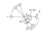
まずX線CT撮影における拡大率(倍率)について説明する。いまX線発生器1の位置(厳密にはX線発生器1におけるX線ビームの焦点の位置)をF、X線検出器2の位置(厳密にはX線検出器2におけるX線検出面の位置)をS、旋回機構の機構上の旋回軸3aの位置をB、被写体Oの位置(厳密には被写体Oの関心領域の中心の位置)をCとする。この場合、図1で(c)に示すように、旋回機構の機構上の旋回軸3aの位置Bと被写体Oの関心領域の中心の位置Cが同じであれば、被写体OがX線検出器2の撮像面に映る拡大率(倍率)は、X線発生器1とX線検出器2の距離FSとX線発生器上と機構上の旋回軸3aの距離FB(図1の(c)の場合、FB=X線発生器1と被写体Oの距離FC)を用いて表現すると、FS/FB(=FS/FC)である。First, an enlargement ratio (magnification) in X-ray CT imaging will be described. Now, the position of the X-ray generator 1 (strictly speaking, the position of the focal point of the X-ray beam in the X-ray generator 1) is F, and the position of the X-ray detector 2 (strictly, the X-ray detection surface in the X-ray detector 2). the position) S, position B of the
ここで、X線発生器1と被写体Oとの距離FCおよび/または被写体OとX線検出器2との距離CSを変えることにより拡大率を変えることができる。たとえば、図1で(a)に示すように、旋回機構の機構上の旋回軸3aに対して相対的に被写体Oの位置CをX線検出器2の側に移動すると、拡大率が小さくでき、大きい領域が撮影できる。この場合、撮影に先立って、被写体OをX線検出器2に相対的にX線検出器2の方向に距離α(>0)だけ移動する。次に、撮影時には、図2について後述するように、旋回手段3を旋回させると共に、旋回機構の旋回中心すなわち機構上の旋回軸3aを被写体Oの関心領域の中心(図1の(a)で回転中心である位置)を中心とする半径αの円周上を移動させるか、または、図3について後述するように、被写体Oを、旋回機構の旋回中心を中心とする半径αの円周上を移動させる。機構上の旋回中心は旋回機構の機構上の旋回軸3aであるが、被写体OがX線検出器2に映る拡大率はFS/(FB+α)(=FS/FC)である。 Here, the enlargement ratio can be changed by changing the distance FC between the
一方、図1で(b)に示すように、旋回機構の機構上の旋回軸3aに対して相対的に被写体Oの位置CをX線発生器1の側に移動すると、拡大率が大きくでき、小さい領域が撮影できる。この場合、撮影に先立って、被写体OをX線発生器1の方向に距離αだけ移動する。次に、撮影時には、図2について後述するように、旋回手段を旋回させるとともに、旋回機構の旋回中心すなわち機構上の旋回軸3aを被写体Oの関心領域の中心を中心とする半径αの円周上を移動させるか、または、被写体Oを、旋回機構の旋回中心を中心とする半径αの円周上を移動させる。この場合、機構上の回転中心は旋回機構の機構上の旋回軸3aであるが、被写体がX線検出器2に映る拡大率はFS/(FB−α)(=FS/FC)である。 On the other hand, as shown in FIG. 1B, if the position C of the subject O is moved toward the
ここで、図1の(a)と(b)の場合、旋回機構の機構上の旋回軸3aと被写体Oの関心領域の中心が異なるので、旋回機構の機構上の旋回軸3aまたは被写体Oの位置は、旋回機構が機構上の旋回軸3aの周りで旋回手段3を旋回させるときに、旋回機構の回転角度に従って円運動させねばならない。すなわち、この円運動が実現できればCT撮影における拡大率を可変にできる。このため、旋回機構全体を旋回機構の回転角度に従って円運動をさせればよい。これにより、X線発生器1、被写体O及びX線検出器2の相対的位置関係を一定に保つことができる。そのようなCT撮影では、以下のような効果がある。相対的位置関係が固定されたX線発生器1とX線検出器2を用いて、視野(関心領域の拡大率)を容易に可変にできる。特に、検出面域の広さが限られたX線検出器2を用いる場合に、ある拡大率では関心領域が大きすぎて検出面域に入りきらず、関心領域全域の撮影ができない場合に、拡大率を下げて関心領域全域が検出面域に収まるように撮影することができる。また、旋回手段に対してX線検出器2を移動させる機構や、旋回手段に対してX線発生器1を移動させる機構を用いることなく、拡大率変更が可能である。また、かりに旋回手段を旋回軸周りに旋回させた場合に、機械的不具合で軸ぶれが生じた場合でも、機構上の旋回軸と異なる撮影上の回転中心が設定されることより、容易に軸ぶれを補正できる。 Here, in the cases of FIGS. 1A and 1B, the center of the region of interest of the subject O is different from the
このため、第1のX線CT撮影装置では、旋回機構の機構上の旋回軸3aを機構上の旋回軸3aに交差する2次元の方向に移動させる、後に詳述する旋回軸移動機構31を設ける。図2は、この制御の状況を示す。旋回軸移動機構31は、機構上の旋回軸3aを移動するが、それと同時に、旋回手段3は、移動中の機構上の旋回軸3aの周りでX線発生器1及びX線検出器2を旋回する。この2種の移動は、被写体Oの関心領域の中心3XとX線発生器1及びX線検出器2との距離を常に一定に保つように同期される。この2種の動きの連動による合成運動において、被写体Oの関心領域の中心3Xが撮影上の回転中心となり、X線発生器1及びX線検出器2は、被写体Oの関心領域の中心3Xの周りで中心3Xとの距離を常に一定に保って旋回される。こうして、旋回機構の機構上の旋回軸3aと被写体Oの関心領域の中心とが位置的に異なっても、旋回機構による旋回手段の旋回及び旋回軸移動機構による機構上の旋回軸の移動を連動させる合成運動により、機構上の旋回軸3aとは異なる撮影上の回転中心3xが常に前記被写体の関心領域の中心3Xに設定され、旋回手段3は、常に被写体Oの関心領域の中心3Xの周りに旋回する。 For this reason, in the first X-ray CT imaging apparatus, a swivel
ここで、機構上の旋回軸3aとは異なる「撮影上の回転中心3x」とは、機構上の旋回軸とは独立した、機構上の旋回軸3a自体を移動可能な旋回軸移動機構の存在により実現される撮影上の回転中心という意味であって、機構上の旋回軸3aと撮影上の回転中心3xとが、位置的に一致する場合も含まれる。X線発生器1とX線検出器2を対向して保持する旋回手段3が旋回機構により旋回されるとともに、その回転角度に対応して、旋回機構の中心(移動された回転中心に対応する機構上の旋回軸3a)を関心領域の中心3X(初めの回転中心にあった位置に対応する)に対して相対的に回転して、X線発生器1、被写体O及びX線検出器2の相対的位置関係を一定に保つ。なお、図2と後述の図3は、拡大率を小さくする場合を示しているが、拡大率を大きくする場合は、関心領域の中心3Xは、X線発生器1側に位置させる。 Here, the “photographing
また、被写体Oを旋回機構の回転角度に従って円運動をさせる第2のX線CT撮影装置では、X線発生器1とX線検出器2との間にあって被写体Oを保持する被写体保持機構に、旋回機構の機構上の旋回軸3aに交差する2次元の方向に移動させる、後に詳述する被写体移動機構5を備える。図3は、この制御の状況を示す。旋回機構の機構上の旋回軸3aと被写体の関心領域の中心3Xが位置的に異なっても、制御部により、旋回機構による旋回手段3の旋回及び被写体移動機構5による被写体Oの回動を、同期して同時に連動させる合成運動により、被写体の関心領域の中心3XとX線発生器1及びX線検出器2との距離を常に一定に保つ。つまり、機構上の旋回軸3aとは異なる撮影上の回転中心3xが設定され、常に被写体Oの関心領域の中心3Xに位置して旋回手段3が旋回するように保つ。 In the second X-ray CT imaging apparatus that causes the subject O to move circularly according to the rotation angle of the turning mechanism, the subject holding mechanism that holds the subject O between the
ここで、機構上の旋回軸3aとは異なる「撮影上の回転中心3x」とは、機構上の旋回軸とは独立した、被写体を回動可能な被写体移動機構の存在により実現される撮影上の回転中心という意味であって、機構上の旋回軸3aと撮影上の回転中心3xとが、位置的に一致する場合も含まれる。旋回手段が旋回機構により旋回されるとともに、その回転角度に対応して、被写体の関心領域の中心3Xを旋回機構の中心(機構上の旋回軸3a)に対して相対的に回転して、X線発生器1、被写体及びX線検出器2の相対的位置関係を一定に保つ。 Here, the “photographing
以上の図2と図3に示した実施形態を以下でさらに詳しく説明する。
図4の(a)は、図2の第1のX線CT撮影装置を模式的に示す。旋回手段3は、本実施形態においては、X線発生器1とX線検出器(2次元X線イメージセンサ)2とを被写体Oを挟んで対向した状態で配置した旋回アームである。旋回アームを用いることにより、機械的に簡易な構造で機構上の旋回軸3aを設けることができる。旋回手段3は、後述する回転制御モータ33により機構上の旋回軸3aを中心に旋回する。旋回軸3aは鉛直方向にある。機構上の旋回軸3aと回転制御モータ33は旋回機構を構成する要素の一部である。XYテーブル31は、旋回手段3の機構上の旋回軸3aを機構上の旋回軸3aに交差する2次元の方向に、ここでは旋回軸3aに垂直な平面で、移動させる旋回軸移動機構である。被写体移動機構であるXYテーブルは、交差する2つの方向にそれぞれ移動可能な移動手段を備えるので、被写体Oの2次元移動制御が容易である。被写体Oは、固定されており、中心部およびその付近に領域Bを、それ以外の部分に領域Aを有する。The embodiment shown in FIGS. 2 and 3 will be described in more detail below.
FIG. 4A schematically shows the first X-ray CT imaging apparatus of FIG. In this embodiment, the swivel means 3 is a swivel arm in which the
図4の(b)は、図3の第2のX線CT撮影装置を模式的に示す。旋回手段3は、X線発生器1とX線検出器(2次元X線イメージセンサ)2とを被写体Oを挟んで対向した状態で配置した旋回アームである。旋回手段3は、図4の(a)の例と同様、機構上の旋回軸3aを中心に旋回する。被写体Oは、中心部及びその付近に領域Bを、それ以外の部分に領域Aを有し、図示しない被写体位置移動手段5により前後左右上下方向に移動される。被写体位置移動手段5は、旋回機構の機構上の旋回軸3aに交差する2次元の方向に、ここでは旋回軸3aに垂直な平面で被写体Oを移動させる被写体移動機構である。 FIG. 4B schematically shows the second X-ray CT imaging apparatus of FIG. The swivel means 3 is a swivel arm in which the
上述の図4の(a)に示した旋回軸移動機構は、機構上の旋回軸3aに交差する2次元の方向に移動させる移動機構であり、上述の図4の(b)に示した被写体移動機構は、被写体Oを旋回軸3aに交差する2次元の方向に移動させる移動機構である。旋回軸移動機構と被写体移動機構のいずれか一方を備え、旋回軸3aと被写体Oのいずれか一方を移動させてもよいが、旋回軸移動機構と被写体移動機構の双方を備え、双方を同時に移動させてもよい。 The turning axis moving mechanism shown in FIG. 4 (a) is a moving mechanism that moves in a two-dimensional direction intersecting the turning
図5の(a)、(b)は、図4の(a)における実施形態を平面に表した様子を示す。図5の(a)は、被写体Oを旋回機構の機構上の旋回軸3aからX線発生器1の方向に距離αだけ相対的に移動して撮影する例であり、図5の(b)は、被写体Oを旋回機構の機構上の旋回軸3aからX線検出器2の方向に距離αだけ相対的に移動して撮影する例である。旋回手段3が前述の旋回機構により旋回されるとともに、その回転角度に対応して旋回機構の機構上の旋回軸3aが、同期して連動され、旋回手段3と機構上の旋回軸3aの合成運動により、関心領域の中心に対して相対的に回転移動され、X線発生器1、被写体O及びX線検出器2の相対的位置関係を一定に保ち、前記旋回機構の機構上の旋回軸3aとは異なる前記旋回機構の撮影上の回転中心3aが常に前記被写体の関心領域の中心3Xに位置して前記旋回手段3が旋回するようにして撮影する。 FIGS. 5A and 5B show a state in which the embodiment in FIG. FIG. 5A shows an example in which the subject O is imaged while moving relatively by a distance α in the direction of the
図5(a)においては、機構上の旋回軸3aが、機構上の旋回軸3aからX線発生器1の方向に距離αだけ離れた関心領域の中心3Xに対して、半径αの円を描くように位置LC1→位置LC2→位置LC3のように相対的に回転移動される。被写体OはX線検出器2から距離α分遠ざかり、X線検出器2は領域Bの部分のみ検出し、この領域Bの画像再構成ができる。領域AはX線検出器2の検出可能な範囲外である。また、図5の(b)においては、機構上の旋回軸3aが、機構上の旋回軸3aからX線検出器2の方向に距離αだけ離れた関心領域の中に対して、半径αの円を描くように位置LC1’→位置LC2′→位置LC3′のように相対的に回転移動される。被写体OはX線検出器2から距離α分近づき、X線検出器2は領域Bの部分のみならず、領域Aの部分も完全に検出する。この領域Aと領域Bの双方の領域の画像再構成ができる。図5の(a)、(b)により理解できるように、X線発生器1とX線検出器2との距離に対する、X線発生器1と撮影上の回転中心3Xとの距離および/またはX線検出器1と撮影上の回転中心3Xとの距離を相対的に変更可能とすることにより拡大率が変更可能である。 In FIG. 5 (a), the turning
被写体を動かさずに、旋回手段のみを移動させて、ある拡大率用の設定から、所望の拡大率用に変更した撮影をすることも可能である。すなわち、たとえば、最初は機構上の旋回軸3aを関心領域の中心に一致させて撮影し、次に拡大率を上げたい場合は、被写体はそのまま動かさず、旋回軸3aを、図5の(a)の位置LC1で示される位置まで移動させ、位置LC1を初期位置として、上述したように、撮影領域の中心3Xに対して、旋回軸3aを、半径αの円を描くように位置LC1→位置LC2→位置LC3のように相対的に回転移動して撮影する。その後、逆に拡大率を下げたい場合は、被写体はそのまま動かさず、旋回軸3aを、図5の(b)の位置LC1´で示される位置まで移動させ、位置LC1´を初期位置として、上述したように、撮影領域の中心3Xに対して、旋回軸3aを、半径αの円を描くように位置LC1´→位置LC2´→位置LC3´のように相対的に回転移動して撮影する。このように、被写体を動かさずに、自在に拡大率を変更した撮影ができる。 It is also possible to move the turning means without moving the subject, and take a picture changed from a setting for a certain enlargement ratio to a desired enlargement ratio. That is, for example, when photographing is first performed with the
図6の(a)、(b)は、図4の(b)における実施形態を平面に表した様子を示す。図6の(a)は、被写体Oを旋回機構の機構上の旋回軸からX線発生器1の方向に距離αだけ相対的に移動して撮影する例であり、図6の(b)は、被写体Oを旋回機構の機構上の旋回軸3aからX線検出器2の方向に距離αだけ相対的に移動して撮影する例である。旋回手段3が前述の旋回機構の機構上の旋回軸3aを中心として旋回されるとともに、その回転角度に対応して、被写体Oが被写体位置移動機構5により同期して連動され、旋回手段3と被写体Oとの合成運動により、X線発生器1、被写体及びX線検出器2の相対的位置関係を一定に保つ。こうして、旋回機構の機構上の旋回軸3aとは異なる旋回機構の撮影上の回転中心3Xが常に前記被写体の関心領域の中心3Xに位置して、旋回機構が旋回する。 FIGS. 6A and 6B show a state in which the embodiment in FIG. FIG. 6A shows an example in which the subject O is imaged by moving relatively from the turning axis on the turning mechanism in the direction of the
図6の(a)においては、機構上の旋回軸3aからX線発生器1の方向に距離αだけ離れた関心領域の中心3Xが、機構上の旋回軸3aに対して、半径αの円を描くように位置LC10→位置LC20→位置LC30のように相対的に回動される。被写体Oは、被写体位置移動機構5により位置的には回動するが、その向きを変えずに撮影される。例えば、被写体が人間の頭部であれば、その頭部は一定の方角を向いたままで位置LC10→位置LC20→位置LC30のように相対的に回動される。被写体OはX線検出器2から距離α分遠ざかり、X線検出器2は領域Bの部分のみ検出し、この領域Bの画像再構成ができる。領域AはX線検出器2の検出可能な範囲外である。 In FIG. 6A, the
また、図6の(b)においては、機構上の旋回軸3aからX線検出器2の方向に距離αだけ離れた関心領域の中心3Xが、機構上の旋回軸3aに対して、半径αの円を描くように位置LC10’→位置LC20′→位置LC30′のように相対的に回動される。被写体OはX線検出器2から距離α分近づき、X線検出器2は領域Bの部分のみならず、領域Aも完全に検出する。この領域Aと領域Bの双方の領域の画像再構成ができる。 In FIG. 6B, the
図6の(a)、(b)の場合、撮影上の回転中心3Xが、常に関心領域の中心3Xに存在するように制御される。すなわち、第1のX線CT撮影装置と、第2のX線CT撮影装置は、X線発生器1とX線検出器2とが被写体Oを挟んで対向して配置されている旋回手段3を備え、旋回手段3を、X線発生器1から照射されるX線に垂直な方向の機構上の旋回軸3aの周りで旋回させる旋回機構と、この旋回機構の機構上の旋回軸3aおよび/または前記被写体Oを機構上の旋回軸3aに垂直な平面で移動させる移動機構を備える。この移動機構が、第1のX線CT撮影装置の場合は旋回軸移動機構31であり、第2のX線CT撮影装置の場合は被写体移動機構5である。後述の制御部7は、前記旋回機構による旋回手段3の旋回と、前記移動機構による旋回機構の機構上の旋回軸3aおよび/または被写体Oの移動とを、同期して同時に連動させる合成運動により、機構上の旋回軸3aとは異なる撮影上の回転中心3xを設定し、被写体Oの関心領域の中心に対するX線発生器1とX線検出器2の距離を常に一定に保つように制御する。 In the case of FIGS. 6A and 6B, the
こうして拡大率の変更が容易に行えるので、目的に応じて拡大率の使い分けが可能になる。たとえば歯科用のCT撮影装置において、全顎のボリュームレンダリング画像が必要な場合には、拡大率を下げて大きな領域を撮影できる。また、歯内療法に使用する詳細な数歯の画像が必要な場合には、拡大率を上げて小さな領域を詳細に撮影できる。 Since the enlargement ratio can be easily changed in this way, the enlargement ratio can be properly used according to the purpose. For example, in a dental CT imaging apparatus, when a volume rendering image of the entire jaw is required, a large area can be imaged with the enlargement ratio lowered. In addition, when a detailed image of several teeth used for endodontic treatment is necessary, a small region can be photographed in detail by increasing the magnification.
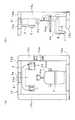
次に、第1のX線CT撮影装置の1例をさらに具体的に説明する。図7と図8は、前述の図2、図4の(a)、図5の(a)、(b)に示される第1のX線CT撮影装置の具体例を示す。門型の非常に剛性の高い構造体である主フレーム10は全体の支持体である。この主フレーム10は、旋回手段3を吊り下げ回転可能に支持する上フレーム10a、この上フレーム10aの基端部を固定保持している1対の横ビーム10b、この横ビーム10bを支えている一対の縦ビーム10C、当該縦ビーム10Cが固定載置され、この装置全体の基礎となっているベース10dから構成されている。被写体位置移動手段5は、ベース10dの上にあり、被写体保持手段4である椅子4bを載置している。操作パネル10eは、主フレーム10の一方の縦ビーム10Cの表面に設けられている。 Next, an example of the first X-ray CT imaging apparatus will be described more specifically. FIGS. 7 and 8 show specific examples of the first X-ray CT imaging apparatus shown in FIGS. 2 and 4 (a) and FIGS. 5 (a) and 5 (b). The
旋回手段3は、X線コーンビームを発生するX線発生器1とX線検出器(2次元X線イメージセンサ)2とを対向した状態で配置したU字状の旋回アームである。CT撮影の際は、旋回手段3は、被写体の周りを旋回され、旋回中に、X線発生器1が発生したコーンビームX線は、被写体に照射され、被写体を透過したX線はX線検出器2により投影データとして検出される。投影データから被写体の3次元画像が再構成される。 The swivel means 3 is a U-shaped swivel arm in which an
XYテーブル31は、上フレーム10aに固定されていて、旋回手段3を旋回可能に支持している。XYテーブル31は、鉛直方向にある旋回軸3aを旋回軸3aに垂直な平面で移動させる旋回軸移動機構の1例である。XYテーブル31は、後で説明するように、水平面上で互いに直交する方向に移動可能であり、第1の方向であるY方向に移動するYテーブルとYテーブルに支持されてY方向と直交する第2の方向であるX方向に移動するXテーブルからなる。(X方向は、図7の(a)の正面に向かって左右方向であり、Y方向はX方向と直交する方向である。)さらに、XYテーブル31のために、XYテーブル31をX方向に移動させるX軸制御モータ31aと、Y方向に移動させるY軸制御モータ31bと、XYテーブル31に垂直な方向に直交する方向(図7の(a)の正面に向かって上下方向)に旋回手段3を移動させる昇降制御モータ32と、旋回手段3を旋回させる回転制御モータ33とが設けられている。回転制御モータ33は、旋回手段3の中空部3bの中に設置される機構上の旋回軸(旋回中心)3a(以下、機構上の旋回軸3aまたは単に旋回軸3aと記載する)を回動する。X軸制御モータ31aとY軸制御モータ31bを制御することによって、旋回手段3の旋回軸3aをXY方向に移動でき、また、昇降制御モータ32を駆動することによって旋回手段3が上下に昇降する。撮影時には回転制御モータ33を等速度で駆動させて旋回手段3を被写体の周りに旋回する。なお、この実施の形態ではXYテーブル31を用いて第1の方向(たとえばX方向)と第1の方向と直交する第2の方向(たとえばY方向)に旋回軸3aを移動しているが、より一般的には、直交でなくとも、第1の方向と第1の方向と異なる第2の方向に旋回軸3aを移動するようにしてもよい。また、旋回軸3aは、本実施形態では鉛直方向に配置されているが、水平方向に配置して、たとえば患者が水平に仰臥して撮影される構成にしてもよい。 The XY table 31 is fixed to the upper frame 10a, and supports the turning means 3 so as to be turnable. The XY table 31 is an example of a turning axis moving mechanism that moves the turning
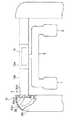
図9は、旋回アーム3の位置と旋回の制御に関連する部分を示す。上フレーム10aは、前後方向(Y方向)に移動するテーブル(Yテーブル)54Y、Yテーブルに支持されて横方向(X)方向に移動するテーブル(Xテーブル)54X、YテーブルをY方向に移動させるY方向のY軸制御モータ31a、Yテーブルに対してXテーブルをX方向に移動させるX軸制御モータ31b(図示しない)、Xテーブル54Xと旋回アーム3を連結する旋回軸3aの軸心である垂直軸62を中心として旋回アーム3を旋回させる回転制御モータ33を備えている。旋回軸3aには、ベアリング3Cが取り付けられており、回転制御モータ33は旋回アーム3の内部に固定され、ベルト34によりベアリング3Cに回動力を伝達して、旋回アーム3を旋回させる。旋回軸3a、ベアリング3C、ベルト34および回転制御モータ33は、旋回手段3を旋回する旋回機構の1例である。3つの制御モータを予め決められたプログラムに従って駆動することで、旋回アーム3を旋回しながら、XYテーブルを前後(Y方向)および左右(X方向)に移動できる。 FIG. 9 shows the position of the
図10は、旋回アーム3の昇降制御に関連する部分の一例である。横ビーム10bは縦ビーム10cに対して昇降変位する構成になっている。横ビーム10bの端からは突部10b1が突出し、縦ビーム10cに穿設された孔部10c1を貫通している。突部10b1には、図示しないねじ孔が穿設されていて、縦ビーム10cに固定された昇降制御モータ32のねじ軸32aが突部10b1の当該ねじ孔に螺合している。ねじ軸32aは、前述のX方向とY方向に直交する方向を軸方向としている。これらの、突部10b1、孔部10c1、ねじ孔、昇降制御モータ32、ねじ軸32aの構成は、横ビーム10bの両端および一対の縦ビーム10cの双方に設けられる。昇降制御モータ32によりねじ軸32aが回動され、突部10b1を昇降変位させることで、横ビーム10b全体が昇降し、旋回アームも昇降される。 FIG. 10 is an example of a portion related to the lifting control of the
図11は図9の旋回アーム3の位置と旋回の制御に関連する部分を平面視した図である。前後方向(Y方向)に移動するテーブル(Yテーブル)54Y、Yテーブルに支持されて横方向(X)方向に移動するテーブル(Xテーブル)54X、YテーブルをY方向に移動させるY方向のY軸制御モータ31a、Yテーブルに対してXテーブルをX方向に移動させるX軸制御モータ31bの配置が理解できる。テーブル(Xテーブル)54Xは、前記旋回機構の前記旋回軸を第1の方向に移動可能な第1移動手段をなし、テーブル(Yテーブル)54Yは前記第1の方向と異なる第2の方向に移動可能な第2移動手段をなす。なお、上述の実施例では制御のための座標計算の便宜上、X方向とY方向が直交するが、特に直交でなくとも、2次元制御ができれば、任意の角度で交差させて構わない。 FIG. 11 is a plan view of a portion related to the position of the
次に、制御部7によるCT撮影制御のうち、倍率可変のための旋回制御処理を説明する。旋回中心を円運動させる場合について説明すると、操作者が、操作部11の拡大率変更手段12により拡大率を指示すると、図12に示すような制御が起動される。まず、拡大率に対応する旋回中心の移動距離を計算し(S10)、X軸制御モータ31bとY軸制御モータ31aを作動して、旋回軸3aをその距離だけ移動させる(S12)。さらに、旋回中心の円運動軌道を計算する(S14)。撮影時には、回転制御モータ22を作動させて、旋回アーム3を旋回させると共に、X軸制御モータ31bとY軸制御モータ31aを作動させて、旋回軸3aを被写体Oの中心の周りの半径αの円周上を移動させる。(S16)。すなわち、このCT撮影制御では、拡大率に対応して、回転制御モータ22の旋回条件と、X軸制御モータ31bとY軸制御モータ31aの移動の軌跡を計算し、回転制御モータ22と、X軸制御モータ31bとY軸制御モータ31aを制御して、旋回及び移動の合成運動により、常に被写体Oの関心領域の中心を、旋回軸3aとは異なる撮影上の回転中心3xとして、旋回アーム3を旋回させる。 Next, turning control processing for changing the magnification in the CT imaging control by the control unit 7 will be described. The case where the turning center is caused to perform a circular motion will be described. When the operator instructs the enlargement ratio using the enlargement ratio changing means 12 of the
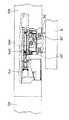
なお、図9に示す実施形態では、回転制御モータ33を旋回アーム側に配置したが、図13に示すように上フレーム10aの同じハウジング内に回転制御モータ33’を設けるようにしてもよい。図13に示す実施形態では、図9の実施形態と異なり、旋回アーム3側に回転制御モータ33が備えられておらず、回転制御モータ33′が上フレーム10aのハウジング内のテーブル(Xテーブル)54Xに固定され、当該テーブル54Xにベアリング3C’を介して回動可能に軸支される旋回アーム3の旋回軸3a’に回動力を伝達している。このようにXYテーブル(旋回軸移動機構)が回転制御モータ33′(旋回機構)と同じハウジング内に設けられるので、2次元的に広いスペースを占めることが多い旋回軸移動機構のいずれかの適宜な空間を有効利用して旋回機構を設けることができる。また、同じハウジング内に設けるので、たとえば旋回機構を旋回手段側に設ける必要がなくなり、旋回手段の構造を簡易化できる。 In the embodiment shown in FIG. 9, the
倍率を変えるため、先に説明したように旋回中心の位置を制御する場合、例えば、撮影に先立って、被写体をX線検出器2に相対的にX線検出器2の方向に距離α(>0)だけ移動する場合、X軸制御モータ31bとY軸制御モータ31aを作動させて、距離αに相当する距離だけXテーブル54XとYテーブル54Yを移動させてX線検出器2を被写体Oに近づける。撮影時には、回転制御モータ33を作動させて、旋回アーム3を旋回させると共に、X軸制御モータ31bとY軸制御モータ31aを作動させて旋回軸3aを被写体Oの中心の周りの半径αの円周上を移動させる。撮影の原理は、図5の(a)、(b)について説明したとおりである。 In order to change the magnification, when the position of the turning center is controlled as described above, for example, prior to imaging, the subject is moved relative to the
次に、第2のX線CT撮影装置の1例をさらに具体的に説明する。図14と図15は、前述の図3、図4の(b)、図6の(a)、(b)に示される第2のX線CT撮影装置の具体例を示す。基本的構造は、図7と図8に示す前述の第1のX線CT撮影装置と同様であるが、旋回軸移動機構である、XYテーブル31が存在しない代わりに、被写体移動機構であるX方向とY方向の2次元に移動する被写体位置移動手段5が存在する点が異なっている。被写体位置移動手段5が主フレーム10のベース10dの上に設けられ、その上に、被写体(患者)を座位で保持する椅子4bが載置される。被写体保持機構4は、椅子4bと、この椅子4bの背部に設けられた頭部固定手段4aとを備えている。被写体保持機構は上述の椅子と頭部固定手段に限られず、患者の顎を置くチンレスト、患者の耳を挟持するイヤロッドその他、被写体が保持できればいずれでも構わない。被写体位置移動手段5は、椅子4bをX,Y,Z方向に、つまり、前後左右上下方向に移動させることができる。被写体位置移動手段5は、椅子4bをX方向に移動させるX軸制御モータ51、Y方向に移動させるY軸制御モータ52、図14の(a)の正面から向かって上下方向に移動させる上下移動手段であるZ軸制御モータ53を備えている。これらモータ51〜53で駆動されるX軸、Y軸、Z軸直線移動テーブル(図示しない)は、それぞれ周知のクロスローラガイドや、通常のベアリングとガイドを組み合わせたものなどで構成され、正確に直線移動ができるものである。また、モータ51〜53による、これらのX軸、Y軸,Z軸直線移動テーブルの移動は、ラックとピニオン方式や、ボールネジ方式や、通常のネジ軸を用いる方式などを適用できるが、正確に位置決めできるものが望ましい。被写体位置移動手段5は、図4の(b)で説明した、旋回機構の機構上の旋回軸3aに垂直な平面で被写体を移動させる被写体移動機構の例である。なお、この実施の形態では被写体位置移動手段5は、第1の方向(たとえばX方向)と第1の方向と直交する第2の方向(たとえばY方向)に椅子4bを移動しているが、より一般的には、直交でなくとも、第1の方向と第1の方向と異なる第2の方向に椅子4bを移動するようにしてもよい。 Next, an example of the second X-ray CT imaging apparatus will be described more specifically. FIGS. 14 and 15 show specific examples of the second X-ray CT imaging apparatus shown in FIGS. 3 and 4 (b) and FIGS. 6 (a) and 6 (b). The basic structure is the same as that of the first X-ray CT imaging apparatus shown in FIGS. 7 and 8 except that the XY table 31 that is the pivot axis moving mechanism does not exist and the X that is the subject moving mechanism. The difference is that there is a subject position moving means 5 that moves two-dimensionally in the Y direction. The subject position moving means 5 is provided on the
倍率を変えるため、先に説明したように被写体Oの位置を制御する場合、例えば、撮影に先立って、被写体OをX線検出器2に相対的にX線検出器2の方向に距離αだけ移動する場合、X軸制御モータ51とY軸制御モータ52を作動させて、距離αに相当する距離だけ椅子4bをX方向とY方向に移動させて被写体OをX線検出器2に近づける。撮影時には、回転制御モータ22を作動させて、旋回アーム3を旋回させると共に、X軸制御モータ51とY軸制御モータ52を作動させて、椅子4bを旋回軸3aの周りの半径αの円周上を移動させる。撮影の原理は、図6の(a)、(b)について説明したとおりである。 When the position of the subject O is controlled as described above in order to change the magnification, for example, prior to imaging, the subject O is moved relative to the
次に、X線CT撮影装置のCT撮影制御について説明する。図8に示すように、第1のX線CT撮影装置であるX線CT撮影装置20は、コンピュータ本体を含む制御装置(制御部)7を備える。制御装置7は、CPU、記憶装置および入出力インタフェースを備え、演算プロセッサを含む演算処理手段6、キーボード8、マウス9、液晶画面等の表示モニター13、操作部11(操作パネル10eを含む)等に接続される。操作部11は、操作者が拡大率を入力するための拡大率変更手段12を含む。制御装置7は、X線発生器1とX線検出器2に接続され、また、上述のXYテーブル31のためのX軸制御モータ31a、Y軸制御モータ31b、昇降制御モータ32および回転制御モータ33の駆動を制御する。記憶装置には、CT撮影制御のための制御プログラムや、投影データから3次元CTデータを演算する演算処理プログラムを含む。 Next, CT imaging control of the X-ray CT imaging apparatus will be described. As shown in FIG. 8, an X-ray CT imaging apparatus 20 that is a first X-ray CT imaging apparatus includes a control device (control unit) 7 including a computer main body. The control device 7 includes a CPU, a storage device, and an input / output interface, and includes an arithmetic processing means 6 including an arithmetic processor, a keyboard 8, a mouse 9, a
図15に示すように、第2のX線CT撮影装置であるX線CT撮影装置20は、コンピュータ本体を含む制御装置(制御部)7を備える。制御装置7は、CPU、記憶装置および入出力インタフェースを備え、演算プロセッサを含む演算処理手段6、キーボード8、マウス9、液晶画面等の表示モニター13、操作部11(操作パネル10eを含む)等に接続される。操作部11は、操作者が拡大率を入力するための拡大率変更手段12を含む。制御装置7は、X線発生器1とX線検出器2に接続され、また、上述の被写体位置移動手段5のためのX軸制御モータ51、Y軸制御モータ52およびZ軸制御モータ53の駆動を制御する。記憶装置には、CT撮影制御のための制御プログラムや、投影データから3次元CTデータを演算する演算処理プログラムを含む。第2のX線CT撮影装置は、図15に示すように、さらに上述の第1のX線CT撮影装置で用いられるXYテーブル31を備えていてもよい。 As shown in FIG. 15, an X-ray CT imaging apparatus 20 that is a second X-ray CT imaging apparatus includes a control device (control unit) 7 including a computer main body. The control device 7 includes a CPU, a storage device, and an input / output interface, and includes an arithmetic processing means 6 including an arithmetic processor, a keyboard 8, a mouse 9, a
図15に示す第2のX線CT撮影装置において、被写体Oを円運動させる場合も、その倍率可変のための旋回制御処理は、図12の第1のX線CT撮影装置におけると同様であるので、図12を用いて説明するが、移動対象が異なることに対応して、処理の内容が異なる。すなわち、ステップS10では、拡大率に対応する椅子4bと被写体Oの移動距離を計算し、ステップS12でX軸制御モータ51とY軸制御モータ52を作動して、椅子4bをその距離だけ移動させる。さらに、ステップS14で、椅子4bの円運動軌道を計算する。撮影時にはステップ16で、回転制御モータ22を作動させて、旋回アーム3を旋回させると共に、X軸制御モータ51とY軸制御モータ52を作動させて、椅子4bを旋回中心の周りの半径αの円周上を移動させる。 In the second X-ray CT imaging apparatus shown in FIG. 15, the turning control process for changing the magnification is the same as that in the first X-ray CT imaging apparatus of FIG. Therefore, although it demonstrates using FIG. 12, the content of a process differs corresponding to a movement object differing. That is, in step S10, the moving distance between the chair 4b and the subject O corresponding to the enlargement ratio is calculated, and in step S12, the
上述の第1のX線CT撮影装置の実施の形態では、旋回機構の機構上の旋回軸3aを旋回軸に垂直な平面で移動させる旋回軸移動機構としてXYテーブル31が用いられた。しかし、XYテーブルの代わりに他の旋回軸移動機構を用いてもよい。たとえば、図16に図式的に示すように、相互に回動自在に結合された結合部材である複数のリンク部材で、旋回アーム3の位置を変えてもよい。図16の例では、直列に接続される2本のリンク部材80,81が用いられる。第1のリンク部材80は、上フレーム10aにシャフト82で回動自在に取り付けられる。第1のリンク部材80と第2のリンク部材81はシャフト83で回動自在に連結され、さらに、第2のリンク部材81は旋回アーム3の旋回軸3aの軸受けに回動自在に結合される。シャフト82、83や旋回軸3aは、それぞれに対して配置された駆動モータ84,85,86により回動される。制御部7は、駆動モータ84〜86を制御して、旋回軸3aの位置を旋回軸3aに垂直な2次元平面内で移動できる。In the embodiment of the first X-ray CT imaging apparatus described above, the XY table 31 is used as a turning axis moving mechanism that moves the turning
また、図17には旋回軸移動機構の別の変形例を図式的に示す。この例では、結合部材である伸縮部材90を用いる。伸縮部材90の1端は上フレーム10aにシャフト91を介して回動自在に取り付けられ、伸縮部材90の他端は旋回アーム3の旋回軸3aの軸受けに回動自在に結合される。伸縮部材90は、その長手方向に伸縮自在であり、また、シャフト91や旋回軸3aは、それぞれに対して設けられた駆動モータ92,93により回動される。制御部7は、伸縮部材90や駆動モータ92,93を制御して、旋回軸3aの位置を旋回軸3aに垂直な2次元平面内で移動できる。図16や図17に示されたような旋回軸移動機構は、旋回機構の旋回軸の軸受けに結合された1つ又は複数の直列に接続された結合部材により構成されるので、簡易な構造で旋回軸の2次元移動制御が可能である。 FIG. 17 schematically shows another modification of the turning axis moving mechanism. In this example, the
上述の実施形態においては、基本的にはX線CT撮影装置が、旋回軸移動機構または被写体移動機構のいずれか一方を備えるが、図15の説明にて述べたように、1つのX線CT撮影装置が、旋回軸移動機構と被写体移動機構の双方を備えるようにすれば、さらに制御の組合せの幅が拡がる。その場合、旋回機構による旋回手段の旋回及び旋回軸移動機構による機構上の旋回軸の移動とを同期して連動させる合成運動による撮影か、旋回機構による旋回手段の旋回及び被写体移動機構による被写体の回動とを同期して連動させる合成運動による撮影かを選択できるようにしてもよい。さらに、旋回機構による旋回手段の旋回及び旋回軸移動機構による機構上の旋回軸の移動と、被写体移動機構による被写体の回動の3者を、同期して連動させる合成運動により、旋回機構の機構上の旋回軸とは異なる撮影上の回転中心が常に前記被写体の関心領域の中心に位置して前記旋回手段が旋回するようにして、X線発生器とX線検出器との距離に対する、X線発生器と撮影状の旋回軸との距離および/またはX線検出器と撮影上の回転中心との距離を相対的に変更可能とすることにより、拡大率を変更可能に制御することもできる。 In the above-described embodiment, the X-ray CT imaging apparatus basically includes either one of the pivot axis moving mechanism and the subject moving mechanism. However, as described with reference to FIG. If the photographing apparatus is provided with both the turning axis moving mechanism and the subject moving mechanism, the range of control combinations is further expanded. In that case, the shooting by the combined movement that synchronizes the turning of the turning means by the turning mechanism and the movement of the turning axis on the mechanism by the turning axis moving mechanism, or the turning of the turning means by the turning mechanism and the subject movement by the subject moving mechanism. It may be possible to select whether the image is shot by a combined motion that is synchronized with the rotation. Further, the mechanism of the turning mechanism is combined by a combined motion that synchronizes and synchronizes the turning of the turning means by the turning mechanism and the movement of the turning axis on the mechanism by the turning axis moving mechanism and the turning of the subject by the subject moving mechanism. An X-ray generator and an X-ray detector have a distance of X relative to the distance between the X-ray generator and the X-ray detector so that the rotation center on the imaging different from the upper rotation axis is always positioned at the center of the region of interest of the subject. By making it possible to relatively change the distance between the X-ray detector and the center of rotation on the radiography and / or the distance between the X-ray detector and the rotational axis on the radiography, the enlargement ratio can be controlled to be changeable. .
上述の旋回軸または被写体の移動のパターンは様々に考えられるが、そのうちのいくつかを例示する。
(1)X方向、Y方向、Z方向全てを旋回軸移動機構で制御
(2)X方向、Y方向、Z方向全てを被写体移動機構で制御
(3)X方向、Y方向については旋回軸移動機構で、Z方向については被写体移動機構で制御
(4)X方向、Y方向については被写体移動機構で、Z方向については旋回軸移動機構で制御
(5)X方向、Y方向について旋回軸移動機構と被写体移動機構と双方で同時に制御
(6)X方向、Y方向、Z方向全てを旋回軸移動機構と被写体移動機構と双方で同時に制御
上述の(5)と(6)のパターンによれば、旋回手段と被写体保持機構双方の変位量を特に小さく抑えられるという効果がある。There are various patterns of movement of the pivot axis or the subject described above, but some of them are exemplified.
(1) All the X, Y, and Z directions are controlled by the pivot movement mechanism. (2) All the X, Y, and Z directions are controlled by the subject movement mechanism. (3) The pivot movement is performed for the X and Y directions. In the mechanism, the Z direction is controlled by the subject moving mechanism (4) The X direction is controlled by the subject moving mechanism in the Y direction, and the Z direction is controlled by the swing axis moving mechanism (5) The swing axis moving mechanism in the X direction and the Y direction (6) All X direction, Y direction, and Z direction are controlled simultaneously by both the pivot axis moving mechanism and the subject moving mechanism. According to the patterns (5) and (6) described above, There is an effect that the amount of displacement of both the turning means and the subject holding mechanism can be suppressed particularly small.
なお、上述の実施の形態では、拡大率を変更可能としている。しかし、いうまでもなく、拡大率が一定の場合でも、旋回機構の旋回軸と撮影上の回転中心の位置を異ならせて、旋回手段3の旋回と、旋回軸3aおよび/または被写体Oの移動との連動による合成運動により、常に被写体の関心領域の中心を、前記旋回機構の旋回軸とは異なる撮影上の回転中心として前記旋回手段を旋回させるようにして、X線CT撮影を行える。 In the above-described embodiment, the enlargement ratio can be changed. Needless to say, however, even when the enlargement ratio is constant, the turning of the turning means 3 and the movement of the turning
また、旋回手段3は、上述のU字状の旋回アームでもよいが、たとえば患者を水平にして撮影する周知のガントリでもよく、X線発生器1とX線検出器2とを対向配置させつつ旋回できるものであれば、適宜の形状でよい。 The swivel means 3 may be the U-shaped swivel arm described above, but may be a well-known gantry that takes an image with the patient placed horizontally, for example, while the
また、本発明の出願人は、既に特開平10−225455で公開されている、CTモードとパノラマモードの切換が可能な構成のX線撮影装置を出願しているが、この特開平10−225455のX線撮影装置の構成に、さらに本発明の構成を付加することも可能である。すなわち、本発明に係る構成のX線CT撮影装置において、さらに、パノラマ断層画像撮影を可能とすることができる。 The applicant of the present invention has applied for an X-ray imaging apparatus that is already disclosed in Japanese Patent Laid-Open No. 10-225455 and has a configuration capable of switching between the CT mode and the panorama mode. The configuration of the present invention can be further added to the configuration of the X-ray imaging apparatus. That is, panoramic tomographic imaging can be further performed in the X-ray CT imaging apparatus having the configuration according to the present invention.
また、本発明は、上述のように、歯科用のX線CT撮影装置としても好適に用いられるが、アブミ骨等の微細な部分と、頭部の大きな部分とが撮影対象となる耳鼻科のCT撮影装置としても好適に用いられる。 In addition, as described above, the present invention is also suitably used as a dental X-ray CT imaging apparatus. However, a fine part such as a stapes and a large part of the head are subject to imaging. It is also suitably used as a CT imaging apparatus.
1 X線発生器、 2 X線検出器、 3 旋回アーム、 3a (機構上の)
旋回軸、 3x 撮影上の回転中心、 3X 被写体の関心領域の中心、 4b 椅子、 5 被写体位置移動手段、 7 制御装置(制御部)、 10a 上フレーム、 22 回転制御モータ、 31 XYテーブル、 31a X軸制御モータ、 31b Y軸制御モータ、 51 X軸制御モータ、 52 Y軸制御モータ、 53 Z軸制御モータ、 80、81 リンク部材、 90 伸縮部材。
1 X-ray generator, 2 X-ray detector, 3 swivel arm, 3a (on the mechanism)
Rotation axis, 3x Rotation center on photographing, 3X Center of region of interest of subject, 4b Chair, 5 Subject position moving means, 7 Control device (control unit), 10a Upper frame, 22 Rotation control motor, 31 XY table, 31a X Axis control motor, 31b Y-axis control motor, 51 X-axis control motor, 52 Y-axis control motor, 53 Z-axis control motor, 80, 81 Link member, 90 Extendable member.
Claims (6)
Translated fromJapanese前記旋回アームを前記X線発生器とX線検出器との間の位置で旋回可能に軸支する機構上の旋回軸を含み、前記旋回アームを前記機構上の旋回軸の軸心を中心に旋回する旋回機構と、
前記旋回アームを回転可能に支持する支持体と、
前記支持体に固定され、前記支持体に相対的に前記機構上の旋回軸を前記機構上の旋回軸に垂直な方向に交差する2次元の方向に移動させる旋回軸移動機構と、
X線CT撮影中に前記旋回機構と前記旋回軸移動機構を制御し、前記旋回機構による前記旋回アームの旋回及び前記旋回軸移動機構による前記機構上の旋回軸の移動の連動による合成運動を行わせる制御装置とを備え、
前記旋回機構において前記機構上の旋回軸は鉛直方向に配置され、
前記制御装置は、前記合成運動において、前記旋回機構に、前記X線発生器とX線検出器を、前記機構上の旋回軸を旋回の中心として旋回させるのと同時に同期して、前記旋回軸移動機構に、関心領域の中心に対する前記X線発生器及び前記X線検出器の距離を常に一定に保つように、前記機構上の旋回軸を、前記関心領域の中心を円の中心とする円周上を移動させることを特徴とするX線CT撮影装置。Swivel meanscomprising swivelarms arrangedso that the X-ray generator and the X-ray detectorface each other with the subject interposed therebetween;
A pivot shaft on a mechanism that pivotally supports the pivot arm at a position between the X-ray generator and the X-ray detector, and the pivot armis centeredon an axisofthe pivot axison the mechanismA turning mechanismthat turns;
A support that rotatably supports the swivel arm;
Fixed to said support, a pivot axis moving mechanism for moving the pivotoverrelatively themechanismto the support in two-dimensional directions crossingthe direction perpendicular to the pivot axison saidmechanism,
During the X-ray CT imaging, the turning mechanism and the turning axis moving mechanism are controlled, and a combined motion is performed by interlocking turning of the turningarm by the turning mechanism and movement ofthe turning axison the mechanism by the turning axis moving mechanism. And a control device
In the turning mechanism, the turning axis on the mechanism is arranged in the vertical direction,
In the synthetic motion, the control devicesynchronizes the swivel mechanism with the swivel shaft simultaneously with the swivel mechanism swiveling the X-ray generator and the X-ray detector with the swivel axis on the mechanism as the center of swivel. In order to keep the distance of the X-ray generator and the X-ray detector relative to the center of the region of interestto the moving mechanism,the pivot on the mechanism is a circle with the center of the region of interest as the center of the circle. An X-ray CT imaging apparatus characterizedby moving around the circumference .
前記制御装置は、X線CT撮影中に前記旋回機構と前記旋回軸移動機構および前記被写体移動機構に、前記旋回手段の旋回と、前記旋回軸移動機構および前記被写体移動機構の前記機構上の旋回軸および前記被写体の移動との連動による合成運動を行わせて、前記合成運動において、前記機構上の旋回軸を、前記円周上を前記関心領域の中心に対して相対的に移動させることを特徴とする
請求項1に記載のX線CT撮影装置。And a subject moving mechanismfor moving the subject in a two-dimensional direction intersectingthe pivot axison the mechanism,
The controldevice,the pivot mechanism and the pivot axis moving mechanism and the object moving mechanism in the X-ray CT imaging, a turning of the turning means, turningon themechanism of the pivot axis moving mechanism and the object moving mechanismand to perform the synthesis movement by interlocking with movement of the shaft and theobject, in the synthetic motion, the pivot axison themechanism,that causesrelatively movingsaid circumference abovefor the center of the region of interest Characterize
The X-ray CT imaging apparatus accordingto claim 1 .
前記旋回機構の前記機構上の旋回軸を第1の方向に移動可能な第1移動手段と、
前記第1の方向と異なる第2の方向に移動可能な第2移動手段と
を備えたことを特徴とする請求項1から3のいずれかに記載のX線CT撮影装置。The swivel axis moving mechanism is
First moving means capable of movinga turning shafton the turningmechanism in the first direction;
X-ray CT imaging apparatus according toany one of claims 1 to3, characterized in that a second movable means movable in a second direction different from the first direction.
X線CT撮影中に前記旋回機構と前記旋回軸移動機構を制御し、前記旋回機構による前記旋回アームの旋回及び前記旋回軸移動機構による前記機構上の旋回軸の移動の連動による合成運動を行わせ、
前記合成運動において、前記旋回機構に、前記X線発生器とX線検出器を、前記機構上の旋回軸を旋回の中心として旋回させるのと同時に同期して、前記旋回軸移動機構に、関心領域の中心に対する前記X線発生器及び前記X線検出器の距離を常に一定に保つように、前記機構上の旋回軸を、前記関心領域の中心を円の中心とする円周上を移動させることを特徴とするX線CT撮影方法。A turning meanscomprisinga turning arm arrangedso that the X-ray generator and the X-ray detectorface each other across the subject, and theturning arm at a position between the X-ray generator and the X-ray detector. A swiveling mechanism including a swiveling shaft on a mechanism that pivotallysupports the swiveling arm, anda swiveling mechanismthat swivels the swiveling armaround an axis of a swiveling shaft on the mechanism; asupport that rotatablysupports the swiveling arm; It is fixed to the support member, and asaid pivot axis moving mechanism for the pivot axisonrelatively themechanismto a support moved in two-dimensional directions crossingthe direction perpendicular to the pivot axison themechanism, the pivot In the X-ray CT imaging method by the X-ray CT imaging apparatus in which the pivot on the mechanism is arranged in the vertical direction in the mechanism,
Said pivoting mechanism and controls the swivel axis moving mechanismin the X-ray CT imaging,line synthetic movement by interlocking the movement of the pivot axison themechanism by turning and the pivot axis moving mechanism of the pivotarm by the pivot mechanismLet
In the synthetic motion, the X-ray generator and the X-ray detector are swung to the swivel mechanism at the same time as the swivel axis on the mechanism is swung as the center of swiveling, and the swivel axis moving mechanism is interested.The swivel axis on the mechanism is moved on the circumference with the center of the region of interest as the center of the circle so that the distance between the X-ray generatorand the X-ray detector withrespect to the center of the region isalways kept constant. An X-ray CT imaging method characterized by the above.
Priority Applications (5)
| Application Number | Priority Date | Filing Date | Title |
|---|---|---|---|
| JP2005213057AJP4632891B2 (en) | 2005-07-22 | 2005-07-22 | X-ray CT imaging apparatus and X-ray CT imaging method |
| US11/491,354US7347622B2 (en) | 2005-07-22 | 2006-07-21 | X-ray CT scanner and scan method |
| DE102006033882ADE102006033882A1 (en) | 2005-07-22 | 2006-07-21 | X-ray CT scanner and scanning method |
| FI20060694AFI126218B (en) | 2005-07-22 | 2006-07-21 | X-Ray Computed Tomography Scanner and Scanning Method |
| FI20145334AFI20145334L (en) | 2005-07-22 | 2006-07-21 | X-ray computed tomography scanner and Scanning method |
Applications Claiming Priority (1)
| Application Number | Priority Date | Filing Date | Title |
|---|---|---|---|
| JP2005213057AJP4632891B2 (en) | 2005-07-22 | 2005-07-22 | X-ray CT imaging apparatus and X-ray CT imaging method |
Publications (2)
| Publication Number | Publication Date |
|---|---|
| JP2007029168A JP2007029168A (en) | 2007-02-08 |
| JP4632891B2true JP4632891B2 (en) | 2011-02-16 |
Family
ID=36758301
Family Applications (1)
| Application Number | Title | Priority Date | Filing Date |
|---|---|---|---|
| JP2005213057AExpired - LifetimeJP4632891B2 (en) | 2005-07-22 | 2005-07-22 | X-ray CT imaging apparatus and X-ray CT imaging method |
Country Status (4)
| Country | Link |
|---|---|
| US (1) | US7347622B2 (en) |
| JP (1) | JP4632891B2 (en) |
| DE (1) | DE102006033882A1 (en) |
| FI (2) | FI20145334L (en) |
Families Citing this family (47)
| Publication number | Priority date | Publication date | Assignee | Title |
|---|---|---|---|---|
| JP4488948B2 (en)* | 2005-04-11 | 2010-06-23 | 株式会社モリタ製作所 | X-ray CT imaging unit and X-ray imaging apparatus |
| DE102005039422A1 (en)* | 2005-08-16 | 2007-02-22 | Carl Zeiss Industrielle Messtechnik Gmbh | Computed Tomography Measurement System and Method |
| JP5539729B2 (en)* | 2007-11-16 | 2014-07-02 | 株式会社モリタ製作所 | X-ray CT imaging system |
| JP4716442B2 (en)* | 2008-04-15 | 2011-07-06 | 株式会社吉田製作所 | X-ray imaging method and apparatus |
| US8401267B2 (en) | 2008-04-30 | 2013-03-19 | J. Morita Manufacturing Corporation | Medical X-ray CT imaging apparatus |
| WO2009133937A1 (en) | 2008-05-01 | 2009-11-05 | 株式会社モリタ製作所 | Medical x-ray ct imaging apparatus, medical x-ray ct image display apparatus, and display method thereof |
| FI123978B (en)* | 2008-06-27 | 2014-01-15 | Planmeca Oy | dental Equipment |
| FR2938182B1 (en)* | 2008-08-22 | 2010-11-19 | Trophy | DENTAL RADIOLOGY APPARATUS AND METHOD OF USE THEREOF |
| JP5467690B2 (en)* | 2009-04-07 | 2014-04-09 | 朝日レントゲン工業株式会社 | X-ray CT imaging system |
| JP5731386B2 (en)* | 2009-07-30 | 2015-06-10 | 株式会社テレシステムズ | Radiation imaging apparatus and imaging method using radiation |
| EP2286728B1 (en) | 2009-08-19 | 2022-03-16 | J. Morita Manufacturing Corporation | Medical x-ray apparatus |
| KR101190801B1 (en)* | 2010-01-13 | 2012-10-12 | (주)바텍이우홀딩스 | X-ray computed tomography apparatus and the method thereof |
| JP5744573B2 (en) | 2010-03-12 | 2015-07-08 | 株式会社モリタ製作所 | X-ray equipment |
| JP5757660B2 (en) | 2010-08-11 | 2015-07-29 | 学校法人日本大学 | X-ray equipment |
| DE102011086754B4 (en)* | 2011-11-21 | 2021-05-20 | Siemens Healthcare Gmbh | C-arm system for rotational scanning of an object |
| JP5864403B2 (en)* | 2011-11-30 | 2016-02-17 | 株式会社モリタ製作所 | X-ray CT imaging system |
| JP6370297B2 (en)* | 2012-09-07 | 2018-08-08 | トロフィー | Device for partial CT imaging |
| USRE48415E1 (en) | 2012-11-08 | 2021-02-02 | J. Morita Manufacturing Corporation | X-ray photography apparatus |
| JP5756790B2 (en) | 2012-11-08 | 2015-07-29 | 株式会社モリタ製作所 | X-ray equipment |
| JP5709820B2 (en) | 2012-11-08 | 2015-04-30 | 株式会社モリタ製作所 | X-ray equipment |
| CN103903297B (en) | 2012-12-27 | 2016-12-28 | 同方威视技术股份有限公司 | 3D data processing and recognition method |
| CN103900503B (en) | 2012-12-27 | 2016-12-28 | 清华大学 | Extract the method for shape facility, safety detection method and equipment |
| CN103903298B (en)* | 2012-12-27 | 2017-03-01 | 同方威视技术股份有限公司 | Three-dimensional data is processed and recognition methodss |
| JP5805688B2 (en) | 2013-03-07 | 2015-11-04 | 株式会社モリタ製作所 | Medical X-ray equipment |
| JP6031463B2 (en) | 2013-03-08 | 2016-11-24 | 株式会社モリタ製作所 | Medical X-ray CT system |
| JP5805689B2 (en) | 2013-03-08 | 2015-11-04 | 株式会社モリタ製作所 | X-ray CT imaging apparatus and X-ray CT imaging method |
| CN105361968B (en)* | 2014-08-29 | 2017-06-23 | 财团法人金属工业研究发展中心 | Dental model scanning device |
| JP6437286B2 (en)* | 2014-11-26 | 2018-12-12 | 株式会社東芝 | Image processing apparatus, image processing program, image processing method, and treatment system |
| JP5974195B1 (en)* | 2015-02-25 | 2016-08-23 | 株式会社モリタ製作所 | Medical X-ray imaging apparatus and X-ray imaging method |
| US10292673B2 (en) | 2015-02-25 | 2019-05-21 | J. Morita Manufacturing Corporation | Medical X-ray photographing apparatus and X-ray photographing method |
| US10278654B2 (en) | 2015-02-25 | 2019-05-07 | J. Morita Manufacturing Corporation | Medical X-ray photographing apparatus and X-ray photographing method |
| US20170215818A1 (en)* | 2016-02-03 | 2017-08-03 | General Electric Company | High-resolution computed tomography or c-arm imaging |
| JP6666283B2 (en) | 2017-02-23 | 2020-03-13 | 株式会社モリタ製作所 | X-ray tomography apparatus and X-ray tomography method |
| JP6734212B2 (en) | 2017-03-02 | 2020-08-05 | 株式会社モリタ製作所 | X-ray tomography apparatus and X-ray tomography method |
| DE102017004705A1 (en) | 2017-05-16 | 2018-11-22 | Ziehm Imaging Gmbh | A method for generating a complete in the central layer 3D data set for volume reconstruction and X-ray system with a cone beam C-arm X-ray apparatus for performing the method |
| DE202017002625U1 (en) | 2017-05-16 | 2017-05-29 | Ziehm Imaging Gmbh | X-ray system with a cone-beam C-arm X-ray device for generating a complete in the central layer 3D data set for volume reconstruction |
| JP6813850B2 (en) | 2017-08-21 | 2021-01-13 | 学校法人日本大学 | CT imaging device, information processing device, CT imaging method, information processing method, program and recording medium |
| JP6708857B2 (en)* | 2017-10-17 | 2020-06-10 | 日本装置開発株式会社 | X-ray inspection device |
| KR102043357B1 (en)* | 2017-10-18 | 2019-11-12 | 오스템임플란트 주식회사 | A method for changing a scale of an image and an apparatus for the same |
| FI128099B (en)* | 2017-11-22 | 2019-09-30 | Palodex Group Oy | An X-ray imaging unit for dental imaging |
| WO2019131859A1 (en) | 2017-12-28 | 2019-07-04 | 株式会社モリタ製作所 | X-ray ct imaging device |
| JP6837452B2 (en) | 2018-04-27 | 2021-03-03 | 株式会社モリタ製作所 | Control method of X-ray CT imaging device and X-ray CT imaging device |
| JP6894870B2 (en) | 2018-06-08 | 2021-06-30 | 株式会社モリタ製作所 | X-ray CT imaging device |
| IT201800007817A1 (en)* | 2018-08-03 | 2020-02-03 | De Gotzen Srl | APPARATUS FOR DIGITAL IMAGING OF A REGION OF THE PATIENT'S HEAD |
| EP4098202B1 (en) | 2021-06-03 | 2025-01-29 | Vatech Co., Ltd. | X-ray imaging apparatus |
| KR102597690B1 (en)* | 2021-06-03 | 2023-11-02 | 주식회사바텍 | X-ray image apparatus |
| CN115105113B (en)* | 2022-06-22 | 2024-10-29 | 辽宁开影医疗有限公司 | CT scanning and image reconstruction method |
Family Cites Families (10)
| Publication number | Priority date | Publication date | Assignee | Title |
|---|---|---|---|---|
| JPS539494A (en)* | 1976-07-15 | 1978-01-27 | Toshiba Corp | Tomographic apparatus |
| NL171222C (en)* | 1976-10-01 | 1983-03-01 | Philips Nv | APPARATUS FOR MEASURING LOCAL ABSORPTION DIFFERENCES. |
| US4263513A (en)* | 1979-02-28 | 1981-04-21 | Compagnie Generale De Radiologie | Apparatus for panoramic radiography |
| JPH07303631A (en)* | 1994-05-12 | 1995-11-21 | Toshiba Corp | CT scanner |
| DE10008053A1 (en)* | 2000-02-22 | 2001-09-06 | Siemens Ag | X-ray device and medical workplace for diagnostics and for surgical interventions in the head and jaw area of a patient |
| JP3926120B2 (en)* | 2001-02-16 | 2007-06-06 | 株式会社モリタ製作所 | X-ray imaging position setting means for an object, and X-ray imaging apparatus provided with this means |
| US6814489B2 (en)* | 2001-11-23 | 2004-11-09 | Ge Medical Systems Global Technology Company, Llc | 3D reconstruction system and method utilizing a variable X-ray source to image distance |
| JP2004177300A (en)* | 2002-11-28 | 2004-06-24 | Hitachi Medical Corp | Industrial x-ray ct device |
| JP2005006772A (en)* | 2003-06-17 | 2005-01-13 | Ge Medical Systems Global Technology Co Llc | X-ray diagnostic equipment and ct image forming method |
| JP4247488B2 (en)* | 2004-07-28 | 2009-04-02 | 朝日レントゲン工業株式会社 | Cone beam X-ray CT imaging system for head and neck |
- 2005
- 2005-07-22JPJP2005213057Apatent/JP4632891B2/ennot_activeExpired - Lifetime
- 2006
- 2006-07-21USUS11/491,354patent/US7347622B2/enactiveActive
- 2006-07-21FIFI20145334Apatent/FI20145334L/ennot_activeApplication Discontinuation
- 2006-07-21FIFI20060694Apatent/FI126218B/enactiveIP Right Grant
- 2006-07-21DEDE102006033882Apatent/DE102006033882A1/enactivePending
Also Published As
| Publication number | Publication date |
|---|---|
| US20070041491A1 (en) | 2007-02-22 |
| DE102006033882A1 (en) | 2007-02-22 |
| FI20060694A0 (en) | 2006-07-21 |
| US7347622B2 (en) | 2008-03-25 |
| FI126218B (en) | 2016-08-31 |
| FI20145334A7 (en) | 2014-04-09 |
| JP2007029168A (en) | 2007-02-08 |
| FI20060694L (en) | 2007-01-23 |
| FI20145334L (en) | 2014-04-09 |
Similar Documents
| Publication | Publication Date | Title |
|---|---|---|
| JP4632891B2 (en) | X-ray CT imaging apparatus and X-ray CT imaging method | |
| JP5539729B2 (en) | X-ray CT imaging system | |
| JP4163991B2 (en) | X-ray CT imaging apparatus and imaging method | |
| JP5965382B2 (en) | X-ray CT imaging system | |
| CN101212931B (en) | X-ray diagnostic device | |
| US9795347B2 (en) | Scanning system for three-dimensional imaging | |
| CN101623200B (en) | X-ray system | |
| JP6031463B2 (en) | Medical X-ray CT system | |
| KR101457099B1 (en) | Tube support, main drive and adjustment position of photographing position using the 3D digital radiography system for medical use | |
| JP2010035984A (en) | X-ray imaging apparatus | |
| JP4247488B2 (en) | Cone beam X-ray CT imaging system for head and neck | |
| JP2004000568A (en) | Subject blur correction means, medical X-ray imaging apparatus using the same | |
| JP6734212B2 (en) | X-ray tomography apparatus and X-ray tomography method | |
| JP2008532666A (en) | Dental computer tomography imaging | |
| JP2012200607A (en) | Arc-shaped medical imaging equipment | |
| WO2019131859A1 (en) | X-ray ct imaging device | |
| JP4268996B2 (en) | Local X-ray CT imaging apparatus and image display method thereof | |
| JPH07136158A (en) | Plane tomography system | |
| JP4573593B2 (en) | X-ray image correction method and apparatus | |
| JP2009066305A (en) | X-ray CT imaging system | |
| JP4423959B2 (en) | Tomography equipment | |
| TWI586221B (en) | Loading mechanism for x ray tube and scanning system for three-dimensional imaging | |
| JP2014064958A (en) | X-ray imaging apparatus, c-arm imaging apparatus, control method and program | |
| JP2001161671A (en) | Medical x-ray apparatus | |
| JP2010227470A (en) | Radiation CT system |
Legal Events
| Date | Code | Title | Description |
|---|---|---|---|
| RD03 | Notification of appointment of power of attorney | Free format text:JAPANESE INTERMEDIATE CODE: A7423 Effective date:20080124 | |
| A621 | Written request for application examination | Free format text:JAPANESE INTERMEDIATE CODE: A621 Effective date:20080401 | |
| A131 | Notification of reasons for refusal | Free format text:JAPANESE INTERMEDIATE CODE: A131 Effective date:20100601 | |
| A521 | Request for written amendment filed | Free format text:JAPANESE INTERMEDIATE CODE: A523 Effective date:20100707 | |
| A131 | Notification of reasons for refusal | Free format text:JAPANESE INTERMEDIATE CODE: A131 Effective date:20100817 | |
| A521 | Request for written amendment filed | Free format text:JAPANESE INTERMEDIATE CODE: A523 Effective date:20101015 | |
| TRDD | Decision of grant or rejection written | ||
| A01 | Written decision to grant a patent or to grant a registration (utility model) | Free format text:JAPANESE INTERMEDIATE CODE: A01 Effective date:20101109 | |
| A01 | Written decision to grant a patent or to grant a registration (utility model) | Free format text:JAPANESE INTERMEDIATE CODE: A01 | |
| A61 | First payment of annual fees (during grant procedure) | Free format text:JAPANESE INTERMEDIATE CODE: A61 Effective date:20101116 | |
| R150 | Certificate of patent or registration of utility model | Ref document number:4632891 Country of ref document:JP Free format text:JAPANESE INTERMEDIATE CODE: R150 Free format text:JAPANESE INTERMEDIATE CODE: R150 | |
| FPAY | Renewal fee payment (event date is renewal date of database) | Free format text:PAYMENT UNTIL: 20131126 Year of fee payment:3 | |
| R250 | Receipt of annual fees | Free format text:JAPANESE INTERMEDIATE CODE: R250 |