JP4632505B2 - Asymmetric digital subscriber line service communication system - Google Patents
Asymmetric digital subscriber line service communication systemDownload PDFInfo
- Publication number
- JP4632505B2 JP4632505B2JP2000297916AJP2000297916AJP4632505B2JP 4632505 B2JP4632505 B2JP 4632505B2JP 2000297916 AJP2000297916 AJP 2000297916AJP 2000297916 AJP2000297916 AJP 2000297916AJP 4632505 B2JP4632505 B2JP 4632505B2
- Authority
- JP
- Japan
- Prior art keywords
- terminal
- communication system
- service communication
- asymmetric digital
- digital subscriber
- Prior art date
- Legal status (The legal status is an assumption and is not a legal conclusion. Google has not performed a legal analysis and makes no representation as to the accuracy of the status listed.)
- Expired - Fee Related
Links
Images


Landscapes
- Telephonic Communication Services (AREA)
- Structure Of Telephone Exchanges (AREA)
Description
Translated fromJapanese【0001】
【発明の属する技術分野】
本発明は、主として加入者端末に接続された端末側電話交換機スプリッタに接続される外線側端子板、この外線側端子板及び電話交換機システムに接続される局内側端子板に対して非対称デジタル加入者線システムを接続して成る非対称デジタル加入者線サービス通信系システムに関する。
【0002】
【従来の技術】
従来、この種の非対称デジタル加入者線(以下、ADSLとする)サービスを提供するためのADSLサービス通信系システムとしては、例えば図4に示されるような回路構成のものが挙げられる。
【0003】
このADSLサービス通信系システムでは、ADSLサービスを行うときに必要となるデータ信号と音声信号とを混合して分配可能にするためのローパスフィルタ(LPF),ハイパスフィルタ(HPF)を備えて成る電話交換機(以下、POTSとする)スプリッタカード3をスプリッタモジュール入力端子71a,POTS接続端子71a′,及びADSL接続端子71a″を備えるスプリッタモジュール7に実装した後、このスプリッタモジュール7に対して主配線盤(MDF)4上に増設した入力側スプリッタモジュール中継端子板(SPM−IN)8及び出力側スプリッタモジュール中継端子板(SPM−OUT)9を接続する際、入力側スプリッタモジュール中継端子板8のスプリッタ接続用のUスリット端子81a′及びスプリッタモジュール7のスプリッタモジュール入力端子71aの間と、出力側スプリッタモジュール中継端子板9のUスリット端子91a′及びスプリッタモジュール7のPOTS接続端子71a′の間とをそれぞれケーブルにより接続している。
【0004】
又、このADSLサービス通信系システムにおいて、入力側スプリッタモジュール中継端子板8のジャンパ接続用のUスリット端子81aは、主配線盤(MDF)4上に設けられた外線側端子板(OSP)1のUスリット端子11aとの間でジャンパ線10により接続され、出力側スプリッタモジュール中継端子板9のUスリット端子91aは、主配線盤(MDF)4上に設けられた局内側端子板(ISP)2′のジャンパ接続用のUスリット端子21aとの間でケーブルにより接続され、スプリッタモジュール7のADSL接続端子71a″は、ADSLシステム5との間でADSL信号用ケーブル15により接続されている。
【0005】
更に、このADSLサービス通信系システムにおいて、外線側端子板1のUスリット端子11aは、外線側端子板1上で接地接続された保護サージ回路12aと加入者端末としてのパソコン端末(PC)100及び電話端末(TEL)101に接続された端末側POTSスプリッタ102とに電話回線103によりそれぞれ接続され、外線側端子板1上に別途に設けられたUスリット端子11bは、外線側端子板1上で接地接続された別の保護サージ回路12bと電話機(TEL)104とに別の電話回線103によりそれぞれ接続される他、局内側端子板2′のジャンパ接続用のUスリット端子21bとの間で別のジャンパ線10により接続されている。
【0006】
加えて、局内側端子板2′のUスリット端子21bと結合されたUスリット端子21b′は、POTSシステム6との間でPOTS信号用ケーブル16aにより接続され、同様にUスリット端子21aと結合されたUスリット端子21a′は、POTSシステム6との間でPOTS信号用ケーブル16bにより接続されている。
【0007】
このADSLサービス通信系システムの場合、各部に使用されたUスリット端子のうち、局内側端子板2′上に配備されたUスリット端子21a,21a′及びUスリット端子21b,21b′と、入力側スプリッタモジュール中継端子板8上に配備されたUスリット端子81a,81a′と、出力側スプリッタモジュール中継端子板9上に配備されたUスリット端子91a,91a′とがそれぞれ並設結合タイプのものとなっている。
【0008】
【発明が解決しようとする課題】
上述したADSLサービス通信系システムの場合、ADSLサービスを提供するためのシステムを構築するとき、POTSスプリッタカードをPOTS接続やADSL接続のための専用端子を備えたスプリッタモジュールに実装すると共に、別途に主配線盤上に入力側スプリッタモジュール中継端子板及び出力側スプリッタモジュール中継端子板を増設した上、入力側スプリッタモジュール中継端子板及びスプリッタモジュールの間の接続、出力側スプリッタモジュール中継端子板及び局内側端子板の間の接続、入力側スプリッタモジュール中継端子板及びスプリッタモジュールの間の接続が必要となるが、このような構成では各部の接続構成が複雑になってシステム全体が大規模化されるため、接続作業が煩雑で大変である上にシステムの構築を簡素に行うことができないという問題がある。
【0009】
本発明は、このような問題点を解決すべくなされたもので、その技術的課題は、各部の接続が簡単でシステム全体を小規模で構築できるADSLサービス通信系システムを提供することにある。
【0010】
【課題を解決するための手段】
本発明によれば、加入者端末に接続された端末側POTSスプリッタと接続される外線側端子板と、外線側端子板及びPOTSシステムに接続される局内側端子板とを備え、外線側端子板及び局内側端子板に対してADSLシステムを接続可能なADSLサービス通信系システムにおいて、局内側端子板は、断器機能を有して対構成の組で配設された複数の断器用コネクタと、データ信号と音声信号とを混合して分配可能なPOTSスプリッタ回路を小型基板上に配備して成ると共に、複数の断器用コネクタに対して実装接続されるPOTSスプリッタカードとを備えて成るPOTSスプリッタ内蔵型であるADSLサービス通信系システムが得られる。
【0011】
又、本発明によれば、上記ADSLサービス通信系システムにおいて、複数の断器用コネクタにはそれぞれUスリット端子が結合され、複数のUスリット端子は、それぞれ外線側端子板,ADSLシステム,及びPOTSシステムとの間で接続されたものを含むADSLサービス通信系システムが得られる。
【0012】
更に、本発明によれば、上記ADSLサービス通信系システムにおいて、外線側端子板は、前記端末側POTSスプリッタと電話回線により接続されると共に、複数のUスリット端子のうちの特定のものとの間でジャンパ線により接続されたUスリット端子を備えたADSLサービス通信系システムが得られる。
【0013】
加えて、本発明によれば、上記何れかのADSLサービス通信系システムにおいて、ADSLシステムは、複数のUスリット端子のうちの特定のものとの間でADSL信号用ケーブルにより接続されたADSLサービス通信系システムが得られる。
【0014】
一方、本発明によれば、上記何れか一つのADSLサービス通信系システムにおいて、POTSシステムは、複数のUスリット端子のうちの特定のものとの間でPOTS信号用ケーブルにより接続されたADSLサービス通信系システムが得られる。
【0015】
他方、本発明によれば、上記何れか一つのADSLサービス通信系システムにおいて、外線側端子板及び局内側端子板は、主配線盤上に配備されて成るADSLサービス通信系システムが得られる。
【0016】
【発明の実施の形態】
以下に実施例を挙げ、本発明のADSLサービス通信系システムについて、図面を参照して詳細に説明する。
【0017】
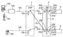
図1は、本発明の一実施例に係るADSLサービス通信系システムの基本構成を簡易に示した回路図である。このADSLサービス通信系システムの場合、図4に示した従来構成のものと比べ、加入者端末であるパソコン端末(PC)100及び電話機端末(TEL)101,電話機(TEL)104,ADSLシステム5及びPOTSシステム6の間に配置される図示されない主配線盤(MDF)上に配備される外線側端子板(OSP)1と局内側端子板(ISP)2との接続構成を変更すると共に、局内側端子板2をPOTSスプリッタ内蔵型とした点が相違している。
【0018】
具体的に言えば、ここでの外線側端子板1は、従来通りに加入者端末としてのパソコン端末(PC)100及び電話端末(TEL)101に接続された端末側POTSスプリッタ102と電話機(TEL)104とに対してそれぞれ電話回線103により接続されているが、局内側端子板2は、断器機能を有して対構成の組で配設された複数(ここでは1対2組で総計4個)の断器用コネクタ22a,22a′,22b,22b′と、データ信号と音声信号とを混合して分配可能にするためのローパスフィルタ(LPF),ハイパスフィルタ(HPF)を備えて成るPOTSスプリッタ回路を小型基板上に配備して成ると共に、POTSスプリッタカード接続端子31a31a′,31b,31b′を備えて各断器用コネクタ22a,22a′,22b,22b′に対して実装接続されるPOTSスプリッタカード3とを備えて成るPOTSスプリッタ内蔵型となっており、更に、各断器用コネクタ22a,22a′,22b,22b′にそれぞれ結合されたUスリット端子21a,21a′,21b,21b′の特定のものがそれぞれ外線側端子板1,ADSLシステム5,及びPOTSシステム6との間で接続される構成となっている。
【0019】
即ち、局内側端子板2の断器用コネクタ22bと結合されたUスリット端子21bは、外線側端子板1において電話回線103により端末側POTSスプリッタ102及び接地接続された保護サージ回路12aと接続されたUスリット端子11aとの間でジャンパ線10により接続され、局内側端子板2の断器用コネクタ22a′と結合されたUスリット端子21a′は、ADSL信号用ケーブル15によりADSLシステム5と接続され、局内側端子板2の断器用コネクタ22b′と結合されたUスリット端子21b′は、POTS信号用ケーブル16によりPOTSシステム6と接続されている。
【0020】
尚、このADSLサービス通信系システムでは、局内側端子板2の断器用コネクタ22bと結合されたUスリット端子21bと外線側端子板1において別の電話回線103により電話機104及び接地接続された保護サージ回路12bと接続されたUスリット端子11bとの間を接続しない構成としたが、これらの間を必要に応じてジャンパ線10により接続することも可能である。即ち、上述した局内側端子板2上の各Uスリット端子21a,21a′,21b,21b′のうち、Uスリット端子21a,21bは、外線側端子板1との接続を行うためのものであり、Uスリット端子21a′,21b′はADSLシステム5,POTSシステム6との接続を行うために用いられている。
【0021】
このような構成のADSLサービス通信系システムの場合、加入者端末との接続に供される外線側端子板1との間で接続される局内側端子板2を変更し、局内側端子板2上に搭載した対構成の断器用コネクタ22a,22a′,22b,22b′に対してPOTSスプリッタ回路を小型基板上に配備して成るPOTSスプリッタカード3を実装接続した上、断器用コネクタ21bと結合されたUスリット端子21bにはジャンパ線10により外線側端子板1のUスリット端子11a、断器用コネクタ22a′と結合されたUスリット端子21a′にはADSL信号用ケーブル15によりADSLシステム5、断器用コネクタ22b′と結合されたUスリット端子21b′にはPOTS信号用ケーブル16によりPOTSシステム6をそれぞれ接続した構成であるため、従来システムでADSLサービスの提供のために主配線盤上に増設する必要があった入力側スプリッタモジュール中継端子板(SPM−IN)及び出力側スプリッタモジュール中継端子板(SPM−OUT)とその間のケーブル接続とを不要にすることができ、これによって各部の接続が簡単でシステム全体を小規模で構築できるようになっている。
【0022】
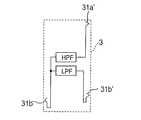
図2は、局内側端子板2上に配備されるPOTSスプリッタカード3の基本構成を示した回路図である。ここでのPOTSスプリッタカード3に実装されるPOTSスプリッタ回路では、POTSスプリッタカード接続端子31bがローパスフィルタ(LPF)及びハイパスフィルタ(HPF)の入力側の端子として接続され、POTSスプリッタカード接続端子31a′が高周波ADSL信号を通過させるためのハイパスフィルタ(HPF)出力側に接続され、POTSスプリッタカード接続端子31b′がPOTS用音声信号を通過させるためのローパスフィルタ(LPF)の出力側に接続された構成となっている。
【0023】
図3は、このPOTSスプリッタカード3の局内側端子板2に対する実装状態を示した外観図であり、同図(a)は一方向からの側面図に関するもの,同図(b)は他方向からの側面図に関するものである。ここでは、POTSスプリッタカード3は局内側端子板2上に対構成で設けられた断器用コネクタ22a,22a′,22b,22a’間に縦置きで実装接続されて装着された様子を示している。
【0024】
以下は、上述した一実施例に係るADSLサービス通信系システムの基本動作を図1に示した回路図と、図2に示したPOTSスプリッタカード3の回路図とを参照して説明する。
【0025】
このADSLサービス通信系システムにおいて、例えば初期的に電話機端末(TEL)101からの音声信号(POTS用信号)とパソコン端末(PC)100からのデータ信号(高周波ADSL信号)とが端末側POTSスプリッタ102に入力され、ここで合成された合成信号が電話回線103経由で主配線盤(MDF)上の外線側端子板1に入力されるものとする。
【0026】
この場合、外線側端子板1に入力された合成信号はUスリット端子11aへ出力され、このUスリット端子11aからジャンパ線10経由で局内側端子板2のUスリット端子21b端子に入力されると、引き続いて断器用コネクタ22b経由でPOTSスプリッタカード3に入力される。
【0027】
POTSスプリッタカード3では、POTSスプリッタカード接続端子31b経由で入力された合成信号をハイパスフィルタ(HPF)で高域濾波することでデータ信号としての高周波ADSL信号のみを取り出してPOTSスプリッタカード接続端子31a′へ出力し、又同様にPOTSスプリッタカード接続端子31b経由で入力された合成信号をローパスフィルタ(LPF)で低域濾波することで音声信号としてのPOTS用信号のみを取り出してPOTSスプリッタカード接続端子31b′へ出力する。
【0028】
そこで、POTSスプリッタカード3のPOTSスプリッタカード接続端子31a′から出力された高周波ADSL信号(データ信号)は局内側端子板2の断器用コネクタ22a′を経由してUスリット端子21a′からADSLシステム5に入力され、同様にPOTSスプリッタカード3のPOTSスプリッタカード接続端子31b′から出力されたPOTS用信号(音声信号)は局内側端子板2の断器用コネクタ22b′を経由してUスリット端子21b′からPOTSシステム6に入力される。
【0029】
このようにして、加入者端末である電話機端末(TEL)101からの音声信号(POTS用信号)とパソコン端末(PC)100からのデータ信号(高周波ADSL信号)とが動作処理される。
【0030】
ところで、ADSLシステム5からのデータ信号(高周波ADSL信号)とPOTSシステム6からの音声信号(POTS用信号)とは、ここで説明した信号経路と全く逆の経路でパソコン端末(PC)100と電話機端末(TEL)101とに伝送される。
【0031】
【発明の効果】
以上に説明したように、本発明のADSLサービス通信系システムによれば、加入者端末との接続に供される外線側端子板との間で接続される局内側端子板を変更し、局内側端子板上に搭載した対構成の断器用コネクタに対してPOTSスプリッタ回路を小型基板上に配備して成るPOTSスプリッタカードを実装接続した上、各断器用コネクタと結合されたUスリット端子の特定のものにジャンパ線,ADSL信号用ケーブル,POTS信号用ケーブルを用いて外線側端子板のUスリット端子,ADSLシステム,POTSシステムをそれぞれ接続する構成としているため、従来システムでADSLサービスの提供のために主配線盤上に増設する必要があった入力側スプリッタモジュール中継端子板(SPM−IN)及び出力側スプリッタモジュール中継端子板(SPM−OUT)とその間のケーブル接続とを不要にすることができ、これによって各部の接続が簡単でシステム全体を小規模で構築できるようになる。結果として、このADSLサービス通信系システムでは、従来のようにPOTSサービスのみからADSLサービスへの転換を行うために中継用端子板の増設等を行わなくても局内側端子板の切り分け断器部として働く断器用コネクタへPOTSスプリッタ回路を備えたPOTSスプリッタカードを実装接続して装着するだけで同等な機能を容易に得ることができるようになる。
【図面の簡単な説明】
【図1】本発明の一実施例に係るADSLサービス通信系システムの基本構成を簡易に示した回路図である。
【図2】図1に示すADSLサービス通信系システムに備えられる局内側端子板上に配備されるPOTSスプリッタカードの基本構成を示した回路図である。
【図3】図2で説明したPOTSスプリッタカードの局内側端子板に対する実装状態を示した外観図であり、(a)は一方向からの側面図に関するもの,(b)は他方向からの側面図に関するものである。
【図4】従来のADSLサービス通信系システムの基本構成を簡易に示した回路図である。
【符号の説明】
1 外線側端子板(OSP)
2,2′ 局内側端子板(ISP)
3 POTSスプリッタカード
4 主配線盤(MDF)
5 ADSLシステム
6 POTSシステム
7 スプリッタモジュール
8 入力側スプリッタモジュール中継端子板(SPM−IN)
9 出力側スプリッタモジュール中継端子板(SPM−OUT)
10 ジャンパ線
11a,11b,21a,21b,21a′,21b′,81a,81a′,91a,91a′ Uスリット端子
12a,12b サージ保護回路
15 ADSL信号用ケーブル
16,16a,16b POTS信号用ケーブル
22a,22a′,22b,22b′ 断器用コネクタ
31a,31a′,31b,31b′ POTSスプリッタカード接続端子
71a スプリッタモジュール入力端子
71a′ POTS接続端子
71a″ ADSL接続端子
100 パソコン端末(PC)
101 電話機端末(TEL)
102 端末側POTSスプリッタ
103 電話回線
104 電話機(TEL)[0001]
BACKGROUND OF THE INVENTION
The present invention mainly relates to an asymmetric digital subscriber with respect to an outside line terminal board connected to a terminal side telephone exchange splitter connected to a subscriber terminal, and to an outside line terminal board connected to the outside line side terminal board and the telephone exchange system. The present invention relates to an asymmetric digital subscriber line service communication system that is formed by connecting line systems.
[0002]
[Prior art]
Conventionally, as an ADSL service communication system for providing this type of asymmetric digital subscriber line (hereinafter referred to as ADSL) service, for example, a circuit configuration as shown in FIG.
[0003]
In this ADSL service communication system, a telephone exchange comprising a low-pass filter (LPF) and a high-pass filter (HPF) for mixing and distributing a data signal and a voice signal that are required when performing an ADSL service. After the splitter card 3 (hereinafter referred to as POTS) is mounted on the splitter module 7 having the splitter
[0004]
In this ADSL service communication system, the U-slit
[0005]
Furthermore, in this ADSL service communication system, the U-slit
[0006]
In addition, the U-slit
[0007]
In the case of this ADSL service communication system, of the U slit terminals used for each part,
[0008]
[Problems to be solved by the invention]
In the case of the above-described ADSL service communication system, when constructing a system for providing an ADSL service, the POTS splitter card is mounted on a splitter module having a dedicated terminal for POTS connection or ADSL connection, and is separately separately provided. Input side splitter module relay terminal board and output side splitter module relay terminal board are added on the wiring board, connection between input side splitter module relay terminal board and splitter module, output side splitter module relay terminal board and station inner terminal Connection between the boards, connection between the input-side splitter module relay terminal board and the splitter module is necessary, but in such a configuration, the connection configuration of each part becomes complicated and the entire system becomes large scale. Is cumbersome and difficult and the system There is a problem that can not be carried out Built to simplify.
[0009]
The present invention has been made to solve such problems, and its technical problem is to provide an ADSL service communication system that allows easy connection of each part and allows the entire system to be constructed on a small scale.
[0010]
[Means for Solving the Problems]
According to the present invention, an outside line side terminal board connected to a terminal side POTS splitter connected to a subscriber terminal, an outside line side terminal board and a local side terminal board connected to a POTS system, the outside line side terminal board is provided. In the ADSL service communication system that can connect the ADSL system to the station inner terminal board, the station inner terminal board has a breaker function and a plurality of breaker connectors arranged in pairs. Built-in POTS splitter circuit on which a POTS splitter circuit capable of mixing and distributing data signals and audio signals is provided on a small board, and includes a POTS splitter card mounted and connected to a plurality of circuit breaker connectors A type ADSL service communication system is obtained.
[0011]
Further, according to the present invention, in the ADSL service communication system, a plurality of breaker connectors are respectively coupled with U-slit terminals, and the plurality of U-slit terminals are respectively connected to an outside line side terminal plate, an ADSL system, and a POTS system. An ADSL service communication system including those connected to each other is obtained.
[0012]
Furthermore, according to the present invention, in the ADSL service communication system, the outside line side terminal plate is connected to the terminal side POTS splitter by a telephone line and between a specific one of the plurality of U slit terminals. Thus, an ADSL service communication system having U slit terminals connected by jumper wires can be obtained.
[0013]
In addition, according to the present invention, in any one of the ADSL service communication systems, the ADSL system is connected to a specific one of the plurality of U-slit terminals by an ADSL signal cable. A system is obtained.
[0014]
On the other hand, according to the present invention, in any one of the above ADSL service communication systems, the POTS system is connected to a specific one of a plurality of U-slit terminals by a POTS signal cable. A system is obtained.
[0015]
On the other hand, according to the present invention, in any one of the above ADSL service communication systems, an ADSL service communication system can be obtained in which the outer line side terminal board and the station inner terminal board are arranged on the main wiring board.
[0016]
DETAILED DESCRIPTION OF THE INVENTION
The ADSL service communication system according to the present invention will be described in detail below with reference to the drawings by giving examples.
[0017]
FIG. 1 is a circuit diagram schematically showing a basic configuration of an ADSL service communication system according to an embodiment of the present invention. In the case of this ADSL service communication system, a personal computer terminal (PC) 100 and a telephone terminal (TEL) 101, a telephone (TEL) 104, an
[0018]
More specifically, the external line side terminal board 1 here includes a terminal-
[0019]
That is, the U-slit terminal 21b coupled to the
[0020]
In this ADSL service communication system, the U-slit terminal 21b connected to the disconnecting
[0021]
In the case of the ADSL service communication system having such a configuration, the station inner
[0022]
FIG. 2 is a circuit diagram showing a basic configuration of the
[0023]
FIGS. 3A and 3B are external views showing a state in which the
[0024]
The basic operation of the ADSL service communication system according to one embodiment will be described below with reference to the circuit diagram shown in FIG. 1 and the circuit diagram of the
[0025]
In this ADSL service communication system, for example, a voice signal (POTS signal) from the telephone terminal (TEL) 101 and a data signal (high frequency ADSL signal) from the personal computer terminal (PC) 100 are initially converted to the terminal
[0026]
In this case, the combined signal input to the outer line side terminal plate 1 is output to the U slit
[0027]
In the
[0028]
Therefore, the high-frequency ADSL signal (data signal) output from the POTS splitter
[0029]
In this manner, the voice signal (POTS signal) from the telephone terminal (TEL) 101 as a subscriber terminal and the data signal (high frequency ADSL signal) from the personal computer terminal (PC) 100 are processed.
[0030]
By the way, the data signal (high frequency ADSL signal) from the
[0031]
【The invention's effect】
As described above, according to the ADSL service communication system of the present invention, the station inner terminal plate connected to the outside line terminal plate used for connection with the subscriber terminal is changed, and the station inner side is changed. A POTS splitter card having a POTS splitter circuit arranged on a small board is mounted and connected to a pair of breaker connectors mounted on a terminal board, and a specific U-slit terminal connected to each breaker connector is specified. To connect the U-slit terminal, ADSL system, and POTS system of the external line side terminal board using jumper wires, ADSL signal cables, and POTS signal cables, respectively, to provide ADSL services with conventional systems Input side splitter module relay terminal board (SPM-IN) and output side splitter that needed to be added on the main wiring board Joule relay terminal plate (SPM-OUT) and can be dispensed with and between the cable connection, whereby it becomes possible to construct a small scale the whole simple system connection units. As a result, in this ADSL service communication system, it is possible to use as a disconnecting and disconnecting part of the terminal board on the inside of the station without adding a relay terminal board or the like in order to switch from the POTS service only to the ADSL service as in the past. An equivalent function can be easily obtained simply by mounting and connecting a POTS splitter card having a POTS splitter circuit to a working breaker connector.
[Brief description of the drawings]
FIG. 1 is a circuit diagram schematically showing a basic configuration of an ADSL service communication system according to an embodiment of the present invention.
2 is a circuit diagram showing a basic configuration of a POTS splitter card provided on a station inner terminal board provided in the ADSL service communication system shown in FIG. 1. FIG.
FIGS. 3A and 3B are external views showing the mounting state of the POTS splitter card described in FIG. 2 with respect to the terminal plate on the inside of the station. FIG. 3A is a side view from one direction, and FIG. It relates to the figure.
FIG. 4 is a circuit diagram simply showing a basic configuration of a conventional ADSL service communication system.
[Explanation of symbols]
1 Outer terminal board (OSP)
2,2 'Station inner terminal board (ISP)
3 POTS splitter card 4 Main wiring board (MDF)
5
9 Output side splitter module relay terminal board (SPM-OUT)
10
101 Telephone terminal (TEL)
102 Terminal-
Claims (6)
Translated fromJapanesePriority Applications (3)
| Application Number | Priority Date | Filing Date | Title |
|---|---|---|---|
| JP2000297916AJP4632505B2 (en) | 2000-09-29 | 2000-09-29 | Asymmetric digital subscriber line service communication system |
| BR0105543ABR0105543A (en) | 2000-09-29 | 2001-09-27 | Adsl service communication system |
| CNB011361077ACN1180606C (en) | 2000-09-29 | 2001-09-29 | Asymmetric Digital Subscriber Line Service Communication System |
Applications Claiming Priority (1)
| Application Number | Priority Date | Filing Date | Title |
|---|---|---|---|
| JP2000297916AJP4632505B2 (en) | 2000-09-29 | 2000-09-29 | Asymmetric digital subscriber line service communication system |
Publications (2)
| Publication Number | Publication Date |
|---|---|
| JP2002112293A JP2002112293A (en) | 2002-04-12 |
| JP4632505B2true JP4632505B2 (en) | 2011-02-16 |
Family
ID=18779954
Family Applications (1)
| Application Number | Title | Priority Date | Filing Date |
|---|---|---|---|
| JP2000297916AExpired - Fee RelatedJP4632505B2 (en) | 2000-09-29 | 2000-09-29 | Asymmetric digital subscriber line service communication system |
Country Status (3)
| Country | Link |
|---|---|
| JP (1) | JP4632505B2 (en) |
| CN (1) | CN1180606C (en) |
| BR (1) | BR0105543A (en) |
Families Citing this family (2)
| Publication number | Priority date | Publication date | Assignee | Title |
|---|---|---|---|---|
| KR100425587B1 (en)* | 2002-04-26 | 2004-04-01 | 한국전자통신연구원 | Connection board incorporated with splitter in optical network unit |
| CN101478464B (en)* | 2009-01-22 | 2011-04-20 | 华为技术有限公司 | Digital subscriber line access method, apparatus and equipment |
Family Cites Families (3)
| Publication number | Priority date | Publication date | Assignee | Title |
|---|---|---|---|---|
| US6314102B1 (en)* | 1997-07-10 | 2001-11-06 | Alcatel | Telecommunications system for providing both narrowband and broadband services to subscribers |
| US6996232B1 (en)* | 1997-12-31 | 2006-02-07 | Corning Cable Systems Llc | XDSL splitter line module for network interface device |
| JPH11355435A (en)* | 1998-06-11 | 1999-12-24 | Fujitsu Ltd | High-speed communication system, subscriber transmission device, subscriber device, and communication service setting method |
- 2000
- 2000-09-29JPJP2000297916Apatent/JP4632505B2/ennot_activeExpired - Fee Related
- 2001
- 2001-09-27BRBR0105543Apatent/BR0105543A/ennot_activeIP Right Cessation
- 2001-09-29CNCNB011361077Apatent/CN1180606C/ennot_activeExpired - Fee Related
Also Published As
| Publication number | Publication date |
|---|---|
| CN1347240A (en) | 2002-05-01 |
| CN1180606C (en) | 2004-12-15 |
| BR0105543A (en) | 2002-05-21 |
| JP2002112293A (en) | 2002-04-12 |
Similar Documents
| Publication | Publication Date | Title |
|---|---|---|
| US6826280B1 (en) | Systems and methods for managing digital subscriber line (DSL) telecommunications connections | |
| US7145990B2 (en) | High-speed data communication over a residential telephone wiring network | |
| CN100359866C (en) | Telephone outlet and local area network system connected by telephone line | |
| TW518898B (en) | Systems and methods for electronically managing digital subscriber line (DSL) telecommunications connections | |
| JP2002533021A (en) | Network data filtering | |
| JP4632505B2 (en) | Asymmetric digital subscriber line service communication system | |
| JP3778018B2 (en) | Station inner terminal board, high-pass filter terminal board and main wiring board | |
| US20030147523A1 (en) | HPNA network bridge | |
| TWI246342B (en) | Metallic test access for xDSL connectors | |
| US7039732B1 (en) | Method and apparatus for providing redundancy between card elements in a chassis | |
| JP4076325B2 (en) | Communication device | |
| EP1626548B1 (en) | Processing apparatus of broadband and narrowband services in a communication device and method thereof | |
| CN101065978B (en) | Telecommunications modules, combinations of telecommunications modules and at least one splitter circuit, and assemblies of at least two telecommunications modules | |
| US20030086561A1 (en) | XDSL splitter module for field wiring cabinet | |
| JP2008517503A (en) | Integrated access device, associated modem box and split module | |
| CN100576867C (en) | Arrangement in a telecommunication system | |
| JP2001086148A (en) | Method and device for mutually connecting home networking device in dual communication dwelling | |
| JP2003069736A (en) | Splitter and digital transmission system using the splitter | |
| KR200195069Y1 (en) | A distributer of data transfer system useful telephone line | |
| US20030118172A1 (en) | VDSL system | |
| CA2548766A1 (en) | Module and connector |
Legal Events
| Date | Code | Title | Description |
|---|---|---|---|
| A621 | Written request for application examination | Free format text:JAPANESE INTERMEDIATE CODE: A621 Effective date:20070808 | |
| TRDD | Decision of grant or rejection written | ||
| A01 | Written decision to grant a patent or to grant a registration (utility model) | Free format text:JAPANESE INTERMEDIATE CODE: A01 Effective date:20101027 | |
| A01 | Written decision to grant a patent or to grant a registration (utility model) | Free format text:JAPANESE INTERMEDIATE CODE: A01 | |
| A61 | First payment of annual fees (during grant procedure) | Free format text:JAPANESE INTERMEDIATE CODE: A61 Effective date:20101116 | |
| R150 | Certificate of patent or registration of utility model | Free format text:JAPANESE INTERMEDIATE CODE: R150 | |
| FPAY | Renewal fee payment (event date is renewal date of database) | Free format text:PAYMENT UNTIL: 20131126 Year of fee payment:3 | |
| R250 | Receipt of annual fees | Free format text:JAPANESE INTERMEDIATE CODE: R250 | |
| R250 | Receipt of annual fees | Free format text:JAPANESE INTERMEDIATE CODE: R250 | |
| LAPS | Cancellation because of no payment of annual fees |