JP4630786B2 - Biochemical treatment apparatus, DNA amplification and purification apparatus, and DNA testing apparatus including the apparatus - Google Patents
Biochemical treatment apparatus, DNA amplification and purification apparatus, and DNA testing apparatus including the apparatusDownload PDFInfo
- Publication number
- JP4630786B2 JP4630786B2JP2005291298AJP2005291298AJP4630786B2JP 4630786 B2JP4630786 B2JP 4630786B2JP 2005291298 AJP2005291298 AJP 2005291298AJP 2005291298 AJP2005291298 AJP 2005291298AJP 4630786 B2JP4630786 B2JP 4630786B2
- Authority
- JP
- Japan
- Prior art keywords
- well
- unit
- nucleic acid
- thermal cycle
- purification
- Prior art date
- Legal status (The legal status is an assumption and is not a legal conclusion. Google has not performed a legal analysis and makes no representation as to the accuracy of the status listed.)
- Expired - Fee Related
Links
Images


Classifications
- B—PERFORMING OPERATIONS; TRANSPORTING
- B01—PHYSICAL OR CHEMICAL PROCESSES OR APPARATUS IN GENERAL
- B01L—CHEMICAL OR PHYSICAL LABORATORY APPARATUS FOR GENERAL USE
- B01L7/00—Heating or cooling apparatus; Heat insulating devices
- B01L7/52—Heating or cooling apparatus; Heat insulating devices with provision for submitting samples to a predetermined sequence of different temperatures, e.g. for treating nucleic acid samples
- B—PERFORMING OPERATIONS; TRANSPORTING
- B01—PHYSICAL OR CHEMICAL PROCESSES OR APPARATUS IN GENERAL
- B01L—CHEMICAL OR PHYSICAL LABORATORY APPARATUS FOR GENERAL USE
- B01L2200/00—Solutions for specific problems relating to chemical or physical laboratory apparatus
- B01L2200/10—Integrating sample preparation and analysis in single entity, e.g. lab-on-a-chip concept
- B—PERFORMING OPERATIONS; TRANSPORTING
- B01—PHYSICAL OR CHEMICAL PROCESSES OR APPARATUS IN GENERAL
- B01L—CHEMICAL OR PHYSICAL LABORATORY APPARATUS FOR GENERAL USE
- B01L2300/00—Additional constructional details
- B01L2300/08—Geometry, shape and general structure
- B01L2300/0809—Geometry, shape and general structure rectangular shaped
- B01L2300/0829—Multi-well plates; Microtitration plates
- B—PERFORMING OPERATIONS; TRANSPORTING
- B01—PHYSICAL OR CHEMICAL PROCESSES OR APPARATUS IN GENERAL
- B01L—CHEMICAL OR PHYSICAL LABORATORY APPARATUS FOR GENERAL USE
- B01L2300/00—Additional constructional details
- B01L2300/18—Means for temperature control
- B01L2300/1805—Conductive heating, heat from thermostatted solids is conducted to receptacles, e.g. heating plates, blocks
- B01L2300/1822—Conductive heating, heat from thermostatted solids is conducted to receptacles, e.g. heating plates, blocks using Peltier elements
- B—PERFORMING OPERATIONS; TRANSPORTING
- B01—PHYSICAL OR CHEMICAL PROCESSES OR APPARATUS IN GENERAL
- B01L—CHEMICAL OR PHYSICAL LABORATORY APPARATUS FOR GENERAL USE
- B01L2300/00—Additional constructional details
- B01L2300/18—Means for temperature control
- B01L2300/1805—Conductive heating, heat from thermostatted solids is conducted to receptacles, e.g. heating plates, blocks
- B01L2300/1827—Conductive heating, heat from thermostatted solids is conducted to receptacles, e.g. heating plates, blocks using resistive heater
- B—PERFORMING OPERATIONS; TRANSPORTING
- B01—PHYSICAL OR CHEMICAL PROCESSES OR APPARATUS IN GENERAL
- B01L—CHEMICAL OR PHYSICAL LABORATORY APPARATUS FOR GENERAL USE
- B01L7/00—Heating or cooling apparatus; Heat insulating devices
- B01L7/54—Heating or cooling apparatus; Heat insulating devices using spatial temperature gradients
- Y—GENERAL TAGGING OF NEW TECHNOLOGICAL DEVELOPMENTS; GENERAL TAGGING OF CROSS-SECTIONAL TECHNOLOGIES SPANNING OVER SEVERAL SECTIONS OF THE IPC; TECHNICAL SUBJECTS COVERED BY FORMER USPC CROSS-REFERENCE ART COLLECTIONS [XRACs] AND DIGESTS
- Y10—TECHNICAL SUBJECTS COVERED BY FORMER USPC
- Y10S—TECHNICAL SUBJECTS COVERED BY FORMER USPC CROSS-REFERENCE ART COLLECTIONS [XRACs] AND DIGESTS
- Y10S435/00—Chemistry: molecular biology and microbiology
- Y10S435/809—Incubators or racks or holders for culture plates or containers
Landscapes
- Health & Medical Sciences (AREA)
- Chemical & Material Sciences (AREA)
- Life Sciences & Earth Sciences (AREA)
- Biochemistry (AREA)
- General Health & Medical Sciences (AREA)
- Molecular Biology (AREA)
- Clinical Laboratory Science (AREA)
- Chemical Kinetics & Catalysis (AREA)
- Apparatus Associated With Microorganisms And Enzymes (AREA)
- Measuring Or Testing Involving Enzymes Or Micro-Organisms (AREA)
Description
Translated fromJapanese本発明は検体を生化学処理するための生化学処理装置に関する。特に、検体DNAを検査するDNA検査装置において使用する増幅および精製を行なう装置に関するものである。 The present invention relates to a biochemical processing apparatus for biochemically processing a specimen. In particular, the present invention relates to an apparatus for performing amplification and purification used in a DNA testing apparatus for testing sample DNA.
核酸の塩基配列の解析、核酸試料中の標的核酸の検出を迅速・正確に行なうものとして、DNAマイクロアレイに代表されるプローブ担体を用いたハイブリダイゼーション反応を利用した方法が多く提案されている。DNAマイクロアレイとは、標的核酸と相補的な塩基配列を有するプローブを、ビーズ、ガラス板等の固相上に高密度で固定したものであり、これを用いた標的核酸の検出は一般に以下のような工程を有する。 Many methods using a hybridization reaction using a probe carrier typified by a DNA microarray have been proposed as methods for rapidly and accurately detecting a base sequence of a nucleic acid and detecting a target nucleic acid in a nucleic acid sample. A DNA microarray is a probe having a base sequence complementary to a target nucleic acid fixed on a solid phase such as a bead or a glass plate at a high density. The detection of a target nucleic acid using this probe is generally as follows. It has a process.
第1の工程として、PCR法に代表される増幅方法によって、標的核酸を増幅する。具体的には、まず、核酸試料中に第1及び第2のプライマを加え、酵素の存在下で温度サイクルをかける。第1のプライマは標的核酸の一部と特異的に結合し、第2のプライマは標的核酸と相補的な核酸の一部と特異的に結合する。標的核酸を含む二本鎖核酸と第1及び第2のプライマが結合すると伸長反応によって標的核酸を含む二本鎖核酸が増幅される。(以降、第1PCRと呼ぶ。)
十分に標的核酸を含む二本鎖核酸が増幅された後に、未反応のプライマや核酸の断片など、増幅された二本鎖核酸以外のものを精製によって除去する。精製には磁性粒子に二本鎖核酸を吸着させる方法やカラムフィルタを利用したものなどが知られている。As a first step, a target nucleic acid is amplified by an amplification method typified by a PCR method. Specifically, first, first and second primers are added to a nucleic acid sample, and a temperature cycle is applied in the presence of an enzyme. The first primer specifically binds to a part of the target nucleic acid, and the second primer specifically binds to a part of the nucleic acid complementary to the target nucleic acid. When the double-stranded nucleic acid containing the target nucleic acid is bound to the first and second primers, the double-stranded nucleic acid containing the target nucleic acid is amplified by an extension reaction. (Hereafter referred to as the first PCR.)
After the double-stranded nucleic acid sufficiently containing the target nucleic acid has been amplified, other than the amplified double-stranded nucleic acid such as unreacted primer or nucleic acid fragment is removed by purification. For purification, a method of adsorbing double-stranded nucleic acid to magnetic particles, a method using a column filter, and the like are known.
精製を終了した核酸試料中に第3のプライマを加えて温度サイクルをかける。第3のプライマは、酵素、蛍光物質、発光物質等で標識されており、標的核酸と相補的な核酸の一部と特異的に結合する。標的核酸に相補的な核酸と、第3のプライマが結合すると伸長反応によって標識された標的核酸が増幅されるのである。(以降、第2PCRと呼ぶ。)
結果として、核酸試料中に標的核酸が含まれている場合は標識された標的核酸が生成され、核酸試料中に標的核酸が含まれない場合は標識された標的核酸は生成されない。A third primer is added to the purified nucleic acid sample and subjected to a temperature cycle. The third primer is labeled with an enzyme, a fluorescent substance, a luminescent substance, or the like, and specifically binds to a part of the nucleic acid complementary to the target nucleic acid. When the nucleic acid complementary to the target nucleic acid and the third primer are bound, the labeled target nucleic acid is amplified by the extension reaction. (Hereafter referred to as the second PCR.)
As a result, a labeled target nucleic acid is produced when the target nucleic acid is contained in the nucleic acid sample, and a labeled target nucleic acid is not produced when the target nucleic acid is not contained in the nucleic acid sample.
第2の工程として、この核酸試料をDNAマイクロアレイに接触させ、DNAマイクロアレイのプローブとハイブリダイゼーション反応させる。プローブと相補的な標的核酸がある場合は、プローブと標的核酸がハイブリッド体を形成する。 As a second step, the nucleic acid sample is brought into contact with a DNA microarray and subjected to a hybridization reaction with a probe of the DNA microarray. When there is a target nucleic acid complementary to the probe, the probe and the target nucleic acid form a hybrid.
第3の工程として、標的核酸の検出を行なう。プローブと標的核酸がハイブリッド体を形成しているかどうかは、標的核酸の標識物質によって検出が可能であり、これにより特定の塩基配列の有無を確認できる。 As a third step, the target nucleic acid is detected. Whether the probe and the target nucleic acid form a hybrid can be detected by a labeling substance of the target nucleic acid, thereby confirming the presence or absence of a specific base sequence.
この複数の工程を1つの装置で連続的に処理する装置に関して特許文献1で開示されている。移動可能な分注機により容器内に必要な液体を搬送して反応させる構成となっている。
生化学反応装置では試薬によっては、試薬の劣化を防ぐ必要がある。とりわけ生化学反応を行なうために重要な酵素は、常温で劣化し生化学反応に使用できなくなる場合があるため所定の温度以下に保冷する保冷部が必要である。これを装置内の限られたスペースで取り扱うには試薬の保冷部と反応部を近接させて配置させる必要がある。ところが増幅工程においては反応部では約55℃〜95℃の間でサーマルサイクルを行なうため保冷部を近接させて配置すると保冷部にサーマルサイクルの温度が伝わる可能性がある。また、増幅後の精製工程を限られたスペースに配置しなければならないという課題もある。 In a biochemical reaction apparatus, it is necessary to prevent deterioration of the reagent depending on the reagent. In particular, enzymes that are important for conducting biochemical reactions may deteriorate at room temperature and become unusable for biochemical reactions, and therefore, a cold insulation section that keeps the temperature below a predetermined temperature is required. In order to handle this in a limited space in the apparatus, it is necessary to place the reagent cold-reserving part and the reaction part close to each other. However, in the amplification process, since the thermal cycle is performed between about 55 ° C. and 95 ° C. in the reaction section, the temperature of the thermal cycle may be transmitted to the cold storage section if the cold storage section is placed close to each other. There is also a problem that the purification step after amplification must be arranged in a limited space.
特許文献1では装置を上面から見て左側に精製部、中央に加温部、右側に保冷部が配置されて容器を搬送させる構成となっている。このように各部分が離れた配置となっているため装置全体の幅が大きくなるとともに、容器を搬送させる距離が長くなり検査時間が長くなってしまうという課題があった。 In
すなわち、本発明は加熱部および保冷部を有する生化学処理装置において、装置の小型化、処理時間の短縮化に貢献する装置構成を提供することを目的とする。 That is, an object of the present invention is to provide an apparatus configuration that contributes to downsizing of the apparatus and shortening of processing time in a biochemical processing apparatus having a heating unit and a cold insulation unit.
上記課題を解決するために、本発明に係る生化学処理装置は、第1のウェルを配置して該第1のウェル内の溶液にサーマルサイクルを生ぜしめるサーマルサイクル部と、
前記第1のウェルに供給するための試薬類を有する第2のウェルを配置して、該第2のウェルの保冷を行なうための冷却部と、第3のウェルを配置して前記第1のウェル内にて処理された溶液を該第3のウェル内で精製するための精製部と、前記第1、第2および第3のウェル間で液体を移動させるためのピペットと、を有し、前記サーマルサイクル部と前記保冷部の間に、前記精製部が設けられている
ことを特徴とする生化学処理装置。In order to solve the above-described problems, a biochemical treatment apparatus according to the present invention includes athermal cycle unit that arranges a first well and generates a thermal cycle in a solution in the first well;
A second well having reagents to be supplied to the first well is arranged, a cooling unit for keeping the second well cold, and a third well are arranged to arrange the first well A purification unit for purifying the solution treated in the well in the third well, anda pipette for moving the liquid between the first, second and third wells ; The biochemical treatment apparatus, wherein the purification unit is provided between the thermal cycle unit and the cold insulation unit.
本発明に係る生化学反応装置は、加熱部、保冷部および精製反応部または試薬保持部が効率的に配置された載置部を有していることで、装置を小型化できる。特に、増幅精製装置におけるサーマルサイクル、保冷、精製といった各工程部を効率的に配置することにより装置を小型化することができる。 The biochemical reaction apparatus according to the present invention can be downsized by having a mounting section in which a heating section, a cold storage section and a purification reaction section or a reagent holding section are efficiently arranged. In particular, it is possible to reduce the size of the apparatus by efficiently arranging the respective process units such as thermal cycle, cold insulation, and purification in the amplification purification apparatus.
これにより、増幅精製装置を含むDNA検査装置の小型化も可能となる。 As a result, it is possible to reduce the size of the DNA test apparatus including the amplification and purification apparatus.
そして、各工程が近接しているので試薬、液体類を搬送する距離が従来よりも短くなる。これによって液体搬送中の液モレを防ぐことができるうえに処理時間の短縮化も可能となる。 And since each process is adjoining, the distance which conveys a reagent and liquids becomes shorter than before. As a result, liquid leakage during liquid conveyance can be prevented and processing time can be shortened.
増幅、ハイブリダイゼーション、検出の複数の工程を1つの装置で連続的に実施する装置の増幅部分を例に説明する。 An amplification part of an apparatus in which a plurality of steps of amplification, hybridization, and detection are continuously performed by one apparatus will be described as an example.
少なくとも液体が収容可能な複数の収容部を有する容器(反応・保存容器と呼ぶ)には市販されている96ウェルのPCRマイクロプレートもしくはそれと同等の形状にウェルを形成したものを用いるとよい。この反応・保存容器にはPCR工程で用いる試薬類があらかじめ充填されている。容器の一方側は第1および第2PCRを実施するウェル、中央部分は精製の際に使用するウェル、もう一方側は精製および第1、第2PCRで用いる試薬が充填されたウェルとなっている。 As a container (referred to as a reaction / storage container) having a plurality of storage parts capable of storing at least a liquid, a commercially available 96-well PCR microplate or one having wells formed in the same shape may be used. This reaction / storage container is pre-filled with reagents used in the PCR process. One side of the container is a well for performing the first and second PCRs, the central part is a well used for purification, and the other side is a well filled with reagents used for the purification and the first and second PCRs.
増幅装置側は大きく分けてサーマルサイクル部、精製部、保冷部で構成されている。この3つが反応・保存容器を動かさなくても各機能を果たせる近接した位置関係で配置されている。 The amplifier side is roughly divided into a thermal cycle section, a purification section, and a cold storage section. These three are arranged in close proximity so that each function can be performed without moving the reaction / storage container.
サーマルサイクル部は反応・保存容器と嵌合、密着する複数の凹部からなるアルミや銅合金などの熱伝導性の良い金属で形成したサーマルサイクルブロックとペルチェ素子やヒータなどで構成される。凹部の数は第1および第2PCRを実施するウェルと同数が形成されている。このサーマルサイクルブロックに反応・保存容器を嵌合させて第1および第2PCRを実施する。一般的には約92℃、55℃、72℃の3つの設定温度を各温度について所定時間保持し、このサイクルを40回程度(第1PCRにおいて)および25回程度(第2PCRにおいて)繰り返すものである。 The thermal cycle section is composed of a thermal cycle block formed of a metal having good thermal conductivity such as aluminum or copper alloy, which is formed of a plurality of concave portions which are fitted and closely attached to the reaction / storage container, and a Peltier element or a heater. The number of recesses is the same as the number of wells for performing the first and second PCR. The first and second PCR are performed by fitting the reaction / storage container to the thermal cycle block. Generally, three set temperatures of about 92 ° C., 55 ° C., and 72 ° C. are maintained for a predetermined time for each temperature, and this cycle is repeated about 40 times (in the first PCR) and about 25 times (in the second PCR). is there.
サーマルサイクル部は反応・保存容器の上部にも加熱部を備えている。この加熱部はアルミや銅合金などの熱伝導性の良い金属により構成された加熱ブロックと、ペルチェ素子やヒータなどからなり、加熱ブロックに熱を与えることにより反応・保存容器を上部から加熱する。加熱ブロックは第1および第2PCRの際にPCR反応を行なうウェルの上部のみを覆う大きさに構成されており、保冷ウェルを加熱しないように構成されている。これによりウェル内壁面温度が上昇するので、蒸発して上昇してきた溶液が内壁面に付着して結露するのを防止することができる。 The thermal cycle section also has a heating section at the top of the reaction / storage container. This heating unit is composed of a heating block made of a metal having good thermal conductivity such as aluminum or copper alloy, a Peltier element, a heater, and the like, and heats the reaction / storage container from above by applying heat to the heating block. The heating block is configured to cover only the upper part of the well in which the PCR reaction is performed during the first and second PCRs, and is configured not to heat the cold well. As a result, the temperature of the inner wall surface of the well rises, so that it is possible to prevent the solution that has risen by evaporation from adhering to the inner wall surface and causing condensation.
反応・保存容器の中央部に対向する位置には加熱または保冷を必要としない処理(精製)を行う精製部が配置されている。精製はウェルにあらかじめ充填された磁性粒子およびウェル近傍に配置した磁石を用いて行なう一般的な方法である。 A purification unit that performs processing (purification) that does not require heating or cooling is disposed at a position facing the center of the reaction / storage container. The purification is a general method performed using magnetic particles pre-filled in the well and a magnet arranged in the vicinity of the well.
このウェルに核酸溶液、洗浄液、エタノールなどを別々に供給後、攪拌し核酸を磁性粒子に吸着させる。その後、通常ウェルから離れた位置にある磁石を精製ウェルに近づけることにより核酸付き磁性粒子を1ヶ所に保持し、ウェルに核酸付き磁性粒子を残してウェル内の溶液を吸引する。次にこのウェルに溶出液を供給し磁性粒子から核酸を分離させ、磁石を精製ウェルに近づけて磁性粒子を1ヶ所に保持し磁性粒子以外の溶液を吸引する。このようなステップを経て精製された核酸溶液を得る。 A nucleic acid solution, a washing solution, ethanol and the like are separately supplied to the well and then stirred to adsorb the nucleic acid to the magnetic particles. Thereafter, the magnetic particles with nucleic acid are held in one place by bringing the magnet located at a position away from the normal well close to the purification well, and the solution in the well is aspirated leaving the magnetic particles with nucleic acid in the well. Next, the eluate is supplied to the well to separate the nucleic acid from the magnetic particles, the magnet is brought close to the purification well, the magnetic particles are held in one place, and the solution other than the magnetic particles is sucked. A purified nucleic acid solution is obtained through these steps.
反応・保存容器のサーマルサイクル部と反対側に対向する位置には保冷部が配置されている。保冷部は反応・保存容器と嵌合、密着する複数の凹部からなるアルミや銅合金などの熱伝導性の良い金属で形成した冷却ブロックとペルチェ素子などで構成される。凹部の数は少なくとも試薬類が充填されたウェルと同数が形成されている。冷却ブロックは周囲を断熱部材で覆われている。 A cold insulation part is arranged at a position opposite to the thermal cycle part of the reaction / storage container. The cold insulation portion is composed of a cooling block and a Peltier element formed of a metal having good thermal conductivity such as aluminum and copper alloy which are formed of a plurality of concave portions which are fitted and closely attached to the reaction / storage container. The number of recesses is at least the same as the number of wells filled with reagents. The cooling block is covered with a heat insulating member.
これらサーマルサイクル部、保冷部、精製部に対向するウェル間で溶液を移動させるピペットユニットが構成されている。ピペットユニットは先端に着脱可能なピペットチップを備えており、必要に応じて交換する。 A pipette unit is configured to move the solution between the wells facing the thermal cycle unit, the cold insulation unit, and the purification unit. The pipette unit is equipped with a detachable pipette tip at the tip and can be replaced as needed.
反応・保存容器が装置にセットされてから実際に使用されるまでの間、保冷部は試薬を劣化させない温度で保存している。試薬の保存温度は4℃〜20℃程度の範囲であり、近接したサーマルサイクル部の温度(55〜92℃)の影響を受けないでこの温度を維持しなければならない。 During the period from when the reaction / storage container is set to the apparatus until it is actually used, the cold storage section stores the reagent at a temperature that does not deteriorate the reagent. The storage temperature of the reagent is in the range of about 4 ° C. to 20 ° C., and this temperature must be maintained without being affected by the temperature of the adjacent thermal cycle part (55 to 92 ° C.).
保冷部とサーマルサイクル部の間に精製部を配置することにより距離をとってサーマルサイクル部と保冷部の温度が相互影響しないように構成されている。 By arranging a purification unit between the cold insulation unit and the thermal cycle unit, a distance is taken so that the temperatures of the thermal cycle unit and the cold insulation unit do not affect each other.
また、このようにサーマルサイクル部、保冷部、精製部を配置することによりPCRマイクロプレートの限られたサイズを効率的に使っているので装置の小型化をはかれるとともに、溶液を供給、吸引するピペットの移動距離を短くすることもできる。 In addition, the arrangement of the thermal cycle section, the cold storage section, and the purification section in this way efficiently uses the limited size of the PCR microplate, thereby reducing the size of the apparatus and supplying and sucking the solution. It is also possible to shorten the movement distance.
また、サーマルサイクル部と保冷部の間には、精製処理部に加えて、試薬、液体等の保存部を配置してもよい。この場合保存部に収容される材料は、精製部と同様、加熱または保冷を必要としない材料であることが好ましい。あるいは、廃液溜めとして構成する場合のように、その後の処理に影響の及ぼさない材料を保存するための保存部としてもよい。 In addition to the purification processing unit, a storage unit for reagents, liquids and the like may be arranged between the thermal cycle unit and the cold storage unit. In this case, the material accommodated in the storage unit is preferably a material that does not require heating or cold storage as in the purification unit. Or it is good also as a preservation | save part for preserve | saving the material which does not affect subsequent processes like the case where it comprises as a waste liquid reservoir.
(第1実施例)
DNA検査装置の増幅部分の例について説明する。(First embodiment)
An example of the amplification part of the DNA testing apparatus will be described.
図1にDNA検査装置の概念図を示す。 FIG. 1 shows a conceptual diagram of a DNA testing apparatus.
DNA検査装置201は生体試料からDNAを抽出する抽出部202、DNAを増幅させる増幅部203、増幅したDNAをプローブDNAと結合させるハイブリダイゼーション部204、プローブDNAと結合したかどうか検出する検出部205からなる。抽出部、増幅部、ハイブリダイゼーション部、検出部の順番に検査工程が進む。 The
図2は反応・保存容器のウェル部分を示す斜視図である。 FIG. 2 is a perspective view showing a well portion of the reaction / storage container.
ウェル部分は市販されているポリプロピレン製のPCRマイクロプレート1もしくはそれと同等の形状に形成したものを用いており、8×12個のウェルが9mmピッチで構成されている。各ウェルの先端(底)部2は後述するサーマルサイクルブロック、冷却ブロックと嵌合する形状になっている。 The well portion uses a commercially available
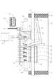
図3はDNA検査装置の増幅部を正面から見たもので、反応・保存容器の構造およびウェル配置とサーマルサイクル部、保冷部、精製部との位置関係などを説明するものである。 FIG. 3 is a front view of the amplifying unit of the DNA testing apparatus, and explains the structure of the reaction / storage container and the positional relationship between the well arrangement and the thermal cycle unit, the cold storage unit, and the purification unit.
図3は第1および第2PCR反応中の状態を示している。 FIG. 3 shows the state during the first and second PCR reactions.
反応・保存容器3は8×12個のウェルを1×12ウェルずつ12分割して利用し、同時に12検体の検査が可能となっている。 The reaction / storage container 3 uses 8 × 12 wells divided into 12 × 1 × 12 wells, and 12 samples can be tested at the same time.
右側のウェルから説明する。1番右のウェル4は第2PCRを行なうウェルであり最初は空である。ウェル5は第1PCRを行なうウェルであり酵素試薬、プライマなどの溶液101があらかじめ充填されている。ウェル6、7は精製を行なうウェルであり最初にウェル7から使う。ウェル7にはあらかじめ磁性粒子溶液102が充填されており、ウェル6は空である。ウェル8には洗浄液103、ウェル9にはエタノール104、ウェル10には溶出液105、もっとも左側のウェル11には第2PCRで使う試薬、プライマなどの溶液106があらかじめ充填されている。この配列が図面鉛直方向に12列並んでいる。 The explanation starts from the right well. The rightmost well 4 is a well for performing the second PCR and is initially empty. The well 5 is a well for performing the first PCR, and is prefilled with a
12はアルミなどで構成されたラミネートフィルムで96個のウェル開口部に接着もしくは溶着などにより固定されている。これにより外部からの異物混入を防ぐことができる。ウェルから溶液を吸引およびウェルに溶液を吐出する前に穴あけカッターでフィルム12を破る方式となっている。
13はシリコンゴム製の蓋、14は蓋を保持する部材、15は蓋13および蓋保持部材14を回動可能に保持する支点軸であり、支点軸15には蓋13および蓋保持部材14がウェル4、5を密閉する方向に付勢する不図示のねじりコイルバネが取り付けられている。16は支点軸15を回動可能に保持する軸受部である。ウェル部分に市販のPCRマイクロプレートを利用する場合、軸受部16は接着もしくはネジ止めなどでPCRマイクロプレートの縁部分17に固定される。またはPCRマイクロプレートに相当する部分と軸受部を一体化して作成してもよい。 13 is a lid made of silicon rubber, 14 is a member for holding the lid, 15 is a fulcrum shaft that rotatably holds the
蓋13はウェル4、5のみ12列計24ウェルを覆う大きさに構成されており後述する加熱ブロックと同等の大きさになっている。 The
18はサーマルサイクル部に配置されたサーマルサイクルブロックでアルミや銅合金などの熱伝導性の良い金属により構成され24個のウェル(穴部)が形成されている。
その下部にはサーマルサイクルブロック18を加熱するペルチェ素子19が配置されており、その接触面を完全に密着させて熱を確実に伝えるためのグリス(不図示)が塗布されている。グリス以外で同様な効果を得るものとして熱伝導性の良いシート材料もある。 A
ペルチェ素子19は反応・保存容器3の12列のウェルをすべて均一に加熱できる個数で配置されている。 The
ウェル4、5がサーマルサイクルブロック18と対向しており、外周がウェル内壁と密着する寸法関係となっている。 The wells 4 and 5 are opposed to the
なお、サーマルサイクルブロック18は周囲を樹脂で形成された断熱部材(不図示)で覆われており周囲に熱が逃げないように構成されている。 The
ウェル6、7の間には磁石20、磁石固定部材21、磁石回動支点22が配置され、磁石20、磁石固定部材21は精製工程における磁性粒子捕集のときは図3の23の位置にある。磁石20、磁石固定部材21は各列に対応し合計12個、磁石回動支点22に回動可能に保持されている。磁石回動支点22は後述する保持板32に形成された不図示の軸受手段により保持されている。磁石固定部材21は磁石20と反対側の端部が不図示のソレノイドと連結されている。磁性粒子をウェルの壁面に集中させたいときはソレノイドに電流を流して磁石固定部材21を引き込むことにより磁石20が23の位置まで上昇してくる。 A
24は保冷部に配置された冷却ブロックでアルミや銅合金などの熱伝導性の良い金属により構成され48個のウェル(穴部)が形成されている。
その下部には冷却ブロック24を冷却するペルチェ素子25が配置されており、その接触面を完全に密着させて熱を確実に伝えるためのグリス(不図示)が塗布されている。グリス以外で同様な効果を得るものとして熱伝導性の良いシート材料もある。 A
ペルチェ素子25は反応・保存容器3の12列のウェルをすべて均一に保冷できる個数で配置されている。 The
ウェル8〜11までが冷却ブロックと対向しており、外周がウェル内壁と密着する寸法関係となっている。 The
なお、冷却ブロック24は周囲を樹脂で形成された断熱部材(不図示)で覆われており周囲の温度影響を受けにくくしている。 The
26は反応・保存容器3を上部から加熱するユニットであり、27はアルミや銅合金により構成された加熱ブロックである。加熱ブロック27はウェル4、5の上部のみを覆う大きさに構成されており、ウェル6〜11を加熱しないように構成されている。加熱ブロック27の上部にはペルチェ素子28が配置されており、その接触面を完全に密着させて熱を確実に伝えるためのグリス(不図示)が塗布されている。 26 is a unit for heating the reaction / storage container 3 from above, and 27 is a heating block made of aluminum or copper alloy. The heating block 27 is configured to cover only the upper portions of the wells 4 and 5 and is configured not to heat the wells 6 to 11. A Peltier element 28 is disposed on the upper part of the heating block 27, and grease (not shown) is applied to bring the contact surface into close contact with each other and to reliably transfer heat.
ペルチェ素子28の上部には金属材料で形成された冷却ブロック29が、上記と同様に接触面にグリスを介して固定されている。ペルチェ素子28の裏から放熱するときにこの冷却ブロック29によって冷却を促進させる。 A
冷却ブロック29は出入口を備えた中空構造になっており、その出入口に接続された不図示の配管を介して冷却水が流れる構造となっている。 The
30は上面に開口31を備え、加熱ブロック27、ペルチェ素子28および冷却ブロック29を保持し、かつ断熱する部材である。
加熱ブロック27、ペルチェ素子28、冷却ブロック29、保持部材30が一つのユニット(天板ユニット)として構成されており、この天板ユニット26が不図示の駆動手段により、図中右方へ移動可能に構成されている。この天板ユニット26は反応・保存容器3の12列のウェルをすべて均一に加熱できるような幅で構成されている。 The heating block 27, the Peltier element 28, the
天板ユニット26は増幅時に反応・保存容器3のウェル4、5と密着する位置にあって上部から加熱する。 The top plate unit 26 is located in close contact with the wells 4 and 5 of the reaction / storage container 3 during amplification and is heated from above.
反応・保存容器3とサーマルサイクルブロック18、冷却ブロック24を嵌合させ、後述する保持板32を上昇させることにより反応・保存容器3を天板ユニット26に対して押圧している。これにより反応・保存容器3のウェル外周とサーマルサイクルブロック18、冷却ブロック24の密着性が向上しウェルへの熱伝導性がよくなる。 The reaction / storage container 3 is fitted to the
ペルチェ素子19、25の下にはこれらサーマルサイクル部、保冷部、精製部全体を保持する保持板32が配置されており、装置のベース33に不図示の軸受で支持されたリードスクリュー34および不図示のモータおよび駆動伝達系により図中上下に一体で駆動される。 Under the
保持板32の下面には金属材料で形成された水冷ブロック35、36が、上記と同様に接触面にグリスを介して固定されている。水冷ブロック35、36はペルチェ素子19、25の対向する位置にそれぞれ固定されておりペルチェ素子19、25の下面からの冷却を促進させる。ペルチェ素子19の下に配置される方は磁石固定部材21と干渉しない位置関係に配置されており、図中には点線で位置を示す。 On the lower surface of the holding
冷却ブロック35、36は出入口を備えた中空構造になっており、出入口に接続された不図示の配管を介して冷却水が流れる構造となっている。 The cooling blocks 35 and 36 have a hollow structure provided with an entrance and exit, and have a structure in which cooling water flows through a pipe (not shown) connected to the entrance and exit.
点線37であらわされているのは反応・保存容器3をセットするキャリッジ部で不図示のモータおよび駆動伝達系を介して図面鉛直方向に配置されているリードスクリュー38およびガイドシャフト39により前後にキャリッジ部37を駆動する。点線37の高さは反応・保存容器3をセットする高さであり、キャリッジ37が装置前面にあるときに反応・保存容器をセットする。キャリッジ37が装置後方に駆動されて反応・保存容器3がサーマルサイクル部、保冷部、精製部と対向する位置に到達すると停止する。このとき保持板32は図3で示される位置より下方、反応・保存容器3とぶつからない位置にある。その後、リードスクリュー34で保持板32を図3の位置まで上昇させる。 A dotted
次にDNA検査装置の動作について説明する。 Next, the operation of the DNA testing apparatus will be described.
なお、以降は1列(1検体分)の動きを説明するが他の列も同様に動作している。 In the following, the movement of one column (for one sample) will be described, but the other columns operate in the same manner.
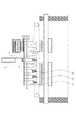
図4は図3の上面図であり天板ユニット26およびその他を除いた要部をあらわしたものである。 FIG. 4 is a top view of FIG. 3 and shows the main part excluding the top plate unit 26 and others.
使用者が反応・保存容器3を点線40の位置にあるキャリッジ37にセットすると不図示の駆動モータ、リードスクリュー38によって反応・保存容器3を後方(図中上方)に搬送する。実線の位置まで到達するとリードスクリュー38によって支持板32が上昇し、図5の状態となる。 When the user sets the reaction / storage container 3 on the
図5は図3よりも支持板32がわずかに下にあり加熱ブロック27と蓋13は接触していない。 In FIG. 5, the
すでに不図示の抽出部によって血液、尿などの生体試料から公知の手段により抽出された核酸を含む溶液をウェル5へ移動させる。 A solution containing nucleic acid that has already been extracted from a biological sample such as blood or urine by a known means by an extraction unit (not shown) is moved to the well 5.
核酸溶液の移動にはピペットを用いる。 Use a pipette to move the nucleic acid solution.
図6はピペットを用いて核酸溶液をウェル5へ吐出している様子をあらわしたものである。 FIG. 6 shows a state in which the nucleic acid solution is discharged to the well 5 using a pipette.
41は先端に着脱可能に取り付けられたピペットチップ42を介して溶液の供給・吐出・攪拌を行なうピペット部、およびその搬送部でモータ、リードスクリューなどから構成される。ピペット部は不図示のピペット搬送部により上下前後左右に移動可能に構成されている。
この他、ピペットチップの図中右側にウェルを密閉しているフィルムに穴をあけるカッター部、周辺には未使用のピペットチップを保持しておくピペットホルダ部、および使用済みピペットチップを収容するピペット廃却部などが構成されている。カッター部はピペット搬送部で所定の位置に搬送される。(以上不図示)
あらかじめフィルム12のウェル5に対向する部分にカッター部で穴をあけておきピペットチップ42がウェル5内に進入できる状態になっている。In addition to this, a cutter part that makes a hole in the film sealing the well on the right side of the pipette tip in the figure, a pipette holder part that holds an unused pipette tip in the periphery, and a pipette that contains a used pipette tip Disposal department etc. are configured. The cutter unit is transported to a predetermined position by the pipette transport unit. (The above is not shown)
A hole is made in advance in the portion of the
なお、穴をあける前に天板ユニット26および蓋13は不図示の駆動機構によりそれぞれ右方へ移動および略90回転させて、ウェル4、5の上面が開放状態にしておく。 Before the hole is made, the top plate unit 26 and the
図中右方にある抽出部から核酸溶液を吸引したピペットチップ42をウェル5の上方まで移動後、下降させてウェル5内に進入させ、所定の深さまで進入させたら核酸溶液を吐出する。 After moving the
その後、ウェルにピペットチップを入れたまま吸引、吐出を所定回数繰り返し、あらかじめ充填されていた試薬類とじゅうぶんに混合(攪拌)する。 Thereafter, suction and discharge are repeated a predetermined number of times with the pipette tip in the well, and the mixture is thoroughly mixed (stirred) with the pre-filled reagents.
混合を終了したらピペット部41を反応・保存容器3上から退避させ、天板ユニット26および蓋13を図5の状態にしておく。 When mixing is completed, the
その後、リードスクリュー34により保持板32を上昇させて図3の状態にする。 Thereafter, the holding
このとき蓋13は保持板32を天板ユニット26に付勢することによりウェル1ヶ所あたり50〜100gf、場合によってはそれ以上の力で押圧される構造となっている。 At this time, the
図3の状態で第1PCRを開始する。約92〜55〜72℃の間を所定の保持時間、サイクル数で実施することにより試料管内の核酸が増幅される。第1PCRの間、保冷部は試薬類が劣化しない温度、例えば4℃程度に維持される。サーマルサイクル部(ウェル4、5)と保冷部(ウェル8〜11)は要部を不図示の断熱部材で覆われている上に、間に精製部(ウェル6、7)を配置しているためある程度の距離が確保されている。 The first PCR is started in the state shown in FIG. The nucleic acid in the sample tube is amplified by performing between 92 and 55 to 72 ° C. with a predetermined holding time and the number of cycles. During the first PCR, the cold insulator is maintained at a temperature at which the reagents do not deteriorate, for example, about 4 ° C. The main parts of the thermal cycle part (wells 4 and 5) and the cold insulation part (
このように配置することによってサーマルサイクル部と保冷部の温度が相互に影響を与えないようになっている。 By arranging in this way, the temperatures of the thermal cycle part and the cold insulation part do not affect each other.
第1PCR終了後、精製工程が始まる。 After the completion of the first PCR, the purification process begins.
図7は増幅産物中の核酸を磁性粒子に吸着させた後、磁石20で磁性粒子を集めて核酸付き磁性粒子43以外をピペットチップ42に吸引した状態を示している。 FIG. 7 shows a state in which the nucleic acid in the amplification product is adsorbed to the magnetic particles, and then the magnetic particles are collected by the
ウェル5内の溶液ピペットチップ42により吸引しウェル7に吐出する。(事前にカッター部によりウェル7に穴をあけておく)
次にウェル7にあらかじめ充填されている磁性粒子溶液102とウェル5から移動した溶液をピペットチップ42で攪拌し、核酸を磁性粒子にじゅうぶん吸着させた後、磁石20を図7の位置まで上昇させて核酸付き磁性粒子43をウェル7内壁の1ヶ所に集中させる。ここで図7のようにピペットチップ42により核酸付き磁性粒子43以外を吸引し不図示の廃液処理部分に吐出する。なお第1PCRが終了したらサーマルサイクルブロックの温度は室温程度にしてよい。The solution is picked up by the
Next, the
次に磁石20をウェル7から遠ざけて、ウェル8に穴をあけて中の洗浄液103を吸引しウェル7へ移動させ、ピペットチップ42により攪拌し、磁石20を上昇させて核酸付き磁性粒子をウェル8内壁の1ヶ所に集中させる。ここでピペットチップ42により核酸付き磁性粒子43以外を吸引し(図7と同様の状態である)不図示の廃液処理部分に吐出する。 Next, the
この流れと同様にウェル9のエタノール104をウェル7に移動させて核酸付き磁性粒子43以外を吸引して不図示の廃液処理部に吐出する。 Similarly to this flow, the
ここで精製工程中の洗浄工程終了である。 This is the end of the washing step in the purification step.
最後に核酸付き磁性粒子43から核酸を溶出させる工程に移る。 Finally, the process proceeds to the step of eluting the nucleic acid from the magnetic particle with
ウェル7内の溶液およびウェル10の溶出液をウェル6へ移動し、洗浄液、エタノールのときと同様に攪拌、放置を経て磁石20により1ヶ所に磁性粒子を集める。溶出液によって磁性粒子から核酸が離れており、この溶液が精製を経て得られた核酸溶液である。これをウェル6から所定量吸引して(図7と同様の状態である)ウェル4に移動させる。あらかじめ任意のタイミングでカッター部によりウェル4に穴をあけておく。 The solution in the well 7 and the eluate in the well 10 are moved to the well 6, and the magnetic particles are collected in one place by the
ここで精製工程終了である。 This is the end of the purification process.
次にウェル11に穴をあけて第2PCRで使用する溶液106をウェル4に移動させ、ピペットチップ42により攪拌する。攪拌が終了したら図5の状態を経て図3の状態とし、第2PCRを開始する。すでに試薬類はすべて使い切っているので第2PCRの間は冷却ブロック24の冷却を停止してもよい。
第2PCRが終了したら天板ユニット26および蓋13を図6の状態として、ピペットチップ42によりウェル5から増幅産物を不図示のハイブリダイゼーション部に移動させる。移動が終了し、再度図3の状態にしてから保持板32を下降させてキャリッジ部37を手前に搬送すると反応・保存容器3をDNA検査装置から取り外し可能な状態となる。Next, a hole is made in the well 11 and the
When the second PCR is completed, the top plate unit 26 and the
図3で説明したように反応・保存容器3にあらかじめ充填しておく溶液を使用する順番に配置し、未使用(穴をあけていない)ウェル上を溶液を吸引したピペットチップがなるべく通過しないように構成した。こうした配列にすることにより仮にピペットチップから溶液が落下しても、未使用ウェルに落下する可能性は小さいので増幅工程および精製工程に影響を与えることはない。 As described with reference to FIG. 3, the reaction / storage containers 3 are preliminarily filled with the solutions in the order in which they are used, and pipette tips that have sucked the solution through unused (not punctured) wells do not pass as much as possible. Configured. By adopting such an arrangement, even if the solution falls from the pipette tip, the possibility of dropping into an unused well is small, so that the amplification process and the purification process are not affected.
(第2実施例)
上記実施例では反応・保存容器として各ウェルが9mmピッチで構成された市販のPCRマイクロプレートもしくはそれと同等な形状のものを用いているが、本発明はこれに限定されるものではない。必要に応じてさらに狭いピッチもしくは多少大きいピッチで構成された反応・保存容器およびサーマルサイクルブロック、保冷ブロックを用いても良い。ウェル個数も96個に限定されるものではなく試薬種類、処理したい検体数に応じて適切な数を設定すれば良い。(Second embodiment)
In the above embodiment, a commercially available PCR microplate in which each well is configured with a 9 mm pitch or a similar shape is used as a reaction / storage container, but the present invention is not limited to this. If necessary, a reaction / storage container, a thermal cycle block, and a cold block configured with a narrower pitch or a slightly larger pitch may be used. The number of wells is not limited to 96, and an appropriate number may be set according to the type of reagent and the number of samples to be processed.
また、ウェル形状も先端がテーパ上になった円筒に限らず他の形状でも良い。サーマルサイクルブロックおよび保冷ブロックとウェルが密着可能で、かつ精製可能に構成されていればよい。 Further, the well shape is not limited to a cylinder having a tapered tip, and may have other shapes. It is sufficient that the thermal cycle block and the cold insulation block and the well can be in close contact with each other and can be purified.
(第3実施例)
上記実施例では反応・保存容器3には増幅工程に関わる試薬類のみが充填されていたが、他の工程(抽出・ハイブリ・検出)の試薬が一緒に充填されていてもよい。(Third embodiment)
In the above embodiment, the reaction / storage container 3 is filled only with reagents related to the amplification step, but may be filled together with reagents of other steps (extraction / hybridization / detection).
その際、温度管理不要のもの、温度により劣化しない溶液は保冷部とサーマルサイクル部の間のウェルに充填してもよい。 At that time, a solution that does not require temperature control and a solution that does not deteriorate due to temperature may be filled in the well between the cold insulation unit and the thermal cycle unit.
(第4実施例)
上記実施例では精製に磁性粒子と磁石を用いているがカラムフィルタを用いても良い。(Fourth embodiment)
In the above embodiment, magnetic particles and magnets are used for purification, but a column filter may be used.
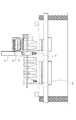
図8〜10はその説明図であり上記実施例と同じ符号は一部省略してある。 8 to 10 are explanatory diagrams thereof, and the same reference numerals as those in the above embodiment are partially omitted.
反応・保存容器3の構成および充填されている試薬類の配置は上記実施例と同じである。 The configuration of the reaction / storage container 3 and the arrangement of the filled reagents are the same as in the above embodiment.
図8で44はカラムフィルタであり45はその中に固定されたフィルタを示している。第1PCRが終了したら不図示の駆動機構により12個のカラムフィルタをウェル7上に保持する。次にウェル5内の第1PCR後の溶液とウェル8内の洗浄液をピペットチップ42でカラム44の中に順次吐出する。図8は溶液を吐出した状態を示しており46は第1PCR溶液と洗浄液の混合液である。 In FIG. 8,
図9は混合液46を加圧してフィルタ45を通過させた状態を示している。カラム44の上方に不図示の駆動機構により加圧ポンプ47を密着させて図中下方へ加圧する。これにより混合液46の中の核酸がフィルタ45に吸着しその他の成分がフィルタ45を通過してウェル7に集まる。 FIG. 9 shows a state in which the mixed liquid 46 is pressurized and passed through the
図8、9の流れと同様にウェル9のエタノールをカラム44内に移動させた後、加圧ポンプ47で加圧して不要なものをウェル7に集める。 8 and 9, the ethanol in the well 9 is moved into the
次にカラム44をウェル6上に移動させて保持する。ウェル10の溶出液105をカラム44の中に吐出した後、図10のように加圧ポンプ47をカラム44上方に密着させて図中下方へ加圧する。これによりフィルタ45に吸着していた核酸が溶出液とともにウェル6に集まる。この溶液48が精製された核酸溶液であり、ここで精製が終了する。カラム44をウェル6上から退避させて核酸溶液48をピペットチップで吸引する。 Next, the
この後の動作は上記実施例と同じである。この実施例においてもサーマルサイクル部と保冷部の間に精製部が配置されており、上記実施例と同様の効果を得られる。 The subsequent operation is the same as in the above embodiment. Also in this embodiment, the purification section is arranged between the thermal cycle section and the cold insulation section, and the same effect as the above embodiment can be obtained.
1 PCRマイクロプレート
3 反応・保存容器
4 第2PCRを行なうウェル
5 第1PCRを行なうウェル
6、7 精製を行なうウェル
8 洗浄液103が充填されたウェル
9 エタノール104が充填されたウェル
10 溶出液105が充填されたウェル
11 第2PCR用溶液106が充填されたウェル
12 フィルム
13 蓋
18 サーマルサイクルブロック
19 サーマルサイクル用ペルチェ素子
20 磁石
24 冷却ブロック
25 保冷用ペルチェ素子
26 天板ユニット
32 保持板
34 リードスクリュー
35、36 水冷ブロック
37 キャリッジ部
38 リードスクリュー
40 反応・保存容器3をセットする位置
42 ピペットチップ
101 プライマなどの溶液101
102 磁性粒子溶液DESCRIPTION OF
102 Magnetic particle solution
Claims (6)
Translated fromJapanese第1のウェルを配置して該第1のウェル内の溶液にサーマルサイクルを生ぜしめるサーマルサイクル部と、
前記第1のウェルに供給するための試薬類を有する第2のウェルを配置して、該第2のウェルの保冷を行なうための冷却部と、
第3のウェルを配置して前記第1のウェル内にて処理された溶液を該第3のウェル内で精製するための精製部と、
前記第1、第2および第3のウェル間で液体を移動させるためのピペットと、
を有し、
前記サーマルサイクル部と前記保冷部の間に、前記精製部が設けられている
ことを特徴とする生化学処理装置。A biochemical processing apparatusfor performing biochemical processing using a plurality of wells ,
A thermal cycle partfor arranging a first well andcausing a thermal cyclein the solutionin the first well ;
Disposing a second well having reagents to be supplied to the first well, and a cooling unit for keeping thesecond well cold;
A purification unit fordisposing a third well and purifyingthe solution treated in the first well in the third well;
A pipette for moving liquid between the first, second and third wells;
Have
The biochemical treatment apparatus, wherein the purification unit is provided between the thermal cycle unit and the cold insulation unit.
核酸溶液の精製を行う前記第3のウェル、
前記PCRにて用いられる溶液を収容する前記第2のウェル、
がこの順序で配列して一体化された反応・保存容器を有する請求項1記載の生化学処理装置。The first well for performing PCR to amplify at least the labeled target nucleic acid;
The third well for purifying the nucleic acid solution;
The second well containing a solution used in the PCR;
The biochemical processing apparatus according to claim 1, further comprising a reaction / storage container thatis arranged and integrated inthis order .
Priority Applications (3)
| Application Number | Priority Date | Filing Date | Title |
|---|---|---|---|
| JP2005291298AJP4630786B2 (en) | 2005-10-04 | 2005-10-04 | Biochemical treatment apparatus, DNA amplification and purification apparatus, and DNA testing apparatus including the apparatus |
| US11/528,601US7879595B2 (en) | 2005-10-04 | 2006-09-28 | Apparatus for performing biochemical processing using container having wells |
| US13/004,684US20110104794A1 (en) | 2005-10-04 | 2011-01-11 | Apparatus for performing biochemical processing using container having wells |
Applications Claiming Priority (1)
| Application Number | Priority Date | Filing Date | Title |
|---|---|---|---|
| JP2005291298AJP4630786B2 (en) | 2005-10-04 | 2005-10-04 | Biochemical treatment apparatus, DNA amplification and purification apparatus, and DNA testing apparatus including the apparatus |
Publications (3)
| Publication Number | Publication Date |
|---|---|
| JP2007097477A JP2007097477A (en) | 2007-04-19 |
| JP2007097477A5 JP2007097477A5 (en) | 2007-08-09 |
| JP4630786B2true JP4630786B2 (en) | 2011-02-09 |
Family
ID=37902386
Family Applications (1)
| Application Number | Title | Priority Date | Filing Date |
|---|---|---|---|
| JP2005291298AExpired - Fee RelatedJP4630786B2 (en) | 2005-10-04 | 2005-10-04 | Biochemical treatment apparatus, DNA amplification and purification apparatus, and DNA testing apparatus including the apparatus |
Country Status (2)
| Country | Link |
|---|---|
| US (2) | US7879595B2 (en) |
| JP (1) | JP4630786B2 (en) |
Families Citing this family (47)
| Publication number | Priority date | Publication date | Assignee | Title |
|---|---|---|---|---|
| US6692700B2 (en) | 2001-02-14 | 2004-02-17 | Handylab, Inc. | Heat-reduction methods and systems related to microfluidic devices |
| US8895311B1 (en) | 2001-03-28 | 2014-11-25 | Handylab, Inc. | Methods and systems for control of general purpose microfluidic devices |
| US7829025B2 (en) | 2001-03-28 | 2010-11-09 | Venture Lending & Leasing Iv, Inc. | Systems and methods for thermal actuation of microfluidic devices |
| US6852287B2 (en) | 2001-09-12 | 2005-02-08 | Handylab, Inc. | Microfluidic devices having a reduced number of input and output connections |
| US7010391B2 (en) | 2001-03-28 | 2006-03-07 | Handylab, Inc. | Methods and systems for control of microfluidic devices |
| EP2407243B1 (en) | 2003-07-31 | 2020-04-22 | Handylab, Inc. | Multilayered microfluidic device |
| US8852862B2 (en) | 2004-05-03 | 2014-10-07 | Handylab, Inc. | Method for processing polynucleotide-containing samples |
| JP4682008B2 (en)* | 2005-10-04 | 2011-05-11 | キヤノン株式会社 | Biochemical treatment equipment, containers and inspection equipment used therefor |
| JP4981295B2 (en)* | 2005-10-04 | 2012-07-18 | キヤノン株式会社 | DNA processing method and DNA processing apparatus |
| JP4630786B2 (en)* | 2005-10-04 | 2011-02-09 | キヤノン株式会社 | Biochemical treatment apparatus, DNA amplification and purification apparatus, and DNA testing apparatus including the apparatus |
| US10900066B2 (en) | 2006-03-24 | 2021-01-26 | Handylab, Inc. | Microfluidic system for amplifying and detecting polynucleotides in parallel |
| WO2007112114A2 (en) | 2006-03-24 | 2007-10-04 | Handylab, Inc. | Integrated system for processing microfluidic samples, and method of using same |
| US11806718B2 (en) | 2006-03-24 | 2023-11-07 | Handylab, Inc. | Fluorescence detector for microfluidic diagnostic system |
| US8883490B2 (en) | 2006-03-24 | 2014-11-11 | Handylab, Inc. | Fluorescence detector for microfluidic diagnostic system |
| US7998708B2 (en)* | 2006-03-24 | 2011-08-16 | Handylab, Inc. | Microfluidic system for amplifying and detecting polynucleotides in parallel |
| WO2008061165A2 (en) | 2006-11-14 | 2008-05-22 | Handylab, Inc. | Microfluidic cartridge and method of making same |
| EP3222733B1 (en) | 2007-07-13 | 2021-04-07 | Handylab, Inc. | Polynucleotide capture materials, and methods of using same |
| US8105783B2 (en) | 2007-07-13 | 2012-01-31 | Handylab, Inc. | Microfluidic cartridge |
| US9618139B2 (en) | 2007-07-13 | 2017-04-11 | Handylab, Inc. | Integrated heater and magnetic separator |
| US9186677B2 (en) | 2007-07-13 | 2015-11-17 | Handylab, Inc. | Integrated apparatus for performing nucleic acid extraction and diagnostic testing on multiple biological samples |
| US8133671B2 (en) | 2007-07-13 | 2012-03-13 | Handylab, Inc. | Integrated apparatus for performing nucleic acid extraction and diagnostic testing on multiple biological samples |
| US8182763B2 (en) | 2007-07-13 | 2012-05-22 | Handylab, Inc. | Rack for sample tubes and reagent holders |
| AU2015249160B2 (en)* | 2007-07-13 | 2017-10-12 | Handylab, Inc. | Integrated apparatus for performing nucleic acid extraction and diagnostic testing on multiple biological samples |
| US8287820B2 (en) | 2007-07-13 | 2012-10-16 | Handylab, Inc. | Automated pipetting apparatus having a combined liquid pump and pipette head system |
| US20090181359A1 (en)* | 2007-10-25 | 2009-07-16 | Lou Sheng C | Method of performing ultra-sensitive immunoassays |
| US8222048B2 (en) | 2007-11-05 | 2012-07-17 | Abbott Laboratories | Automated analyzer for clinical laboratory |
| US8691149B2 (en)* | 2007-11-06 | 2014-04-08 | Abbott Laboratories | System for automatically loading immunoassay analyzer |
| DE102008009920A1 (en)* | 2008-02-15 | 2009-08-20 | Aj Innuscreen Gmbh | Mobile device for nucleic acid isolation |
| USD787087S1 (en) | 2008-07-14 | 2017-05-16 | Handylab, Inc. | Housing |
| EP2191900B1 (en)* | 2008-11-28 | 2016-03-30 | F. Hoffmann-La Roche AG | System and method for nucleic acids containing fluid processing |
| EP2192186B1 (en)* | 2008-11-28 | 2016-03-09 | F. Hoffmann-La Roche AG | System and method for the automated extraction of nucleic acids |
| GB2511692A (en)* | 2009-08-08 | 2014-09-10 | Bibby Scient Ltd | An apparatus for treating a test sample |
| GB201016014D0 (en) | 2010-09-24 | 2010-11-10 | Epistem Ltd | Thermal cycler |
| GB201018624D0 (en)* | 2010-11-04 | 2010-12-22 | Epistem Ltd | Reaction vessel |
| CN106190806B (en) | 2011-04-15 | 2018-11-06 | 贝克顿·迪金森公司 | Scan real-time microfluid thermal cycler and the method for synchronous thermal cycle and scanning optical detection |
| USD692162S1 (en) | 2011-09-30 | 2013-10-22 | Becton, Dickinson And Company | Single piece reagent holder |
| CA2849917C (en) | 2011-09-30 | 2020-03-31 | Becton, Dickinson And Company | Unitized reagent strip |
| WO2013067202A1 (en) | 2011-11-04 | 2013-05-10 | Handylab, Inc. | Polynucleotide sample preparation device |
| EP2810080B1 (en) | 2012-02-03 | 2024-03-27 | Becton, Dickinson and Company | External files for distribution of molecular diagnostic tests and determination of compatibility between tests |
| CN102943031A (en)* | 2012-10-30 | 2013-02-27 | 无锡耐思生物科技有限公司 | 96-well polymerase chain reaction tandem alignment tube structure |
| US10220392B2 (en) | 2013-03-15 | 2019-03-05 | Becton, Dickinson And Company | Process tube and carrier tray |
| US11865544B2 (en) | 2013-03-15 | 2024-01-09 | Becton, Dickinson And Company | Process tube and carrier tray |
| CA2905204C (en) | 2013-03-15 | 2021-08-10 | Becton, Dickinson And Company | Process tube and carrier tray |
| WO2016017832A1 (en)* | 2014-07-30 | 2016-02-04 | 이현영 | Nucleic acid amplification device |
| CN105543089A (en)* | 2016-03-08 | 2016-05-04 | 湖南圣湘生物科技有限公司 | Magnetic bead based nucleic acid extraction device and method |
| GB201604062D0 (en) | 2016-03-09 | 2016-04-20 | Cell Therapy Catapult Ltd | A device for heating or cooling a sample |
| WO2017169192A1 (en) | 2016-03-28 | 2017-10-05 | 富士フイルム株式会社 | Pcr container |
Family Cites Families (17)
| Publication number | Priority date | Publication date | Assignee | Title |
|---|---|---|---|---|
| EP0571611B1 (en)* | 1991-12-13 | 1998-01-28 | Dade International Inc. | Probe wash for liquid analysis apparatus |
| CA2130013C (en)* | 1993-09-10 | 1999-03-30 | Rolf Moser | Apparatus for automatic performance of temperature cycles |
| JPH07107999A (en) | 1993-10-12 | 1995-04-25 | Hitachi Ltd | Gene analysis method and device |
| JPH08154678A (en)* | 1994-12-08 | 1996-06-18 | Hitachi Electron Eng Co Ltd | Method for purifying PCR amplification product |
| AU722335B2 (en)* | 1995-07-31 | 2000-07-27 | Precision System Science Co., Ltd. | Container |
| DE29623597U1 (en)* | 1996-11-08 | 1999-01-07 | Eppendorf - Netheler - Hinz Gmbh, 22339 Hamburg | Temperature control block with temperature control devices |
| DE29720432U1 (en)* | 1997-11-19 | 1999-03-25 | Heimberg, Wolfgang, Dr., 85560 Ebersberg | robot |
| KR100704324B1 (en)* | 1998-05-01 | 2007-04-09 | 젠-프로브 인코포레이티드 | Automated Analytical Instruments and Automated Analytical Methods |
| US6132582A (en)* | 1998-09-14 | 2000-10-17 | The Perkin-Elmer Corporation | Sample handling system for a multi-channel capillary electrophoresis device |
| DE29917313U1 (en)* | 1999-10-01 | 2001-02-15 | MWG-BIOTECH AG, 85560 Ebersberg | Device for carrying out chemical or biological reactions |
| JP2002010776A (en)* | 2000-04-27 | 2002-01-15 | Hitachi Electronics Eng Co Ltd | DNA sample automatic preparation device |
| JP2002010775A (en)* | 2000-04-27 | 2002-01-15 | Hitachi Electronics Eng Co Ltd | Reaction device for DNA sample preparation |
| US7727479B2 (en)* | 2000-09-29 | 2010-06-01 | Applied Biosystems, Llc | Device for the carrying out of chemical or biological reactions |
| JP4630786B2 (en)* | 2005-10-04 | 2011-02-09 | キヤノン株式会社 | Biochemical treatment apparatus, DNA amplification and purification apparatus, and DNA testing apparatus including the apparatus |
| JP4981295B2 (en)* | 2005-10-04 | 2012-07-18 | キヤノン株式会社 | DNA processing method and DNA processing apparatus |
| JP4682008B2 (en)* | 2005-10-04 | 2011-05-11 | キヤノン株式会社 | Biochemical treatment equipment, containers and inspection equipment used therefor |
| JP4732135B2 (en)* | 2005-11-10 | 2011-07-27 | キヤノン株式会社 | Reactor |
- 2005
- 2005-10-04JPJP2005291298Apatent/JP4630786B2/ennot_activeExpired - Fee Related
- 2006
- 2006-09-28USUS11/528,601patent/US7879595B2/ennot_activeExpired - Fee Related
- 2011
- 2011-01-11USUS13/004,684patent/US20110104794A1/ennot_activeAbandoned
Also Published As
| Publication number | Publication date |
|---|---|
| US7879595B2 (en) | 2011-02-01 |
| JP2007097477A (en) | 2007-04-19 |
| US20070077648A1 (en) | 2007-04-05 |
| US20110104794A1 (en) | 2011-05-05 |
Similar Documents
| Publication | Publication Date | Title |
|---|---|---|
| JP4630786B2 (en) | Biochemical treatment apparatus, DNA amplification and purification apparatus, and DNA testing apparatus including the apparatus | |
| JP4682008B2 (en) | Biochemical treatment equipment, containers and inspection equipment used therefor | |
| US20100190214A1 (en) | Biochemical treatment apparatus and method comprising liquid handling mechanism | |
| US10427162B2 (en) | Systems and methods for molecular diagnostics | |
| CN112553042A (en) | Apparatus and method for nucleic acid extraction and detection | |
| EP2041305B1 (en) | Disposable device for analyzing a liquid sample containing a nucleic acid with a nucleic acid amplification apparatus | |
| US7776616B2 (en) | Apparatuses and methods for isolating nucleic acid | |
| EP1878496A1 (en) | Apparatus for performing nucleic acid analysis | |
| US8418929B2 (en) | Temperature controlling apparatus and temperature controlling method | |
| JP6857176B2 (en) | Specimen processing measurement system | |
| KR102134053B1 (en) | Linear movement type reaction processing device and method for same | |
| US7816120B2 (en) | Temperature controller for structure | |
| US20130084606A1 (en) | Composition for Preventing Evaporation of Reaction Solution During Nucleic Acid Amplification Reaction | |
| KR20040088382A (en) | Biochemical reaction cartridge | |
| EP3521831B1 (en) | Biological sample processing apparatus | |
| JP4328788B2 (en) | Nucleic acid sample testing equipment | |
| JP5384903B2 (en) | Temperature control reaction processing apparatus and temperature control reaction processing method | |
| JP4328787B2 (en) | Nucleic acid sample testing equipment | |
| JPWO2017203744A1 (en) | Nucleic acid testing equipment | |
| HK40073752A (en) | Instrument and method for extracting and detecting nucleic acids |
Legal Events
| Date | Code | Title | Description |
|---|---|---|---|
| A521 | Request for written amendment filed | Free format text:JAPANESE INTERMEDIATE CODE: A523 Effective date:20070625 | |
| A621 | Written request for application examination | Free format text:JAPANESE INTERMEDIATE CODE: A621 Effective date:20070625 | |
| RD04 | Notification of resignation of power of attorney | Free format text:JAPANESE INTERMEDIATE CODE: A7424 Effective date:20100201 | |
| A131 | Notification of reasons for refusal | Free format text:JAPANESE INTERMEDIATE CODE: A131 Effective date:20100601 | |
| RD01 | Notification of change of attorney | Free format text:JAPANESE INTERMEDIATE CODE: A7421 Effective date:20100630 | |
| A521 | Request for written amendment filed | Free format text:JAPANESE INTERMEDIATE CODE: A523 Effective date:20100730 | |
| TRDD | Decision of grant or rejection written | ||
| A01 | Written decision to grant a patent or to grant a registration (utility model) | Free format text:JAPANESE INTERMEDIATE CODE: A01 Effective date:20101102 | |
| A01 | Written decision to grant a patent or to grant a registration (utility model) | Free format text:JAPANESE INTERMEDIATE CODE: A01 | |
| A61 | First payment of annual fees (during grant procedure) | Free format text:JAPANESE INTERMEDIATE CODE: A61 Effective date:20101115 | |
| FPAY | Renewal fee payment (event date is renewal date of database) | Free format text:PAYMENT UNTIL: 20131119 Year of fee payment:3 | |
| R150 | Certificate of patent or registration of utility model | Free format text:JAPANESE INTERMEDIATE CODE: R150 | |
| LAPS | Cancellation because of no payment of annual fees |