JP4630706B2 - Service device, client device connection destination switching control method and program by service device - Google Patents
Service device, client device connection destination switching control method and program by service deviceDownload PDFInfo
- Publication number
- JP4630706B2 JP4630706B2JP2005102449AJP2005102449AJP4630706B2JP 4630706 B2JP4630706 B2JP 4630706B2JP 2005102449 AJP2005102449 AJP 2005102449AJP 2005102449 AJP2005102449 AJP 2005102449AJP 4630706 B2JP4630706 B2JP 4630706B2
- Authority
- JP
- Japan
- Prior art keywords
- client
- client device
- access point
- service
- service device
- Prior art date
- Legal status (The legal status is an assumption and is not a legal conclusion. Google has not performed a legal analysis and makes no representation as to the accuracy of the status listed.)
- Expired - Fee Related
Links
Images


Classifications
- H—ELECTRICITY
- H04—ELECTRIC COMMUNICATION TECHNIQUE
- H04W—WIRELESS COMMUNICATION NETWORKS
- H04W48/00—Access restriction; Network selection; Access point selection
- H04W48/20—Selecting an access point
- H—ELECTRICITY
- H04—ELECTRIC COMMUNICATION TECHNIQUE
- H04W—WIRELESS COMMUNICATION NETWORKS
- H04W48/00—Access restriction; Network selection; Access point selection
- H04W48/02—Access restriction performed under specific conditions
- H—ELECTRICITY
- H04—ELECTRIC COMMUNICATION TECHNIQUE
- H04W—WIRELESS COMMUNICATION NETWORKS
- H04W74/00—Wireless channel access
- H04W74/002—Transmission of channel access control information
- H04W74/004—Transmission of channel access control information in the uplink, i.e. towards network
- H—ELECTRICITY
- H04—ELECTRIC COMMUNICATION TECHNIQUE
- H04W—WIRELESS COMMUNICATION NETWORKS
- H04W84/00—Network topologies
- H04W84/02—Hierarchically pre-organised networks, e.g. paging networks, cellular networks, WLAN [Wireless Local Area Network] or WLL [Wireless Local Loop]
- H04W84/10—Small scale networks; Flat hierarchical networks
- H04W84/12—WLAN [Wireless Local Area Networks]
Landscapes
- Engineering & Computer Science (AREA)
- Computer Networks & Wireless Communication (AREA)
- Signal Processing (AREA)
- Computer Security & Cryptography (AREA)
- Mobile Radio Communication Systems (AREA)
- Small-Scale Networks (AREA)
Description
Translated fromJapanese本発明は、サービス装置、サービス装置によるクライアント装置の接続先切替制御方法およびプログラムに関する。 The present invention relates to a service device, a connection destination switching control method for a client device by the service device, and a program.
無線LAN(Local Area Network)による通信は、配線の制約がなく利便性が高いことから、様々な無線LANのサービス装置およびサービス方法が検討されている。 Since communication using a wireless local area network (LAN) is highly convenient without restrictions on wiring, various wireless LAN service devices and service methods have been studied.
無線LANのシステムは、無線LANのアクセスポイント(以下、単に「アクセスポイント」と呼ぶこともある)と、アクセスポイントに無線を通じて接続可能な無線LANの通信装置(以下、単に「クライアント」と呼ぶこともある)とから構成される。 A wireless LAN system is a wireless LAN access point (hereinafter sometimes simply referred to as “access point”) and a wireless LAN communication device (hereinafter simply referred to as “client”) that can be connected to the access point via wireless communication. There is also.
ユーザが無線LANを使用する際、クライアントから、SSID(Service Set ID)と呼ばれるアクセスポイントが識別可能な識別情報と、クライアントの識別情報たるMAC(Media Access Control)アドレスとを含むパケットが、接続要求として送出される。 When a user uses a wireless LAN, a packet including identification information that can be identified by an access point called SSID (Service Set ID) and a MAC (Media Access Control) address that is identification information of the client is received from the client. Is sent out as
接続要求がアクセスポイントに届くと、アクセスポイントは、接続要求のパケットから、SSID及びMACアドレスを読み取る。アクセスポイントは、SSIDを用いて、自アクセスポイントへの接続要求であるか否かを判定する。 When the connection request reaches the access point, the access point reads the SSID and MAC address from the connection request packet. The access point uses the SSID to determine whether or not it is a connection request to the own access point.
判定の結果、接続要求が自アクセスポイントへの接続要求でなければ、アクセスポイントは、SSIDと同時に受けたMACアドレスに対して応答しない。一方、判定の結果、自アクセスポイントへの接続要求と判定されれば、アクセスポイントは、SSIDと同時に受けたMACアドレスに対して応答する。このようにして、クライアントとアクセスポイントとが接続される。 As a result of the determination, if the connection request is not a connection request to the own access point, the access point does not respond to the MAC address received simultaneously with the SSID. On the other hand, if it is determined that the request is a connection request to the own access point, the access point responds to the MAC address received simultaneously with the SSID. In this way, the client and the access point are connected.
次に、複数のアクセスポイントがある場合について説明する。各アクセスポイントは共通のSSIDを有している。各アクセスポイントは、クライアントからの接続要求のパケットを受信した場合に、この接続要求に対して応答可能であれば、応答用のパケットに自アクセスポイントのMACアドレスを付与して応答する。 Next, a case where there are a plurality of access points will be described. Each access point has a common SSID. When each access point receives a connection request packet from a client and responds to this connection request, each access point responds by adding the MAC address of its own access point to the response packet.
クライアントは、複数のアクセスポイントからの応答パケットを受信した場合、各パケットの受信強度を測定し、最も信号強度の強いアクセスポイントへ、MACアドレスを通じて接続する。 When the client receives response packets from a plurality of access points, the client measures the reception strength of each packet and connects to the access point having the strongest signal strength through the MAC address.
その後、クライアントと接続されたアクセスポイントは、クライアントと接続したことを、他のアクセスポイントに対して、ブロードキャストパケットを用いて通知する。このようにして、複数のアクセスポイントがある場合には、クライアント側で選択されたアクセスポイントと当該クライアントとの接続が行われ、両者間で無線LANの通信が行われる。 Thereafter, the access point connected to the client notifies the other access point of the connection to the client using a broadcast packet. In this manner, when there are a plurality of access points, the access point selected on the client side is connected to the client, and wireless LAN communication is performed between the two.
本発明に係る先行技術文献としては、次に示すものがある。
1つのアクセスポイントに対して複数のクライアントが存在する場合には、クライアントの台数増加に従って、クライアントの1台あたりのスループットは低下する。この場合、クライアントのスループットを実用的な範囲で維持する必要がある。 When a plurality of clients exist for one access point, the throughput per client decreases as the number of clients increases. In this case, it is necessary to maintain the throughput of the client within a practical range.
上記課題を解決するために、クライアントの数に相応する数のアクセスポイントの設置により、クライアントが接続するアクセスポイントの分散化を図ることが考えられる。しかしながら、上述したように、クライアントは、最も信号強度が強いアクセスポイントへ接続することから、特定のアクセスポイントに複数のクライアントからのアクセスが集中してしまうことが考えられる。この場合には、適正なアクセスの分散を図ることができない。 In order to solve the above-mentioned problem, it is conceivable to decentralize access points to which clients connect by installing access points corresponding to the number of clients. However, as described above, since the client is connected to the access point having the strongest signal strength, it is conceivable that accesses from a plurality of clients concentrate on a specific access point. In this case, proper access distribution cannot be achieved.
また、クライアント毎に異なるSSIDが割り当てられ、各クライアントが利用可能なアクセスポイントを制限することによるアクセスポイントの分散化を考えることもできる。しかし、この場合には、クライアントが利用可能なアクセスポイントの数が減少するので、無線LAN通信を良好に行える場所が限られてしまう可能性があった。 Also, different SSIDs are assigned to each client, and it is possible to consider decentralization of access points by restricting access points that can be used by each client. However, in this case, since the number of access points that can be used by the client is reduced, there is a possibility that places where wireless LAN communication can be satisfactorily limited.
さらに、特許文献1には、高いトラフィックを扱っているアクセスポイントに接続しているクライアントの無線チャネルを他のアクセスポイントの無線チャネルに変更させる方法が開示されている。しかし、特許文献1に開示された方法では、アクセスポイントのファームウエアとクライアントの無線ドライバとに新たな機能を追加することが必要である。このため、アクセスポイントとクライアントとの双方に改変を加える必要がある。 Further, Patent Document 1 discloses a method for changing a wireless channel of a client connected to an access point handling high traffic to a wireless channel of another access point. However, in the method disclosed in Patent Document 1, it is necessary to add a new function to the firmware of the access point and the wireless driver of the client. For this reason, it is necessary to modify both the access point and the client.
本発明の目的は、複数のアクセスポイントと、複数のクライアントとが存在する環境下で、各アクセスポイントに対する適正なクライアントの接続の分散を図ることができる技術を提供することである。 An object of the present invention is to provide a technique capable of distributing appropriate client connections to each access point in an environment in which a plurality of access points and a plurality of clients exist.
上記課題を解決するために、本発明は以下の構成を採用した。
(1)すなわち、本願発明によるサービス装置(本サービス装置)は、未接続のクライアント装置からの探索要求に対して応答を返信し、該クライアント装置との間で無線接続手順を実行するとともに、接続中のクライアント装置からの探索要求に対して応答を返信することで該クライアント装置との接続状態を継続する、クライアント装置に無線接続サービスを提供するサービス装置であって、所定状態が検知されたときに接続を切り離すべきクライアント装置を選択する選択手段と、ネットワークを通じて接続された他のサービス装置に対して、該選択されたクライアント装置からの探索要求に対して接続可能を示す応答を依頼する手段と、前記選択されたクライアント装置との接続を切り離した後、該選択されたクライアント装置からの探索要求に対して接続可能を示す応答の送信を一定期間抑止する手段とを含む。
(2)また、本サービス装置は、前記選択されたクライアント装置からの探索要求に対して接続可能を示す応答を依頼する手段を、前記他のサービス装置における状態の問い合わせを送信する手段と、前記問い合わせに応じて他のサービス装置から、該他のサービス装置における状態を示す状態情報を含む返信を、ネットワークを通じて受信する受信手段と、受信された返信に含まれる状態情報に基づいて、該返信の送信元の他のサービス装置から、前記選択されたクライアント装置の新たな接続先となるべき他のサービス装置を決定する決定手段と、前記決定された他のサービス装置の識別情報と、前記選択されたクライアント装置の識別情報とを含む、前記決定された他のサービス装置が前記選択されたクラ
イアント装置からの探索要求に応答するとともに、前記決定された他のサービス装置以外の他のサービス装置が前記選択されたクライアント装置からの探索要求に対して接続可能を示す応答の送信を一定期間抑止するための制御情報を、ネットワークを通じて他のサービス装置に送信する手段とで構成してもよい。
(3)また、本サービス装置は、前記状態情報が、他のサービス装置における前記選択されたクライアント装置からの受信信号強度を含み、前記決定手段は、受信信号強度が最も良好な他のサービス装置を前記クライアント装置の移動先として決定するように構成してもよい。
(4)また、本サービス装置は、前記状態情報が、他のサービス装置における処理負荷を示す情報をさらに含み、前記決定手段は、前記受信信号強度及び前記処理負荷に基づいて、前記クライアント装置の移動先となる他のサービス装置を決定するように構成してもよい。
(5)また、本サービス装置は、本他のサービス装置から受信される前記制御情報に含まれるサービス装置の識別情報が自サービス装置の識別情報と一致しないとき、前記選択されたクライアント装置からの探索要求に対して接続可能を示す応答の送信を所定期間抑止する手段をさらに備えるように構成してもよい。
(6)また、本サービス装置は、探索要求の送信元のクライアント装置が自サービス装置に未接続であるか否かを判定する手段と、前記クライアント装置が未接続である場合に、前記クライアント装置を当該サービス装置に接続可能か否かを判定する手段とをさらに備え、前記クライアント装置を接続できない場合に、前記問い合わせが他のサービス装置に対して実行されるように構成してもよい。
(7)また、本サービス装置は、前記選択手段が、自サービス装置に接続中の複数のクライアント装置の中から、受信信号強度が最も弱いクライアント装置を選択するように構成してもよい。
(8)また、本サービス装置は、前記選択手段が、自サービス装置の負荷が所定値以上であることが検知された場合に、前記クライアント装置の選択を実行するように構成してもよい。
(9)また、本サービス装置は、前記選択手段が、自サービス装置に接続されるクライアント装置の数が所定値以上であることが検知された場合に、前記クライアント装置の選択を実行するように構成してもよい。
(10)また、本サービス装置がクライアント装置を制御する方法は、未接続のクライアント装置からの探索要求に対して応答を返信し、該クライアント装置との間で無線接続手順を実行するとともに、接続中のクライアント装置からの探索要求に対して応答を返信することで該クライアント装置との接続状態を継続する、クライアント装置に無線接続サービスを提供するサービス装置群に含まれるサービス装置による、クライアント装置の接続先切替制御方法であって、前記サービス装置が、所定状態が検知されたときに接続を切り離すべきクライアント装置を選択し、ネットワークを通じて接続された他のサービス装置に対して、該選択されたクライアント装置からの探索要求に対して接続可能を示す応答を依頼し、前記選択されたクライアント装置との接続を切り離した後、該選択されたクライアント装置からの探索要求に対して接続可能を示す応答の送信を一定期間抑止する。
(11)また、本サービス装置がクライアント装置を制御するプログラムは、未接続のクライアント装置からの探索要求に対して応答を返信し、該クライアント装置との間で無線接続手順を実行するとともに、接続中のクライアント装置からの探索要求に対して応答を返信することで該クライアント装置との接続状態を継続する、クライアント装置に無線接続サービスを提供するサービス装置群に含まれるサービス装置に、クライアント装置の接続先切替制御を行わせるためのプログラムであって、所定状態が検知されたときに接続を切り離すべきクライアント装置を選択するステップと、ネットワークを通じて接続された他のサービス装置に対して、該選択されたクライアント装置からの探索要求に対して接続可能を示す応答を依頼するステップと、前記選択されたクライアント装置との接続を切り離した後、該選択されたクライアント装置からの探索要求に対して接続可能を示す応答の
送信を一定期間抑止するステップを含む。In order to solve the above problems, the present invention employs the following configuration.
(1) That is, the service device according to the present invention (this service device) returns a response to a search request from an unconnected client device, executes a wireless connection procedure with the client device, and connects A service device that provides a wireless connection service to a client device that continues the connection state with the client device by returning a response to the search request from the client device, and when a predetermined state is detected Selecting means for selecting a client device to be disconnected, and requesting a response indicating that connection is possible with respect to a search request from the selected client device to another service device connected through the network; After disconnecting the selected client device from the selected client device The transmission of the response indicating the possible connection to a search request and means for a certain period prevented.
(2) In addition, the service device requests a response indicating that connection is possible in response to a search request from the selected client device, transmits a status inquiry in the other service device, and In response to the inquiry, a response including status information indicating the status of the other service device is received from another service device via the network, and the response is received based on the status information included in the received response. Determination means for determining another service device to be a new connection destination of the selected client device from other service devices of the transmission source, identification information of the determined other service device, and the selected A request for search from the selected client device by the determined other service device including the identification information of the client device Control information for responding, and for preventing the transmission of a response indicating that the other service device other than the determined other service device can connect to the search request from the selected client device for a certain period of time, You may comprise with the means to transmit to another service apparatus through a network.
(3) Further, in the present service apparatus, the state information includes a received signal strength from the selected client device in another service device, and the determination unit is configured to provide another service device having the best received signal strength. May be determined as the destination of the client device.
(4) Further, in the service device, the state information further includes information indicating a processing load in another service device, and the determining unit is configured to determine whether the client device has the client device based on the received signal strength and the processing load. You may comprise so that the other service apparatus used as a movement destination may be determined.
(5) In addition, when the service device identification information included in the control information received from the other service device does not match the identification information of the own service device, the service device receives a response from the selected client device. You may comprise further the means to suppress transmission of the response which shows a connection possibility with respect to a search request for a predetermined period.
(6) In addition, the service device determines whether the client device that has transmitted the search request is not connected to the service device, and the client device when the client device is not connected. Means for determining whether or not the service apparatus can be connected to the service apparatus, and when the client apparatus cannot be connected, the inquiry may be executed to another service apparatus.
(7) Moreover, this service apparatus may be comprised so that the said selection means may select the client apparatus with the weakest received signal strength from the several client apparatus currently connected to the self-service apparatus.
(8) In addition, the service device may be configured such that the selection unit executes selection of the client device when it is detected that the load of the own service device is a predetermined value or more.
(9) In addition, the service device performs the selection of the client device when the selection unit detects that the number of client devices connected to the service device is a predetermined value or more. It may be configured.
(10) The method of controlling the client device by the service device returns a response to a search request from an unconnected client device, executes a wireless connection procedure with the client device, and connects to the client device. Of the client device by the service device included in the service device group that provides the wireless connection service to the client device, which continues the connection state with the client device by returning a response to the search request from the client device A connection destination switching control method, wherein the service device selects a client device to be disconnected when a predetermined state is detected, and the selected client is connected to another service device connected through a network. In response to a search request from the device, a response indicating connection is requested, and the selected class is sent. After disconnecting the connection with the Ant device, a certain period suppress transmission of a response indicating the possible connection to a search request from the selected client device.
(11) Further, the program for controlling the client device by the service device returns a response to the search request from the unconnected client device, executes a wireless connection procedure with the client device, and connects to the client device. The service device included in the service device group that provides a wireless connection service to the client device that continues the connection state with the client device by returning a response to the search request from the client device in the client device. A program for performing connection destination switching control, the step of selecting a client device to be disconnected when a predetermined state is detected, and the selection for other service devices connected through a network In response to a search request from a client device And-up, after disconnecting the connection between the selected client device, comprising the steps of a certain period suppress transmission of a response indicating the possible connection to a search request from the selected client device.
本発明によれば、複数のサービス装置と、複数のクライアントとが存在する環境下で、各サービス装置に対する適正なクライアントの接続の分散を図ることができる。 ADVANTAGE OF THE INVENTION According to this invention, the distribution of the appropriate client connection with respect to each service apparatus can be aimed at in the environment where a some service apparatus and a some client exist.
以下、図面を参照して、本発明を実施形態を説明する。以下の実施形態の構成は例示であり、本発明は実施形態の構成に限定されない。 Embodiments of the present invention will be described below with reference to the drawings. The configuration of the following embodiment is an exemplification, and the present invention is not limited to the configuration of the embodiment.
《システムの原理》
実施形態に係る通信システムは、複数の無線LANアクセスポイント(本発明の「サービス装置」に相当)と、複数の無線LANクライアント(無線LAN端末)とから構成される。各アクセスポイントは、アクセスポイント間で共通するSSIDと、アクセスポイントに固有のMACアドレスをそれぞれ備える。<System Principle>
The communication system according to the embodiment includes a plurality of wireless LAN access points (corresponding to the “service device” of the present invention) and a plurality of wireless LAN clients (wireless LAN terminals). Each access point has an SSID that is common to the access points and a MAC address that is unique to the access points.
SSIDは、クライアントがアクセスポイントを通じた通信サービスを受けようとしていることをアクセスポイントが識別するために使用される。また、MACアドレスは個々のアクセスポイントを識別するために使用される。 The SSID is used by the access point to identify that the client is about to receive a communication service through the access point. The MAC address is used to identify individual access points.
クライアントは、固有のMACアドレスを備えている。また、クライアントは、記憶媒体からのインストール等により予めアクセスポイントのSSIDを知っている。 The client has a unique MAC address. Further, the client knows the SSID of the access point in advance by installation from a storage medium or the like.
アクセスポイント間は、ネットワークケーブルで接続される。アクセスポイント間の通信は、ネットワークケーブルを通して行われる。アクセスポイント間を結ぶ通信ネットワークには、例えばイーサネット(登録商標)を適用することができる。ここに、アクセスポイント間を結ぶ通信ネットワークを「サブネットワーク」と呼ぶ。 Access points are connected by a network cable. Communication between access points is performed through a network cable. For example, Ethernet (registered trademark) can be applied to a communication network connecting access points. Here, a communication network connecting access points is referred to as a “subnetwork”.
図1は、本実施形態に係る通信システムのネットワーク構成例を示す図である。図1に示す例では、通信システムは、通信ネットワークを通じて相互に接続されたアクセスポイントA,B,及びCと、クライアント(無線LANクライアント)a,b,及びcとを備えている。図1には、クライアントa,b,及びcがアクセスポイントAに接続している様子が示されている。 FIG. 1 is a diagram illustrating a network configuration example of a communication system according to the present embodiment. In the example illustrated in FIG. 1, the communication system includes access points A, B, and C and clients (wireless LAN clients) a, b, and c connected to each other through a communication network. FIG. 1 shows that clients a, b, and c are connected to access point A.
本通信システムは、クライアントが接続しているアクセスポイントをアクセスポイント側の判断で他のアクセスポイントに切り替える。図1では、例として、アクセスポイントAに接続しているクライアントcがアクセスポイントAをアクセスポイントBに切り替える様子が示されている。 In the communication system, the access point to which the client is connected is switched to another access point based on the determination on the access point side. In FIG. 1, as an example, a state in which the client c connected to the access point A switches the access point A to the access point B is shown.
〈クライアント〉
クライアントは、無線LANを用いて通信を行う場合、SSID(Service Set ID)と、クライアントのMACアドレスを含む探索パケット(Probe Request)を送出する。探
索パケットは、アクセスポイントと接続中のクライアントが、アクセスポイントとの接続を確かめる場合にも使用される。<client>
When communication is performed using a wireless LAN, the client transmits a search packet (Probe Request) including an SSID (Service Set ID) and the MAC address of the client. The search packet is also used when a client connected to the access point confirms the connection with the access point.
クライアントは、クライアントに内蔵されたタイマで計られる所定の時間間隔で、探索パケットを送出する。クライアントは、探索パケットを受信し、かつクライアントとの接続が可能な複数のアクセスポイントから探索応答パケット(Probe Response)をそれぞれ受信することができる。 The client sends out search packets at a predetermined time interval measured by a timer built in the client. The client can receive a search packet and receive a probe response packet from a plurality of access points that can connect to the client.
探索応答パケットは、クライアントのMACアドレスと共に、アクセスポイントを識別するためのアクセスポイントのMACアドレスを含んでいる。クライアントは、複数のアクセスポイントからの探索応答パケットを受信した場合には、各探索応答パケットの信号強度を基に、クライアントに対して最も強い信号を送出するアクセスポイントを特定する。クライアントは、特定されたアクセスポイントのMACアドレスを用いて、当該アクセスポイントへ接続要求を送信する。 The search response packet includes the MAC address of the access point for identifying the access point together with the MAC address of the client. When receiving search response packets from a plurality of access points, the client specifies an access point that transmits the strongest signal to the client based on the signal strength of each search response packet. The client transmits a connection request to the access point using the MAC address of the identified access point.
以上のようにして、クライアントは、無線通信を良好に行えるアクセスポイントに対して接続の手続をすることができる。 As described above, the client can perform a connection procedure with respect to an access point that can satisfactorily perform wireless communication.
クライアントがアクセスポイントに接続されている場合において、クライアントが探索パケットを送出した後、所定期間内に相手アクセスポイントからの応答がなければ、クライアントは、アクセスポイントとの接続を切断する。クライアントは、アクセスポイントとの接続を切断するとき、切断要求パケットをアクセスポイントへ送る。このようにして、クライアントは、接続状態が好ましくないアクセスポイントとの切断を行うことができる。 When the client is connected to the access point, after the client sends a search packet, if there is no response from the partner access point within a predetermined period, the client disconnects from the access point. When the client disconnects from the access point, the client sends a disconnection request packet to the access point. In this way, the client can disconnect from an access point whose connection state is not preferable.
クライアントがアクセスポイントに接続されている場合において、クライアントが接続していない他のアクセスポイントから探索応答パケットを受け取ると、クライアントは、受信信号強度の測定を行い、最も信号強度の強いアクセスポイントに対して接続を要求する。その後、クライアントは、現在接続しているアクセスポイントと異なるアクセスポイントと接続する際には、現在接続中のアクセスポイントへ、通信を切断するための切断要求パケットを送出する。以上のようにして、クライアントは、無線通信をより良好に行えるアクセスポイントへの切り替えを実行することができる。 When the client is connected to an access point and receives a search response packet from another access point to which the client is not connected, the client measures the received signal strength and determines the access point with the strongest signal strength. Request a connection. Thereafter, when the client connects to an access point different from the currently connected access point, the client sends a disconnection request packet for disconnecting communication to the currently connected access point. As described above, the client can execute switching to an access point that can perform wireless communication better.
クライアントは、探索パケットをアクセスポイントへ向けて送出した場合には、一定時間、探索応答パケットの到着を待つ。一定時間、アクセスポイントからの探索応答パケットが到着しない場合には、クライアントは、アクセスポイントとの接続に使用する無線チャネルを変更した後、その無線チャネルで探索パケットを送出する。無線チャネルは、無線LANの通信で使用する周波数帯を分割して割り当てられている。無線LANでは、アクセスポイントとクライアントの間で同じ周波数帯の無線チャネルが使用される場合に、クライアントとアクセスポイントとが通信を行うことができる。以上のようにして、クライアントは、無線チャネルが異なるアクセスポイントに対しても接続することができる。 When the client sends the search packet to the access point, the client waits for the arrival of the search response packet for a certain time. If the search response packet from the access point does not arrive for a certain time, the client changes the radio channel used for connection with the access point, and then transmits the search packet on the radio channel. The wireless channel is allocated by dividing a frequency band used for wireless LAN communication. In a wireless LAN, when a wireless channel having the same frequency band is used between an access point and a client, the client and the access point can communicate with each other. As described above, the client can connect to access points with different radio channels.
〈アクセスポイント〉
アクセスポイントは、クライアントから受信される探索パケットから、SSIDとクライアントのMACアドレスを読み取る。アクセスポイントは、SSIDによって、探索パケットが自アクセスポイントへの接続要求であるかどうかを判定する。<access point>
The access point reads the SSID and the client MAC address from the search packet received from the client. Based on the SSID, the access point determines whether the search packet is a connection request to its own access point.
判定の結果、探索パケットが自アクセスポイントへの接続要求でなければ、アクセスポイントは、この探索パケットの送信元のクライアントに対して応答しない。一方、判定の結果、探索パケットが自アクセスポイントへの接続要求と判定される場合には、アクセスポイントは、自アクセスポイントに接続するクライアントによる負荷を算出する。 As a result of the determination, if the search packet is not a connection request to the own access point, the access point does not respond to the client that has transmitted the search packet. On the other hand, if it is determined as a result of the determination that the search packet is a connection request to the own access point, the access point calculates a load on the client connected to the own access point.
このとき、算出された負荷が所定の値よりも小さければ、探索パケットに含まれたMACアドレスを用いて、探索パケットの送信元のクライアントに探索応答パケットを送出する。探索応答パケットには、探索パケットの送信元のクライアントのMACアドレスと、送出元のアクセスポイントのMACアドレスが含まれる。 At this time, if the calculated load is smaller than a predetermined value, the search response packet is transmitted to the client that is the source of the search packet, using the MAC address included in the search packet. The search response packet includes the MAC address of the client that is the transmission source of the search packet and the MAC address of the access point that is the transmission source.
アクセスポイントは、探索応答パケットを送出した後、クライアントから接続の要求が
あれば、このクライアントと接続の手続を開始する。アクセスポイントは、クライアントとの接続手順を完了した場合には、クライアントとの接続を通知するブロードキャストパケットをサブネットワーク内に送出する。ブロードキャストパケットは、自アクセスポイントのMACアドレスと、接続を行ったクライアントのMACアドレスとを含む。After sending the search response packet, if there is a connection request from the client, the access point starts a connection procedure with this client. When the access point completes the connection procedure with the client, the access point sends out a broadcast packet notifying the connection with the client into the subnetwork. The broadcast packet includes the MAC address of the own access point and the MAC address of the connected client.
アクセスポイントは、クライアントから切断要求パケットを受信すると、クライアントとの切断を通知するブロードキャストパケットをサブネットワーク内に送出する。クライアントとの通信の切断を通知するブロードキャストパケットは、自アクセスポイントのMACアドレスと、切断を要求したクライアントのMACアドレスとを含む。 When the access point receives a disconnection request packet from the client, the access point sends out a broadcast packet notifying the disconnection from the client into the subnetwork. The broadcast packet that notifies disconnection of communication with the client includes the MAC address of the own access point and the MAC address of the client that has requested disconnection.
アクセスポイントは、自身に接続しているクライアントとの間でデータのやりとりを行わない状態が所定時間継続した場合には、このクライアントとの接続を切断し、切断を通知するブロードキャストパケットをサブネットワーク内に送出することができる。これによって、アクセスポイントは、クライアントによる余分な負荷を抑えることができる。 If the access point does not exchange data with the client connected to itself for a predetermined time, the access point disconnects the client and sends a broadcast packet to notify the disconnection within the subnetwork. Can be sent to. As a result, the access point can suppress an extra load from the client.
アクセスポイントは、クライアントとの接続や切断の状態をブロードキャストパケットとしてサブネットワークに送出する。アクセスポイントは、ブロードキャストパケットを受信した場合には、このブロードキャストパケットに含まれる接続や切断の状態を示す情報を、自アクセスポイントに接続しているクライアントと識別できる形式で自装置内のメモリに登録する。 The access point sends the connection / disconnection state with the client as a broadcast packet to the sub-network. When an access point receives a broadcast packet, the access point registers information indicating the connection and disconnection status included in the broadcast packet in a memory in its own device in a format that can be identified from the client connected to the access point. To do.
以上のようにして、アクセスポイントは、自アクセスポイントに接続中のクライアントの情報の他に、SSIDが共通する他のアクセスポイントに接続中のクライアントの状態を知ることができる。 As described above, the access point can know the state of the client connected to another access point having the same SSID in addition to the information of the client connected to the own access point.
アクセスポイントは、所定期間間隔で、定期的に、自アクセスポイントへのクライアントによる負荷を算出する。そして、算出された値が所定の値よりも大きければ、自アクセスポイントに接続するクライアントの一つを選定する。このとき、クライアントからの受信信号の強度が測定され、最も信号強度が弱いクライアントが選定される。これに代えて、最も負荷の大きいクライアントや、信号強度が弱く、かつ負荷が大きいクライアントを選定することもできる。以上のようにして、アクセスポイントは、自アクセスポイントにかかる負荷を減らすために、クライアントを一つ選定することができる。 The access point periodically calculates a load on the access point by the client at predetermined time intervals. If the calculated value is larger than a predetermined value, one of clients connected to the own access point is selected. At this time, the strength of the received signal from the client is measured, and the client having the weakest signal strength is selected. Instead of this, it is possible to select a client having the largest load or a client having a weak signal strength and a large load. As described above, the access point can select one client in order to reduce the load on the access point.
続いて、アクセスポイントは、選定されたクライアントをどのアクセスポイントに移動させるかを問い合わせるパケットとして、問い合わせパケットをサブネットワーク内に送出する。問い合わせパケットには、ブロードキャストのMACアドレス、自アクセスポイントのMACアドレス、そして、選定されたクライアントのMACアドレスが含まれている。 Subsequently, the access point sends an inquiry packet into the sub-network as a packet for inquiring which access point the selected client is moved to. The inquiry packet includes the broadcast MAC address, the MAC address of the own access point, and the MAC address of the selected client.
アクセスポイントは、問い合わせパケットを受け取った際、自アクセスポイントにかかる負荷を算出する。そして、アクセスポイントは、他のクライアントを受け入れられるかを判断する。アクセスポイントが、他のクライアントを受け入れられると判断した場合、問い合わせパケットに指定されているクライアントの信号の強度を測定し、自アクセスポイントの負荷の状態と共に、問い合わせを行ったアクセスポイントに返信する。返信には返信パケットが使用される。返信パケットには、問い合わせパケットを送出したアクセスポイントのMACアドレス、自アクセスポイントのMACアドレス、当該のクライアントのMACアドレス、そして、自アクセスポイントの負荷の状態が含まれる。 When the access point receives the inquiry packet, the access point calculates the load applied to the access point. Then, the access point determines whether another client can be accepted. When the access point determines that another client can be accepted, it measures the signal strength of the client specified in the inquiry packet, and returns it to the inquired access point along with the load state of its own access point. A reply packet is used for the reply. The reply packet includes the MAC address of the access point that sent the inquiry packet, the MAC address of the own access point, the MAC address of the client, and the load state of the own access point.
以上のように、アクセスポイントは、問い合わせパケットを送出することにより、自アクセスポイントに接続しているクライアントに対して、他のアクセスポイントでの受信強
度および他のアクセスポイントの負荷の状態を知ることができる。As described above, the access point knows the reception strength at the other access point and the load state of the other access point to the client connected to the access point by sending an inquiry packet. Can do.
アクセスポイントは、返信パケットを受信すると、返信パケットから、他のアクセスポイントでのクライアントの信号の受信強度、および、そのアクセスポイントの負荷の状態から、どのアクセスポイントに移動させるかを算出する。そして、アクセスポイントは、算出の結果を通知パケットとしてサブネットワークに送出する。通知パケットには、移動先のアクセスポイントのMACアドレスと、移動させるクライアントのMACアドレスが含まれている。 When the access point receives the reply packet, the access point calculates to which access point to move from the reply packet based on the reception strength of the client signal at the other access point and the load state of the access point. Then, the access point sends the calculation result to the subnetwork as a notification packet. The notification packet includes the MAC address of the destination access point and the MAC address of the client to be moved.
以上のようにして、アクセスポイントは、クライアントを移動させる先のアクセスポイントを選定することができる。 As described above, the access point can select an access point to which the client is moved.
通知パケットを送出したアクセスポイントは、移動させるクライアントからの探索パケットに対して所定の時間、応答しない処理を行う。 The access point that sent the notification packet performs a process of not responding to the search packet from the moving client for a predetermined time.
以上のようにして、アクセスポイントは、所定時間応答しないことにより、移動させるクライアントとの接続を切断できる。 As described above, the access point can disconnect from the moving client by not responding for a predetermined time.
一方、通知パケットを受信したアクセスポイントは、移動させるクライアントからの探索パケットに対して応答する処理をする。探索パケットに対して応答することにより、アクセスポイントは、移動させるクライアントから接続要求を受ける。そして、接続要求を受け入れることにより、当該のアクセスポイントと当該のクライアントとが接続する。 On the other hand, the access point that has received the notification packet performs a process of responding to the search packet from the moving client. By responding to the search packet, the access point receives a connection request from the moving client. Then, by accepting the connection request, the access point and the client are connected.
以上のように、通知パケットにより、アクセスポイント間でクライアントの切り替えが実行できる。 As described above, the client can be switched between the access points by the notification packet.
以上のように、アクセスポイントは、問い合わせパケット、返信パケット、通知パケットのそれぞれを利用することにより、アクセスポイント間でクライアントを切り替えできる。 As described above, the access point can switch the client between the access points by using the inquiry packet, the reply packet, and the notification packet.
《アクセスポイントの構成》
次に、図1に示した通信システムで使用される各アクセスポイントの構成例について説明する。<Configuration of access point>
Next, a configuration example of each access point used in the communication system shown in FIG. 1 will be described.
図2は、図1に示したアクセスポイントA,アクセスポイントB,アクセスポイントCとしてそれぞれ適用可能なアクセスポイントの構成例を示すブロック図である。 FIG. 2 is a block diagram illustrating a configuration example of an access point applicable as each of the access point A, the access point B, and the access point C illustrated in FIG.
図2において、アクセスポイントは、ランダムアクセスメモリ(RAM)1、中央処理装置(CPU)2、フラッシュロム(Flash ROM)3、有線LANインターフェース部4、無線LANインターフェース部5を備えている。無線LANインターフェース部5は、ベースバンドプロセッサ6、トランシーバ7、電力増幅器8、アンテナ9を備えている。 In FIG. 2, the access point includes a random access memory (RAM) 1, a central processing unit (CPU) 2, a flash ROM (Flash ROM) 3, a wired LAN interface unit 4, and a wireless
ランダムアクセスメモリ1は、中央処理装置2が無線LANの制御プログラムを実行する場合に作業領域として利用される記憶媒体である。ランダムアクセスメモリ1には、制御プログラムの実行に際して使用されるデータとして、SSIDが共通するアクセスポイントに接続している全てのクライアントの識別情報(MACアドレス)が登録される。更に、ランダムアクセスメモリ1には、自アクセスポイントに接続しているクライアントの識別情報(MACアドレス)と、クライアントの負荷の値とが登録される。 The random access memory 1 is a storage medium used as a work area when the
中央処理装置2は、フラッシュロム3に記憶された無線LANの制御のプログラムを実行する。中央処理装置2は、プログラムの実行の際、ランダムアクセスメモリ1を一時的な記憶媒体として使用する。 The
中央処理装置2は、制御プログラムの実行によって、次の処理を行う。中央処理装置2は、無線LANインターフェース部5から受信されるクライアントからのデータの通信量を処理負荷としてランダムアクセスメモリ1に登録する。また、中央処理装置2は、無線LANインターフェース部5から自アクセスポイントに接続するクライアントの接続の情報をランダムアクセスメモリ1に登録する(中央処理装置2が本発明の「クライアント装置が自サービス装置に未接続であるか否かを判定する手段」に相当する)。また、中央処理装置2は、有線LANインターフェース部4で他のアクセスポイントからのブロードキャストパケットを受信し、このブロードキャストパケットに含まれた他のアクセスポイントに接続されたクライアントの接続の情報を、ランダムアクセスメモリ1に登録する。中央処理装置2は、ランダムアクセスメモリ1に登録された情報から、クライアントの接続状態を知ることができる。 The
中央処理装置2は、自アクセスポイントとクライアントとの接続手順が完了した場合、接続手順に係るクライアントのMACアドレスを含むブロードキャストパケットを有線LANインターフェース部4から送信する。これによって、アクセスポイントは、サブネットワークを介して接続された他のアクセスポイントに対し、自アクセスポイントに接続されたクライアントを通知することができる。 When the connection procedure between the access point and the client is completed, the
また、中央処理装置2は、自アクセスポイントとクライアントとの切断手続が完了した場合には、切断手続に係るクライアントのMACアドレスを含むブロードキャストパケットを有線LANインターフェース部4から送信する。これによって、アクセスポイントは、他のアクセスポイントに対し、自アクセスポイントから切断されたクライアントを通知することができる。 When the disconnection procedure between the access point and the client is completed, the
また、中央処理装置2は、中央処理装置2が属するアクセスポイント(自アクセスポイ
ント)の負荷(例えば、CPU負荷)の大きさを、ランダムアクセスメモリ1に登録されて
いるクライアントの情報から算出する。中央処理装置2は、負荷の算出結果に基づいて、接続中の複数のクライアントの一つを他のアクセスポイントに接続するかを判定する(中央処理装置2が本発明の「サービス装置に接続可能か否かを判定する手段」に相当する)。Further, the
中央処理装置2は、例えば、クライアントに割り当て可能な伝送帯域(スループット)がある所定の値よりも小さくなると、接続中のクライアントを他のアクセスポイントに接続すると判定する。或いは、中央処理装置2は、自アクセスポイントに接続されたクライアントの数が所定値を超えた場合に、複数のクライアントの一つを他のアクセスポイントに接続すべきと判断する。 For example, when the transmission band (throughput) that can be allocated to the client becomes smaller than a predetermined value, the
中央処理装置2は、接続中のクライアントを他のアクセスポイントに接続すると判定した場合、接続中のクライアントのそれぞれの受信強度を比較して、最も受信強度の弱いクライアントを他のアクセスポイントに接続すると選定する。また、中央処理装置2は、接続中のクライアントを他のアクセスポイントに接続すると判定した際、最もデータの処理の負荷の大きいクライアントを選択してもよい。また、中央処理装置2は、データの処理の負荷と信号強度の両方を、所定の計算式を用いて当該のクライアントを選択してもよい。 When the
アクセスポイントの負荷が大きくなった場合、中央処理装置2は、接続中のクライアン
トの中からクライアントをひとつ選択し、そのクライアントに対して問い合わせパケットを送出するよう有線LANインターフェース部4に指令する。そして、有線LANインターフェース部4は、ネットワークケーブルを通して、問い合わせパケットを該他のサービス装置に送出する(本発明の「問い合わせを送出する手段」に相当)。When the load on the access point increases, the
中央処理装置2は、問い合わせパケットを受信した際、問い合わせパケットからクライアントのMACアドレスを読み出し、そのクライアントの自アクセスポイントでの受信信号強度を無線LANインターフェース部5に問い合わせる。そして、無線LANインターフェース部5から、当該のクライアントの受信信号強度の値を受け取る。中央処理装置2は、自アクセスポイントに接続するクライアントによる負荷をランダムアクセスメモリ1を用いて算出する。そして、中央処理装置2は、当該の信号強度と当該の負荷とを返信パケットが作成できるような形式にし、有線LANインターフェース部4に送出する。 When the
中央処理装置2は、所定の時間を測定するためのタイマーを備えている。 The
フラッシュロム3は、中央処理装置2が実行する無線LANの制御プログラムを備えている。 The
有線LANインターフェース部4は、ネットワークケーブルを通じて他のアクセスポイントと接続されている。有線LANインターフェース部4は、他のアクセスポイントからのパケットを受信する。また、有線LANインターフェース部4は、他のアクセスポイントにネットワークケーブルを通じてパケットを送信する。 The wired LAN interface unit 4 is connected to another access point through a network cable. The wired LAN interface unit 4 receives packets from other access points. Further, the wired LAN interface unit 4 transmits a packet to another access point through a network cable.
ベースバンドプロセッサ6は、トランシーバ7からの信号を1と0で表されるビット列に変換する。そして、ベースバンドプロセッサ6は、当該のビット列を中央処理装置2に送出する。また、ベースバンドプロセッサ6は、中央処理装置2から受けるビット列を無線信号に直し、トランシーバ7に送出する。 The
トランシーバ7は、無線通信装置である。トランシーバ7は、アンテナ9から受信した信号をダウンコンバートしてベースバンドプロセッサ6に送出する。また、トランシーバ7は、ベースバンドプロセッサ6からの信号を搬送波周波数にアップコンバートしてから、アンテナ9に送出する。 The
電力増幅器8は、信号の強度の測定の指令が無線LANインターフェース部5にあった際、当該のクライアントの信号の強度を測定する。その結果は、トランシーバ7とベースバンドプロセッサ6を通して中央処理装置2に送出される。電力増幅器8は、クライアントに送出する信号の電力を上げる。 When the wireless
アンテナ9は、クライアントからの無線信号を受信する。また、アンテナ9は、クライアントへ無線信号を送出する。 The
〈パケット〉
次に、本通信システムで使用する問い合わせパケット、返信パケット、通知パケットの詳細について説明する。<packet>
Next, details of the inquiry packet, the reply packet, and the notification packet used in the communication system will be described.
図3は、問い合わせパケット、返信パケット、通知パケットのとして適用されるパケットのフォーマットを示している。問い合わせパケット、返信パケット、通知パケット共に、イーサネット(Ethernet)(登録商標)ヘッダ10(以下、「LANヘッダ10」と表
記する)、IP(Internet Protocol)ヘッダ11、UDP(User Datagram Protocol)ヘッダ12、データ部13を備えている。FIG. 3 shows a format of a packet applied as an inquiry packet, a reply packet, and a notification packet. The inquiry packet, the reply packet, and the notification packet are both an Ethernet (registered trademark) header 10 (hereinafter referred to as “
次に、問い合わせパケット、返信パケット、通知パケット、それぞれのヘッダやデータ部13の内容について説明する。 Next, the contents of the inquiry packet, the reply packet, the notification packet, the respective headers, and the
LANヘッダ10、IPヘッダ11、データ部13は、問い合わせパケット、返信パケット、通知パケット、それぞれに依存する情報を持っているが、UDPヘッダ12は、当該のパケットの種類やアクセスポイントの違いに依存しない共通の情報を持っている。 The
UDPヘッダ12は、送信元のポート番号と送信先のポート番号を含んでいる。ポート番号はアクセスポイントがアクセスポイントに備えているプログラムを実行するために使用する。両方ともある決まった値(例えば、6350など)で、当該のパケットの種類やアクセスポイントに依存しない。また、送信元のポート番号と送信先のポート番号は異なる値でもよい。 The
(問い合わせパケット)
LANヘッダ10は、送出元のアクセスポイントのMACアドレス、およびブロードキャスト用のMACアドレスを含んでいる。(Inquiry packet)
The
IPヘッダ11は、送信元のアクセスポイントのIPアドレスと、ネットワークアドレスに依存するブロードキャスト用のIPアドレスとを含んでいる。 The
データ部13は、問い合わせパケットであることを示す識別子と、問い合わせ対象のクライアントのMACアドレスとで構成される。 The
以上の構成により、アクセスポイントは、問い合わせパケットをブロードキャストすることにより、他のアクセスポイントに自アクセスポイントのMACアドレスと問い合わせ対象のクライアントのMACアドレスを通知することができる。 With the above configuration, the access point can notify the MAC address of its own access point and the MAC address of the client to be inquired to other access points by broadcasting the inquiry packet.
(返信パケット)
返信パケットは、アクセスポイントが問い合わせパケットを受けた後に、問い合わせをしたアクセスポイントに向けて送出するパケットである。(Reply packet)
The reply packet is a packet that is sent to the inquired access point after the access point receives the inquiry packet.
LANヘッダ10は、送信元のアクセスポイントのMACアドレスと、問い合わせパケットに含まれていた問い合わせ元のMACアドレスとを含んでいる。 The
IPヘッダ11は、送信元のアクセスポイントのIPアドレスと、問い合わせパケットに含まれていた問い合わせ元のMACアドレスとを含んでいる。 The
データ部13は、返信パケットであることを示す識別子と、問い合わせ対象のクライアントに対する当該のアクセスポイントで測定した受信信号の強度と、当該のアクセスポイントの負荷状態を示す値とで構成される。 The
以上の構成により、アクセスポイントは、返信パケットを受信することにより、他のアクセスポイントから問い合わせ対象のクライアントの、他のアクセスポイントにおける受信信号の強度と、他のアクセスポイントの負荷の状態をアドレスを知ることができる。 With the above configuration, the access point receives the reply packet, and receives the address of the received signal strength and the load state of the other access point of the client to be inquired from the other access point. I can know.
(通知パケット)
LANヘッダ10は、送出元のアクセスポイントのMACアドレス、およびブロードキャスト用のMACアドレスを含んでいる。(Notification packet)
The
IPヘッダ11は、送信元のアクセスポイントのIPアドレスと、ネットワークアドレスに依存するブロードキャスト用のIPアドレスとを含んでいる。 The
データ部13は、通知パケットであることを示す識別子と、移動対象のクライアントのMACアドレスと、移動先のアクセスポイントのMACアドレスとで構成される。 The
以上の構成により、アクセスポイントは、移動対象のクライアントのMACアドレスと移動先のアクセスポイントのMACアドレスを通知することができる。 With the above configuration, the access point can notify the MAC address of the client to be moved and the MAC address of the destination access point.
《動作例》
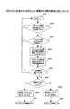
以下、図4−6に示すフローチャートを用いて、通信システムの動作例を説明する。まず、クライアントが行う接続の処理を示すフローチャートを説明し、次に、アクセスポイントが行う処理を示すフローチャートを2通り説明する。<Operation example>
Hereinafter, an operation example of the communication system will be described with reference to the flowchart shown in FIG. First, a flowchart showing a connection process performed by the client will be described, and then two flowcharts showing a process performed by the access point will be described.
〈クライアントの動作(処理)例〉
図4は、クライアントが未接続の状態から、アクセスポイントと接続を確立するまでの手順を示すフローチャートである。<Example of client operation (processing)>
FIG. 4 is a flowchart showing a procedure from when the client is not connected until the connection with the access point is established.
図4に示す処理の開始時点では、クライアントは非接続状態にある(S1)。クライアントは、接続先のSSIDを含む探索パケット(Probe Request)をブロードキャストす
る(S2)。ここで、SSIDは、クライアントがサービスを受けようとしているアクセスポイントを識別するために使用される。At the start of the processing shown in FIG. 4, the client is in a disconnected state (S1). The client broadcasts a search packet (Probe Request) including the SSID of the connection destination (S2). Here, the SSID is used to identify an access point where the client is about to receive a service.
クライアントは、一定時間、アクセスポイントからの応答を受け付ける(S3)。クライアントは、その一定時間内に、最低一つのアクセスポイントから探索パケットに対する探索応答パケットを受信したかを判定する(S4)。 The client receives a response from the access point for a certain time (S3). The client determines whether a search response packet for the search packet has been received from at least one access point within the predetermined time (S4).
クライアントは、探索応答パケット(Probe Response)を一つも受信しなければ、他の無線チャンネルでアクセスポイントを探すために、無線チャンネルを変更する(S5)。そして、処理が、ステップS2に戻る。 If no search response packet (Probe Response) is received, the client changes the radio channel in order to search for an access point on another radio channel (S5). Then, the process returns to step S2.
S4のステップで、クライアントが一つ以上の探索応答パケットを受信していれば、クライアントは、アクセスポイントからの信号強度が最も強いアクセスポイントを、接続先のアクセスポイントとして選定する(S6)。 If the client has received one or more search response packets in step S4, the client selects an access point having the strongest signal strength from the access point as a connection destination access point (S6).
クライアントは、選定したアクセスポイントに対して、接続手順を開始する(S7)。そして、クライアントは、アクセスポイントとの接続に成功したか否かを判定する(S8)。 The client starts a connection procedure for the selected access point (S7). Then, the client determines whether or not the connection with the access point is successful (S8).
アクセスポイントとの接続に失敗すれば(S8;No)、クライアントの処理は、ステップS2に戻る。また、クライアントがアクセスポイントとの接続に成功すれば(S8;Y
es)、クライアントとアクセスポイントとの間での接続状態が確立される(S9)。If the connection with the access point fails (S8; No), the client process returns to step S2. If the client successfully connects to the access point (S8; Y
es), the connection state between the client and the access point is established (S9).
以上の処理により、クライアントは、探索応答パケットを受信した複数のアクセスポイントから、無線通信の状態が良好なアクセスポイントを選択して接続することができる。 Through the above processing, the client can select and connect an access point with a good wireless communication state from a plurality of access points that have received the search response packet.
〈アクセスポイントの動作(処理)例1〉
図5は、アクセスポイントが、自アクセスポイントに接続するクライアントを他のアクセスポイントに切り替える処理(クライアントの移動元のアクセスポイント装置の処理)を示すフローチャートである。<Access point operation (processing) example 1>
FIG. 5 is a flowchart showing processing (processing of the access point device from which the client is moved) in which the access point switches the client connected to the own access point to another access point.
最初に、中央処理装置2は、定期的に、自アクセスポイントに接続するクライアントによる負荷を計算する(S10)。負荷として、例えば、中央処理装置2(図2)のCPU負荷や、自アクセスポイントに接続するクライアントの台数が算出される。 First, the
次に、中央処理装置2は、負荷の計算結果を基に、自アクセスポイントに接続するクライアントを他のアクセスポイントへ移動させるかを判定する(S11)。ここでの判定は、負荷の計算結果が、アクセスポイントに予め備える所定の値より大きいか否かの判定としてなされる。例えば、中央処理装置2は、CPU負荷が所定値を上回っている場合(中央処理装置2が「自サービス装置の負荷が所定値以上であることが検知された場合」に相当)や、クライアントの台数が所定値以上の場合(中央処理装置2が本発明の「自サービス装置に接続されるクライアント装置の数が所定値以上であることが検知された場合」に相当する)に、クライアントの一つを移動すべきと判定する。 Next, the
次に、中央処理装置2は、自アクセスポイントに接続中のクライアントから、どのクライアントを他のアクセスポイントに移動させるかを選定する(中央処理装置2が本発明の「選択手段」に相当する)(S12)。ここで、中央処理装置2は、クライアントからの信号強度が最も弱いクライアントを移動対象のクライアントとして選定する(中央処理装置2が本発明の「受信強度が最も弱いクライアント装置を選択する」に相当する)。このとき、信号強度が弱いという条件のみではなく、クライアントの負荷(例えば、クライア
ントからの単位時間あたりのデータ量)の大きさをも考慮して、当該のクライアントを算
出してもよい。Next, the
中央処理装置2は、他のアクセスポイントへ移動させないと判定した場合、処理をS10に戻す。また、中央処理装置2は、他のアクセスポイントへ移動させると判定した場合、問い合わせパケットを作成し、有線LANインターフェース部4を通じて、サブネットワークにブロードキャストする(S13)。問い合わせパケットは、選定されたクライアントの他のアクセスポイントにおける信号の強度と、そのアクセスポイントにおける負荷を問い合わせるために使用される。 If the
中央処理装置2は、所定時間内に、問い合わせパケットに対する返信パケットを有線LANインターフェース部4で受信したかを判定する(S14)。ここで、返信パケット(本発明の「返信」に相当)は、返信パケットの送出を行ったアクセスポイントのMACアドレス、送信パケットの送出を行ったアクセスポイントでの選定されたクライアントの受信信号強度が含まれている。返信パケットを受信する有線LANインターフェース部4が本発明の「受信手段」に相当する。 The
中央処理装置2が返信パケットを受信していないと判定する場合(S14;No)では、他のアクセスポイントも自アクセスポイントと同様に負荷が高く、他のクライアントを受け入れられない状態であると考えられる。その場合、中央処理装置2は、処理をステップS10に戻す。 When the
また、中央処理装置2は、所定時間内に、返信パケットを受信したならば(S14;Y
es)、クライアントの移動先となるアクセスポイントを選定する。この選定は、返信パ
ケット内に含まれる情報に基づいて選定する。すなわち、中央処理装置2は、それぞれのアクセスポイントでの負荷と、それぞれのアクセスポイントでの選定されたクライアントの受信信号の強度から移動先のアクセスポイントを選定する(中央処理装置2が本発明の「決定手段」に相当する)(S15)。If the
es), and select the access point that the client will move to. This selection is made based on information included in the reply packet. That is, the
そして、中央処理装置2は、選定されたアクセスポイントを他のアクセスポイントに通
知するための通知パケットを作成し、有線LANインターフェース部4を通じてサブネットワーク内にブロードキャストする(有線LANインターフェース部4が本発明の「制御情報をネットワークを通じて他のサービス装置に送信する手段」に相当する)(S16)。通知パケットには、選定されたクライアントと、選定されたアクセスポイントの情報が含まれている。Then, the
そして、クライアントからの接続を切断するために、中央処理装置2は、一定の期間、選定されたクライアントからの探索パケットを受けても、探索応答パケットを返信しないよう処理する(中央処理装置2が本発明の「一定期間抑止する手段」に相当する)(S17)。クライアントは、一定期間、探索パケットに対する応答がないと、接続を切断する。したがって、選定されたクライアントからの接続が切れる(S18)。 Then, in order to disconnect the connection from the client, the
以上の処理により、アクセスポイントに接続しているクライアントが負荷になっている場合、他のアクセスポイントに当該のクライアントを移動させることができる。 With the above processing, when a client connected to an access point is under load, the client can be moved to another access point.
〈アクセスポイントの動作(処理)例2〉
図6は、アクセスポイントが問い合わせパケットを受信し、所定の条件によって、他のアクセスポイントに接続するクライアントを自アクセスポイントに接続する処理(クライ
アントの移動元のアクセスポイント以外のアクセスポイント装置の処理)を示すフローチ
ャートである。<Access point operation (processing) example 2>
FIG. 6 shows a process in which an access point receives an inquiry packet and connects a client connected to another access point to its own access point according to a predetermined condition (process of an access point device other than the access point of the client movement source). It is a flowchart which shows.
図6に示す処理の開始時点では、中央処理装置2は、他のアクセスポイントから何らかのパケットを受信可能な状態である(S19)。中央処理装置2は、何らかのパケットを受信した際、それが問い合わせパケットかを判定する(S20)。受信したパケットが問い合わせパケットでない場合には、処理がS19に戻る。 At the start of the process shown in FIG. 6, the
中央処理装置2は、受信したパケットが問い合わせパケットであると判定した場合、自アクセスポイントがクライアントを受け入れられる状態であるかを判定する(S21)。中央処理装置2は、クライアントを受け入れる余裕がないと判定した場合、処理をステップS19に戻す。 When the
中央処理装置2は、自アクセスポイントがクライアントを受け入れられる状態であると判定した場合、問い合わせパケットに含まれているクライアントに対して、自アクセスポイントが受信する信号強度を測定する。さらに、中央処理装置2は、ランダムアクセスメモリ1に登録されている自アクセスポイントに接続しているクライアント情報から自アクセスポイントの負荷を算出する(S22)。 When the
中央処理装置2は、その負荷と信号強度の情報とを含む返信パケットを生成し、問い合わせパケットの送信元のアクセスポイントへ宛てて、有線LANインターフェース部4からサブネットワークへ送出する(S23)。 The
中央処理装置2は、一定時間、問い合わせパケットの送信元のアクセスポイントからの通知パケットの受信を待つ。そして、中央処理装置2は、一定時間内に通知パケットを受信したかを判定する(S24)。中央処理装置2は、一定時間内に、通知パケットを受信していなければ(S24;No)、処理をステップS19に戻す。 The
中央処理装置2は、一定時間内に通知パケットを受信していれば(S24;Yes)、通知パケットで指定される移動先のアクセスポイントが自アクセスポイントであるかを判定する(S25)。 If the
このとき、通知パケットで指定される移動先のアクセスポイントが自アクセスポイントでなければ(S25;No)、中央処理装置2は、一定期間、移動対象のクライアントからの探索パケットに応答しない(中央処理装置2が本発明の「選択されたクライアント装置からの探索要求に対して接続可能を示す応答の送信を一定期間抑止する手段」に相当する)(S26)。一定期間、クライアントからの探索パケットに応答しないことにより、自アクセスポイントは少なくとも移動対象のクライアントと接続されない(S27)。 At this time, if the destination access point designated by the notification packet is not its own access point (S25; No), the
通知パケットで指定された移動先のアクセスポイントが自アクセスポイントであった場合(S25;Yes)には、中央処理装置2は、クライアントからの探索パケットに応答する(S28)。これによって、移動対象のクライアントからの探索パケットに応答することができ、その後に当該クライアントから送信されてくる接続要求を受け付けて当該クライアントとの接続手順を行うことができる(S29)。 If the destination access point specified in the notification packet is the local access point (S25; Yes), the
以上の処理により、クライアントを受け入れることができるアクセスポイントの中から、アクセスポイントとクライアントとの間の無線通信の状態と、アクセスポイントの負荷の状態とで選定されたアクセスポイントが、当該のクライアントを受け入れることにより、アクセスポイント全体の負荷を分散することができる。 Through the above processing, the access point selected from the access points that can accept the client based on the state of wireless communication between the access point and the client and the state of the load of the access point determines that client. By accepting, the load of the entire access point can be distributed.
上記したステップS26及びS28の処理は、移動対象のクライアントからの探索パケットに対してのみ実行されるようにしても良い。 The processes in steps S26 and S28 described above may be executed only for the search packet from the client to be moved.
《実施形態の作用効果》
以上説明した実施形態の作用効果を、図1に示す通信システムを用いて説明する。アクセスポイントAは、各クライアントa,b及びcと接続している状態において、負荷が上昇(例えば、中央処理装置2のCPU負荷が所定値を超える)すると、各クライアントa,b,cから、移動対象のクライアントを選定する。ここでは、クライアントcからの電波の受信信号強度が最も弱いので、クライアントcを移動対象として選定する。<< Effects of Embodiment >>
The operational effects of the embodiment described above will be described using the communication system shown in FIG. In a state where the access point A is connected to each of the clients a, b, and c, when the load increases (for example, the CPU load of the
次に、アクセスポイントAは、サブネットワークへ問い合わせパケットをブロードキャストする。問い合わせパケットは、アクセスポイントB及びアクセスポイントCによって受信される。各アクセスポイントB及びアクセスポイントCは、クライアントcからの探索パケットの受信信号強度を測定し、少なくともその測定結果(信号強度)と、アクセスポイントの負荷情報を含む返信パケットを、サブネットワークを通じてアクセスポイントAに送信する。 Next, the access point A broadcasts an inquiry packet to the subnetwork. The inquiry packet is received by the access point B and the access point C. Each access point B and access point C measure the received signal strength of the search packet from the client c, and send a return packet including at least the measurement result (signal strength) and load information of the access point through the subnetwork. Send to A.
アクセスポイントAは、一定時間内に返信パケットを受信すると、返信パケットの送信元のアクセスポイントから、移動先のアクセスポイントを決定する。例えば、アクセスポイントAは、アクセスポイントB及びアクセスポイントCから返信パケットを受信した場合には、各返信パケットに含まれた信号強度を比較する。アクセスポイントBからの返信パケット中の信号強度が最も高い場合には、アクセスポイントBを移動先のアクセスポイントとして決定する。このとき、アクセスポイントAは、返信パケットに含まれた負荷情報をアクセスポイントの決定の条件として考慮することができる。 When the access point A receives the reply packet within a certain time, the access point A determines the destination access point from the access point that is the source of the reply packet. For example, when receiving a reply packet from the access point B and the access point C, the access point A compares the signal strength included in each reply packet. When the signal strength in the reply packet from the access point B is the highest, the access point B is determined as the destination access point. At this time, the access point A can consider the load information included in the reply packet as a condition for determining the access point.
アクセスポイントAは、アクセスポイントB及びアクセスポイントCに、アクセスポイントBが移動先(新たな接続先)として決定されたことを示す通知パケットを、サブネットワークを通じてブロードキャストする。これによって、通知パケットがアクセスポイントB及びアクセスポイントCに届く。 The access point A broadcasts to the access point B and the access point C a notification packet indicating that the access point B is determined as a movement destination (new connection destination) through the subnetwork. As a result, the notification packet reaches the access point B and the access point C.
その後、アクセスポイントAは、一定期間、クライアントcからの探索パケットに応答しない。また、アクセスポイントCは、通知パケットの受信により、アクセスポイントB
がクライアントcの移動先として決定されたことを知ると、一定期間、クライアントからの探索パケットに応答しない。一方、アクセスポイントBは、通知パケットの受信により、自身がクライアントcの移動先として決定されたことを知ると、探索パケットに対して応答する状態を継続する。Thereafter, the access point A does not respond to the search packet from the client c for a certain period. In addition, the access point C receives the notification packet and receives the access point B.
Is determined as the destination of the client c, it does not respond to the search packet from the client for a certain period. On the other hand, when the access point B knows that it has been determined as the destination of the client c by receiving the notification packet, the access point B continues to respond to the search packet.
従って、クライアントcからの探索パケットに対し、移動先として決定されたアクセスポイントBしか応答しない状態となる。即ち、クライアントcは、アクセスポイントBのみから探索応答パケットを受信する状態となる。これによって、クライアントcは、接続先をアクセスポイントAからアクセスポイントBへ切り替える手順を実行する。このようにして、クライアントcの接続先がアクセスポイントAからアクセスポイントBに切り替わる。 Therefore, only the access point B determined as the movement destination responds to the search packet from the client c. That is, the client c is in a state of receiving a search response packet from only the access point B. As a result, the client c executes a procedure for switching the connection destination from the access point A to the access point B. In this way, the connection destination of the client c is switched from the access point A to the access point B.
本実施形態によれば、上述した動作によって、クライアントに実装された探索応答パケットの受信信号強度に基づくアクセスポイントの選定手法によって、1つのアクセスポイントに複数のクライアントが集中しても、複数のクライアントの一つを、そのクライアントが接続可能な(共通のSSIDを持つ)他のアクセスポイントに強制的に移動させることができる。これによって、クライアントの接続先の分散を図ることができる。また、移動元のアクセスポイントの負荷軽減、1台あたりの利用可能帯域(スループット)の低下を抑止することができる。 According to the present embodiment, even if a plurality of clients are concentrated on one access point by the above-described operation, even if a plurality of clients are concentrated on one access point by the access point selection method based on the received signal strength of the search response packet mounted on the client, Can be forcibly moved to another access point to which the client can connect (having a common SSID). As a result, the connection destinations of clients can be distributed. In addition, it is possible to reduce the load on the access point at the movement source and to suppress a decrease in available bandwidth (throughput) per device.
また、本実施形態によれば、問い合わせパケットを受信したアクセスポイントは、クライアントを受け入れ可能か否かを判定し、そうでなければ返信パケットを送信しない。これによって、返信パケットを送信しないアクセスポイントが移動先の候補から除外される。従って、移動元のアクセスポイントは、クライアントを受け入れ可能な他のアクセスポイントから、移動先のアクセスポイントを選定することができる。 Further, according to the present embodiment, the access point that has received the inquiry packet determines whether or not the client can be accepted, and otherwise does not transmit a reply packet. As a result, access points that do not transmit a reply packet are excluded from destination candidates. Therefore, the movement-source access point can select the movement-destination access point from other access points that can accept the client.
また、本実施形態によれば、移動元のアクセスポイントにおいて、返信パケットに含まれた信号強度,又は信号強度及び負荷から、良好な通信品質(例えば、現状の通信品質と
同等、あるいはそれ以上の通信品質)を確保できるアクセスポイントを、移動先のアクセ
スポイントとして選定することができる。これによって、アクセスポイントの切り替えが実施されても、移動対象のクライアントは、或る程度の(良好な)通信品質を、移動先のアクセスポイントとの通信において確保することができる。Further, according to the present embodiment, at the access point of the movement source, good communication quality (for example, equal to or higher than the current communication quality) is obtained from the signal strength included in the reply packet, or the signal strength and load. An access point that can ensure (communication quality) can be selected as a destination access point. As a result, even when the access point is switched, the client to be moved can ensure a certain level of (good) communication quality in communication with the access point of the movement destination.
さらに、上述した実施形態では、クライアント(端末)について、上記した動作を行うための構成の変更や追加を必要としない。即ち、従来におけるクライアントをそのまま利用することができる。従って、実施形態に係る通信システムの導入に必要なコストを抑えることができる。 Further, in the above-described embodiment, it is not necessary to change or add a configuration for performing the above-described operation for the client (terminal). That is, a conventional client can be used as it is. Therefore, the cost required for introducing the communication system according to the embodiment can be suppressed.
A,B,C アクセスポイント
a,b,c クライアント(無線LANクライアント)
1 ランダムアクセスメモリ(RAM)
2 中央処理装置(CPU)
3 フラッシュロム(Flash ROM)
4 有線LANインターフェース部
5 無線LANインターフェース部
6 ベースバンドプロセッサ
7 トランシーバ
8 電力増幅器
9 アンテナ
10 イーサネット(Ethernet)(登録商標)ヘッダ
11 IPヘッダ
12 UDPヘッダ
13 データ部A, B, C Access points a, b, c Client (wireless LAN client)
1 Random access memory (RAM)
2 Central processing unit (CPU)
3 Flash ROM
4 wired
Claims (11)
Translated fromJapanese所定状態が検知されたときに接続を切り離すべきクライアント装置を選択する選択手段と、
ネットワークを通じて接続された他のサービス装置に対して、該選択されたクライアント装置からの探索要求に対して接続可能を示す応答を依頼する手段と、
前記選択されたクライアント装置から探索要求を受け取った場合、該選択されたクライアント装置に対して接続可能を示す応答の送信を一定期間抑止する手段と
を含むサービス装置。A response is returned to a search request from an unconnected client device, a wireless connection procedure is executed with the client device, and a response is returned to a search request from a connected client device. A service device that provides a wireless connection service to a client device that maintains a connection state with the client device,
Selecting means for selecting a client device to be disconnected when a predetermined state is detected;
Means for requesting a response indicating that connection is possible in response to a search request from the selected client device to another service device connected through the network;
A service device including means for suppressing a transmission of a response indicatingthat the selected client device can be connected for a certain periodwhen a search request is received from the selected client device.
前記他のサービス装置における状態の問い合わせを送信する手段と、
前記問い合わせに応じた他のサービス装置から、該他のサービス装置における状態を示す状態情報を含む返信を、ネットワークを通じて受信する受信手段と、
受信された返信に含まれる状態情報に基づいて、該返信の送信元の他のサービス装置から、前記選択されたクライアント装置の新たな接続先となるべき他のサービス装置を決定する決定手段と、
前記決定された他のサービス装置の識別情報と、前記選択されたクライアント装置の識別情報とを含む、前記決定された他のサービス装置が前記選択されたクライアント装置からの探索要求に応答するとともに、前記決定された他のサービス装置以外の他のサービス装置が前記選択されたクライアント装置からの探索要求に対して接続可能を示す応答の送信を一定期間抑止するための制御情報を、ネットワークを通じて他のサービス装置に送信する手段と、
からなる請求項1記載のサービス装置。A means for requesting a response indicating that connection is possible in response to a search request from the selected client device,
Means for transmitting a status inquiry in the other service device;
Receiving means for receiving, via a network, a reply including status information indicating the status of the other service device from another service device in response to the inquiry;
Determining means for determining, based on the status information included in the received reply, other service devices to be a new connection destination of the selected client device from other service devices of the reply transmission source;
The determined other service device responding to a search request from the selected client device, including identification information of the determined other service device and identification information of the selected client device; Control information for suppressing transmission of a response indicating that a service device other than the determined other service device can connect to the search request from the selected client device for a certain period of time Means for transmitting to the service device;
The service device according to claim 1, comprising:
信信号強度を含み、
前記決定手段は、受信信号強度が最も強い他のサービス装置を前記クライアント装置の移動先として決定する
請求項2記載のサービス装置。The status information includes received signal strength from the selected client device in another service device,
The service apparatus according to claim 2, wherein the determination unit determines another service apparatus having thestrongest received signal strength as a destination of the client apparatus.
前記決定手段は、前記受信信号強度及び前記処理負荷に基づいて、前記クライアント装置の移動先となる他のサービス装置を決定する
請求項3記載のサービス装置。The status information further includes information indicating a processing load in another service device,
The service apparatus according to claim 3, wherein the determination unit determines another service apparatus that is a destination of the client apparatus based on the received signal strength and the processing load.
前記クライアント装置が未接続である場合に、前記クライアント装置を当該サービス装置に接続可能か否かを判定する手段とをさらに備え、
前記クライアント装置を接続できない場合に、前記問い合わせが他のサービス装置に対して実行される請求項2〜5のいずれか1項に記載のサービス装置。Means for determining whether or not the client device that has transmitted the search request is not connected to the own service device;
Means for determining whether or not the client device can be connected to the service device when the client device is not connected;
If you can not connect the client device, the inquiry service device according to anyone ofclaims 2-5 to be performed on other service devices.
前記サービス装置が、
所定状態が検知されたときに接続を切り離すべきクライアント装置を選択し、
ネットワークを通じて接続された他のサービス装置に対して、該選択されたクライアント装置からの探索要求に対して接続可能を示す応答を依頼し、
前記選択されたクライアント装置から探索要求を受け取った場合、該選択されたクライアント装置に対して接続可能を示す応答の送信を一定期間停止する
ことを含むクライアント装置の接続先切替制御方法。A response is returned to a search request from an unconnected client device, a wireless connection procedure is executed with the client device, and a response is returned to a search request from a connected client device. A connection destination switching control method of a client device by a service device included in a service device group that provides a wireless connection service to the client device that continues the connection state with the client device,
The service device is
Select the client device that should be disconnected when a certain condition is detected,
Requests a response indicating that connection is possible in response to a search request from the selected client device to another service device connected through the network,
A connection destination switching control method for a client device, comprising:when a search request is received from the selected client device, stopping transmission of a response indicatingthat connection is possiblefor the selected client device for a certain period of time.
装置に無線接続サービスを提供するサービス装置群に含まれるサービス装置に、クライアント装置の接続先切替制御を行わせるためのプログラムであって、
所定状態が検知されたときに接続を切り離すべきクライアント装置を選択するステップと、
ネットワークを通じて接続された他のサービス装置に対して、該選択されたクライアント装置からの探索要求に対して接続可能を示す応答を依頼するステップと、
前記選択されたクライアント装置から探索要求を受け取った場合、該選択されたクライアント装置に対して接続可能を示す応答の送信を一定期間停止するステップと
を含むプログラム。A response is returned to a search request from an unconnected client device, a wireless connection procedure is executed with the client device, and a response is returned to a search request from a connected client device. A program for causing a service device included in a service device group that provides a wireless connection service to a client device to continue a connection state with the client device, and to perform connection destination switching control of the client device,
Selecting a client device to be disconnected when a predetermined condition is detected;
Requesting another service device connected through the network for a response indicating that connection is possible in response to a search request from the selected client device;
And a step of stopping transmission of a response indicatingthat connection is possiblefor the selected client device for a certain periodwhen a search request is received from the selected client device .
Priority Applications (5)
| Application Number | Priority Date | Filing Date | Title |
|---|---|---|---|
| JP2005102449AJP4630706B2 (en) | 2005-03-31 | 2005-03-31 | Service device, client device connection destination switching control method and program by service device |
| DE102005038445.5ADE102005038445B4 (en) | 2005-03-31 | 2005-08-12 | A service device, method for controlling switching of the connection destination of the client device by the service device and machine-readable storage medium |
| KR1020050078098AKR100703018B1 (en) | 2005-03-31 | 2005-08-25 | Method of controlling connection destination switching of client apparatus by service apparatus, service apparatus and storage medium |
| CNA2005100991471ACN1842038A (en) | 2005-03-31 | 2005-09-02 | Server device, client connection destination switching control method, and readable storage medium |
| US11/239,065US8014355B2 (en) | 2005-03-31 | 2005-09-30 | Service apparatus, method of controlling switching of connection destination of client apparatus by service apparatus, and storage medium readable by machine |
Applications Claiming Priority (1)
| Application Number | Priority Date | Filing Date | Title |
|---|---|---|---|
| JP2005102449AJP4630706B2 (en) | 2005-03-31 | 2005-03-31 | Service device, client device connection destination switching control method and program by service device |
Publications (2)
| Publication Number | Publication Date |
|---|---|
| JP2006287426A JP2006287426A (en) | 2006-10-19 |
| JP4630706B2true JP4630706B2 (en) | 2011-02-09 |
Family
ID=36999048
Family Applications (1)
| Application Number | Title | Priority Date | Filing Date |
|---|---|---|---|
| JP2005102449AExpired - Fee RelatedJP4630706B2 (en) | 2005-03-31 | 2005-03-31 | Service device, client device connection destination switching control method and program by service device |
Country Status (5)
| Country | Link |
|---|---|
| US (1) | US8014355B2 (en) |
| JP (1) | JP4630706B2 (en) |
| KR (1) | KR100703018B1 (en) |
| CN (1) | CN1842038A (en) |
| DE (1) | DE102005038445B4 (en) |
Families Citing this family (195)
| Publication number | Priority date | Publication date | Assignee | Title |
|---|---|---|---|---|
| US8528086B1 (en) | 2004-04-01 | 2013-09-03 | Fireeye, Inc. | System and method of detecting computer worms |
| US8898788B1 (en) | 2004-04-01 | 2014-11-25 | Fireeye, Inc. | Systems and methods for malware attack prevention |
| US7587537B1 (en) | 2007-11-30 | 2009-09-08 | Altera Corporation | Serializer-deserializer circuits formed from input-output circuit registers |
| US8549638B2 (en) | 2004-06-14 | 2013-10-01 | Fireeye, Inc. | System and method of containing computer worms |
| US8881282B1 (en) | 2004-04-01 | 2014-11-04 | Fireeye, Inc. | Systems and methods for malware attack detection and identification |
| US8584239B2 (en) | 2004-04-01 | 2013-11-12 | Fireeye, Inc. | Virtual machine with dynamic data flow analysis |
| US8793787B2 (en) | 2004-04-01 | 2014-07-29 | Fireeye, Inc. | Detecting malicious network content using virtual environment components |
| US8171553B2 (en) | 2004-04-01 | 2012-05-01 | Fireeye, Inc. | Heuristic based capture with replay to virtual machine |
| US9106694B2 (en) | 2004-04-01 | 2015-08-11 | Fireeye, Inc. | Electronic message analysis for malware detection |
| US8566946B1 (en) | 2006-04-20 | 2013-10-22 | Fireeye, Inc. | Malware containment on connection |
| US9027135B1 (en) | 2004-04-01 | 2015-05-05 | Fireeye, Inc. | Prospective client identification using malware attack detection |
| US20070076632A1 (en)* | 2005-10-05 | 2007-04-05 | Hewlett-Packard Development Company, L.P. | Network port for tracing a connection topology |
| US8681691B2 (en)* | 2007-07-25 | 2014-03-25 | Microsoft Corporation | Base station initiated proximity service discovery and connection establishment |
| US8644206B2 (en) | 2007-08-17 | 2014-02-04 | Qualcomm Incorporated | Ad hoc service provider configuration for broadcasting service information |
| US20090047930A1 (en)* | 2007-08-17 | 2009-02-19 | Qualcomm Incorporated | Method for a heterogeneous wireless ad hoc mobile service provider |
| US20090047964A1 (en) | 2007-08-17 | 2009-02-19 | Qualcomm Incorporated | Handoff in ad-hoc mobile broadband networks |
| KR20090044740A (en)* | 2007-11-01 | 2009-05-07 | 삼성전자주식회사 | Apparatus and method for changing access point in wireless network system |
| JP2009118898A (en) | 2007-11-12 | 2009-06-04 | Hoya Corp | Endoscope processor and endoscope system |
| US8850571B2 (en) | 2008-11-03 | 2014-09-30 | Fireeye, Inc. | Systems and methods for detecting malicious network content |
| US8997219B2 (en) | 2008-11-03 | 2015-03-31 | Fireeye, Inc. | Systems and methods for detecting malicious PDF network content |
| US9538355B2 (en) | 2008-12-29 | 2017-01-03 | Google Technology Holdings LLC | Method of targeted discovery of devices in a network |
| US9148423B2 (en) | 2008-12-29 | 2015-09-29 | Google Technology Holdings LLC | Personal identification number (PIN) generation between two devices in a network |
| US8504836B2 (en) | 2008-12-29 | 2013-08-06 | Motorola Mobility Llc | Secure and efficient domain key distribution for device registration |
| US9179367B2 (en) | 2009-05-26 | 2015-11-03 | Qualcomm Incorporated | Maximizing service provider utility in a heterogeneous wireless ad-hoc network |
| US8904172B2 (en) | 2009-06-17 | 2014-12-02 | Motorola Mobility Llc | Communicating a device descriptor between two devices when registering onto a network |
| GB2489553B (en) | 2009-08-11 | 2013-01-30 | Ubiquisys Ltd | Load balancing in a mobile communication network |
| US8832829B2 (en) | 2009-09-30 | 2014-09-09 | Fireeye, Inc. | Network-based binary file extraction and analysis for malware detection |
| CN101808119A (en)* | 2010-03-04 | 2010-08-18 | 杭州华三通信技术有限公司 | Method and equipment for multiple storage array load balancing |
| US20110274029A1 (en)* | 2010-05-10 | 2011-11-10 | Comcast Cable Communications, Llc | Wireless Range Extender |
| US8321503B2 (en)* | 2010-06-24 | 2012-11-27 | Microsoft Corporation | Context-specific network resource addressing model for distributed services |
| JP5234121B2 (en)* | 2011-01-28 | 2013-07-10 | ブラザー工業株式会社 | Karaoke network system and wireless communication terminal |
| US9408177B2 (en) | 2011-12-19 | 2016-08-02 | Cisco Technology, Inc. | System and method for resource management for operator services and internet |
| US9210728B2 (en)* | 2011-12-19 | 2015-12-08 | Cisco Technology, Inc. | System and method for resource management for operator services and internet |
| US9137171B2 (en) | 2011-12-19 | 2015-09-15 | Cisco Technology, Inc. | System and method for resource management for operator services and internet |
| US9519782B2 (en) | 2012-02-24 | 2016-12-13 | Fireeye, Inc. | Detecting malicious network content |
| US8565793B1 (en) | 2012-05-15 | 2013-10-22 | Cisco Technology, Inc. | System and method for scoped paging in multi-radio heterogeneous networks |
| US9661522B2 (en) | 2012-07-09 | 2017-05-23 | Cisco Technology, Inc. | System and method associated with a service flow router |
| EP2916589B1 (en)* | 2012-11-30 | 2018-08-22 | Huawei Technologies Co., Ltd. | Migration method and device |
| US10572665B2 (en) | 2012-12-28 | 2020-02-25 | Fireeye, Inc. | System and method to create a number of breakpoints in a virtual machine via virtual machine trapping events |
| US9367681B1 (en) | 2013-02-23 | 2016-06-14 | Fireeye, Inc. | Framework for efficient security coverage of mobile software applications using symbolic execution to reach regions of interest within an application |
| US9176843B1 (en) | 2013-02-23 | 2015-11-03 | Fireeye, Inc. | Framework for efficient security coverage of mobile software applications |
| US9009822B1 (en) | 2013-02-23 | 2015-04-14 | Fireeye, Inc. | Framework for multi-phase analysis of mobile applications |
| US9159035B1 (en) | 2013-02-23 | 2015-10-13 | Fireeye, Inc. | Framework for computer application analysis of sensitive information tracking |
| US9824209B1 (en) | 2013-02-23 | 2017-11-21 | Fireeye, Inc. | Framework for efficient security coverage of mobile software applications that is usable to harden in the field code |
| US8990944B1 (en) | 2013-02-23 | 2015-03-24 | Fireeye, Inc. | Systems and methods for automatically detecting backdoors |
| US9195829B1 (en) | 2013-02-23 | 2015-11-24 | Fireeye, Inc. | User interface with real-time visual playback along with synchronous textual analysis log display and event/time index for anomalous behavior detection in applications |
| US9009823B1 (en) | 2013-02-23 | 2015-04-14 | Fireeye, Inc. | Framework for efficient security coverage of mobile software applications installed on mobile devices |
| US9355247B1 (en) | 2013-03-13 | 2016-05-31 | Fireeye, Inc. | File extraction from memory dump for malicious content analysis |
| US9104867B1 (en) | 2013-03-13 | 2015-08-11 | Fireeye, Inc. | Malicious content analysis using simulated user interaction without user involvement |
| US9565202B1 (en) | 2013-03-13 | 2017-02-07 | Fireeye, Inc. | System and method for detecting exfiltration content |
| US9626509B1 (en) | 2013-03-13 | 2017-04-18 | Fireeye, Inc. | Malicious content analysis with multi-version application support within single operating environment |
| US9311479B1 (en) | 2013-03-14 | 2016-04-12 | Fireeye, Inc. | Correlation and consolidation of analytic data for holistic view of a malware attack |
| US9430646B1 (en) | 2013-03-14 | 2016-08-30 | Fireeye, Inc. | Distributed systems and methods for automatically detecting unknown bots and botnets |
| US10713358B2 (en) | 2013-03-15 | 2020-07-14 | Fireeye, Inc. | System and method to extract and utilize disassembly features to classify software intent |
| US9413781B2 (en) | 2013-03-15 | 2016-08-09 | Fireeye, Inc. | System and method employing structured intelligence to verify and contain threats at endpoints |
| US9251343B1 (en) | 2013-03-15 | 2016-02-02 | Fireeye, Inc. | Detecting bootkits resident on compromised computers |
| US9495180B2 (en) | 2013-05-10 | 2016-11-15 | Fireeye, Inc. | Optimized resource allocation for virtual machines within a malware content detection system |
| US9635039B1 (en) | 2013-05-13 | 2017-04-25 | Fireeye, Inc. | Classifying sets of malicious indicators for detecting command and control communications associated with malware |
| US10133863B2 (en) | 2013-06-24 | 2018-11-20 | Fireeye, Inc. | Zero-day discovery system |
| US9536091B2 (en) | 2013-06-24 | 2017-01-03 | Fireeye, Inc. | System and method for detecting time-bomb malware |
| US9888016B1 (en) | 2013-06-28 | 2018-02-06 | Fireeye, Inc. | System and method for detecting phishing using password prediction |
| US9300686B2 (en) | 2013-06-28 | 2016-03-29 | Fireeye, Inc. | System and method for detecting malicious links in electronic messages |
| US9690936B1 (en) | 2013-09-30 | 2017-06-27 | Fireeye, Inc. | Multistage system and method for analyzing obfuscated content for malware |
| US9628507B2 (en) | 2013-09-30 | 2017-04-18 | Fireeye, Inc. | Advanced persistent threat (APT) detection center |
| US10192052B1 (en) | 2013-09-30 | 2019-01-29 | Fireeye, Inc. | System, apparatus and method for classifying a file as malicious using static scanning |
| US9171160B2 (en) | 2013-09-30 | 2015-10-27 | Fireeye, Inc. | Dynamically adaptive framework and method for classifying malware using intelligent static, emulation, and dynamic analyses |
| US10515214B1 (en) | 2013-09-30 | 2019-12-24 | Fireeye, Inc. | System and method for classifying malware within content created during analysis of a specimen |
| US9294501B2 (en) | 2013-09-30 | 2016-03-22 | Fireeye, Inc. | Fuzzy hash of behavioral results |
| US9736179B2 (en) | 2013-09-30 | 2017-08-15 | Fireeye, Inc. | System, apparatus and method for using malware analysis results to drive adaptive instrumentation of virtual machines to improve exploit detection |
| US10089461B1 (en) | 2013-09-30 | 2018-10-02 | Fireeye, Inc. | Page replacement code injection |
| US9503384B1 (en)* | 2013-10-28 | 2016-11-22 | Thousandeyes, Inc. | Estimating network capacity and network bandwidth without server instrumentation |
| US9921978B1 (en) | 2013-11-08 | 2018-03-20 | Fireeye, Inc. | System and method for enhanced security of storage devices |
| US9189627B1 (en) | 2013-11-21 | 2015-11-17 | Fireeye, Inc. | System, apparatus and method for conducting on-the-fly decryption of encrypted objects for malware detection |
| US9747446B1 (en) | 2013-12-26 | 2017-08-29 | Fireeye, Inc. | System and method for run-time object classification |
| US9756074B2 (en) | 2013-12-26 | 2017-09-05 | Fireeye, Inc. | System and method for IPS and VM-based detection of suspicious objects |
| JP6101197B2 (en)* | 2013-12-27 | 2017-03-22 | 京セラドキュメントソリューションズ株式会社 | Network connection management system and method, and wireless terminal device |
| US9740857B2 (en) | 2014-01-16 | 2017-08-22 | Fireeye, Inc. | Threat-aware microvisor |
| CN104811332B (en)* | 2014-01-29 | 2018-11-02 | 中国移动通信集团广东有限公司 | A kind of optimization method, the apparatus and system in the domains DCN of grouping conveying network PTN |
| US9262635B2 (en) | 2014-02-05 | 2016-02-16 | Fireeye, Inc. | Detection efficacy of virtual machine-based analysis with application specific events |
| US9241010B1 (en) | 2014-03-20 | 2016-01-19 | Fireeye, Inc. | System and method for network behavior detection |
| US10242185B1 (en) | 2014-03-21 | 2019-03-26 | Fireeye, Inc. | Dynamic guest image creation and rollback |
| US9591015B1 (en) | 2014-03-28 | 2017-03-07 | Fireeye, Inc. | System and method for offloading packet processing and static analysis operations |
| US9432389B1 (en) | 2014-03-31 | 2016-08-30 | Fireeye, Inc. | System, apparatus and method for detecting a malicious attack based on static analysis of a multi-flow object |
| US9223972B1 (en) | 2014-03-31 | 2015-12-29 | Fireeye, Inc. | Dynamically remote tuning of a malware content detection system |
| US9438623B1 (en) | 2014-06-06 | 2016-09-06 | Fireeye, Inc. | Computer exploit detection using heap spray pattern matching |
| US9973531B1 (en) | 2014-06-06 | 2018-05-15 | Fireeye, Inc. | Shellcode detection |
| US9594912B1 (en) | 2014-06-06 | 2017-03-14 | Fireeye, Inc. | Return-oriented programming detection |
| US10084813B2 (en) | 2014-06-24 | 2018-09-25 | Fireeye, Inc. | Intrusion prevention and remedy system |
| US9398028B1 (en) | 2014-06-26 | 2016-07-19 | Fireeye, Inc. | System, device and method for detecting a malicious attack based on communcations between remotely hosted virtual machines and malicious web servers |
| US10805340B1 (en) | 2014-06-26 | 2020-10-13 | Fireeye, Inc. | Infection vector and malware tracking with an interactive user display |
| US10002252B2 (en) | 2014-07-01 | 2018-06-19 | Fireeye, Inc. | Verification of trusted threat-aware microvisor |
| JP6023761B2 (en)* | 2014-08-07 | 2016-11-09 | 西日本電信電話株式会社 | Control system, control server, information providing method, and computer program |
| US9363280B1 (en) | 2014-08-22 | 2016-06-07 | Fireeye, Inc. | System and method of detecting delivery of malware using cross-customer data |
| US10671726B1 (en) | 2014-09-22 | 2020-06-02 | Fireeye Inc. | System and method for malware analysis using thread-level event monitoring |
| US9773112B1 (en) | 2014-09-29 | 2017-09-26 | Fireeye, Inc. | Exploit detection of malware and malware families |
| US10027689B1 (en) | 2014-09-29 | 2018-07-17 | Fireeye, Inc. | Interactive infection visualization for improved exploit detection and signature generation for malware and malware families |
| US9877300B2 (en)* | 2014-11-24 | 2018-01-23 | Hewlett Packard Enterprise Development Lp | Determining a location of a disconnected device |
| EP3035741A1 (en)* | 2014-12-17 | 2016-06-22 | Thomson Licensing | WLAN user quality of experience control in a multi-access point environment |
| US9690933B1 (en) | 2014-12-22 | 2017-06-27 | Fireeye, Inc. | Framework for classifying an object as malicious with machine learning for deploying updated predictive models |
| US10075455B2 (en) | 2014-12-26 | 2018-09-11 | Fireeye, Inc. | Zero-day rotating guest image profile |
| US9934376B1 (en) | 2014-12-29 | 2018-04-03 | Fireeye, Inc. | Malware detection appliance architecture |
| US9838417B1 (en) | 2014-12-30 | 2017-12-05 | Fireeye, Inc. | Intelligent context aware user interaction for malware detection |
| US9690606B1 (en) | 2015-03-25 | 2017-06-27 | Fireeye, Inc. | Selective system call monitoring |
| US10148693B2 (en) | 2015-03-25 | 2018-12-04 | Fireeye, Inc. | Exploit detection system |
| US9438613B1 (en) | 2015-03-30 | 2016-09-06 | Fireeye, Inc. | Dynamic content activation for automated analysis of embedded objects |
| US10474813B1 (en) | 2015-03-31 | 2019-11-12 | Fireeye, Inc. | Code injection technique for remediation at an endpoint of a network |
| US9483644B1 (en) | 2015-03-31 | 2016-11-01 | Fireeye, Inc. | Methods for detecting file altering malware in VM based analysis |
| US10417031B2 (en) | 2015-03-31 | 2019-09-17 | Fireeye, Inc. | Selective virtualization for security threat detection |
| US9654485B1 (en) | 2015-04-13 | 2017-05-16 | Fireeye, Inc. | Analytics-based security monitoring system and method |
| US9594904B1 (en) | 2015-04-23 | 2017-03-14 | Fireeye, Inc. | Detecting malware based on reflection |
| US11113086B1 (en) | 2015-06-30 | 2021-09-07 | Fireeye, Inc. | Virtual system and method for securing external network connectivity |
| US10454950B1 (en) | 2015-06-30 | 2019-10-22 | Fireeye, Inc. | Centralized aggregation technique for detecting lateral movement of stealthy cyber-attacks |
| US10726127B1 (en) | 2015-06-30 | 2020-07-28 | Fireeye, Inc. | System and method for protecting a software component running in a virtual machine through virtual interrupts by the virtualization layer |
| US10642753B1 (en) | 2015-06-30 | 2020-05-05 | Fireeye, Inc. | System and method for protecting a software component running in virtual machine using a virtualization layer |
| US10715542B1 (en) | 2015-08-14 | 2020-07-14 | Fireeye, Inc. | Mobile application risk analysis |
| CN105263194A (en)* | 2015-09-18 | 2016-01-20 | 北京金山安全软件有限公司 | Method and device for establishing communication connection between mobile equipment and fixed equipment |
| US10176321B2 (en) | 2015-09-22 | 2019-01-08 | Fireeye, Inc. | Leveraging behavior-based rules for malware family classification |
| US10033747B1 (en) | 2015-09-29 | 2018-07-24 | Fireeye, Inc. | System and method for detecting interpreter-based exploit attacks |
| US10706149B1 (en) | 2015-09-30 | 2020-07-07 | Fireeye, Inc. | Detecting delayed activation malware using a primary controller and plural time controllers |
| US10210329B1 (en) | 2015-09-30 | 2019-02-19 | Fireeye, Inc. | Method to detect application execution hijacking using memory protection |
| US9825976B1 (en) | 2015-09-30 | 2017-11-21 | Fireeye, Inc. | Detection and classification of exploit kits |
| US9825989B1 (en) | 2015-09-30 | 2017-11-21 | Fireeye, Inc. | Cyber attack early warning system |
| US10817606B1 (en) | 2015-09-30 | 2020-10-27 | Fireeye, Inc. | Detecting delayed activation malware using a run-time monitoring agent and time-dilation logic |
| US10601865B1 (en) | 2015-09-30 | 2020-03-24 | Fireeye, Inc. | Detection of credential spearphishing attacks using email analysis |
| US10284575B2 (en) | 2015-11-10 | 2019-05-07 | Fireeye, Inc. | Launcher for setting analysis environment variations for malware detection |
| US10846117B1 (en) | 2015-12-10 | 2020-11-24 | Fireeye, Inc. | Technique for establishing secure communication between host and guest processes of a virtualization architecture |
| US10447728B1 (en) | 2015-12-10 | 2019-10-15 | Fireeye, Inc. | Technique for protecting guest processes using a layered virtualization architecture |
| US10108446B1 (en) | 2015-12-11 | 2018-10-23 | Fireeye, Inc. | Late load technique for deploying a virtualization layer underneath a running operating system |
| US10621338B1 (en) | 2015-12-30 | 2020-04-14 | Fireeye, Inc. | Method to detect forgery and exploits using last branch recording registers |
| US10133866B1 (en) | 2015-12-30 | 2018-11-20 | Fireeye, Inc. | System and method for triggering analysis of an object for malware in response to modification of that object |
| US10050998B1 (en) | 2015-12-30 | 2018-08-14 | Fireeye, Inc. | Malicious message analysis system |
| US10565378B1 (en) | 2015-12-30 | 2020-02-18 | Fireeye, Inc. | Exploit of privilege detection framework |
| US10581874B1 (en) | 2015-12-31 | 2020-03-03 | Fireeye, Inc. | Malware detection system with contextual analysis |
| US9824216B1 (en) | 2015-12-31 | 2017-11-21 | Fireeye, Inc. | Susceptible environment detection system |
| US11552986B1 (en) | 2015-12-31 | 2023-01-10 | Fireeye Security Holdings Us Llc | Cyber-security framework for application of virtual features |
| US10616266B1 (en) | 2016-03-25 | 2020-04-07 | Fireeye, Inc. | Distributed malware detection system and submission workflow thereof |
| US10671721B1 (en) | 2016-03-25 | 2020-06-02 | Fireeye, Inc. | Timeout management services |
| US10601863B1 (en) | 2016-03-25 | 2020-03-24 | Fireeye, Inc. | System and method for managing sensor enrollment |
| US10785255B1 (en) | 2016-03-25 | 2020-09-22 | Fireeye, Inc. | Cluster configuration within a scalable malware detection system |
| US10893059B1 (en) | 2016-03-31 | 2021-01-12 | Fireeye, Inc. | Verification and enhancement using detection systems located at the network periphery and endpoint devices |
| US10826933B1 (en) | 2016-03-31 | 2020-11-03 | Fireeye, Inc. | Technique for verifying exploit/malware at malware detection appliance through correlation with endpoints |
| US10169585B1 (en) | 2016-06-22 | 2019-01-01 | Fireeye, Inc. | System and methods for advanced malware detection through placement of transition events |
| US10462173B1 (en) | 2016-06-30 | 2019-10-29 | Fireeye, Inc. | Malware detection verification and enhancement by coordinating endpoint and malware detection systems |
| JP6325038B2 (en)* | 2016-08-24 | 2018-05-16 | ソフトバンク株式会社 | Radio base station and program |
| US10592678B1 (en) | 2016-09-09 | 2020-03-17 | Fireeye, Inc. | Secure communications between peers using a verified virtual trusted platform module |
| US10491627B1 (en) | 2016-09-29 | 2019-11-26 | Fireeye, Inc. | Advanced malware detection using similarity analysis |
| US10795991B1 (en) | 2016-11-08 | 2020-10-06 | Fireeye, Inc. | Enterprise search |
| US10587647B1 (en) | 2016-11-22 | 2020-03-10 | Fireeye, Inc. | Technique for malware detection capability comparison of network security devices |
| US10581879B1 (en) | 2016-12-22 | 2020-03-03 | Fireeye, Inc. | Enhanced malware detection for generated objects |
| US10552610B1 (en) | 2016-12-22 | 2020-02-04 | Fireeye, Inc. | Adaptive virtual machine snapshot update framework for malware behavioral analysis |
| US10523609B1 (en) | 2016-12-27 | 2019-12-31 | Fireeye, Inc. | Multi-vector malware detection and analysis |
| US10904286B1 (en) | 2017-03-24 | 2021-01-26 | Fireeye, Inc. | Detection of phishing attacks using similarity analysis |
| US10791138B1 (en) | 2017-03-30 | 2020-09-29 | Fireeye, Inc. | Subscription-based malware detection |
| US10554507B1 (en) | 2017-03-30 | 2020-02-04 | Fireeye, Inc. | Multi-level control for enhanced resource and object evaluation management of malware detection system |
| US10902119B1 (en) | 2017-03-30 | 2021-01-26 | Fireeye, Inc. | Data extraction system for malware analysis |
| US10798112B2 (en) | 2017-03-30 | 2020-10-06 | Fireeye, Inc. | Attribute-controlled malware detection |
| US10601848B1 (en) | 2017-06-29 | 2020-03-24 | Fireeye, Inc. | Cyber-security system and method for weak indicator detection and correlation to generate strong indicators |
| US10855700B1 (en) | 2017-06-29 | 2020-12-01 | Fireeye, Inc. | Post-intrusion detection of cyber-attacks during lateral movement within networks |
| US10503904B1 (en) | 2017-06-29 | 2019-12-10 | Fireeye, Inc. | Ransomware detection and mitigation |
| US10893068B1 (en) | 2017-06-30 | 2021-01-12 | Fireeye, Inc. | Ransomware file modification prevention technique |
| US10747872B1 (en) | 2017-09-27 | 2020-08-18 | Fireeye, Inc. | System and method for preventing malware evasion |
| US10805346B2 (en) | 2017-10-01 | 2020-10-13 | Fireeye, Inc. | Phishing attack detection |
| US11108809B2 (en) | 2017-10-27 | 2021-08-31 | Fireeye, Inc. | System and method for analyzing binary code for malware classification using artificial neural network techniques |
| US11240275B1 (en) | 2017-12-28 | 2022-02-01 | Fireeye Security Holdings Us Llc | Platform and method for performing cybersecurity analyses employing an intelligence hub with a modular architecture |
| US11005860B1 (en) | 2017-12-28 | 2021-05-11 | Fireeye, Inc. | Method and system for efficient cybersecurity analysis of endpoint events |
| US11271955B2 (en) | 2017-12-28 | 2022-03-08 | Fireeye Security Holdings Us Llc | Platform and method for retroactive reclassification employing a cybersecurity-based global data store |
| US10826931B1 (en) | 2018-03-29 | 2020-11-03 | Fireeye, Inc. | System and method for predicting and mitigating cybersecurity system misconfigurations |
| US11003773B1 (en) | 2018-03-30 | 2021-05-11 | Fireeye, Inc. | System and method for automatically generating malware detection rule recommendations |
| US10956477B1 (en) | 2018-03-30 | 2021-03-23 | Fireeye, Inc. | System and method for detecting malicious scripts through natural language processing modeling |
| US11558401B1 (en) | 2018-03-30 | 2023-01-17 | Fireeye Security Holdings Us Llc | Multi-vector malware detection data sharing system for improved detection |
| US11314859B1 (en) | 2018-06-27 | 2022-04-26 | FireEye Security Holdings, Inc. | Cyber-security system and method for detecting escalation of privileges within an access token |
| US11075930B1 (en) | 2018-06-27 | 2021-07-27 | Fireeye, Inc. | System and method for detecting repetitive cybersecurity attacks constituting an email campaign |
| US11228491B1 (en) | 2018-06-28 | 2022-01-18 | Fireeye Security Holdings Us Llc | System and method for distributed cluster configuration monitoring and management |
| US11316900B1 (en) | 2018-06-29 | 2022-04-26 | FireEye Security Holdings Inc. | System and method for automatically prioritizing rules for cyber-threat detection and mitigation |
| US11182473B1 (en) | 2018-09-13 | 2021-11-23 | Fireeye Security Holdings Us Llc | System and method for mitigating cyberattacks against processor operability by a guest process |
| US11763004B1 (en) | 2018-09-27 | 2023-09-19 | Fireeye Security Holdings Us Llc | System and method for bootkit detection |
| US11368475B1 (en) | 2018-12-21 | 2022-06-21 | Fireeye Security Holdings Us Llc | System and method for scanning remote services to locate stored objects with malware |
| US11743290B2 (en) | 2018-12-21 | 2023-08-29 | Fireeye Security Holdings Us Llc | System and method for detecting cyberattacks impersonating legitimate sources |
| US12074887B1 (en) | 2018-12-21 | 2024-08-27 | Musarubra Us Llc | System and method for selectively processing content after identification and removal of malicious content |
| US11176251B1 (en) | 2018-12-21 | 2021-11-16 | Fireeye, Inc. | Determining malware via symbolic function hash analysis |
| US11601444B1 (en) | 2018-12-31 | 2023-03-07 | Fireeye Security Holdings Us Llc | Automated system for triage of customer issues |
| US11310238B1 (en) | 2019-03-26 | 2022-04-19 | FireEye Security Holdings, Inc. | System and method for retrieval and analysis of operational data from customer, cloud-hosted virtual resources |
| US11677786B1 (en) | 2019-03-29 | 2023-06-13 | Fireeye Security Holdings Us Llc | System and method for detecting and protecting against cybersecurity attacks on servers |
| US11636198B1 (en) | 2019-03-30 | 2023-04-25 | Fireeye Security Holdings Us Llc | System and method for cybersecurity analyzer update and concurrent management system |
| US10966277B1 (en)* | 2019-06-20 | 2021-03-30 | Amazon Technologies, Inc. | Preventing insider attack in wireless networks |
| US11258806B1 (en) | 2019-06-24 | 2022-02-22 | Mandiant, Inc. | System and method for automatically associating cybersecurity intelligence to cyberthreat actors |
| US11556640B1 (en) | 2019-06-27 | 2023-01-17 | Mandiant, Inc. | Systems and methods for automated cybersecurity analysis of extracted binary string sets |
| US11392700B1 (en) | 2019-06-28 | 2022-07-19 | Fireeye Security Holdings Us Llc | System and method for supporting cross-platform data verification |
| US12200013B2 (en) | 2019-08-07 | 2025-01-14 | Musarubra Us Llc | System and method for detecting cyberattacks impersonating legitimate sources |
| US11886585B1 (en) | 2019-09-27 | 2024-01-30 | Musarubra Us Llc | System and method for identifying and mitigating cyberattacks through malicious position-independent code execution |
| US11637862B1 (en) | 2019-09-30 | 2023-04-25 | Mandiant, Inc. | System and method for surfacing cyber-security threats with a self-learning recommendation engine |
| US11522884B1 (en) | 2019-12-24 | 2022-12-06 | Fireeye Security Holdings Us Llc | Subscription and key management system |
| US11838300B1 (en) | 2019-12-24 | 2023-12-05 | Musarubra Us Llc | Run-time configurable cybersecurity system |
| US11436327B1 (en) | 2019-12-24 | 2022-09-06 | Fireeye Security Holdings Us Llc | System and method for circumventing evasive code for cyberthreat detection |
| US20240381463A1 (en)* | 2021-08-18 | 2024-11-14 | Nippon Telegraph And Telephone Corporation | Wireless connection control method, wireless connection control apparatus and program |
Family Cites Families (31)
| Publication number | Priority date | Publication date | Assignee | Title |
|---|---|---|---|---|
| US4597105A (en)* | 1982-11-12 | 1986-06-24 | Motorola Inc. | Data communications system having overlapping receiver coverage zones |
| JP3197471B2 (en) | 1995-09-28 | 2001-08-13 | 京セラ株式会社 | Base station call connection control method in mobile communication system |
| US6259898B1 (en)* | 1998-05-05 | 2001-07-10 | Telxon Corporation | Multi-communication access point |
| JP2000069050A (en) | 1998-08-24 | 2000-03-03 | Nippon Telegr & Teleph Corp <Ntt> | Centralized control path switching method and radio base station using the method |
| JP2001054165A (en) | 1999-08-04 | 2001-02-23 | Nippon Telegr & Teleph Corp <Ntt> | Data communication device and method, and recording medium |
| JP2001094572A (en) | 1999-09-22 | 2001-04-06 | Clarion Co Ltd | Method for fast roaming in radio lan, access point, and mobile terminal |
| JP2001237856A (en) | 2000-02-23 | 2001-08-31 | Denso Corp | Base station and terminal station applied to radio lan system |
| KR20000058762A (en)* | 2000-06-28 | 2000-10-05 | 김지홍 | Online Wireless User Connection Service |
| JP3550348B2 (en) | 2000-08-18 | 2004-08-04 | 日本電信電話株式会社 | Mobile communication system, central control station and terminal thereof, and communication control method thereof |
| JP2002185458A (en) | 2000-12-13 | 2002-06-28 | Matsushita Electric Ind Co Ltd | Wireless LAN system and terminal |
| US6882677B2 (en)* | 2001-02-28 | 2005-04-19 | Motorola, Inc. | Method and apparatus for facilitating handoff in a wireless local area network |
| WO2002089411A2 (en)* | 2001-05-01 | 2002-11-07 | Koninklijke Philips Electronics N.V. | Handoff in radio communication arrangements |
| JP2003174456A (en) | 2001-12-06 | 2003-06-20 | Matsushita Electric Ind Co Ltd | Wireless LAN system |
| JP3904462B2 (en)* | 2002-02-12 | 2007-04-11 | 株式会社日立製作所 | Wireless communication method and wireless communication system |
| JP2003244167A (en) | 2002-02-21 | 2003-08-29 | Matsushita Electric Ind Co Ltd | Wireless LAN terminal and access point search method |
| US6990343B2 (en)* | 2002-03-14 | 2006-01-24 | Texas Instruments Incorporated | Context block leasing for fast handoffs |
| JP3851587B2 (en) | 2002-04-30 | 2006-11-29 | 松下電器産業株式会社 | Wireless communication terminal device and wireless communication relay device |
| JP4002789B2 (en) | 2002-06-06 | 2007-11-07 | 株式会社エヌ・ティ・ティ・ドコモ | Wireless multicast system, network device, wireless access point device, wireless terminal, program, and recording medium |
| US7203183B2 (en) | 2002-06-26 | 2007-04-10 | International Business Machines Corporation | Access point initiated forced roaming based upon bandwidth |
| JP2004072200A (en) | 2002-08-01 | 2004-03-04 | Ntt Docomo Inc | Communication path control system, communication path control method, and base station |
| JP4029330B2 (en) | 2002-10-18 | 2008-01-09 | 株式会社ケーイーエス | A load balancing method for wireless LAN access points. |
| JP4018549B2 (en) | 2003-01-09 | 2007-12-05 | キヤノン株式会社 | Load balancing method in wireless system |
| KR100580244B1 (en)* | 2003-01-23 | 2006-05-16 | 삼성전자주식회사 | A handoff method in wirelessLAN |
| KR100665425B1 (en)* | 2003-03-08 | 2007-01-04 | 삼성전자주식회사 | System and method for performing handover in mobile communication system |
| JP4040547B2 (en)* | 2003-07-04 | 2008-01-30 | キヤノン株式会社 | Wireless communication apparatus and control method |
| US7245917B2 (en)* | 2003-09-08 | 2007-07-17 | Research Foundation Of The State University Of New York | System and method for IP handoff |
| US20050265284A1 (en)* | 2003-10-10 | 2005-12-01 | Hsu Liangchi Alan | Apparatus, and associated method, for facilitating communication handoff in multiple-network radio communication system |
| US7236786B2 (en)* | 2004-06-22 | 2007-06-26 | Industrial Technology Research Institute | Method and system for providing fast handoff in a WLAN-like communication system using active neighboring sets |
| US20060040656A1 (en)* | 2004-08-17 | 2006-02-23 | Kotzin Michael D | Mechanism for hand off using access point detection of synchronized subscriber beacon transmissions |
| US20060083199A1 (en)* | 2004-10-15 | 2006-04-20 | Yang Jianhao M | System, method, and device for handing off between voice over internet protocol over wireless access sessions and CDMA circuit switched voice sessions |
| US8050656B2 (en)* | 2005-01-04 | 2011-11-01 | Motorola Mobility, Inc. | Wireless communication device and method for making a secure transfer of a communication connection |
- 2005
- 2005-03-31JPJP2005102449Apatent/JP4630706B2/ennot_activeExpired - Fee Related
- 2005-08-12DEDE102005038445.5Apatent/DE102005038445B4/ennot_activeExpired - Fee Related
- 2005-08-25KRKR1020050078098Apatent/KR100703018B1/ennot_activeExpired - Fee Related
- 2005-09-02CNCNA2005100991471Apatent/CN1842038A/enactivePending
- 2005-09-30USUS11/239,065patent/US8014355B2/ennot_activeExpired - Fee Related
Also Published As
| Publication number | Publication date |
|---|---|
| CN1842038A (en) | 2006-10-04 |
| KR20060106581A (en) | 2006-10-12 |
| KR100703018B1 (en) | 2007-04-06 |
| DE102005038445B4 (en) | 2016-12-15 |
| JP2006287426A (en) | 2006-10-19 |
| DE102005038445A1 (en) | 2006-10-05 |
| US20060251104A1 (en) | 2006-11-09 |
| US8014355B2 (en) | 2011-09-06 |
Similar Documents
| Publication | Publication Date | Title |
|---|---|---|
| JP4630706B2 (en) | Service device, client device connection destination switching control method and program by service device | |
| US10368274B2 (en) | Method of controlling handover in mobile communication networks and apparatus and system implementing the method | |
| JP4185853B2 (en) | Wireless system, server, and mobile station | |
| US7522558B2 (en) | Handover method and mobile communication system | |
| JP5012799B2 (en) | Communication device, connection destination switching control method and program for wireless communication device by communication device | |
| US20090232096A1 (en) | Base station, mobile terminal, and program storage medium | |
| US20060040663A1 (en) | Access point apparatus, radio communication system and connection method | |
| US20140086214A1 (en) | Machine type communication device, and the service methods therefor | |
| KR20050113469A (en) | Seamless handoff method in wireless local area network | |
| JP2008512953A (en) | Accelerate access point discovery in wireless local area networks | |
| CA2609315A1 (en) | Method and system for a roam-less mobile unit | |
| US20160150454A1 (en) | Client managed soft handover and seamless link failover for wireless networks | |
| KR100801283B1 (en) | Apparatus and method for providing a service for media independent handover | |
| KR20160050483A (en) | Method for traffic path diversity in wireless communication system | |
| JP2018148478A (en) | Control device, mobile communication system, and control method | |
| WO2014087669A1 (en) | Communication system, communication device, and method for controlling line selection | |
| CN113273090A (en) | Cooperative beamforming in wireless networks | |
| JP6112837B2 (en) | Mobile communication system, mobile communication device, fixed relay device, and concentrator | |
| JP6884585B2 (en) | Wireless communication systems, access points, and wireless communication methods | |
| WO2022180712A1 (en) | Communication device, base station, control method, and program | |
| CN117812654A (en) | Communication method and device of double-network-card terminal and electronic equipment | |
| HK40031979A (en) | Method of controlling handover in mobile communication networks and apparatus implementing the method |
Legal Events
| Date | Code | Title | Description |
|---|---|---|---|
| A621 | Written request for application examination | Free format text:JAPANESE INTERMEDIATE CODE: A621 Effective date:20071219 | |
| A977 | Report on retrieval | Free format text:JAPANESE INTERMEDIATE CODE: A971007 Effective date:20100524 | |
| A131 | Notification of reasons for refusal | Free format text:JAPANESE INTERMEDIATE CODE: A131 Effective date:20100601 | |
| A521 | Request for written amendment filed | Free format text:JAPANESE INTERMEDIATE CODE: A523 Effective date:20100625 | |
| TRDD | Decision of grant or rejection written | ||
| A01 | Written decision to grant a patent or to grant a registration (utility model) | Free format text:JAPANESE INTERMEDIATE CODE: A01 Effective date:20101019 | |
| A01 | Written decision to grant a patent or to grant a registration (utility model) | Free format text:JAPANESE INTERMEDIATE CODE: A01 | |
| A61 | First payment of annual fees (during grant procedure) | Free format text:JAPANESE INTERMEDIATE CODE: A61 Effective date:20101115 | |
| FPAY | Renewal fee payment (event date is renewal date of database) | Free format text:PAYMENT UNTIL: 20131119 Year of fee payment:3 | |
| R150 | Certificate of patent or registration of utility model | Ref document number:4630706 Country of ref document:JP Free format text:JAPANESE INTERMEDIATE CODE: R150 Free format text:JAPANESE INTERMEDIATE CODE: R150 | |
| S111 | Request for change of ownership or part of ownership | Free format text:JAPANESE INTERMEDIATE CODE: R313113 | |
| R350 | Written notification of registration of transfer | Free format text:JAPANESE INTERMEDIATE CODE: R350 | |
| R250 | Receipt of annual fees | Free format text:JAPANESE INTERMEDIATE CODE: R250 | |
| R250 | Receipt of annual fees | Free format text:JAPANESE INTERMEDIATE CODE: R250 | |
| LAPS | Cancellation because of no payment of annual fees |