Movatterモバイル変換


[0]ホーム

URL:


JP4628183B2 - Tray card socket - Google Patents

Tray card socket
Download PDF

Info

Publication number
JP4628183B2
JP4628183B2JP2005148132AJP2005148132AJP4628183B2JP 4628183 B2JP4628183 B2JP 4628183B2JP 2005148132 AJP2005148132 AJP 2005148132AJP 2005148132 AJP2005148132 AJP 2005148132AJP 4628183 B2JP4628183 B2JP 4628183B2
Authority
JP
Japan
Prior art keywords
tray
card
guide
holder
guide protrusion
Prior art date
Legal status (The legal status is an assumption and is not a legal conclusion. Google has not performed a legal analysis and makes no representation as to the accuracy of the status listed.)
Expired - Fee Related
Application number
JP2005148132A
Other languages
Japanese (ja)
Other versions
JP2006324195A (en
Inventor
貴朗 平山
Current Assignee (The listed assignees may be inaccurate. Google has not performed a legal analysis and makes no representation or warranty as to the accuracy of the list.)
Molex LLC
Original Assignee
Molex LLC
Priority date (The priority date is an assumption and is not a legal conclusion. Google has not performed a legal analysis and makes no representation as to the accuracy of the date listed.)
Filing date
Publication date
Application filed by Molex LLCfiledCriticalMolex LLC
Priority to JP2005148132ApriorityCriticalpatent/JP4628183B2/en
Publication of JP2006324195ApublicationCriticalpatent/JP2006324195A/en
Application grantedgrantedCritical
Publication of JP4628183B2publicationCriticalpatent/JP4628183B2/en
Anticipated expirationlegal-statusCritical
Expired - Fee Relatedlegal-statusCriticalCurrent

Links

Images

Landscapes

Description

Translated fromJapanese

本発明は、トレイ式カードソケットに関するものである。  The present invention relates to a tray-type card socket.

従来、携帯電話機、PDA(Personal Digital Assistant)等の電子機器においては、SIM(Subscriber Identity Module)カードのような小型のメモリカード等のカードをカードソケットを介して装着することができるようになっている(例えば、特許文献1〜3参照。)。  Conventionally, in electronic devices such as mobile phones and PDAs (Personal Digital Assistants), cards such as small memory cards such as SIM (Subscriber Identity Module) cards can be mounted via card sockets. (For example, refer to Patent Documents 1 to 3.)

図10は従来のトレイ式カードソケットを示す図である。  FIG. 10 is a view showing a conventional tray-type card socket.

図において、301はトレイホルダであり、302は図示されないメモリカード等のカードを保持するトレイであり、前記トレイホルダ301に装着される。前記トレイ302は、下面にカードが嵌(はめ)込まれる凹部を備え、該凹部に嵌込まれたカードを保持用板ばね部材303によって保持する。なお、前記カードは、一面に配設された複数のコンタクトパッドを備えるものであり、該コンタクトパッドが配設された面が下を向くようにトレイホルダ301に装着される。そのため、カードが装着されたトレイ302の下面には、カードのコンタクトパッドが露出した状態となる。なお、該コンタクトパッドは、トレイ302の前後方向(図における左下と右上とを結ぶ方向)に関して二列になるように配設されている。  In the figure, 301 is a tray holder, 302 is a tray for holding a card such as a memory card (not shown), and is attached to thetray holder 301. Thetray 302 includes a recess into which a card is fitted (fitted) on the lower surface, and the card fitted in the recess is held by a holdingleaf spring member 303. The card has a plurality of contact pads arranged on one surface, and is mounted on thetray holder 301 so that the surface on which the contact pads are disposed faces downward. Therefore, the contact pad of the card is exposed on the lower surface of thetray 302 on which the card is mounted. The contact pads are arranged in two rows in the front-rear direction of the tray 302 (the direction connecting the lower left and the upper right in the drawing).

また、前記トレイホルダ301は、トレイ302を収容する矩(く)形のトレイ収容凹部、及び、該トレイ収容凹部の周囲の三方を取囲む壁部材を有する。そして、前記トレイ収容凹部の底壁には、前記カードのコンタクトパッドと接続される接続端子304が配設されている。該接続端子304は、前記カードのコンタクトパッドに対応して、二列になるように配設されている。なお、前記トレイ収容凹部の底壁には、接続端子用凹部が複数形成され、接続端子304の各々は各接続端子用凹部内に収容されている。そして、前記接続端子304は、ばね性を備え、カンチレバー状に形成され、先端近傍の接続部がトレイ収容凹部の底壁面より上方に突出し、前記カードのコンタクトパッドに当接するようになっている。また、前記トレイホルダ301の後方には、接続端子304に導通するはんだ端子305が突出している。該はんだ端子305は、前記電子機器における配線基板等に形成された信号線、コンタクトパッド、端子等、すなわち、相手側端子部材にはんだ付けされて電気的に接続される。  Thetray holder 301 includes a rectangular tray receiving recess for receiving thetray 302 and a wall member surrounding three sides around the tray receiving recess. Aconnection terminal 304 connected to the contact pad of the card is disposed on the bottom wall of the tray receiving recess. Theconnection terminals 304 are arranged in two rows corresponding to the contact pads of the card. A plurality of connection terminal recesses are formed on the bottom wall of the tray receiving recess, and each of theconnection terminals 304 is accommodated in each connection terminal recess. Theconnection terminal 304 has a spring property and is formed in a cantilever shape. A connection portion in the vicinity of the tip protrudes upward from the bottom wall surface of the tray receiving recess and comes into contact with the contact pad of the card. Further, asolder terminal 305 that conducts to theconnection terminal 304 protrudes behind thetray holder 301. Thesolder terminal 305 is soldered and electrically connected to a signal line, a contact pad, a terminal, or the like formed on a wiring board or the like in the electronic device, that is, a counterpart terminal member.

そして、トレイホルダ301の側壁を形成する壁部材の各々には、トレイホルダ301の前後方向に延在するガイド溝306及び307が形成されている。一方、トレイ302の側面の各々には、トレイ302の前後方向に延在し、前記ガイド溝306及び307に嵌り込むガイド突起308及び309が形成されている。そして、前記トレイホルダ301の前方から後方に向けて、トレイ収容凹部内に前記トレイ302が挿入される。この場合、ガイド突起308及び309がガイド溝306及び307に嵌り込んでスライドしながら、トレイ302がトレイ収容凹部内に挿入される。そして、トレイ302がトレイ収容凹部内に完全に収容されると、接続端子304の各々がカードの対応するコンタクトパッドに当接し、カードのトレイ式カードソケットへの装着が完了する。これにより、前記電子機器の相手側端子部材とカードのコンタクトパッドとが電気的に接続される。
特開2002−280114号公報特開2002−373733号公報特開2003−36935号公報
Each of the wall members forming the side wall of thetray holder 301 is formed withguide grooves 306 and 307 extending in the front-rear direction of thetray holder 301. On the other hand,guide protrusions 308 and 309 extending in the front-rear direction of thetray 302 and fitted into theguide grooves 306 and 307 are formed on the side surfaces of thetray 302. Then, thetray 302 is inserted into the tray receiving recess from the front to the rear of thetray holder 301. In this case, thetray 302 is inserted into the tray receiving recess while theguide protrusions 308 and 309 are fitted into theguide grooves 306 and 307 and slide. When thetray 302 is completely accommodated in the tray accommodating recess, each of theconnection terminals 304 comes into contact with the corresponding contact pad of the card, and the mounting of the card in the tray type card socket is completed. Thereby, the other party terminal member of the said electronic device and the contact pad of a card | curd are electrically connected.
JP 2002-280114 A JP 2002-373733 A JP 2003-36935 A

しかしながら、前記従来のトレイ式カードソケットは、トレイ302をトレイホルダ301のトレイ収容凹部内に挿入したり取出したりする際に、接続端子304の接続部がカードの面や該面に配設されたコンタクトパッドに摺(しゅう)接するので、カードの面やコンタクトパッドが削れたり捲(まく)れたりして、損傷を受けてしまう。  However, in the conventional tray-type card socket, when thetray 302 is inserted into or removed from the tray receiving recess of thetray holder 301, the connection portion of theconnection terminal 304 is disposed on the card surface or the surface. Since it is in contact with the contact pad, the card surface and the contact pad may be damaged or damaged.

前記接続端子304は、先端近傍の接続部がトレイ収容凹部の底壁面より上方に突出し、接続端子304自体のばね性によって、コンタクトパッドに押付けられるようにして当接するようになっている。すなわち、前記接続端子304の接続部は、所定の接圧をコンタクトパッドに付与するようになっている。そのため、トレイ302をトレイホルダ301のトレイ収容凹部内に挿入したり取出したりする際に、接続端子304の接続部は、カードの面やコンタクトパッドに所定の接圧を付与しながら、カードの面やコンタクトパッドに摺接する。これにより、カードのトレイ式カードソケットへの装着及び取外しを繰返すと、カードの面を形成する樹脂材料が削れて導通不良が発生することがある。また、コンタクトパッドの表面に施された金の表面めっき被膜やニッケルの下地めっき被膜が摩耗して銅等の母材金属が露出し、腐食してしまうことがある。さらに、接続端子304もカードの面やコンタクトパッドに摺接することによって損傷を受けてしまう。  Theconnection terminal 304 protrudes above the bottom wall surface of the tray housing recess in the vicinity of the tip of theconnection terminal 304 and comes into contact with the contact pad so as to be pressed against the contact pad by the spring property of theconnection terminal 304 itself. That is, the connection portion of theconnection terminal 304 applies a predetermined contact pressure to the contact pad. Therefore, when thetray 302 is inserted into or removed from the tray receiving recess of thetray holder 301, the connection portion of theconnection terminal 304 applies a predetermined contact pressure to the card surface or contact pad, and the card surface. Touch the contact pad. As a result, when the mounting and removal of the card on the tray-type card socket are repeated, the resin material forming the surface of the card may be scraped to cause poor conduction. In addition, a gold surface plating film or a nickel base plating film applied to the surface of the contact pad may be worn away, and a base metal such as copper may be exposed and corroded. Further, theconnection terminal 304 is also damaged by sliding contact with the card surface and contact pads.

また、コンタクトパッドがトレイ302の前後方向に関して二列になるように配設されている場合、それに対応して接続端子304も二列になるように配設されているので、挿入方向に関して後尾側のコンタクトパッドは、トレイホルダ301のトレイ収容凹部入口側の接続端子304によって摺接されるだけであるのに対し、挿入方向に関して先頭側のコンタクトパッドは、トレイホルダ301のトレイ収容凹部入口側の接続端子304及び奥側の接続端子304によって摺接されることになる。そのため、挿入方向に関して先頭側のコンタクトパッドは、後尾側のコンタクトパッドの二倍の損傷を受けることになり、二倍の耐久性を備える必要がある。さらに、トレイホルダ301のトレイ収容凹部入口側の接続端子304も、トレイ収容凹部奥側の接続端子304の二倍の損傷を受けることになり、二倍の耐久性を備える必要がある。  Further, when the contact pads are arranged in two rows in the front-rear direction of thetray 302, theconnection terminals 304 are also arranged in two rows correspondingly, so that the rear side in the insertion direction. This contact pad is merely slidably contacted by theconnection terminal 304 on the tray receiving recess entrance side of thetray holder 301, whereas the leading contact pad in the insertion direction is on the tray receiving recess entrance side of thetray holder 301. Theconnection terminal 304 and therear connection terminal 304 are in sliding contact. For this reason, the contact pad on the leading side with respect to the insertion direction is damaged twice as much as the contact pad on the rear side, and it is necessary to have twice the durability. Furthermore, theconnection terminal 304 on the tray housing recess entrance side of thetray holder 301 is also damaged twice as much as theconnection terminal 304 on the back side of the tray housing recess, and needs to have twice the durability.

本発明は、前記従来のトレイ式カードソケットの問題点を解決して、ガイド突起をガイドするガイド通路に段差部を設け、トレイをトレイホルダに結合する際に、結合が完了する直前にトレイに収容されたカードのカード側接続端子とホルダ側接続端子とが互いに押付けられるようにして、カード又はホルダの面やカード側接続端子又はホルダ側接続端子に相手側の接続端子が押付けられた状態で摺接することがなく、カードの面、ホルダの面、カード側接続端子及びホルダ側接続端子が損傷を受けることを防止することができ、カードの面、ホルダの面、カード側接続端子及びホルダ側接続端子の耐久性を高め、信頼性を向上させることができるトレイ式カードソケットを提供することを目的とする。  The present invention solves the problems of the conventional tray type card socket, provides a step portion in the guide passage for guiding the guide protrusion, and when the tray is coupled to the tray holder, In a state where the card side connection terminal and the holder side connection terminal of the stored card are pressed against each other, the other side connection terminal is pressed against the surface of the card or the holder or the card side connection terminal or the holder side connection terminal. It is possible to prevent the card surface, the holder surface, the card side connection terminal and the holder side connection terminal from being damaged without sliding contact, the card surface, the holder surface, the card side connection terminal and the holder side. An object of the present invention is to provide a tray type card socket capable of improving the durability of the connection terminal and improving the reliability.

そのために、本発明のトレイ式カードソケットにおいては、一面にカード側接続端子を備えるカードを、前記カード側接続端子が露出するように収容するトレイと、前記一面と対向する面に前記カード側接続端子に当接するホルダ側接続端子を備え、前記トレイをスライドさせて結合するトレイホルダとを有するトレイ式カードソケットであって、前記トレイ又はトレイホルダのうちの一方の部材はガイド突起を備え、他方の部材は前記ガイド突起をガイドするガイド通路を備え、該ガイド通路は、前記ガイド突起が通過することによって、前記一方の部材が他方の部材に接近する段差部を備え、前記ガイド突起は、前側に形成された第1ガイド突起及び後側に形成された第2ガイド突起を含み、前記段差部は、奥側に形成された第1段差部及び入口側に形成された第2段差部を含み、前記トレイとトレイホルダとの結合が完了する直前に、前記第1ガイド突起及び第2ガイド突起は、同時に前記第1段差部及び第2段差部を各々通過し、前記カード側接続端子がホルダ側接続端子に押付けられる。Therefore, in the tray-type card socket according to the present invention, the card-side connection is provided on the surface facing the one surface and the tray that accommodates the card-side connection terminal on one surface so that the card-side connection terminal is exposed A tray-type card socket having a holder-side connection terminal abutting on the terminal, and having a tray holder that slides and couples the tray, wherein one member of the tray or the tray holder includes a guide protrusion, and the other The member includes a guide passage that guides the guide protrusion, and the guide passage includes a step portion in which the one member approaches the other member when the guide protrusion passes, and theguide protrusion includes a front side. A first guide protrusion formed on the rear side and a second guide protrusion formed on the rear side, and the stepped part is a first stepped part formed on the back side. Includes a second stepped portion formed on the micro inlet side, the tray and immediately before coupling is completed with the trayholder, the first guide projection and the second guide protrusion is simultaneously the first step portion and the second step The card side connection terminal is pressed against the holder side connection terminal.

本発明の他のトレイ式カードソケットにおいては、さらに、前記カード側接続端子及びホルダ側接続端子は、前記トレイがスライドする方向に関して複数の列を形成するように配設される。  In another tray type card socket of the present invention, the card side connection terminal and the holder side connection terminal are further arranged so as to form a plurality of rows in the direction in which the tray slides.

本発明の更に他のトレイ式カードソケットにおいては、さらに、前記第2ガイド突起は傾斜面を備え、前記ガイド通路は傾斜面を備える開放端部を含み、前記第1ガイド突起は前記段差部を通過し、前記第2ガイド突起の傾斜面は前記ガイド通路の開放端部の傾斜面に当接して前記ガイド通路に挿入される。In another tray type card socket of the present invention,the second guide projection includes aninclined surface , the guide passage includes an open end portion including the inclined surface, and the first guide projection includes the stepped portion. The inclined surface of the second guide protrusion is inserted into the guide passage in contact withthe inclined surface of the open end ofthe guide passage.

本発明の更に他のトレイ式カードソケットにおいては、さらに、前記一方の部材は、他方の部材の離脱を防止するロック部材を備える。  In still another tray-type card socket of the present invention, the one member further includes a lock member that prevents the other member from being detached.

本発明の更に他のトレイ式カードソケットにおいては、さらに、前記ホルダ側接続端子又はカード側接続端子のうちのいずれか一方の接続端子は、ばね性を備え、他方の接続端子に弾性的に当接する。  In yet another tray-type card socket of the present invention, any one of the holder-side connection terminal and the card-side connection terminal has a spring property and is elastically applied to the other connection terminal. Touch.

本発明によれば、トレイ式カードソケットは、ガイド突起をガイドするガイド通路に段差部を設け、トレイをトレイホルダに結合する際に、結合が完了する直前にトレイに収容されたカードのカード側接続端子とホルダ側接続端子とが互いに押付けられるようになっている。そのため、カード又はホルダの面やカード側接続端子又はホルダ側接続端子に相手側の接続端子が押付けられた状態で摺接することがなく、カードの面、ホルダの面、カード側接続端子及びホルダ側接続端子が損傷を受けることを防止することができ、カードの面、ホルダの面、カード側接続端子及びホルダ側接続端子の耐久性を高め、信頼性を向上させることができる。  According to the present invention, the tray-type card socket is provided with a step portion in the guide passage for guiding the guide protrusion, and when the tray is coupled to the tray holder, the card side of the card accommodated in the tray immediately before the coupling is completed. The connection terminal and the holder side connection terminal are pressed against each other. Therefore, the card surface, the holder surface, the card side connection terminal, and the holder side do not come into sliding contact with the card or holder surface or the card side connection terminal or the holder side connection terminal while the other side connection terminal is pressed. The connection terminal can be prevented from being damaged, and the durability of the card surface, the holder surface, the card side connection terminal, and the holder side connection terminal can be improved and the reliability can be improved.

以下、本発明の実施の形態について図面を参照しながら詳細に説明する。  Hereinafter, embodiments of the present invention will be described in detail with reference to the drawings.

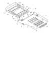
図1は本発明の第1の実施の形態におけるトレイ式カードソケットのカード装着前の状態を示す上方から見た斜視図、図2は本発明の第1の実施の形態におけるトレイ式カードソケットのカード装着前の状態を示す下方から見た斜視図である。  FIG. 1 is a perspective view of the tray type card socket according to the first embodiment of the present invention as seen from above showing a state before the card is mounted. FIG. 2 is a perspective view of the tray type card socket according to the first embodiment of the present invention. It is the perspective view seen from the lower part which shows the state before card | curd installation.

図1及び2において、10は本実施の形態におけるトレイ式カードソケットであり、図示されない電子機器に取付けられる。そして、前記トレイ式カードソケット10の内部にはカード51が装着され、前記トレイ式カードソケット10を介して、前記電子機器にカード51が装着される。なお、前記電子機器は、例えば、携帯電話機、PDA等であるが、いかなる種類の機器であってもよい。  1 and 2,reference numeral 10 denotes a tray-type card socket in the present embodiment, which is attached to an electronic device (not shown). Then, acard 51 is mounted inside the tray-type card socket 10, and thecard 51 is mounted on the electronic device via the tray-type card socket 10. The electronic device is, for example, a mobile phone or a PDA, but may be any type of device.

また、カード51は、例えば、SIMカード等のICカードであり、いかなる種類のカードであってもよいが、本実施の形態においては、SIMカードであるものとして説明する。また、本実施の形態において、トレイ式カードソケット10の各部の構成及び動作を説明するために使用される上、下、左、右、前、後等の方向を示す表現は、絶対的なものでなく相対的なものであり、トレイ式カードソケット10又はその部品が図に示される姿勢である場合に適切であるが、トレイ式カードソケット10又はその部品の姿勢が変化した場合には姿勢の変化に応じて変更して解釈されるべきものである。  Thecard 51 is, for example, an IC card such as a SIM card, and may be any type of card. In the present embodiment, thecard 51 is described as being a SIM card. Further, in the present embodiment, the expressions indicating directions such as upper, lower, left, right, front, rear, etc. used for explaining the configuration and operation of each part of the tray-type card socket 10 are absolute. It is appropriate if the traytype card socket 10 or its parts are in the posture shown in the figure, but if the posture of the traytype card socket 10 or its parts is changed, the posture is changed. It should be interpreted according to changes.

ここで、前記トレイ式カードソケット10は、合成樹脂等の絶縁材によって一体的に形成されたトレイホルダ11と、合成樹脂等の絶縁材によって一体的に形成され、前記トレイホルダ11に対してスライドさせて結合するトレイ41とを有する。前記カード51はトレイ41内に収容され、カード51を収容するトレイ41がトレイホルダ11内に収容されて結合されることによって、カード51がトレイ式カードソケット10の内部に装着される。  Here, the tray-type card socket 10 is integrally formed with an insulating material such as a synthetic resin, and atray holder 11 integrally formed with an insulating material such as a synthetic resin, and slides with respect to thetray holder 11. And atray 41 to be coupled. Thecard 51 is accommodated in thetray 41, and thetray 41 for accommodating thecard 51 is accommodated in thetray holder 11 and coupled, whereby thecard 51 is mounted inside the tray-type card socket 10.

そして、前記トレイ41は、矩形状の天板部44、及び、該天板部44の四方の周縁に沿って延在し、天板部44から下向きに立設する保持壁部42を有する。そして、該保持壁部42によって囲まれた天板部44下側の略矩形状の下向き凹部が、カード51を収容して保持するカード保持凹部43として機能する。また、前記保持壁部42は、天板部44の手前縁(図2における左上側縁)に沿って延在する手前壁部42a、天板部44の両側の側縁に沿って延在する第1側壁部42b及び第2側壁部42c、並びに、天板部44の奥縁(図2における右下側縁)に沿って延在する奥壁部42dから成る。そして、前記保持壁部42の内側面によって規定されるカード保持凹部43の大きさは、カード51の大きさよりわずかに大きい程度であり、また、カード保持凹部43の平面形状は、カード51の平面形状と同様である。図示される例において、カード51は略矩形の平面形状を有するが、一つの角部に切欠きが形成されている。そのため、カード保持凹部43の平面形状も一つの角部に切欠きが形成された略矩形となっている。  Thetray 41 has a rectangulartop plate portion 44 and a holding wall portion 42 that extends along the four peripheral edges of thetop plate portion 44 and stands downward from thetop plate portion 44. Then, a substantially rectangular downward concave portion below thetop plate portion 44 surrounded by the holding wall portion 42 functions as a card holdingconcave portion 43 that accommodates and holds thecard 51. Further, the holding wall portion 42 extends along thefront wall portion 42 a extending along the front edge (the upper left edge in FIG. 2) of thetop plate portion 44 and side edges on both sides of thetop plate portion 44. The firstside wall portion 42b and the secondside wall portion 42c, and theback wall portion 42d extending along the back edge of the top plate portion 44 (the lower right side edge in FIG. 2). The size of thecard holding recess 43 defined by the inner surface of the holding wall portion 42 is slightly larger than the size of thecard 51, and the planar shape of thecard holding recess 43 is the plane of thecard 51. The shape is the same. In the illustrated example, thecard 51 has a substantially rectangular planar shape, but a notch is formed at one corner. Therefore, the planar shape of thecard holding recess 43 is also substantially rectangular with a notch formed at one corner.

また、第1側壁部42bには、カンチレバー状のカード保持用板ばね部材45が取付けられ、該カード保持用板ばね部材45の自由端は、第1側壁部42bの内側壁面からカード保持凹部43内に突出している。そして、前記カード保持用板ばね部材45の自由端がカード保持凹部43内に収容されたカード51の側面を押圧することによって、該カード51がカード保持凹部43内に保持される。なお、カード51は、カード側接続端子としてのコンタクトパッド52が下を向くようにして、前記カード保持凹部43内に収容されて保持される。ここで、コンタクトパッド52は、カード51の一方の面(図2における下面)に複数、例えば、八個配設され、かつ、トレイ41がトレイホルダ11内に対してスライドする方向(図2における左上と右下とを結ぶ方向)に関して二列になるように配設されている。  Further, a cantilever-shaped card holdingleaf spring member 45 is attached to the firstside wall portion 42b, and the free end of the card holdingleaf spring member 45 extends from the inner wall surface of the firstside wall portion 42b to thecard holding recess 43. Protrusively inside. Then, the free end of the card holdingplate spring member 45 presses the side surface of thecard 51 accommodated in thecard holding recess 43, whereby thecard 51 is held in thecard holding recess 43. Thecard 51 is accommodated and held in thecard holding recess 43 so that thecontact pad 52 as a card side connection terminal faces downward. Here, a plurality of, for example, eightcontact pads 52 are provided on one surface (the lower surface in FIG. 2) of thecard 51, and the direction in which thetray 41 slides in the tray holder 11 (in FIG. 2). (The direction connecting the upper left and the lower right) is arranged in two rows.

さらに、第1側壁部42bの外側壁面には外方へ突出する第1ガイド突起46−1及び第2ガイド突起47−1が形成されている。ここで、第1ガイド突起46−1は前側、すなわち、トレイ41をトレイホルダ11内に挿入する方向に関して前寄りの位置に配設され、第2ガイド突起47−1は後側、すなわち、トレイ41をトレイホルダ11内に挿入する方向に関して後寄りの位置に配設されている。また、第2側壁部42cの外側壁面には外方へ突出する第1ガイド突起46−2及び第2ガイド突起47−2が形成されている。そして、第1ガイド突起46−2は前側、すなわち、トレイ41をトレイホルダ11内に挿入する方向に関して前寄りの位置に配設され、第2ガイド突起47−2は後側、すなわち、トレイ41をトレイホルダ11内に挿入する方向に関して後寄りの位置に配設されている。なお、第1側壁部42b及び第2側壁部42cの第1ガイド突起46−1及び第1ガイド突起46−2並びに第2ガイド突起47−1及び第2ガイド突起47−2を統合して説明する場合には、第1ガイド突起46及び第2ガイド突起47として説明する。なお、第1ガイド突起46は第2ガイド突起47より低い位置に配設される。また、第2ガイド突起47の手前側端部には、トレイホルダ11の後述されるガイド溝17の開放端部に当接することによって、トレイ41のトレイホルダ11に対する位置を決める位置決め突起47aが形成されている。該位置決め突起47aの傾斜面、すなわち、第2ガイド突起47の傾斜面は、ガイド溝17の開放端部の傾斜面に当接し、ガイド溝17に挿入されることによって、トレイ41を下方に移動させてトレイホルダ11に接近させる機能を備える。  Furthermore, the 1st guide protrusion 46-1 and the 2nd guide protrusion 47-1 which protrude outward are formed in the outer side wall surface of the 1stside wall part 42b. Here, the first guide protrusion 46-1 is disposed at the front side, that is, at the front position with respect to the direction in which thetray 41 is inserted into thetray holder 11, and the second guide protrusion 47-1 is at the rear side, that is, the tray. 41 is disposed at a rearward position with respect to the direction of inserting thetray 41 into thetray holder 11. A first guide protrusion 46-2 and a second guide protrusion 47-2 projecting outward are formed on the outer wall surface of the secondside wall portion 42c. The first guide protrusion 46-2 is disposed at the front side, that is, at the front position with respect to the direction in which thetray 41 is inserted into thetray holder 11, and the second guide protrusion 47-2 is at the rear side, that is, thetray 41. In thetray holder 11 in the rearward position. The first guide protrusion 46-1 and the first guide protrusion 46-2, the second guide protrusion 47-1 and the second guide protrusion 47-2 of the firstside wall part 42b and the secondside wall part 42c are integrated and described. In this case, thefirst guide protrusion 46 and thesecond guide protrusion 47 will be described. Thefirst guide protrusion 46 is disposed at a position lower than thesecond guide protrusion 47. In addition, apositioning protrusion 47 a that determines the position of thetray 41 with respect to thetray holder 11 is formed at the front end of thesecond guide protrusion 47 by contacting an open end of aguide groove 17 described later of thetray holder 11. Has been. The inclined surface of thepositioning protrusion 47a, that is, the inclined surface of thesecond guide protrusion 47 abuts on the inclined surface of the open end of theguide groove 17 and is inserted into theguide groove 17 to move thetray 41 downward. And a function of making thetray holder 11 approach.

そして、トレイホルダ11は、矩形状の底板部14、及び、該底板部14の三方の周縁に沿って延在し、底板部14から立設する壁部12を有する。そして、該壁部12によって囲まれた底板部14上の矩形の凹部が、トレイ41を収容するトレイ収容部13として機能する。また、前記壁部12は、底板部14の奥縁(図1における右上側縁)に沿って延在する奥壁部12a、並びに、底板部14の両側の側縁に沿って延在する第1側壁部12b及び第2側壁部12cから成る。そして、底板部14の手前縁(図1における左下側縁)は、壁部12が存在せずに開放されており、前記トレイ収容部13にトレイ41を挿入するために挿入口13aとして機能する。  Thetray holder 11 includes a rectangularbottom plate portion 14 and a wall portion 12 that extends along three peripheral edges of thebottom plate portion 14 and stands from thebottom plate portion 14. A rectangular concave portion on thebottom plate portion 14 surrounded by the wall portion 12 functions as a tray accommodating portion 13 that accommodates thetray 41. Further, the wall portion 12 extends along theback wall portion 12a extending along the back edge (upper right side edge in FIG. 1) of thebottom plate portion 14 and the side walls on both sides of thebottom plate portion 14. It consists of afirst side wall 12b and asecond side wall 12c. The front edge (the lower left edge in FIG. 1) of thebottom plate portion 14 is opened without the wall portion 12 and functions as aninsertion port 13a for inserting thetray 41 into the tray accommodating portion 13. .

また、底板部14には、接続端子収容孔(こう)15が複数形成され、該接続端子収容孔15の各々の中に、カード側接続端子としてのコンタクトパッド52に当接するホルダ側接続端子としての接続端子16が1つずつ配設されている。ここで、前記接続端子収容孔15及び接続端子16は、コンタクトパッド52と同数だけ配設され、かつ、該コンタクトパッド52と同様に、トレイ41をトレイホルダ11内に挿入する方向に関して二列になるように配設されている。これにより、カード51を保持したトレイ41がトレイホルダ11のトレイ収容部13内に完全に挿入された状態で、コンタクトパッド52の各々に接続端子16の各々が当接し、対応するコンタクトパッド52と接続端子16とが電気的に導通する。なお、前記接続端子収容孔15の底面を塞(ふさ)ぐことによって、接続端子収容凹部とすることもできる。  In addition, a plurality of connectionterminal receiving holes 15 are formed in thebottom plate portion 14, and each of the connectionterminal receiving holes 15 serves as a holder side connection terminal that contacts acontact pad 52 as a card side connection terminal. Are connected one by one. Here, the connectionterminal receiving holes 15 and theconnection terminals 16 are arranged in the same number as thecontact pads 52 and, like thecontact pads 52, in two rows in the direction in which thetray 41 is inserted into thetray holder 11. It is arranged to become. Thus, in a state where thetray 41 holding thecard 51 is completely inserted into the tray accommodating portion 13 of thetray holder 11, each of theconnection terminals 16 comes into contact with each of thecontact pads 52, and thecorresponding contact pads 52 and Theconnection terminal 16 is electrically connected. In addition, it can also be set as a connection terminal accommodation recessed part by plugging up the bottom face of the said connectionterminal accommodation hole 15. FIG.

そして、前記接続端子16は、金属板等のばね性を備える導電性の板材から成り、カンチレバー状に形成され、根本部が底板部14内に埋設されて固定され、先端近傍の接続部が底板部14の上面より上方に突出し、前記コンタクトパッド52に弾性的に当接するようになっている。また、前記トレイホルダ11の後方には、接続端子16の各々と導通するはんだ端子23が突出している。該はんだ端子23は、前記金属板等の導電性の板材から成り、電子機器における配線基板等に形成された信号線、コンタクトパッド、端子等、すなわち、相手側端子部材にはんだ付けされて電気的に接続される。  Theconnection terminal 16 is made of a conductive plate material having a spring property such as a metal plate, is formed in a cantilever shape, the root portion is embedded and fixed in thebottom plate portion 14, and the connection portion in the vicinity of the tip is the bottom plate. It protrudes upward from the upper surface of theportion 14 and elastically contacts thecontact pad 52. In addition,solder terminals 23 that are electrically connected to theconnection terminals 16 protrude behind thetray holder 11. Thesolder terminal 23 is made of a conductive plate material such as the metal plate, and is electrically connected to a signal line, a contact pad, a terminal, or the like formed on a wiring board or the like in an electronic device, that is, a mating terminal member. Connected to.

また、第1側壁部12b及び第2側壁部12cの内側壁面には、トレイ41をトレイホルダ11内にガイドするガイド通路として、トレイホルダ11の前後方向、すなわち、トレイ41をトレイホルダ11内に挿入する方向に延在するガイド溝17−1及びガイド溝17−2が各々形成されている。なお、第1側壁部12b及び第2側壁部12cのガイド溝17−1及びガイド溝17−2を統合して説明する場合には、ガイド溝17として説明する。該ガイド溝17は、奥側の端部が閉じて手前側(挿入口13a側)、すなわち、入口側の端部が開放されており、トレイ41の第1ガイド突起46及び第2ガイド突起47は、開放端部からガイド溝17内に挿入される。  Further, on the inner wall surfaces of the firstside wall portion 12 b and the secondside wall portion 12 c, as a guide passage for guiding thetray 41 into thetray holder 11, the front and rear direction of thetray holder 11, that is, thetray 41 into thetray holder 11. A guide groove 17-1 and a guide groove 17-2 extending in the insertion direction are formed. In addition, when the guide groove 17-1 and the guide groove 17-2 of the 1stside wall part 12b and the 2ndside wall part 12c are integrated and demonstrated, it demonstrates as theguide groove 17. FIG. Theguide groove 17 has an end on the back side closed and the front side (insertion port 13a side), that is, an end on the entrance side, is open, and thefirst guide protrusion 46 and thesecond guide protrusion 47 of thetray 41 are open. Is inserted into theguide groove 17 from the open end.

ここで、該ガイド溝17は、奥側に形成された第1段差部17a及び入口側に形成された第2段差部17bを有する。そして、前記ガイド溝17の少なくとも上面の位置は、開放端部から奥側の端部に向けて進行するに従い、次のように変化するように形成されている。すなわち、開放端部において最も高く、そのままの高さで底板部14上面と平行に進行し、第2段差部17bにおいて一段低下し、そのままの高さで底板部14上面と平行に進行し、第1段差部17aにおいて更に一段低下し、そのままの高さで底板部14上面と平行に進行し奥側の端部に到達する。なお、第1段差部17a及び第2段差部17bの前後におけるガイド溝17の少なくとも上面の差は、トレイ41の第1ガイド突起46と第2ガイド突起47の高さの差と同一である。また、第2段差部17bから第1段差部17aまでの距離は、トレイ41の第2ガイド突起47における前側の端部から第1ガイド突起46における前側の端部までの距離と同一である。これにより、第1ガイド突起46が第1段差部17aを通過する時に第2ガイド突起47が第2段差部17bを同時に通過し、トレイ41は、底板部14と平行な状態を保ちながら下方に移動させられ、トレイホルダ11に接近させられる。  Here, theguide groove 17 has a first steppedportion 17a formed on the back side and a second steppedportion 17b formed on the entrance side. The position of at least the upper surface of theguide groove 17 is formed to change as follows as it advances from the open end to the end on the back side. That is, it is the highest at the open end, proceeds parallel to the upper surface of thebottom plate portion 14 at the same height, decreases by one step at the second steppedportion 17b, travels parallel to the upper surface of thebottom plate portion 14 at the same height, The one steppedportion 17a is further lowered by one step, proceeds in parallel with the upper surface of thebottom plate portion 14 at the same height, and reaches the end on the back side. The difference in at least the upper surface of theguide groove 17 before and after thefirst step portion 17a and thesecond step portion 17b is the same as the difference in height between thefirst guide protrusion 46 and thesecond guide protrusion 47 of thetray 41. Further, the distance from thesecond step portion 17 b to thefirst step portion 17 a is the same as the distance from the front end portion of thesecond guide protrusion 47 of thetray 41 to the front end portion of thefirst guide protrusion 46. As a result, when thefirst guide protrusion 46 passes through the first steppedportion 17a, thesecond guide protrusion 47 passes through the second steppedportion 17b at the same time, and thetray 41 moves downward while maintaining a state parallel to thebottom plate portion 14. It is moved and brought close to thetray holder 11.

そして、第1側壁部12bの手前側の端面には、トレイ収容部13内に収容されたトレイ41がトレイ収容部13から離脱することを防止するロック部材としてのロックレバー18が取付けられている。該ロックレバー18は、回動軸18aを中心に回動するように取付けられている。また、底板部14には、第1側壁部12b及び第2側壁部12cに沿って延在するように第1収容凹部22−1及び第2収容凹部22−2が形成されている。該第1収容凹部22−1及び第2収容凹部22−2には、トレイ41の第1側壁部42b及び第2側壁部42cの下面部が収容される。さらに、トレイホルダ11の第1側壁部12b及び第2側壁部12cの外側壁面には、金属板等の板材から成るネイル21が取付けられている。該ネイル21は、トレイホルダ11を電子機器における配線基板等に固定するために、該配線基板等に形成された接続部に固定される。  Alock lever 18 as a lock member that prevents thetray 41 accommodated in the tray accommodating portion 13 from being detached from the tray accommodating portion 13 is attached to the front end face of the firstside wall portion 12b. . Thelock lever 18 is attached so as to rotate about arotation shaft 18a. Further, thebottom plate portion 14 is formed with a first receiving recess 22-1 and a second receiving recess 22-2 so as to extend along thefirst side wall 12b and thesecond side wall 12c. The first receiving recess 22-1 and the second receiving recess 22-2 receive the lower surface portions of the firstside wall portion 42b and the secondside wall portion 42c of thetray 41. Further, anail 21 made of a plate material such as a metal plate is attached to the outer wall surfaces of the firstside wall portion 12b and the secondside wall portion 12c of thetray holder 11. Thenail 21 is fixed to a connection portion formed on the wiring board or the like in order to fix thetray holder 11 to the wiring board or the like in the electronic device.

次に、前記構成のトレイ式カードソケット10のトレイホルダ11にトレイ41を介してカード51を装着する動作について説明する。  Next, an operation for mounting thecard 51 to thetray holder 11 of the tray-type card socket 10 having the above-described configuration via thetray 41 will be described.

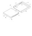
図3は本発明の第1の実施の形態におけるカードを保持するトレイをトレイホルダに挿入する前の状態を示す下方から見た斜視図、図4は本発明の第1の実施の形態におけるカードを保持するトレイをトレイホルダに挿入する途中の状態を示す上方から見た斜視図、図5は本発明の第1の実施の形態におけるカードを保持するトレイのトレイホルダへの挿入が完了した状態を示す上方から見た斜視図、図6は本発明の第1の実施の形態におけるカードを保持するトレイのトレイホルダへの挿入が完了した状態を示す断面図である。  FIG. 3 is a perspective view seen from below showing a state before the tray for holding the card in the first embodiment of the present invention is inserted into the tray holder, and FIG. 4 is a card in the first embodiment of the present invention. FIG. 5 is a perspective view seen from above showing a state in the middle of inserting the tray holding the card into the tray holder, and FIG. 5 shows a state where the insertion of the tray holding the card into the tray holder in the first embodiment of the present invention is completed FIG. 6 is a cross-sectional view showing a state in which insertion of the tray holding the card into the tray holder in the first embodiment of the present invention is completed.

まず、トレイ41のカード保持凹部43内にカード51をセットする。この場合、図3に示されるように、コンタクトパッド52が下を向くようにカード51をセットする。前記カード保持凹部43内に収容されたカード51は、カード保持用板ばね部材45によって保持される。また、ロックレバー18は、底板部14に対して起立した状態となっており、トレイホルダ11の挿入口13aが開放されている。  First, thecard 51 is set in thecard holding recess 43 of thetray 41. In this case, as shown in FIG. 3, thecard 51 is set so that thecontact pad 52 faces downward. Thecard 51 accommodated in thecard holding recess 43 is held by a card holdingleaf spring member 45. Further, thelock lever 18 is raised with respect to thebottom plate portion 14, and theinsertion port 13a of thetray holder 11 is opened.

そして、カード51を保持するトレイ41を、図3に示されるように、トレイホルダ11の挿入口13aの手前に位置させ、この状態からトレイ41をトレイホルダ11に向けて移動させ、トレイ収容部13内に挿入する。この場合、トレイホルダ11のガイド溝17にトレイ41の第1ガイド突起46及び第2ガイド突起47を順次挿入するようにして、トレイ41をトレイ収容部13内に挿入する。なお、第2ガイド突起47は、第1ガイド突起46が第2段差部17bを通過した後にガイド溝17内に進入する。そのため、トレイ41をトレイ収容部13内に挿入する初期の段階では、図4に示されるように、第2ガイド突起47はガイド溝17内に進入しておらず、第1ガイド突起46のみがガイド溝17によってガイドされた状態で、トレイ41がトレイ収容部13内に挿入される。  Then, as shown in FIG. 3, thetray 41 holding thecard 51 is positioned in front of theinsertion port 13a of thetray holder 11, and from this state, thetray 41 is moved toward thetray holder 11, and the tray accommodating portion 13 is inserted. In this case, thefirst guide protrusion 46 and thesecond guide protrusion 47 of thetray 41 are sequentially inserted into theguide groove 17 of thetray holder 11, and thetray 41 is inserted into the tray accommodating portion 13. Thesecond guide protrusion 47 enters theguide groove 17 after thefirst guide protrusion 46 passes through the second steppedportion 17b. Therefore, at the initial stage of inserting thetray 41 into the tray accommodating portion 13, as shown in FIG. 4, thesecond guide protrusion 47 does not enter theguide groove 17, and only thefirst guide protrusion 46 is present. Thetray 41 is inserted into the tray accommodating portion 13 while being guided by theguide groove 17.

この場合、第1ガイド突起46は、ガイド溝17における第2段差部17bから第1段差部17aまでの範囲を通過する。そして、該範囲におけるガイド溝17の位置は、第1段差部17aより奥側の範囲における位置よりも高くなっている。そのため、トレイ41に保持されたカード51の下面と底板部14の上面とがある程度離れた状態を保ちながら、トレイ41を進行させることができる。これにより、該トレイ41がトレイ収容部13内に挿入する際に、底板部14の上面より上方に突出している接続端子16の接続部は、コンタクトパッド52を含むカード51の下面に接触することがない。また、接触したとしても、カード51の下面と底板部14の上面とがある程度離れているので、接続端子16のばね力が弱くなっており、押付けられることがない。したがって、接続端子16の接続部がコンタクトパッド52を含むカード51の下面に押付けられた状態で摺接することを防止することができる。  In this case, thefirst guide protrusion 46 passes through the range of theguide groove 17 from the second steppedportion 17b to the first steppedportion 17a. The position of theguide groove 17 in the range is higher than the position in the range on the back side from the first steppedportion 17a. Therefore, thetray 41 can be advanced while maintaining the state where the lower surface of thecard 51 held on thetray 41 and the upper surface of thebottom plate portion 14 are separated to some extent. Thereby, when thetray 41 is inserted into the tray accommodating portion 13, the connection portion of theconnection terminal 16 protruding above the upper surface of thebottom plate portion 14 comes into contact with the lower surface of thecard 51 including thecontact pad 52. There is no. Even if they come into contact with each other, the lower surface of thecard 51 and the upper surface of thebottom plate portion 14 are separated from each other to some extent, so that the spring force of theconnection terminal 16 is weak and is not pressed. Therefore, it is possible to prevent the connection portion of theconnection terminal 16 from being in sliding contact with being pressed against the lower surface of thecard 51 including thecontact pad 52.

そして、前記トレイ41を更に進行させると、第2ガイド突起47がガイド溝17内に進入する。続いて、第1ガイド突起46が第1段差部17aを通過すると、第2ガイド突起47も第2段差部17bを同時に通過する。これにより、該トレイ41が底板部14と平行な状態を保ちながら下方に移動させられ、底板部14の上面に接近させられ、トレイ41の第1側壁部42b及び第2側壁部42cの下面部が、第1収容凹部22−1及び第2収容凹部22−2に収容される。そして、カード51の下面が底板部14の上面に接近するので、接続端子16のばね力が強くなり、各接続端子16の接続部が対応するコンタクトパッド52に押付けられる。これにより、各接続端子16の接続部と対応するコンタクトパッド52とが電気的に確実に接続される。  When thetray 41 is further advanced, thesecond guide projection 47 enters theguide groove 17. Subsequently, when thefirst guide protrusion 46 passes through the first steppedportion 17a, thesecond guide protrusion 47 also passes through the second steppedportion 17b at the same time. As a result, thetray 41 is moved downward while maintaining a state parallel to thebottom plate portion 14, is brought close to the upper surface of thebottom plate portion 14, and the lower surface portions of the firstside wall portion 42 b and the secondside wall portion 42 c of thetray 41. Are housed in the first housing recess 22-1 and the second housing recess 22-2. Then, since the lower surface of thecard 51 approaches the upper surface of thebottom plate portion 14, the spring force of theconnection terminal 16 becomes strong, and the connection portion of eachconnection terminal 16 is pressed against thecorresponding contact pad 52. Thereby, the connection part of eachconnection terminal 16 and thecorresponding contact pad 52 are electrically connected reliably.

続いて、第2ガイド突起47の位置決め突起47aがガイド溝17の開放端部に挿入されると、トレイ41の先端部がトレイホルダ11の奥壁部12aの内面に当接し、トレイ41の進行が停止させられ、カード51を保持するトレイ41が位置決めされ、該トレイ41の挿入が完了する。また、前記位置決め突起47aの傾斜面がガイド溝17の開放端部の傾斜面に当接し、ガイド溝17に挿入されることによって、下方に移動させる力が更にトレイ41に加えられる。続いて、ロックレバー18を回動させて横臥(が)した状態にし、図5に示されるように、第1側壁部42bの手前側端面に係止させてトレイ41をロックする。これにより、該トレイ41がトレイホルダ11内から抜出ることが防止され、カード51のトレイ式カードソケット10への装着が完了する。この状態においては、図6に示されるように、接続端子16は、コンタクトパッド52によって下方に押されて変形し、接続端16の大分部が接続端子収容孔15内に収容されている。そのため、接続端子16のばね力が強くなっており、接続端子16の接続部とコンタクトパッド52との接圧が強くなっている。  Subsequently, when thepositioning protrusion 47 a of thesecond guide protrusion 47 is inserted into the open end portion of theguide groove 17, the tip end portion of thetray 41 comes into contact with the inner surface of therear wall portion 12 a of thetray holder 11, and thetray 41 proceeds. Is stopped, thetray 41 holding thecard 51 is positioned, and the insertion of thetray 41 is completed. Further, the inclined surface of thepositioning projection 47 a abuts on the inclined surface of the open end portion of theguide groove 17 and is inserted into theguide groove 17, whereby a force for moving downward is further applied to thetray 41. Subsequently, thelock lever 18 is turned into a recumbent state, and thetray 41 is locked by being engaged with the front end surface of the firstside wall portion 42b as shown in FIG. As a result, thetray 41 is prevented from being pulled out from thetray holder 11, and the mounting of thecard 51 into the tray-type card socket 10 is completed. In this state, as shown in FIG. 6, theconnection terminal 16 is deformed by being pushed downward by thecontact pad 52, and a large part of theconnection end 16 is accommodated in the connectionterminal accommodation hole 15. For this reason, the spring force of theconnection terminal 16 is increased, and the contact pressure between the connection portion of theconnection terminal 16 and thecontact pad 52 is increased.

次に、トレイ41をトレイホルダ11に挿入する際の第1ガイド突起46及び第2ガイド突起47とガイド溝17との位置関係について詳細に説明する。  Next, the positional relationship between thefirst guide protrusion 46 and thesecond guide protrusion 47 and theguide groove 17 when thetray 41 is inserted into thetray holder 11 will be described in detail.

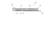
図7は本発明の第1の実施の形態における第1ガイド突起及び第2ガイド突起とガイド溝との位置関係を示す断面図である。なお、図7においては、第1ガイド突起及び第2ガイド突起並びにガイド溝以外の部材の図示が適宜省略されている。  FIG. 7 is a cross-sectional view showing the positional relationship between the first guide protrusion, the second guide protrusion, and the guide groove in the first embodiment of the present invention. In FIG. 7, illustration of members other than the first guide protrusion, the second guide protrusion, and the guide groove is omitted as appropriate.

まず、トレイ41をトレイホルダ11の挿入口13aの手前に位置させ、トレイ41をトレイ収容部13内に挿入する直前の状態が図7(a)に示されている。図7(a)から、第1ガイド突起46が第2ガイド突起47より低い位置に配設されていることが分かる。  First, FIG. 7A shows a state immediately before thetray 41 is positioned in front of theinsertion port 13a of thetray holder 11 and thetray 41 is inserted into the tray accommodating portion 13. FIG. From FIG. 7A, it can be seen that thefirst guide protrusion 46 is disposed at a position lower than thesecond guide protrusion 47.

続いて、トレイ41をトレイホルダ11に向けて移動させ、該トレイホルダ11のガイド溝17にトレイ41の第1ガイド突起46を挿入した状態が図7(b)に示されている。この状態において、第2ガイド突起47は未だガイド溝17に挿入されておらず、第1ガイド突起46の奥側端部は第1段差部17aを通過した直後である。そして、トレイ41の進行によって、第1ガイド突起46は、ガイド溝17における第2段差部17bから第1段差部17aまでの範囲を通過する。  Subsequently, the state in which thetray 41 is moved toward thetray holder 11 and thefirst guide protrusion 46 of thetray 41 is inserted into theguide groove 17 of thetray holder 11 is shown in FIG. In this state, thesecond guide protrusion 47 has not yet been inserted into theguide groove 17, and the rear end portion of thefirst guide protrusion 46 is immediately after passing through the first steppedportion 17 a. Then, as thetray 41 advances, thefirst guide protrusion 46 passes through the range from the second steppedportion 17b to the first steppedportion 17a in theguide groove 17.

続いて、前記トレイ41が更に進行し、第1ガイド突起46が第1段差部17aに接近すると、第2ガイド突起47がガイド溝17内に進入する。そして図7(c)に示されるように、第1ガイド突起46の奥側端部が第1段差部17aに到達すると、第2ガイド突起47の奥側端部も第2段差部17bに同時に到達する。この場合、第1ガイド突起46は第2ガイド突起47より低い位置に配設されているが、第2段差部17bの前後におけるガイド溝17の上面の差がトレイ41の第1ガイド突起46と第2ガイド突起47の高さの差と同一であるので、トレイ41及びカード51の下面と底板部14の上面とは平行に保持される。  Subsequently, when thetray 41 further advances and thefirst guide protrusion 46 approaches the first steppedportion 17 a, thesecond guide protrusion 47 enters theguide groove 17. Then, as shown in FIG. 7C, when the back end of thefirst guide protrusion 46 reaches the first steppedportion 17a, the back end of thesecond guide protrusion 47 is also simultaneously with the second steppedportion 17b. To reach. In this case, thefirst guide protrusion 46 is disposed at a position lower than thesecond guide protrusion 47, but the difference in the upper surface of theguide groove 17 before and after the second steppedportion 17 b is different from that of thefirst guide protrusion 46 of thetray 41. Since the difference in height between thesecond guide protrusions 47 is the same, the lower surfaces of thetray 41 and thecard 51 and the upper surface of thebottom plate portion 14 are held in parallel.

続いて、前記トレイ41が更に進行し、第1ガイド突起46の奥側端部が第1段差部17aを通過すると、第2ガイド突起47の奥側端部も第2段差部17bを同時に通過する。これにより、トレイ41及びカード51の下面が底板部14の上面と平行な状態を保ちながら下方に移動させられ、底板部14の上面に接近させられる。そして、図7(d)に示されるように、第2ガイド突起47の位置決め突起47aがガイド溝17の開放端部に当接し、ガイド溝17に挿入されると、トレイ41の先端部がトレイホルダ11の奥壁部12aの内面に当接し、トレイ41の進行が停止させられ、該トレイ41の挿入が完了し、カード51を保持するトレイ41が位置決めされる。  Subsequently, when thetray 41 further advances and the back end portion of thefirst guide protrusion 46 passes through thefirst step portion 17a, the back end portion of thesecond guide protrusion 47 also passes through thesecond step portion 17b at the same time. To do. Accordingly, the lower surface of thetray 41 and thecard 51 is moved downward while maintaining a state parallel to the upper surface of thebottom plate portion 14, and is brought close to the upper surface of thebottom plate portion 14. 7D, thepositioning protrusion 47a of thesecond guide protrusion 47 abuts on the open end of theguide groove 17, and when theguide groove 17 is inserted, the front end of thetray 41 is moved to the tray. Abutting on the inner surface of theback wall portion 12a of theholder 11, the progress of thetray 41 is stopped, the insertion of thetray 41 is completed, and thetray 41 holding thecard 51 is positioned.

なお、図7(d)から分かるように、第1ガイド突起46の奥側端部及び第2ガイド突起47の奥側端部が第1段差部17a及び第2段差部17bを通過して、トレイ41及びカード51の下面が下方に移動させられるのは、トレイ41の挿入が完了してカード51を保持するトレイ41が位置決めされる直前である。そのため、各接続端子16の接続部が対応するコンタクトパッド52に押付けられた状態で、トレイ41が進行する距離は短くなっている。  As can be seen from FIG. 7 (d), the back end of thefirst guide protrusion 46 and the back end of thesecond guide protrusion 47 pass through thefirst step 17a and thesecond step 17b, The bottom surfaces of thetray 41 and thecard 51 are moved downward just before thetray 41 holding thecard 51 is positioned after the insertion of thetray 41 is completed. For this reason, the distance traveled by thetray 41 is shortened in a state where the connection portion of eachconnection terminal 16 is pressed against thecorresponding contact pad 52.

このように、本実施の形態においては、トレイ41をトレイホルダ11内にガイドするガイド溝17に第1段差部17a及び第2段差部17bを設け、トレイ41をトレイホルダ11内に挿入する際に、挿入が完了する直前にトレイ41に収容されたカード51のコンタクトパッド52がトレイホルダ11の接続端子16に押付けられるようになっている。  As described above, in the present embodiment, thefirst step portion 17 a and thesecond step portion 17 b are provided in theguide groove 17 that guides thetray 41 into thetray holder 11, and thetray 41 is inserted into thetray holder 11. In addition, thecontact pad 52 of thecard 51 accommodated in thetray 41 is pressed against theconnection terminal 16 of thetray holder 11 immediately before the insertion is completed.

そのため、該接続端子16が、カード51の下面において対応するコンタクトパッド52以外の面、すなわち、対応しないコンタクトパッド52の面やコンタクトパッド52の存在しない面に押付けられた状態で摺接することを防止することができる。  Therefore, theconnection terminal 16 is prevented from sliding in a state where it is pressed against a surface other than thecorresponding contact pad 52 on the lower surface of thecard 51, that is, a surface of thenon-corresponding contact pad 52 or a surface where thecontact pad 52 does not exist. can do.

ここで、対応しないコンタクトパッド52とは、手前側の列に配設されている接続端子16に対しての、トレイ41をトレイホルダ11内に挿入する方向に関して前寄りの列に配設されているコンタクトパッド52のことである。すなわち、接続端子16及びコンタクトパッド52が、トレイ41をトレイホルダ11内に挿入する方向に関して複数列を形成するように配設されている場合、各列における幅方向の配列がほぼ同様であるとすると、トレイ41が挿入される際に、最も後寄りの列以外のコンタクトパッド52は、対応しない列の接続端子16の上方を通過する。また、同様に、最も奥側の列以外の接続端子16は、対応しない列のコンタクトパッド52の下方を相対的に通過する。そのため、カード51の下面が底板部14の上面に接近した状態でトレイ41をトレイホルダ11内に挿入すると、最も後寄りの列以外のコンタクトパッド52に、対応しない列の接続端子16が押付けられた状態で摺接することになる。それに対し、本実施の形態においては、挿入が完了する直前までは、カード51の下面が底板部14の上面から離間した状態でトレイ41をトレイホルダ11内に挿入されるので、コンタクトパッド52に対応しない列の接続端子16が接触しないか、又は、接触しても、接続端子16のばね力が弱くなっており、押付けられることがない。したがって、接続端子16が対応しない列のコンタクトパッド52に押付けられた状態で摺接することを防止することができる。また、コンタクトパッド52の存在しない面についても同様である。  Here, thenon-corresponding contact pads 52 are arranged in the front row with respect to the direction in which thetray 41 is inserted into thetray holder 11 with respect to theconnection terminals 16 arranged in the front row. It is thecontact pad 52 that is present. That is, when theconnection terminals 16 and thecontact pads 52 are arranged so as to form a plurality of rows in the direction in which thetray 41 is inserted into thetray holder 11, the arrangement in the width direction in each row is substantially the same. Then, when thetray 41 is inserted, thecontact pads 52 other than the rearmost row pass over theconnection terminals 16 in the non-corresponding row. Similarly, theconnection terminals 16 other than the innermost row pass relatively below thecontact pads 52 in the non-corresponding rows. For this reason, when thetray 41 is inserted into thetray holder 11 with the lower surface of thecard 51 approaching the upper surface of thebottom plate portion 14, theconnection terminals 16 in the corresponding row are pressed against thecontact pads 52 other than the rearmost row. Will be in sliding contact. On the other hand, in the present embodiment, until the insertion is completed, thetray 41 is inserted into thetray holder 11 with the lower surface of thecard 51 being separated from the upper surface of thebottom plate portion 14, so Even if theconnection terminals 16 in the non-corresponding rows do not contact or contact, the spring force of theconnection terminals 16 is weak and is not pressed. Accordingly, it is possible to prevent theconnection terminal 16 from being in sliding contact with being pressed against thecontact pad 52 in the corresponding row. The same applies to the surface where thecontact pad 52 does not exist.

さらに、トレイ41が下方に移動させられるのは、トレイ41の挿入が完了して位置決めされる直前であるので、接続端子16が対応するコンタクトパッド52に押付けられた状態で摺接する距離を短くすることができる。  Further, since thetray 41 is moved downward immediately before thetray 41 is completely inserted and positioned, the distance in which theconnection terminal 16 is slid in contact with thecorresponding contact pad 52 is shortened. be able to.

したがって、カード51の下面、コンタクトパッド52及び接続端子16が損傷を受けることを防止することができ、カード51の下面、コンタクトパッド52及び接続端子16の耐久性を高め、信頼性を向上させることができる。  Therefore, the lower surface of thecard 51, thecontact pad 52, and theconnection terminal 16 can be prevented from being damaged, and the durability of the lower surface of thecard 51, thecontact pad 52, and theconnection terminal 16 can be improved and the reliability can be improved. Can do.

また、前記第1段差部17a及び第2段差部17bの段差の大きさを調整することによって、トレイ41が下方に移動する量を調節し、それにより、カード51の下面が接続端子16を押下げる量を調整することによって、接続端子16のばね力を調節することができる。そのため、接続端子16と対応するコンタクトパッド52とが当接する接圧の大きさを容易に調整することができる。  Further, the amount of movement of thetray 41 is adjusted by adjusting the size of the steps of thefirst step portion 17a and thesecond step portion 17b, whereby the lower surface of thecard 51 pushes theconnection terminal 16. The spring force of theconnection terminal 16 can be adjusted by adjusting the amount to be lowered. Therefore, it is possible to easily adjust the magnitude of the contact pressure at which theconnection terminal 16 contacts thecorresponding contact pad 52.

なお、本実施の形態においては、接続端子16がばね性を有するものである場合について説明したが、前記コンタクトパッド52に代えてばね性を有する接続端子をカード51の下面に配設し、接続端子16に代えてパッド状の接続端子を底板部14の上面に配設することもできる。この場合、底板部14の上面がカード51の下面に配設された接続端子によって損傷を受けることが防止される。  In the present embodiment, the case where theconnection terminal 16 has a spring property has been described. However, instead of thecontact pad 52, a connection terminal having a spring property is disposed on the lower surface of thecard 51 to connect theconnection terminal 16. Instead of theterminals 16, pad-like connection terminals can be disposed on the upper surface of thebottom plate portion 14. In this case, the upper surface of thebottom plate portion 14 is prevented from being damaged by the connection terminals disposed on the lower surface of thecard 51.

次に、本発明の第2の実施の形態について説明する。なお、第1の実施の形態と同じ構造を有するものについては、同じ符号を付与することによってその説明を省略する。また、前記第1の実施の形態と同じ動作及び同じ効果についても、その説明を省略する。  Next, a second embodiment of the present invention will be described. In addition, about what has the same structure as 1st Embodiment, the description is abbreviate | omitted by providing the same code | symbol. The description of the same operation and the same effect as those of the first embodiment is also omitted.

図8は本発明の第2の実施の形態におけるトレイ式カードソケットのトレイへの挿入前の状態を示す上方から見た斜視図である。なお、図8においては、第1ガイド突起及び第2ガイド突起並びにガイド溝以外の部材の図示が適宜省略されている。  FIG. 8 is a perspective view seen from above showing a state before insertion of the tray-type card socket into the tray in the second embodiment of the present invention. In FIG. 8, illustration of members other than the first guide protrusion, the second guide protrusion, and the guide groove is omitted as appropriate.

本実施の形態において、トレイ41の第1側壁部42b及び第2側壁部42cの外側壁面には、第1ガイド突起46及び第2ガイド突起47の代わりにガイド溝17が形成され、また、トレイホルダ11の第1側壁部12b及び第2側壁部12cの内側壁面には、ガイド溝17の代わりに第1ガイド突起46及び第2ガイド突起47が形成されている。なお、図8において、底板部14に形成された接続端子収容孔15及び該接続端子収容孔15内に配設された接続端子16は、図示が省略されているが、前記第1の実施の形態と同様である。  In the present embodiment, guidegrooves 17 are formed on the outer wall surfaces of the firstside wall portion 42b and the secondside wall portion 42c of thetray 41 in place of thefirst guide protrusions 46 and thesecond guide protrusions 47, and the tray Instead of theguide groove 17, afirst guide protrusion 46 and asecond guide protrusion 47 are formed on the inner wall surfaces of the firstside wall part 12 b and the secondside wall part 12 c of theholder 11. In FIG. 8, the connectionterminal accommodation hole 15 formed in thebottom plate portion 14 and theconnection terminal 16 disposed in the connectionterminal accommodation hole 15 are not shown, but the first embodiment It is the same as the form.

この場合、ガイド溝17は、単一の段差部を備え、前記第1の実施の形態におけるガイド溝17と上下の関係が逆になっている。すなわち、ガイド溝17の奥側(図8における左下側)に形成された第1段差部17aを備えているが、前記第1の実施の形態における第2段差部17bは備えていない。そして、ガイド溝17の少なくとも下面の位置は、ガイド溝17の入口側(図8における右上側)に形成された開放端部から奥側の端部に向けて進行するに従い、次のように変化するように形成されている。すなわち、開放端部において最も低く、そのままの高さで底板部14上面と平行に進行し、第1段差部17aにおいて一段上昇し、そのままの高さで底板部14上面と平行に進行し奥側の端部に到達する。また、第1ガイド突起46は第2ガイド突起47より低い位置に配設される。  In this case, theguide groove 17 includes a single step portion, and the vertical relationship with theguide groove 17 in the first embodiment is reversed. That is, thefirst step portion 17a formed on the back side (the lower left side in FIG. 8) of theguide groove 17 is provided, but thesecond step portion 17b in the first embodiment is not provided. The position of at least the lower surface of theguide groove 17 changes as follows from the open end formed on the inlet side (upper right side in FIG. 8) of theguide groove 17 toward the back end. It is formed to do. That is, it is the lowest at the open end, proceeds in parallel with the upper surface of thebottom plate portion 14 at the same height, rises one step at the first steppedportion 17a, proceeds in parallel with the upper surface of thebottom plate portion 14 at the same height, and goes back. Reach the end of the. Further, thefirst guide protrusion 46 is disposed at a position lower than thesecond guide protrusion 47.

そして、第1ガイド突起46が第1段差部17aを通過すると、トレイ41が底板部14と平行な状態を保ちながら下方に移動させられ、底板部14の上面に接近させられる。また、第2ガイド突起47の位置決め突起47aがガイド溝17の開放端部に挿入されると、前記位置決め突起47aの傾斜面、すなわち、第2ガイド突起47の傾斜面がガイド溝17の開放端部に当接し、ガイド溝17に挿入されることによって、下方に移動させる力がトレイ41に加えられる。そのため、カード51の下面が底板部14の上面に接近するので、接続端子16のばね力が強くなり、各接続端子16の接続部が対応するコンタクトパッド52に押付けられる。これにより、各接続端子16の接続部と対応するコンタクトパッド52とが電気的に確実に接続される。  Then, when thefirst guide protrusion 46 passes through thefirst step portion 17 a, thetray 41 is moved downward while maintaining a state parallel to thebottom plate portion 14, and is brought close to the upper surface of thebottom plate portion 14. When thepositioning protrusion 47 a of thesecond guide protrusion 47 is inserted into the open end of theguide groove 17, the inclined surface of thepositioning protrusion 47 a, that is, the inclined surface of thesecond guide protrusion 47 is the open end of theguide groove 17. A force to move downward is applied to thetray 41 by being in contact with the portion and being inserted into theguide groove 17. Therefore, since the lower surface of thecard 51 approaches the upper surface of thebottom plate portion 14, the spring force of theconnection terminal 16 becomes strong, and the connection portion of eachconnection terminal 16 is pressed against thecorresponding contact pad 52. Thereby, the connection part of eachconnection terminal 16 and thecorresponding contact pad 52 are electrically connected reliably.

その他の点の構成については、前記第1の実施の形態と同様であるので、説明を省略する。また、トレイ41をトレイホルダ11内に挿入する際の動作についても、前記第1の実施の形態と同様であるので、説明を省略する。  Since other configurations are the same as those in the first embodiment, description thereof is omitted. Also, the operation when inserting thetray 41 into thetray holder 11 is the same as that in the first embodiment, and the description thereof is omitted.

次に、本発明の第3の実施の形態について説明する。なお、第1及び第2の実施の形態と同じ構造を有するものについては、同じ符号を付与することによってその説明を省略する。また、前記第1及び第2の実施の形態と同じ動作及び同じ効果についても、その説明を省略する。  Next, a third embodiment of the present invention will be described. In addition, about the thing which has the same structure as 1st and 2nd embodiment, the description is abbreviate | omitted by providing the same code | symbol. Also, the description of the same operations and effects as those of the first and second embodiments is omitted.

図9は本発明の第3の実施の形態におけるトレイ式カードソケットのトレイへの挿入前の状態を示す上方から見た斜視図である。なお、図9においては、第1ガイド突起及び第2ガイド突起の部材の図示が適宜省略されている。  FIG. 9 is a perspective view seen from above showing a state before the tray-type card socket is inserted into the tray according to the third embodiment of the present invention. In FIG. 9, illustration of the members of the first guide protrusion and the second guide protrusion is omitted as appropriate.

本実施の形態においては、トレイ41がトレイホルダ11の周囲に覆い被さるようにして、トレイホルダ11に結合される。そして、トレイ41の第1側壁部42b及び第2側壁部42cの内側壁面にはガイド溝17が形成され、また、トレイホルダ11の第1側壁部12b及び第2側壁部12cの外側壁面には、第1ガイド突起46及び第2ガイド突起47が形成されている。なお、図9において、底板部14に形成された接続端子収容孔15及び該接続端子収容孔15内に配設された接続端子16は、図示が省略されているが、前記第1及び第2の実施の形態と同様である。  In the present embodiment, thetray 41 is coupled to thetray holder 11 so as to cover the periphery of thetray holder 11. Theguide groove 17 is formed on the inner wall surface of the firstside wall portion 42b and the secondside wall portion 42c of thetray 41, and the outer wall surface of the firstside wall portion 12b and the secondside wall portion 12c of thetray holder 11 is formed. Afirst guide protrusion 46 and asecond guide protrusion 47 are formed. In FIG. 9, the connectionterminal accommodation hole 15 formed in thebottom plate portion 14 and theconnection terminal 16 disposed in the connectionterminal accommodation hole 15 are not shown, but the first and second This is the same as the embodiment.

この場合、ガイド溝17は、前記第2の実施の形態と同様に、前記第1の実施の形態におけるガイド溝17と上下の関係が逆になっている。また、また、第1ガイド突起46も、前記第2の実施の形態と同様に、第2ガイド突起47より高い位置に配設される。  In this case, theguide groove 17 has an upside-down relationship with theguide groove 17 in the first embodiment, as in the second embodiment. Further, thefirst guide protrusion 46 is also disposed at a position higher than thesecond guide protrusion 47 as in the second embodiment.

その他の点の構成については、前記第1及び第2の実施の形態と同様であるので、説明を省略する。また、トレイ41をトレイホルダ11に結合する際の動作についても、前記第1及び第2の実施の形態と同様であるので、説明を省略する。  Since the configuration of other points is the same as that of the first and second embodiments, description thereof is omitted. Further, the operation when thetray 41 is coupled to thetray holder 11 is also the same as that in the first and second embodiments, and thus the description thereof is omitted.

なお、本発明は前記実施の形態に限定されるものではなく、本発明の趣旨に基づいて種々変形させることが可能であり、それらを本発明の範囲から排除するものではない。  In addition, this invention is not limited to the said embodiment, It can change variously based on the meaning of this invention, and does not exclude them from the scope of the present invention.

本発明の第1の実施の形態におけるトレイ式カードソケットのカード装着前の状態を示す上方から見た斜視図である。It is the perspective view seen from the upper direction which shows the state before card | curd mounting | wearing of the tray type | mold card socket in the 1st Embodiment of this invention.本発明の第1の実施の形態におけるトレイ式カードソケットのカード装着前の状態を示す下方から見た斜視図である。It is the perspective view seen from the lower part which shows the state before the card | curd installation of the tray type | mold card socket in the 1st Embodiment of this invention.本発明の第1の実施の形態におけるカードを保持するトレイをトレイホルダに挿入する前の状態を示す下方から見た斜視図である。It is the perspective view seen from the lower part which shows the state before inserting the tray holding the card | curd in the 1st Embodiment of this invention in a tray holder.本発明の第1の実施の形態におけるカードを保持するトレイをトレイホルダに挿入する途中の状態を示す上方から見た斜視図である。It is the perspective view seen from the upper part which shows the state in the middle of inserting the tray holding the card | curd in the 1st Embodiment of this invention in a tray holder.本発明の第1の実施の形態におけるカードを保持するトレイのトレイホルダへの挿入が完了した状態を示す上方から見た斜視図である。It is the perspective view seen from the upper part which shows the state which the insertion to the tray holder of the tray holding the card | curd in the 1st Embodiment of this invention was completed.本発明の第1の実施の形態におけるカードを保持するトレイのトレイホルダへの挿入が完了した状態を示す断面図である。It is sectional drawing which shows the state which the insertion to the tray holder of the tray holding the card | curd in the 1st Embodiment of this invention was completed.本発明の第1の実施の形態における第1ガイド突起及び第2ガイド突起とガイド溝との位置関係を示す断面図である。It is sectional drawing which shows the positional relationship of the 1st guide protrusion in the 1st Embodiment of this invention, the 2nd guide protrusion, and a guide groove.本発明の第2の実施の形態におけるトレイ式カードソケットのトレイへの挿入前の状態を示す上方から見た斜視図である。It is the perspective view seen from the upper side which shows the state before insertion to the tray of the tray-type card socket in the 2nd Embodiment of this invention.本発明の第3の実施の形態におけるトレイ式カードソケットのトレイへの挿入前の状態を示す上方から見た斜視図である。It is the perspective view seen from the upper side which shows the state before insertion in the tray of the tray type | mold card socket in the 3rd Embodiment of this invention.従来のトレイ式カードソケットを示す図である。It is a figure which shows the conventional tray type | mold card socket.

符号の説明Explanation of symbols

10 トレイ式カードソケット
11、301 トレイホルダ
12 壁部
12a、42d 奥壁部
12b、42b 第1側壁部
12c、42c 第2側壁部
13 トレイ収容部
13a 挿入口
14 底板部
15 接続端子収容孔
16、304 接続端子
17、17−1、17−2、306、307 ガイド溝
17a 第1段差部
17b 第2段差部
18 ロックレバー
18a 回動軸
21 ネイル
22−1 第1収容凹部
22−2 第2収容凹部
23、305 はんだ端子
41、302 トレイ
42 保持壁部
42a 手前壁部
43 カード保持凹部
44 天板部
45 カード保持用板ばね部材
46、46−1、46−2 第1ガイド突起
47、47−1、47−2 第2ガイド突起
47a 位置決め突起
51 カード
52 コンタクトパッド
303 保持用板ばね部材
308、309 ガイド突起
DESCRIPTION OFSYMBOLS 10 Tray-type card socket 11, 301 Tray holder 12Wall part 12a, 42dBack wall part 12b, 42b 1stside wall part 12c, 42c 2nd side wall part 13Tray accommodating part13a Insertion slot 14Bottom plate part 15 Connectionterminal accommodating hole 16, 304Connection terminals 17, 17-1, 17-2, 306, 307Guide groove 17aFirst step portion 17bSecond step portion 18Lock lever18a Rotating shaft 21 Nail 22-1 First housing recess 22-2Second housing Recess 23, 305Solder terminal 41, 302 Tray 42Holding wall42a Front wall 43Card holding recess 44Top plate 45 Card holdingleaf spring members 46, 46-1, 46-2 First guideprotrusions 47, 47- 1, 47-2Second guide protrusion47a Positioning protrusion 51Card 52Contact pad 303 Holdingleaf spring member 308, 309 Guy Protuberance

Claims (5)

Translated fromJapanese
(a)一面にカード側接続端子を備えるカードを、前記カード側接続端子が露出するように収容するトレイと
(b)前記一面と対向する面に前記カード側接続端子に当接するホルダ側接続端子を備え、前記トレイをスライドさせて結合するトレイホルダとを有するトレイ式カードソケットであって、
(c)前記トレイ又はトレイホルダのうちの一方の部材はガイド突起を備え、他方の部材は前記ガイド突起をガイドするガイド通路を備え、
(d)該ガイド通路は、前記ガイド突起が通過することによって、前記一方の部材が他方の部材に接近する段差部を備え、
(e)前記ガイド突起は、前側に形成された第1ガイド突起及び後側に形成された第2ガイド突起を含み、
(f)前記段差部は、奥側に形成された第1段差部及び入口側に形成された第2段差部を含み、
)前記トレイとトレイホルダとの結合が完了する直前に、前記第1ガイド突起及び第2ガイド突起は、同時に前記第1段差部及び第2段差部を各々通過し、前記カード側接続端子がホルダ側接続端子に押付けられることを特徴とするトレイ式カードソケット。
(A)a trayfor a card witha card-side connectionpin on one side, to house so that the card-side connectionpin is exposed,
(B) the providedabutting the holder side connectionpinto said card side connectionpin on one surface which faces,a tray type cardsocketand a Toreihoruda binding by slidingthe tray,
(C) the one partmaterial ofthetray or ToreihoruDacomprisesa guide collisionforce,the other partsmember includesa guide passagepath for guidingthe guide collisionforce,
(D) the guide passagepath by passing through the guide collisionouts, provided witha steppedportion to which the one partmaterial approachesthe other partsmember,
(E) The guide protrusion includes a first guide protrusion formed on the front side and a second guide protrusion formed on the rear side,
(F) The step portion includes a first step portion formed on the back side and a second step portion formed on the entrance side,
(G) just before coupling is completedbetween thetray and ToreihoruDa, the first guide projection and the second guide protrusions, respectively throughthe first and second stepped portions at the same time, the card-side connection tray type cardsocket, characterized in that thepin is pressed againstthe holder-side connectingterminal.
前記カード側接続端子及びホルダ側接続端子は、前記トレイがスライドする方向に関して複数の列を形成するように配設される請求項1に記載のトレイ式カードソケット。The card-side connectingpin及 beauty holder side connectionpin, the tray type cardsocket according to claim 1, wherein thetray is disposed so as to form a plurality of rows with respect to the slidingdirection.(a)前記第2ガイド突起は傾斜面を備え
(b)前記ガイド通路は傾斜面を備える開放端部を含み、
(c)前記第1ガイド突起は前記第1段差部を通過し、前記第2ガイド突起の傾斜面は前記ガイド通路の開放端部の傾斜面に当接して前記ガイド通路に挿入される請求項1又は2に記載のトレイ式カードソケット。
(A)the second guide protrusion has aninclined surface ;
(B) the guide passagepath includes an open end portion having an inclined surface,
(C) said first guide collisionforcepasses through thefirst steppedportion, the inclined surfaceof the second guide collisionforce is insertedinto the guide passagepath in contact with theinclined surface of the open end portionof the guide throughpassage tray type cardsocket according to claim 1 or 2is.
前記一方の部材は、他方の部材の離脱を防止するロック部材を備える請求項1〜のいずれか1項に記載のトレイ式カードソケット。The one partmaterial, tray type cardsocket according to any one of claims 1 to3 includinga lockingmember for preventing the disengagementof the other partmaterial.前記ホルダ側接続端子又はカード側接続端子のうちのいずれか一方の接続端子は、ばね性を備え、他方の接続端子に弾性的に当接する請求項1〜のいずれか1項に記載のトレイ式カードソケット。One of the connectionpinof the holder-side connecting endKomata the card-side connection endterminalis provided with a spring property, any of the claims1-4 which resiliently abutsto the other connectionpin 1 tray type cardsocket according toclaim.
JP2005148132A2005-05-202005-05-20 Tray card socketExpired - Fee RelatedJP4628183B2 (en)

Priority Applications (1)

Application NumberPriority DateFiling DateTitle
JP2005148132AJP4628183B2 (en)2005-05-202005-05-20 Tray card socket

Applications Claiming Priority (1)

Application NumberPriority DateFiling DateTitle
JP2005148132AJP4628183B2 (en)2005-05-202005-05-20 Tray card socket

Publications (2)

Publication NumberPublication Date
JP2006324195A JP2006324195A (en)2006-11-30
JP4628183B2true JP4628183B2 (en)2011-02-09

Family

ID=37543709

Family Applications (1)

Application NumberTitlePriority DateFiling Date
JP2005148132AExpired - Fee RelatedJP4628183B2 (en)2005-05-202005-05-20 Tray card socket

Country Status (1)

CountryLink
JP (1)JP4628183B2 (en)

Cited By (1)

* Cited by examiner, † Cited by third party
Publication numberPriority datePublication dateAssigneeTitle
US10374342B2 (en)2018-01-042019-08-06Samsung Electronics Co., Ltd.Memory card and electronic apparatus including the same

Families Citing this family (10)

* Cited by examiner, † Cited by third party
Publication numberPriority datePublication dateAssigneeTitle
JP4571028B2 (en)*2005-07-112010-10-27日本圧着端子製造株式会社 Card connector
TWI342480B (en)*2007-11-072011-05-21Pegatron CorpCard fixer
JP5097216B2 (en)*2007-12-102012-12-12ルネサスエレクトロニクス株式会社 SIM adapter
KR101496458B1 (en)*2008-03-262015-02-26타이코에이엠피(유) Sim card connector
JP5152303B2 (en)*2010-11-182013-02-27Smk株式会社 IC card mounting unit, card connector, card adapter
JP5893915B2 (en)*2011-12-272016-03-23モレックス エルエルシー Card tray and card connector
JP5527558B2 (en)*2012-04-182014-06-18Smk株式会社 Card connector
KR200473528Y1 (en)2013-02-252014-07-09주식회사 제이앤티씨A socket for SIM Card
WO2017053675A1 (en)*2015-09-232017-03-30Molex, LlcPlug assembly and receptacle assembly with two rows
KR102424498B1 (en)*2017-11-282022-07-25몰렉스 엘엘씨Card socket

Family Cites Families (7)

* Cited by examiner, † Cited by third party
Publication numberPriority datePublication dateAssigneeTitle
JPH09223542A (en)*1996-02-141997-08-26Fujitsu Takamisawa Component KkIc card connector
JP3021370B2 (en)*1996-11-082000-03-15日本航空電子工業株式会社 Card connector
JP3567787B2 (en)*1999-03-232004-09-22ミノルタ株式会社 Data storage medium
JP2003123897A (en)*2001-10-092003-04-25Jst Mfg Co Ltd Card connector and card lock mechanism
KR200294579Y1 (en)*2002-06-132002-11-16캐리 컴퓨터 이엔지. 컴퍼니 리미티드Deck type memory card connecter
JP2006127808A (en)*2004-10-262006-05-18Alps Electric Co LtdConnector device for card
JP4439380B2 (en)*2004-11-292010-03-24アルプス電気株式会社 Card adapter

Cited By (2)

* Cited by examiner, † Cited by third party
Publication numberPriority datePublication dateAssigneeTitle
US10374342B2 (en)2018-01-042019-08-06Samsung Electronics Co., Ltd.Memory card and electronic apparatus including the same
US10903592B2 (en)2018-01-042021-01-26Samsung Electronics Co., Ltd.Memory card and electronic apparatus including the same

Also Published As

Publication numberPublication date
JP2006324195A (en)2006-11-30

Similar Documents

PublicationPublication DateTitle
KR100682570B1 (en) Adapter for Memory Card
US7410376B2 (en)Memory card adapter with improved locking mechanism for mating with a mini memory card
KR100675206B1 (en) Adapter for card connection
JP5818366B2 (en) Card connector
JP5738689B2 (en) Card connector
JP2008083867A (en)Memory card socket
US7488214B2 (en)Memory card connector
KR20030064290A (en)Connector device for card
CN101989712B (en) card connector
JP2007287533A (en)Card connector
JP4820668B2 (en) Card connector
JP4628183B2 (en) Tray card socket
US7326071B1 (en)Card connector
JP4231023B2 (en) IC card connector
JP5776710B2 (en) Card connector
US7794281B2 (en)Card connector
JP2012113984A (en)Card connector
WO2007146169A2 (en)Card connector
CN100364176C (en) card socket
JP2004259051A (en)Connector device for card
JP4118633B2 (en) Card connector
JP2003208947A (en)Connector device for card
JP2011233076A (en)Erroneous insertion preventive mechanism for card connectors and card connector
JP5307743B2 (en) IC connector
JP2005078816A (en)Card connector

Legal Events

DateCodeTitleDescription
A621Written request for application examination

Free format text:JAPANESE INTERMEDIATE CODE: A621

Effective date:20080515

A977Report on retrieval

Free format text:JAPANESE INTERMEDIATE CODE: A971007

Effective date:20100729

A131Notification of reasons for refusal

Free format text:JAPANESE INTERMEDIATE CODE: A131

Effective date:20100803

A521Request for written amendment filed

Free format text:JAPANESE INTERMEDIATE CODE: A523

Effective date:20101015

TRDDDecision of grant or rejection written
A01Written decision to grant a patent or to grant a registration (utility model)

Free format text:JAPANESE INTERMEDIATE CODE: A01

Effective date:20101109

A01Written decision to grant a patent or to grant a registration (utility model)

Free format text:JAPANESE INTERMEDIATE CODE: A01

A61First payment of annual fees (during grant procedure)

Free format text:JAPANESE INTERMEDIATE CODE: A61

Effective date:20101109

FPAYRenewal fee payment (event date is renewal date of database)

Free format text:PAYMENT UNTIL: 20131119

Year of fee payment:3

R150Certificate of patent or registration of utility model

Free format text:JAPANESE INTERMEDIATE CODE: R150

R250Receipt of annual fees

Free format text:JAPANESE INTERMEDIATE CODE: R250

S533Written request for registration of change of name

Free format text:JAPANESE INTERMEDIATE CODE: R313533

R350Written notification of registration of transfer

Free format text:JAPANESE INTERMEDIATE CODE: R350

R250Receipt of annual fees

Free format text:JAPANESE INTERMEDIATE CODE: R250

LAPSCancellation because of no payment of annual fees

[8]ページ先頭

©2009-2025 Movatter.jp