JP4627948B2 - Device for mapping and coagulating soft tissue inside or around a body opening - Google Patents
Device for mapping and coagulating soft tissue inside or around a body openingDownload PDFInfo
- Publication number
- JP4627948B2 JP4627948B2JP2001539363AJP2001539363AJP4627948B2JP 4627948 B2JP4627948 B2JP 4627948B2JP 2001539363 AJP2001539363 AJP 2001539363AJP 2001539363 AJP2001539363 AJP 2001539363AJP 4627948 B2JP4627948 B2JP 4627948B2
- Authority
- JP
- Japan
- Prior art keywords
- support
- probe
- mapping
- coagulation
- hoop
- Prior art date
- Legal status (The legal status is an assumption and is not a legal conclusion. Google has not performed a legal analysis and makes no representation as to the accuracy of the status listed.)
- Expired - Fee Related
Links
Images


Classifications
- A—HUMAN NECESSITIES
- A61—MEDICAL OR VETERINARY SCIENCE; HYGIENE
- A61B—DIAGNOSIS; SURGERY; IDENTIFICATION
- A61B18/00—Surgical instruments, devices or methods for transferring non-mechanical forms of energy to or from the body
- A61B18/04—Surgical instruments, devices or methods for transferring non-mechanical forms of energy to or from the body by heating
- A61B18/12—Surgical instruments, devices or methods for transferring non-mechanical forms of energy to or from the body by heating by passing a current through the tissue to be heated, e.g. high-frequency current
- A61B18/14—Probes or electrodes therefor
- A61B18/1492—Probes or electrodes therefor having a flexible, catheter-like structure, e.g. for heart ablation
- A—HUMAN NECESSITIES
- A61—MEDICAL OR VETERINARY SCIENCE; HYGIENE
- A61B—DIAGNOSIS; SURGERY; IDENTIFICATION
- A61B18/00—Surgical instruments, devices or methods for transferring non-mechanical forms of energy to or from the body
- A61B18/04—Surgical instruments, devices or methods for transferring non-mechanical forms of energy to or from the body by heating
- A61B18/08—Surgical instruments, devices or methods for transferring non-mechanical forms of energy to or from the body by heating by means of electrically-heated probes
- A—HUMAN NECESSITIES
- A61—MEDICAL OR VETERINARY SCIENCE; HYGIENE
- A61B—DIAGNOSIS; SURGERY; IDENTIFICATION
- A61B18/00—Surgical instruments, devices or methods for transferring non-mechanical forms of energy to or from the body
- A61B2018/00053—Mechanical features of the instrument of device
- A61B2018/00059—Material properties
- A61B2018/00065—Material properties porous
- A—HUMAN NECESSITIES
- A61—MEDICAL OR VETERINARY SCIENCE; HYGIENE
- A61B—DIAGNOSIS; SURGERY; IDENTIFICATION
- A61B18/00—Surgical instruments, devices or methods for transferring non-mechanical forms of energy to or from the body
- A61B2018/00053—Mechanical features of the instrument of device
- A61B2018/00059—Material properties
- A61B2018/00071—Electrical conductivity
- A61B2018/00083—Electrical conductivity low, i.e. electrically insulating
- A—HUMAN NECESSITIES
- A61—MEDICAL OR VETERINARY SCIENCE; HYGIENE
- A61B—DIAGNOSIS; SURGERY; IDENTIFICATION
- A61B18/00—Surgical instruments, devices or methods for transferring non-mechanical forms of energy to or from the body
- A61B2018/00053—Mechanical features of the instrument of device
- A61B2018/00059—Material properties
- A61B2018/00089—Thermal conductivity
- A61B2018/00095—Thermal conductivity high, i.e. heat conducting
- A—HUMAN NECESSITIES
- A61—MEDICAL OR VETERINARY SCIENCE; HYGIENE
- A61B—DIAGNOSIS; SURGERY; IDENTIFICATION
- A61B18/00—Surgical instruments, devices or methods for transferring non-mechanical forms of energy to or from the body
- A61B2018/00053—Mechanical features of the instrument of device
- A61B2018/0016—Energy applicators arranged in a two- or three dimensional array
- A—HUMAN NECESSITIES
- A61—MEDICAL OR VETERINARY SCIENCE; HYGIENE
- A61B—DIAGNOSIS; SURGERY; IDENTIFICATION
- A61B18/00—Surgical instruments, devices or methods for transferring non-mechanical forms of energy to or from the body
- A61B2018/00053—Mechanical features of the instrument of device
- A61B2018/00214—Expandable means emitting energy, e.g. by elements carried thereon
- A61B2018/0022—Balloons
- A61B2018/00238—Balloons porous
- A—HUMAN NECESSITIES
- A61—MEDICAL OR VETERINARY SCIENCE; HYGIENE
- A61B—DIAGNOSIS; SURGERY; IDENTIFICATION
- A61B18/00—Surgical instruments, devices or methods for transferring non-mechanical forms of energy to or from the body
- A61B2018/00053—Mechanical features of the instrument of device
- A61B2018/00214—Expandable means emitting energy, e.g. by elements carried thereon
- A61B2018/00267—Expandable means emitting energy, e.g. by elements carried thereon having a basket shaped structure
- A—HUMAN NECESSITIES
- A61—MEDICAL OR VETERINARY SCIENCE; HYGIENE
- A61B—DIAGNOSIS; SURGERY; IDENTIFICATION
- A61B18/00—Surgical instruments, devices or methods for transferring non-mechanical forms of energy to or from the body
- A61B2018/00053—Mechanical features of the instrument of device
- A61B2018/00273—Anchoring means for temporary attachment of a device to tissue
- A—HUMAN NECESSITIES
- A61—MEDICAL OR VETERINARY SCIENCE; HYGIENE
- A61B—DIAGNOSIS; SURGERY; IDENTIFICATION
- A61B18/00—Surgical instruments, devices or methods for transferring non-mechanical forms of energy to or from the body
- A61B2018/00315—Surgical instruments, devices or methods for transferring non-mechanical forms of energy to or from the body for treatment of particular body parts
- A61B2018/00345—Vascular system
- A61B2018/00351—Heart
- A—HUMAN NECESSITIES
- A61—MEDICAL OR VETERINARY SCIENCE; HYGIENE
- A61B—DIAGNOSIS; SURGERY; IDENTIFICATION
- A61B18/00—Surgical instruments, devices or methods for transferring non-mechanical forms of energy to or from the body
- A61B2018/00571—Surgical instruments, devices or methods for transferring non-mechanical forms of energy to or from the body for achieving a particular surgical effect
- A61B2018/00577—Ablation
- A—HUMAN NECESSITIES
- A61—MEDICAL OR VETERINARY SCIENCE; HYGIENE
- A61B—DIAGNOSIS; SURGERY; IDENTIFICATION
- A61B18/00—Surgical instruments, devices or methods for transferring non-mechanical forms of energy to or from the body
- A61B18/04—Surgical instruments, devices or methods for transferring non-mechanical forms of energy to or from the body by heating
- A61B18/12—Surgical instruments, devices or methods for transferring non-mechanical forms of energy to or from the body by heating by passing a current through the tissue to be heated, e.g. high-frequency current
- A61B18/14—Probes or electrodes therefor
- A61B2018/1467—Probes or electrodes therefor using more than two electrodes on a single probe
- A—HUMAN NECESSITIES
- A61—MEDICAL OR VETERINARY SCIENCE; HYGIENE
- A61M—DEVICES FOR INTRODUCING MEDIA INTO, OR ONTO, THE BODY; DEVICES FOR TRANSDUCING BODY MEDIA OR FOR TAKING MEDIA FROM THE BODY; DEVICES FOR PRODUCING OR ENDING SLEEP OR STUPOR
- A61M25/00—Catheters; Hollow probes
- A61M25/10—Balloon catheters
- A61M2025/1043—Balloon catheters with special features or adapted for special applications
- A61M2025/105—Balloon catheters with special features or adapted for special applications having a balloon suitable for drug delivery, e.g. by using holes for delivery, drug coating or membranes
- A—HUMAN NECESSITIES
- A61—MEDICAL OR VETERINARY SCIENCE; HYGIENE
- A61M—DEVICES FOR INTRODUCING MEDIA INTO, OR ONTO, THE BODY; DEVICES FOR TRANSDUCING BODY MEDIA OR FOR TAKING MEDIA FROM THE BODY; DEVICES FOR PRODUCING OR ENDING SLEEP OR STUPOR
- A61M25/00—Catheters; Hollow probes
- A61M25/10—Balloon catheters
- A61M2025/1043—Balloon catheters with special features or adapted for special applications
- A61M2025/1086—Balloon catheters with special features or adapted for special applications having a special balloon surface topography, e.g. pores, protuberances, spikes or grooves
Landscapes
- Health & Medical Sciences (AREA)
- Surgery (AREA)
- Life Sciences & Earth Sciences (AREA)
- Engineering & Computer Science (AREA)
- Heart & Thoracic Surgery (AREA)
- Animal Behavior & Ethology (AREA)
- Otolaryngology (AREA)
- Plasma & Fusion (AREA)
- Physics & Mathematics (AREA)
- Biomedical Technology (AREA)
- Cardiology (AREA)
- Medical Informatics (AREA)
- Molecular Biology (AREA)
- Nuclear Medicine, Radiotherapy & Molecular Imaging (AREA)
- General Health & Medical Sciences (AREA)
- Public Health (AREA)
- Veterinary Medicine (AREA)
- Surgical Instruments (AREA)
- Electrotherapy Devices (AREA)
- Laser Surgery Devices (AREA)
- Investigating Or Analysing Biological Materials (AREA)
Abstract
Description
Translated fromJapanese【0001】
(発明の背景)
(1.発明の分野)
本発明は、一般に、1つ以上の診断要素または治療要素を、身体組織と接触させて支持する医療デバイスに関し、そしてより特定すると、1つ以上の診断要素または治療要素を、身体開口部またはこのような開口部の周囲の組織と接触させて支持する、医療デバイスに関する。
【0002】
(2.関連分野の説明)
診断要素および治療要素が身体内に挿入されなければならない、多数の例が存在する。一例は、心房性細動および心房粗動のような心臓の状態の処置を含み、これらは、不愉快な不規則な心拍(不整脈と呼ばれる)を導く。
【0003】
心臓の正常な洞調律は、電気的衝動を発生させる、洞房結節(または「SA結節」)で開始する。この衝動は、通常、左右の心房および心房中隔を均一に横切って、房室結節(または「AV結節」)へと伝播する。この伝播は、血液を心房から心室へと移送する組織化された様式で心房を収縮させ、そしてタイミングを計られた心室の刺激を提供する。AV結節は、房室束(または「HIS束」)への伝播を、遅く調節する。心臓のこの電気的活性の同調は、心室性拡張期の間の心房性収縮を引き起こす。これは次に、心臓の機械的機能を改善する。心房性細動は、心臓における解剖学的障害が、心房内での電気的衝撃の通常は均一な伝播を混乱させる場合に起こる。これらの解剖学的障害(「伝導ブロック」と呼ばれる)は、電気的衝撃を、いくつかの円形小波に変性させ得、これらは、障害物の周囲で循環する。これらの小波は、「再入回路」と呼ばれ、左右の心房の通常は均一な活性化を混乱させる。
【0004】
房室同調性の損失に起因して、心房性細動および心房粗動を罹患する人々はまた、血行力学の欠陥および心臓の効率の損失の結果を患う。彼らはまた、効果的な収縮の損失および心房うっ血に起因して、発作および他の血栓塞栓性合併症の危険性がより高い。
【0005】
再入回路の経路を中断することによる、心房性細動を処置する1つの外科的方法は、いわゆる「迷路手順(maze procedure)」であり、これは、左右の心房内での電気伝播のための蛇行経路(すなわち、迷路)を解剖によって作製するための、切開の処方されたパターンに依存する。この切開は、電気的衝撃を、SA結節から特定の経路に沿って両方の心房の全ての領域を通るよう指向して、正常な心房移送機能のために必要とされる均一な収縮を引き起こす。これらの切開は、最後に、衝撃をAV結節へと指向して、心室を活性化させ、正常な房室同調性を回復する。これらの切開はまた、最も通常の再入回路の伝導経路を遮断するように、注意深く配置される。この迷路手順は、心房性細動の治癒において、非常に効果的であることが見出された。しかし、迷路手順は、実施することが技術的に困難である。これはまた、オープン心臓手術を必要とし、そして非常に高価である。
【0006】
心内膜に外傷(この外傷は、長さが1〜15cmであり、そして種々の形状である)を作製して、予め決定された経路内での電気伝導のための迷路を効果的に作製し得る、カテーテルを利用する迷路様手順もまた、開発された。軟部組織の凝固(「切除」ともまた呼ばれる)によるこれらの外傷の形成は、外科的迷路手順が現在提供する複雑な切開パターンと同じ治療的利点を提供し得るが、侵襲性のオープン心臓手術を伴わない。
【0007】
外傷を作製するために使用されるカテーテルは、代表的に、比較的長くかつ比較的可撓性の本体部分を備え、この本体部分は、その遠位端に軟部組織凝固電極、および/または遠位端の近くに間隔を空けた一連の組織凝固電極を有する。このカテーテルの本体部分の、患者に挿入される部分は、代表的に、長さが23〜55インチ(58.4〜139.7cm)であり、そして患者の外側に別に、ハンドルを含めて8〜15インチ(20.3〜38.1cm)が存在し得る。このカテーテル本体の長さおよび可撓性は、このカテーテルが、主要な静脈または動脈(代表的には大腿動脈)に挿入され、心臓の内部に指向され、次いで切除されるべき組織に凝固電極が接触するよう操作されることを、可能にする。X線透視画像が、外科医にカテーテルの位置の視覚的指示を提供するために、使用される。
【0008】
いくつかの例においては、カテーテル本体の近位端は、操作制御装置を備えるハンドルに接続される。この型の例示的なカテーテルは、米国特許第5,582,609号に開示されている。他の例において、カテーテル本体は、シースを通して患者に挿入され、そしてこのカテーテルの遠位部分は、このシースから外向きに延びるループに屈曲される。このことは、米国特許第6,071,729号に記載されるように、カテーテルの遠位端をシースの遠位端に旋回可能に固定することによって、達成され得る。カテーテルが遠位方向に押されるにつれて、ループが形成される。このループはまた、米国特許第5,910,129号に記載されるように、シースを通して後方に延びるカテーテルの遠位端に、プルワイヤを固定することによって、形成され得る。ループカテーテルは、これらが異なる組織の輪郭および構造に適合する傾向がある点で有利であり、そして間隔を空けた組織凝固電極(または他の診断要素もしくは治療要素)と組織との間の密接な接触を提供する。
【0009】
マッピングバスケット(これは、別個のマッピングカテーテルの遠位端に備えられ得る)が、しばしば、外傷の形成前に、再入経路を配置するために使用される。例示的なマッピングバスケットは、米国特許第5,823,189号に開示されている。さらに、一旦、外傷が形成されると、このマッピングバスケットは再度、その外傷が首尾よくその再入経路を排除したか否かを決定するために、使用される。マッピングバスケットは、従来の診断カテーテルより優れている。なぜなら、マッピングバスケットは、診断手順の間に身体領域内の種々の部位(例えば、肺静脈)に操作される必要がなく、そしてその代わりに、単一の外傷から単一の拍動において、診断手順を実施し得る。
【0010】
しかし、マッピングカテーテルの、軟部組織凝固カテーテルと組み合わせての使用には、問題があり得る。例えば、マッピングカテーテルが軟部組織凝固カテーテルと組み合わせて使用される場合には、カテーテルが右心房から卵円窩を通って左心房へと進められ得るように、一対の中隔貫通穿刺(または比較的大きな単一の穿刺)が、心房中隔に形成されなければならない。2つの穿刺(または比較的大きな単一の穿刺)はまた、大腿静脈に形成されなければならない。さらに、2つのカテーテルをそれらのそれぞれの位置へと操作するために必要とされる時間は、X線透視の期間の延長を導き得る。
【0011】
それにもかかわらず、マッピングカテーテルと凝固カテーテルとの組み合わせた使用に関する問題は、従来のカテーテルを用いて形成することが困難であるとわかった1つの外傷が、肺静脈を隔離しそして異所性の心房性細動を治癒するために使用される周囲の外傷であることである。肺静脈を隔離する外傷は、肺静脈自体の内部または肺静脈を囲む組織に形成され得る。従来の操作可能なカテーテルおよびループカテーテルは、このような周囲の外傷の形成に関してさほど効果的ではないことが示された。具体的には、比較的直径の小さな外傷のパターンを形成することによって、効果的な周囲の外傷を形成することは、困難である。
【0012】
従って、本明細書において、本発明者らは、組織のマッピングと凝固との両方が可能であるデバイスに対する必要性が存在することを決定した。本明細書において、本発明者らは、さらに、身体開口部の内側または周囲に周囲の外傷を作製するために使用され得る構造体に対する必要性が一般的に存在することを決定した。本明細書において、本発明者らはまた、肺静脈をマッピングし、かつその肺静脈の内部または周囲に外傷を作製し得るデバイスに対する必要性が存在することを、決定した。
【0013】
(発明の要旨)
従って、本発明の一般的な目的は、実施の目的のために、上記の問題を避けるデバイスを提供することである。特に、本発明の1つの目的は、肺静脈の内部または周りに周囲の外傷および従来の開口部よりもより有効な様式で他の身体開口部を作製するために使用され得るデバイスを提供する。本発明の別の目的は、肺静脈をマッピングすること、および肺静脈内部または周りに外傷を作製することの両方に使用し得るデバイスを提供することである。
【0014】
これらの目的および他の目的のいくつかを達成するために、本発明の1つの実施形態に従うプローブは、支持体、この支持体上で支持される、拡張可能/折り畳み可能組織凝固構造体、およびマッピング構造体を備える。このマッピング構造体は、拡張可能/折り畳み可能組織凝固構造体の遠位の支持体で支持されるか、あるいはこの支持体中の管腔を通過して、支持体の遠位端を越えて進められ得る。このようなプローブは、従来の開口部よりも複数の利点を提供する。例えば、組織凝固構造体とマッピング構造体との組合せにより、医者が単一用具を用いてマッピング手順および凝固手順を実施することを可能し、当該分野での上記の問題点を排除する。このマッピング構造体は、凝固手順の間に、肺静脈または他の開口部内に配置され得、凝固構造体の正確な配置を改善するためのアンカーとして役立つ。さらに、この拡張可能組織凝固構造体は、特に、肺静脈および他の身体開口部の内部および周りに環状外傷を作製するために有用である。
【0015】
これらの目的および他の目的を達成するために、本発明の1つの実施形態に従うプローブは、長手軸を規定する支持体、開口した内部領域を規定しかつ支持体上で支持された拡張可能/折り畳み可能フープ構造体、拡張可能/折り畳み可能フープ構造体上で支持された少なくとも1つの作動的要素を備える。このようなプローブは、従来の装置よりも複数の利点を提供する。例えば、この作動的要素が、複数の間隔を空けた電極からなる実施において、このフープ構造体は、電極が肺静脈または他の身体開口部の内部または周囲の組織と接触するように容易に配置され得る。このフープ構造体はまた、血液または他の身体流体が開口領域を通過するのを可能とする開口領域を規定する。結果として、本発明のプローブは、従来の開口部に関連する問題なく、そして血液または他の流体の閉塞なく、周囲の外傷の形成を容易とする。
【0016】
本発明が、添付の図面と組合せて考慮し、以下の詳細な説明を参照して良好に理解される場合、本発明の上記の特徴および利点ならびに他の多くの特徴および利点は、明らかとなる。
【0017】
(好ましい実施形態の詳細な説明)
以下は、本発明を実行する現在公知の最適な形態の詳細な説明である。この説明は、意味を限定するととられるべきではなく、これは単に、本発明者らの一般的原理を例示する目的でなされる。
【0018】
好ましい実施形態の詳細な説明は、以下のように編成される:
I.導入(序)
II.膨張可能構造(インフレータブル構造)
III.輪状構造
IV.輪状構造電極、温度検知工程および電源制御装置。
【0019】
この節のタイトルおよび本発明の詳細な説明の全体的な編成は、簡便性のみのためであり、そして本発明を限定することを意図しない。
【0020】
I.導入(序)
本発明は、診断目的または治療目的のために、体腔、房または腔内で用いられ得る。この場合、体腔内領域に対するアクセスは、例えば、血管系または消化管を通して、そして複雑な侵襲性の外科手順なしに得られる。例えば、本明細書に記載される発明は、心臓内の不整脈状態の診断および処置において適用を有する。本明細書に記載される発明はまた、胃腸管、前立腺、脳、膀胱、子宮、および他の身体の領域の病気の診断または処置において適用を有する。
【0021】
心臓内の状態の処置に関して、本発明は、種々の不整脈(すなわち、心房性細動、心房粗動、および心室性頻脈)と関連した標的基質との緊密な組織接触を生じるように設計される。例えば、本発明によるカテーテルの遠位部分(これは、診断用電極、および/または組織凝固電極を備え得る)は、異所性心房性細動を処置するため肺静脈内または周囲に病変を生じるように用いられ得る。
【0022】
この構造はまた、カテーテルベースのプローブ以外のプローブを用いる使用にも適応可能である。例えば、本明細書に開示される構造は、手持ち式外科デバイス(すなわち、「外科プローブ」)と合わせて用いられ得る。外科プローブの遠位端は、外科手順(例えば、開心手術)の間、医師によって、標的された組織の領域と直接接触して配置され得る。ここで、アクセスは、開胸術、正中胸骨切除術、または開胸術によって達成され得る。例示的な外科用プローブは、米国特許第6,071,281号に開示される。
【0023】
本発明による外科用プローブデバイスは、好ましくは、ハンドル、比較的短いシャフト、および本明細書中以降において記載される遠位アセンブリのうちの1つ(カテーテルの場合)を備える。好ましくは、このシャフトの長さは、約4インチ〜約18インチ(10.2〜45.7cm)である。これは、患者に挿入されるカテーテル本体(代表的には23〜55インチ長(58.4〜139.7cm))および患者の外側に残るさらなる本体部分に比べて比較的短い。このシャフトはまた比較的固い。言い換えれば、このシャフトは、剛性、可鍛性、またはいくらか可塑性のいずれかである。剛性シャフトは曲げられない。可鍛性シャフトは、離したときに跳ね返る(springing back)ことなく、所望の形状に、医師によって容易に曲げられ得るシャフトであり、その結果このシャフトは外科手順の間、その形状のままである。従って、可鍛性シャフトの固さは、このシャフトが曲げられることを可能にするのに十分なほど低く(柔らかく)、ただし外科手順に関連した力がこのシャフトに加えられた場合、屈曲に抵抗するのに十分高く(固く)なければならない。いくらか可塑性のシャフトは、曲げられ、そして離されれば跳ね返る。しかし、このシャフトを曲げるために必要な力は、かなり必要である。
【0024】
(II.膨張可能構造体)
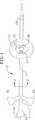
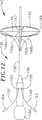
例えば、図1および2に例示されるように、本発明の好ましい実施形態によるカテーテル10は、生体適合性の熱可塑性材料(例えば、編み組み、または非編み組みのPebax(登録商標)(ポリエーテルブロックエミド)、ポリエチレン、またはポリウレタン)から形成され得、そして好ましくは約5フレンチ〜約9フレンチの直径である、可塑性カテーテル本体12を備える。好ましくは、このカテーテル本体12は、比較的短い可塑性遠位部材(非編み組みPebax(登録商標)からなる)、およびより長く可塑性に乏しい近位部材(編み組みPebax(登録商標)からなる)からなる2つの部分の構築物を有する。近位部材および遠位部材は、重複熱接着で一緒に接着され得るか、またはスリーブにわたって端と端を一緒に接着性に結合され得る(これは「バット接着(butt bond)と呼ばれる」)。カテーテル本体12の近位端は、ハンドル14に固定される。拡張可能(そして折りたたみ可能)凝固体16は、カテーテル本体12の遠位端付近に装着される。以下に記載のように、拡張可能凝固体16は、この凝固体に接触した軟部組織が凝固する温度に加熱され得る。
【0025】
拡張可能凝固体16(カテーテル本体12の周囲に結合されそして配置される)は、水、高張性塩溶液、または他の生体適合性液で膨張させられ得る。この液体は、注入/排気ポート18を通じて圧力下でカテーテル10に供給される。圧力をかけられた液体は、カテーテル本体12内の液体管腔20、および拡張可能凝固体内に配置される装置22を通じて拡張可能凝固体16と往復する。圧力は、図1に例示される拡張された方向に、拡張可能凝固体16を維持するように維持される。この圧力は、相対的に低く(5psi未満)、そして膨張の所望のレベル、用いた材料の強度、および本体の可塑性の所望の程度によって変化する。この液体は、注入/排気ポート18に吸引力を加えることにより、拡張可能凝固体16から除去され得る。
【0026】
肺静脈においてまたはその周囲の病変の作成に関連した適用について、例示的な拡張可能凝固体16は好ましくは、カテーテル本体12の遠位先端から約3cm〜約5cmに配置され、そしてこの直径は、折り畳み状態で約2mm〜約6mmの間、そして拡張状態(すなわち膨張状態)で約10mm〜約30mmの間である。拡張可能凝固体16に適切な材料は、比較的伸縮性の熱伝導性の生体適合性材料(例えば、シリコーンおよびポリイソプレン)を含む。他の伸縮性に乏しい材料(例えば、ナイロン(登録商標)、Pebax(登録商標)、ポリエチレンおよびポリエステル)がまた用いられ得る。ここで、拡張可能凝固体は、折り畳み線で形成されなければならない。[図6に例示した例示的実施形態に関する折り畳み線に関して、以下の考察に注意のこと。]さらに、例示的な拡張可能凝固体16は、球状形状を有するが、他の形状(例えば、液滴形状、円柱状形状、または幅広楕円形状)がまた、使用され得る。
【0027】
液体加熱エレメントは、拡張可能凝固体16内に配置される。図1および2に例示される好ましい実施形態において、液体加熱エレメントは、カテーテル本体12上に装着された電極24である。あるいは、両極性対の電極が、伝導性液体(例えば、前述の等張性塩溶液)を通じてパワー(電力)を伝達して熱を発生するために用いられ得る。この液体の温度は、約90℃に加熱され得、これにより拡張可能凝固体16の外側の温度は、組織凝固のための温度とほぼ同じ温度まで上昇する。この電極は、金属(例えば、プラチナ(白金)、金、およびステンレス鋼)から形成され得る。
【0028】
拡張可能凝固体16は、比較的表層の病変を生じるようである。従って、肺静脈内で病変を生成するために特に有用である。
【0029】
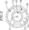
この液体の温度は、好ましくは、出力制御の目的でモニターされる。そのためには、温度検知エレメント(例えば、例示された熱電対26)が、拡張可能凝固体16内のカテーテル12上に装着され得る。参照熱電対28は、カテーテル12の遠位端付近に配置され得る。あるいは、サーミスタまたは他の温度検知エレメントが、熱電対および参照熱電対の配列の代わりに用いられ得る。電極24、熱電対26および参照熱電対28は、それぞれ電気伝導体32、34および36(これはカテーテル本体中の伝導体管腔38を通じて伸びる)によって電気コネクター30に接続される。コネクター30は、適切なRF電源装置および制御装置に接続され得る。
【0030】
図1および2に例示される例示的カテーテル本体12はまた、中央ポート42と結合する中央管腔40を備える。中央管腔の目的は、本質的に二重である。中央管腔40は、プローブ10が目的の身体領域(例えば、肺静脈)に指向されている場合、ガイドワイヤ管腔として働く。ガイドワイヤ44は、従来の様式で体の領域にまず指向され、ついでプローブ10がこのガイドワイヤを超えて前進する。比較的短い導入シースを用いて血管へのカテーテル10の挿入を容易にし得る。あるいは、目的の解剖領域に伸長するシースを用い得る。一旦、このプローブが目的の身体領域に到達すれば、ガイドワイヤ44は、この管腔が、その管腔の他の目的(別のデバイスの身体領域への通過を提供すること)のために用いられ得るように取り除かれ得る。
【0031】
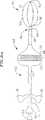
図3に例について図示されるように、従来のバスケットカテーテル46(例えば、EP Technologies,Inc.(San Jose,California)により製造されるConstellation(登録商標)バスケットカテーテル)は、中心管腔40を通って前進され得る。例示的なバスケットカテーテル46は、細長カテーテル本体48、マッピングおよび/または凝固バスケット50ならびにハンドル/電気コネクター52を備える。このバスケットは、2〜8個の電極支持スプライン54および各スプライン上に1〜8個の電極56を備え得る。これらのスプライン54は、好ましくは弾力のある生物学的不活性な材料(例えば、Nitinol(登録商標)金属、ステンレス鋼またはシリコーンゴム)から作製され、これらは、バスケット50の長手方向軸の周りに対称または非対称のいずれかで配置され得る。これらのスプライン54は、基部部材58と末端キャップ60との間に、弾力のある予め引っ張った(pretensed)半径方向に拡張した状態で接続されて屈曲し、そしてそれらが接触している心内組織表面に適合する。
【0032】
図3に図示される例示的なバスケット50は、そのペーシングおよびマッピングのために肺静脈中に挿入されることを意図され、これは、それぞれ2つの電極56を支持する4つのスプライン54を備える。バスケット50はまた、実質的に楕円形を有し、そして拡張した状態で約20mmと約40mmとの間の直径であり、かつ5cmの長さである。バスケット構造体に関するさらなる詳細は、米国特許第5,823,189号に開示される。
【0033】
例示的カテーテル10とバスケットカテーテル46との組合せは、医師が単一の装置を用いてマッピング手順および凝固手順を実行することを可能にし、それにより、上述の当該分野における問題を排除する。さらに、バスケット50は、凝固手順の間に肺静脈または他の開口部内に位置付けられ得、そしてアンカーとして拡張可能凝固本体16の配置の正確さを改善するように作用し得る。バスケットが存在しない例において、カテーテル本体の遠位部分は、アンカーとして作用し得る。
【0034】
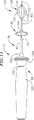
本発明に従う別の例示的なカテーテルは、図4〜6に図示され、そして概して参照数字62で表わされる。カテーテル62は、多くの様式で図1〜3に図示されるカテーテルに類似しており、同様の要素は、同様の参照数字で表わされる。しかし、2つの主要な差異が存在する。カテーテル62は、加熱されて拡張可能な凝固本体16と反対に、拡張可能(かつ折り畳み可能)な多孔性電極構造体64を備え、そして電極支持バスケット50は、中心管腔40を通って前進される別個のカテーテル上に装着されることと反対に、カテーテル本体12の遠位部分上に装着される。
【0035】
図5に例として示されるように、拡張可能な多孔性電極64(これは、非電導性熱可塑性材料またはエラストマー材料から形成される)は、孔68および2つの無孔性領域70および72を有する多孔性領域66を備える。孔68(これは、実際にはミクロポアである)は、説明の目的のために、拡大された形で模式的に示される。液圧を使用して、拡張可能な多孔性電極64を膨張させ、その拡張した状態に維持する。この液体(これは、注入/通気ポート18および流体管腔20(図2)を通って供給され、開口22により拡張可能多孔性電極64に入る。拡張可能多孔性電極64は、次いでその折り畳まれた低プロファイル状態(約2.3mmと約5.3mmとの間の直径)から、その拡張した状態(約10mmと約30mmとの間)に拡張する。
【0036】
比較的高い電導性および比較的高い熱伝導性の両方を有する材料から形成される電極24は、拡張可能な多孔性電極64内に運ばれる。適切な材料としては、金、白金、および白金/イリジウムが上げられる。貴金属が好ましい。ここでも、電極24、熱電対および参照熱電対28は、電気導線32、34および36によって電気コネクター30に接続され、これらの導線は、カテーテル本体12における導線管腔38を通って接続される(図2に注目)。拡張可能な多孔性電極64を満たすために使用される液体は、電導性液体であり、これは、電極24から組織へRFエネルギーを運搬するための電導性経路を確立する。
【0037】
孔68は、電極24から電導性流体を通って、多孔性電極64の外側の組織への組織凝固エネルギーのイオン性輸送を確立する。この液体は、好ましくは、多孔性電極64内でのオーム損失(すなわちオーム加熱効果)を低減するために低い抵抗を有する。電導性液体の組成は変化し得る。飽和または飽和に近い塩化ナトリウム濃度を有する高張生理食塩水溶液(約20%重量/容積)が好ましい。高張生理食塩水溶液は、約150ohm・cmの血液の抵抗および約500ohm・cmの心筋組織抵抗と比較して、わずか約5ohm・cmの低い抵抗を有する。あるいは、この流体は、高張性塩化カリウム溶液であり得る。この媒体は、所望のイオン性輸送を促進するが、カリウムの過負荷を防ぐために、孔68を通るイオン輸送が起こる速度をより密な間隔でモニタリングする必要がある。高張性塩化カリウム溶液が使用される場合、イオン輸送速度を約1mEq/分より下に維持することが好ましい。
【0038】
イオン対照(control)溶液(本来低い抵抗を有する)は、高張性塩化ナトリウムまたは塩化カリウムの溶液と混合され得る。この混合物は、孔68を通るイオンの移行を減少することなく、多孔性電極64のラジオグラフ同定を可能にする。
【0039】
孔68を横切る大量の濃度差に大いに起因して、伝導性液体中のイオンは、濃度差駆動拡散のために、孔中へと進む。孔68を通るイオン拡散は、濃度勾配が多孔性電極64を横切って維持される限り持続する。孔68中に含有されるイオンは、多孔性電極64を横切る電流を導く手段を提供する。RFエネルギーがRF電源および制御装置から電極24に運ばれる場合、電流は、孔68内のイオンにより運ばれる。これらのイオンにより提供されるRF電流は、DC電圧が印加される場合に起こるように、イオンの正味の拡散を生じないが、これらのイオンは、そしてRF周波数の印加の間にわずかに前後に移動する。印加されたRF場に応じたイオンの移動(および電流の流れ)は、孔68を通る液体の潅流を必要としない。これらのイオンは、RFエネルギーを、孔68を通って組織中に戻り(return)電極へと運び、この戻り電極は、代表的には外部パッチ電極(単極配置を形成する)である。あるいは、伝達されたエネルギーは、隣接する電極(双極配置を形成する)へと組織を通過し得る。RFエネルギーは、組織を(主に抵抗により(ohmically))加熱して、組織を凝固させ、そして外傷を形成する。
【0040】
拡張可能電極64の好ましい幾何学は、本質的にティアドロップ形状をしており、そして無孔性領域により囲まれる孔68の環と対称である。この環は、好ましくは約2mm〜約10mmの幅である。この多孔性電極構成は、特に、比較的深い外傷を肺静脈への入り口の周りに形成するために有用である。しかし、非対称または非ティアドロップ形状の幾何学が使用され得る。多孔性電極は、例えば、球形状で形成され得る。細長の円筒形幾何学はまた、使用され得る。遠位無孔性領域72は、排除され得、そして多孔性領域と置き換えられる。多孔性領域66の形状および大きさもまた変化させ得る。
【0041】
材料に関して、拡張可能な多孔性電極64の多孔性領域66は、好ましくは、再生セルロースまたは微孔性弾性ポリマーから形成される。レーザー、静電放電、イオンビーム衝撃または他のプロセスの使用により生成されるミクロポアを有する含水性材料もまた使用され得る。無孔性領域は、好ましくは、比較的弾性の材料(例えば、シリコーンおよびポリイソプレン)から形成される。しかし、他のより低い弾性の材料(例えば、Nylon(登録商標)、Pebax(登録商標)、ポリエチレン、ポリエステルウレタンおよびポリエステル)もまた使用され得る。ここで、拡張可能な多孔性電極64は、例えば図6に図示されるように、多孔性電極の折り畳みを容易にするしわの付いた領域74を備え得る。親水性被覆は、鞘の内外への多孔性電極64の移動を容易にするために無孔性領域に適用され得る。
【0042】
図1〜3に図示される例示的なカテーテル10と同様に、例示的カテーテル62は、このカテーテルを比較的短い導入器鞘を通って、そしてガイドワイヤ44上で前進させることにより、目的の解剖学的部位(例えば、肺静脈)に向けられ得る。しかし、バスケット50はカテーテルの遠位端上に取り付けられるので、基部部材58および末端キャップ60は、ガイドワイヤ44が通って延びる開口を備える。比較的短い導入器鞘を使用して、カテーテル62の脈管構造への挿入を促進し得るか、あるいは目的の解剖学的領域に延びる鞘が使用され得る。
【0043】
図1〜3に図示される例示的カテーテル10が、カテーテル本体12の遠位端上に固定して取り付けられるバスケットを備え得ることに留意すべきである。このようなカテーテルは、図3aにおいて参照数字10’で同定される。同様に、バスケットは、別個のバスケットカテーテルが、図3に図示される様式と同様の様式でバスケットと組み合わせて使用され得るように、図4〜6に図示されるカテーテル62から取り外され得る。このようなカテーテルは、図6aにおいて参照数字46’で同定される。
【0044】
拡張可能かつ折り畳み可能な本体のさらなる情報および例は、「Devices and Methods for Creating Lesions in Endocardial and Surrounding Tissue to Isolate Arrhythmia Substrates」と題する米国特許出願番号第08/984,414号、米国特許第5,368,591号および米国特許第5,961,513号に開示される。
【0045】
(III.フープ構造体)
図7〜10の例について図示されるように、本明細書中の本発明に従うカテーテル76は、カテーテル本体78を備え、このカテーテル本体78は、遠位端においてまたは遠位端の近傍で折り畳み可能なフープ構造体80を支持する。このフープ構造体80を使用して、環状組織領域(例えば、肺静脈)と接触した1つ以上の手術要素を支持し得る。例えば、フープ構造体80を使用して、複数の間隔を空けられた電極82を支持し得る。例示的な折り畳み可能なフープ構造体80は、実質的に円形のフープスプライン84、一対の遠位支持スプライン86および一対の近位支持スプライン88を備える。フープスプライン84の形状は、あるいは、長円形、楕円形または特定の適用に必要な任意の他の2次元もしくは3次元形状であり得る。各支持スプライン86および88の末端は、ループ89を備え、このループは、図9に図示される様式で、フープスプライン84の対応する部分を取り囲む。フープスプライン84の周囲の周りでの、支持スプライン86および88の過剰な移動は、電極82により防止される。
【0046】
例示的な折り畳み可能フープ構造体80は、遠位支持スプライン86および近位支持スプライン88を互いに離して移動することにより、図7に図示される拡張された配向から、図8に図示される折り畳み配向へ駆動され得る。図示された実施形態において、カテーテル本体78は、近位支持スプライン86および遠位支持スプライン88をこの様式で移動するように構成される。より詳細には、カテーテル本体78は、一対のカテーテル本体部材90および92を備え、これらは、互いに対して移動可能である。カテーテル本体部材90および92は、好ましくは、部材92が部材90の管腔内に滑動可能に受容されるように配置される管状部材である。遠位支持スプライン86は、カテーテル本体部材90に固定され、一方、近位支持スプライン88は、カテーテル本体部材92に固定される。カテーテル本体部材92がカテーテル本体部材90に対して近位方向に移動される場合、遠位支持スプライン86および近位支持スプライン88は、互いに離れて移動されて、フープ構造体80を折り畳む。反対方向の相対移動は、支持構造を拡張する。もちろん、カテーテル本体部材92は、カテーテル本体部材90に対して移動され得、または両方のカテーテル本体部材は、本発明の他の実施において移動され得る。
【0047】
図7〜10に図示される例示的な実施形態において、遠位支持スプライン86および近位支持スプライン88は、カテーテル本体部材90およびカテーテル本体部材92に、アンカーリング94および96を用いて固定される。遠位支持スプライン86および近位支持スプライン88は、好ましくは、アンカーリング94および96にスポット溶接され、そしてこのアンカーリングは、好ましくは、カテーテル本体部材90および92に接着剤で接着される。他の結合方法もまた使用され得る。
【0048】
フープスプライン84、遠位支持スプライン86および近位支持スプライン88は、好ましくは弾力性の、生物学的に不活性な材料(例えば、Nitinol(登録商標)金属、ステンレス鋼または弾性ポリマー(例えば、シリコーンゴム)から作成される。これらのスプラインは、拡張されたフープ構造体80に対応する形状に予め成形される。肺静脈適用に適切な実施において、フープスプライン84は、約10mm〜約30mmの直径である。カテーテル本体部材90および92は、生体適合性熱可塑性材料(例えば、ブレードもしくは非ブレードのPebax(登録商標)、ポリエチレン、またはポリウレタン)から形成され得る。肺静脈適用に適切な実施において、このカテーテル本体部材90は、約1.5mmの外径、および約1mmの内径を有し、一方、カテーテル本体部材92は、約2.2mmの外径および約1.6mmの内径を有する。
【0049】
スプラインは、好ましくは、生体適合性ポリマー材料(例えば、Pebax(登録商標)もしくはNylon(登録商標))から形成される管で覆われる。電極82および温度センサ83のための導線ワイヤ(示されず)(以下のIV節において議論される)は、管を通過し、そしてカテーテル本体部材90の管腔に入る。
【0050】
典型的なカテーテル76はまた、互いに対してカテーテル本体部材90および92を移動し得る、ハンドル98を備える。図10をさらに詳細に参照すると、典型的なハンドル98は、電極82および温度センサ83からの導線ワイヤのための適切な電気接続部(示していない)を有するハンドル本体100、ハンドル本体において長手方向に伸長している開口において滑動可能に取りつけられたピストン102、ならびにつまみレスト104を備える。このハンドル本体100、ピストン102およびつまみレスト104は、好ましくは機械加工プラスチックまたは成形プラスチックから形成される。このカテーテル本体部材92は、接着剤または他の適切な手段を用いてつまみレスト104上のひずみ解放要素105に固定される。このカテーテル本体部材90は、カテーテル本体部材92を通り、ピストン102において形成される管腔を通り、そしてハンドル本体100の近位部分中に伸長する。このカテーテル本体部材90は、アンカー106に接着されるか、さもなければ固定され、アンカー106それ自体は、固定ねじ108または他の適切なデバイスで適所に保持される。このカテーテル本体部材90の位置は、ハンドル100に対して固定され、そしてピストン102および近位カテーテル本体部材92はハンドルに対して固定されないため、カテーテル本体部材92は、ピストンを動かすことでカテーテル本体部材90に対して移動され得る。
【0051】
図7、8および10に図示される典型的なハンドル98におけるピストン102は、一度ピストンが折り畳みフープ構造体80に対応する位置に配置されると動かないことを確実にするために、固定ねじ110が、ピストンにおいて形成されるキー溝112と係合する。固定ねじ110とキー溝112との間の摩擦力は、折り畳みフープ構造体80によって生じる力に打ち勝つのに十分である。さらに、ピストンのキー溝112の長手方向の縁は、固定ねじ110と係合することによってピストン102の作動範囲を制限する。好ましい実施形態において、キー溝112の長さは、約0.75インチ(1.9cm)であるが、約0.375インチから約1.5インチ(1.0〜3.8cm)の範囲であり得る。さらに、好ましい実施形態は上記の固定ねじおよびキー溝構成を備えるが、ピストンに摩擦力を加え、そしてピストンの作動範囲を制限するための他の機構もまた用いられ得る。例えば、ピストンの作動範囲を制限するための溝ひだ、テーパ状コレット、以下で議論されるものに加えてOリング、または周囲ピストングリップが、好ましいねじおよびキー溝構成の代わりに使用され得る。
【0052】
例示的なハンドル98はまた、直接向けられた付勢力をピストン102に適用する圧縮スプリング114を備える。この付勢力は、ピストン102を遠位方向に移動させ、そしてフープ構造体80を拡張するために、医師によりピストン102に適用しなければならない力の量を減少させる。圧縮スプリング114は、ピストン102の近位端と環状形態の迫持台116との間に配置される。圧縮スプリング114によってピストン102に付与される付勢力のために、ピストンを駆動するのに必要とされる、医師が加える作用力の量が、減少する。
【0053】
一対のOリング118は、例示的なハンドル98のハンドル本体100内にピストン102を作製するために使用され得る。このOリング118はまた、ピストンが傾斜するのを防ぐ。キーウェイ114と反対の例示的ピストン102の側部は、一対のTeflon(登録商標)ロッド120を備え、これは、ハンドル本体100において、長手軸方向に延びる開口部の表面上に存在する。このTeflon(登録商標)ロッド120は、改良された潤滑性を提供し、そしてセットスクリュー110がピストン102を開口部の表面に駆動するのを妨げる。
【0054】
例示的なカテーテル76は、ガイドワイヤ122(カテーテル本体部材90の内部ルーメン内に配置される)を越えて、通常の様式で目的の本体領域に進められ得る。比較的短い導入鞘または目的の解剖学的領域に延びる鞘が、所望の場合に使用され得る。次いで、フープ構造体80が、拡張され得、そして例えば、肺静脈にまたは肺静脈内の入口に環状管腔を作製するために使用され得る。さらに、電極82または他の作動的要素がフープスプライン84上に取り付けられ、組織凝固が、血流の閉塞なしで達成され得る。
【0055】
カテーテル本体部材90の内部管腔はまた、別のデバイス用の本体領域への通過を提供するために使用され得る。図11に例のために例示されるように、従来のバスケットカテーテル124(例えば、EP Technologies,Inc.in Sun Jose,Californiaによって製造されたConstellantion(登録商標)バスケットカテーテル)は、遠位カテーテル部材90の管腔を介して進められ得る。このバスケットカテーテル124は、示されるようにガイドワイヤ122上を進められ得るか、このガイドワイヤは、バスケットカテーテルの挿入前に、カテーテル本体部材中の管腔から取り除かれ得る。
【0056】
例示的なバスケットカテーテル124は、細長カテーテル本体126、マッピングおよび/または凝固バスケット128ならびにハンドル/電気コネクター(示さず)を備える。図3を参照すると、上記のバスケット50のように、例示的バスケット128は、4つの対称的に配列されたスプライン129を備え、これは、好ましくは、弾力的な生物学的挿入材料(例えば、Nitinol(登録商標)材料、ステンレス鋼またはシリコーンゴム)から作製される。各スプライン129は、2個の電極130を支持し、そしてベース部材132と末端キャップ134との間の弾性的な半径方向に拡張した状態で支持される。バスケットカテーテル124は、肺静脈内での使用のために構成され、そして実質的に楕円状の形状を有し、そして拡張状態で約20mmと約40mmとの間の直径であり、そして折り畳み状態で約5cmの長さである。それにもかかわらず、スプラインの数および各スプライン上の電極、ならびにバスケット128の全サイズは、適用が必要な場合に、増加または減少され得る。
【0057】
組合されたカテーテル76およびバスケットカテーテル124は、医者が、単一の用具を用いてマッピングおよび凝固手順を実施するのを可能にし、従って、当該分野において、上記の問題を排除する。このバスケットはまた、フープ構造体80の配置の精度を改善するためのアンカーとして使用され得る。
【0058】
図11aにおける例のために例示されるように、他にカテーテル76と同一であるカテーテル76’は、カテーテル本体部材90の遠位端と一体となったバスケット128’を備え得る。ここで、ハンドル100はまた、バスケット128’のための適切な電気コネクターを備える。
【0059】
一般的に参照番号136によって示される折り畳みフープ構造体を備える別の例示的なカテーテルは、図12〜14に例示される。このカテーテルは、折り畳みフープ構造体140を支持するカテーテル本体138を備える。このフープ140は、肺静脈のような環状組織領域と接触した1以上の作動的要素を支持するために使用され得る。例えば、フープ構造体140を使用して、間隔を空けた複数の電極142を支持し得る。例示的なフープ構造体140は、実質的に環状フープスプライン144および4つの半径方向に延びた支持スプライン146を備える。あるいは、フープスプライン144の形状は、特定の適用のために必要とされる、卵型、楕円または特定の適用のために必要とされる任意の他の形状であり得る。支持スプライン146は溶接され、そうでなければ、カテーテル本体138上に取り付けられたアンカーリング147に確保される。このアンカーリング147は、インターフェースフィット、接着剤またはそれらの組合せの代わりに保持され得る。
【0060】
第1対スタイレット148aおよび148bならびに第2対スタイレット150aおよび150bは、例示的フープスプライン144に装着される。この末端支持スプライン146ならびにスタイレット148a、148b、150aおよび150bは、図13に例示された様式で、フープスプライン144の対応する部分を取り囲む各々のループ152を備える。スタイレット148a、148bおよび150a、150bは、カテーテル本体138内の管腔に、開口部154を介して延び、そしてスタイレット148および150の各々の対に巻き付けられる。
【0061】
カテーテル本体138および支持スプライン146は、図7〜11に例示される好ましい実施形態において、それらのカウンターパートと同一の材料から形成され得る。特に、支持スプライン146は、好ましくは、Nitinol(登録商標)材料、ステンレス鋼または弾性ポリマーから形成され、そしてこのアンカーリング147は、支持スプラインと同一の材料から形成されるべきである。このスタイレット148a、148b、150aおよび150bは、Nitinol(登録商標)または17−7スレテンレス鋼ワイヤのような不活性ワイヤから形成され得る。このカテーテルはまた、スタイレット、電極および温度センサを連結する導体、ならびにガイドワイヤのための管腔を備える。
【0062】
例示的カテーテル136はまた、ハンドル156を備える。この創傷したスタイレット対148および150は、ハンドル開口部158および160を通過し、そしてスタイレット対の近位端は、グリッド162および164で提供される。この例示的フープ構造体140は、遠位方向にスタイレット148(およびスタイレット148および148b)を移動させ、そして近位方向にスタイレット対150(およびスタイレット150aおよび150b)を移動させることによって、図12に例示された拡張配向から図14に例示された折り畳み配向に駆動され得る。あるいは、このハンドルは、従来の双方向ステアリング開口部(例えば、米国特許第5,254,088号に例示された回転可能のノブ配置、または米国特許第5,364,351号に例示された回転可能ギアおよびロック配置)で提供され得、スタイレット対148および150を反対方向に駆動する。任意の事象において、ハンドル156はまた、好ましくは、電気コネクター166を備える。
【0063】
例示的カテーテル136は、カテーテル本体部材138中の管腔を通過するガイドワイヤを越えて進められ得る。比較的短い導入鞘または目的の解剖学的領域に延びる鞘が、所望の場合に使用され得る。次いで、ここもまた、フープ構造体140は拡張され得、そして血流を閉塞することなく環状外傷を作製するために使用され得る。
【0064】
図12−14に例示される例示的カテーテルはまた、マッピングバスケットと組合せて使用され得る。図14aの例のために例示されるように、図11に例示されるようなバスケットカテーテル124は、カテーテル136のガイドワイヤ管腔を通過して進められ得る。あるいは、図14bにおける例のために例示されるように、改良されたカテーテル136’は、カテーテル138の遠位端状に装着されたバスケット128’を備える。
【0065】
外傷作製カテーテルの他のタイプは、一体型マッピングバスケットと共に提供され得る。図15の例のために例示されるように、例示的カテーテル168は、近位部分170、螺旋状遠位部分172および一体型マッピング/凝固バスケット174を備える。螺旋状遠位部分172は、好ましくは、複数の電極176を支持する。螺旋状部分172の回転数、長さ、直径および形状は、適用に対して変化する。肺静脈中またはその周りに外傷を作製するために使用され得る、図15に例示される螺旋状部分は、弛緩した状態で、カテーテル168の長手軸の周りを、1よび1と1/2回回転する。上記のものと本質的に同一であるバスケット174は、4つのスプライン178および各スプライン上に一対の電極180を備える。他のバスケットの形状は、必要とされる適用として使用され得る。
【0066】
例示的なカテーテル168はまた、医者が、螺旋状部分172を操作し、そしてその形状を調節し得る。スタイレット182の遠位部分は、螺旋状遠位部分172のカテーテル遠位部分の領域内で固定して確保される。このスタイレット182は、遠位および近位に移動され得、そして螺旋状部分を巻き戻して、その直径を減少させるか、または直径を減少させる他の方向に回転される。任意のこれらの状態において、螺旋状部分は、血液または他の体液が流れ得る電極176内の開口領域を規定する。結果として、螺旋状部分は、流体流無しで、肺静脈内または肺静脈または他の体の開口部の周りに周囲の外傷を作製するために使用され得る。
【0067】
図15に例示された例示的カテーテル168は、操作可能なカテーテルではなく、従って、標的位置に従来の操作可能なガイド鞘を介して進められ得る。この鞘は、潤滑性であり、カテーテル168の移動の間の摩擦を減少させる。鞘中にカテーテル168を進める前に、このスタイレット182は、螺旋状遠位部分172を真直ぐにするために、最も遠位部分まで移動させ、そして保持する。このスタイレット182は、螺旋状遠位部分172が鞘の遠位端を越えて進められるまでこの位置に保持する。バスケットカテーテルと組合せて使用されるような鞘導入は、カテーテルを鞘に導入する場合に使用され得る。
【0068】
図15に例示された螺旋状カテーテルに関係するさらなる情報は、マッピングバスケットを有さないが、現在出願されており、そして一般に譲渡された米国出願番号09/447,186(表題「Loop Structures For Supporting Diagnostic and Therapeutic Elements in Contact With Body Tissu」)で開示されている。
【0069】
フープ構造体を有する別の例示的カテーテルは、図16〜18に例示されている。まず図16に言及すると、このカテーテル184は、カテーテル本体186およびその遠位端に折り畳みフープ構造体188を備える。このフープ構造体188は、肺静脈のような環状組織領域と接触して、例示された電極190のような、1以上の操作的要素を支持するために使用され得る。例示的フープ構造体188は、実質的に環状フープスプライン192および4つの支持スプライン194を備える。このフープスプライン192はまた、卵型、楕円または任意の他の形状であり得、そして支持スプライン194の数は、適用が必要な場合に増加または減少され得る。肺静脈適用のために適切な実行において、フープスプライン192は、約10mm〜約30mmの直径である。
【0070】
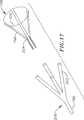
図17および18に例のために例示されるように、この例示的なフープ構造体188は、4つの実質的に同一の構造体部材196から構成され、これらの各々は、一対の支柱198および約90°延びる湾曲部200、ならびにカテーテル本体186から外側に延びる4つの形成チューブ202からなる。この目的のために、支柱198は、ベンド204で形成され、その結果、この支柱は、カテーテル本体186の遠位部分およびそこから外側に延びるチューブ202を備える、領域206の形状に一致する。従って、各支持スプライン194は、2本の支柱198および成形チューブ202からなる複合構造体である。電極(示さず)に関連する電極190および温度センサから繋ぐことにより、チューブ202から、カテーテル本体186と通って延びる管腔へ通過する。
【0071】
構造部材196は、好ましくは、Nitinol(登録商標)金属、ステンレス鋼、またはシリコーンゴムのような弾性的な生物学的に不活性な材料から形成され、これは、拡張したフープ構築物188に対応する形状に予め形成される。このカテーテル本体186および成形チューブ202は、生体適合性材料(例えば、網目状または非網目状のPebax(登録商標)、ポリエチレン、またはポリウレタン)から形成され得る。
【0072】
比較的短い導入鞘および、好ましくは、目的の解剖学的領域に延びる鞘が、図16〜18に例示される例示的なカテーテルと結合して使用される。ここでもまた、フープ構築物は拡張され、そして血流を閉塞することなく肺静脈にまたは肺静脈内に環状外傷を作製するために使用され得る。
【0073】
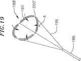
図19において例のために例示されるように、図16〜18において例示される、例示的なフープ構造体188は、構造体の折り畳み可能性を増強させるためにわずかに再構成され得る。例示的なフープ構造体188’は、構造部材196の形状を別として、フープ構造体188と本質的に同一である。ここで、フープ構造体188’の湾曲部200’は、フープ構造体188の湾曲部200に対して矢印「A」の方向に遠位に回転され、折り畳み可能性を増加させる。
【0074】
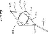
さらに別の例示的なフープ構造体は、図20に例示され、そして一般に参照番号208によって示される。ここで、このカテーテルは、カテーテル本体210およびその遠位端において折り畳み可能なフープ構造体212で提供される。このフープ構造体212は、肺静脈のような環状組織領域と接触して、例示された電極214のような1以上の作動的要素を支持するために使用され得る。例示的なフープ構造体212は、実質的に環状フープスプライン216、4つの近位支持スプライン218、4つの遠位支持スプライン220、ベース222および末端キャップ224を備える。さらなる構造的な支持体を提供することに加えて、遠位支持スプライン220は、組織凝固手順の間にアンカーとして作用する。このフープスプライン214は、肺静脈適用のために適切な実施において約10mm〜約30mmの直径である。このフープスプライン216はまた、卵型、楕円または任意の他の形状であり得、そして支持スプライン218、220の数は、適用が必要である場合に、増加または減少され得る。
【0075】
(IV.フープ構造体電極、温度検出および出力制御)
好ましい実施形態の各々において、作動的要素は、複数の間隔を空けた電極である。しかし、他の作動的電極(例えば、化学的消耗部、レザーアレイ、超音波変換器、マイクロ波電極、および比較的加熱したワイヤ)、ならびにこのようなデバイスは、この電極と置換され得る。さらに、電極および温度センサは、図7−11を参照して記載される例示的カテーテルの文脈において以下で議論され、この議論はまた、図12〜20を参照して記載される例示的カテーテルに適用可能である。
【0076】
間隔を空けた電極82は、好ましくは、巻き付けられた螺旋状コイルの形態である。このコイルは、銅アレイ、白金、もしくはステンレス鋼のような伝導性材料、または巻き込まれた充填チューブのような複合体(例えば、白金ジャケットを含む銅コア)から電気的に作製される。このコイルの伝導性材料は、伝導性および生体適合を改良するために、白金−イリジウム、または金でさらにコーティングされ得る。好ましいコイル電極は、米国特許第5,797,905号に開示される。電極82は、電気的に個々のワイヤ(例えば、図2に例示されるワイヤ)に接続され、ワイヤにエネルギーを凝固する。このワイヤを、関連するカテーテル本体を介して、カテーテルハンドルのPCボードに延びる管腔を、従来の様式で通過させ、ここで、これらは、ハンドルのポートに受容されるコネクターに電気的に連絡される。このコネクターは、RF凝固エネルギーの供給源にプラグする。
【0077】
代替として、電極は、白金のような伝導性材料の固体環状部の形態であり得るか、または白金−イリジウムまたは金のような伝導性材料を含み得、これらは、従来のコーティング技術またはイオンビーム補助堆積(ion beam assisted deposition)(IBAD)プロセスを使用して、デバイス上にコーティングされる。よりよい付着のために、ニッケルまたはチタンのアンダーコーティングが塗布され得る。この電極はまた、螺旋状リボンの形態であり得る。この電極はまた、非伝導性管状本体状にプリントされたパッドである、従来のインク化合物で形成され得る。好ましい伝導性インク化合物は、銀ベース合成接着伝導性インク(ポリウレタンバインダー)であるが、他の金属ベース接着伝導性インク(例えば、白金ベース、金ベース、銅ベースなど)がまた使用されて、電極を形成し得る。このようなインクは、エポキシベースインクよりもより可撓性である。
【0078】
この可撓性電極82は、好ましくは、約4mm〜約20mmの長さである。好ましい実施形態において、この電極は、1mm〜3mmの間隔を空けた12.5mmの長さであり、この結果として、凝固エネルギーが隣接する電極に同時に適用される場合、連続した外傷パターンを組織中に作製する。硬質電極のために、各電極の長さは、約2mm〜約10mmで変化し得る。逆に、各々約10mmよりも長い複数の硬質電極を使用することは、このデバイスの全体の可撓性に影響を与える一方で、約2mm未満の長さを有する電極は、所望の連続的外傷パターンを一貫として形成しない。
【0079】
組織と接触することが意図されない(そして血液プールに曝露される)電極の一部は、好ましくは、電気的および熱的に遮断されている材料で、種々の技術を介してマスクされ得る。これにより、凝固エネルギーを血液プールに直接的に伝達することを防ぎ、そして組織の方へ直接的にエネルギーを向ける。例えば、UV接着剤(または別の接着剤)の層は、電極の予め選択された部分上にプリントされ、組織と接触することが意図されない電極の一部を絶縁し得る。堆積技術はまた、組織と接触すると意図されるアセンブリのこれらの部分上にのみ、伝導性表面を位置決めするように実施される。あるいは、コーティングは、PTFE材料中の電極を浸漬することによって形成され得る。
【0080】
この電極は、単極モードで操作され得、電極によって発光された軟部組織凝固エネルギーが、患者の皮膚に外部から接着された不活性パッチ電極(示さず)を介して戻される。あるいは、この電極は、双極モードで操作され得、1以上の電極によって発光されたエネルギーは、他の電極を介して戻される。凝固組織に必要とされる出力の量は、5〜150Wの範囲である。
【0081】
図9の例のために例示されるように、複数の温度センサ83(例えば、熱伝対またはサーミスター)が、電極82のまたは電極82間の長手軸端エッジに隣接して、上部または下部に配置され得る。好ましくは、この温度センサ83は、フープ構造体または螺旋状構造体の側部に遠位で面している、電極82の長手軸エッジに配置されている。いくつかの実施形態において、参照熱伝対(示さず)がまた提供され得る。温度コントロールの目的のために、温度センサからの信号が、カテーテルハンドル中の上記のPCボードに接続されるワイヤ(例えば、図2に例示されるワイヤ)によって凝固エネルギーの供給源に伝達される。適切な温度センサ、感知した温度に基づいて電極への出力を制御するコントローラーが、米国特許第5,456,682号、同第5,582,609号および同第5,755,715号に開示される。
【0082】
最後に、電極82および温度センサ83は、多孔性材料コーティングを備え、これは、電化されたイオン媒体を介して凝固エネルギーを伝達する。例えば、米国特許第5,991,650号に開示されるように、電極および温度センサは、再生セルロース、ヒドロゲルまたは伝導性成分を有するプラスチックでコーティングされ得る。再生セルロースに関して、このコーティングは、外科的デバイス成分(例えば、血球、病原菌(例えば、ウイルスおよび細菌)ならびに巨大な生物学的分子(例えば、タンパク質)の侵入を防ぐが、人体との電気的な接触を提供する電極)の間の機械的障害として作用する。再生セルロースコーティングはまた、デバイス成分と人体との間の生物学的障害として作用し、これによって、この成分が、ここで、いくらか毒性がある材料(例えば、銀または銅)から作製され得る。
【0083】
本発明は、上記の好ましい実施形態の用語、上記好ましい実施形態の複数の改変体および/または付加物は、当業者に容易に明らかとなる。本発明の範囲は、このような改変体および/または付加物の全てに及ぶこと、ならびに本発明の範囲は、下記の特許請求の範囲によって単に限定されることが意図される。
【図面の簡単な説明】
本発明の好ましい実施形態の詳細な説明は、添付の図面を参照してなされる。
【図1】 図1は、本発明の好ましい実施形態によるプローブの側面断面図である。
【図2】 図2は、図1の線2−2に沿った断面図である。
【図3】 図3は、マッピングバスケットを支持するプローブと組み合わせた、図1に例示されるプローブの断面図である。
【図3a】 図3aは、一体型マッピングバスケットを備える図1に例示されるプローブと類似のプローブの側面図である。
【図4】 図4は、本発明の好ましい実施形態によるプローブの側面図である。
【図5】 図5は、図4に例示されるプローブの一部の断面図である。
【図6】 図6は、図4に例示される多孔性電極の側面図であり、ここには追加された折り畳み線を有する。
【図6a】 図6aは、図4に例示されるプローブと類似のプローブの側面図であり、別のプローブ上に装着されたマッピングバスケットを備える。
【図7】 図7は、本発明の好ましい実施形態によるプローブの側面図である。
【図8】 図8は、図7に例示されるプローブの折り畳み配向の部分的側面図である。
【図9】 図9は、図7に例示されるプローブの一部の部分的透視図である。
【図10】 図10は、図7に例示される、プローブハンドルの側面の部分的断面図である。
【図11】 図11は、マッピングバスケットを支持するプローブと組み合わせた、図7に例示されるプローブの側面図である。
【図11a】 図11aは、一体型マッピングバスケットを備える、図7に例示されるプローブと類似のプローブの側面図である。
【図12】 図12は、本発明の好ましい実施形態によるプローブの側面図である。
【図13】 図13は、図12に例示されるプローブの一部の部分的透視図である。
【図14】 図14は、折り畳み配向の、図12に例示されたプローブの側面図である。
【図14a】 図14aは、マッピングバスケットを支持するプローブと組み合わせた図12に例示されるプローブの側面図である。
【図14b】 図14bは、一体型マッピングバスケットを備える、図12に例示されるプローブと類似のプローブの側面図である。
【図15】 図15は、本発明の好ましい実施形態によるプローブの側面図である。
【図16】 図16は、本発明の好ましい実施形態によるプローブの透視図である。
【図17】 図17は、図16に例示されるプローブにおける特定のエレメントを示す分解透視図である。
【図18】 図18は、図16および図17に例示される輪状構造を形成する構造部材の1つの透視図である。
【図19】 図19は、本発明の好ましい実施形態によるプローブの透視図である。
【図20】 図20は、本発明の好ましい実施形態によるプローブの透視図である。[0001]
(Background of the Invention)
(1. Field of the Invention)
The present invention relates generally to medical devices that support one or more diagnostic or therapeutic elements in contact with body tissue, and more particularly, one or more diagnostic or therapeutic elements to a body opening or the like. It is related with the medical device which contacts and supports the structure | tissue around the opening part.
[0002]
(2. Explanation of related fields)
There are numerous examples where diagnostic and therapeutic elements must be inserted into the body. One example includes the treatment of heart conditions such as atrial fibrillation and atrial flutter, which lead to unpleasant irregular heartbeats (called arrhythmias).
[0003]
The normal sinus rhythm of the heart begins with a sinoatrial node (or “SA node”) that generates an electrical impulse. This impulse usually propagates evenly across the left and right atrium and the atrial septum and into the atrioventricular node (or “AV node”). This propagation causes the atria to contract in an organized manner that transports blood from the atria to the ventricles and provides timed ventricular stimulation. AV nodules slowly regulate propagation to the atrioventricular bundle (or “HIS bundle”). This synchronization of the electrical activity of the heart causes atrial contraction during ventricular diastole. This in turn improves the mechanical function of the heart. Atrial fibrillation occurs when anatomical disturbances in the heart disrupt the normally uniform propagation of electrical shock within the atrium. These anatomical obstacles (referred to as “conduction blocks”) can transform electrical shocks into several round waves, which circulate around the obstacle. These waves are called “reentrant circuits” and disrupt the normally uniform activation of the left and right atria.
[0004]
Due to the loss of atrioventricular synchrony, people suffering from atrial fibrillation and atrial flutter also suffer from hemodynamic deficits and loss of heart efficiency. They are also at higher risk of stroke and other thromboembolic complications due to loss of effective contraction and atrial congestion.
[0005]
One surgical method for treating atrial fibrillation by interrupting the path of the reentry circuit is the so-called “maze procedure”, which is for electrical propagation in the left and right atria. Relies on the prescribed pattern of incisions to create the tortuous path (ie, the maze) by dissection. This incision directs the electrical shock from the SA node through all areas of both atria along a specific path, causing the uniform contraction required for normal atrial transport function. These incisions finally direct the impact to the AV node to activate the ventricles and restore normal atrioventricular synchrony. These incisions are also carefully positioned to interrupt the conduction path of the most common reentry circuit. This maze procedure has been found to be very effective in healing atrial fibrillation. However, the maze procedure is technically difficult to implement. This also requires open heart surgery and is very expensive.
[0006]
Create trauma to the endocardium (the trauma is 1-15 cm in length and of various shapes) to effectively create a labyrinth for electrical conduction in a predetermined path A maze-like procedure that utilizes a catheter could also be developed. The formation of these traumas by soft tissue coagulation (also called “resection”) can provide the same therapeutic benefits as the complex incision pattern currently offered by surgical maze procedures, but without invasive open heart surgery. Not accompanied.
[0007]
Catheters used to create trauma typically include a relatively long and relatively flexible body portion that has a soft tissue coagulation electrode and / or a distal end at its distal end. A series of tissue coagulation electrodes spaced apart near the distal end. The portion of the catheter body that is inserted into the patient is typically 23 to 55 inches (58.4 to 139.7 cm) long and includes a handle separately on the outside of the patient. There may be ˜15 inches (20.3-38.1 cm). The length and flexibility of the catheter body is such that the catheter is inserted into the main vein or artery (typically the femoral artery), directed into the heart, and then a coagulation electrode is placed on the tissue to be excised. Allows to be manipulated to touch. A fluoroscopic image is used to provide the surgeon with a visual indication of the position of the catheter.
[0008]
In some examples, the proximal end of the catheter body is connected to a handle that includes a manipulation control device. An exemplary catheter of this type is disclosed in US Pat. No. 5,582,609. In other examples, the catheter body is inserted into the patient through the sheath, and the distal portion of the catheter is bent into a loop extending outwardly from the sheath. This can be accomplished by pivotally securing the distal end of the catheter to the distal end of the sheath, as described in US Pat. No. 6,071,729. As the catheter is pushed distally, a loop is formed. This loop can also be formed by securing a pull wire to the distal end of the catheter that extends backward through the sheath, as described in US Pat. No. 5,910,129. Loop catheters are advantageous in that they tend to conform to different tissue contours and structures and are intimately spaced between tissue coagulation electrodes (or other diagnostic or therapeutic elements) and tissue Provide contact.
[0009]
A mapping basket (which may be provided at the distal end of a separate mapping catheter) is often used to place a reentry path prior to trauma formation. An exemplary mapping basket is disclosed in US Pat. No. 5,823,189. Furthermore, once a trauma has been formed, this mapping basket is again used to determine whether the trauma has successfully eliminated its reentry path. The mapping basket is superior to conventional diagnostic catheters. Because the mapping basket does not need to be manipulated at various locations within the body region (eg, pulmonary veins) during the diagnostic procedure, and instead in a single beat from a single trauma A procedure may be performed.
[0010]
However, the use of mapping catheters in combination with soft tissue coagulation catheters can be problematic. For example, when a mapping catheter is used in combination with a soft tissue coagulation catheter, a pair of septal penetrating punctures (or relatively), so that the catheter can be advanced from the right atrium through the foveal fossa to the left atrium. A large single puncture) must be formed in the atrial septum. Two punctures (or a relatively large single puncture) must also be made in the femoral vein. Furthermore, the time required to operate the two catheters into their respective positions can lead to an extended period of fluoroscopy.
[0011]
Nevertheless, the problem with the combined use of mapping and coagulation catheters is that one trauma that has proven difficult to form using conventional catheters isolates pulmonary veins and is ectopic. It is a surrounding trauma that is used to heal atrial fibrillation. Trauma that isolates the pulmonary veins can be formed within the pulmonary vein itself or in tissue surrounding the pulmonary vein. Conventional steerable and loop catheters have been shown to be less effective with respect to the formation of such surrounding trauma. Specifically, it is difficult to form an effective surrounding trauma by forming a pattern of trauma with a relatively small diameter.
[0012]
Thus, herein, the inventors have determined that there is a need for a device that is capable of both tissue mapping and coagulation. Herein, the inventors have further determined that there is generally a need for structures that can be used to create surrounding trauma inside or around a body opening. Herein, the inventors have also determined that there is a need for a device that can map the pulmonary veins and create trauma in or around the pulmonary veins.
[0013]
(Summary of the Invention)
Therefore, a general object of the present invention is to provide a device that avoids the above problems for implementation purposes. In particular, one object of the present invention is to provide a device that can be used to create other body openings in a more effective manner than surrounding openings and conventional openings in or around the pulmonary veins. Another object of the present invention is to provide a device that can be used both to map the pulmonary veins and to create trauma in or around the pulmonary veins.
[0014]
To achieve some of these and other objectives, a probe according to one embodiment of the present invention comprises a support, an expandable / foldable tissue coagulation structure supported on the support, and A mapping structure is provided. The mapping structure is supported on a distal support of the expandable / foldable tissue coagulation structure, or passes through a lumen in the support and advances beyond the distal end of the support. Can be. Such a probe provides several advantages over conventional openings. For example, the combination of the tissue coagulation structure and the mapping structure allows the physician to perform the mapping and coagulation procedures using a single tool, eliminating the above problems in the art. This mapping structure can be placed in the pulmonary vein or other opening during the coagulation procedure and serves as an anchor to improve the correct placement of the coagulation structure. In addition, the expandable tissue coagulation structure is particularly useful for creating annular trauma within and around pulmonary veins and other body openings.
[0015]
To achieve these and other objectives, a probe according to one embodiment of the present invention comprises a support that defines a longitudinal axis, an open internal region and is expandable / supported on the support. A foldable hoop structure, comprising at least one actuating element supported on the expandable / foldable hoop structure. Such a probe offers several advantages over conventional devices. For example, in an implementation in which the actuating element consists of a plurality of spaced electrodes, the hoop structure is easily positioned so that the electrodes are in contact with tissue inside or around the pulmonary vein or other body opening. Can be done. The hoop structure also defines an open area that allows blood or other bodily fluids to pass through the open area. As a result, the probe of the present invention facilitates the formation of surrounding trauma without the problems associated with conventional openings and without clogging of blood or other fluids.
[0016]
The above features and advantages of the invention, as well as many other features and advantages, will be apparent when the invention is considered better in conjunction with the accompanying drawings and by reference to the following detailed description. .
[0017]
Detailed Description of Preferred Embodiments
The following is a detailed description of the presently known best mode for carrying out the invention. This description should not be taken in a limiting sense, but is merely for the purpose of illustrating our general principles.
[0018]
The detailed description of the preferred embodiment is organized as follows:
I. Introduction (Introduction)
II. Inflatable structure (inflatable structure)
III. Ring-shaped structure
IV. Annular structure electrode, temperature detection process and power supply control device.
[0019]
The general organization of the title of this section and the detailed description of the invention is for convenience only and is not intended to limit the invention.
[0020]
I. Introduction (Introduction)
The present invention can be used in body cavities, tufts or cavities for diagnostic or therapeutic purposes. In this case, access to the body cavity region is obtained, for example, through the vasculature or gastrointestinal tract and without complicated invasive surgical procedures. For example, the invention described herein has application in the diagnosis and treatment of arrhythmia conditions in the heart. The invention described herein also has application in the diagnosis or treatment of diseases of the gastrointestinal tract, prostate, brain, bladder, uterus, and other body regions.
[0021]
With respect to the treatment of intracardiac conditions, the present invention is designed to produce intimate tissue contact with the target substrate associated with various arrhythmias (ie, atrial fibrillation, atrial flutter, and ventricular tachycardia). The For example, the distal portion of a catheter according to the present invention, which may comprise diagnostic electrodes and / or tissue coagulation electrodes, causes lesions in or around pulmonary veins to treat ectopic atrial fibrillation Can be used.
[0022]
This structure is also adaptable for use with probes other than catheter-based probes. For example, the structures disclosed herein can be used in conjunction with a hand-held surgical device (ie, a “surgical probe”). The distal end of the surgical probe can be placed in direct contact with the targeted tissue region by a physician during a surgical procedure (eg, open heart surgery). Here, access may be achieved by thoracotomy, median sternotomy, or thoracotomy. An exemplary surgical probe is disclosed in US Pat. No. 6,071,281.
[0023]
A surgical probe device according to the present invention preferably comprises a handle, a relatively short shaft, and one of the distal assemblies described hereinbelow (in the case of a catheter). Preferably, the length of the shaft is from about 4 inches to about 18 inches (10.2-45.7 cm). This is relatively short compared to the catheter body (typically 23 to 55 inches long (58.4 to 139.7 cm)) inserted into the patient and the additional body portion remaining outside the patient. This shaft is also relatively stiff. In other words, the shaft is either rigid, malleable, or somewhat plastic. A rigid shaft cannot be bent. A malleable shaft is a shaft that can be easily bent by a physician into the desired shape without springing back when released, so that the shaft remains in shape during the surgical procedure . Thus, the stiffness of the malleable shaft is low enough (soft) to allow the shaft to be bent, but resists bending when forces related to the surgical procedure are applied to the shaft. Must be high enough (hard) to do. The somewhat plastic shaft is bent and then bounces when released. However, the force required to bend this shaft is quite necessary.
[0024]
(II. Inflatable structure)
For example, as illustrated in FIGS. 1 and 2, a
[0025]
The expandable coagulum 16 (coupled and disposed around the catheter body 12) can be inflated with water, a hypertonic salt solution, or other biocompatible fluid. This liquid is supplied to the
[0026]
For applications related to the creation of lesions in or around the pulmonary veins, the exemplary
[0027]
The liquid heating element is disposed within the expandable solidified
[0028]
The
[0029]
The temperature of this liquid is preferably monitored for power control purposes. To that end, a temperature sensing element (eg, the illustrated thermocouple 26) can be mounted on the
[0030]
The
[0031]
As illustrated for example in FIG. 3, a conventional basket catheter 46 (eg, a Constellation® basket catheter manufactured by EP Technologies, Inc. (San Jose, California)) passes through the
[0032]
The
[0033]
The combination of the
[0034]
Another exemplary catheter according to the present invention is illustrated in FIGS. 4-6 and is generally represented by the
[0035]
As shown by way of example in FIG. 5, the expandable porous electrode 64 (which is formed from a non-conductive thermoplastic or elastomeric material) includes a
[0036]
An
[0037]
The
[0038]
An ionic control solution (which inherently has low resistance) can be mixed with a solution of hypertonic sodium chloride or potassium chloride. This mixture allows radiographic identification of the
[0039]
Significantly due to the large concentration difference across the
[0040]
The preferred geometry of the
[0041]
With respect to material, the
[0042]
Similar to the
[0043]
It should be noted that the
[0044]
Further information and examples of expandable and foldable bodies can be found in U.S. Patent No. 4, U.S. Pat. No. 4, U.S. Pat. No. 4, U.S. Pat. 368,591 and US Pat. No. 5,961,513.
[0045]
(III. Hoop structure)
As illustrated for the example of FIGS. 7-10, a
[0046]
The exemplary
[0047]
In the exemplary embodiment illustrated in FIGS. 7-10,
[0048]
The
[0049]
The spline is preferably covered with a tube formed from a biocompatible polymeric material (eg, Pebax® or Nylon®). Conductor wires (not shown) for
[0050]
The
[0051]
In order to ensure that the
[0052]
The
[0053]
A pair of O-
[0054]
The
[0055]
The internal lumen of the
[0056]
The
[0057]
The combined
[0058]
As illustrated for the example in FIG. 11 a, a
[0059]
Another exemplary catheter comprising a folded hoop structure generally indicated by
[0060]
[0061]
[0062]
The
[0063]
The
[0064]
The exemplary catheter illustrated in FIGS. 12-14 can also be used in combination with a mapping basket. As illustrated for the example of FIG. 14 a, the
[0065]
Other types of trauma catheters can be provided with an integral mapping basket. As illustrated for the example of FIG. 15,
[0066]
The
[0067]
The
[0068]
Further information relating to the helical catheter illustrated in FIG. 15 does not have a mapping basket, but is currently filed and commonly assigned US application Ser. No. 09 / 447,186 (title “Loop Structures For Supporting”). Diagnostic and Therapeutic Elements in Contact With Body Tissue ").
[0069]
Another exemplary catheter having a hoop structure is illustrated in FIGS. Referring first to FIG. 16, the
[0070]
As illustrated by way of example in FIGS. 17 and 18, this
[0071]
The
[0072]
A relatively short introducer sheath, and preferably a sheath that extends to the anatomical region of interest, is used in conjunction with the exemplary catheter illustrated in FIGS. Again, the hoop construct is dilated and can be used to create an annular trauma in or into the pulmonary vein without occluding the blood flow.
[0073]
As illustrated by way of example in FIG. 19, the
[0074]
Yet another exemplary hoop structure is illustrated in FIG. 20 and generally indicated by
[0075]
(IV. Hoop structure electrode, temperature detection and output control)
In each of the preferred embodiments, the operative element is a plurality of spaced electrodes. However, other working electrodes (eg, chemical consumables, laser arrays, ultrasonic transducers, microwave electrodes, and relatively heated wires), and such devices can be replaced with this electrode. In addition, electrodes and temperature sensors are discussed below in the context of the exemplary catheter described with reference to FIGS. 7-11, and this discussion is also discussed in the exemplary catheter described with reference to FIGS. Applicable.
[0076]
The spaced apart
[0077]
Alternatively, the electrode may be in the form of a solid annulus of a conductive material such as platinum, or may include a conductive material such as platinum-iridium or gold, which may be a conventional coating technique or ion beam. It is coated on the device using an ion beam assisted deposition (IBAD) process. A nickel or titanium undercoating can be applied for better adhesion. The electrode can also be in the form of a spiral ribbon. The electrode can also be formed of a conventional ink compound, which is a pad printed on a non-conductive tubular body. The preferred conductive ink compound is a silver-based synthetic adhesive conductive ink (polyurethane binder), but other metal-based adhesive conductive inks (eg, platinum-based, gold-based, copper-based, etc.) can also be used to Can be formed. Such inks are more flexible than epoxy-based inks.
[0078]
The
[0079]
The part of the electrode that is not intended to come into contact with the tissue (and exposed to the blood pool) is preferably masked via various techniques with a material that is electrically and thermally blocked. This prevents the transfer of coagulation energy directly to the blood pool and directs the energy directly towards the tissue. For example, a layer of UV adhesive (or another adhesive) can be printed on a preselected portion of the electrode to insulate a portion of the electrode that is not intended to contact tissue. Deposition techniques are also performed to position the conductive surface only on those portions of the assembly that are intended to come into contact with the tissue. Alternatively, the coating can be formed by immersing the electrode in PTFE material.
[0080]
The electrode can be operated in monopolar mode, and soft tissue coagulation energy emitted by the electrode is returned through an inert patch electrode (not shown) that is externally adhered to the patient's skin. Alternatively, the electrode can be operated in bipolar mode, and the energy emitted by one or more electrodes is returned through the other electrode. The amount of power required for the solidified tissue is in the range of 5-150W.
[0081]
As illustrated for the example of FIG. 9, a plurality of temperature sensors 83 (eg, thermocouples or thermistors) are located on the upper or lower side of the
[0082]
Finally,
[0083]
The present invention will be readily apparent to those skilled in the art from the above preferred embodiment terminology, multiple variants and / or additions of the preferred embodiment. It is intended that the scope of the invention extends to all such modifications and / or adjuncts, and that the scope of the invention be limited only by the claims that follow.
[Brief description of the drawings]
The detailed description of the preferred embodiments of the present invention is made with reference to the accompanying drawings.
FIG. 1 is a side cross-sectional view of a probe according to a preferred embodiment of the present invention.
FIG. 2 is a cross-sectional view taken along line 2-2 of FIG.
FIG. 3 is a cross-sectional view of the probe illustrated in FIG. 1 in combination with a probe that supports a mapping basket.
FIG. 3a is a side view of a probe similar to the probe illustrated in FIG. 1 with an integrated mapping basket.
FIG. 4 is a side view of a probe according to a preferred embodiment of the present invention.
FIG. 5 is a cross-sectional view of a portion of the probe illustrated in FIG.
FIG. 6 is a side view of the porous electrode illustrated in FIG. 4 with an additional fold line.
6a is a side view of a probe similar to the probe illustrated in FIG. 4, comprising a mapping basket mounted on another probe. FIG.
FIG. 7 is a side view of a probe according to a preferred embodiment of the present invention.
FIG. 8 is a partial side view of the folding orientation of the probe illustrated in FIG.
FIG. 9 is a partial perspective view of a portion of the probe illustrated in FIG.
FIG. 10 is a partial cross-sectional view of the side of the probe handle illustrated in FIG.
FIG. 11 is a side view of the probe illustrated in FIG. 7 in combination with a probe that supports a mapping basket.
FIG. 11a is a side view of a probe similar to the probe illustrated in FIG. 7 with an integral mapping basket.
FIG. 12 is a side view of a probe according to a preferred embodiment of the present invention.
FIG. 13 is a partial perspective view of a portion of the probe illustrated in FIG.
FIG. 14 is a side view of the probe illustrated in FIG. 12 in a folded orientation.
FIG. 14a is a side view of the probe illustrated in FIG. 12 in combination with a probe that supports a mapping basket.
FIG. 14b is a side view of a probe similar to the probe illustrated in FIG. 12 with an integrated mapping basket.
FIG. 15 is a side view of a probe according to a preferred embodiment of the present invention.
FIG. 16 is a perspective view of a probe according to a preferred embodiment of the present invention.
FIG. 17 is an exploded perspective view showing specific elements in the probe illustrated in FIG. 16;
FIG. 18 is a perspective view of one of the structural members that form the ring-shaped structure illustrated in FIGS. 16 and 17. FIG.
FIG. 19 is a perspective view of a probe according to a preferred embodiment of the present invention.
FIG. 20 is a perspective view of a probe according to a preferred embodiment of the present invention.
Claims (38)
Translated fromJapanese支持体;
該支持体上に支持される、拡張可能/折り畳み可能組織凝固構造体;および
該拡張可能/折り畳み可能組織凝固構造体の遠位において、該支持体上に支持される、拡張可能/折り畳み可能マッピングバスケット、
を備える、プローブ。A probe, the following:
Support;
An expandable / foldable tissue coagulation structure supported on the support; and an expandable / foldablemapping supported on the support distal to the expandable / foldable tissue coagulation structure. basket,
Comprising a probe.
前記膨張可能構造体の前記内部に位置する、流体加熱要素、
を備える、請求項5に記載のプローブ。In addition:
A fluid heating element located within the interior of the inflatable structure;
The probe according to claim 5, comprising:
前記膨張可能構造体の前記内部に位置する、電極、
を備える、請求項7に記載のプローブ。In addition:
An electrode located in the interior of the inflatable structure;
The probe according to claim 7, comprising:
組織凝固プローブであって、以下:
少なくとも1つの内部管腔を規定する、組織凝固プローブ支持体、および
該組織凝固プローブ支持体上に支持される、拡張可能/折り畳み可能組織凝固構造体、
を備える、組織凝固プローブ;ならびに
該組織凝固プローブ支持体の管腔を通過し得る、マッピングプローブであって、以下:
マッピングプローブ支持体、および
該マッピングプローブ支持体上に支持される、拡張可能/折り畳み可能マッピングバスケット、
を備える、マッピングプローブ、
を備える、マッピングおよび組織凝固装置。Mapping and coagulation device, the following:
A tissue coagulation probe, the following:
A tissue coagulation probe support defining at least one internal lumen, and an expandable / foldable tissue coagulation structure supported on the tissue coagulation probe support;
A tissue coagulation probe; and a mapping probe capable of passing through the lumen of the tissue coagulation probe support, comprising:
A mapping probe support and an expandable / foldablemapping basket supported on the mapping probe support;
A mapping probe comprising:
A mapping and tissue coagulation device comprising:
前記膨張可能構造体の前記内部に位置する、流体加熱要素、
を備える、請求項24に記載のマッピングおよび凝固装置。In addition:
A fluid heating element located within the interior of the inflatable structure;
25. The mapping and coagulation device according to claim 24.
前記膨張可能構造体に前記内部に位置する、電極、
を備える、請求項26に記載のマッピングおよび凝固装置。In addition:
An electrode located inside the inflatable structure,
27. The mapping and coagulation device according to claim 26, comprising:
Applications Claiming Priority (3)
| Application Number | Priority Date | Filing Date | Title |
|---|---|---|---|
| US09/447,182US6529756B1 (en) | 1999-11-22 | 1999-11-22 | Apparatus for mapping and coagulating soft tissue in or around body orifices |
| US09/447,182 | 1999-11-22 | ||
| PCT/EP2000/011640WO2001037746A1 (en) | 1999-11-22 | 2000-11-22 | Apparatus for mapping and coagulating soft tissue in or around body orifices |
Publications (2)
| Publication Number | Publication Date |
|---|---|
| JP2003514612A JP2003514612A (en) | 2003-04-22 |
| JP4627948B2true JP4627948B2 (en) | 2011-02-09 |
Family
ID=23775326
Family Applications (1)
| Application Number | Title | Priority Date | Filing Date |
|---|---|---|---|
| JP2001539363AExpired - Fee RelatedJP4627948B2 (en) | 1999-11-22 | 2000-11-22 | Device for mapping and coagulating soft tissue inside or around a body opening |
Country Status (8)
| Country | Link |
|---|---|
| US (4) | US6529756B1 (en) |
| EP (1) | EP1233718B1 (en) |
| JP (1) | JP4627948B2 (en) |
| AT (1) | ATE336956T1 (en) |
| CA (1) | CA2394816C (en) |
| DE (1) | DE60030315T2 (en) |
| ES (1) | ES2269214T3 (en) |
| WO (1) | WO2001037746A1 (en) |
Families Citing this family (499)
| Publication number | Priority date | Publication date | Assignee | Title |
|---|---|---|---|---|
| US5697882A (en) | 1992-01-07 | 1997-12-16 | Arthrocare Corporation | System and method for electrosurgical cutting and ablation |
| US7175619B2 (en)* | 1994-10-07 | 2007-02-13 | Boston Scientific Scimed, Inc. | Loop structures for positioning a diagnostic or therapeutic element on the epicardium or other organ surface |
| US6805130B2 (en)* | 1995-11-22 | 2004-10-19 | Arthrocare Corporation | Methods for electrosurgical tendon vascularization |
| US7220257B1 (en)* | 2000-07-25 | 2007-05-22 | Scimed Life Systems, Inc. | Cryotreatment device and method |
| US7027869B2 (en) | 1998-01-07 | 2006-04-11 | Asthmatx, Inc. | Method for treating an asthma attack |
| US6634363B1 (en) | 1997-04-07 | 2003-10-21 | Broncus Technologies, Inc. | Methods of treating lungs having reversible obstructive pulmonary disease |
| US7992572B2 (en) | 1998-06-10 | 2011-08-09 | Asthmatx, Inc. | Methods of evaluating individuals having reversible obstructive pulmonary disease |
| US7425212B1 (en)* | 1998-06-10 | 2008-09-16 | Asthmatx, Inc. | Devices for modification of airways by transfer of energy |
| US6488673B1 (en)* | 1997-04-07 | 2002-12-03 | Broncus Technologies, Inc. | Method of increasing gas exchange of a lung |
| US6610055B1 (en) | 1997-10-10 | 2003-08-26 | Scimed Life Systems, Inc. | Surgical method for positioning a diagnostic or therapeutic element on the epicardium or other organ surface |
| US7921855B2 (en) | 1998-01-07 | 2011-04-12 | Asthmatx, Inc. | Method for treating an asthma attack |
| US6837885B2 (en) | 1998-05-22 | 2005-01-04 | Scimed Life Systems, Inc. | Surgical probe for supporting inflatable therapeutic devices in contact with tissue in or around body orifices and within tumors |
| US8181656B2 (en)* | 1998-06-10 | 2012-05-22 | Asthmatx, Inc. | Methods for treating airways |
| US7198635B2 (en) | 2000-10-17 | 2007-04-03 | Asthmatx, Inc. | Modification of airways by application of energy |
| US7276063B2 (en) | 1998-08-11 | 2007-10-02 | Arthrocare Corporation | Instrument for electrosurgical tissue treatment |
| US6702811B2 (en) | 1999-04-05 | 2004-03-09 | Medtronic, Inc. | Ablation catheter assembly with radially decreasing helix and method of use |
| US20010007070A1 (en)* | 1999-04-05 | 2001-07-05 | Medtronic, Inc. | Ablation catheter assembly and method for isolating a pulmonary vein |
| US7226446B1 (en) | 1999-05-04 | 2007-06-05 | Dinesh Mody | Surgical microwave ablation assembly |
| US6277113B1 (en) | 1999-05-28 | 2001-08-21 | Afx, Inc. | Monopole tip for ablation catheter and methods for using same |
| US6306132B1 (en) | 1999-06-17 | 2001-10-23 | Vivant Medical | Modular biopsy and microwave ablation needle delivery apparatus adapted to in situ assembly and method of use |
| US7426409B2 (en)* | 1999-06-25 | 2008-09-16 | Board Of Regents, The University Of Texas System | Method and apparatus for detecting vulnerable atherosclerotic plaque |
| US6529756B1 (en) | 1999-11-22 | 2003-03-04 | Scimed Life Systems, Inc. | Apparatus for mapping and coagulating soft tissue in or around body orifices |
| US6645199B1 (en)* | 1999-11-22 | 2003-11-11 | Scimed Life Systems, Inc. | Loop structures for supporting diagnostic and therapeutic elements contact with body tissue and expandable push devices for use with same |
| US7033352B1 (en) | 2000-01-18 | 2006-04-25 | Afx, Inc. | Flexible ablation instrument |
| US8251070B2 (en) | 2000-03-27 | 2012-08-28 | Asthmatx, Inc. | Methods for treating airways |
| US6673068B1 (en) | 2000-04-12 | 2004-01-06 | Afx, Inc. | Electrode arrangement for use in a medical instrument |
| US6652517B1 (en)* | 2000-04-25 | 2003-11-25 | Uab Research Foundation | Ablation catheter, system, and method of use thereof |
| WO2001082814A2 (en) | 2000-05-03 | 2001-11-08 | C.R. Bard, Inc. | Apparatus and methods for mapping and ablation in electrophysiology procedures |
| US6640120B1 (en)* | 2000-10-05 | 2003-10-28 | Scimed Life Systems, Inc. | Probe assembly for mapping and ablating pulmonary vein tissue and method of using same |
| US7104987B2 (en) | 2000-10-17 | 2006-09-12 | Asthmatx, Inc. | Control system and process for application of energy to airway walls and other mediums |
| US6916306B1 (en)* | 2000-11-10 | 2005-07-12 | Boston Scientific Scimed, Inc. | Steerable loop structures for supporting diagnostic and therapeutic elements in contact with body tissue |
| US7785323B2 (en) | 2000-12-04 | 2010-08-31 | Boston Scientific Scimed, Inc. | Loop structure including inflatable therapeutic device |
| US20020087151A1 (en) | 2000-12-29 | 2002-07-04 | Afx, Inc. | Tissue ablation apparatus with a sliding ablation instrument and method |
| DE10105592A1 (en) | 2001-02-06 | 2002-08-08 | Achim Goepferich | Placeholder for drug release in the frontal sinus |
| US20030181940A1 (en)* | 2001-02-28 | 2003-09-25 | Gregory Murphy | Ventricular restoration shaping apparatus and method of use |
| US6743195B2 (en)* | 2001-03-14 | 2004-06-01 | Cardiodex | Balloon method and apparatus for vascular closure following arterial catheterization |
| US7175734B2 (en) | 2001-05-03 | 2007-02-13 | Medtronic, Inc. | Porous medical catheter and methods of manufacture |
| US6771996B2 (en)* | 2001-05-24 | 2004-08-03 | Cardiac Pacemakers, Inc. | Ablation and high-resolution mapping catheter system for pulmonary vein foci elimination |
| US20040243118A1 (en)* | 2001-06-01 | 2004-12-02 | Ayers Gregory M. | Device and method for positioning a catheter tip for creating a cryogenic lesion |
| US7485088B2 (en)* | 2001-09-05 | 2009-02-03 | Chase Medical L.P. | Method and device for percutaneous surgical ventricular repair |
| US20040243170A1 (en)* | 2001-09-05 | 2004-12-02 | Mitta Suresh | Method and device for percutaneous surgical ventricular repair |
| US20050004441A1 (en)* | 2001-10-11 | 2005-01-06 | Chen Peter C. | System and methods for locating and ablating arrhythomogenic tissues |
| US8974446B2 (en)* | 2001-10-11 | 2015-03-10 | St. Jude Medical, Inc. | Ultrasound ablation apparatus with discrete staggered ablation zones |
| US6671533B2 (en)* | 2001-10-11 | 2003-12-30 | Irvine Biomedical Inc. | System and method for mapping and ablating body tissue of the interior region of the heart |
| US20070038056A1 (en)* | 2001-10-11 | 2007-02-15 | Carlo Pappone | System and methods for locating and ablating arrhythomogenic tissues |
| US6669693B2 (en)* | 2001-11-13 | 2003-12-30 | Mayo Foundation For Medical Education And Research | Tissue ablation device and methods of using |
| US7785324B2 (en)* | 2005-02-25 | 2010-08-31 | Endoscopic Technologies, Inc. (Estech) | Clamp based lesion formation apparatus and methods configured to protect non-target tissue |
| US7753908B2 (en)* | 2002-02-19 | 2010-07-13 | Endoscopic Technologies, Inc. (Estech) | Apparatus for securing an electrophysiology probe to a clamp |
| US7099717B2 (en) | 2002-01-03 | 2006-08-29 | Afx Inc. | Catheter having improved steering |
| US7192427B2 (en)* | 2002-02-19 | 2007-03-20 | Afx, Inc. | Apparatus and method for assessing transmurality of a tissue ablation |
| US6932816B2 (en)* | 2002-02-19 | 2005-08-23 | Boston Scientific Scimed, Inc. | Apparatus for converting a clamp into an electrophysiology device |
| DE60225343T2 (en)* | 2002-02-22 | 2009-02-19 | Bombardier Recreational Products Inc., Valcourt | 3-WHEELED VEHICLE WITH TWO-WAY COOLER AND INTERIOR STORAGE BOX |
| GB0205109D0 (en)* | 2002-03-05 | 2002-04-17 | Thermocore Medical Systems Sa | A catheter |
| US7653438B2 (en) | 2002-04-08 | 2010-01-26 | Ardian, Inc. | Methods and apparatus for renal neuromodulation |
| US20140018880A1 (en) | 2002-04-08 | 2014-01-16 | Medtronic Ardian Luxembourg S.A.R.L. | Methods for monopolar renal neuromodulation |
| US8774913B2 (en) | 2002-04-08 | 2014-07-08 | Medtronic Ardian Luxembourg S.A.R.L. | Methods and apparatus for intravasculary-induced neuromodulation |
| US6752767B2 (en) | 2002-04-16 | 2004-06-22 | Vivant Medical, Inc. | Localization element with energized tip |
| US7197363B2 (en) | 2002-04-16 | 2007-03-27 | Vivant Medical, Inc. | Microwave antenna having a curved configuration |
| US7008418B2 (en)* | 2002-05-09 | 2006-03-07 | Stereotaxis, Inc. | Magnetically assisted pulmonary vein isolation |
| AUPS226502A0 (en)* | 2002-05-13 | 2002-06-13 | Advanced Metal Coatings Pty Limited | A multi-electrode lead |
| US7510560B2 (en)* | 2002-06-20 | 2009-03-31 | Tyco Healthcare Group Lp | Method and apparatus for anastomosis including an anchoring sleeve |
| US6932829B2 (en)* | 2002-06-24 | 2005-08-23 | Cordis Corporation | Centering catheter |
| US7357799B2 (en)* | 2002-06-27 | 2008-04-15 | Depuy Acromed, Inc. | Thermal coagulation using hyperconductive fluids |
| US6866662B2 (en)* | 2002-07-23 | 2005-03-15 | Biosense Webster, Inc. | Ablation catheter having stabilizing array |
| US8317816B2 (en) | 2002-09-30 | 2012-11-27 | Acclarent, Inc. | Balloon catheters and methods for treating paranasal sinuses |
| US20050033137A1 (en)* | 2002-10-25 | 2005-02-10 | The Regents Of The University Of Michigan | Ablation catheters and methods for their use |
| US20040082947A1 (en)* | 2002-10-25 | 2004-04-29 | The Regents Of The University Of Michigan | Ablation catheters |
| US7156816B2 (en)* | 2002-11-26 | 2007-01-02 | Biosense, Inc. | Ultrasound pulmonary vein isolation |
| US20060267255A1 (en)* | 2003-01-31 | 2006-11-30 | Daniela Tomova | Process for producing a performance enhanced single-layer blow-moulded container |
| US7115127B2 (en) | 2003-02-04 | 2006-10-03 | Cardiodex, Ltd. | Methods and apparatus for hemostasis following arterial catheterization |
| US7223266B2 (en)* | 2003-02-04 | 2007-05-29 | Cardiodex Ltd. | Methods and apparatus for hemostasis following arterial catheterization |
| US8021359B2 (en)* | 2003-02-13 | 2011-09-20 | Coaptus Medical Corporation | Transseptal closure of a patent foramen ovale and other cardiac defects |
| US6923808B2 (en) | 2003-02-24 | 2005-08-02 | Boston Scientific Scimed, Inc. | Probes having helical and loop shaped inflatable therapeutic elements |
| EP1605875A3 (en)* | 2003-03-03 | 2005-12-28 | Sinus Rhythm Technologies, Inc. | Electrical block positioning devices and methods of use therefor |
| WO2004078065A2 (en)* | 2003-03-03 | 2004-09-16 | Sinus Rhythm Technologies, Inc. | Electrical conduction block implant device |
| US20040186467A1 (en)* | 2003-03-21 | 2004-09-23 | Swanson David K. | Apparatus for maintaining contact between diagnostic and therapeutic elements and tissue and systems including the same |
| US7293562B2 (en)* | 2003-03-27 | 2007-11-13 | Cierra, Inc. | Energy based devices and methods for treatment of anatomic tissue defects |
| US20040226556A1 (en) | 2003-05-13 | 2004-11-18 | Deem Mark E. | Apparatus for treating asthma using neurotoxin |
| WO2005009213A2 (en) | 2003-07-16 | 2005-02-03 | Arthrocare Corporation | Rotary electrosurgical apparatus and methods thereof |
| US7311703B2 (en) | 2003-07-18 | 2007-12-25 | Vivant Medical, Inc. | Devices and methods for cooling microwave antennas |
| DE202004021953U1 (en) | 2003-09-12 | 2013-06-19 | Vessix Vascular, Inc. | Selectable eccentric remodeling and / or ablation of atherosclerotic material |
| DE10345023A1 (en)* | 2003-09-24 | 2005-04-21 | Biotronik Gmbh & Co Kg | Ablation catheter, comprising electrode holding elements in radial extended position when released |
| US7435248B2 (en)* | 2003-09-26 | 2008-10-14 | Boston Scientific Scimed, Inc. | Medical probes for creating and diagnosing circumferential lesions within or around the ostium of a vessel |
| SE526861C2 (en)* | 2003-11-17 | 2005-11-15 | Syntach Ag | Tissue lesion creation device and a set of devices for the treatment of cardiac arrhythmia disorders |
| US7608072B2 (en)* | 2003-12-02 | 2009-10-27 | Boston Scientific Scimed, Inc. | Surgical methods and apparatus for maintaining contact between tissue and electrophysiology elements and confirming whether a therapeutic lesion has been formed |
| US8052676B2 (en)* | 2003-12-02 | 2011-11-08 | Boston Scientific Scimed, Inc. | Surgical methods and apparatus for stimulating tissue |
| US8002770B2 (en) | 2003-12-02 | 2011-08-23 | Endoscopic Technologies, Inc. (Estech) | Clamp based methods and apparatus for forming lesions in tissue and confirming whether a therapeutic lesion has been formed |
| US8055357B2 (en)* | 2003-12-02 | 2011-11-08 | Boston Scientific Scimed, Inc. | Self-anchoring surgical methods and apparatus for stimulating tissue |
| US20050131513A1 (en)* | 2003-12-16 | 2005-06-16 | Cook Incorporated | Stent catheter with a permanently affixed conductor |
| CA2552165C (en)* | 2003-12-31 | 2013-10-22 | Biosense Webster, Inc. | Circumferential ablation device assembly with dual expandable members |
| US7371233B2 (en)* | 2004-02-19 | 2008-05-13 | Boston Scientific Scimed, Inc. | Cooled probes and apparatus for maintaining contact between cooled probes and tissue |
| CN100493468C (en)* | 2004-02-25 | 2009-06-03 | 爱尔伯电子医疗设备公司 | Device for the interstitial space coagulation |
| WO2005079688A1 (en) | 2004-02-25 | 2005-09-01 | Erbe Elektromedizin Gmbh | Device for the interstitial coagulation of tissue |
| US9398967B2 (en)* | 2004-03-02 | 2016-07-26 | Syntach Ag | Electrical conduction block implant device |
| KR101193709B1 (en)* | 2004-04-19 | 2012-10-23 | 프로리듬, 인크. | Ablation devices with sensor structures |
| US20070208252A1 (en) | 2004-04-21 | 2007-09-06 | Acclarent, Inc. | Systems and methods for performing image guided procedures within the ear, nose, throat and paranasal sinuses |
| US7462175B2 (en) | 2004-04-21 | 2008-12-09 | Acclarent, Inc. | Devices, systems and methods for treating disorders of the ear, nose and throat |
| US20060063973A1 (en) | 2004-04-21 | 2006-03-23 | Acclarent, Inc. | Methods and apparatus for treating disorders of the ear, nose and throat |
| US10188413B1 (en) | 2004-04-21 | 2019-01-29 | Acclarent, Inc. | Deflectable guide catheters and related methods |
| US20190314620A1 (en) | 2004-04-21 | 2019-10-17 | Acclarent, Inc. | Apparatus and methods for dilating and modifying ostia of paranasal sinuses and other intranasal or paranasal structures |
| US20070167682A1 (en) | 2004-04-21 | 2007-07-19 | Acclarent, Inc. | Endoscopic methods and devices for transnasal procedures |
| US8764729B2 (en) | 2004-04-21 | 2014-07-01 | Acclarent, Inc. | Frontal sinus spacer |
| US7361168B2 (en) | 2004-04-21 | 2008-04-22 | Acclarent, Inc. | Implantable device and methods for delivering drugs and other substances to treat sinusitis and other disorders |
| US9101384B2 (en) | 2004-04-21 | 2015-08-11 | Acclarent, Inc. | Devices, systems and methods for diagnosing and treating sinusitis and other disorders of the ears, Nose and/or throat |
| US20060004323A1 (en) | 2004-04-21 | 2006-01-05 | Exploramed Nc1, Inc. | Apparatus and methods for dilating and modifying ostia of paranasal sinuses and other intranasal or paranasal structures |
| US8864787B2 (en)* | 2004-04-21 | 2014-10-21 | Acclarent, Inc. | Ethmoidotomy system and implantable spacer devices having therapeutic substance delivery capability for treatment of paranasal sinusitis |
| US7419497B2 (en) | 2004-04-21 | 2008-09-02 | Acclarent, Inc. | Methods for treating ethmoid disease |
| US7654997B2 (en) | 2004-04-21 | 2010-02-02 | Acclarent, Inc. | Devices, systems and methods for diagnosing and treating sinusitus and other disorders of the ears, nose and/or throat |
| US8702626B1 (en) | 2004-04-21 | 2014-04-22 | Acclarent, Inc. | Guidewires for performing image guided procedures |
| US8932276B1 (en) | 2004-04-21 | 2015-01-13 | Acclarent, Inc. | Shapeable guide catheters and related methods |
| US8894614B2 (en) | 2004-04-21 | 2014-11-25 | Acclarent, Inc. | Devices, systems and methods useable for treating frontal sinusitis |
| US7803150B2 (en)* | 2004-04-21 | 2010-09-28 | Acclarent, Inc. | Devices, systems and methods useable for treating sinusitis |
| US9554691B2 (en) | 2004-04-21 | 2017-01-31 | Acclarent, Inc. | Endoscopic methods and devices for transnasal procedures |
| US8747389B2 (en) | 2004-04-21 | 2014-06-10 | Acclarent, Inc. | Systems for treating disorders of the ear, nose and throat |
| US9089258B2 (en) | 2004-04-21 | 2015-07-28 | Acclarent, Inc. | Endoscopic methods and devices for transnasal procedures |
| US7559925B2 (en) | 2006-09-15 | 2009-07-14 | Acclarent Inc. | Methods and devices for facilitating visualization in a surgical environment |
| US9399121B2 (en) | 2004-04-21 | 2016-07-26 | Acclarent, Inc. | Systems and methods for transnasal dilation of passageways in the ear, nose or throat |
| US7288088B2 (en) | 2004-05-10 | 2007-10-30 | Boston Scientific Scimed, Inc. | Clamp based low temperature lesion formation apparatus, systems and methods |
| US7582083B2 (en)* | 2004-05-10 | 2009-09-01 | Boston Scientific Scimed, Inc. | Probe based low temperature lesion formation apparatus, systems and methods |
| US7291142B2 (en)* | 2004-05-10 | 2007-11-06 | Boston Scientific Scimed, Inc. | Low temperature lesion formation apparatus, systems and methods |
| US20050273095A1 (en)* | 2004-06-07 | 2005-12-08 | Scimed Life Systems, Inc. | Ablation catheters having anchoring capability and methods of using same |
| US7758541B2 (en)* | 2004-08-17 | 2010-07-20 | Boston Scientific Scimed, Inc. | Targeted drug delivery device and method |
| US7549988B2 (en) | 2004-08-30 | 2009-06-23 | Boston Scientific Scimed, Inc. | Hybrid lesion formation apparatus, systems and methods |
| US8396548B2 (en) | 2008-11-14 | 2013-03-12 | Vessix Vascular, Inc. | Selective drug delivery in a lumen |
| US9713730B2 (en) | 2004-09-10 | 2017-07-25 | Boston Scientific Scimed, Inc. | Apparatus and method for treatment of in-stent restenosis |
| US7753906B2 (en)* | 2004-09-14 | 2010-07-13 | Richard Esposito | Catheter having anchoring and stabilizing devices |
| US7134543B2 (en)* | 2004-09-22 | 2006-11-14 | Frito-Lay North America, Inc. | Containment apparatus for multi-pass ovens |
| US20060089637A1 (en)* | 2004-10-14 | 2006-04-27 | Werneth Randell L | Ablation catheter |
| US8409191B2 (en)* | 2004-11-04 | 2013-04-02 | Boston Scientific Scimed, Inc. | Preshaped ablation catheter for ablating pulmonary vein ostia within the heart |
| WO2006052940A2 (en)* | 2004-11-05 | 2006-05-18 | Asthmatx, Inc. | Medical device with procedure improvement features |
| US7949407B2 (en) | 2004-11-05 | 2011-05-24 | Asthmatx, Inc. | Energy delivery devices and methods |
| US20070093802A1 (en)* | 2005-10-21 | 2007-04-26 | Danek Christopher J | Energy delivery devices and methods |
| US8617152B2 (en)* | 2004-11-15 | 2013-12-31 | Medtronic Ablation Frontiers Llc | Ablation system with feedback |
| US7496394B2 (en)* | 2004-11-15 | 2009-02-24 | Biosense Webster, Inc. | Internal reference coronary sinus catheter |
| US7412273B2 (en) | 2004-11-15 | 2008-08-12 | Biosense Webster, Inc. | Soft linear mapping catheter with stabilizing tip |
| EP1814478A4 (en) | 2004-11-22 | 2011-05-18 | Cardiodex Ltd | Techniques for heat-treating varicose veins |
| US7468062B2 (en) | 2004-11-24 | 2008-12-23 | Ablation Frontiers, Inc. | Atrial ablation catheter adapted for treatment of septal wall arrhythmogenic foci and method of use |
| US7429261B2 (en)* | 2004-11-24 | 2008-09-30 | Ablation Frontiers, Inc. | Atrial ablation catheter and method of use |
| JP5219518B2 (en) | 2004-12-09 | 2013-06-26 | ザ ファウンドリー, エルエルシー | Aortic valve repair |
| US20060135953A1 (en)* | 2004-12-22 | 2006-06-22 | Wlodzimierz Kania | Tissue ablation system including guidewire with sensing element |
| US7727231B2 (en)* | 2005-01-08 | 2010-06-01 | Boston Scientific Scimed, Inc. | Apparatus and methods for forming lesions in tissue and applying stimulation energy to tissue in which lesions are formed |
| US10064540B2 (en) | 2005-02-02 | 2018-09-04 | Intuitive Surgical Operations, Inc. | Visualization apparatus for transseptal access |
| US8137333B2 (en) | 2005-10-25 | 2012-03-20 | Voyage Medical, Inc. | Delivery of biological compounds to ischemic and/or infarcted tissue |
| US11478152B2 (en) | 2005-02-02 | 2022-10-25 | Intuitive Surgical Operations, Inc. | Electrophysiology mapping and visualization system |
| US20080015569A1 (en) | 2005-02-02 | 2008-01-17 | Voyage Medical, Inc. | Methods and apparatus for treatment of atrial fibrillation |
| US8078266B2 (en) | 2005-10-25 | 2011-12-13 | Voyage Medical, Inc. | Flow reduction hood systems |
| US8050746B2 (en) | 2005-02-02 | 2011-11-01 | Voyage Medical, Inc. | Tissue visualization device and method variations |
| US7860555B2 (en) | 2005-02-02 | 2010-12-28 | Voyage Medical, Inc. | Tissue visualization and manipulation system |
| US9510732B2 (en) | 2005-10-25 | 2016-12-06 | Intuitive Surgical Operations, Inc. | Methods and apparatus for efficient purging |
| US7892228B2 (en)* | 2005-02-25 | 2011-02-22 | Boston Scientific Scimed, Inc. | Dual mode lesion formation apparatus, systems and methods |
| EP2438877B1 (en)* | 2005-03-28 | 2016-02-17 | Vessix Vascular, Inc. | Intraluminal electrical tissue characterization and tuned RF energy for selective treatment of atheroma and other target tissues |
| EP1874211B1 (en) | 2005-04-21 | 2017-05-31 | Boston Scientific Scimed, Inc. | Control devices for energy delivery |
| US7662150B2 (en)* | 2005-04-27 | 2010-02-16 | Boston Scientific Scimed, Inc. | Variable size apparatus for supporting diagnostic and/or therapeutic elements in contact with tissue |
| WO2006121883A1 (en)* | 2005-05-05 | 2006-11-16 | Boston Scientific Scimed, Inc. | Steerable catheter for performing medical procedure adjacent pulmonary vein ostia |
| US8932208B2 (en) | 2005-05-26 | 2015-01-13 | Maquet Cardiovascular Llc | Apparatus and methods for performing minimally-invasive surgical procedures |
| US8016822B2 (en)* | 2005-05-28 | 2011-09-13 | Boston Scientific Scimed, Inc. | Fluid injecting devices and methods and apparatus for maintaining contact between fluid injecting devices and tissue |
| US8951225B2 (en) | 2005-06-10 | 2015-02-10 | Acclarent, Inc. | Catheters with non-removable guide members useable for treatment of sinusitis |
| EP2759276A1 (en) | 2005-06-20 | 2014-07-30 | Medtronic Ablation Frontiers LLC | Ablation catheter |
| AU2006268238A1 (en) | 2005-07-11 | 2007-01-18 | Medtronic Ablation Frontiers Llc | Low power tissue ablation system |
| WO2007011611A2 (en)* | 2005-07-12 | 2007-01-25 | Alfred E. Mann Institute For Biomedical Engineering At The University Of Southern California | Deep brain neural prosthetic system |
| US8945151B2 (en) | 2005-07-13 | 2015-02-03 | Atricure, Inc. | Surgical clip applicator and apparatus including the same |
| EP1906923B1 (en) | 2005-07-22 | 2018-01-24 | The Foundry, LLC | Systems and methods for delivery of a therapeutic agent |
| US12433837B2 (en) | 2005-07-22 | 2025-10-07 | The Foundry, Llc | Systems and methods for delivery of a therapeutic agent |
| US8657814B2 (en) | 2005-08-22 | 2014-02-25 | Medtronic Ablation Frontiers Llc | User interface for tissue ablation system |
| US8114113B2 (en) | 2005-09-23 | 2012-02-14 | Acclarent, Inc. | Multi-conduit balloon catheter |
| US8221310B2 (en) | 2005-10-25 | 2012-07-17 | Voyage Medical, Inc. | Tissue visualization device and method variations |
| US20070185479A1 (en)* | 2006-02-06 | 2007-08-09 | Liming Lau | Methods and devices for performing ablation and assessing efficacy thereof |
| US7749249B2 (en) | 2006-02-21 | 2010-07-06 | Kardium Inc. | Method and device for closing holes in tissue |
| US20070225697A1 (en)* | 2006-03-23 | 2007-09-27 | Ketan Shroff | Apparatus and methods for cardiac ablation |
| EP2007466A4 (en) | 2006-03-31 | 2012-01-18 | Automated Medical Instr Inc | System and method for advancing, orienting, and immobilizing on internal body tissue a catheter or other therapeutic device |
| US7899555B2 (en)* | 2006-04-11 | 2011-03-01 | Pacesetter, Inc. | Intrapericardial lead |
| US8019435B2 (en) | 2006-05-02 | 2011-09-13 | Boston Scientific Scimed, Inc. | Control of arterial smooth muscle tone |
| EP2540246B8 (en)* | 2006-05-12 | 2020-10-07 | Vytronus, Inc. | Device for ablating body tissue |
| US20070270688A1 (en) | 2006-05-19 | 2007-11-22 | Daniel Gelbart | Automatic atherectomy system |
| US10499937B2 (en) | 2006-05-19 | 2019-12-10 | Recor Medical, Inc. | Ablation device with optimized input power profile and method of using the same |
| US9055906B2 (en) | 2006-06-14 | 2015-06-16 | Intuitive Surgical Operations, Inc. | In-vivo visualization systems |
| US8449605B2 (en) | 2006-06-28 | 2013-05-28 | Kardium Inc. | Method for anchoring a mitral valve |
| US8920411B2 (en) | 2006-06-28 | 2014-12-30 | Kardium Inc. | Apparatus and method for intra-cardiac mapping and ablation |
| US10028783B2 (en) | 2006-06-28 | 2018-07-24 | Kardium Inc. | Apparatus and method for intra-cardiac mapping and ablation |
| US9119633B2 (en) | 2006-06-28 | 2015-09-01 | Kardium Inc. | Apparatus and method for intra-cardiac mapping and ablation |
| US11389232B2 (en) | 2006-06-28 | 2022-07-19 | Kardium Inc. | Apparatus and method for intra-cardiac mapping and ablation |
| US7837610B2 (en) | 2006-08-02 | 2010-11-23 | Kardium Inc. | System for improving diastolic dysfunction |
| US20080039879A1 (en)* | 2006-08-09 | 2008-02-14 | Chin Albert K | Devices and methods for atrial appendage exclusion |
| US20080097476A1 (en) | 2006-09-01 | 2008-04-24 | Voyage Medical, Inc. | Precision control systems for tissue visualization and manipulation assemblies |
| US10004388B2 (en) | 2006-09-01 | 2018-06-26 | Intuitive Surgical Operations, Inc. | Coronary sinus cannulation |
| WO2008028149A2 (en) | 2006-09-01 | 2008-03-06 | Voyage Medical, Inc. | Electrophysiology mapping and visualization system |
| FR2905591B1 (en)* | 2006-09-11 | 2009-04-17 | Raouf Ayman Abdul | PROBE FOR ELECTROCOAGULATION OCCLUSION OF BLOOD VESSEL AND OCCLUSION DEVICE INCORPORATING SUCH PROBE |
| US9820688B2 (en)* | 2006-09-15 | 2017-11-21 | Acclarent, Inc. | Sinus illumination lightwire device |
| US8068921B2 (en) | 2006-09-29 | 2011-11-29 | Vivant Medical, Inc. | Microwave antenna assembly and method of using the same |
| US10363082B2 (en)* | 2006-10-05 | 2019-07-30 | Ttumed Llc | Electrosurgical device |
| EP2076198A4 (en) | 2006-10-18 | 2009-12-09 | Minnow Medical Inc | Inducing desirable temperature effects on body tissue |
| EP2455036B1 (en) | 2006-10-18 | 2015-07-15 | Vessix Vascular, Inc. | Tuned RF energy and electrical tissue characterization for selective treatment of target tissues |
| JP5559539B2 (en) | 2006-10-18 | 2014-07-23 | べシックス・バスキュラー・インコーポレイテッド | System that induces desirable temperature effects on body tissue |
| US7931647B2 (en)* | 2006-10-20 | 2011-04-26 | Asthmatx, Inc. | Method of delivering energy to a lung airway using markers |
| US10335131B2 (en) | 2006-10-23 | 2019-07-02 | Intuitive Surgical Operations, Inc. | Methods for preventing tissue migration |
| EP2099376B1 (en) | 2006-11-28 | 2011-04-13 | Koninklijke Philips Electronics N.V. | Apparatus for applying energy to an object |
| US20080183036A1 (en) | 2006-12-18 | 2008-07-31 | Voyage Medical, Inc. | Systems and methods for unobstructed visualization and ablation |
| US9226648B2 (en) | 2006-12-21 | 2016-01-05 | Intuitive Surgical Operations, Inc. | Off-axis visualization systems |
| US8131350B2 (en)* | 2006-12-21 | 2012-03-06 | Voyage Medical, Inc. | Stabilization of visualization catheters |
| US8439687B1 (en) | 2006-12-29 | 2013-05-14 | Acclarent, Inc. | Apparatus and method for simulated insertion and positioning of guidewares and other interventional devices |
| US7867227B2 (en) | 2007-02-22 | 2011-01-11 | A David Slater | Bipolar cardiac ablation system and method |
| US20080234673A1 (en)* | 2007-03-20 | 2008-09-25 | Arthrocare Corporation | Multi-electrode instruments |
| US8496653B2 (en) | 2007-04-23 | 2013-07-30 | Boston Scientific Scimed, Inc. | Thrombus removal |
| EP2148608A4 (en) | 2007-04-27 | 2010-04-28 | Voyage Medical Inc | Complex shape steerable tissue visualization and manipulation catheter |
| US8118757B2 (en) | 2007-04-30 | 2012-02-21 | Acclarent, Inc. | Methods and devices for ostium measurement |
| US8657805B2 (en) | 2007-05-08 | 2014-02-25 | Intuitive Surgical Operations, Inc. | Complex shape steerable tissue visualization and manipulation catheter |
| US8485199B2 (en) | 2007-05-08 | 2013-07-16 | Acclarent, Inc. | Methods and devices for protecting nasal turbinate during surgery |
| US8224416B2 (en)* | 2007-05-09 | 2012-07-17 | St. Jude Medical, Atrial Fibrillation Division, Inc. | Basket catheter having multiple electrodes |
| US8588885B2 (en)* | 2007-05-09 | 2013-11-19 | St. Jude Medical, Atrial Fibrillation Division, Inc. | Bendable catheter arms having varied flexibility |
| US8641704B2 (en)* | 2007-05-11 | 2014-02-04 | Medtronic Ablation Frontiers Llc | Ablation therapy system and method for treating continuous atrial fibrillation |
| WO2008141238A1 (en) | 2007-05-11 | 2008-11-20 | Voyage Medical, Inc. | Visual electrode ablation systems |
| US8235983B2 (en) | 2007-07-12 | 2012-08-07 | Asthmatx, Inc. | Systems and methods for delivering energy to passageways in a patient |
| US8152800B2 (en) | 2007-07-30 | 2012-04-10 | Vivant Medical, Inc. | Electrosurgical systems and printed circuit boards for use therewith |
| US20090043301A1 (en)* | 2007-08-09 | 2009-02-12 | Asthmatx, Inc. | Monopolar energy delivery devices and methods for controlling current density in tissue |
| EP2182875A4 (en)* | 2007-08-15 | 2011-08-24 | Cardiodex Ltd | Systems and methods for puncture closure |
| US8235985B2 (en) | 2007-08-31 | 2012-08-07 | Voyage Medical, Inc. | Visualization and ablation system variations |
| US20090118726A1 (en)* | 2007-10-05 | 2009-05-07 | Coaptus Medical Corporation | Systems and Methods for Transeptal Cardiac Procedures, Including Tissue Sealing Members Associated Methods |
| WO2009045265A1 (en) | 2007-10-05 | 2009-04-09 | Maquet Cardiovascular, Llc | Devices and methods for minimally-invasive surgical procedures |
| US8906011B2 (en) | 2007-11-16 | 2014-12-09 | Kardium Inc. | Medical device for use in bodily lumens, for example an atrium |
| US8292880B2 (en) | 2007-11-27 | 2012-10-23 | Vivant Medical, Inc. | Targeted cooling of deployable microwave antenna |
| US10206821B2 (en) | 2007-12-20 | 2019-02-19 | Acclarent, Inc. | Eustachian tube dilation balloon with ventilation path |
| US8489172B2 (en)* | 2008-01-25 | 2013-07-16 | Kardium Inc. | Liposuction system |
| US8262703B2 (en)* | 2008-01-31 | 2012-09-11 | Vivant Medical, Inc. | Medical device including member that deploys in a spiral-like configuration and method |
| US8858609B2 (en) | 2008-02-07 | 2014-10-14 | Intuitive Surgical Operations, Inc. | Stent delivery under direct visualization |
| US8483831B1 (en) | 2008-02-15 | 2013-07-09 | Holaira, Inc. | System and method for bronchial dilation |
| US8182432B2 (en) | 2008-03-10 | 2012-05-22 | Acclarent, Inc. | Corewire design and construction for medical devices |
| JP5181791B2 (en)* | 2008-04-03 | 2013-04-10 | ソニー株式会社 | Voltage controlled variable frequency oscillation circuit and signal processing circuit |
| JP2011519699A (en) | 2008-05-09 | 2011-07-14 | インノブアトイブエ プルモナルイ ソルウトイオンス,インコーポレイティッド | Systems, assemblies and methods for treatment of bronchial trees |
| US20090287304A1 (en)* | 2008-05-13 | 2009-11-19 | Kardium Inc. | Medical Device for Constricting Tissue or a Bodily Orifice, for example a mitral valve |
| US9155588B2 (en) | 2008-06-13 | 2015-10-13 | Vytronus, Inc. | System and method for positioning an elongate member with respect to an anatomical structure |
| US20100152582A1 (en)* | 2008-06-13 | 2010-06-17 | Vytronus, Inc. | Handheld system and method for delivering energy to tissue |
| AU2009257370B2 (en)* | 2008-06-14 | 2015-01-22 | Auris Health, Inc. | System and method for delivering energy to tissue |
| US9101735B2 (en) | 2008-07-07 | 2015-08-11 | Intuitive Surgical Operations, Inc. | Catheter control systems |
| US20100049099A1 (en)* | 2008-07-18 | 2010-02-25 | Vytronus, Inc. | Method and system for positioning an energy source |
| US10363057B2 (en) | 2008-07-18 | 2019-07-30 | Vytronus, Inc. | System and method for delivering energy to tissue |
| US8585695B2 (en)* | 2008-07-22 | 2013-11-19 | Hue-Teh Shih | Systems and methods for noncontact ablation |
| RU2500337C2 (en) | 2008-07-30 | 2013-12-10 | Аккларент, Инк. | Device and methods of identifying orifice of paranasal sinus |
| US8747400B2 (en)* | 2008-08-13 | 2014-06-10 | Arthrocare Corporation | Systems and methods for screen electrode securement |
| US20100204690A1 (en)* | 2008-08-13 | 2010-08-12 | Arthrocare Corporation | Single aperture electrode assembly |
| EP2349026B1 (en)* | 2008-08-14 | 2016-05-04 | United States Endoscopy Group, Inc. | Apparatus for retrieving an object from a body passage |
| BRPI0919195A2 (en) | 2008-09-18 | 2019-09-24 | Acclarent Inc | Methods and Apparatus for the Treatment of Ear, Nose, and Throat Disorders |
| WO2010039443A1 (en)* | 2008-10-04 | 2010-04-08 | Boston Scientific Scimed, Inc. | Loop structures for supporting diagnostic and/or therapeutic elements in contact with tissue |
| US10695126B2 (en) | 2008-10-06 | 2020-06-30 | Santa Anna Tech Llc | Catheter with a double balloon structure to generate and apply a heated ablative zone to tissue |
| US8333012B2 (en) | 2008-10-10 | 2012-12-18 | Voyage Medical, Inc. | Method of forming electrode placement and connection systems |
| US8894643B2 (en) | 2008-10-10 | 2014-11-25 | Intuitive Surgical Operations, Inc. | Integral electrode placement and connection systems |
| US8386010B2 (en)* | 2008-10-23 | 2013-02-26 | Covidien Lp | Surgical tissue monitoring system |
| US9192789B2 (en) | 2008-10-30 | 2015-11-24 | Vytronus, Inc. | System and method for anatomical mapping of tissue and planning ablation paths therein |
| US9033885B2 (en)* | 2008-10-30 | 2015-05-19 | Vytronus, Inc. | System and method for energy delivery to tissue while monitoring position, lesion depth, and wall motion |
| US9220924B2 (en) | 2008-10-30 | 2015-12-29 | Vytronus, Inc. | System and method for energy delivery to tissue while monitoring position, lesion depth, and wall motion |
| US8414508B2 (en)* | 2008-10-30 | 2013-04-09 | Vytronus, Inc. | System and method for delivery of energy to tissue while compensating for collateral tissue |
| US11298568B2 (en) | 2008-10-30 | 2022-04-12 | Auris Health, Inc. | System and method for energy delivery to tissue while monitoring position, lesion depth, and wall motion |
| US9468364B2 (en) | 2008-11-14 | 2016-10-18 | Intuitive Surgical Operations, Inc. | Intravascular catheter with hood and image processing systems |
| EP2355737B1 (en) | 2008-11-17 | 2021-08-11 | Boston Scientific Scimed, Inc. | Selective accumulation of energy without knowledge of tissue topography |
| AU2009313687B2 (en) | 2008-11-17 | 2015-11-26 | Vytronus, Inc. | Systems and methods for ablating body tissue |
| US8475379B2 (en)* | 2008-11-17 | 2013-07-02 | Vytronus, Inc. | Systems and methods for ablating body tissue |
| US8355799B2 (en) | 2008-12-12 | 2013-01-15 | Arthrocare Corporation | Systems and methods for limiting joint temperature |
| US8712550B2 (en)* | 2008-12-30 | 2014-04-29 | Biosense Webster, Inc. | Catheter with multiple electrode assemblies for use at or near tubular regions of the heart |
| US20100204561A1 (en)* | 2009-02-11 | 2010-08-12 | Voyage Medical, Inc. | Imaging catheters having irrigation |
| JP4510125B1 (en)* | 2009-02-20 | 2010-07-21 | 株式会社ウィルファイン | Intravascular thrombus trap |
| US20100241155A1 (en) | 2009-03-20 | 2010-09-23 | Acclarent, Inc. | Guide system with suction |
| US7978742B1 (en) | 2010-03-24 | 2011-07-12 | Corning Incorporated | Methods for operating diode lasers |
| US8435290B2 (en) | 2009-03-31 | 2013-05-07 | Acclarent, Inc. | System and method for treatment of non-ventilating middle ear by providing a gas pathway through the nasopharynx |
| US8444642B2 (en)* | 2009-04-03 | 2013-05-21 | Device Evolutions, Llc | Laparoscopic nephrectomy device |
| US8551096B2 (en) | 2009-05-13 | 2013-10-08 | Boston Scientific Scimed, Inc. | Directional delivery of energy and bioactives |
| US9216055B2 (en) | 2009-08-05 | 2015-12-22 | Scr Inc. | Systems, devices and methods for treating the heart with ablation |
| EP2467055A1 (en)* | 2009-08-21 | 2012-06-27 | Auckland UniServices Limited | System and method for mapping gastro-intestinal electrical activity |
| US8323279B2 (en) | 2009-09-25 | 2012-12-04 | Arthocare Corporation | System, method and apparatus for electrosurgical instrument with movable fluid delivery sheath |
| US8317786B2 (en) | 2009-09-25 | 2012-11-27 | AthroCare Corporation | System, method and apparatus for electrosurgical instrument with movable suction sheath |
| WO2011041571A2 (en) | 2009-10-01 | 2011-04-07 | Kardium Inc. | Medical device, kit and method for constricting tissue or a bodily orifice, for example, a mitral valve |
| US11998266B2 (en) | 2009-10-12 | 2024-06-04 | Otsuka Medical Devices Co., Ltd | Intravascular energy delivery |
| WO2011056684A2 (en) | 2009-10-27 | 2011-05-12 | Innovative Pulmonary Solutions, Inc. | Delivery devices with coolable energy emitting assemblies |
| KR101673574B1 (en) | 2009-10-30 | 2016-11-07 | 레코 메디컬, 인코포레이티드 | Method and apparatus for treatment of hypertension through percutaneous ultrasound renal denervation |
| WO2011060200A1 (en) | 2009-11-11 | 2011-05-19 | Innovative Pulmonary Solutions, Inc. | Systems, apparatuses, and methods for treating tissue and controlling stenosis |
| US8911439B2 (en) | 2009-11-11 | 2014-12-16 | Holaira, Inc. | Non-invasive and minimally invasive denervation methods and systems for performing the same |
| WO2011075328A1 (en)* | 2009-12-14 | 2011-06-23 | Mayo Foundation For Medical Education And Research | Device and method for treating cardiac disorders by modulating autonomic response |
| US20110144576A1 (en)* | 2009-12-14 | 2011-06-16 | Voyage Medical, Inc. | Catheter orientation control system mechanisms |
| US8694071B2 (en) | 2010-02-12 | 2014-04-08 | Intuitive Surgical Operations, Inc. | Image stabilization techniques and methods |
| US9814522B2 (en) | 2010-04-06 | 2017-11-14 | Intuitive Surgical Operations, Inc. | Apparatus and methods for ablation efficacy |
| CN102905639B (en)* | 2010-04-06 | 2015-05-06 | 赫莱拉公司 | Systems and methods for lung treatment |
| WO2011126580A2 (en) | 2010-04-09 | 2011-10-13 | Minnow Medical, Inc. | Power generating and control apparatus for the treatment of tissue |
| US9192790B2 (en) | 2010-04-14 | 2015-11-24 | Boston Scientific Scimed, Inc. | Focused ultrasonic renal denervation |
| US8696659B2 (en) | 2010-04-30 | 2014-04-15 | Arthrocare Corporation | Electrosurgical system and method having enhanced temperature measurement |
| US9924997B2 (en) | 2010-05-05 | 2018-03-27 | Ablacor Medical Corporation | Anchored ablation catheter |
| EP4257065A3 (en) | 2010-05-05 | 2023-12-27 | ElectroPhysiology Frontiers S.p.A. | Anchored cardiac ablation catheter |
| US8473067B2 (en) | 2010-06-11 | 2013-06-25 | Boston Scientific Scimed, Inc. | Renal denervation and stimulation employing wireless vascular energy transfer arrangement |
| DE102010026210A1 (en) | 2010-07-06 | 2012-01-12 | Wolfgang Seidel | Method and device for coagulating body tissue and / or body vessels |
| US8679105B2 (en)* | 2010-07-28 | 2014-03-25 | Medtronic Cryocath Lp | Device and method for pulmonary vein isolation |
| US9084609B2 (en) | 2010-07-30 | 2015-07-21 | Boston Scientific Scime, Inc. | Spiral balloon catheter for renal nerve ablation |
| US9155589B2 (en) | 2010-07-30 | 2015-10-13 | Boston Scientific Scimed, Inc. | Sequential activation RF electrode set for renal nerve ablation |
| US9463062B2 (en) | 2010-07-30 | 2016-10-11 | Boston Scientific Scimed, Inc. | Cooled conductive balloon RF catheter for renal nerve ablation |
| US9408661B2 (en) | 2010-07-30 | 2016-08-09 | Patrick A. Haverkost | RF electrodes on multiple flexible wires for renal nerve ablation |
| US9358365B2 (en) | 2010-07-30 | 2016-06-07 | Boston Scientific Scimed, Inc. | Precision electrode movement control for renal nerve ablation |
| US9155492B2 (en) | 2010-09-24 | 2015-10-13 | Acclarent, Inc. | Sinus illumination lightwire device |
| US8940002B2 (en) | 2010-09-30 | 2015-01-27 | Kardium Inc. | Tissue anchor system |
| US9119943B2 (en)* | 2010-10-18 | 2015-09-01 | Cameron Haery | Apparatus and processes for applying substances within mammalian tissue |
| US9084610B2 (en) | 2010-10-21 | 2015-07-21 | Medtronic Ardian Luxembourg S.A.R.L. | Catheter apparatuses, systems, and methods for renal neuromodulation |
| US8974451B2 (en) | 2010-10-25 | 2015-03-10 | Boston Scientific Scimed, Inc. | Renal nerve ablation using conductive fluid jet and RF energy |
| KR101912960B1 (en) | 2010-10-25 | 2018-10-29 | 메드트로닉 아르디언 룩셈부르크 에스에이알엘 | Catheter Appratuses having Multi-Electrode Arrays for Renal Neuromodulation and Associated Systems and Methods |
| US9220558B2 (en) | 2010-10-27 | 2015-12-29 | Boston Scientific Scimed, Inc. | RF renal denervation catheter with multiple independent electrodes |
| JP5160618B2 (en)* | 2010-11-02 | 2013-03-13 | 有限会社日本エレクテル | High frequency heating balloon catheter |
| US9028485B2 (en) | 2010-11-15 | 2015-05-12 | Boston Scientific Scimed, Inc. | Self-expanding cooling electrode for renal nerve ablation |
| US9668811B2 (en) | 2010-11-16 | 2017-06-06 | Boston Scientific Scimed, Inc. | Minimally invasive access for renal nerve ablation |
| US9089350B2 (en)* | 2010-11-16 | 2015-07-28 | Boston Scientific Scimed, Inc. | Renal denervation catheter with RF electrode and integral contrast dye injection arrangement |
| US9326751B2 (en) | 2010-11-17 | 2016-05-03 | Boston Scientific Scimed, Inc. | Catheter guidance of external energy for renal denervation |
| US9060761B2 (en) | 2010-11-18 | 2015-06-23 | Boston Scientific Scime, Inc. | Catheter-focused magnetic field induced renal nerve ablation |
| US9192435B2 (en) | 2010-11-22 | 2015-11-24 | Boston Scientific Scimed, Inc. | Renal denervation catheter with cooled RF electrode |
| US9023034B2 (en) | 2010-11-22 | 2015-05-05 | Boston Scientific Scimed, Inc. | Renal ablation electrode with force-activatable conduction apparatus |
| US20120157993A1 (en) | 2010-12-15 | 2012-06-21 | Jenson Mark L | Bipolar Off-Wall Electrode Device for Renal Nerve Ablation |
| US9220561B2 (en) | 2011-01-19 | 2015-12-29 | Boston Scientific Scimed, Inc. | Guide-compatible large-electrode catheter for renal nerve ablation with reduced arterial injury |
| US9480525B2 (en) | 2011-01-21 | 2016-11-01 | Kardium, Inc. | High-density electrode-based medical device system |
| CA2764494A1 (en) | 2011-01-21 | 2012-07-21 | Kardium Inc. | Enhanced medical device for use in bodily cavities, for example an atrium |
| US11259867B2 (en) | 2011-01-21 | 2022-03-01 | Kardium Inc. | High-density electrode-based medical device system |
| US9452016B2 (en) | 2011-01-21 | 2016-09-27 | Kardium Inc. | Catheter system |
| US9072511B2 (en) | 2011-03-25 | 2015-07-07 | Kardium Inc. | Medical kit for constricting tissue or a bodily orifice, for example, a mitral valve |
| ES2864589T3 (en) | 2011-04-12 | 2021-10-14 | Thermedical Inc | Devices for conformal therapy in fluid-enhanced ablation |
| EP2699153B1 (en) | 2011-04-22 | 2015-12-16 | Topera, Inc. | Flexible electrode assembly for insertion into body lumen or organ |
| CN103813745B (en) | 2011-07-20 | 2016-06-29 | 波士顿科学西美德公司 | In order to visualize, be directed at and to melt transcutaneous device and the method for nerve |
| EP2734264B1 (en) | 2011-07-22 | 2018-11-21 | Boston Scientific Scimed, Inc. | Nerve modulation system with a nerve modulation element positionable in a helical guide |
| EP2792322B1 (en) | 2011-08-25 | 2017-10-04 | Covidien LP | Systems and devices for treatment of luminal tissue |
| WO2013040201A2 (en)* | 2011-09-14 | 2013-03-21 | Boston Scientific Scimed, Inc. | Ablation device with multiple ablation modes |
| WO2013055826A1 (en) | 2011-10-10 | 2013-04-18 | Boston Scientific Scimed, Inc. | Medical devices including ablation electrodes |
| US9420955B2 (en) | 2011-10-11 | 2016-08-23 | Boston Scientific Scimed, Inc. | Intravascular temperature monitoring system and method |
| EP2765940B1 (en) | 2011-10-11 | 2015-08-26 | Boston Scientific Scimed, Inc. | Off-wall electrode device for nerve modulation |
| US9364284B2 (en) | 2011-10-12 | 2016-06-14 | Boston Scientific Scimed, Inc. | Method of making an off-wall spacer cage |
| US9162046B2 (en) | 2011-10-18 | 2015-10-20 | Boston Scientific Scimed, Inc. | Deflectable medical devices |
| EP2768568B1 (en) | 2011-10-18 | 2020-05-06 | Boston Scientific Scimed, Inc. | Integrated crossing balloon catheter |
| US8951251B2 (en) | 2011-11-08 | 2015-02-10 | Boston Scientific Scimed, Inc. | Ostial renal nerve ablation |
| WO2013074813A1 (en) | 2011-11-15 | 2013-05-23 | Boston Scientific Scimed, Inc. | Device and methods for renal nerve modulation monitoring |
| US20140350553A1 (en)* | 2011-11-21 | 2014-11-27 | Denerve Inc. | Renal artery ablation catheter and system |
| US9119632B2 (en) | 2011-11-21 | 2015-09-01 | Boston Scientific Scimed, Inc. | Deflectable renal nerve ablation catheter |
| JP6441679B2 (en) | 2011-12-09 | 2018-12-19 | メタベンション インコーポレイテッド | Therapeutic neuromodulation of the liver system |
| US9265969B2 (en) | 2011-12-21 | 2016-02-23 | Cardiac Pacemakers, Inc. | Methods for modulating cell function |
| US9028472B2 (en) | 2011-12-23 | 2015-05-12 | Vessix Vascular, Inc. | Methods and apparatuses for remodeling tissue of or adjacent to a body passage |
| EP2797534A1 (en) | 2011-12-28 | 2014-11-05 | Boston Scientific Scimed, Inc. | Device and methods for nerve modulation using a novel ablation catheter with polymeric ablative elements |
| US9050106B2 (en) | 2011-12-29 | 2015-06-09 | Boston Scientific Scimed, Inc. | Off-wall electrode device and methods for nerve modulation |
| USD777926S1 (en) | 2012-01-20 | 2017-01-31 | Kardium Inc. | Intra-cardiac procedure device |
| USD777925S1 (en) | 2012-01-20 | 2017-01-31 | Kardium Inc. | Intra-cardiac procedure device |
| CA2862862C (en)* | 2012-01-26 | 2022-06-14 | Robert Schwartz | Controlled sympathectomy and micro-ablation systems and methods |
| US9649064B2 (en) | 2012-01-26 | 2017-05-16 | Autonomix Medical, Inc. | Controlled sympathectomy and micro-ablation systems and methods |
| US10660703B2 (en) | 2012-05-08 | 2020-05-26 | Boston Scientific Scimed, Inc. | Renal nerve modulation devices |
| CN107374723B (en) | 2012-05-11 | 2020-08-28 | 美敦力Af卢森堡有限责任公司 | Catheter apparatus |
| US10827977B2 (en) | 2012-05-21 | 2020-11-10 | Kardium Inc. | Systems and methods for activating transducers |
| US9017321B2 (en) | 2012-05-21 | 2015-04-28 | Kardium, Inc. | Systems and methods for activating transducers |
| US9198592B2 (en) | 2012-05-21 | 2015-12-01 | Kardium Inc. | Systems and methods for activating transducers |
| WO2013184319A1 (en) | 2012-06-04 | 2013-12-12 | Boston Scientific Scimed, Inc. | Systems and methods for treating tissue of a passageway within a body |
| US9592086B2 (en) | 2012-07-24 | 2017-03-14 | Boston Scientific Scimed, Inc. | Electrodes for tissue treatment |
| CA2881462C (en) | 2012-08-09 | 2020-07-14 | University Of Iowa Research Foundation | Catheters, catheter systems, and methods for puncturing through a tissue structure |
| US10022176B2 (en) | 2012-08-15 | 2018-07-17 | Thermedical, Inc. | Low profile fluid enhanced ablation therapy devices and methods |
| US10321946B2 (en)* | 2012-08-24 | 2019-06-18 | Boston Scientific Scimed, Inc. | Renal nerve modulation devices with weeping RF ablation balloons |
| CN104780859B (en) | 2012-09-17 | 2017-07-25 | 波士顿科学西美德公司 | Self-positioning electrode systems and methods for renal neuromodulation |
| US10398464B2 (en) | 2012-09-21 | 2019-09-03 | Boston Scientific Scimed, Inc. | System for nerve modulation and innocuous thermal gradient nerve block |
| US10549127B2 (en) | 2012-09-21 | 2020-02-04 | Boston Scientific Scimed, Inc. | Self-cooling ultrasound ablation catheter |
| CN104869930B (en) | 2012-10-10 | 2020-12-25 | 波士顿科学国际有限公司 | Renal neuromodulation apparatus and methods |
| US9044575B2 (en) | 2012-10-22 | 2015-06-02 | Medtronic Adrian Luxembourg S.a.r.l. | Catheters with enhanced flexibility and associated devices, systems, and methods |
| US9272132B2 (en) | 2012-11-02 | 2016-03-01 | Boston Scientific Scimed, Inc. | Medical device for treating airways and related methods of use |
| WO2014071372A1 (en) | 2012-11-05 | 2014-05-08 | Boston Scientific Scimed, Inc. | Devices for delivering energy to body lumens |
| US9095321B2 (en) | 2012-11-21 | 2015-08-04 | Medtronic Ardian Luxembourg S.A.R.L. | Cryotherapeutic devices having integral multi-helical balloons and methods of making the same |
| US9398933B2 (en) | 2012-12-27 | 2016-07-26 | Holaira, Inc. | Methods for improving drug efficacy including a combination of drug administration and nerve modulation |
| WO2014110579A1 (en)* | 2013-01-14 | 2014-07-17 | Boston Scientific Scimed, Inc. | Renal nerve ablation catheter |
| WO2014143571A1 (en) | 2013-03-11 | 2014-09-18 | Boston Scientific Scimed, Inc. | Medical devices for modulating nerves |
| WO2014163987A1 (en) | 2013-03-11 | 2014-10-09 | Boston Scientific Scimed, Inc. | Medical devices for modulating nerves |
| US9861431B2 (en) | 2013-03-13 | 2018-01-09 | Kyphon SÀRL | Radiofrequency inflatable device |
| US9808311B2 (en) | 2013-03-13 | 2017-11-07 | Boston Scientific Scimed, Inc. | Deflectable medical devices |
| WO2014158727A1 (en)* | 2013-03-13 | 2014-10-02 | Boston Scientific Scimed, Inc. | Steerable ablation device with linear ionically conductive balloon |
| US9028488B2 (en)* | 2013-03-14 | 2015-05-12 | Kyphon Sarl | Radio frequency catheter to target ligamentum flavum |
| WO2014159276A1 (en) | 2013-03-14 | 2014-10-02 | Recor Medical, Inc. | Ultrasound-based neuromodulation system |
| US9629684B2 (en) | 2013-03-15 | 2017-04-25 | Acclarent, Inc. | Apparatus and method for treatment of ethmoid sinusitis |
| US9610396B2 (en) | 2013-03-15 | 2017-04-04 | Thermedical, Inc. | Systems and methods for visualizing fluid enhanced ablation therapy |
| US10265122B2 (en) | 2013-03-15 | 2019-04-23 | Boston Scientific Scimed, Inc. | Nerve ablation devices and related methods of use |
| US9848948B2 (en)* | 2013-03-15 | 2017-12-26 | Biosense Webster (Israel) Ltd. | Catheter adapted for use with guide wire for accessing vessels |
| CN105228546B (en) | 2013-03-15 | 2017-11-14 | 波士顿科学国际有限公司 | Medical devices and methods for treating hypertension utilizing impedance compensation |
| US9033972B2 (en) | 2013-03-15 | 2015-05-19 | Thermedical, Inc. | Methods and devices for fluid enhanced microwave ablation therapy |
| EP2967734B1 (en) | 2013-03-15 | 2019-05-15 | Boston Scientific Scimed, Inc. | Methods and apparatuses for remodeling tissue of or adjacent to a body passage |
| US9433437B2 (en) | 2013-03-15 | 2016-09-06 | Acclarent, Inc. | Apparatus and method for treatment of ethmoid sinusitis |
| US9173701B2 (en) | 2013-03-15 | 2015-11-03 | Warsaw Orthopedic, Inc. | RF enabled inflatable bone tamp |
| US9179974B2 (en) | 2013-03-15 | 2015-11-10 | Medtronic Ardian Luxembourg S.A.R.L. | Helical push wire electrode |
| WO2014172398A1 (en) | 2013-04-15 | 2014-10-23 | Mayo Foundation For Medical Education And Research | Method and apparatus for percutaneous epicardial ablation of cardiac ganglionated plexi without myocardial injury |
| EP2996754B1 (en) | 2013-05-18 | 2023-04-26 | Medtronic Ardian Luxembourg S.à.r.l. | Neuromodulation catheters with shafts for enhanced flexibility and control and associated devices and systems |
| AU2014274903B2 (en) | 2013-06-05 | 2019-03-07 | Medtronic Ireland Manufacturing Unlimited Company | Modulation of targeted nerve fibers |
| US9814618B2 (en) | 2013-06-06 | 2017-11-14 | Boston Scientific Scimed, Inc. | Devices for delivering energy and related methods of use |
| CN105473092B (en) | 2013-06-21 | 2019-05-17 | 波士顿科学国际有限公司 | The medical instrument for renal nerve ablation with rotatable shaft |
| CN105473091B (en) | 2013-06-21 | 2020-01-21 | 波士顿科学国际有限公司 | Renal denervation balloon catheter with co-movable electrode supports |
| US9707036B2 (en) | 2013-06-25 | 2017-07-18 | Boston Scientific Scimed, Inc. | Devices and methods for nerve modulation using localized indifferent electrodes |
| CN105358084B (en) | 2013-07-01 | 2018-11-09 | 波士顿科学国际有限公司 | Medical instrument for renal nerve ablation |
| US10413357B2 (en) | 2013-07-11 | 2019-09-17 | Boston Scientific Scimed, Inc. | Medical device with stretchable electrode assemblies |
| CN105377169B (en) | 2013-07-11 | 2019-04-19 | 波士顿科学国际有限公司 | Devices and methods for neuromodulation |
| US9925001B2 (en) | 2013-07-19 | 2018-03-27 | Boston Scientific Scimed, Inc. | Spiral bipolar electrode renal denervation balloon |
| US10695124B2 (en) | 2013-07-22 | 2020-06-30 | Boston Scientific Scimed, Inc. | Renal nerve ablation catheter having twist balloon |
| US10342609B2 (en) | 2013-07-22 | 2019-07-09 | Boston Scientific Scimed, Inc. | Medical devices for renal nerve ablation |
| EP3335658B1 (en)* | 2013-08-09 | 2020-04-22 | Boston Scientific Scimed, Inc. | Expandable catheter |
| CN105473093B (en) | 2013-08-22 | 2019-02-05 | 波士顿科学国际有限公司 | Flexible circuit with improved adhesion to renal neuromodulation balloon |
| US9895194B2 (en) | 2013-09-04 | 2018-02-20 | Boston Scientific Scimed, Inc. | Radio frequency (RF) balloon catheter having flushing and cooling capability |
| US20150073515A1 (en) | 2013-09-09 | 2015-03-12 | Medtronic Ardian Luxembourg S.a.r.I. | Neuromodulation Catheter Devices and Systems Having Energy Delivering Thermocouple Assemblies and Associated Methods |
| EP3043733A1 (en) | 2013-09-13 | 2016-07-20 | Boston Scientific Scimed, Inc. | Ablation balloon with vapor deposited cover layer |
| EP3057488B1 (en) | 2013-10-14 | 2018-05-16 | Boston Scientific Scimed, Inc. | High resolution cardiac mapping electrode array catheter |
| US11246654B2 (en) | 2013-10-14 | 2022-02-15 | Boston Scientific Scimed, Inc. | Flexible renal nerve ablation devices and related methods of use and manufacture |
| US9770606B2 (en) | 2013-10-15 | 2017-09-26 | Boston Scientific Scimed, Inc. | Ultrasound ablation catheter with cooling infusion and centering basket |
| US9962223B2 (en) | 2013-10-15 | 2018-05-08 | Boston Scientific Scimed, Inc. | Medical device balloon |
| EP3057521B1 (en) | 2013-10-18 | 2020-03-25 | Boston Scientific Scimed, Inc. | Balloon catheters with flexible conducting wires |
| CN105658163B (en) | 2013-10-25 | 2020-08-18 | 波士顿科学国际有限公司 | Embedded thermocouple in denervation flexible circuit |
| US9848947B2 (en)* | 2013-12-11 | 2017-12-26 | Boston Scientific Scimed, Inc. | Devices and methods for prostate tissue ablation and/or resection |
| US10016580B2 (en)* | 2013-12-17 | 2018-07-10 | Biovision Technologies, Llc | Methods for treating sinus diseases |
| US9510743B2 (en) | 2013-12-17 | 2016-12-06 | Biovision Technologies, Llc | Stabilized surgical device for performing a sphenopalatine ganglion block procedure |
| US9516995B2 (en) | 2013-12-17 | 2016-12-13 | Biovision Technologies, Llc | Surgical device for performing a sphenopalatine ganglion block procedure |
| US9694163B2 (en) | 2013-12-17 | 2017-07-04 | Biovision Technologies, Llc | Surgical device for performing a sphenopalatine ganglion block procedure |
| EP3091922B1 (en) | 2014-01-06 | 2018-10-17 | Boston Scientific Scimed, Inc. | Tear resistant flex circuit assembly |
| EP3091921B1 (en) | 2014-01-06 | 2019-06-19 | Farapulse, Inc. | Apparatus for renal denervation ablation |
| EP4253024B1 (en) | 2014-01-27 | 2025-02-26 | Medtronic Ireland Manufacturing Unlimited Company | Neuromodulation catheters having jacketed neuromodulation elements and related devices |
| CN106572881B (en) | 2014-02-04 | 2019-07-26 | 波士顿科学国际有限公司 | Alternative placement of thermal sensors on bipolar electrodes |
| US11000679B2 (en) | 2014-02-04 | 2021-05-11 | Boston Scientific Scimed, Inc. | Balloon protection and rewrapping devices and related methods of use |
| US20150230859A1 (en)* | 2014-02-19 | 2015-08-20 | Kevin Mauch | Bi-directional deployment of neuromodulation devices and associated systems and methods |
| US9526556B2 (en) | 2014-02-28 | 2016-12-27 | Arthrocare Corporation | Systems and methods systems related to electrosurgical wands with screen electrodes |
| US9579149B2 (en) | 2014-03-13 | 2017-02-28 | Medtronic Ardian Luxembourg S.A.R.L. | Low profile catheter assemblies and associated systems and methods |
| GEP20197025B (en)* | 2014-03-20 | 2019-10-10 | S P A Atricath | Ablation catheter and ablation apparatus |
| US12350050B2 (en) | 2014-04-14 | 2025-07-08 | Recor Medical, Inc. | Intraluminal microneurography probes and related systems and methods |
| US9999463B2 (en) | 2014-04-14 | 2018-06-19 | NeuroMedic, Inc. | Monitoring nerve activity |
| US20170027460A1 (en) | 2015-07-29 | 2017-02-02 | NeuroMedic, Inc. | Intraluminal microneurography probe |
| CN106232043B (en) | 2014-04-24 | 2019-07-23 | 美敦力阿迪安卢森堡有限公司 | Nerve modulation conduit and relevant system and method with braiding axle |
| EP3495018B1 (en) | 2014-05-07 | 2023-09-06 | Farapulse, Inc. | Apparatus for selective tissue ablation |
| WO2015175944A1 (en) | 2014-05-16 | 2015-11-19 | Gary Long | Methods and apparatus for multi-catheter tissue ablation |
| WO2015192018A1 (en) | 2014-06-12 | 2015-12-17 | Iowa Approach Inc. | Method and apparatus for rapid and selective tissue ablation with cooling |
| EP3154463B1 (en) | 2014-06-12 | 2019-03-27 | Farapulse, Inc. | Apparatus for rapid and selective transurethral tissue ablation |
| ES2727963T3 (en) | 2014-07-22 | 2019-10-21 | Eximis Surgical Llc | Large volume tissue reduction and extraction system |
| US9597142B2 (en) | 2014-07-24 | 2017-03-21 | Arthrocare Corporation | Method and system related to electrosurgical procedures |
| US9649148B2 (en) | 2014-07-24 | 2017-05-16 | Arthrocare Corporation | Electrosurgical system and method having enhanced arc prevention |
| EP3206613B1 (en) | 2014-10-14 | 2019-07-03 | Farapulse, Inc. | Apparatus for rapid and safe pulmonary vein cardiac ablation |
| JP6383250B2 (en)* | 2014-10-28 | 2018-08-29 | テルモ株式会社 | Ablation catheter |
| US10925579B2 (en) | 2014-11-05 | 2021-02-23 | Otsuka Medical Devices Co., Ltd. | Systems and methods for real-time tracking of a target tissue using imaging before and during therapy delivery |
| US10368936B2 (en) | 2014-11-17 | 2019-08-06 | Kardium Inc. | Systems and methods for selecting, activating, or selecting and activating transducers |
| US10722184B2 (en) | 2014-11-17 | 2020-07-28 | Kardium Inc. | Systems and methods for selecting, activating, or selecting and activating transducers |
| JP6725178B2 (en) | 2014-11-19 | 2020-07-15 | エピックス セラピューティクス,インコーポレイテッド | Ablation apparatus, systems and methods using high resolution electrode assemblies |
| WO2016081611A1 (en) | 2014-11-19 | 2016-05-26 | Advanced Cardiac Therapeutics, Inc. | High-resolution mapping of tissue with pacing |
| JP6825789B2 (en) | 2014-11-19 | 2021-02-03 | エピックス セラピューティクス,インコーポレイテッド | Systems and methods for high resolution mapping of tissues |
| US9820664B2 (en) | 2014-11-20 | 2017-11-21 | Biosense Webster (Israel) Ltd. | Catheter with high density electrode spine array |
| CA2969129A1 (en) | 2014-12-03 | 2016-06-09 | Metavention, Inc. | Systems and methods for modulating nerves or other tissue |
| USD772406S1 (en) | 2014-12-16 | 2016-11-22 | Biovision Technologies, Llc | Surgical device |
| US9636164B2 (en) | 2015-03-25 | 2017-05-02 | Advanced Cardiac Therapeutics, Inc. | Contact sensing systems and methods |
| US20220125506A1 (en)* | 2015-04-29 | 2022-04-28 | Innoblative Designs, Inc. | Cavitary tissue ablation |
| US12268433B2 (en) | 2015-05-12 | 2025-04-08 | National University Of Ireland, Galway | Devices for therapeutic nasal neuromodulation and associated methods and systems |
| WO2016183337A2 (en) | 2015-05-12 | 2016-11-17 | National University Of Ireland Galway | Devices for therapeutic nasal neuromodulation and associated methods and systems |
| US10537259B2 (en)* | 2015-06-29 | 2020-01-21 | Biosense Webster (Israel) Ltd. | Catheter having closed loop array with in-plane linear electrode portion |
| US9949656B2 (en) | 2015-06-29 | 2018-04-24 | Biosense Webster (Israel) Ltd. | Catheter with stacked spine electrode assembly |
| US10575742B2 (en) | 2015-06-30 | 2020-03-03 | Biosense Webster (Israel) Ltd. | Catheter having closed electrode assembly with spines of uniform length |
| US9895073B2 (en)* | 2015-07-29 | 2018-02-20 | Biosense Webster (Israel) Ltd. | Dual basket catheter |
| AU2016323319B2 (en) | 2015-09-17 | 2021-05-20 | Eximis Surgical Inc. | Electrosurgical device and methods |
| EP3397149A4 (en)* | 2015-12-30 | 2019-08-14 | Schuler Scientific Solutions, LLC | CARTOGRAPHY AND TREATMENT OF TISSUE |
| US20170189097A1 (en) | 2016-01-05 | 2017-07-06 | Iowa Approach Inc. | Systems, apparatuses and methods for delivery of ablative energy to tissue |
| US10172673B2 (en) | 2016-01-05 | 2019-01-08 | Farapulse, Inc. | Systems devices, and methods for delivery of pulsed electric field ablative energy to endocardial tissue |
| US12144541B2 (en) | 2016-01-05 | 2024-11-19 | Boston Scientific Scimed, Inc. | Systems, apparatuses and methods for delivery of ablative energy to tissue |
| US10130423B1 (en) | 2017-07-06 | 2018-11-20 | Farapulse, Inc. | Systems, devices, and methods for focal ablation |
| US10660702B2 (en) | 2016-01-05 | 2020-05-26 | Farapulse, Inc. | Systems, devices, and methods for focal ablation |
| US10624554B2 (en)* | 2016-01-14 | 2020-04-21 | Biosense Webster (Israel) Ltd. | Non-overlapping loop-type or spline-type catheter to determine activation source direction and activation source type |
| US11006887B2 (en) | 2016-01-14 | 2021-05-18 | Biosense Webster (Israel) Ltd. | Region of interest focal source detection using comparisons of R-S wave magnitudes and LATs of RS complexes |
| WO2017160808A1 (en) | 2016-03-15 | 2017-09-21 | Advanced Cardiac Therapeutics, Inc. | Improved devices, systems and methods for irrigated ablation |
| US12364537B2 (en) | 2016-05-02 | 2025-07-22 | Santa Anna Tech Llc | Catheter with a double balloon structure to generate and apply a heated ablative zone to tissue |
| US11331140B2 (en) | 2016-05-19 | 2022-05-17 | Aqua Heart, Inc. | Heated vapor ablation systems and methods for treating cardiac conditions |
| US10524859B2 (en) | 2016-06-07 | 2020-01-07 | Metavention, Inc. | Therapeutic tissue modulation devices and methods |
| EP3468492A1 (en)* | 2016-06-08 | 2019-04-17 | AFreeze GmbH | Ablation device having a sheath with a dilatable member for fixation and/or support of an ablation applicator, ablation system |
| EP3471631A4 (en) | 2016-06-16 | 2020-03-04 | Farapulse, Inc. | GUIDE WIRE DISTRIBUTION SYSTEMS, APPARATUSES AND METHODS |
| US9743984B1 (en) | 2016-08-11 | 2017-08-29 | Thermedical, Inc. | Devices and methods for delivering fluid to tissue during ablation therapy |
| KR102067773B1 (en)* | 2016-08-25 | 2020-01-17 | 주식회사 한독칼로스메디칼 | Catheter for denervation |
| JP6811319B2 (en)* | 2016-10-26 | 2021-01-13 | ボストン サイエンティフィック サイムド,インコーポレイテッドBoston Scientific Scimed,Inc. | Stenosis prevention and ablation transfer system |
| US10918306B2 (en) | 2016-12-13 | 2021-02-16 | Biosense Webster (Israel) Ltd. | Catheter splines with embedded circuit elements |
| CN110809448B (en) | 2017-04-27 | 2022-11-25 | Epix疗法公司 | Determining properties of contact between catheter tip and tissue |
| US10617867B2 (en) | 2017-04-28 | 2020-04-14 | Farapulse, Inc. | Systems, devices, and methods for delivery of pulsed electric field ablative energy to esophageal tissue |
| US12029545B2 (en) | 2017-05-30 | 2024-07-09 | Biosense Webster (Israel) Ltd. | Catheter splines as location sensors |
| CN110753526B (en)* | 2017-06-19 | 2023-06-09 | 圣犹达医疗用品心脏病学部门有限公司 | Devices for high-density sensing and ablation during medical procedures |
| EP3655085A1 (en)* | 2017-07-17 | 2020-05-27 | Boston Scientific Scimed, Inc. | Porous balloon having radiopaque marker |
| US11523858B2 (en) | 2017-08-11 | 2022-12-13 | Bradley D. Vilims | System and method for RF ablation with generated images of ablated tissue lesions |
| JP7586706B2 (en) | 2017-09-12 | 2024-11-19 | ボストン サイエンティフィック サイムド,インコーポレイテッド | Systems, devices and methods for focal ventricular ablation - Patents.com |
| JP7394766B2 (en)* | 2018-01-18 | 2023-12-08 | ファラパルス,インコーポレイテッド | Systems, devices, and methods for focal ablation |
| EP3749238B1 (en) | 2018-02-08 | 2023-08-16 | Farapulse, Inc. | Apparatus for controlled delivery of pulsed electric field ablative energy to tissue |
| US11083871B2 (en) | 2018-05-03 | 2021-08-10 | Thermedical, Inc. | Selectively deployable catheter ablation devices |
| US20190336198A1 (en) | 2018-05-03 | 2019-11-07 | Farapulse, Inc. | Systems, devices, and methods for ablation using surgical clamps |
| CN112087978B (en) | 2018-05-07 | 2023-01-17 | 波士顿科学医学有限公司 | epicardial ablation catheter |
| WO2019217433A1 (en) | 2018-05-07 | 2019-11-14 | Farapulse, Inc. | Systems, apparatuses and methods for delivery of ablative energy to tissue |
| CN119074196A (en) | 2018-05-07 | 2024-12-06 | 波士顿科学医学有限公司 | Systems, devices and methods for filtering high voltage noise induced by pulsed electric field ablation |
| WO2020005910A1 (en) | 2018-06-28 | 2020-01-02 | Sandler Scientific, Llc | Sino-nasal rinse delivery device with agitation, flow-control and integrated medication management system |
| US11918277B2 (en) | 2018-07-16 | 2024-03-05 | Thermedical, Inc. | Inferred maximum temperature monitoring for irrigated ablation therapy |
| US10687892B2 (en) | 2018-09-20 | 2020-06-23 | Farapulse, Inc. | Systems, apparatuses, and methods for delivery of pulsed electric field ablative energy to endocardial tissue |
| US11547473B2 (en) | 2018-12-11 | 2023-01-10 | Neurent Medical Limited | Systems and methods for therapeutic nasal neuromodulation |
| JP2020130314A (en)* | 2019-02-14 | 2020-08-31 | セーレン株式会社 | Balloon and medical instrument |
| US11540878B2 (en)* | 2019-07-17 | 2023-01-03 | Biosense Webster (Israel) Ltd. | Blooming leaflet catheter with high density electrode array |
| US11712566B2 (en) | 2019-08-12 | 2023-08-01 | Alimetry Limited | Sacral nerve stimulation |
| US10625080B1 (en) | 2019-09-17 | 2020-04-21 | Farapulse, Inc. | Systems, apparatuses, and methods for detecting ectopic electrocardiogram signals during pulsed electric field ablation |
| US11497541B2 (en) | 2019-11-20 | 2022-11-15 | Boston Scientific Scimed, Inc. | Systems, apparatuses, and methods for protecting electronic components from high power noise induced by high voltage pulses |
| US11065047B2 (en) | 2019-11-20 | 2021-07-20 | Farapulse, Inc. | Systems, apparatuses, and methods for protecting electronic components from high power noise induced by high voltage pulses |
| US10842572B1 (en) | 2019-11-25 | 2020-11-24 | Farapulse, Inc. | Methods, systems, and apparatuses for tracking ablation devices and generating lesion lines |
| WO2021205229A1 (en) | 2020-04-09 | 2021-10-14 | Neurent Medical Limited | Systems and methods for improving sleep with therapeutic nasal treatment |
| US11896818B2 (en) | 2020-04-09 | 2024-02-13 | Neurent Medical Limited | Systems and methods for therapeutic nasal treatment |
| US11638606B2 (en)* | 2020-04-15 | 2023-05-02 | Bard Peripheral Vascular, Inc. | Bipolar electrosurgical pleura sealing device, system, and method of operating same |
| US20210353356A1 (en)* | 2020-05-14 | 2021-11-18 | Singlepass Transsepat, Inc. | Tubular large bore transseptal crossing sheath |
| WO2022020478A1 (en) | 2020-07-24 | 2022-01-27 | Boston Scientific Scimed Inc | Electric field application for single shot cardiac ablation by irreversible electroporation |
| US12310652B2 (en) | 2020-07-24 | 2025-05-27 | Boston Scientific Scimed, Inc. | Hybrid electroporation ablation catheter |
| WO2022072385A2 (en) | 2020-09-30 | 2022-04-07 | Boston Scientific Scimed Inc | Pretreatment waveform for irreversible electroporation |
| JP2024504184A (en) | 2021-01-27 | 2024-01-30 | ボストン サイエンティフィック サイムド,インコーポレイテッド | Voltage-controlled pulse sequence for irreversible electroporation ablation |
| US12419662B2 (en) | 2021-02-19 | 2025-09-23 | Otsuka Medical Devices Co., Ltd. | Selectively insulated ultrasound transducers |
| CN115105189A (en)* | 2022-06-30 | 2022-09-27 | 上海睿刀医疗科技有限公司 | Ablation catheter and ablation device |
| US12198572B1 (en)* | 2024-07-25 | 2025-01-14 | Anumana, Inc. | Apparatus and a method for the generation of an impedance model of a biological chamber |
Family Cites Families (119)
| Publication number | Priority date | Publication date | Assignee | Title |
|---|---|---|---|---|
| US1207479A (en) | 1915-03-05 | 1916-12-05 | Holger Bisgaard | Self-retaining gatheter. |
| US4033331A (en) | 1975-07-17 | 1977-07-05 | Guss Stephen B | Cardiac catheter and method of using same |
| US4098412A (en)* | 1976-10-12 | 1978-07-04 | Sun Shipbuilding & Dry Dock Company | Pneumatic offloading system for tanker |
| US4245624A (en) | 1977-01-20 | 1981-01-20 | Olympus Optical Co., Ltd. | Endoscope with flexible tip control |
| US4181131A (en) | 1977-02-28 | 1980-01-01 | Olympus Optical Co., Ltd. | High frequency electrosurgical instrument for cutting human body cavity structures |
| US5370675A (en) | 1992-08-12 | 1994-12-06 | Vidamed, Inc. | Medical probe device and method |
| US4747405A (en)* | 1984-03-01 | 1988-05-31 | Vaser, Inc. | Angioplasty catheter |
| GB8503547D0 (en) | 1985-02-12 | 1985-03-13 | British Petroleum Co Plc | Nozzle |
| US4706671A (en) | 1985-05-02 | 1987-11-17 | Weinrib Harry P | Catheter with coiled tip |
| US4650466A (en) | 1985-11-01 | 1987-03-17 | Angiobrade Partners | Angioplasty device |
| NL8600338A (en) | 1986-02-11 | 1987-09-01 | Louis Johannes Karel Jozef Rey | CATHETER PROVIDED WITH POSITIONERS. |
| US5681718A (en) | 1986-03-14 | 1997-10-28 | Celltech Limited | Methods for enhanced production of tissue plasminogen activator in cell culture using alkanoic acids or salts thereof |
| IL78755A0 (en)* | 1986-05-12 | 1986-08-31 | Biodan Medical Systems Ltd | Applicator for insertion into a body opening for medical purposes |
| US4753223A (en) | 1986-11-07 | 1988-06-28 | Bremer Paul W | System for controlling shape and direction of a catheter, cannula, electrode, endoscope or similar article |
| US4921484A (en) | 1988-07-25 | 1990-05-01 | Cordis Corporation | Mesh balloon catheter device |
| US4955377A (en) | 1988-10-28 | 1990-09-11 | Lennox Charles D | Device and method for heating tissue in a patient's body |
| DE3920707A1 (en) | 1989-06-24 | 1991-01-10 | Foerster Ernst | catheter with flexible end piece - which can be deflected by control wire in guide on side of catheter body |
| GB8924946D0 (en) | 1989-11-04 | 1989-12-28 | Shiu Man F | Support system for catheter |
| US5820591A (en) | 1990-02-02 | 1998-10-13 | E. P. Technologies, Inc. | Assemblies for creating compound curves in distal catheter regions |
| US5254088A (en) | 1990-02-02 | 1993-10-19 | Ep Technologies, Inc. | Catheter steering mechanism |
| US6413234B1 (en) | 1990-02-02 | 2002-07-02 | Ep Technologies, Inc. | Assemblies for creating compound curves in distal catheter regions |
| US5273535A (en) | 1991-11-08 | 1993-12-28 | Ep Technologies, Inc. | Catheter with electrode tip having asymmetric left and right curve configurations |
| US5041085A (en) | 1990-02-26 | 1991-08-20 | Cook Incorporated | Percutaneous lockable sleeve catheter |
| US5345927A (en)* | 1990-03-02 | 1994-09-13 | Bonutti Peter M | Arthroscopic retractors |
| US5228442A (en) | 1991-02-15 | 1993-07-20 | Cardiac Pathways Corporation | Method for mapping, ablation, and stimulation using an endocardial catheter |
| US5156151A (en) | 1991-02-15 | 1992-10-20 | Cardiac Pathways Corporation | Endocardial mapping and ablation system and catheter probe |
| US6029671A (en) | 1991-07-16 | 2000-02-29 | Heartport, Inc. | System and methods for performing endovascular procedures |
| US5584803A (en) | 1991-07-16 | 1996-12-17 | Heartport, Inc. | System for cardiac procedures |
| US5795325A (en) | 1991-07-16 | 1998-08-18 | Heartport, Inc. | Methods and apparatus for anchoring an occluding member |
| JPH06509963A (en) | 1991-08-28 | 1994-11-10 | メドトロニック インコーポレーテッド | Operable stylet and operation handle assembly |
| US5327885A (en) | 1991-10-08 | 1994-07-12 | Griffith James M | Combination catheter for invasive probe delivery and balloon dilation |
| US5263493A (en) | 1992-02-24 | 1993-11-23 | Boaz Avitall | Deflectable loop electrode array mapping and ablation catheter for cardiac chambers |
| US5239999A (en) | 1992-03-27 | 1993-08-31 | Cardiac Pathways Corporation | Helical endocardial catheter probe |
| US5318525A (en) | 1992-04-10 | 1994-06-07 | Medtronic Cardiorhythm | Steerable electrode catheter |
| WO1993020886A1 (en) | 1992-04-13 | 1993-10-28 | Ep Technologies, Inc. | Articulated systems for cardiac ablation |
| US5324284A (en) | 1992-06-05 | 1994-06-28 | Cardiac Pathways, Inc. | Endocardial mapping and ablation system utilizing a separately controlled ablation catheter and method |
| US5782239A (en) | 1992-06-30 | 1998-07-21 | Cordis Webster, Inc. | Unique electrode configurations for cardiovascular electrode catheter with built-in deflection method and central puller wire |
| WO1994002077A2 (en) | 1992-07-15 | 1994-02-03 | Angelase, Inc. | Ablation catheter system |
| DE9390319U1 (en) | 1992-07-27 | 1995-03-23 | Schneider (Usa) Inc., Plymouth, Minn. | Dilatation catheter with injection lumen |
| US5702365A (en)* | 1992-09-08 | 1997-12-30 | King; Toby St. John | Daul-lumen catheter |
| US6086581A (en)* | 1992-09-29 | 2000-07-11 | Ep Technologies, Inc. | Large surface cardiac ablation catheter that assumes a low profile during introduction into the heart |
| US5364351A (en) | 1992-11-13 | 1994-11-15 | Ep Technologies, Inc. | Catheter steering mechanism |
| IT1266217B1 (en) | 1993-01-18 | 1996-12-27 | Xtrode Srl | ELECTROCATHETER FOR MAPPING AND INTERVENTION ON HEART CAVITIES. |
| EP0609020B1 (en) | 1993-01-28 | 1998-03-18 | Cook Incorporated | Retention means for catheter |
| US6161543A (en) | 1993-02-22 | 2000-12-19 | Epicor, Inc. | Methods of epicardial ablation for creating a lesion around the pulmonary veins |
| US5306245A (en) | 1993-02-23 | 1994-04-26 | Advanced Surgical Inc. | Articulating device |
| US5823189A (en) | 1993-03-16 | 1998-10-20 | Ep Technologies, Inc. | Multiple electrode support structures with spline elements and over-molded hub |
| US5456667A (en) | 1993-05-20 | 1995-10-10 | Advanced Cardiovascular Systems, Inc. | Temporary stenting catheter with one-piece expandable segment |
| US5571088A (en) | 1993-07-01 | 1996-11-05 | Boston Scientific Corporation | Ablation catheters |
| US5860974A (en)* | 1993-07-01 | 1999-01-19 | Boston Scientific Corporation | Heart ablation catheter with expandable electrode and method of coupling energy to an electrode on a catheter shaft |
| EP0706345B1 (en)* | 1993-07-01 | 2003-02-19 | Boston Scientific Limited | Imaging, electrical potential sensing, and ablation catheters |
| US5487757A (en) | 1993-07-20 | 1996-01-30 | Medtronic Cardiorhythm | Multicurve deflectable catheter |
| US5562619A (en) | 1993-08-19 | 1996-10-08 | Boston Scientific Corporation | Deflectable catheter |
| US5415656A (en) | 1993-09-28 | 1995-05-16 | American Medical Systems, Inc. | Electrosurgical apparatus |
| US5437665A (en) | 1993-10-12 | 1995-08-01 | Munro; Malcolm G. | Electrosurgical loop electrode instrument for laparoscopic surgery |
| US5582609A (en) | 1993-10-14 | 1996-12-10 | Ep Technologies, Inc. | Systems and methods for forming large lesions in body tissue using curvilinear electrode elements |
| WO1995010225A1 (en) | 1993-10-15 | 1995-04-20 | Ep Technologies, Inc. | Multiple electrode element for mapping and ablating |
| WO1995010322A1 (en) | 1993-10-15 | 1995-04-20 | Ep Technologies, Inc. | Creating complex lesion patterns in body tissue |
| US5487385A (en) | 1993-12-03 | 1996-01-30 | Avitall; Boaz | Atrial mapping and ablation catheter system |
| US5730127A (en) | 1993-12-03 | 1998-03-24 | Avitall; Boaz | Mapping and ablation catheter system |
| US5505730A (en) | 1994-06-24 | 1996-04-09 | Stuart D. Edwards | Thin layer ablation apparatus |
| DE4425195C1 (en) | 1994-07-16 | 1995-11-16 | Osypka Peter | Heart catheter with multiple electrode device |
| US6071274A (en) | 1996-12-19 | 2000-06-06 | Ep Technologies, Inc. | Loop structures for supporting multiple electrode elements |
| US6464700B1 (en) | 1994-10-07 | 2002-10-15 | Scimed Life Systems, Inc. | Loop structures for positioning a diagnostic or therapeutic element on the epicardium or other organ surface |
| US5885278A (en) | 1994-10-07 | 1999-03-23 | E.P. Technologies, Inc. | Structures for deploying movable electrode elements |
| US5836947A (en) | 1994-10-07 | 1998-11-17 | Ep Technologies, Inc. | Flexible structures having movable splines for supporting electrode elements |
| US5722401A (en) | 1994-10-19 | 1998-03-03 | Cardiac Pathways Corporation | Endocardial mapping and/or ablation catheter probe |
| US5595183A (en)* | 1995-02-17 | 1997-01-21 | Ep Technologies, Inc. | Systems and methods for examining heart tissue employing multiple electrode structures and roving electrodes |
| US5709224A (en) | 1995-06-07 | 1998-01-20 | Radiotherapeutics Corporation | Method and device for permanent vessel occlusion |
| US5702438A (en) | 1995-06-08 | 1997-12-30 | Avitall; Boaz | Expandable recording and ablation catheter system |
| US5571038A (en) | 1995-08-15 | 1996-11-05 | Halling; Richard | Model airplane flight simulator |
| US5800484A (en) | 1995-08-15 | 1998-09-01 | Rita Medical Systems, Inc. | Multiple antenna ablation apparatus with expanded electrodes |
| US5672174A (en) | 1995-08-15 | 1997-09-30 | Rita Medical Systems, Inc. | Multiple antenna ablation apparatus and method |
| US5989281A (en) | 1995-11-07 | 1999-11-23 | Embol-X, Inc. | Cannula with associated filter and methods of use during cardiac surgery |
| US5925038A (en) | 1996-01-19 | 1999-07-20 | Ep Technologies, Inc. | Expandable-collapsible electrode structures for capacitive coupling to tissue |
| US5961513A (en) | 1996-01-19 | 1999-10-05 | Ep Technologies, Inc. | Tissue heating and ablation systems and methods using porous electrode structures |
| US5830213A (en)* | 1996-04-12 | 1998-11-03 | Ep Technologies, Inc. | Systems for heating and ablating tissue using multifunctional electrode structures |
| US6152899A (en) | 1996-03-05 | 2000-11-28 | Vnus Medical Technologies, Inc. | Expandable catheter having improved electrode design, and method for applying energy |
| US5895417A (en) | 1996-03-06 | 1999-04-20 | Cardiac Pathways Corporation | Deflectable loop design for a linear lesion ablation apparatus |
| US5800482A (en) | 1996-03-06 | 1998-09-01 | Cardiac Pathways Corporation | Apparatus and method for linear lesion ablation |
| US6063077A (en) | 1996-04-08 | 2000-05-16 | Cardima, Inc. | Linear ablation device and assembly |
| US5863291A (en) | 1996-04-08 | 1999-01-26 | Cardima, Inc. | Linear ablation assembly |
| WO1997042966A1 (en) | 1996-05-10 | 1997-11-20 | Xoma Corporation | Therapeutic uses of bpi protein products for human meningococcemia |
| US5972019A (en) | 1996-07-25 | 1999-10-26 | Target Therapeutics, Inc. | Mechanical clot treatment device |
| US6071271A (en) | 1996-09-05 | 2000-06-06 | Baxter Research Medical, Inc. | Cardiopulmonary catheter system |
| US5779669A (en) | 1996-10-28 | 1998-07-14 | C. R. Bard, Inc. | Steerable catheter with fixed curve |
| US5910129A (en) | 1996-12-19 | 1999-06-08 | Ep Technologies, Inc. | Catheter distal assembly with pull wires |
| US6071279A (en) | 1996-12-19 | 2000-06-06 | Ep Technologies, Inc. | Branched structures for supporting multiple electrode elements |
| US6203525B1 (en) | 1996-12-19 | 2001-03-20 | Ep Technologies, Inc. | Catheterdistal assembly with pull wires |
| US6048329A (en) | 1996-12-19 | 2000-04-11 | Ep Technologies, Inc. | Catheter distal assembly with pull wires |
| US5879295A (en) | 1997-04-02 | 1999-03-09 | Medtronic, Inc. | Enhanced contact steerable bowing electrode catheter assembly |
| US5972026A (en) | 1997-04-07 | 1999-10-26 | Broncus Technologies, Inc. | Bronchial stenter having diametrically adjustable electrodes |
| US6024740A (en) | 1997-07-08 | 2000-02-15 | The Regents Of The University Of California | Circumferential ablation device assembly |
| US6012457A (en) | 1997-07-08 | 2000-01-11 | The Regents Of The University Of California | Device and method for forming a circumferential conduction block in a pulmonary vein |
| US5971983A (en) | 1997-05-09 | 1999-10-26 | The Regents Of The University Of California | Tissue ablation device and method of use |
| US5938660A (en) | 1997-06-27 | 1999-08-17 | Daig Corporation | Process and device for the treatment of atrial arrhythmia |
| US6164283A (en) | 1997-07-08 | 2000-12-26 | The Regents Of The University Of California | Device and method for forming a circumferential conduction block in a pulmonary vein |
| US6117101A (en) | 1997-07-08 | 2000-09-12 | The Regents Of The University Of California | Circumferential ablation device assembly |
| ATE433306T1 (en) | 1997-07-08 | 2009-06-15 | Univ California | DEVICE FOR CIRCUMFERENTIAL ABLATION |
| US6652515B1 (en)* | 1997-07-08 | 2003-11-25 | Atrionix, Inc. | Tissue ablation device assembly and method for electrically isolating a pulmonary vein ostium from an atrial wall |
| US6013052A (en) | 1997-09-04 | 2000-01-11 | Ep Technologies, Inc. | Catheter and piston-type actuation device for use with same |
| US6027473A (en) | 1997-09-05 | 2000-02-22 | Cordis Webster, Inc. | Handle for steerable DMR catheter |
| US6071281A (en) | 1998-05-05 | 2000-06-06 | Ep Technologies, Inc. | Surgical method and apparatus for positioning a diagnostic or therapeutic element within the body and remote power control unit for use with same |
| DE69807248T2 (en) | 1997-10-10 | 2003-04-17 | Boston Scientific Ltd., St. Michael | WEICHGEWEBEKOAGULATIONSSONDE |
| US6120500A (en) | 1997-11-12 | 2000-09-19 | Daig Corporation | Rail catheter ablation and mapping system |
| WO1999035986A1 (en)* | 1998-01-14 | 1999-07-22 | Conway-Stuart Medical, Inc. | Electrosurgical apparatus for treating gastroesophageal reflux disease (gerd) and method |
| US6064902A (en) | 1998-04-16 | 2000-05-16 | C.R. Bard, Inc. | Pulmonary vein ablation catheter |
| US6322559B1 (en) | 1998-07-06 | 2001-11-27 | Vnus Medical Technologies, Inc. | Electrode catheter having coil structure |
| US6016811A (en) | 1998-09-01 | 2000-01-25 | Fidus Medical Technology Corporation | Method of using a microwave ablation catheter with a loop configuration |
| US6190382B1 (en) | 1998-12-14 | 2001-02-20 | Medwaves, Inc. | Radio-frequency based catheter system for ablation of body tissues |
| US6325797B1 (en) | 1999-04-05 | 2001-12-04 | Medtronic, Inc. | Ablation catheter and method for isolating a pulmonary vein |
| US20010007070A1 (en) | 1999-04-05 | 2001-07-05 | Medtronic, Inc. | Ablation catheter assembly and method for isolating a pulmonary vein |
| US20030069570A1 (en)* | 1999-10-02 | 2003-04-10 | Witzel Thomas H. | Methods for repairing mitral valve annulus percutaneously |
| US6485489B2 (en)* | 1999-10-02 | 2002-11-26 | Quantum Cor, Inc. | Catheter system for repairing a mitral valve annulus |
| US6306133B1 (en)* | 1999-10-02 | 2001-10-23 | Quantum Cor Incorporated | Ablation catheter system and methods for repairing a valvular annulus |
| US6542781B1 (en) | 1999-11-22 | 2003-04-01 | Scimed Life Systems, Inc. | Loop structures for supporting diagnostic and therapeutic elements in contact with body tissue |
| US6645199B1 (en) | 1999-11-22 | 2003-11-11 | Scimed Life Systems, Inc. | Loop structures for supporting diagnostic and therapeutic elements contact with body tissue and expandable push devices for use with same |
| US6529756B1 (en) | 1999-11-22 | 2003-03-04 | Scimed Life Systems, Inc. | Apparatus for mapping and coagulating soft tissue in or around body orifices |
| US6613046B1 (en) | 1999-11-22 | 2003-09-02 | Scimed Life Systems, Inc. | Loop structures for supporting diagnostic and therapeutic elements in contact with body tissue |
- 1999
- 1999-11-22USUS09/447,182patent/US6529756B1/ennot_activeExpired - Lifetime
- 2000
- 2000-11-22ATAT00987282Tpatent/ATE336956T1/ennot_activeIP Right Cessation
- 2000-11-22CACA2394816Apatent/CA2394816C/ennot_activeExpired - Fee Related
- 2000-11-22EPEP00987282Apatent/EP1233718B1/ennot_activeExpired - Lifetime
- 2000-11-22DEDE60030315Tpatent/DE60030315T2/ennot_activeExpired - Lifetime
- 2000-11-22ESES00987282Tpatent/ES2269214T3/ennot_activeExpired - Lifetime
- 2000-11-22JPJP2001539363Apatent/JP4627948B2/ennot_activeExpired - Fee Related
- 2000-11-22WOPCT/EP2000/011640patent/WO2001037746A1/enactiveSearch and Examination
- 2002
- 2002-12-11USUS10/317,613patent/US6904303B2/ennot_activeExpired - Lifetime
- 2005
- 2005-04-04USUS11/098,189patent/US7184811B2/ennot_activeExpired - Lifetime
- 2007
- 2007-01-20USUS11/625,311patent/US7474909B2/ennot_activeExpired - Fee Related
Also Published As
| Publication number | Publication date |
|---|---|
| EP1233718B1 (en) | 2006-08-23 |
| CA2394816C (en) | 2011-09-13 |
| ES2269214T3 (en) | 2007-04-01 |
| US6904303B2 (en) | 2005-06-07 |
| US20030130572A1 (en) | 2003-07-10 |
| US7474909B2 (en) | 2009-01-06 |
| JP2003514612A (en) | 2003-04-22 |
| WO2001037746A1 (en) | 2001-05-31 |
| EP1233718A1 (en) | 2002-08-28 |
| DE60030315D1 (en) | 2006-10-05 |
| ATE336956T1 (en) | 2006-09-15 |
| CA2394816A1 (en) | 2001-05-31 |
| US20070129721A1 (en) | 2007-06-07 |
| US20050171536A1 (en) | 2005-08-04 |
| DE60030315T2 (en) | 2007-10-04 |
| US7184811B2 (en) | 2007-02-27 |
| US6529756B1 (en) | 2003-03-04 |
Similar Documents
| Publication | Publication Date | Title |
|---|---|---|
| JP4627948B2 (en) | Device for mapping and coagulating soft tissue inside or around a body opening | |
| JP4404513B2 (en) | Atrial annular resection loop with expandable pusher | |
| US7104990B2 (en) | Loop structure including inflatable therapeutic device | |
| JP5090737B2 (en) | A probe assembly that forms a circumferential lesion in or around the vascular mouth | |
| US9186481B2 (en) | Preshaped ablation catheter for ablating pulmonary vein ostia within the heart | |
| JP2012504459A (en) | Loop structure that supports diagnostic and / or therapeutic elements in contact with tissue | |
| US20100217074A1 (en) | Variable Size Apparatus for Supporting Diagnostic and/or Therapeutic Elements in Contact With Tissue |
Legal Events
| Date | Code | Title | Description |
|---|---|---|---|
| A621 | Written request for application examination | Free format text:JAPANESE INTERMEDIATE CODE: A621 Effective date:20070514 | |
| A131 | Notification of reasons for refusal | Free format text:JAPANESE INTERMEDIATE CODE: A131 Effective date:20091228 | |
| A521 | Request for written amendment filed | Free format text:JAPANESE INTERMEDIATE CODE: A523 Effective date:20100315 | |
| A131 | Notification of reasons for refusal | Free format text:JAPANESE INTERMEDIATE CODE: A131 Effective date:20100909 | |
| A521 | Request for written amendment filed | Free format text:JAPANESE INTERMEDIATE CODE: A523 Effective date:20100917 | |
| TRDD | Decision of grant or rejection written | ||
| A01 | Written decision to grant a patent or to grant a registration (utility model) | Free format text:JAPANESE INTERMEDIATE CODE: A01 Effective date:20101014 | |
| A01 | Written decision to grant a patent or to grant a registration (utility model) | Free format text:JAPANESE INTERMEDIATE CODE: A01 | |
| A61 | First payment of annual fees (during grant procedure) | Free format text:JAPANESE INTERMEDIATE CODE: A61 Effective date:20101109 | |
| FPAY | Renewal fee payment (event date is renewal date of database) | Free format text:PAYMENT UNTIL: 20131119 Year of fee payment:3 | |
| R150 | Certificate of patent or registration of utility model | Free format text:JAPANESE INTERMEDIATE CODE: R150 | |
| R250 | Receipt of annual fees | Free format text:JAPANESE INTERMEDIATE CODE: R250 | |
| R250 | Receipt of annual fees | Free format text:JAPANESE INTERMEDIATE CODE: R250 | |
| R250 | Receipt of annual fees | Free format text:JAPANESE INTERMEDIATE CODE: R250 | |
| LAPS | Cancellation because of no payment of annual fees |