JP4626302B2 - A method of reaching one or more levels of material storage shelves from a single track position by elevated hoist transport means - Google Patents
A method of reaching one or more levels of material storage shelves from a single track position by elevated hoist transport meansDownload PDFInfo
- Publication number
- JP4626302B2 JP4626302B2JP2004543686AJP2004543686AJP4626302B2JP 4626302 B2JP4626302 B2JP 4626302B2JP 2004543686 AJP2004543686 AJP 2004543686AJP 2004543686 AJP2004543686 AJP 2004543686AJP 4626302 B2JP4626302 B2JP 4626302B2
- Authority
- JP
- Japan
- Prior art keywords
- hoist
- track
- material storage
- elevated
- suspended
- Prior art date
- Legal status (The legal status is an assumption and is not a legal conclusion. Google has not performed a legal analysis and makes no representation as to the accuracy of the status listed.)
- Expired - Lifetime
Links
- 239000000463materialSubstances0.000titleclaimsdescription153
- 238000003860storageMethods0.000titleclaimsdescription121
- 238000000034methodMethods0.000titleclaimsdescription16
- 239000000725suspensionSubstances0.000claimsdescription46
- 238000012546transferMethods0.000claimsdescription15
- 238000003754machiningMethods0.000claimsdescription7
- 230000003247decreasing effectEffects0.000claims1
- 230000032258transportEffects0.000description77
- 238000004519manufacturing processMethods0.000description45
- 238000012545processingMethods0.000description29
- 230000007246mechanismEffects0.000description27
- 238000003491arrayMethods0.000description5
- 238000010586diagramMethods0.000description5
- 239000004065semiconductorSubstances0.000description5
- 235000012431wafersNutrition0.000description5
- 238000009434installationMethods0.000description3
- 238000005530etchingMethods0.000description2
- 238000005468ion implantationMethods0.000description2
- 238000011084recoveryMethods0.000description2
- 238000005229chemical vapour depositionMethods0.000description1
- 238000004140cleaningMethods0.000description1
- 238000000151depositionMethods0.000description1
- 230000008021depositionEffects0.000description1
- 238000011161developmentMethods0.000description1
- 230000006870functionEffects0.000description1
- 239000012811non-conductive materialSubstances0.000description1
- 238000011160researchMethods0.000description1
- 239000007787solidSubstances0.000description1
Images


Classifications
- H—ELECTRICITY
- H01—ELECTRIC ELEMENTS
- H01L—SEMICONDUCTOR DEVICES NOT COVERED BY CLASS H10
- H01L21/00—Processes or apparatus adapted for the manufacture or treatment of semiconductor or solid state devices or of parts thereof
- H01L21/67—Apparatus specially adapted for handling semiconductor or electric solid state devices during manufacture or treatment thereof; Apparatus specially adapted for handling wafers during manufacture or treatment of semiconductor or electric solid state devices or components ; Apparatus not specifically provided for elsewhere
- H01L21/677—Apparatus specially adapted for handling semiconductor or electric solid state devices during manufacture or treatment thereof; Apparatus specially adapted for handling wafers during manufacture or treatment of semiconductor or electric solid state devices or components ; Apparatus not specifically provided for elsewhere for conveying, e.g. between different workstations
- H01L21/67703—Apparatus specially adapted for handling semiconductor or electric solid state devices during manufacture or treatment thereof; Apparatus specially adapted for handling wafers during manufacture or treatment of semiconductor or electric solid state devices or components ; Apparatus not specifically provided for elsewhere for conveying, e.g. between different workstations between different workstations
- H01L21/6773—Conveying cassettes, containers or carriers
- B—PERFORMING OPERATIONS; TRANSPORTING
- B65—CONVEYING; PACKING; STORING; HANDLING THIN OR FILAMENTARY MATERIAL
- B65G—TRANSPORT OR STORAGE DEVICES, e.g. CONVEYORS FOR LOADING OR TIPPING, SHOP CONVEYOR SYSTEMS OR PNEUMATIC TUBE CONVEYORS
- B65G1/00—Storing articles, individually or in orderly arrangement, in warehouses or magazines
- B65G1/02—Storage devices
- B65G1/04—Storage devices mechanical
- B65G1/0457—Storage devices mechanical with suspended load carriers
- B—PERFORMING OPERATIONS; TRANSPORTING
- B66—HOISTING; LIFTING; HAULING
- B66C—CRANES; LOAD-ENGAGING ELEMENTS OR DEVICES FOR CRANES, CAPSTANS, WINCHES, OR TACKLES
- B66C17/00—Overhead travelling cranes comprising one or more substantially horizontal girders the ends of which are directly supported by wheels or rollers running on tracks carried by spaced supports
- H—ELECTRICITY
- H01—ELECTRIC ELEMENTS
- H01L—SEMICONDUCTOR DEVICES NOT COVERED BY CLASS H10
- H01L21/00—Processes or apparatus adapted for the manufacture or treatment of semiconductor or solid state devices or of parts thereof
- H01L21/67—Apparatus specially adapted for handling semiconductor or electric solid state devices during manufacture or treatment thereof; Apparatus specially adapted for handling wafers during manufacture or treatment of semiconductor or electric solid state devices or components ; Apparatus not specifically provided for elsewhere
- H01L21/677—Apparatus specially adapted for handling semiconductor or electric solid state devices during manufacture or treatment thereof; Apparatus specially adapted for handling wafers during manufacture or treatment of semiconductor or electric solid state devices or components ; Apparatus not specifically provided for elsewhere for conveying, e.g. between different workstations
- H01L21/67703—Apparatus specially adapted for handling semiconductor or electric solid state devices during manufacture or treatment thereof; Apparatus specially adapted for handling wafers during manufacture or treatment of semiconductor or electric solid state devices or components ; Apparatus not specifically provided for elsewhere for conveying, e.g. between different workstations between different workstations
- H01L21/67733—Overhead conveying
- H—ELECTRICITY
- H01—ELECTRIC ELEMENTS
- H01L—SEMICONDUCTOR DEVICES NOT COVERED BY CLASS H10
- H01L21/00—Processes or apparatus adapted for the manufacture or treatment of semiconductor or solid state devices or of parts thereof
- H01L21/67—Apparatus specially adapted for handling semiconductor or electric solid state devices during manufacture or treatment thereof; Apparatus specially adapted for handling wafers during manufacture or treatment of semiconductor or electric solid state devices or components ; Apparatus not specifically provided for elsewhere
- H01L21/677—Apparatus specially adapted for handling semiconductor or electric solid state devices during manufacture or treatment thereof; Apparatus specially adapted for handling wafers during manufacture or treatment of semiconductor or electric solid state devices or components ; Apparatus not specifically provided for elsewhere for conveying, e.g. between different workstations
- H01L21/67763—Apparatus specially adapted for handling semiconductor or electric solid state devices during manufacture or treatment thereof; Apparatus specially adapted for handling wafers during manufacture or treatment of semiconductor or electric solid state devices or components ; Apparatus not specifically provided for elsewhere for conveying, e.g. between different workstations the wafers being stored in a carrier, involving loading and unloading
- H01L21/67769—Storage means
- B—PERFORMING OPERATIONS; TRANSPORTING
- B65—CONVEYING; PACKING; STORING; HANDLING THIN OR FILAMENTARY MATERIAL
- B65G—TRANSPORT OR STORAGE DEVICES, e.g. CONVEYORS FOR LOADING OR TIPPING, SHOP CONVEYOR SYSTEMS OR PNEUMATIC TUBE CONVEYORS
- B65G2201/00—Indexing codes relating to handling devices, e.g. conveyors, characterised by the type of product or load being conveyed or handled
- B65G2201/02—Articles
- B65G2201/0297—Wafer cassette
Landscapes
- Engineering & Computer Science (AREA)
- Physics & Mathematics (AREA)
- Condensed Matter Physics & Semiconductors (AREA)
- General Physics & Mathematics (AREA)
- Manufacturing & Machinery (AREA)
- Computer Hardware Design (AREA)
- Microelectronics & Electronic Packaging (AREA)
- Power Engineering (AREA)
- Mechanical Engineering (AREA)
- Warehouses Or Storage Devices (AREA)
- Container, Conveyance, Adherence, Positioning, Of Wafer (AREA)
Description
Translated fromJapanese 関連出願の引用
本出願は、2002年10月11日に出願されたアメリカ仮特許出願番号 第60/417,993号、名称 移動棚または移動ホイスト プラットホームを使用するオフセット ゼロ設置面積収納(ZFS)に係る優先権を主張する。Reference to Related Applications This application, US Provisional Patent Application No., filed on October 11, 2002 No.60/417, 993,offset zero footprint storage that uses the name movable rack or mobile hoist platform (ZFS ) Claim priority.
連邦政府援助の研究または開発に関する表明
なしNo representation regarding federal aid research or development
発明の背景
本発明は一般的に材料の自動搬送方法に関し、更に詳しくは懸架軌道上の高架ホイストが軌道の側に収納される仕掛品(WIP)部品に到達可能な自動材料搬送方法に関する。BACKGROUND OF THE INVENTION 1. Field of the Invention The present invention relates generally to an automatic material transfer method, and more particularly to an automatic material transfer method in which an elevated hoist on a suspended track can reach a work-in-progress (WIP)part housed on the trackside .
自動材料搬送方法は、WIP部品の収納と製品製造環境におけるワークステーションおよび/または加工機器間への搬送のためにWIP収納ユニットと高架ホイストを使用することが知られている。たとえば、このような自動材料搬送方法は集積回路(IC)チップの製造において利用されている。ICチップの典型的な製造方法は、堆積、洗浄、イオン打ち込み、エッチング、および不導態化処理の各工程からなる。これらのICチップ製造法における各工程は、化学蒸着室、イオン打ち込み室またはエッチング室のような異なるワークステーションおよび/または加工機械により操作される。さらに、WIP部品、この場合、半導体ウエハーは典型的には異なるワークステーションおよび/または加工機械の間を多数回移動してICチップの製造に必要な種々の工程で操作される。Automated material handling methods, it is known to use aWIP storage units and overhead hoist for transport tobetweenworkstation Contact and / or processing equipment in storage and product manufacturing environment ofWIP partproducts. For example, such automated material transport methods are utilized in the manufacture of integrated circuit (IC) chips. Typical manufacturing method of the IC chip, deposition, cleaning, ion implantation, consists of the steps of etching, and nonconductingstate process. Each step in these IC chip manufacturing methods is operated by differentworkstations and / or processing machines such as chemical vapor deposition chambers, ion implantation chambers or etching chambers. In addition,WIP components , in this case semiconductor wafers, are typically moved many times between different workstations and / or processing machinesand operated in various steps necessary for the manufacture of IC chips.
ICチップの製造に使用される通常の材料自動搬送方法は、半導体ウエハー収納用の複数のWIP収納ユニット、およびICチップ製造床上でワークステーションと加工機間をウエハーを移動させる各自の高架ホイストを含む移動手段から構成される。WIP収納ユニットに収納される半導体ウエハーは典型的には複数の前開き一体化ポッド(FOUP)のような搬送具に収載され、それぞれは懸架軌道を移動するそれぞれの高架ホイスト搬送手段を経由して選択的に入手し得る。典型的な方法の配置では、FOUPは軌道の下に位置するWIPユニットに収納される。それ故、高架ホイスト搬送手段は典型的には懸架軌道に沿って選択されたFOUPの真上の位置へ移動され、そして高架ホイストはFOUPへ向かって下げられそしてWIP収納ユニットからFOUPを選択するかまたは、WIP収納ユニットへFOUPを載置するように働く。A typical automatic material transfer method used for manufacturing IC chips includes a plurality of WIP storageunits for storing semiconductor wafers and their own overhead hoists that move the wafer between the workstation and the processing machine on the IC chip manufacturing floor. It consists of movingmeans . The semiconductor wafers stored in the WIP storageunit are typically stored in aplurality of front opening integrated pods (FOUPs) such as a FOUP, each of which passes through a respective elevated hoisttransfer means moving on a suspension track. Can be obtained selectively. In a typical method arrangement, the FOUP is housed in a WIPunit located below the track. Therefore, the overhead hoisttransport means is typically moved along the suspension track to a positiondirectly above the selected FOUP, and the overhead hoist islowered toward the FOUP andselects the FOUP from the WIP storage unit. Alternatively, it works to place the FOUP on the WIP storageunit .
上述の通常の自動材料搬送方法の一つの欠点は、高架ホイストが、懸架軌道の下でWIP収納のただ一つにしか到達できないことである。これは問題がある、製品製造床でただ一つのレベルのWIP収納とすると床スペースの非効率な使用によるコスト上昇をもたらす。軌道下でWIP収納の多様なレベルに到達するためにはWIP収納ユニットが収納ユニットの現在の位置から高架ホイストに到達できるレベルにおける位置まで選択したFOUPを移動できる構造でなければならない。しかし、WIP収納ユニットが選択したFOUPを高架ホイストが到達できる軌道下にまで移動するのを必要とすると材料搬送システムの処理量をかなり低下させることになる。さらに、WIP収納ユニットは典型的にはローラー、ベアリングおよびモーター等の故障し得る多くの可動部分を有し、そしてそれはコストを上昇させるのみではなく、システム全体の信頼性を損なうことにもなる。One drawback of the conventional automatic material handling method described above is that the elevated hoist can only reach one of the WIP storage under the suspended track. This is problematic, and if the product production floor has only one level of WIP storage, it results in increased costs due to inefficient use of floor space. In order to reach various levels of WIPstorage under orbit, the WIP storage unit must be structured to move the selected FOUP from the current position of the storage unit to a position at a level where it can reach the elevated hoist. However, the need to move the FOUP selected by the WIP storage unit down to the track where the elevated hoist can reach would significantly reduce the throughput of the material transport system. In addition, WIP storage units typically have many moving parts that can fail, such as rollers, bearings, and motors, which not only increases cost but also compromises the reliability of the overall system.
さらに、自動材料搬送システムに含まれる高架ホイストは懸架軌道の下に位置する収納ユニットからWIP部品に到達するので、軌道と高架ホイスト搬送手段を収容するのに、製品製造設備の天井と床の間に最小限の大きさの空間が典型的には必要とされる。これは、さらに、そうでなければWIP部品を収納するのに使用された製造設備における空間を狭めることとなる。それに加えて、各高架ホイストに対して単一のレベルのWIP収納が到達可能であるので、多重の高架ホイストはWIP収納ユニットからWIP部品に到達するためにWIP収納ユニットで列をなすことが通常必要であるが、それはさらにシステムの処理量を低下させる。Furthermore, since the overhead hoist included in the automated material handling system arrives from the storage units located underneath the suspended track to a WIP partarticle, to accommodate the track andthe overhead hoist transportvehicle, the alcove and ceiling products manufacturing equipment A minimal amount of space is typically required. This further reduces the space in the manufacturing facility that was otherwise used to house the WIP components. In addition, since the WIP storage ofa single level for each overhead hoist is reachable usually be multiple overhead hoist is that a row in WIP storage unit to access WIP parts fromWIP storage unit Although necessary, it further reducessystem throughput.
それ故、従来の自動材料搬送システムの欠点を克服して材料搬送効率を増進せしめた自動材料搬送システムが望まれる。 Therefore, there is a need for an automatic material transfer system that overcomes the drawbacks of conventional automatic material transfer systems and increases material transfer efficiency.
発明の要約
本発明に従い改良された自動材料搬送システムが提供され、それは懸架軌道に支持された高架ホイストが軌道側の収納場所から仕掛品(WIP)部品を入手することを可能とするものである。高架ホイストが軌道側から仕掛品(WIP)部品を入手可能とすることにより、ここに開示される自動材料搬送システムは空間をより効率的に使用でき、そしてより処理量を上げられ、信頼性を向上させ、更にコスト低減を可能とする。
本発明の第1の態様においては、改良された自動材料搬送システムは、懸架軌道に高架ホイストを搬送する高架ホイスト搬送手段の少なくともひとつ、および軌道側に位置するWIP部品を収納する複数の収納ビン(容器)を含む。複数の収納ビンは、高架ホイストが収納ビンの選択された一つからWIP部品の一つまたはそれ以上を直接入手することが可能となるように構成される。複数の移動棚は、軌道の側で、実質的に平行な単一の列または複数の列に配置され得る。さらに、一つまたはそれ以上の移動棚の列は、懸架軌道のいずれかの側または両側に位置し得る。選択された棚から一つまたはそれ以上のWIP部品に到達するには高架ホイストを含む高架ホイスト搬送手段は懸架軌道に沿って選択された棚の側へ移動する。次いで、選択された棚は高架ホイストの真下の位置へ移動する。高架ホイストは、その後、作動して棚から直接に所望のWIP部品を取り上げるかまたは一つまたはそれ以上のWIP部品を直接に棚へ載置する。好ましい態様では、高架ホイストは所望のWIP部品の上を通過するのは必要とされないので、選択された棚は高架ホイストと実質的に同じ高さであり得る。この場合、棚が高架ホイスト下の位置に移動するので、WIP部品は高架ホイスト搬送手段のカウル(cowl)開口を通過する。一旦WIP部品が高架ホイストに支持されると、棚は棚の列において元の位置へ戻る。SUMMARY OF THE INVENTION An improved automated material handling system is provided in accordance with the present invention, which allows an elevated hoist supported on a suspended track to obtain work-in-progress (WIP) parts from a track-side storagelocation. . By allowing the overhead hoist to obtain work-in-progress (WIP) parts from the trackside, the automated material handling system disclosed herein can use the space more efficiently and increase the throughput and reliability. Improve and further reduce the cost.
In the first aspect of the present invention, an improved automatic material conveyance system includes at least one elevated hoist conveying means for conveying an elevated hoist to a suspended track, and a plurality of storage bins for storing WIP parts located on the trackside. (Container). The plurality of storage bins are configured such that the elevated hoist can directly obtain one or more of the WIP parts from a selected one of the storage bins. The plurality of moving shelves may be arranged on aside of the track in a substantially parallel single row or multiple rows. Furthermore, one or more rows of moving shelves may be located on either side or both sides of the suspended track. To reach one or more WIP parts from the selected shelf, the elevated hoist transport means including the elevated hoist moves along the suspension track toward the selected shelf. Then, the selectedshelf moves to a positiondirectly below thehigh rack hoist. Overhead hoist is then directlyplaced onto the rack or or one or more WIP parts directly to pick the desired WIP part from the shelf operating. In a preferred embodiment,the overhead hoist is because it is not as necessary to passover the desired WIP part, the selected shelf may be overhead hoist substantially the same height. In this case, since the shelf moves to a position below the elevated hoist, the WIP component passes through the cowl opening of the elevated hoist conveying means. Once the WIP component is supported by the elevated hoist, the shelfreturns to its original position in the shelf row.
自動材料搬送システムが移動棚の多くの列を含む場合は、棚の各列は隣接する棚の列の実質的に真上かまた真下にあって、移動棚の多くの列と行(カラム)からなる少なくとも一つの棚配列が形成される。棚配列の棚上部列は高架ホイストと実質的に同じ高さにある。棚上部列の選択された棚から一つまたはそれ以上のWIP部品に到達するには、高架ホイストを含む高架ホイスト搬送手段は選択された棚の側の位置へ懸架軌道に沿って移動し、選択された棚は高架ホイストの真下の位置へ移動し、そして、高架ホイストは棚から直接所望のWIP部品の一つまたはそれ以上を取り上げるかまたは棚へ直接一つまたはそれ以上のWIP部品を載置する。選択された棚は、その後棚配列中の元の位置へ戻る。If the automated material handling system includes many columns of moving shelves, each column of shelves is substantiallydirectly above orbelow the adjacent shelf column, and many columns and rows of moving shelves At least one shelf arrangement is formed. The shelf top row of the shelf array is substantially at the same height as the elevated hoist. To reach one or more WIP parts from a selected shelf in the upper row of shelves, the elevated hoist transport means, including the elevated hoist, moves along the suspension track to a position on the side of the selected shelf and selects It has been shelf moves to a position of thetrue under overhead hoist, and the overhead hoist ismounting one or directly one or more WIP parts into or shelf address the more desired WIP part directly from the shelfPut . The selected shelf is thenreturned to its original position in the shelf array.
棚の最上列の下の列にある選択された棚からWIP部品に到達するには、高架ホイスト搬送手段は懸架軌道に沿って選択された棚を含む行の側の位置へ移動する。次いで、選択された棚は高架ホイスト直下の位置へ移動し、その結果、ホイストは棚へ向って下って棚から直接所望のWIP部品を取り上げるか、または棚へ直接一つまたはそれ以上のWIP部品を載置する。高架ホイストはその後、懸架軌道の同じ位置から棚の同じ行の異なる棚へ到達することができる。代替的に高架ホイストは棚の異なる行に隣接する軌道の位置へ移動し、その行における一つまたはそれ以上の棚上のWIP部品に到達する。一旦、所望のWIP部品が高架ホイストによって保持されると、選択された棚は棚配列における元の位置へ戻る。To reach the WIP part from the selected shelf in the row below the top row of shelves, the elevated hoist transport means moves along the suspension track to a position on the side of the row containing the selected shelf. Then, the selected shelf moves to a position directly below the overhead hoist, so that the hoist israising rates Luke preparative desired WIP part directly from the shelfdown towards the shelf, or directly one or more onto the rackplacing the WIP parts. The elevated hoist can then reach different shelves in the same row of shelves from the same position in the suspended track. Alternatively, the overhead hoist moves to the position of the track adjacent to a different row of shelves and reaches a WIP part on one or more shelves in that row. Once the desired WIP part is held by the elevated hoist, the selected shelf returns to its original position in the shelf array.
第2の態様においては、改良された自動材料搬送システムは、懸架軌道に沿って高架ホイストを搬送するための少なくとも一つの高架ホイスト搬送手段と軌道側に位置するWIP収納容器(ビン)の複数を含み、各収納容器は受動的なまたは固定棚からなる。この第2の態様では、高架ホイストは移動ステージ上に設置され、固定棚の選択された一つの実質的に真上の位置へホイストを移動させる構造である。複数の固定棚は軌道の側で実質的に平行な単一の列または多くの列で配置され得る。さらに、固定棚の一つまたはそれ以上の列は、軌道のいずれか一方の側または両側に位置し得る。選択された固定棚から一つまたはそれ以上のWIP部品に到達するには、高架ホイスト搬送手段が懸架軌道に沿って選択された棚の側の位置まで移動する。次いで、移動ステージが高架ホイストを、高架ホイスト搬送手段内の最初の位置から選択された棚の真上の第2の位置まで移動させる。高架ホイストは、その後作動して、棚から直接所望のWIP部品を取り上げるかまたは棚へ直接一つまたはそれ以上のWIP部品を載置する。選択された棚は高架ホイストと実質的に同じ高さにあり得る。一旦WIP部品が高架ホイストに保持されると、移動ステージは高架ホイストを棚の上の位置から高架ホイスト搬送手段内の元の位置へ戻る。In the second aspect, an improved automatic material conveyance system includes at least one elevated hoist conveying means for conveying an elevated hoist along a suspended track and a plurality of WIP storage containers(bins) positioned on the trackside. Each storage container comprises a passive or fixed shelf. In this second embodiment, the overhead hoist is mounted on the moving stage is substantially the structure for moving the hoist to a position on thetrue a selected one of the fixed shelf. The plurality of fixed shelves can be arranged in a single row or many rows that are substantially parallelon theside of the track. Furthermore, one or more rows of fixed shelves may be located on either side or both sides of the track. To reach one or more WIP parts from the selected fixed shelf, the elevated hoist transport means moves along the suspension track to a position on the selected shelf side. Then, the moving stage is the overhead hoist moves from the first position within the overhead hoist transport vehicle to a second position on thetrue selected shelf. The elevated hoist then operates to pick up the desired WIP part directly from the shelf or to place one or more WIP parts directly on the shelf. The selected shelf can be at substantially the same height as the elevated hoist. Once the WIP part is held in the overhead hoist, the mobile stageRu returns the overhead hoist from the position above the shelf to the original position within the overhead hoist transport vehicle.
好ましい態様では、WIP部品収納用の複数の収納容器は製品製造設備の床の上に懸架される。たとえば、複数の収納容器は軌道構造から懸架されるか、製品製造設備の天井から懸架されるか、製品製造設備の壁から支持されるか、または製造設備の床から支持される。収納容器は軌道のいずれかの側または両側で懸架されるので複数の懸架収納容器はWIP部品にオフセット ゼロ設置面積収納(ZFS)を与え、それは製品製造設備において空間のより効率の良い使用となる。In a preferred embodiment, a plurality of storage containers for storing WIP parts are suspended on the floor of the product manufacturing facility. For example, a plurality of storage containersLuke is suspended from the track structure,either suspended from the ceiling of the product manufacturing facility,or supported from the wall of the product manufacturing facility, or supported from the floor of the manufacturing facility. Since the storage containers are suspended on either or both sides of the track, multiple suspended storage containers provideoffset zero footprint storage (ZFS) for the WIP parts, which makes more efficient use ofspace in product manufacturing facilities. .
高架ホイストとWIP収納容器を配列させて懸架軌道に支持された高架ホイストが軌道側に収納されたWIP部品に到達するのを可能とすることにより、改良された自動材料搬送システムは空間のより効率良い使用が達成でき、そして処理量をより多くでき、信頼性を高め、そしてコストを低減できる。By arranging the overhead hoist and the WIP storage container to allow the elevated hoist supported by the suspended track to reach the WIP parts stored on the trackside , the improved automatic material handling system is more space efficient Good use can be achieved and throughput can be increased, reliability can be increased and costs can be reduced.
本発明の他の特徴、機能、態様は、以下の本発明の詳細な説明から明らかになる。
図面のいくつかの図の簡単な説明
本発明は以下の説明と共に、次ぎの発明の詳細な説明に従いより十分に理解される:
図1は、本発明に従う自動材料搬送システムを含むICチップ製造環境の組立分解図である;
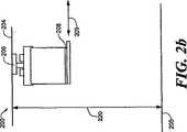
図2a−2bは、図1の自動材料搬送システムに使用されるオフセット ゼロ設置面積収納の第1の態様の分解組立図であり、オフセット ゼロ設置面積収納は移動棚の単一列からなる;
図3a−3bは、図2のオフセット ゼロ設置面積収納の第1の態様の分解組立図であり、オフセット ゼロ設置面積収納は多重の移動棚からなる;
図4a−4bは、図1の自動材料搬送システムに使用されるオフセット ゼロ設置面積収納の第2の態様の分解組立図であり、オフセット ゼロ設置面積は固定棚の単一列と移動ステージ上の高架ホイスト機構からなる;
図5は、WIP収納ユニットに接続して使用される図4の高架ホイスト機構の分解組立図である;
図6は、WIP部品コンベアシステムに接続して使用される図4の高架ホイスト機構の分解組立図である;
図7は、図4の高架ホイスト機構の代替態様の透視図である;
図8は、固定棚配列に接続して使用される図7の高架ホイスト機構の透視図である;
図9は、図7の高架ホイスト機構のような多重高架ホイスト機構の透視図であり、高架ホイスト機構は同じ軌道を移動し、そして固定棚の配列に接続して使用される;
図10は、図7の高架ホイスト機構のような多重高架ホイスト機構の透視図であり、高架ホイスト機構は各軌道を移動し、そして固定棚の背中併せの配列に接続して使用される;
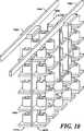
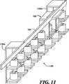
図11は、オフセット 設置面積ゼロ収納の第3の態様の透視図であり、図7の高架ホイスト機構が固定棚の多重配列に接続して使用される;
図12a−12bは、図1の自動材料搬送システムを作動させる説明のフロー説明図である;
図13は、図1の自動材料搬送システムを制御する方法のフロー説明図である;
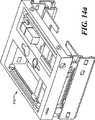
図14a−14bは、図4a−4bの移動ステージの透視図である。Other features, functions, and aspects of the invention will become apparent from the following detailed description of the invention.
BRIEF DESCRIPTION OF THE DRAWINGS The drawings, together with the following description, will be more fully understood in accordance with the following detailed description of the invention:
FIG. 1 is an exploded view of an IC chip manufacturing environment including an automated material handling system according to the present invention;
2a-2b are exploded views of a first aspect of offset zero footprint storage used in the automated material handling system of FIG. 1, wherein the offset zero footprint storage consists of a single row of moving shelves;
3a-3b are exploded views of the first aspect of offset zero footprint storage of FIG. 2, wherein the offset zero footprint storage comprises multiple moving shelves;
4a-4b are exploded views of a second aspect of offset zero footprint storage used in the automated material handling system of FIG. 1, where the offset zero footprint is a single row of fixed shelves and an elevated overhead on the moving stage. Consisting of a hoist mechanism;
FIG. 5 is an exploded view of the elevated hoist mechanism of FIG. 4 used in connection with a WIP storage unit;
6 is an exploded view of the elevated hoist mechanism of FIG. 4 used inconnection with a WIP partsconveyor system;
7 is a perspective view of an alternative embodiment of the elevated hoist mechanism of FIG. 4;
FIG. 8 is a perspective view of the elevated hoist mechanism of FIG. 7 used in connection with a fixed shelf arrangement;
FIG. 9 is a perspective view of a multiple elevated hoist mechanism, such as the elevated hoist mechanism of FIG. 7, which travels on the same track and is used in connection with an array of fixed shelves;
FIG. 10 is a perspective view of a multiple elevated hoist mechanism, such as the elevated hoist mechanism of FIG. 7, which is used in conjunction with a back-to-back arrangement of fixed shelves that travels each track;
FIG. 11 is a perspective view of a third mode of zero offset footprint storage with the elevated hoist mechanism of FIG. 7 used in connection with multiple arrays of fixed shelves;
12a-12b are explanatory flow diagrams illustrating the operation of the automatic material handling system of FIG. 1;
FIG. 13 is a flow diagram of a method forcontrolling the automatic material handling system of FIG. 1;
14a-14b are perspective views of the moving stage of FIGS. 4a-4b.
発明の詳細な説明
2002年10月11日に出願されたアメリカ仮特許出願番号 第60/417993号、名称 移動棚または移動ホイスト プラットホームを使用するオフセット ゼロ設置面積の収納(ZFS)は、この出願に参照として組み込まれる。DETAILED DESCRIPTION OF THE INVENTION US Provisional Patent Application No. 60 / 417,993, filed Oct. 11, 2002, Name Offset Zero Space Storage (ZFS) using a moving shelf or moving hoist platform is incorporated into this application. Incorporated as a reference.
改良された自動材料搬送システムはここに公開され、懸架軌道に支持される高架ホイスト機構が軌道側に位置する収納容器から仕掛品(WIP)部品を入手するのを可能とする。ここに公開される自動材料搬送システムは空間の使用をより効率良くし、一方で処理量を増やし、信頼性を高め、そしてコストを下げる。An improved automated material handling system is disclosed herein, which allows an elevated hoist mechanism supported on a suspended track to obtain WIP parts from a storage container located on the trackside . The automated material delivery system disclosed here makes space use more efficient while increasing throughput, increasing reliability, and lowering costs.
図1は、本発明に従う自動材料搬送システム(AMHS)100を含む製品製造環境101の態様を図で説明する。図の態様において、AMHS 100は自動的にWIP部品を収納し、それらを製品製造環境101内の種々のワークステーションおよび/または加工機械、たとえばそれぞれ投入/送出ポート 118−119を有する加工機械 114−115の間に搬送する構造となっている。FIG. 1 graphically illustrates aspects of a
AMHS 100は200mmまたは300mmFAB工場のような集積回路(IC)チップの製造のための清浄な環境または他の適当な製品製造環境で使用されることに注意されたい。図1で示されるように、ICチップ製造環境は天井104と床105を含み、それは典型的には電気非伝導性材料で覆われ、そして特定の耐荷重と耐震性を有する。さらに、加工機114−115はICチップを製造するための多くの加工工程を経由するように構成されている。たとえば、天井104は床105から約3.5mの距離120で隔てられ、加工機114−115は少なくとも約1.9mの距離126で離れるように隔てられ、そして投入/送出ポート118−119の頂部は床105から約0.9mの距離124で離れている。Note that
図の態様では、AMHS100は、それぞれ軌道106a−106bに可動的に連結した高架ホイスト搬送手段102a−102bを含み、二つとも天井104から懸架されている。高架ホイスト搬送手段102a−102bはそれぞれの高架ホイストを軌道106a−106bに沿って移動する構造であり、そしてWIP部品、すなわち、半導体ウエハーを収納するように設計された前開き一体化ポッド(FOUP)のような搬送具に到達する。図1に示すように、FOUP 108a−108bは棚 110a−110bのような収納ビンにそれぞれ収納される。さらに、懸架軌道106a−106bは棚 110a−110bの側を通過するルートをそれぞれ画定し、それにより高架ホイスト搬送手段 102a−102bがそれぞれの棚110a−110bからFOUP 108a−108bに直接、到達することを可能となる。たとえば、高架ホイスト搬送手段 102a−102bは床105の上約2.6mの距離122でもって配置され得る。In the illustrated embodiment,
特に棚110aは受動的または固定棚であり、それは懸架軌道106aの側で実質的に平行な列をなして配置される多くの固定棚の一つであり得る。固定棚の一つまたはそれ以上の列は軌道106aの一方の側または両側に配置され得ると理解されたい。図の態様では、固定棚110aからFOUP 108aに到達するには高架ホイスト搬送手段102aは懸架軌道106aに沿って棚110aの側の位置にまで移動する。次いで、高架ホイスト搬送手段102aに含まれる移動ステージ112は高架ホイストを高架ホイスト搬送手段102a内の第1の位置から固定棚110aの実質的に真上の第2の位置へ、矢印109aの示す方向へ横に動かす。高架ホイストはその後、作動してFOUP 108aを棚110aから直接、取り上げ、ICチップ製造床のワークステーションまたは加工機へ次ぎに搬送する。高架ホイストは代りに、棚110aに一つまたは一つ以上のFOUPを載置し得ることを理解されたい。移動ステージ112は高架ホイストがFOUPを高架ホイスト搬送手段102aからまたはそのいずれかの側へ取り上げるまたは載置することを可能にするように構成され得ることにも注意されたい。Especially the shelf 110a is a passive or solidTeitana, it may be one of a number of fixed shelves are arranged in substantially parallel rows onthe side of the suspended
好ましい態様では、固定棚110aは高架ホイスト搬送手段102aと実質的に同じ高さであり得る。この態様では、高架ホイスト搬送手段102aは、開口が形成されたカウル103aを含み、それを通して移動ステージ112が搬送手段から固定棚110aの上の位置へ移動するのを可能とする。棚110aからFOUP108aを取り上げた後に、移動ステージ112は高架ホイスト搬送手段102a内の元の位置へ戻されるとともに、FOUP108aはカウル103aの開口を通過する。 In a preferred embodiment, the fixed shelf 110a can be substantially the same height as the elevated hoist transport means 102a. In this aspect, the elevated hoist transport means 102a includes a cowl 103a having an opening formed therein, through which the moving stage 112 can move from the transport means to a position above the fixed shelf 110a. After picking up the FOUP 108a from the shelf 110a, the moving stage 112 is returned to the original position in the elevated hoist transfer means 102a, and the FOUP 108a passes through the opening of the cowl 103a.
棚110aは固定棚からなる一方、棚110bは移動棚である。固定棚110aと同様、移動棚110bは、懸架軌道106bの側で実質的に平行な列をなして配置される多くの移動棚の一つであり得る。さらに、移動棚の一つまたはそれ以上の列が軌道106bのいずれかの側または両側に配置され得る。図示の態様では、移動棚110b上のFOUP108bに到達するには高架ホイスト搬送手段102bは懸架軌道106bに沿って棚110bの側の位置にまで移動する。次いで、棚110bは軌道106bの脇の第1の位置から高架ホイスト搬送手段102b内の高架ホイストの真下の第2の位置へ横へ移動し、それは矢印109bで示される方向である。たとえば、移動棚110bには、軌道106bの脇の第1の位置と軌道と高架ホイストの下の第2の位置の間を空気力ステップモータまたはサーボモータ駆動の軸に沿って、棚110bを動かす機構が備えられ得る。高架ホイストは、その後作動してFOUP108bを直接に棚110bから取り上げて、ICチップ製造床上のワークステーションまたは加工機械へ次ぎに搬送する。高架ホイストは、代りに一つまたはそれ以上のFOUPを棚110bへ載置し得ることを理解されたい。The shelf 110a is a fixed shelf, while the shelf 110b is a movable shelf. Similar to the fixed shelf 110a, the moving shelf 110b can be one of many moving shelves arranged in a substantially parallel row on the side of the
固定棚110aと同様に、移動棚110bは高架ホイスト搬送手段102bと実質的に同じ床105上の高さであり得る。さらに、高架ホイスト搬送手段102bは開口が形成されたカウル103bを含み、該開口を通してFOUPを保持する移動棚110bが搬送手段102b内の高架ホイスト下の位置へ移動することを可能とする。FOUP108bが一旦高架ホイストで保持されると、棚110bは懸架軌道106b側の元の位置へ戻る。Similar to the fixed shelf 110a, the movable shelf 110b may be substantially the same height above the
ここに記載される自動材料搬送システムは、コンピュータ化された管理下に動作するということは認識されるべきである。たとえば、AMHS100はメモリから指令をする一つまたはそれ以上のプロセッサを含むコンピュータシステムからなる。ここに記載される操作を実行される命令は、演算システムの部分とみなせるプログラムコードとして記録された命令、アプリケーションの部分としてみなせるプログラムコードとして記録された命令、または演算システムとアプリケーションとの間に割り当てられたプログラムコードとして記録された命令からなることができる。さらに、メモリはランダムアクセスメモリ(RAM)、RAMと読取専用メモリ(ROM)との組合せ、または他の適当なプログラム記憶装置からなる。It should be appreciated that the automated material handling system described herein operates under computerized control. For example,
図2a−2bは自動材料搬送システム(AMHS)200を図解し、図1のICチップ製造環境101において使用され得る。図の態様では、AMHS200は懸架軌道206、および軌道206上を移動する構造の高架ホイスト搬送手段202を含む。高架ホイスト搬送手段202は、FOUP208を移動棚210からまたはそれへ取り上げるまたは載置させる様に構成されている。たとえば、高架ホイスト搬送手段202は天井204の下約0.9mの距離221で延びており、そして移動棚210は、床205の上約2.6mの距離222で配置され得る。それゆえ、天井204は、床205の上、約3.5mの距離220となり得る。2a-2b illustrate an automated material handling system (AMHS) 200 that may be used in the IC
好ましい態様では、移動棚210はICチップ製造設備の床205上に懸架される。たとえば、移動棚210は、軌道206から、天井204からまたは他の適当な構造から懸架され得る。移動棚は棚210と同様軌道206のいずれかの側または両側に懸架され得るので、棚210bはFOUP208に対してオフセット ゼロ設置面積収納(ZFS)を与え、それによりICチップ製造環境により効率的な空間の使用をなさせしめる。 In a preferred embodiment, the moving
上述のように、高架ホイスト搬送手段202は、FOUP208を移動棚210から取り上げるかまたはそこへ載置する構成である。そのため、高架ホイスト搬送手段202は懸架軌道206に沿って棚210の側の位置にまで移動する。図2aに示すように、軌道206の側に配置される棚210は、高架ホイスト搬送手段202と実質的に同じ高さである。次ぎに、棚210は、矢印209の示す方向で、高架ホイスト搬送手段202内の高架ホイストの実質的に直下の位置まで横へ移動する(図2bを参照)。高架ホイスト搬送手段202は、ホイスト把持具(たとえば、図5のホイスト把持具426を参照)を含み、それはFOUP208を棚210から取り上げるかまたは棚210へ載置する構成となっている。FOUP208が、一旦ホイスト把持具で保持されると、高架ホイスト搬送手段202は、それをICチップ製造床のワークステーションや加工機械へ移動させ得る。As described above, the overhead hoist conveyance means 202 is configured to pick up the
図3a−3bは、自動材料搬送システム(AMHS)300を図解するもので、図1のICチップ製造環境101に使用され得る。AMHS200と同様(図2a−2bを参照)、AMHS300は懸架軌道306と軌道306上を移動する構造の高架ホイスト搬送手段302を含む。しかし、AMHS200に含まれる高架ホスト搬送手段202はFOUP208を単一の棚列に配置される移動棚へまたはそこから取り上げるまたは載置する一方で、高架ホイスト搬送手段302はFOUP308を各列の棚に配置される選択された移動棚310―311へまたはそこから取り上げるまたは載置する構造である。たとえば、高架ホイスト搬送手段302は天井304の下の約0.9mの距離323で延びており、棚310は高架ホイスト搬送手段302と実質的に同じ高さで配置され、そして棚311は棚310bの下約0.4mの距離323で、そして床305の上の約2.6mの距離322で配置され得る。それ故、天井304は床305から約3.9mの距離320であり得る。 3a-3b illustrate an automated material handling system (AMHS) 300 that may be used in the IC
移動棚310―311は、軌道306の構造から、天井304からまたは他の適当な構造から懸架され得るので、棚310−311はFOUP 308に対するオフセット ゼロ設置面積収納(ZFP)の多重化列またはレベルを与える。さらに、棚の各列は実質的に隣接する棚の列の真上又は真下にあり、それにより棚の多重列又は多重行を含む少なくとも一つの棚配列を形成する。棚配列の棚の頂部の列(棚310を含む)は、高架ホイスト搬送手段302と実質的に同じ高さであり得る。Since the moving shelf 310-311 can be suspended fromthe structure of the
図の態様では、高架ホイスト搬送手段302は、FOUP 308を、移動棚310−311へ又はそれから取り上げる又は載置するように構成されている。FOUP308を棚308から取り上げるには、高架ホイスト搬送手段302は懸架軌道306に沿って棚310の側の位置にまで移動する。次いで、棚310は横に動いて、矢印309の示す方向で、高架ホイスト搬送手段302内の高架ホイストの真下の位置まで移動する(図3bを参照)。高架ホイスト搬送手段202と同様、高架ホイスト搬送手段302はホイスト把持具(例えば、図5のホイスト把持具426を参照)を含み、それはFOUP 308を棚310から又はそこへ直接、取り上げるか又は載置するように構成される。FOUP 308が一旦棚310から取り上げられてホイスト把持具で保持されると、高架ホイスト搬送手段302は、ICチップ製造床上のワークステーションまたは加工機へそれを移動し得る。In the illustrated embodiment, the elevated hoist transport means 302 is configured to pick up or place the
棚310の下の列ではなく、棚310の同じ行で棚311からFOUPを取り上げるには、高架ホイスト搬送車302はそれ自身棚310の側に位置する。次いで、棚311は横に動いて、高架ホイスト搬送手段302の内の実質的に高架ホイストの真下の位置へ、矢印309が示す方向で移動する。高架ホイストは棚311へ向かって通常の方法で低下し、ホイスト把持具を使って棚311からFOUP 308を取り上げる。次ぎに、高架ホイストは上昇して、FOUP308は高架ホイスト搬送手段308内のホイスト把持具により保持され、その後、高架ホイストはICチップ製造床上のワークステーションまたは加工機へ該FOUPを移動し得る。最終的に棚311は棚配列の元の位置へ戻る。Rather than the bottom row of the
高架ホイスト搬送車302に含まれる高架ホイストは選択された移動棚(たとえば、棚310―311)上に収納されたWIP部品に到達でき、それは懸架軌道306上の同じ位置から棚の同じ行に配置される。このように、高架ホイスト搬送手段302は単一の軌道位置からWIP収納の一つまたはそれ以上のレベルへ到達し得る。Movable rack overhead hoist included in the overhead hoist
図4a−4bは、自動材料搬送システム(AMHS)400を図解し、それは図1のICチップ製造環境101で使用され得る。図の態様では、AMHS400は懸架軌道406と、軌道406上を移動するように構成される高架ホイスト搬送手段402を含む。高架ホイスト搬送車402は受動的または固定棚410から又はそこへFOUP408を取り上げる又は載置するように構成される。たとえば、高架ホイスト搬送手段402は、天井404の下約0.9mの距離421で延びており、固定棚410aは床405の上約2.6mの距離422で配置され得る。棚410は高架ホイスト搬送手段402と同じ床上高さであり得ることに注意されたい。よって、天井404は床405の上約3.5mの距離420であり得る。4a-4b illustrate an automated material handling system (AMHS) 400 that may be used in the IC
棚410と同様複数の固定棚は軌道406の側で実質的に平行に単一の列または多重の列をなして配置され得ることを理解されたい。さらに、一つまたはそれ以上の固定棚の列は軌道406のいずれかの側または両側に位置し得る。固定棚の多重列が軌道構造から、天井404からまたは他の適当な構造から軌道406の側に懸架され得るので、固定棚はFOUP408のためのオフセット ゼロ設置面積収納(ZFS)の多くのレベルを与える。It should be understood that a plurality of fixed shelves, like the
図の態様では、高架ホイスト搬送手段402に含まれる高架ホイストは移動ステージ412上に装着されて、搬送手段402の側で選択された固定棚の実質的に真上の位置へホイストを移動する構成となっている。図14aは、引っ込んだ構造の移動ステージ412を図示し、図14bは、横に延長された構造の移動ステージ412を図解する。棚410からFOUP408を取り上げるには(図4a−4bを参照)、高架ホイスト搬送手段402は、懸架軌道406に沿って棚410の側の位置へ移動する。次ぎに、移動ステージ412は、矢印409の示す方向に、棚410の上の位置へ横に移動する(図4aを参照)。ホイスト把持具426(図5を参照)は、その後、作動して直接、棚410へ又はそれからFOUP408を取り上げる又は載置する。一旦、FOUP408が棚410から取り上げられて、ホイスト把持具426で把持されると、移動ステージ412は高架ホイスト搬送手段402内の元の位置へ戻る。移動ステージ412は搬送手段402内の元に位置へ戻る際には、FOUP408はカウル開口403を通過して搬送手段402へ移動することに注意されたい(図4bを参照)。高架ホイスト搬送手段402は、その後、ICチップ製造床上のワークステーション又は加工機へFOUP408を搬送する。In the embodiment shown, the configuration overhead hoist included in the overhead hoist
高架ホイスト搬送手段402に含まれる高架ホイストは選択された固定棚(たとえば、棚410a)上に配置されるWIP部品に到達でき、それは懸架軌道406上の同じ位置から棚の同じ行に配置される。例えば、棚410の下の列ではないが、棚410と同じ行の固定棚に配置されるFOUPに到達するには、高架ホイストは通常の方法で下段の棚の側の適当なレベルまで低下し、そして移動ステージ412は横に移動して、ホイスト把持具426がFOUPを棚から又はそこへ取り上げる又は載置することを可能とする。このようにして、高架ホイスト搬送手段402は単一の軌道位置からWIP収納の一つ又はそれ以上のレベルに到達し得る。The elevated hoist included in the elevated hoist transport means 402 can reach a WIP component located on a selected fixed shelf (eg, shelf 410a), which is located in the same row of the shelf from the same location on the
図5は、AMHS 400の図解応用を図示し(図4a−4bもまた参照)、そこではAMHS400は、WIP収納ユニット500(“ストッカー”)と共に使用される。図の態様では、ストッカー500はストッカー ハウジング内に配置される棚510のような複数の収納ビンを含む。ストッカー500内の収納ビンは中央軸を中心として回転し、高架ホイスト搬送手段402により取り出されるのが可能となる収納ユニット場所へ配置される。棚510からFOUP 508を取り上げるために、高架ホイスト搬送手段402は懸架軌道406に沿って移動し棚510の側の位置まで移動する。次いで、移動ステージ412は横に移動して、矢印409の示す方向で、棚510の実質的に真上の位置へ動く。ホイスト把持具426は、その後、作動してFOUP 508を直接、棚510から取り上げて、FOUP508をストッカー500から抜き取る。ホイスト把持具426は、代りに、ストッカー500内の棚510へFOUPを載置するのに使用され得ることを理解されたい。一旦、FOUP 508が棚510から取り上げられて、ホイスト把持具426により保持されると、移動ステージ412は高架ホイスト搬送手段402内の元の位置へ戻り、その後、高架ホイスト搬送手段402はFOUP408をICチップ製造床上のワークステーション又は加工機へ搬送する。FIG. 5 illustrates an illustrative application of AMHS 400 (see also FIGS. 4a-4b), where
図5の高架ホイストは代りに、ストッカー500の外の棚から又はそれへFOUPを取り上げる又は載置に注意されたい。たとえば、ストッカー500は、一つ又はそれ以上の移動棚を含むことができ、各棚は横に動いてストッカー500内の第1の位置からストッカー外の第2の位置へ移動し、高架ホイストがFOUPに到達するのを可能とする構造である。一旦、FOUPが棚から取り上げられてホイスト把持具426で保持されると、棚はストッカー500内の元の位置へ戻る。図5の高架ホイストを使用してFOUPに直接ストッカー500から到達すると、従来のI/O機構、例えば、投入/送出ポート118−119(図1を参照)が不要となり、それによりシステムのコストが低減できる。 Note that the elevated hoist of FIG. 5 instead takes up or places the FOUP from or to the shelf outside the
図6は、AMHS 400の図解応用を図示しており(また図4a−bも参照)、AMHS400は、高架WIPコンベヤ610と共に使用されている。図の態様では、移動ステージ412に設置された高架ホイストはFOUP 608を直接WIPコンベヤ610から又はそれへ取り上げる又は載置するのに使用され、レール606に沿って移動する構造となっている。レール606は図6の図面の面に垂直な方向に延びていることを理解されたい。高架ホイストは、FOUP 608を、レール敷設のコンベヤ610から取り上げ、そしてFOUP 608を例えば加工ツールロードポート635へ載置する、そしてその反対にもまた使用され得る。たとえば、高架ホイスト搬送手段402はレール敷設のコンベヤ610の上約0.35mの距離624で配置され得る。さらに、高架レール606はIC製造設備の床605の上約2.6mの距離626であり得る。FIG. 6 illustrates an illustrative application of AMHS 400 (see also FIGS. 4 a-b), where
懸架軌道、たとえば軌道406上を移動する高架ホイスト搬送手段は隣接ワークステーションと加工機械間のFOUPの移動には通常“ホップ ツー ホップ(hop to hop)”移動として利用され得る。反対に、レール敷設のコンベヤ610は、ICチップ製造床上の実質的にかなりの距離を離れて位置するワークステーションと加工機械の間をFOUPを搬送する急ぎの搬送とするのに利用され得る。ICチップ製造設備を横切り実質的にかなりの距離でもってFOUPを搬送するのにレール敷設のコンベヤを用いることにより、搬送システムの輻輳は有意に低減され得る。Suspended track, for example, the overhead hoist transport vehicle moving on the
上述のように、移動ステージ412上に装着された高架ホイストはレール敷設のコンベヤ610から又はそれへFOUP 608を取り上げる又は載置するのに利用され得る。このために、高架ホイスト搬送手段402とレール敷設のコンベヤ610は移動してそれに配置されるFOUP 608と共に搬送手段402はコンベヤ610の側に位置する。次いで、移動ステージ412は横に動いて、矢印409の示す方向でコンベヤ610の実質的に直接表面上にFOUP608を配置する。高架ホイストは、その後、矢印628の示す方向でコンベヤ610に向かって従来の方法で低下する。次ぎに、高架ホイストは、運転されてFOUP 608をコンベヤ610へ載置し、コンベア610はICチップ製造床を横切ってFOUP 608を次いで搬送する。As described above, the overhead hoistmounted on the moving
図7は、図4a−4bのAMHS 400の代りの態様700を図解したものである。AMHS 400と同様、AMHS 700は受動的または固定棚から又はそこへFOUPを取り上げるまたは載置するように構成されている。図の態様では、AMHS 700は懸架軌道706と軌道706に支持された高架ホイスト搬送手段702を含む。図7に示される様に、高架ホイスト搬送手段702は近接端744、末端746および近接端744と末端746間を結合する懸架要素748を含む。高架ホイスト搬送手段702はさらに、末端746に設置されたホイスト把持具726と近接端744に可動的に接続し、そして搬送手段702が軌道706上を移動するのを可能とするように構成される搬送部材742を含む。FIG. 7 illustrates an
特に、近接端744は矢印709の示す方向で軌道706に実質的に垂直の方向で搬送部材742に相対的に横に動く様に構成される。例えば、近接端744はY−表、空気機構、ステッパーサーボ機構又は相対的に長い横の偏倚を与える他の適当な機構として動き得る。さらに、末端746は矢印728が示す方向で垂直の方向に移動する構成となっている。たとえば、末端746は懸架要素748の端と結合し得て、該要素は入れ子式に縮んで末端746が所望の垂直方向へ移動するのを可能とする構造であり得る。それ故、近接端744と懸架要素748の組合せは、ホイスト把持具726を収納する末端746が、矢印の方向709と728で特定されるように、自由度2(2−degrees−of−freedom)で移動するのを可能とする。In particular, the
図8は、受動的又は固定棚の配列800と共に使用される図7のAMHS 700を図解する。図の態様では、高架ホイスト搬送手段702はFOUP、たとえばFOUP 808を配列800内の選択された棚から又はそれへ取り上げるまたは載置するように構成されており、該配列は棚810のように固定棚の多重列または多重行を含む。図8に示すように、棚配列800は、懸架軌道706の側で実質的に平行で配置される。さらに、各棚は、床に固定され得る垂直の支持部材760に対して単一の縁に沿って設けられ、棚の隣接する行は、間隔が開いていて、それぞれの懸架要素748が隣接する行の間隔に嵌まり込むことを可能とする。この構造では、FOUP 808は、望むならば、手動で到達可能にオープンされていることに注意されたい。FIG. 8 illustrates the
たとえば、棚810からFOUP808を取り上げるには、高架ホイスト搬送手段702は懸架軌道706に沿って移動して棚810を含む行の側の位置まで移動する。次いで、ホイスト把持具を含む末端746は矢印728が示す方向で、下向きに動き、FOUP808を保持する棚810の側の位置まで動く。近接端744は、その後、横に動き、矢印709の示す方向で、軌道706の側で棚810の実質的に真上のホイスト把持具726の位置まで移動する。近接端744はその横に動いて、各懸架要素748は棚の行の各側の空間に収容されることに注意されたい。For example, in order to pick up the
一旦FOUP 808が、ホイスト把持具726により棚810から取り上げられると、近接端744は、軌道706の下の元の位置へ戻り、それによりホイスト把持具726にFOUP 808を保持させて、末端746は軌道706の方へ上って戻ることを可能とする。搬送部材742は、その後、ICチップ製造床上のワークステーションまたは加工機までFOUP 808を移動させる。高架ホイスト搬送手段702は懸架軌道706上の同じ位置から棚の同じ行に配置され、選択された棚に収納されるWIP部品に到達し得ることを理解されたい。このように、高架ホイスト搬送手段702は、単一の軌道位置からWIP収納の一つまたはそれ以上のレベルに到達し得る。Once the
図9は、棚配列800と共に使用される複数の自動材料搬送システム(AMHS)700a−700bを図解する。各AMHS 700a−700bは図7のAMHS 700に似ていることを理解されたい。図の態様では、AMHS 700a−700bは単一の軌道706上を移動して棚配列800に収納されるFOUP 808に同時の到達を可能となるように構成され、それにより高いシステム処理量を確保するものである。 FIG. 9 illustrates a plurality of automated material handling systems (AMHS) 700a-700b used with the
図10は、増大する収納密度のために背中合わせ配置の棚の800a−800bの二つの配列と共に使用されるAMHS 700a−700bを図解する。図10に示される様に、棚配列800a−800bの各々は床に固定された垂直支持部材1060の単一の端に沿って設置される。棚配列800a−800bの各棚は棚配列800と似ており(図8参照)、そこでは棚の隣接行が間隔を置いて配置されて、各懸架要素748が隣接行の間に嵌まり込むことを可能とする。図の態様では、AMHS 700a−700bは懸架軌道706a−706b上をそれぞれ移動して棚配列800a−800bに収納されるFOUPの同時到達を可能とする構造であり、それにより高いシステムの処理量が確保される。図8−10のシステムの構造はFOUPに到達するにロボット(従来の材料搬送システムと同様な)を必要としないので、床空間の必要性とシステムのコストは減少し、一方でシステムの信頼性は増大する。FIG. 10 illustrates
図11は、固定棚の配列1100と共に使用される図7のAMHS 700を図解する。棚配列800と同様に(図8を参照)、棚配列1100は、懸架軌道706の側で実質的に平行に配置される。さらに、各棚は一つまたはそれ以上の垂直支持部材1160a−1160bの単一の端に設けられ、そして棚の隣接行は間隔が開いて、各懸架要素748が隣接行間の間隔に嵌まり込むことを可能としている。しかし、棚配列800が床に固定される一方で、棚配列1100は支持部材1160a−1160bにより軌道706の構造から懸架される。棚配列1100は代わりに、天井または他の適当な構造から懸架され得ることを理解されたい。その結果、棚配列1100は、そこに収納されるFOUPのオフセット ゼロ設置面積収納(ZFS)の多重の列またはレベルを与える。FIG. 11 illustrates the
ここに開示の自動材料搬送システムを操作する第1の方法は図12aを参照して説明される。ステップ1202に図解されるように、高架ホイスト搬送(OHT)手段は懸架軌道に沿って移動して棚配列の選択された移動棚の側の位置まで動く。棚はそれに配置される少なくとも一つのFOUPを有する。次いで、棚は、ステップ1204に図解されるように、OHT車に含まれる高架ホイストの下の位置まで移動する。高架ホイストは、ステップ1208に図解されるように、その後作動して、棚からFOUPを取り上げる。次に、ステップ1208に図解されるように、棚は移動して、棚配列の元の位置まで戻る。最終的には、OHT搬送手段は、ステップ1210に図解されるように、製品製造床上のワークステーションまたは加工機までFOUPを搬送する。Afirst method of operating the automated material delivery system disclosed herein will be described with reference to FIG. 12a. As illustrated in
ここに開示される自動材料搬送システムを操作する第2の方法は、図12bを参照して説明される。ステップ1212に図解されるように、OHT搬送手段は懸架軌道に沿って棚配列の選択された固定棚の側の位置まで移動する。棚には少なくとも一つのFOUPが配置されている。ついで、それに設置される高架ホイストを有する移動ステージはステップ1214に図解されるように、棚の上の位置まで移動する。高架ホイストは、その後作動して、ステップ1216に図解のように、棚からFOUPを取り上げる。次ぎに、移動ステージは、ステップ1218に図解されるように、OHT搬送手段の元の位置まで戻る。OHT搬送手段は、その後、ステップ1220に図解されるように、製品製造床上のワークステーションまたは加工機械までFOUPを移動させる。次ぎに、高架ホイストが作動して、ステップ1222に図解のように、FOUPを加工機械のI/Oポートへ載置し、それは移動ステージをI/Oポート上の位置へ動かし、FOUPをI/Oポートへ載置し、そして移動ステージをOHT搬送手段内の元の位置へ動かす。高架ホイストは、次いで作動して、ステップ1224に図解されるように、加工機械のI/OポートからFOUPを取り上げる。次ぎに、OHT搬送手段は、ステップ1226に図解のように、レール敷設のコンベヤの側の位置まで移動する。移動ステージはその後、ステップ1228に図解のように、動いて、レール敷設のコンベヤ上にFOUPを載置する。次に、FOUPを保持する高架ホイストは、ステップ1230に図解のように、コンベヤに向って低下し、そして高架ホイストは、ステップ1232に図解のように、FOUPをコンベヤに載置する。移動ステージがOHT搬送手段内の元の位置へ戻った後に、レール敷設のコンベヤはステップ1234に図解のように、FOUPを製品製造床を横切り長距離にわたって搬送する。A second method of operating the automated material delivery system disclosed herein is described with reference to FIG. 12b. As illustrated in
ここに開示の自動材料搬送システムの制御方法は、図13を参照して説明される。収納場所は、あふれたFOUPを、個々のツールから、一群のツールからまたはベイ(bay)から搬送するように構成される。収納ユニットは、一つまたはそれ以上の収納場所である。システムの制御器は宛先ツール近辺のFOUPを収納しそして収納場所ユニット内の収納を搬送して、ユニット内の他のFOUPの素早い回復と保管を最適化する。ステップ1302に図解のように、AMHS制御器はFOUPをともなう高架ホイスト搬送手段を加工ツールへ向けさせる。次いで、ステップ1304が示すように、FOUPを受け入れるのに加工ツールが利用できない。ステップ1306に図解のように、その後、加工ツールに連動する収納ユニットがFOUPを保管可能か否かが判断される。もしも肯定のときは、ステップ1310に図解のように、AMHS制御器はFOUPを加工ツールの収納ユニットへ割り当てる。そうでないときは、ステップ1308に図解のように、加工ツールの群に連動する収納ユニットがFOUPを保管可能かを判断する。もしも肯定ならば、AMHS制御器はステップ1312に図解のように、FOUPを加工ツールの群の収納ユニットへ割り当てる。そうでない場合は、AMHS制御器は、ステップ1314に図解のように、FOUPを半導体ベイの収納ユニットへ割り当てる。ステップ1310、1312および1314のそれぞれを遂行することにより、AMHS制御器は、ステップ1316に図解のように、AMHS制御器のコンピューティング機器に内蔵されるアルゴリズムを実行することにより、AMHS内にFOUPを配置し、その回復を効率良く予定付けることが可能となる。Thecontrol method of the automatic material conveyance system disclosed herein will be described with reference to FIG. The storagelocation is configured tocarry overflow FOUPs fromindividual tools, from a group of tools, or from abay . A storage unit is one or more storagelocations . Controller systemconveys the accommodating FOUP near the destination tooland accommodatedin the accommodatinglocation unit tooptimize storage and other FOUP of rapid recovery in the unit. As illustrated in
上で図解により態様を説明したので、他の代わりの態様または変形が可能となる。たとえば、自動材料搬送システムは、ICチップ製造環境において前開き一体型ポッド(FOUP)のような搬送具を近づけるため高架ホイストを移動させる構成の高架ホイスト搬送手段からなることを説明した。しかし、上述の自動材料搬送システムは、物品があちらこちらに収納され移動される適当な環境に使用され得ることを理解されたい。たとえば、ここに説明した自動材料搬送システムは、自動車製造設備に使用され得るし、また当該システムにより収納され移動されるWIP部品は自動車の部品からなり得る。Having described aspects by way of illustration above, other alternative aspects or variations are possible. For example, automated material handling system hasbeen described that consist of overhead hoist transport vehicle configurations for moving the elevated hostLee striketo approximate conveyance member such as a front opening integral pods (FOUP) in the IC chip manufacturing environment. However, it should be understood that the automatic material delivery system described above may be used inany suitable environment where articles are stored andmoved from place to place. For example, the automated material handling system described herein can be used in an automobile manufacturing facility, and the WIP parts housed and moved by the system can consist of automobile parts.
単一の軌道位置から高架ホイスト搬送手段により棚の一つまたはそれ以上のレベルに到達するという上述のシステムと方法を、当業者により、ここに開示の発明の基本から離れることなしに更に変更または変形され得ることを理解されたい。それ故、本発明は、付属の請求項の範囲と精神により制限されない限り、限定的に解釈されない。 The above-described system and method of reaching one or more levels of shelves by elevated hoist transport means from a single track position can be further modified or changed by those skilled in the art without departing from the basis of the disclosed invention. It should be understood that variations can be made. Accordingly, the invention is not to be construed as limiting unless it is limited by the scope and spirit of the appended claims.
Claims (28)
Translated fromJapanese懸架軌道、高架ホイストおよび高架ホイスト搬送手段を具備する少なくとも一つの高架ホイスト搬送サブシステムであって、前記高架ホイスト搬送手段は移動ステージを備え、この移動ステージに前記高架ホイストが取り付けられている前記高架ホイスト搬送サブシステムと、
少なくとも一つの材料収納棚を含む材料収納部であって、この材料収納部は、少なくとも一つの材料ユニットを収納すると共に前記懸架軌道の第1の側に固定配置されている前記材料収納部と、を有し、
前記高架ホイスト搬送手段は、前記高架ホイストを懸架軌道に沿って移動させると共に、前記高架ホイストが加工ツールロードポートの真上に来たとき前記高架ホイストを真下に降ろして前記材料ユニットを加工ツールロードポートに載置するか、又は、前記高架ホイストが加工ツールロードポートにある前記材料ユニットを真上に引き上げるようになっており、
前記高架ホイスト搬送手段は、前記高架ホイストを懸架軌道に沿って前記材料収納部に隣接する第1の位置に移動させるようになっていて、さらに、前記材料収納部が高架ホイストのレベルよりも低いレベルに配置されている場合には、高架ホイストを前記材料収納部の前記低いレベルまで低下させるものであり、
前記高架ホイストは、前記材料収納部の前記低いレベルにまで低下される間、前記高架ホイスト搬送手段から降りるようになっており、
前記移動ステージは、前記懸架軌道に対して横に延びる構造を持ち、材料収納部所において材料ユニットを取り上げて前記第1の位置に移動させるか、又は、材料ユニットを前記第1の位置から材料収納部へ移動させて載置するようになっている自動材料搬送システム。An automatic material handling system,
At least one elevated hoist conveying subsystem comprising a suspended track, an elevated hoist and an elevated hoist conveying means,wherein the elevated hoist conveying means includes a moving stage, and the elevated hoistis attached to themoving stage.A hoist transport subsystem ;
A material storageunit including at least one material storage bin,the material accommodatingportion,with the material accommodating portion which isfixedly arranged on a first side ofboth the suspended track when storing at least one materialunit, Have
The elevated hoist conveying means moves the elevated hoist along a suspension track, and when the elevated hoist comes directly above the machining tool load port, lowers the elevated hoist directly below the machining tool load. Placed on the port, or the elevated hoist is adapted to pull the material unit at the machining tool load port straight up,
The elevated hoist conveying means is adapted tomove the elevated hoistalong a suspension track to a first position adjacent to the material accommodatingportion ,and the material accommodatingportion is lower than the level of the elevated hoist. If RuTei arranged level, which reduces the overhead hoist tothe lower level ofthe materialstorage,
The overhead hoist is while being lowered tothe low level ofthe material accommodatingportion and adapted to get off fromthe overhead hoist transport vehicle,
The moving stagehas a structure extending transversely tothe suspended trackor pick up the material unit in the material storage plant is moved to the first position, or material material unit from the first position An automatic material transfer systemthat is moved to the storage and placed .
懸架軌道、高架ホイストおよび高架ホイスト搬送手段を具備する少なくとも一つの高架ホイスト搬送サブシステムであって、前記高架ホイスト搬送手段は移動ステージを備え、この移動ステージに前記高架ホイスト及びホイスト把持部が取り付けられており、この高架ホイスト搬送手段が、高架ホイストを懸架軌道に沿って複数の位置へ搬送し、高架ホイストを複数のレベルへ上昇または低下させる前記高架ホイスト搬送サブシステムと、
少なくとも一つの材料ユニットを収納する少なくとも一つの材料収納部であって、この少なくとも一つの材料収納部は懸架軌道の第1の側の所定のレベルに固定配置されている前記材料収納部と、を有し、
前記高架ホイスト搬送手段は、前記高架ホイストを懸架軌道に沿って移動させると共に、前記高架ホイストが加工ツールロードポートの真上に来たとき前記高架ホイストを真下に降ろして前記材料ユニットを加工ツールロードポートに載置するか、又は、前記高架ホイストが加工ツールロードポートにある前記材料ユニットを真上に引き上げるようになっており、
前記高架ホイスト搬送手段は、移動ステージ、高架ホイスト、ホイスト把持具を懸架軌道に沿って材料収納部に隣接する第1の位置へ搬送し、そしてホイスト把持具を材料収納部とほぼ同じレベルに位置させるために高架ホイストを低下または上昇させものであり、
移動ステージは、少なくともホイスト把持具が材料収納部とほぼ同じレベルに位置する間は、ホイスト把持具を高架ホイスト搬送手段に隣接する第1の位置から材料収納部の第2の位置に向かって横に延びることにより移動させるものであり、これにより、ホイスト把持具が少なくとも一つの材料ユニットを材料収納部において吊持するかまたは材料収納部へ載置することが可能となる自動材料搬送システム。An automated material handling system,
At least one elevated hoist conveying subsystem comprising a suspended track, an elevated hoist and an elevated hoist conveying means,wherein the elevated hoist conveying means comprises a moving stage, and the elevated hoist and hoist gripping portion are attached to the moving stage. and, the overhead hoist transport vehicleis, the overhead hoist along a suspended track and conveyed to a plurality of positions,and the overhead hoist transport subsystem increasing or decreasing the overhead hoist to a plurality oflevels,
At least one material storagesection for storing at least one material unit, wherein the at least one material storagesection is fixedly arranged at a predetermined level on the first side of thesuspension track; Have
The elevated hoist conveying means moves the elevated hoist along a suspension track, and when the elevated hoist comes directly above the machining tool load port, lowers the elevated hoist directly below the machining tool load. Placed on the port, or the elevated hoist is adapted to pull the material unit at the machining tool load port straight up,
The elevated hoist conveying means conveys the moving stage, the elevated hoist, and the hoist gripping tool along the suspension track to a firstposition adjacent to the material storageunit , and thehoist gripping tool is positioned atsubstantially the same level as the material storageunit. To lower or raise the overhead hoist to
The moving stage moves the hoist gripping tool from the first positionadjacent to the elevated hoist conveying means toward the second position of the material storage section at least while the hoist gripping tool is positioned atsubstantially the same level as the material storage section. It is intended to move by extending,thereby,automated material handling system is possible to hoist gripperis placed into ormaterial storage for hangingin the material accommodating portion at least one material unit.
Applications Claiming Priority (2)
| Application Number | Priority Date | Filing Date | Title |
|---|---|---|---|
| US41799302P | 2002-10-11 | 2002-10-11 | |
| PCT/US2003/032200WO2004034438A2 (en) | 2002-10-11 | 2003-10-09 | Access to one or more levels of material storage shelves by an overhead hoist transport vehicle from a single track position |
Publications (3)
| Publication Number | Publication Date |
|---|---|
| JP2006515256A JP2006515256A (en) | 2006-05-25 |
| JP2006515256A5 JP2006515256A5 (en) | 2006-12-07 |
| JP4626302B2true JP4626302B2 (en) | 2011-02-09 |
Family
ID=32094132
Family Applications (1)
| Application Number | Title | Priority Date | Filing Date |
|---|---|---|---|
| JP2004543686AExpired - LifetimeJP4626302B2 (en) | 2002-10-11 | 2003-10-09 | A method of reaching one or more levels of material storage shelves from a single track position by elevated hoist transport means |
Country Status (8)
| Country | Link |
|---|---|
| US (1) | US10957569B2 (en) |
| EP (2) | EP2615625B2 (en) |
| JP (1) | JP4626302B2 (en) |
| KR (10) | KR101446511B1 (en) |
| CN (1) | CN1849251B (en) |
| AU (1) | AU2003284051A1 (en) |
| TW (1) | TWI302902B (en) |
| WO (1) | WO2004034438A2 (en) |
Cited By (2)
| Publication number | Priority date | Publication date | Assignee | Title |
|---|---|---|---|---|
| US9620397B2 (en) | 2002-06-19 | 2017-04-11 | Murata Machinery Ltd. | Automated material handling system for semiconductor manufacturing based on a combination of vertical carousels and overhead hoists |
| US10957569B2 (en) | 2002-10-11 | 2021-03-23 | Murata Machinery Ltd. | Access to one or more levels of material storage shelves by an overhead hoist transport vehicle from a single track position |
Families Citing this family (69)
| Publication number | Priority date | Publication date | Assignee | Title |
|---|---|---|---|---|
| US20070092359A1 (en)* | 2002-10-11 | 2007-04-26 | Brooks Automation, Inc. | Access to one or more levels of material storage shelves by an overhead hoist transport vehicle from a single track position |
| JP4045451B2 (en)* | 2003-12-26 | 2008-02-13 | 村田機械株式会社 | Overhead traveling vehicle system |
| DE102004032659B4 (en)* | 2004-07-01 | 2008-10-30 | Atotech Deutschland Gmbh | Apparatus and method for the chemical or electrolytic treatment of material to be treated and the use of the device |
| JP4337683B2 (en)* | 2004-08-16 | 2009-09-30 | 村田機械株式会社 | Transport system |
| JP4221603B2 (en)* | 2005-03-31 | 2009-02-12 | 村田機械株式会社 | Overhead traveling vehicle system |
| JP4394027B2 (en)* | 2005-04-05 | 2010-01-06 | 村田機械株式会社 | Overhead traveling vehicle system |
| US7661919B2 (en) | 2005-09-28 | 2010-02-16 | Muratec Automation Co., Ltd. | Discontinuous conveyor system |
| US7780392B2 (en)* | 2005-10-27 | 2010-08-24 | Muratec Automation Co., Ltd. | Horizontal array stocker |
| US8272827B2 (en)* | 2005-11-07 | 2012-09-25 | Bufano Michael L | Reduced capacity carrier, transport, load port, buffer system |
| US20080107507A1 (en)* | 2005-11-07 | 2008-05-08 | Bufano Michael L | Reduced capacity carrier, transport, load port, buffer system |
| KR20080075164A (en)* | 2005-11-07 | 2008-08-14 | 브룩스 오토메이션 인코퍼레이티드 | Reduced capacity carriers, conveyers, load ports and buffer systems |
| US8267634B2 (en)* | 2005-11-07 | 2012-09-18 | Brooks Automation, Inc. | Reduced capacity carrier, transport, load port, buffer system |
| CN100435310C (en)* | 2005-12-19 | 2008-11-19 | 中芯国际集成电路制造(上海)有限公司 | Automatic material transport system for semiconductor production |
| JP2007191235A (en)* | 2006-01-17 | 2007-08-02 | Murata Mach Ltd | Overhead traveling vehicle system |
| JP5041207B2 (en)* | 2006-11-14 | 2012-10-03 | 株式会社ダイフク | Goods transport equipment |
| JP4849331B2 (en)* | 2006-11-14 | 2012-01-11 | 株式会社ダイフク | Goods transport equipment |
| JP4277287B2 (en)* | 2006-11-27 | 2009-06-10 | 村田機械株式会社 | Overhead traveling car |
| JP2008195471A (en)* | 2007-02-09 | 2008-08-28 | Daifuku Co Ltd | Article conveying facility |
| JP4389181B2 (en) | 2007-03-07 | 2009-12-24 | 株式会社ダイフク | Article processing equipment |
| JP4378655B2 (en)* | 2007-03-07 | 2009-12-09 | 株式会社ダイフク | Article processing equipment |
| JP4378656B2 (en)* | 2007-03-07 | 2009-12-09 | 株式会社ダイフク | Goods transport equipment |
| US20090067957A1 (en)* | 2007-09-06 | 2009-03-12 | Mitsuhiro Ando | Transport system with buffering |
| JP4543338B2 (en)* | 2007-11-13 | 2010-09-15 | 村田機械株式会社 | Overhead vehicle system and its buffer construction method |
| US7992734B2 (en)* | 2008-01-11 | 2011-08-09 | International Business Machines Corporation | Semiconductor automation buffer storage identification system and method |
| US9633881B2 (en)* | 2008-02-05 | 2017-04-25 | Brooks Automation, Inc. | Automatic handling buffer for bare stocker |
| US9048274B2 (en)* | 2008-12-08 | 2015-06-02 | Taiwan Semiconductor Manufacturing Co., Ltd. | Portable stocker and method of using same |
| KR100959505B1 (en)* | 2009-08-12 | 2010-05-27 | (주) 엠에스피 | Auto load buffer in wafer transfer system |
| JP5445015B2 (en)* | 2009-10-14 | 2014-03-19 | シンフォニアテクノロジー株式会社 | Carrier transfer promotion device |
| US8977387B2 (en)* | 2009-10-29 | 2015-03-10 | Taiwan Semiconductor Manufacturing Company, Ltd. | System and method for overhead cross-system transportation |
| JP5273118B2 (en)* | 2010-10-04 | 2013-08-28 | 村田機械株式会社 | Transport vehicle and transport system |
| SG189232A1 (en)* | 2010-11-04 | 2013-05-31 | Murata Machinery Ltd | Conveying system and conveying method |
| JP5750926B2 (en)* | 2011-02-15 | 2015-07-22 | 村田機械株式会社 | Ceiling transport vehicle |
| JP5472209B2 (en)* | 2011-05-31 | 2014-04-16 | 株式会社ダイフク | Goods transport equipment |
| US8888434B2 (en)* | 2011-09-05 | 2014-11-18 | Dynamic Micro System | Container storage add-on for bare workpiece stocker |
| KR20130098688A (en)* | 2012-02-28 | 2013-09-05 | 삼성전자주식회사 | Hoist apparatus and its hoist system |
| US9558978B2 (en)* | 2012-05-04 | 2017-01-31 | Kla-Tencor Corporation | Material handling with dedicated automated material handling system |
| PL2754357T4 (en)* | 2013-01-09 | 2019-04-30 | Hauni Maschinenbau Gmbh | Method for supply and removal of full and/or empty transport units from at least two production stations in the tobacco-processing industry according to requirements |
| US9852934B2 (en)* | 2014-02-14 | 2017-12-26 | Taiwan Semiconductor Manufacturing Company, Ltd. | Semiconductor wafer transportation |
| US10332770B2 (en) | 2014-09-24 | 2019-06-25 | Sandisk Technologies Llc | Wafer transfer system |
| JP6048686B2 (en)* | 2014-09-25 | 2016-12-21 | 村田機械株式会社 | Temporary storage device, transport system and temporary storage method |
| WO2016169694A1 (en)* | 2015-04-22 | 2016-10-27 | Integrated Dynamics Engineering Gmbh | Service cart |
| CN107922116B (en)* | 2015-08-14 | 2019-11-22 | 村田机械株式会社 | Transportation system |
| CN105173504A (en)* | 2015-09-29 | 2015-12-23 | 扬中中科维康智能科技有限公司 | Automatic storage robot system |
| CN105564442B (en)* | 2016-01-15 | 2018-03-02 | 彭红廷 | Kong Tie transportation systems and empty iron transportation resources |
| KR102326782B1 (en)* | 2016-06-28 | 2021-11-17 | 무라다기카이가부시끼가이샤 | Overhead manufacturing, processing and storage system |
| CN106743016B (en)* | 2016-12-29 | 2018-10-09 | 库控(上海)实业有限公司 | A kind of mechanization access warehouse |
| KR102037950B1 (en)* | 2017-08-17 | 2019-10-29 | 세메스 주식회사 | Wafer supply module and die bonding apparatus including the same |
| US11027944B2 (en)* | 2017-09-08 | 2021-06-08 | Otis Elevator Company | Climbing elevator transfer system and methods |
| US11515186B2 (en)* | 2017-11-02 | 2022-11-29 | Murata Machinery, Ltd. | Ceiling conveyance vehicle system and temporary storage method for articles in ceiling conveyance vehicle system |
| MY188417A (en) | 2017-11-14 | 2021-12-08 | Hai Robotics Co Ltd | Automated guided vehicle designed for warehouse |
| US12103771B2 (en) | 2017-11-14 | 2024-10-01 | Hai Robotics Co., Ltd. | Handling robot |
| US12006143B2 (en)* | 2017-11-14 | 2024-06-11 | Hai Robotics Co., Ltd. | Handling robot |
| US11465840B2 (en) | 2017-11-14 | 2022-10-11 | Hai Robotics Co., Ltd. | Handling robot |
| US11396424B2 (en) | 2017-11-14 | 2022-07-26 | Hai Robotics Co., Ltd. | Handling robot |
| US12330870B2 (en) | 2017-11-14 | 2025-06-17 | Hai Robotics Co., Ltd. | Handling robot |
| CN108423352A (en)* | 2017-12-16 | 2018-08-21 | 楚天科技股份有限公司 | Workshop hidden intelligence movement system |
| US11437258B2 (en) | 2018-08-30 | 2022-09-06 | Taiwan Semiconductor Manufacturing Co., Ltd. | Workpiece storage system, method of storing workpiece, and method of transferring workpiece using the same |
| JP6814412B2 (en)* | 2018-10-23 | 2021-01-20 | 村田機械株式会社 | Transport system |
| US11542135B2 (en) | 2019-02-01 | 2023-01-03 | Hai Robotics Co., Ltd. | Handling robot |
| US11597598B2 (en) | 2019-02-01 | 2023-03-07 | Hai Robotics Co., Ltd. | Handling robot |
| CN113573991B (en)* | 2019-03-22 | 2022-10-21 | 村田机械株式会社 | Carrier system |
| KR102242361B1 (en) | 2019-12-10 | 2021-04-20 | 제닉스주식회사 | Trasnporting system and controlling method of transporting system |
| KR102801222B1 (en) | 2020-11-10 | 2025-04-30 | 삼성전자주식회사 | Apparatus for storage of carrying material |
| CN114823442A (en)* | 2021-01-27 | 2022-07-29 | 中芯国际集成电路制造(北京)有限公司 | Automatic material handling system of semiconductor |
| KR102849280B1 (en) | 2021-08-10 | 2025-08-25 | 삼성전자주식회사 | Storage system including shelf moving module |
| CN113467199B (en)* | 2021-09-06 | 2021-11-12 | 宁波润华全芯微电子设备有限公司 | Device convenient to dismantle and capable of preventing wafer from being polluted by splashing liquid |
| CN118748976A (en)* | 2022-03-10 | 2024-10-08 | 海普电梯公司 | Dynamic traction drives for vertical transport systems |
| JPWO2023218757A1 (en)* | 2022-05-10 | 2023-11-16 | ||
| EP4432336B1 (en)* | 2023-02-23 | 2025-06-18 | Fabmatics GmbH | Shuttle storage and method for producing the same |
Family Cites Families (194)
| Publication number | Priority date | Publication date | Assignee | Title |
|---|---|---|---|---|
| US618318A (en)* | 1899-01-24 | Coin-case | ||
| US328408A (en) | 1885-10-13 | isbell | ||
| US343293A (en) | 1886-06-08 | bowen | ||
| US1352947A (en)* | 1917-10-29 | 1920-09-14 | Jonathan P B Fiske | Process for handling clay products |
| US2317689A (en) | 1941-04-21 | 1943-04-27 | Earl B Spencer | Underdrive for traveling cranes, monorails, and the like |
| US2827189A (en) | 1955-10-27 | 1958-03-18 | Robert N Sergeant | Lift truck attachment for handling drums |
| US3049247A (en) | 1956-04-10 | 1962-08-14 | Jerome H Lemelson | Automated storage |
| US3042227A (en) | 1958-09-26 | 1962-07-03 | Sea Land Service | Shipboard freight container transferring apparatus |
| US3119501A (en) | 1961-10-10 | 1964-01-28 | Jerome H Lemelson | Automatic warehousing system |
| US3422967A (en) | 1965-10-24 | 1969-01-21 | Peter A Aron | Automatic manipulator and positioning system |
| US3467264A (en) | 1966-07-19 | 1969-09-16 | Euclid Crane & Hoist Co The | Load transfer and storage mechanism |
| US3499554A (en)* | 1968-02-21 | 1970-03-10 | Commercial Affiliates | Stacker crane and warehouse system and method for stacking and storing rolls of material |
| JPS4831521B1 (en) | 1968-05-07 | 1973-09-29 | ||
| US3750804A (en)* | 1969-03-07 | 1973-08-07 | Triax Co | Load handling mechanism and automatic storage system |
| US3531002A (en)* | 1969-07-15 | 1970-09-29 | Triax Co | Automatic storage apparatus |
| US3583584A (en) | 1969-08-18 | 1971-06-08 | Mcneil Corp | Warehousing |
| US3701442A (en) | 1970-09-25 | 1972-10-31 | Mcneil Corp | Storage and retrieval apparatus |
| US3700121A (en) | 1971-02-22 | 1972-10-24 | Baker Perkins Inc | Rack loading and unloading apparatus |
| US3762531A (en)* | 1971-08-26 | 1973-10-02 | Eaton Corp | Load stacker |
| CH542137A (en) | 1972-04-19 | 1973-09-30 | Sperry Rand Corp | Device for locking and controlling the locking of containers for transport on carriers in an article storage system |
| US3770137A (en) | 1972-09-01 | 1973-11-06 | I Slutsky | Overhead transporter and reloader |
| US3968885A (en) | 1973-06-29 | 1976-07-13 | International Business Machines Corporation | Method and apparatus for handling workpieces |
| US4088232A (en)* | 1974-04-01 | 1978-05-09 | Clark Equipment Co. | Apparatus with storage cells disposed adjacent vertical shafts having covers and a lift means movable thereabove |
| US4190013A (en)* | 1977-03-22 | 1980-02-26 | Otis Roger W | Floating dry storage facility for small boats |
| US4398630A (en) | 1978-07-17 | 1983-08-16 | Brems John Henry | Workpiece vertical conveyor system |
| US4243147A (en) | 1979-03-12 | 1981-01-06 | Twitchell Brent L | Three-dimensional lift |
| US4311427A (en) | 1979-12-21 | 1982-01-19 | Varian Associates, Inc. | Wafer transfer system |
| US4457661A (en) | 1981-12-07 | 1984-07-03 | Applied Materials, Inc. | Wafer loading apparatus |
| JPS5937205A (en) | 1982-08-25 | 1984-02-29 | Hitachi Ltd | Vehicle interior sealing device |
| JPS5937205U (en)* | 1982-09-02 | 1984-03-08 | 株式会社ダイフク | shelving equipment |
| US4540326A (en) | 1982-09-17 | 1985-09-10 | Nacom Industries, Inc. | Semiconductor wafer transport system |
| US4682927A (en) | 1982-09-17 | 1987-07-28 | Nacom Industries, Incorporated | Conveyor system |
| US4642017A (en) | 1982-09-30 | 1987-02-10 | Amca International Corporation | Automated in-process pipe storage and retrieval system |
| US4541769A (en)* | 1983-07-18 | 1985-09-17 | Twin City Monorail | Stacker crane fork mounting system |
| US4668484A (en) | 1984-02-13 | 1987-05-26 | Elliott David J | Transport containers for semiconductor wafers |
| EP0185829B1 (en) | 1984-12-27 | 1992-07-01 | Institut De Recherches De La Construction Navale | Installation for treating large objects |
| DE3504751A1 (en) | 1985-02-08 | 1986-08-14 | Bellheimer Metallwerk GmbH, 6729 Bellheim | CIRCULAR SHELF |
| US4801236A (en) | 1985-04-06 | 1989-01-31 | Karl Mengele & Sohne Gmbh & Co. | Mechanical inventory storage and delivery cabinet |
| JPH0227838Y2 (en) | 1985-08-23 | 1990-07-26 | ||
| US4776744A (en) | 1985-09-09 | 1988-10-11 | Applied Materials, Inc. | Systems and methods for wafer handling in semiconductor process equipment |
| US4816116A (en) | 1985-10-24 | 1989-03-28 | Texas Instruments Incorporated | Semiconductor wafer transfer method and arm mechanism |
| SU1326512A1 (en) | 1986-03-25 | 1987-07-30 | Предприятие П/Я М-5588 | Moving/transfer apparatus |
| US4756657A (en)* | 1986-04-04 | 1988-07-12 | Interlake, Inc. | Stacker bin shuttle |
| US5083262A (en) | 1986-04-28 | 1992-01-21 | International Business Machines Corporation | Language bindings for graphics functions to enable one application program to be used in different processing environments |
| US4934767A (en) | 1986-05-16 | 1990-06-19 | Thermco Systems, Inc. | Semiconductor wafer carrier input/output drawer |
| JPH06104554B2 (en) | 1986-06-13 | 1994-12-21 | 村田機械株式会社 | Ceiling self-propelled vehicle |
| US5380139A (en)* | 1986-06-30 | 1995-01-10 | Kone Oy | Load handling method and system |
| JPH0834235B2 (en) | 1986-07-31 | 1996-03-29 | 清水建設株式会社 | Wafer ceiling transfer robot |
| US4886412A (en) | 1986-10-28 | 1989-12-12 | Tetron, Inc. | Method and system for loading wafers |
| GB2198406B (en) | 1986-11-26 | 1990-12-12 | Shinko Electric Co Ltd | Railway carrier apparatus for semiconductor wafers |
| US4775281A (en) | 1986-12-02 | 1988-10-04 | Teradyne, Inc. | Apparatus and method for loading and unloading wafers |
| US5080549A (en) | 1987-05-11 | 1992-01-14 | Epsilon Technology, Inc. | Wafer handling system with Bernoulli pick-up |
| IT1222730B (en)* | 1987-09-25 | 1990-09-12 | Savio Spa | METHOD AND APPARATUS FOR THE REMOVAL OF YARN SPOOLS AND THEIR STORAGE IN A ROLLER TROLLEY |
| JPH01285512A (en)* | 1988-05-12 | 1989-11-16 | Murata Mach Ltd | Automatic warehouse stock control system |
| US5128912A (en)* | 1988-07-14 | 1992-07-07 | Cygnet Systems Incorporated | Apparatus including dual carriages for storing and retrieving information containing discs, and method |
| US5064337A (en) | 1988-07-19 | 1991-11-12 | Tokyo Electron Limited | Handling apparatus for transferring carriers and a method of transferring carriers |
| DE3825401A1 (en) | 1988-07-22 | 1990-01-25 | Bellheimer Metallwerk Gmbh | Vertical carousel |
| US5536128A (en) | 1988-10-21 | 1996-07-16 | Hitachi, Ltd. | Method and apparatus for carrying a variety of products |
| JPH02117506A (en)† | 1988-10-24 | 1990-05-02 | Itoki Kosakusho Co Ltd | Automatic storage and retrieval device |
| DE3906718A1 (en)* | 1989-03-03 | 1990-09-06 | Palitex Project Co Gmbh | TRANSPORT AND HANDLING SYSTEM FOR DIVERSE TEXTILE MACHINES, ESPECIALLY TWISTING MACHINES |
| JPH0818648B2 (en) | 1989-12-06 | 1996-02-28 | 日立造船株式会社 | Temporary storage / import facility for tunnel segment |
| JPH03225847A (en) | 1990-01-30 | 1991-10-04 | Mitsubishi Electric Corp | Wafer cassette stocker |
| SE466246B (en) | 1990-12-14 | 1992-01-20 | Volvo Ab | DEVICE FOR TRANSFER OF THE WORK PIECE FROM A MACHINE TO ANOTHER, PRIOR TO PRESSURE |
| JPH0577183A (en) | 1991-09-24 | 1993-03-30 | Toshiba Corp | Robot controller |
| JP2548081Y2 (en) | 1992-01-13 | 1997-09-17 | 村田機械株式会社 | Clean transfer system |
| JPH05186050A (en) | 1992-01-14 | 1993-07-27 | Sumitomo Metal Mining Co Ltd | Plate material lifting transfer device |
| JP2576398Y2 (en)† | 1992-01-29 | 1998-07-09 | 川鉄マシナリー株式会社 | Bridge crane |
| JPH05278853A (en) | 1992-03-31 | 1993-10-26 | Murata Mach Ltd | Overhead travelling carriage |
| JP2810592B2 (en) | 1992-07-06 | 1998-10-15 | シャープ株式会社 | Digital information reproducing device |
| JPH0653578A (en) | 1992-07-30 | 1994-02-25 | I N R Kenkyusho:Kk | Laser apparatus |
| JPH0653835A (en) | 1992-08-03 | 1994-02-25 | Mitsubishi Electric Corp | D/a converter |
| JPH0661487A (en) | 1992-08-05 | 1994-03-04 | Fuji Xerox Co Ltd | Semiconductor device and its manufacture |
| JPH0653578U (en)† | 1992-12-22 | 1994-07-22 | 近藤 彰宏 | Cargo handling equipment |
| SG42909A1 (en)* | 1993-03-01 | 1997-10-17 | Kawasaki Steel Co | Fork system for stacker crane and method and apparatus for controlling the same |
| US5417537A (en) | 1993-05-07 | 1995-05-23 | Miller; Kenneth C. | Wafer transport device |
| US5570990A (en) | 1993-11-05 | 1996-11-05 | Asyst Technologies, Inc. | Human guided mobile loader stocker |
| JP3246642B2 (en)* | 1994-05-16 | 2002-01-15 | 特種製紙株式会社 | Automatic picking method and apparatus for stacking sheet packages |
| JP3331746B2 (en)* | 1994-05-17 | 2002-10-07 | 神鋼電機株式会社 | Transport system |
| JPH0817894A (en) | 1994-06-27 | 1996-01-19 | Dainippon Screen Mfg Co Ltd | Substrate surface treatment device |
| US5615988A (en) | 1995-07-07 | 1997-04-01 | Pri Automation, Inc. | Wafer transfer system having rotational capability |
| US5647718A (en) | 1995-07-07 | 1997-07-15 | Pri Automation, Inc. | Straight line wafer transfer system |
| US5741109A (en) | 1995-07-07 | 1998-04-21 | Pri Automation, Inc. | Wafer transfer system having vertical lifting capability |
| US5836662A (en) | 1995-10-27 | 1998-11-17 | Bellheimer Metallwerk Gmbh | Vertical stacking system using controlled access method |
| US5738574A (en) | 1995-10-27 | 1998-04-14 | Applied Materials, Inc. | Continuous processing system for chemical mechanical polishing |
| US5751581A (en) | 1995-11-13 | 1998-05-12 | Advanced Micro Devices | Material movement server |
| JP3669057B2 (en) | 1996-06-03 | 2005-07-06 | アシスト シンコー株式会社 | Transport system to stocker |
| JP3436334B2 (en)* | 1996-08-06 | 2003-08-11 | 株式会社ダイフク | Goods transport equipment |
| JP3067682B2 (en) | 1997-03-13 | 2000-07-17 | 村田機械株式会社 | Overhead traveling vehicle system |
| TW348162B (en)* | 1996-09-30 | 1998-12-21 | Murada Kikai Kk | Work carrying system |
| JP3067656B2 (en)* | 1996-09-30 | 2000-07-17 | 村田機械株式会社 | Work transfer system |
| US6078845A (en) | 1996-11-25 | 2000-06-20 | Schlumberger Technologies, Inc. | Apparatus for carrying semiconductor devices |
| JP2968742B2 (en) | 1997-01-24 | 1999-11-02 | 山形日本電気株式会社 | Automatic storage shelf and automatic storage method |
| US6092978A (en) | 1997-03-12 | 2000-07-25 | Fishchersips, Inc. | Alignment device used to manufacture a plurality of structural insulated panels |
| US5980183A (en)* | 1997-04-14 | 1999-11-09 | Asyst Technologies, Inc. | Integrated intrabay buffer, delivery, and stocker system |
| JPH1116981A (en) | 1997-06-20 | 1999-01-22 | Dainippon Screen Mfg Co Ltd | Substrate treatment equipment |
| US6579052B1 (en)* | 1997-07-11 | 2003-06-17 | Asyst Technologies, Inc. | SMIF pod storage, delivery and retrieval system |
| US5893795A (en) | 1997-07-11 | 1999-04-13 | Applied Materials, Inc. | Apparatus for moving a cassette |
| US5993148A (en) | 1997-07-22 | 1999-11-30 | Micron Technology, Inc. | Article transfer methods |
| JPH1159829A (en) | 1997-08-08 | 1999-03-02 | Mitsubishi Electric Corp | Semiconductor wafer cassette transfer device, stocker used in semiconductor wafer cassette transfer device, stocker entry work control method, stocker exit work control method, automatic transfer vehicle control method, and stocker stock collation method used in semiconductor wafer cassette transfer device |
| WO1999013495A2 (en)* | 1997-09-12 | 1999-03-18 | Novus Corporation | Sealed cabinet for storage of semiconductor wafers |
| JP3637947B2 (en)* | 1997-09-30 | 2005-04-13 | 株式会社ダイフク | Transport equipment |
| US6002840A (en) | 1997-09-30 | 1999-12-14 | Brooks Automation Inc. | Substrate transport apparatus |
| JPH11121582A (en)* | 1997-10-15 | 1999-04-30 | Mitsubishi Electric Corp | Semiconductor wafer manufacturing equipment control method and semiconductor wafer manufacturing equipment |
| US5947802A (en) | 1997-11-05 | 1999-09-07 | Aplex, Inc. | Wafer shuttle system |
| JP2002504744A (en) | 1997-11-28 | 2002-02-12 | マットソン テクノロジイ インコーポレイテッド | System and method for handling non-workpieces subjected to vacuum processing with low contamination and high throughput |
| JPH11180505A (en) | 1997-12-22 | 1999-07-06 | Murata Mach Ltd | Rail truck system |
| JPH11222122A (en) | 1998-02-03 | 1999-08-17 | Shinko Electric Co Ltd | Carrier equipment having branch track |
| US6035245A (en) | 1998-03-24 | 2000-03-07 | Advanced Micro Devices, Inc. | Automated material handling system method and arrangement |
| TW568879B (en) | 1998-04-01 | 2004-01-01 | Asyst Shinko Inc | Suspension type hoist |
| JPH11349280A (en)* | 1998-06-05 | 1999-12-21 | Shinko Electric Co Ltd | Suspended conveying device |
| US6102647A (en) | 1998-06-26 | 2000-08-15 | Intel Corporation | Cart for transferring objects |
| JP2000016521A (en) | 1998-07-02 | 2000-01-18 | Murata Mach Ltd | Automatic warehouse |
| JP2000053237A (en) | 1998-08-07 | 2000-02-22 | Shinko Electric Co Ltd | Carrier equipment |
| US7023440B1 (en) | 1998-09-14 | 2006-04-04 | Fisher Rosemount Systems, Inc. | Methods and apparatus for integrated display of process events and trend data |
| KR100646906B1 (en) | 1998-09-22 | 2006-11-17 | 동경 엘렉트론 주식회사 | Substrate processing apparatus and substrate processing method |
| US6604624B2 (en)* | 1998-09-22 | 2003-08-12 | Hirata Corporation | Work conveying system |
| US20010014268A1 (en) | 1998-10-28 | 2001-08-16 | Charles S. Bryson | Multi-axis transfer arm with an extensible tracked carriage |
| JP4221789B2 (en) | 1998-11-12 | 2009-02-12 | アシスト テクノロジーズ ジャパン株式会社 | Ceiling traveling transfer device with hoist |
| US6068437A (en) | 1998-11-24 | 2000-05-30 | Lab-Interlink | Automated laboratory specimen organizer and storage unit |
| JP2000161457A (en) | 1998-11-30 | 2000-06-16 | Shinko Electric Co Ltd | Rectilinear/rotary mechanism |
| US6283692B1 (en)* | 1998-12-01 | 2001-09-04 | Applied Materials, Inc. | Apparatus for storing and moving a cassette |
| JP3375907B2 (en) | 1998-12-02 | 2003-02-10 | 神鋼電機株式会社 | Ceiling traveling transfer device |
| US6240335B1 (en)* | 1998-12-14 | 2001-05-29 | Palo Alto Technologies, Inc. | Distributed control system architecture and method for a material transport system |
| US6435330B1 (en) | 1998-12-18 | 2002-08-20 | Asyai Technologies, Inc. | In/out load port transfer mechanism |
| JP2000188316A (en) | 1998-12-24 | 2000-07-04 | Hitachi Ltd | Transfer method and apparatus, and method of manufacturing semiconductor device using the same |
| DE19900804C2 (en) | 1999-01-12 | 2000-10-19 | Siemens Ag | Conveyor system |
| US6356256B1 (en) | 1999-01-19 | 2002-03-12 | Vina Technologies, Inc. | Graphical user interface for display of statistical data |
| JP4267742B2 (en) | 1999-03-12 | 2009-05-27 | 平田機工株式会社 | Ceiling transfer device and distribution line system using the same |
| US6304051B1 (en) | 1999-03-15 | 2001-10-16 | Berkeley Process Control, Inc. | Self teaching robotic carrier handling system |
| JP4288747B2 (en) | 1999-04-01 | 2009-07-01 | シンフォニアテクノロジー株式会社 | Transport device |
| DE19921072A1 (en)* | 1999-05-08 | 2000-11-09 | Acr Automation In Cleanroom | Device for handling substrates inside and outside a high-purity work room |
| US6361422B1 (en) | 1999-06-15 | 2002-03-26 | Applied Materials, Inc. | Method and apparatus for transferring semiconductor substrates using an input module |
| TW466153B (en) | 1999-06-22 | 2001-12-01 | Applied Materials Inc | Method and apparatus for measuring a pad profile and closed loop control of a pad conditioning process |
| JP2001031216A (en) | 1999-07-26 | 2001-02-06 | Murata Mach Ltd | Carrying system |
| US6308818B1 (en) | 1999-08-02 | 2001-10-30 | Asyst Technologies, Inc. | Transport system with integrated transport carrier and directors |
| EP1079421A1 (en) | 1999-08-12 | 2001-02-28 | Semiconductor 300 GmbH & Co. KG | Overhead transport system for open cassette transport |
| JP3769425B2 (en) | 1999-09-21 | 2006-04-26 | シャープ株式会社 | Electronic component manufacturing apparatus and electronic component manufacturing method |
| US7330886B2 (en) | 1999-10-27 | 2008-02-12 | American Power Conversion Corporation | Network appliance management |
| JP3458083B2 (en) | 1999-11-17 | 2003-10-20 | 株式会社半導体先端テクノロジーズ | Substrate storage jig transport system |
| JP3716693B2 (en)* | 1999-12-06 | 2005-11-16 | 株式会社ダイフク | Load storage equipment |
| JP2001171970A (en) | 1999-12-20 | 2001-06-26 | Tsubakimoto Chain Co | Work turning method for overhead traveling carrier |
| ATE287552T1 (en) | 2000-01-29 | 2005-02-15 | Abb Research Ltd | SYSTEM AND METHOD FOR DETERMINING PRODUCTION SYSTEM EFFECTIVENESS, ERROR EVENTS AND CAUSES OF ERROR |
| US6421571B1 (en) | 2000-02-29 | 2002-07-16 | Bently Nevada Corporation | Industrial plant asset management system: apparatus and method |
| JP2001242978A (en) | 2000-03-02 | 2001-09-07 | Yokogawa Electric Corp | Method and apparatus for displaying attributes of data on a graph |
| TW514618B (en) | 2000-04-12 | 2002-12-21 | Samsung Electronics Co Ltd | A transfer system and apparatus for workpiece containers and method of transferring the workpiece containers using the same |
| US20020025244A1 (en) | 2000-04-12 | 2002-02-28 | Kim Ki-Sang | Transfer system and apparatus for workpiece containers and method of transferring the workpiece containers using the same |
| US6303398B1 (en) | 2000-05-04 | 2001-10-16 | Advanced Micro Devices, Inc. | Method and system of managing wafers in a semiconductor device production facility |
| US6564120B1 (en)* | 2000-05-11 | 2003-05-13 | Cryo-Cell International, Inc. | Storage system, particularly with automatic insertion and retrieval |
| US6364593B1 (en) | 2000-06-06 | 2002-04-02 | Brooks Automation | Material transport system |
| US6450318B1 (en) | 2000-06-16 | 2002-09-17 | Tec Engineering Corporation | Overhead monorail system |
| US6695120B1 (en)* | 2000-06-22 | 2004-02-24 | Amkor Technology, Inc. | Assembly for transporting material |
| US6530735B1 (en) | 2000-06-22 | 2003-03-11 | Amkor Technology, Inc. | Gripper assembly |
| EP1202325A1 (en) | 2000-10-25 | 2002-05-02 | Semiconductor300 GmbH & Co KG | Arrangement for transporting a semiconductor wafer carrier |
| US6677690B2 (en)* | 2001-02-02 | 2004-01-13 | Asyst Technologies, Inc. | System for safeguarding integrated intrabay pod delivery and storage system |
| TW522292B (en) | 2001-02-06 | 2003-03-01 | Asml Us Inc | Inertial temperature control system and method |
| JP3514312B2 (en)* | 2001-03-07 | 2004-03-31 | 株式会社半導体先端テクノロジーズ | Wafer transfer device |
| JP2002270662A (en) | 2001-03-09 | 2002-09-20 | Semiconductor Leading Edge Technologies Inc | Substrate-processing apparatus, substrate-processing system, and substrate transfer method |
| US6519502B2 (en) | 2001-03-28 | 2003-02-11 | Taiwan Semiconductor Manufacturing Co., Ltd | Apparatus and method for positioning a cassette pod onto a loadport by an overhead hoist transport system |
| US6453574B1 (en) | 2001-03-28 | 2002-09-24 | Taiwan Semiconductor Manufacturing Co., Ltd | Method for aligning a cassette pod to an overhead hoist transport system |
| US20020187024A1 (en)* | 2001-06-12 | 2002-12-12 | Applied Materials, Inc. | Apparatus for storing and moving a carrier |
| US20020197136A1 (en) | 2001-06-21 | 2002-12-26 | Taiwan Semiconductor Manufacturing Co., Ltd. | Method and apparatus for aligning the loading/unloading of a wafer cassette to/from a loadport by an overhead hoist transport system |
| US6904561B1 (en) | 2001-07-19 | 2005-06-07 | Microsoft Corp. | Integrated timeline and logically-related list view |
| JP2003188229A (en)* | 2001-12-18 | 2003-07-04 | Hitachi Kasado Eng Co Ltd | Wafer manufacturing system and wafer manufacturing method |
| US6775918B2 (en) | 2002-02-06 | 2004-08-17 | Taiwan Semiconductor Manufacturing Co., Ltd | Wafer cassette pod equipped with position sensing device |
| US6726429B2 (en) | 2002-02-19 | 2004-04-27 | Vertical Solutions, Inc. | Local store for a wafer processing station |
| US6812926B1 (en) | 2002-02-26 | 2004-11-02 | Microsoft Corporation | Displaying data containing outlying data items |
| US6923612B2 (en)* | 2002-03-29 | 2005-08-02 | TGW Transportgeräte GmbH & Co. KG | Load-handling system and telescopic arm therefor |
| US6715978B2 (en) | 2002-04-22 | 2004-04-06 | Taiwan Semiconductor Manufacturing Co., Ltd | Interbay transfer interface between an automated material handling system and a stocker |
| US6881020B2 (en) | 2002-04-26 | 2005-04-19 | Taiwan Semiconductor Manufacturing Co., Ltd | Pod transfer system having retractable mast and rotatable and vertically movable hoist |
| KR100882376B1 (en) | 2002-06-19 | 2009-02-05 | 브룩스 오토메이션, 인크. | Automatic material handling system for semiconductor manufacturing based on combination of vertical rotary storage lathe and overhead hoist |
| US20040191032A1 (en) | 2002-07-19 | 2004-09-30 | R. Foulke Development Company, Llc | Bi-directional arm and storage system |
| US7570262B2 (en) | 2002-08-08 | 2009-08-04 | Reuters Limited | Method and system for displaying time-series data and correlated events derived from text mining |
| US6748282B2 (en) | 2002-08-22 | 2004-06-08 | Taiwan Semiconductor Manufacturing Co., Ltd | Flexible dispatching system and method for coordinating between a manual automated dispatching mode |
| WO2004034438A2 (en) | 2002-10-11 | 2004-04-22 | Brooks Automation, Inc. | Access to one or more levels of material storage shelves by an overhead hoist transport vehicle from a single track position |
| US20040101386A1 (en) | 2002-11-22 | 2004-05-27 | Bellheimer Metallwerk Gmbh | Vertical carousel with top and side access stations |
| SE524799C2 (en) | 2002-11-29 | 2004-10-05 | Zealcore Embedded Solutions Ab | Debugging method for single or multi process real time systems, identifies significant event break off point with unique marker comprising check sum |
| JP3991852B2 (en) | 2002-12-09 | 2007-10-17 | 村田機械株式会社 | Ceiling carrier system |
| JP4045451B2 (en) | 2003-12-26 | 2008-02-13 | 村田機械株式会社 | Overhead traveling vehicle system |
| US7292245B2 (en) | 2004-01-20 | 2007-11-06 | Sensitron, Inc. | Method and apparatus for time series graph display |
| US7446769B2 (en) | 2004-02-10 | 2008-11-04 | International Business Machines Corporation | Tightly-coupled synchronized selection, filtering, and sorting between log tables and log charts |
| US7565417B2 (en) | 2004-05-20 | 2009-07-21 | Rowady Jr E Paul | Event-driven financial analysis interface and system |
| US20060074598A1 (en) | 2004-09-10 | 2006-04-06 | Emigholz Kenneth F | Application of abnormal event detection technology to hydrocracking units |
| US7689918B2 (en) | 2005-07-19 | 2010-03-30 | Cisco Technology, Inc. | Graphical indicator for the multiplexed display of line graph information |
| US20080313560A1 (en) | 2005-09-16 | 2008-12-18 | Dalal Pankaj B | Financial Decision Systems |
| US7746887B2 (en) | 2006-04-12 | 2010-06-29 | Siemens Industry, Inc. | Dynamic value reporting for wireless automated systems |
| US8113844B2 (en) | 2006-12-15 | 2012-02-14 | Atellis, Inc. | Method, system, and computer-readable recording medium for synchronous multi-media recording and playback with end user control of time, data, and event visualization for playback control over a network |
| JP5088468B2 (en) | 2007-03-09 | 2012-12-05 | 村田機械株式会社 | Conveying system using a suspended conveying cart |
| US7767767B2 (en) | 2007-10-01 | 2010-08-03 | Equistar Chemicals, Lp | Modification of polyethylene with ozone |
| US7805320B2 (en) | 2008-01-10 | 2010-09-28 | General Electric Company | Methods and systems for navigating a large longitudinal dataset using a miniature representation in a flowsheet |
| US8271892B2 (en) | 2008-07-02 | 2012-09-18 | Icharts, Inc. | Creation, sharing and embedding of interactive charts |
| US8269620B2 (en) | 2008-12-19 | 2012-09-18 | Honeywell Internatonal Inc. | Alarm trend summary display system and method |
| JP2011115010A (en) | 2009-11-30 | 2011-06-09 | Sinfonia Technology Co Ltd | Electric apparatus |
| JP5537245B2 (en) | 2010-04-28 | 2014-07-02 | 株式会社ミクニ | Coolant adjustment valve |
| JP2014003564A (en) | 2012-06-21 | 2014-01-09 | Panasonic Corp | Electronic apparatus and moving apparatus mounted therewith |
- 2003
- 2003-10-09WOPCT/US2003/032200patent/WO2004034438A2/enactiveSearch and Examination
- 2003-10-09KRKR1020137013825Apatent/KR101446511B1/ennot_activeExpired - Lifetime
- 2003-10-09USUS10/682,809patent/US10957569B2/ennot_activeExpired - Fee Related
- 2003-10-09KRKR1020057006248Apatent/KR100880291B1/ennot_activeExpired - Lifetime
- 2003-10-09KRKR1020127001230Apatent/KR20120026129A/ennot_activeCeased
- 2003-10-09KRKR1020107004083Apatent/KR20100040746A/ennot_activeCeased
- 2003-10-09EPEP13162984.2Apatent/EP2615625B2/ennot_activeExpired - Lifetime
- 2003-10-09TWTW092128191Apatent/TWI302902B/ennot_activeIP Right Cessation
- 2003-10-09KRKR1020147016337Apatent/KR101544699B1/ennot_activeExpired - Lifetime
- 2003-10-09JPJP2004543686Apatent/JP4626302B2/ennot_activeExpired - Lifetime
- 2003-10-09AUAU2003284051Apatent/AU2003284051A1/ennot_activeAbandoned
- 2003-10-09KRKR1020127021492Apatent/KR101475662B1/ennot_activeExpired - Lifetime
- 2003-10-09EPEP03776281.2Apatent/EP1573778B1/ennot_activeExpired - Lifetime
- 2003-10-09KRKR1020137032375Apatent/KR101458520B1/ennot_activeExpired - Lifetime
- 2003-10-09KRKR1020147014468Apatent/KR101515775B1/ennot_activeExpired - Lifetime
- 2003-10-09KRKR1020137010807Apatent/KR101510614B1/ennot_activeExpired - Lifetime
- 2003-10-09KRKR1020087020783Apatent/KR101323337B1/ennot_activeExpired - Lifetime
- 2003-10-09CNCN2003801059515Apatent/CN1849251B/ennot_activeExpired - Lifetime
Cited By (6)
| Publication number | Priority date | Publication date | Assignee | Title |
|---|---|---|---|---|
| US9620397B2 (en) | 2002-06-19 | 2017-04-11 | Murata Machinery Ltd. | Automated material handling system for semiconductor manufacturing based on a combination of vertical carousels and overhead hoists |
| US9881823B2 (en) | 2002-06-19 | 2018-01-30 | Murata Machinery Ltd. | Automated material handling system for semiconductor manufacturing based on a combination of vertical carousels and overhead hoists |
| US10141212B2 (en) | 2002-06-19 | 2018-11-27 | Murata Machinery Ltd. | Automated material handling system for semiconductor manufacturing based on a combination of vertical carousels and overhead hoists |
| US10147627B2 (en) | 2002-06-19 | 2018-12-04 | Murata Machinery Ltd. | Automated material handling system for semiconductor manufacturing based on a combination of vertical carousels and overhead hoists |
| US10381251B2 (en) | 2002-06-19 | 2019-08-13 | Murata Machinery Ltd. | Automated material handling system for semiconductor manufacturing based on a combination of vertical carousels and overhead hoists |
| US10957569B2 (en) | 2002-10-11 | 2021-03-23 | Murata Machinery Ltd. | Access to one or more levels of material storage shelves by an overhead hoist transport vehicle from a single track position |
Also Published As
Similar Documents
| Publication | Publication Date | Title |
|---|---|---|
| JP4626302B2 (en) | A method of reaching one or more levels of material storage shelves from a single track position by elevated hoist transport means | |
| JP5333997B2 (en) | Automatic material transport system and method of operating an automatic material transport system | |
| US7780392B2 (en) | Horizontal array stocker | |
| KR100882376B1 (en) | Automatic material handling system for semiconductor manufacturing based on combination of vertical rotary storage lathe and overhead hoist | |
| US11515189B2 (en) | Automatic handling buffer for bare stocker | |
| US8070410B2 (en) | Scalable stocker with automatic handling buffer | |
| KR101647277B1 (en) | Automatic handling buffer for bare stocker |
Legal Events
| Date | Code | Title | Description |
|---|---|---|---|
| A521 | Request for written amendment filed | Free format text:JAPANESE INTERMEDIATE CODE: A523 Effective date:20060724 | |
| A621 | Written request for application examination | Free format text:JAPANESE INTERMEDIATE CODE: A621 Effective date:20060724 | |
| A521 | Request for written amendment filed | Free format text:JAPANESE INTERMEDIATE CODE: A523 Effective date:20061013 | |
| A131 | Notification of reasons for refusal | Free format text:JAPANESE INTERMEDIATE CODE: A131 Effective date:20091006 | |
| A601 | Written request for extension of time | Free format text:JAPANESE INTERMEDIATE CODE: A601 Effective date:20100106 | |
| A602 | Written permission of extension of time | Free format text:JAPANESE INTERMEDIATE CODE: A602 Effective date:20100115 | |
| A521 | Request for written amendment filed | Free format text:JAPANESE INTERMEDIATE CODE: A523 Effective date:20100120 | |
| A711 | Notification of change in applicant | Free format text:JAPANESE INTERMEDIATE CODE: A711 Effective date:20100226 | |
| A131 | Notification of reasons for refusal | Free format text:JAPANESE INTERMEDIATE CODE: A131 Effective date:20100720 | |
| A521 | Request for written amendment filed | Free format text:JAPANESE INTERMEDIATE CODE: A523 Effective date:20100921 | |
| TRDD | Decision of grant or rejection written | ||
| A01 | Written decision to grant a patent or to grant a registration (utility model) | Free format text:JAPANESE INTERMEDIATE CODE: A01 Effective date:20101012 | |
| A01 | Written decision to grant a patent or to grant a registration (utility model) | Free format text:JAPANESE INTERMEDIATE CODE: A01 | |
| A61 | First payment of annual fees (during grant procedure) | Free format text:JAPANESE INTERMEDIATE CODE: A61 Effective date:20101025 | |
| FPAY | Renewal fee payment (event date is renewal date of database) | Free format text:PAYMENT UNTIL: 20131119 Year of fee payment:3 | |
| R150 | Certificate of patent or registration of utility model | Ref document number:4626302 Country of ref document:JP Free format text:JAPANESE INTERMEDIATE CODE: R150 Free format text:JAPANESE INTERMEDIATE CODE: R150 | |
| FPAY | Renewal fee payment (event date is renewal date of database) | Free format text:PAYMENT UNTIL: 20131119 Year of fee payment:3 | |
| FPAY | Renewal fee payment (event date is renewal date of database) | Free format text:PAYMENT UNTIL: 20131119 Year of fee payment:3 | |
| FPAY | Renewal fee payment (event date is renewal date of database) | Free format text:PAYMENT UNTIL: 20131119 Year of fee payment:3 | |
| R250 | Receipt of annual fees | Free format text:JAPANESE INTERMEDIATE CODE: R250 | |
| R250 | Receipt of annual fees | Free format text:JAPANESE INTERMEDIATE CODE: R250 | |
| R250 | Receipt of annual fees | Free format text:JAPANESE INTERMEDIATE CODE: R250 | |
| R250 | Receipt of annual fees | Free format text:JAPANESE INTERMEDIATE CODE: R250 | |
| R250 | Receipt of annual fees | Free format text:JAPANESE INTERMEDIATE CODE: R250 | |
| R250 | Receipt of annual fees | Free format text:JAPANESE INTERMEDIATE CODE: R250 | |
| R250 | Receipt of annual fees | Free format text:JAPANESE INTERMEDIATE CODE: R250 | |
| R250 | Receipt of annual fees | Free format text:JAPANESE INTERMEDIATE CODE: R250 | |
| R250 | Receipt of annual fees | Free format text:JAPANESE INTERMEDIATE CODE: R250 | |
| R250 | Receipt of annual fees | Free format text:JAPANESE INTERMEDIATE CODE: R250 | |
| EXPY | Cancellation because of completion of term |