JP4624257B2 - Vehicle lighting - Google Patents
Vehicle lightingDownload PDFInfo
- Publication number
- JP4624257B2 JP4624257B2JP2005379702AJP2005379702AJP4624257B2JP 4624257 B2JP4624257 B2JP 4624257B2JP 2005379702 AJP2005379702 AJP 2005379702AJP 2005379702 AJP2005379702 AJP 2005379702AJP 4624257 B2JP4624257 B2JP 4624257B2
- Authority
- JP
- Japan
- Prior art keywords
- irradiation
- light
- pattern
- vehicle
- irradiation pattern
- Prior art date
- Legal status (The legal status is an assumption and is not a legal conclusion. Google has not performed a legal analysis and makes no representation as to the accuracy of the status listed.)
- Expired - Fee Related
Links
Images


Classifications
- B—PERFORMING OPERATIONS; TRANSPORTING
- B60—VEHICLES IN GENERAL
- B60Q—ARRANGEMENT OF SIGNALLING OR LIGHTING DEVICES, THE MOUNTING OR SUPPORTING THEREOF OR CIRCUITS THEREFOR, FOR VEHICLES IN GENERAL
- B60Q1/00—Arrangement of optical signalling or lighting devices, the mounting or supporting thereof or circuits therefor
- B60Q1/02—Arrangement of optical signalling or lighting devices, the mounting or supporting thereof or circuits therefor the devices being primarily intended to illuminate the way ahead or to illuminate other areas of way or environments
- B60Q1/04—Arrangement of optical signalling or lighting devices, the mounting or supporting thereof or circuits therefor the devices being primarily intended to illuminate the way ahead or to illuminate other areas of way or environments the devices being headlights
- B60Q1/06—Arrangement of optical signalling or lighting devices, the mounting or supporting thereof or circuits therefor the devices being primarily intended to illuminate the way ahead or to illuminate other areas of way or environments the devices being headlights adjustable, e.g. remotely-controlled from inside vehicle
- B60Q1/08—Arrangement of optical signalling or lighting devices, the mounting or supporting thereof or circuits therefor the devices being primarily intended to illuminate the way ahead or to illuminate other areas of way or environments the devices being headlights adjustable, e.g. remotely-controlled from inside vehicle automatically
- B60Q1/085—Arrangement of optical signalling or lighting devices, the mounting or supporting thereof or circuits therefor the devices being primarily intended to illuminate the way ahead or to illuminate other areas of way or environments the devices being headlights adjustable, e.g. remotely-controlled from inside vehicle automatically due to special conditions, e.g. adverse weather, type of road, badly illuminated road signs or potential dangers
- B—PERFORMING OPERATIONS; TRANSPORTING
- B60—VEHICLES IN GENERAL
- B60Q—ARRANGEMENT OF SIGNALLING OR LIGHTING DEVICES, THE MOUNTING OR SUPPORTING THEREOF OR CIRCUITS THEREFOR, FOR VEHICLES IN GENERAL
- B60Q2300/00—Indexing codes for automatically adjustable headlamps or automatically dimmable headlamps
- B60Q2300/05—Special features for controlling or switching of the light beam
- B60Q2300/056—Special anti-blinding beams, e.g. a standard beam is chopped or moved in order not to blind
- B—PERFORMING OPERATIONS; TRANSPORTING
- B60—VEHICLES IN GENERAL
- B60Q—ARRANGEMENT OF SIGNALLING OR LIGHTING DEVICES, THE MOUNTING OR SUPPORTING THEREOF OR CIRCUITS THEREFOR, FOR VEHICLES IN GENERAL
- B60Q2300/00—Indexing codes for automatically adjustable headlamps or automatically dimmable headlamps
- B60Q2300/10—Indexing codes relating to particular vehicle conditions
- B60Q2300/11—Linear movements of the vehicle
- B60Q2300/112—Vehicle speed
- B—PERFORMING OPERATIONS; TRANSPORTING
- B60—VEHICLES IN GENERAL
- B60Q—ARRANGEMENT OF SIGNALLING OR LIGHTING DEVICES, THE MOUNTING OR SUPPORTING THEREOF OR CIRCUITS THEREFOR, FOR VEHICLES IN GENERAL
- B60Q2300/00—Indexing codes for automatically adjustable headlamps or automatically dimmable headlamps
- B60Q2300/40—Indexing codes relating to other road users or special conditions
- B60Q2300/41—Indexing codes relating to other road users or special conditions preceding vehicle
- B—PERFORMING OPERATIONS; TRANSPORTING
- B60—VEHICLES IN GENERAL
- B60Q—ARRANGEMENT OF SIGNALLING OR LIGHTING DEVICES, THE MOUNTING OR SUPPORTING THEREOF OR CIRCUITS THEREFOR, FOR VEHICLES IN GENERAL
- B60Q2300/00—Indexing codes for automatically adjustable headlamps or automatically dimmable headlamps
- B60Q2300/40—Indexing codes relating to other road users or special conditions
- B60Q2300/42—Indexing codes relating to other road users or special conditions oncoming vehicle
- B—PERFORMING OPERATIONS; TRANSPORTING
- B60—VEHICLES IN GENERAL
- B60Q—ARRANGEMENT OF SIGNALLING OR LIGHTING DEVICES, THE MOUNTING OR SUPPORTING THEREOF OR CIRCUITS THEREFOR, FOR VEHICLES IN GENERAL
- B60Q2300/00—Indexing codes for automatically adjustable headlamps or automatically dimmable headlamps
- B60Q2300/40—Indexing codes relating to other road users or special conditions
- B60Q2300/45—Special conditions, e.g. pedestrians, road signs or potential dangers
- F—MECHANICAL ENGINEERING; LIGHTING; HEATING; WEAPONS; BLASTING
- F21—LIGHTING
- F21S—NON-PORTABLE LIGHTING DEVICES; SYSTEMS THEREOF; VEHICLE LIGHTING DEVICES SPECIALLY ADAPTED FOR VEHICLE EXTERIORS
- F21S41/00—Illuminating devices specially adapted for vehicle exteriors, e.g. headlamps
- F21S41/10—Illuminating devices specially adapted for vehicle exteriors, e.g. headlamps characterised by the light source
- F21S41/14—Illuminating devices specially adapted for vehicle exteriors, e.g. headlamps characterised by the light source characterised by the type of light source
- F21S41/141—Light emitting diodes [LED]
- F21S41/151—Light emitting diodes [LED] arranged in one or more lines
- F—MECHANICAL ENGINEERING; LIGHTING; HEATING; WEAPONS; BLASTING
- F21—LIGHTING
- F21S—NON-PORTABLE LIGHTING DEVICES; SYSTEMS THEREOF; VEHICLE LIGHTING DEVICES SPECIALLY ADAPTED FOR VEHICLE EXTERIORS
- F21S41/00—Illuminating devices specially adapted for vehicle exteriors, e.g. headlamps
- F21S41/60—Illuminating devices specially adapted for vehicle exteriors, e.g. headlamps characterised by a variable light distribution
- F21S41/68—Illuminating devices specially adapted for vehicle exteriors, e.g. headlamps characterised by a variable light distribution by acting on screens
- F21S41/683—Illuminating devices specially adapted for vehicle exteriors, e.g. headlamps characterised by a variable light distribution by acting on screens by moving screens
Landscapes
- Engineering & Computer Science (AREA)
- Mechanical Engineering (AREA)
- Lighting Device Outwards From Vehicle And Optical Signal (AREA)
- Non-Portable Lighting Devices Or Systems Thereof (AREA)
Description
Translated fromJapanese本発明は、光源ユニットからの光を前方に照射してハイビーム配光パターンを形成する車両用灯具に関し、特に、先行車や対向車へグレアを与えることなく視認性を向上させる技術に関する。 The present invention relates to a vehicular lamp that irradiates light from a light source unit forward to form a high beam light distribution pattern, and more particularly to a technique for improving visibility without giving glare to a preceding vehicle or an oncoming vehicle.
車両用灯具であるヘッドライトに備えられる灯具ユニットは、プロジェクタ型の場合、光を出射する光源と、光源からの光を反射するリフレクタと、リフレクタにて反射した光を前方に投影する投影レンズと、リフレクタに対して投影レンズを固定するホルダと、リフレクタから投影レンズに向かう光の一部を遮蔽するシェードとを備えている。ヘッドライトは、夜間走行時、運転手の視認性を良くするとともに、対向車や先行車に眩しさを感じさせないために、前方に車両が存在しなければハイビームに、存在する場合は距離に応じてロービームにすることが望ましい。 In the case of a projector type, a lamp unit provided in a headlight that is a vehicle lamp is a light source that emits light, a reflector that reflects light from the light source, and a projection lens that projects the light reflected by the reflector forward A holder for fixing the projection lens to the reflector, and a shade for shielding a part of the light from the reflector toward the projection lens. The headlight improves the visibility of the driver when driving at night and does not make the oncoming or preceding vehicle feel dazzling. It is desirable to use a low beam.
プロジェクタ型ヘッドランプの中には、ハイビームとロービームの双方を出射可能なものもある。この種のプロジェクタ型ヘッドランプでは、シェードは回動ピンを介してホルダに支持されており、これによりシェードが両回動ピンを結ぶ水平軸線回りにロービーム構成位置とハイビーム構成位置との間において回動し得るようになっている。 Some projector-type headlamps can emit both a high beam and a low beam. In this type of projector-type headlamp, the shade is supported by the holder via a rotation pin, and thus the shade rotates between the low beam configuration position and the high beam configuration position about a horizontal axis connecting the both rotation pins. It can move.
シェードは、ロービーム構成位置にあるときには、リフレクタからの反射光の一部を遮蔽して灯具ユニットから出射される上向き照射光を除去し、これにより下向きに照射されるロービーム用照射光を得る。これにより、例えば左右段違いのZ型のカットオフラインを有するロービーム配光パターンを形成するようになっている。 When the shade is in the low beam configuration position, the shade shields part of the reflected light from the reflector and removes the upward irradiation light emitted from the lamp unit, thereby obtaining the low beam irradiation light irradiated downward. Thereby, for example, a low beam light distribution pattern having a Z-shaped cut-off line with different left and right steps is formed.
一方、シェードがハイビーム構成位置にあるときには、シェードはリフレクタからの反射光の遮蔽を解除して灯具ユニットからの上向き照射光の出射も許容し、これによりハイビーム用照射光を得るようになっている。これにより、カットオフラインの上方にも照射光が出射されて、遠方視認性を良好にするハイビーム配光パターンを形成するようになっている。 On the other hand, when the shade is in the high beam configuration position, the shade is released from shielding the reflected light from the reflector and allows upward illumination light to be emitted from the lamp unit, thereby obtaining high beam illumination light. . As a result, the irradiation light is also emitted above the cut-off line to form a high beam light distribution pattern that improves distant visibility.
ところで、従来の車両用灯具は、ハイビーム用照射光によって得られるハイビーム配光パターンは単一であった。したがって、種々の車両走行状況に応じた適切な照射領域がキメ細かに形成し難いという問題があった。すなわち、歩行者、自車両前方の先行車、対向車が存在しない場合には、従来のハイビーム配光パターンを形成することにより、良好な遠方視認性が確保されるとともに、他に眩しさを与えることもないが、歩行者、対向車が存在すれば、走行環境によっては歩行者や対向車に少なからず眩しさを与えることがあった。また、先行車が存在する場合には、通常、ハイビームとされないが、このような状況下においても、路肩側において歩行者視認性を確保したい場合もある。このような場合に、ハイビームとすれば先行車に眩しさを与えてしまう。 By the way, the conventional vehicular lamp has a single high beam distribution pattern obtained by the high beam irradiation light. Therefore, there is a problem that it is difficult to precisely form an appropriate irradiation region according to various vehicle traveling conditions. That is, when there is no pedestrian, a preceding vehicle ahead of the host vehicle, or an oncoming vehicle, the formation of a conventional high beam light distribution pattern ensures good distant visibility and adds glare to others. However, if there are pedestrians and oncoming vehicles, the pedestrians and oncoming vehicles may be dazzled depending on the driving environment. Also, when there is a preceding vehicle, it is not normally a high beam, but even under such circumstances, there may be a case where it is desired to ensure pedestrian visibility on the roadside. In such a case, if the high beam is used, the preceding vehicle is dazzled.
本発明は上記状況に鑑みてなされたもので、歩行者、自車両の正面前方を走行する先行車、或いは対向車の有無に応じ、ハイビームの照射領域を最適に設定することが可能となる車両用灯具を提供し、もって、歩行者視認性の向上、歩行者、先行車、対向車の眩しさ軽減を図ることを目的とする。 The present invention has been made in view of the above situation, and a vehicle capable of optimally setting a high beam irradiation area according to the presence or absence of a pedestrian, a preceding vehicle traveling in front of the host vehicle, or an oncoming vehicle. An object of the present invention is to provide a lamp for the purpose of improving visibility of pedestrians and reducing glare of pedestrians, preceding vehicles, and oncoming vehicles.
本発明に係る上記目的は、下記構成により達成される。
(1) 光を出射する光源ユニットを備え、前記光源ユニットからの光を前方に照射してハイビーム配光パターンを形成する車両用灯具であって、
前記ハイビーム配光パターンは、カットオフラインの上方の互いに異なる領域を照射する少なくとも2つ以上の照射パターンを有し、
前記少なくとも2つ以上の照射パターンを選択的に点消灯制御する制御部と、
自車両前方に位置する物体を検出する検出装置とを備え、
前記制御部は、前記検出装置の検出結果に応じて前記少なくとも2つ以上の照射パターンを選択的に点消灯制御し、
前記光源ユニットは前記少なくとも2つ以上の照射パターンを形成する2以上の発光部を有し、
前記各発光部は、光を照射するLEDと、前記LEDの発光面形状を投影して前記発光面形状と相似した照射パターンを前方に照射する光学系とを備え、
前記少なくとも2つ以上の照射パターンは、前記車両用灯具左側前方に照射される左側照射パターンと、前記車両用灯具右側前方に照射される右側照射パターンと、を備え、
前記制御部は、前記検出装置の検出結果に応じて、前記左側照射パターン及び前記右側照射パターンを選択的に点消灯制御することを特徴とする車両用灯具。The above object of the present invention is achieved by the following configuration.
(1) A vehicular lamp that includes a light source unit that emits light and irradiates light from the light source unit forward to form a high beam light distribution pattern,
The high beam light distribution pattern has at least two irradiation patterns that irradiate different areas above the cutoff line,
A controller for selectively turning on / off the at least two irradiation patterns;
A detection device for detecting an object located in front of the host vehicle,
The control unit selectively turnson and off the at least two irradiation patterns according to a detection result of the detection device;
The light source unit has two or more light emitting portions that form the at least two irradiation patterns,
Each light emitting unit includes an LED that emits light, and an optical system that projects a light emitting surface shape of the LED and irradiates an irradiation pattern similar to the light emitting surface shape forward,
The at least two or more irradiation patterns include a left side irradiation pattern irradiated on the left side front of the vehicle lamp, and a right side irradiation pattern irradiated on the right side front of the vehicle lamp,
The vehicle lamp according to claim 1, wherein the controller selectively controls turning on and off the left side irradiation pattern and the right side irradiation pattern according to a detection result of the detection device.
(2) 前記制御部は、前記検出装置が前記自車両の斜め前方に位置する対向車両を前記物体として検出した場合、前記左側照射パターン及び前記右側照射パターンの何れか一方を消灯することを特徴とする(1)項に記載の車両用灯具。(2) Thecontrol unit turns off one of the left side illumination pattern and the right side illumination pattern when the detection device detects an oncoming vehicle located diagonally forward of the host vehicle as the object. The vehicle lamp as set forth in (1).
(3) 前記光源ユニットは、前記車両左側に照射され前記左側照射パターンを形成する光を出射する第1の発光部と、前記車両右側に照射され前記右側照射パターンを形成する光を出射する第2の発光部と、を備えたことを特徴とする(1)または(2)項に記載の車両用灯具。(3) Thelight source unit emits light that irradiates the left side of the vehicle and emits light that forms the left side illumination pattern, and first light that irradiates the right side of the vehicle and forms the right side illumination pattern. The vehicle lamp according to item (1) or (2), comprising: 2 light emitting units.
(4) 前記光源ユニットの各発光部は、光を出射するLEDと、前記LEDの発光面形状を投影して前記発光面形状と相似した照射パターンを前方に照射する光学系とを備えたことを特徴とする(3)項に記載の車両用灯具。(4)Each light emitting unit of the light source unit includes an LED that emits light, and an optical system that projects a light emitting surface shape of the LED and irradiates an irradiation pattern similar to the light emitting surface shape forward. The vehicular lamp as described in the item (3).
(5) 光を出射する光源ユニットを備え、前記光源ユニットからの光を前方に照射してハイビーム配光パターンを形成する車両用灯具であって、
前記ハイビーム配光パターンは、カットオフラインの上方の互いに異なる領域を照射する少なくとも2つ以上の照射パターンを有し、
前記少なくとも2つ以上の照射パターンを選択的に点消灯制御する制御部と、
自車両前方に位置する物体を検出する検出装置とを備え、
前記制御部は、前記検出装置の検出結果に応じて前記少なくとも2つ以上の照射パターンを選択的に点消灯制御し、
前記光源ユニットは前記少なくとも2つ以上の照射パターンを形成する2以上の発光部を有し、
前記各発光部は、光を照射するLEDと、前記LEDの発光面形状を投影して前記発光面形状と相似した照射パターンを前方に照射する光学系とを備え、
前記少なくとも2つ以上の照射パターンは、前記車両用灯具左側前方に照射される左側照射パターンと、前記車両用灯具右側前方に照射される右側照射パターンと、前記左側照射パターンと前記右側照射パターンの間を照射する中央照射パターンと、を備え、
前記制御部は、前記左側照射パターン、前記右側照射パターン及び前記中央照射パターンを選択的に点消灯制御することを特徴とする車両用灯具。(5)A vehicular lamp that includes a light source unit that emits light and irradiates light from the light source unit forward to form a high beam light distribution pattern,
The high beam light distribution pattern has at least two irradiation patterns that irradiate different areas above the cutoff line,
A controller for selectively turning on / off the at least two irradiation patterns;
A detection device for detecting an object located in front of the host vehicle,
The control unit selectively turns on and off the at least two irradiation patterns according to a detection result of the detection device;
The light source unit has two or more light emitting portions that form the at least two irradiation patterns,
Each light emitting unit includes an LED that emits light, and an optical system that projects a light emitting surface shape of the LED and irradiates an irradiation pattern similar to the light emitting surface shape forward,
The at least two or more irradiation patterns include a left irradiation pattern that is irradiated to the left front of the vehicular lamp, a right irradiation pattern that is irradiated to the front right of the vehicular lamp, the left irradiation pattern, and the right irradiation pattern. And a central irradiation pattern for irradiating between,
The said control part selectively turns on and off the said left side irradiation pattern, the said right side irradiation pattern, and the said center irradiation pattern, The vehicle lamp characterized by the above-mentioned.
(6) 前記制御部は、前記検出装置が前記自車両の斜め前方に位置する対向車両を前記物体として検出した場合、前記左側照射パターン及び前記右側照射パターンの何れか一方を消灯することを特徴とする(5)項に記載の車両用灯具。(6) Thecontrol unit turns off one of the left side irradiation pattern and the right side irradiation pattern when the detection device detects an oncoming vehicle located diagonally forward of the host vehicle as the object. The vehicular lamp according to item (5).
(7) 前記制御部は、前記検出装置が前記自車両の正面前方に位置する先行車を前記物体として検出した場合、前記中央照射パターンを消灯することを特徴とする(5)または(6)項に記載の車両用灯具。(7) Thecontrol unit turns off the central irradiation pattern when the detection device detects a preceding vehicle positioned in front of the host vehicle as the object (5) or (6) The vehicle lamp according to Item.
(8) 前記光源ユニットは、前記車両左側に照射され前記左側照射パターンを形成する光を出射する第1の発光部と、前記車両右側に照射され前記右側照射パターンを形成する光を出射する第2の発光部と、前記左側照射パターンと前記右側照射パターンとの間に照射され前記中央照射パターンを形成する光を出射する第3の発光部と、を備えたことを特徴とする(5)〜(7)項の何れか一項に記載の車両用灯具。(8) Thelight source unit emits light that irradiates the left side of the vehicle and emits light that forms the left side illumination pattern, and first light that irradiates the right side of the vehicle and forms the right side illumination pattern. And a third light emitting unit that emits light that is irradiated between the left irradiation pattern and the right irradiation pattern to form the central irradiation pattern (5). The vehicular lamp according to any one of items (7) to (7).
(9) 前記光源ユニットの各発光部は、光を出射するLEDと、前記LEDの発光面形状を投影して前記発光面形状と相似した照射パターンを前方に照射する光学系とを備えたことを特徴とする(8)項に記載の車両用灯具。(9)Each light emitting unit of the light source unit includes an LED that emits light, and an optical system that projects a light emitting surface shape of the LED and irradiates an irradiation pattern similar to the light emitting surface shape forward. The vehicular lamp as described in (8) above.
本発明によれば、ハイビーム配光パターンが、互いに異なる領域を照射する少なくとも2つ以上の照射パターンを有し、それら照射パターンを選択的に点消灯制御する制御部を設けたので、歩行者、自車両の正面前方を走行する先行車、或いは対向車の有無に応じ、ハイビームの照射領域を最適に設定することが可能となる。すなわち、路肩側を照射領域とする照射パターンを点灯させれば、ドライバーが歩行者をハッキリ確認でき、歩行者視認性を向上させることができる。一方、路肩側を照射領域とする配光パターンを消灯制御すれば、歩行者の眩しさを軽減させることができる。このように、歩行者、先行車、対向車の眩しさを軽減させたり、歩行者の視認性を向上させたり、走行状況に応じた最適なハイビーム照射状態を実現させることができる。 According to the present invention, the high beam light distribution pattern has at least two or more irradiation patterns that irradiate different areas, and the controller for selectively turning on and off the irradiation patterns is provided. It is possible to optimally set the irradiation region of the high beam according to the presence or absence of a preceding vehicle or an oncoming vehicle traveling in front of the host vehicle. In other words, if the irradiation pattern with the road shoulder side as the irradiation region is turned on, the driver can clearly check the pedestrian, and the pedestrian visibility can be improved. On the other hand, if the light distribution pattern having the road shoulder side as the irradiation area is controlled to be turned off, the glare of the pedestrian can be reduced. Thus, the glare of a pedestrian, a preceding vehicle, and an oncoming vehicle can be reduced, the visibility of a pedestrian can be improved, and the optimal high beam irradiation state according to a driving | running | working condition can be implement | achieved.
そして、本発明によれば、自車両前方に位置する物体を検出する検出装置をさらに備え、制御部が、検出装置の検出結果に応じてそれら照射パターンを選択的に点消灯制御するので、自車両前方の状況検出結果に応じて、制御部が自動で最適なハイビーム配光パターンを選択でき、ドライバーに煩雑な選択操作を強いることなく、最良な照射状態への設定が可能となり、車両走行の安全性、快適性を向上させることができる。 According to the present invention, the apparatus further includes a detection device that detects an object positioned in front of the host vehicle, and the control unit selectively controls turning on and off the irradiation patterns according to the detection result of the detection device. The control unit can automatically select the optimal high beam light distribution pattern according to the situation detection result in front of the vehicle, making it possible to set the optimal irradiation state without forcing the driver to perform complicated selection operations. Safety and comfort can be improved.
また、本発明によれば、それら照射パターンが、左側照射パターンと、右側照射パターンとを備え、制御部が、検出装置の検出結果に応じて、左側照射パターン及び右側照射パターンを選択的に点消灯制御するので、歩行者や対向車のドライバーに与える眩しさを軽減させたり、自車両のドライバーによる歩行者視認性を向上させたりすることができる。 Further, according to the present invention, the irradiation pattern includes a left irradiation pattern and a right irradiation pattern, and the control unit selectively turns on the left irradiation pattern and the right irradiation pattern according to the detection result of the detection device. Since the turn-off control is performed, it is possible to reduce the glare that is given to the driver of the pedestrian or the oncoming vehicle, or to improve the pedestrian visibility by the driver of the own vehicle.
さらに、本発明によれば、検出装置が自車両の斜め前方に位置する対向車両を物体として検出した場合、制御部が、左側照射パターン及び右側照射パターンの何れか一方を消灯するので、対向車のドライバーに眩しさを与えることを軽減させることができる。 Furthermore, according to the present invention, when the detection device detects an oncoming vehicle located diagonally forward of the host vehicle as an object, the control unit turns off either the left side irradiation pattern or the right side irradiation pattern. Giving the driver a dazzle can be reduced.
また、本発明によれば、光源ユニットが、車両左側に照射され左側照射パターンを形成する光を出射する第1の発光部と、車両右側に照射され右側照射パターンを形成する光を出射する第2の発光部とを備えたので、第1の発光部と第2の発光部との容易な点消灯制御により、左側照射パターン、右側照射パターンを簡素な装置構成で形成することができる。 Further, according to the present invention, the light source unit emits light that irradiates the left side of the vehicle and emits light that forms the left side illumination pattern, and first light that emits light that irradiates the right side of the vehicle and forms the right side illumination pattern. Since the two light emitting units are provided, the left side irradiation pattern and the right side irradiation pattern can be formed with a simple apparatus configuration by easy turning on / off control of the first light emitting unit and the second light emitting unit.
また、本発明によれば、第1の発光部から出射した光を反射して車両左側に照射することにより左側照射パターンを形成する第1の反射部と、第2の発光部から出射した光を反射して車両右側に照射することにより右側照射パターンを形成する第2の反射部とを備えたので、第1の発光部、第2の発光部から出射される光を、それぞれ最適な左側照射パターン、最適な右側照射パターンとして形成することができる。 Further, according to the present invention, the light emitted from the first light-emitting part and the light emitted from the second light-emitting part are formed by reflecting the light emitted from the first light-emitting part and irradiating the left side of the vehicle to form the left side illumination pattern. And the second reflecting portion that forms the right side illumination pattern by irradiating the vehicle right side with the light reflected from the vehicle, so that the light emitted from the first light emitting portion and the second light emitting portion is respectively optimally left The irradiation pattern can be formed as an optimal right irradiation pattern.
また、本発明によれば、照射パターンが、左側照射パターンと、右側照射パターンと、中央照射パターンとを備え、制御部が、左側照射パターン、右側照射パターン及び中央照射パターンを選択的に点消灯制御するので、歩行者、対向車の眩しさの軽減、歩行者視認性の向上に加え、先行車の眩しさも軽減させることができる。 According to the present invention, the irradiation pattern includes a left irradiation pattern, a right irradiation pattern, and a central irradiation pattern, and the control unit selectively turns on and off the left irradiation pattern, the right irradiation pattern, and the central irradiation pattern. Since it controls, the glare of a preceding vehicle can also be reduced in addition to reduction of glare of a pedestrian and an oncoming vehicle, and improvement of pedestrian visibility.
また、本発明によれば、照射パターンが、左側照射パターンと、右側照射パターンと、中央照射パターンとを備えた構成において、検出装置が自車両の斜め前方に位置する対向車両を物体として検出した場合、制御部が、左側照射パターン及び右側照射パターンの何れか一方を消灯するので、対向車の眩しさを軽減させることができる。 Further, according to the present invention, in a configuration in which the irradiation pattern includes a left irradiation pattern, a right irradiation pattern, and a central irradiation pattern, the detection device detects an oncoming vehicle that is positioned diagonally forward of the host vehicle as an object. In this case, since the control unit turns off one of the left side irradiation pattern and the right side irradiation pattern, it is possible to reduce the glare of the oncoming vehicle.
また、本発明によれば、検出装置が自車両の正面前方に位置する先行車を物体として検出した場合、制御部が中央照射パターンを消灯するので、先行車におけるバックミラーに反射するハイビームの眩しさを低減させることができる。 Further, according to the present invention, when the detection device detects a preceding vehicle located in front of the host vehicle as an object, the control unit turns off the central irradiation pattern, so that the high beam reflected on the rearview mirror in the preceding vehicle is dazzled. The thickness can be reduced.
また、本発明によれば、光源ユニットが、左側照射パターンを形成する光を出射する第1の発光部と、右側照射パターンを形成する光を出射する第2の発光部と、中央照射パターンを形成する光を出射する第3の発光部とを備えたので、第1の発光部、第2の発光部、及び第3の発光部の容易な点消灯制御により、左側照射パターン、右側照射パターン、中央照射パターンを簡素な装置構成で形成することができる。 According to the invention, the light source unit includes a first light emitting unit that emits light that forms the left side irradiation pattern, a second light emitting unit that emits light that forms the right side irradiation pattern, and the central irradiation pattern. Since the third light emitting unit that emits the light to be formed is provided, the left side irradiation pattern and the right side irradiation pattern are easily controlled by turning on and off the first light emitting unit, the second light emitting unit, and the third light emitting unit. The central irradiation pattern can be formed with a simple device configuration.
また、本発明によれば、第1の発光部から出射した光を照射して左側照射パターンを形成する第1の反射部と、第2の発光部から出射した光を照射して右側照射パターンを形成する第2の反射部と、第3の発光部から出射した光を照射して中央照射パターンを形成する第3の反射部とを備えたので、第1の発光部、第2の発光部、及び第3の発光部から出射される光を、それぞれ最適な左側照射パターン、最適な右側照射パターン、最適な中央照射パターンとして形成することができる。 In addition, according to the present invention, the first reflecting unit that irradiates the light emitted from the first light emitting unit to form the left irradiation pattern, and the right irradiation pattern that emits the light emitted from the second light emitting unit. The second light-emitting part and the third light-emitting part that irradiates the light emitted from the third light-emitting part to form the central irradiation pattern, so that the first light-emitting part and the second light-emitting part are provided. And the light emitted from the third light emitting unit can be formed as an optimal left irradiation pattern, an optimal right irradiation pattern, and an optimal central irradiation pattern, respectively.
また、本発明によれば、光源ユニットの各発光部が光を出射するLEDと、LEDの発光面形状を投影して前記発光面形状と相似した照射パターンを前方に照射する光学系とを備えた構成においては、光源であるLEDが点消灯の繰り返しに強く、長期間にわたる使用に十分耐えることができる。またLEDを用いることによりさほど広い設置スペースが必要ないため、車両用灯具全体を小型化することもできる。また、光学系を用いてLEDの発光面形状を投影して発光面形状と相似した照射パターンを前方に照射することにより、簡単な構成で特定形状の配光パターンを容易に得ることが可能である。 According to the invention, the light emitting unit of the light source unit emits light, and the optical system for projecting the light emitting surface shape of the LED and irradiating the irradiation pattern similar to the light emitting surface shape forward. In this configuration, the LED as the light source is resistant to repeated turning on and off, and can sufficiently withstand long-term use. Moreover, since the installation space is not so large by using the LED, the entire vehicular lamp can be reduced in size. In addition, by projecting the light emitting surface shape of the LED using an optical system and irradiating an irradiation pattern similar to the light emitting surface shape forward, it is possible to easily obtain a light distribution pattern having a specific shape with a simple configuration. is there.
以下、本発明に係る車両用灯具の好適な実施の形態を図面を参照して説明する。
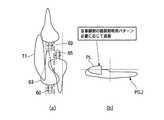
図1は本発明に係る車両用灯具の概念を側面視(a)、正面視(b)で示した説明図、図2は図1に示した車両用灯具によって形成される配光パターンを(a)(b)(c)で示した説明図である。
車両用灯具100は、光を出射する光源ユニット11を備え、光源ユニット11からの光を前方に照射してハイビーム配光パターンP(H)を形成する。ハイビーム配光パターンP(H)は、互いに異なる領域を照射する少なくとも2つ以上の照射パターンを有している。本実施形態では、3つの照射パターンPL,PC,PRを有する場合を例に説明する。DESCRIPTION OF EMBODIMENTS Hereinafter, a preferred embodiment of a vehicular lamp according to the present invention will be described with reference to the drawings.
FIG. 1 is an explanatory view showing a concept of a vehicular lamp according to the present invention in a side view (a) and a front view (b), and FIG. 2 shows a light distribution pattern formed by the vehicular lamp shown in FIG. It is explanatory drawing shown by a) (b) (c).
The
光源ユニット11には後述する制御部が接続され、制御部はそれぞれの照射パターンPL,PC,PRを選択的に点消灯制御可能としている。本実施形態において、照射パターンPL,PC,PRは、車両用灯具左側前方に照射される左側照射パターンPLと、車両用灯具右側前方に照射される右側照射パターンPRと、左側照射パターンPLと右側照射パターンPRの間を照射する中央照射パターンPCとを備える。したがって、制御部は、図2(a)〜(c)に示すように、左側照射パターンPL、右側照射パターンPR及び中央照射パターンPCを選択的に点消灯制御可能としている。なお、図中、P(L)は、ロービーム配光パターンを示す。 A control unit, which will be described later, is connected to the
以下では、まず本実施形態の車両用灯具として適用可能な具体的構成を示す。
図1に示すように、光源ユニット11は、垂直基台13を有し、垂直基台13の一方の面には車両左側に照射され左側照射パターンPLを形成する光を出射する第1LED(第1の発光部)15と、車両右側に照射され右側照射パターンPRを形成する光を出射する第2LED(第2の発光部)17と、左側照射パターンPLと右側照射パターンPRとの間に照射され中央照射パターンPCを形成する光を出射する第3LED(第3の発光部)19とを備える。光源ユニット11は、第1の発光部、第2の発光部、及び第3の発光部である第1LED15、第2LED17、第3LED19を備えることで、容易な点消灯制御により、左側照射パターンPL、右側照射パターンPR、中央照射パターンPCを簡素な装置構成で形成可能としている。なお、図1中、20は投影レンズを示す。Below, the specific structure applicable as a vehicle lamp of this embodiment is shown first.
As shown in FIG. 1, the
すなわち、本実施形態では、光源ユニット11の第1、第2及び第3LED15,17,19の発光面形状が投影レンズ20によって前方に投影され、各LED15,17,19の発光面形状と相似した配光パターンが前方に照射される。一般には、光源としてのLEDは点消灯の繰り返しに強いため長期間にわたる使用に十分耐えることができ好ましい。またLEDを用いることによりさほど広い設置スペースが必要ないため、車両用灯具全体を小型することもできる。また、投影レンズ(光学系)20を用いてLED15,17,19の発光面形状を投影して発光面形状と相似した照射パターンを前方に照射することにより、簡単な構成で特定形状の配光パターンを容易に得ることが可能である。 That is, in the present embodiment, the light emitting surface shape of the first, second, and
図3は図1に示した光源ユニットの基本構成に加え、反射部を備えた変形例を示す平面図である。
光源ユニット11は、第1LED15から出射した光を車両左側に照射して左側照射パターンPLを形成する第1の反射部21と、第2LED17から出射した光を車両右側に照射して右側照射パターンPRを形成する第2の反射部23と、第3LED19から出射した光を照射して中央照射パターンPCを形成する第3の反射部25とを備えることが好ましい。なお、図3中、26はカットオフラインを形成するシェードを示す。なお、本実施形態では、ハイビーム配光パターンを形成するものであるため、シェード26は基本的には不必要である。例えば、シェード26が鉛直方向に可動する可動シェードであり、光源ユニット11からハイビーム及びロービームを選択的に形成する場合には、このシェード26を可動させるように構成してもよい。FIG. 3 is a plan view showing a modified example provided with a reflecting portion in addition to the basic configuration of the light source unit shown in FIG.
The
これにより、第1LED15、第2LED17、第3LED19から出射される光を、それぞれ最適な左側照射パターンPL、最適な右側照射パターンPR、最適な中央照射パターンPCとして形成することが可能となる。 Thereby, the light emitted from the
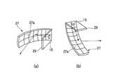
図4は、パラボラ型リフレクタを用いた場合の変形例であって、(a)は縦断面を、そして(b),(c)は正面視を示した説明図、図5はパラボラ型リフレクタにおけるLEDの横置き構造を(a)、縦置き構造を(b)に示した要部拡大斜視図である。
図3に示すように、それぞれの第1LED15、第2LED17、第3LED19毎に複数の反射部(リフレクタ)21,23,25が設けられる他に、図4に示すように、パラボラ型リフレクタ27とすることにより、複数のLEDからの出射光を、単一構造の反射部によって、上記同様の左側照射パターンPL、右側照射パターンPR、中央照射パターンPCを形成することが可能となる。この場合、それぞれの第1LED15、第2LED17、第3LED19は、パラボラ型リフレクタ27のそれぞれの焦点Fに配置される。FIG. 4 is a modification when a parabolic reflector is used, where (a) is a longitudinal section, and (b) and (c) are explanatory views showing a front view, and FIG. 5 is a parabolic reflector. It is the principal part expansion perspective view which showed the horizontal installation structure of LED in (a) and the vertical installation structure in (b).
As shown in FIG. 3, each of the
これにより、反射部の構造を小型・簡素にし、かつ部品点数を減らして装置コストを安価にすることが可能となる。この場合、LEDの取付構造としては、図5(a)に示すように、LED(例えば第1LED15)を、パラボラ型リフレクタ27の反射面27aに対面して垂直配置される基台29に、垂直配置してもよく、また、図5(b)に示すように、パラボラ型リフレクタ27の反射面27aに対面して水平配置される基台29に、水平配置してもよい。縦置きとすれば、光源ユニット11の全高を低く抑えることができ、横置きとすれば、光源ユニット11の車両幅方向の寸法を狭くすることができる。 As a result, the structure of the reflecting portion can be reduced in size and simplicity, and the number of parts can be reduced to reduce the apparatus cost. In this case, as an LED mounting structure, as shown in FIG. 5A, the LED (for example, the first LED 15) is vertically disposed on a base 29 that is vertically disposed facing the reflecting
図6は制御系の概略構成を表すブロック図である。
本実施の形態に係る車両用灯具100は、自車両前方に位置する物体を検出する検出装置31をさらに備えることが好ましい。上記した制御部33は、検出装置31の検出結果に応じて、少なくとも2つ以上の照射パターンを選択的に点消灯制御可能とする。この他、制御系は、画像解析部35を有している。検出装置31は、例えばCCDカメラが用いられ、車両が走行する前方の画像を撮像できるように設置されている。検出装置31としては、これ以外にも各種電磁波を用いたレーダを用いて車両や歩行者の位置を特定したり、各車両に通信機を備え車両間通信を行うことにより車両の位置を特定するようにしてもよい。以下では、まず画像を撮像した場合の例について説明する。FIG. 6 is a block diagram showing a schematic configuration of the control system.
The
検出装置31で撮像された車両前方の画像は、画像信号化されて画像解析部35に入力される。画像解析部35は、検出装置31から送信された画像信号を解析し、車両の前方に存在する他の車両までの距離及び角度を基に車両の位置を算出する。制御部33は、画像解析部35からの出力信号を受け、画像解析部35が算出した距離値及び角度値から、光源ユニット11を制御する制御信号を生成する。制御部33が生成した制御信号は、光源ユニット11に送られる。具体的には、制御部33は、光源ユニット11のハイビームおよびロービームに負荷する電圧量を算出し、光源ユニット11の第1LED15、第2LED17、第3の反射部25に算出された電圧を供給する。 An image ahead of the vehicle captured by the
このような検出装置31を備えた制御系によれば、制御部33が、検出装置31の検出結果に応じて照射パターンを選択的に点消灯制御するので、自車両前方の状況検出結果に応じて、制御部33が自動で最適なハイビーム配光パターンを選択でき、ドライバーに煩雑な選択操作を強いることなく、最良な照射状態への設定が可能となり、車両走行の安全性、快適性を向上させることができる。 According to the control system including such a
図7は制御系の他の例を表すブロック図である。
また、制御系は、前方の障害物を検出するレーダ41及び検出装置31と、車速を検出する車速センサ43とを有し、検出装置31等によって検出された障害物及び車速センサ43で検出された車速に応じて、制御部33によって照射パターンを選択的に点消灯制御するものであってもよい。FIG. 7 is a block diagram showing another example of the control system.
The control system also includes a
図8は制御系の更に他の例を表すブロック図である。
制御系は、更に、制御部33に加え、検出装置31であるIRカメラと、判定部45と、位置検出部47と、照射状態制御手段49と、アクチュエータ51と、マーカ照射部53とを備えるものであってもよい。検出装置31は、車両前方を撮像して、歩行者などの物体を検出する。判定部45は、検出装置31により撮像された画像の輝度値、物体の幾何学的形状、および、物体の移動の有無に基づいて、物体が歩行者であるという確信の度合い(確信度)を算出する。照射状態制御手段49は、判定部45により判定された確信度が低い場合には、マーカ照射部53によって物体を照射する際に、照射光量を増大させる時間を長くする。このような制御系によれば、検出装置31により検出された物体が歩行者であるという確信度を算出し、算出された確信度に基づいて、検出された物体を照射する方法を変更するので、歩行者ではない物体に対して光が照射されることに起因する運転者の視線誘導が緩和可能となる。FIG. 8 is a block diagram showing still another example of the control system.
In addition to the
次に、本実施形態に係る車両用灯具100の作用について説明する。
図9は単独走行時における路面照射範囲を(a)、配光パターンを(b)に示した説明図、図10は対向車有りの時の路面照射範囲を(a)、配光パターンを(b)に示した説明図、図11は先行車有りの時の路面照射範囲を(a)、配光パターンを(b)に示した説明図、図12は先行車及び対向車有りの時の路面照射範囲を(a)、配光パターンを(b)に示した説明図である。
車両60に搭載された車両用灯具100は、単独走行時、検出装置31により、歩行者、先行車、対向車がなれないと、第1LED15、第2LED17、第3LED19が制御部33によって点灯され、図9(a)に示す路面照射範囲61で、図9(b)に示すハイビーム配光パターンP(H)を形成する。なお、図中、63はロービーム配光パターンP(L)の路面照射範囲を示す。これにより、従来と同様の遠方視認性の良好なハイビーム配光パターンP(H)が得られることになる。Next, the operation of the
FIG. 9 is an explanatory diagram showing the road surface irradiation range when traveling alone (a) and the light distribution pattern in (b). FIG. 10 shows the road surface irradiation range when there is an oncoming vehicle (a) and the light distribution pattern ( b), FIG. 11 is a road surface irradiation range when a preceding vehicle is present (a), a light distribution pattern is an explanatory diagram illustrated in (b), and FIG. 12 is a preceding vehicle and an oncoming vehicle. It is explanatory drawing which showed the road surface irradiation range to (a) and the light distribution pattern to (b).
When the
一方、対向車が有る場合には、検出装置31によって対向車65が検出されると、制御部33が第2LED17を消灯させ、第1LED15、第3LED19を点灯する。これにより、図10(a)に示す路面照射範囲67で、図10(b)に示す左側照射パターンPL、中央照射パターンPCが形成される。このように、照射パターンが、左側照射パターンPLと、右側照射パターンPRと、中央照射パターンPCとを備え、制御部33が、これら照射パターンを選択的に点消灯制御するので、対向車65の眩しさを軽減し、遠方視認性を向上させることができる。 On the other hand, when there is an oncoming vehicle, when the oncoming
図11に示すように、先行車69が有る場合には、検出装置31が先行車69を検出し、その検出結果に応じて制御部33が、第3LED19を消灯し、第1LED15、第2LED17を点灯制御する。これにより、図11(a)に示す路面照射範囲71,73で、図11(b)に示す左側照射パターンPL、右側照射パターンPRが形成される。このように、検出装置31が自車両の正面前方に位置する先行車69を物体として検出した場合、制御部33が中央照射パターンPCを消灯するので、先行車69におけるバックミラーに反射するハイビームの眩しさを低減させることができる。また、この場合の配光パターンは、左右何れかのハイビームを消灯してもよい。 As shown in FIG. 11, when there is a preceding
さらに、図12に示すように、先行車69と対向車65が有る場合には、検出装置31が、先行車69と対向車65を検出し、制御部33が第2LED17、第3LED19を消灯し、第1LED15のみを点灯制御する。これにより、図12(a)に示す路面照射範囲71で、図12(b)に示す左側照射パターンPLが形成される。このように、照射パターンが、左側照射パターンPLと、右側照射パターンPRと、中央照射パターンPCとを備え、制御部33が、これら照射パターンを選択的に点消灯制御し、左側照射パターンPLのみを点灯するので、先行車69、対向車65の眩しさを軽減させ、かつ歩行者視認性も向上させることができる。 Furthermore, as shown in FIG. 12, when there is a preceding
したがって、本実施形態の車両用灯具100によれば、ハイビーム配光パターンP(H)が、互いに異なる領域を照射する少なくとも2つ以上の照射パターンを有し、それら照射パターンを選択的に点消灯制御する制御部33を設けたので、歩行者、先行車69、或いは対向車65の有無に応じ、ハイビームの照射領域を最適に設定することが可能となる。すなわち、路肩側を照射領域とする左側照射パターンPLを点灯させれば、ドライバーが歩行者をハッキリ確認でき、歩行者視認性を向上させることができる。一方、路肩側を照射領域とする左側照射パターンPLを消灯制御すれば、歩行者の眩しさを軽減させることもできる。このように、歩行者、先行車69、対向車65の眩しさを軽減させたり、歩行者の視認性を向上させたり、走行状況に応じた最適なハイビーム照射状態を実現させることができる。 Therefore, according to the
なお、上記の実施形態では、照射バターンが、左側照射パターンPL、右側照射パターンPR、及び中央照射パターンPCの3つに分割される場合を例に説明したが、照射パターンは、それ以外の複数、例えば、左側照射パターンPL、右側照射パターンPRの2つの照射パターンのみに分割されるものであってもよい。この場合、分割の境界は、上記中央照射パターンPCの中央となる。このような照射パターンを2分割する車両用灯具によれば、制御部33が、検出装置31の検出結果に応じて、左側照射パターンPL及び右側照射パターンPRを選択的に点消灯制御する。これにより、歩行者や対向車65の眩しさを軽減させたり、ドライバーによる歩行者視認性を向上させることができる。 In the above-described embodiment, the case where the irradiation pattern is divided into the left irradiation pattern PL, the right irradiation pattern PR, and the central irradiation pattern PC has been described as an example. For example, it may be divided into only two irradiation patterns, a left irradiation pattern PL and a right irradiation pattern PR. In this case, the division boundary is the center of the central irradiation pattern PC. According to the vehicular lamp that divides such an irradiation pattern into two parts, the
そして、照射パターンが2分割される車両用灯具では、検出装置31が対向車65を物体として検出した場合、左側照射パターンPL及び右側照射パターンPRの何れか一方を消灯するようにする。これにより、対向車65の眩しさを軽減させることができる。 In the vehicular lamp in which the irradiation pattern is divided into two, when the
また、照射パターンが2分割される車両用灯具では、光源ユニット11が、車両左側に照射され左側照射パターンPLを形成する光を出射する第1LED15と、車両右側に照射され右側照射パターンPRを形成する光を出射する第2LED17とを備えて形成される。これにより、第1LED15と第2LED17との容易な点消灯制御により、左側照射パターンPL、右側照射パターンPRを簡素な装置構成で形成することができる。 Further, in the vehicular lamp in which the irradiation pattern is divided into two, the
さらに、照射パターンが2分割される車両用灯具では、第1LED15から出射した光を反射して車両左側に照射することにより左側照射パターンPLを形成する第1の反射部21と、第2LED17から出射した光を反射して車両右側に照射することにより右側照射パターンPRを形成する第2の反射部23とを備えることが好ましい。これにより、第1LED15、第2LED17から出射される光を、それぞれ最適な左側照射パターンPL、最適な右側照射パターンPRとして形成することができる。 Further, in the vehicular lamp in which the irradiation pattern is divided into two, the light emitted from the
次に、図示は省略するが、配光パターンを選択的に照射する他の実施形態を説明する。
上記の実施の形態では、複数の第1LED15、第2LED17等を備え、これらLEDを選択的に点消灯制御する例を説明したが、本発明に係る車両用灯具は、例えば一つの光源を備え、この光源から出射される光を、方向変換装置によって複数の所望照射領域に同時に照射する構成としてもよい。この場合、方向変換装置は、多数の反射反射素子を有し、反射素子は例えば、1つの共通支持体上に配置されている。反射素子は、相互に無関係に支持体に対して相対的に、少なくとも2つの所定位置間で可動する。反射素子のそれぞれは、例えば、それに配属された電磁的調整操作素子によりそれの少なくとも2つの位置間で可動である。方向変換装置は所謂DMD、Digital Mirror Deviceとして構成されている。Next, although illustration is omitted, another embodiment for selectively irradiating a light distribution pattern will be described.
In the above embodiment, an example in which a plurality of
反射素子は、電磁素子へ電圧が印加されるか否かにより、調整操作素子と反射素子との間で作用する電磁力で所定の位置に可動する。このような方向変換装置を備えた車両用灯具によれば、光源からの光を所望の反射素子に反射させて、所望の数・形状に配光パターンが分割されるハイビーム配光パターンP(H)を得ることができる。 The reflecting element is moved to a predetermined position by an electromagnetic force acting between the adjusting operation element and the reflecting element depending on whether or not a voltage is applied to the electromagnetic element. According to the vehicular lamp provided with such a direction changing device, the light from the light source is reflected by a desired reflection element, and the light distribution pattern is divided into a desired number and shape. ) Can be obtained.
次に、上記実施形態の車両用灯具によるロービーム配光パターンとハイビーム配光パターンとを比較した結果を説明する。
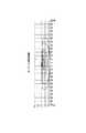
図13はロービームの等照度曲線図、図14はロービームの路面照度分布図、図15は自車両側をハイビームとした等照度曲線図、図16は自車両側をハイビームとした路面照度分布図である。
上記した実施形態の車両用灯具100において、ロービーム照射時には、図13に示すように、カットオフラインが垂直スケールH近傍で抑制され、それより上方にはビームが照射されていない。また、前方距離では、図14に示すように、光軸の左側の90mまでが照射領域となる。Next, the result of comparing the low beam distribution pattern and the high beam distribution pattern by the vehicle lamp of the above embodiment will be described.
13 is a low beam iso-illuminance curve diagram, FIG. 14 is a low beam road surface illumination distribution diagram, FIG. 15 is an iso-illumination curve diagram with the host vehicle side being a high beam, and FIG. is there.
In the
一方、図15に示すように、自車線側のみをハイビームとした場合(図2(b)に示す配光パターン)には、カットオフラインの上方で、垂直スケールHから上方へ垂直スケール5の高さまでビームが増大する。増大する左方の照射領域は、光軸を境に急峻に増大する。また、路面照度分布では、図16に示すように、150m前方まで照射領域の増大が知見された。 On the other hand, as shown in FIG. 15, when only the own lane side is a high beam (light distribution pattern shown in FIG. 2B), the
このように、選択的にハイビームとした場合のほうが、単なるロービーム照射時よりも、照射領域が拡がり遠方視認性を向上させることができる。また、ハイビームとした場合でも、選択的に所定の照射領域に照射される光をカットすることにより、遠方視認性を高めつつ、対向車、先行者等に眩しさを与えないようにすることが可能となる。 As described above, when the high beam is selectively used, the irradiation region is expanded and the distant visibility can be improved as compared with the case of simple low beam irradiation. In addition, even when a high beam is used, it is possible to prevent distant glare from oncoming vehicles and the preceding person while improving the distance visibility by selectively cutting the light irradiated to the predetermined irradiation area. It becomes.
11…光源ユニット
15…第1LED(第1の発光部)
17…第2LED(第2の発光部)
19…第3LED(第3の発光部)
21…第1の反射部
23…第2の反射部
25…第3の反射部
31…検出装置
33…制御部
69…先行車
100…車両用灯具
P(H)…ハイビーム配光パターン
PC…中央照射パターン(照射パターン)
PL…左側照射パターン(照射パターン)
PR…右側照射パターン(照射パターン)11 ...
17 ... 2nd LED (2nd light emission part)
19 ... 3rd LED (3rd light emission part)
DESCRIPTION OF
PL ... Left side irradiation pattern (irradiation pattern)
PR ... Right irradiation pattern (irradiation pattern)
Claims (9)
Translated fromJapanese前記ハイビーム配光パターンは、カットオフラインの上方の互いに異なる領域を照射する少なくとも2つ以上の照射パターンを有し、
前記少なくとも2つ以上の照射パターンを選択的に点消灯制御する制御部と、
自車両前方に位置する物体を検出する検出装置とを備え、
前記制御部は、前記検出装置の検出結果に応じて前記少なくとも2つ以上の照射パターンを選択的に点消灯制御し、
前記光源ユニットは前記少なくとも2つ以上の照射パターンを形成する2以上の発光部を有し、
前記各発光部は、光を照射するLEDと、前記LEDの発光面形状を投影して前記発光面形状と相似した照射パターンを前方に照射する光学系とを備え、
前記少なくとも2つ以上の照射パターンは、前記車両用灯具左側前方に照射される左側照射パターンと、前記車両用灯具右側前方に照射される右側照射パターンと、を備え、
前記制御部は、前記検出装置の検出結果に応じて、前記左側照射パターン及び前記右側照射パターンを選択的に点消灯制御することを特徴とする車両用灯具。A vehicular lamp that includes a light source unit that emits light and irradiates light from the light source unit forward to form a high beam light distribution pattern,
The high beam light distribution pattern has at least two irradiation patterns that irradiate different areas above the cutoff line,
A controller for selectively turning on / off the at least two irradiation patterns;
A detection device for detecting an object located in front of the host vehicle,
The control unit selectively turnson and off the at least two irradiation patterns according to a detection result of the detection device;
The light source unit has two or more light emitting portions that form the at least two irradiation patterns,
Each light emitting unit includes an LED that emits light, and an optical system that projects a light emitting surface shape of the LED and irradiates an irradiation pattern similar to the light emitting surface shape forward,
The at least two or more irradiation patterns include a left side irradiation pattern irradiated on the left side front of the vehicle lamp, and a right side irradiation pattern irradiated on the right side front of the vehicle lamp,
The vehicle lamp according to claim 1, wherein the controller selectively controls turning on and off the left side irradiation pattern and the right side irradiation pattern according to a detection result of the detection device.
前記ハイビーム配光パターンは、カットオフラインの上方の互いに異なる領域を照射する少なくとも2つ以上の照射パターンを有し、 The high beam light distribution pattern has at least two irradiation patterns that irradiate different areas above the cutoff line,
前記少なくとも2つ以上の照射パターンを選択的に点消灯制御する制御部と、 A controller for selectively turning on / off the at least two irradiation patterns;
自車両前方に位置する物体を検出する検出装置とを備え、 A detection device for detecting an object located in front of the host vehicle,
前記制御部は、前記検出装置の検出結果に応じて前記少なくとも2つ以上の照射パターンを選択的に点消灯制御し、 The control unit selectively turns on and off the at least two irradiation patterns according to a detection result of the detection device;
前記光源ユニットは前記少なくとも2つ以上の照射パターンを形成する2以上の発光部を有し、 The light source unit has two or more light emitting portions that form the at least two irradiation patterns,
前記各発光部は、光を照射するLEDと、前記LEDの発光面形状を投影して前記発光面形状と相似した照射パターンを前方に照射する光学系とを備え、 Each light emitting unit includes an LED that emits light, and an optical system that projects a light emitting surface shape of the LED and irradiates an irradiation pattern similar to the light emitting surface shape forward,
前記少なくとも2つ以上の照射パターンは、前記車両用灯具左側前方に照射される左側照射パターンと、前記車両用灯具右側前方に照射される右側照射パターンと、前記左側照射パターンと前記右側照射パターンの間を照射する中央照射パターンと、を備え、 The at least two or more irradiation patterns include a left irradiation pattern that is irradiated to the left front of the vehicular lamp, a right irradiation pattern that is irradiated to the front right of the vehicular lamp, the left irradiation pattern, and the right irradiation pattern. And a central irradiation pattern for irradiating between,
前記制御部は、前記左側照射パターン、前記右側照射パターン及び前記中央照射パターンを選択的に点消灯制御することを特徴とする車両用灯具。 The said control part selectively turns on and off the said left side irradiation pattern, the said right side irradiation pattern, and the said center irradiation pattern, The vehicle lamp characterized by the above-mentioned.
Priority Applications (5)
| Application Number | Priority Date | Filing Date | Title |
|---|---|---|---|
| JP2005379702AJP4624257B2 (en) | 2005-12-28 | 2005-12-28 | Vehicle lighting |
| US11/641,851US7510310B2 (en) | 2005-12-28 | 2006-12-20 | Vehicle lighting device |
| DE102006061637.5ADE102006061637B4 (en) | 2005-12-28 | 2006-12-27 | The vehicle lighting device |
| CNA2006100643711ACN101008481A (en) | 2005-12-28 | 2006-12-28 | Vehicle lighting device |
| FR0655995AFR2895947B1 (en) | 2005-12-28 | 2006-12-28 | LIGHTING DEVICE FOR VEHICLE |
Applications Claiming Priority (1)
| Application Number | Priority Date | Filing Date | Title |
|---|---|---|---|
| JP2005379702AJP4624257B2 (en) | 2005-12-28 | 2005-12-28 | Vehicle lighting |
Publications (2)
| Publication Number | Publication Date |
|---|---|
| JP2007179969A JP2007179969A (en) | 2007-07-12 |
| JP4624257B2true JP4624257B2 (en) | 2011-02-02 |
Family
ID=38136013
Family Applications (1)
| Application Number | Title | Priority Date | Filing Date |
|---|---|---|---|
| JP2005379702AExpired - Fee RelatedJP4624257B2 (en) | 2005-12-28 | 2005-12-28 | Vehicle lighting |
Country Status (5)
| Country | Link |
|---|---|
| US (1) | US7510310B2 (en) |
| JP (1) | JP4624257B2 (en) |
| CN (1) | CN101008481A (en) |
| DE (1) | DE102006061637B4 (en) |
| FR (1) | FR2895947B1 (en) |
Cited By (5)
| Publication number | Priority date | Publication date | Assignee | Title |
|---|---|---|---|---|
| EP2818793A2 (en) | 2013-06-26 | 2014-12-31 | Stanley Electric Co., Ltd. | Light-emitting apparatus and vehicle headlamp system |
| EP2821282A2 (en) | 2013-07-03 | 2015-01-07 | Stanley Electric Co., Ltd. | Light source apparatus, vehicle headlamp and vehicle headlamp system |
| EP2826667A1 (en) | 2013-07-03 | 2015-01-21 | Stanley Electric Co., Ltd. | Vehicle headlamp and vehicle headlamp system |
| CN108613110A (en)* | 2016-12-22 | 2018-10-02 | 深圳市绎立锐光科技开发有限公司 | A kind of light-source system, automobile lighting system and control method |
| US10464470B2 (en) | 2016-05-17 | 2019-11-05 | Stanley Electric Co., Ltd. | Vehicle lamp |
Families Citing this family (118)
| Publication number | Priority date | Publication date | Assignee | Title |
|---|---|---|---|---|
| DE102007028658A1 (en) | 2007-06-21 | 2008-12-24 | Hella Kgaa Hueck & Co. | A method of controlling a headlamp assembly for a vehicle having separate headlamps for a low beam and a high beam |
| US7914187B2 (en)* | 2007-07-12 | 2011-03-29 | Magna Electronics Inc. | Automatic lighting system with adaptive alignment function |
| JP4321643B2 (en)* | 2007-08-10 | 2009-08-26 | トヨタ自動車株式会社 | Perimeter monitoring device |
| DE102007038563A1 (en)* | 2007-08-16 | 2009-02-19 | Daimler Ag | Lighting system for a motor vehicle |
| DE102007040810A1 (en)* | 2007-08-29 | 2009-03-05 | Continental Automotive Gmbh | Method for operating headlamps in a motor vehicle |
| JP5069985B2 (en)* | 2007-09-13 | 2012-11-07 | 株式会社小糸製作所 | Vehicle headlamp lamp unit and vehicle headlamp |
| US8007146B2 (en)* | 2007-09-14 | 2011-08-30 | Koito Manufacturing Co., Ltd. | Vehicle lamp |
| JP4726883B2 (en)* | 2007-11-16 | 2011-07-20 | トヨタ自動車株式会社 | Vehicle headlamp |
| FR2923890A1 (en) | 2007-11-16 | 2009-05-22 | Valeo Vision Sa | LIGHTING DEVICE FOR MOTOR VEHICLE |
| JP2009179113A (en)* | 2008-01-29 | 2009-08-13 | Koito Mfg Co Ltd | Head lamp device for vehicle and its control method |
| JP4995748B2 (en)* | 2008-01-29 | 2012-08-08 | 株式会社小糸製作所 | Vehicle headlamp device and control method for vehicle headlamp device |
| DE102008010028B4 (en)* | 2008-02-20 | 2016-12-08 | Hella Kgaa Hueck & Co. | Projection headlights for vehicles |
| JP2009214812A (en)* | 2008-03-12 | 2009-09-24 | Koito Mfg Co Ltd | Vehicular headlight device and its control method |
| DE102008014182A1 (en)* | 2008-03-14 | 2009-09-17 | Daimler Ag | Method for driving light control of a vehicle |
| JP5280074B2 (en)* | 2008-03-14 | 2013-09-04 | 株式会社小糸製作所 | Vehicle headlamp device |
| EP3296155A1 (en)* | 2008-05-08 | 2018-03-21 | Koito Manufacturing Co., Ltd. | Automotive headlamp apparatus |
| JP5248189B2 (en)* | 2008-05-08 | 2013-07-31 | 株式会社小糸製作所 | Vehicle headlamp device and control method thereof |
| JP5111229B2 (en)* | 2008-05-08 | 2013-01-09 | 株式会社小糸製作所 | Vehicle headlamp device and control method thereof |
| JP2009283408A (en) | 2008-05-26 | 2009-12-03 | Koito Mfg Co Ltd | Vehicular headlight |
| DE102008025463A1 (en)* | 2008-05-28 | 2009-12-10 | Delvis Gmbh | Radiating unit i.e. Xenon-lamp, for head light i.e. motor vehicle head light, has shadowing devices superimposed to radiating surfaces, where shadowing devices are controlled for variable optical shadowing of radiating surfaces |
| JP2010000957A (en)* | 2008-06-20 | 2010-01-07 | Koito Mfg Co Ltd | Headlight device for vehicle |
| DE102008034166A1 (en)* | 2008-07-22 | 2010-01-28 | Hella Kgaa Hueck & Co. | Method and device for Euting a suitable light distribution of the light emitted by at least one headlight of a vehicle light |
| JP5199781B2 (en) | 2008-08-11 | 2013-05-15 | 株式会社小糸製作所 | Vehicle headlamp device |
| JP5087500B2 (en)* | 2008-08-27 | 2012-12-05 | 株式会社小糸製作所 | Vehicle lamp unit |
| US8274226B1 (en)* | 2008-10-06 | 2012-09-25 | Tomar Electronics, Inc. | System and method of integrating an LED spotlight |
| JP5394700B2 (en)* | 2008-11-13 | 2014-01-22 | 株式会社小糸製作所 | Vehicle headlamp |
| JP5133862B2 (en) | 2008-12-09 | 2013-01-30 | 株式会社小糸製作所 | Lighting fixtures for vehicles |
| JP5133861B2 (en) | 2008-12-09 | 2013-01-30 | 株式会社小糸製作所 | Lighting fixtures for vehicles |
| JP2010192411A (en)* | 2009-02-20 | 2010-09-02 | Koito Mfg Co Ltd | Headlamp for vehicle |
| JP5543720B2 (en)* | 2009-03-06 | 2014-07-09 | 株式会社小糸製作所 | Vehicle headlamp device |
| US20100266326A1 (en)* | 2009-04-21 | 2010-10-21 | Chuang Cheng-Hua | Mark-erasable pen cap |
| DE102009026571A1 (en)* | 2009-05-29 | 2010-12-02 | Robert Bosch Gmbh | Method and device for vehicle-based lighting in poorly lit traffic environments |
| JP5478962B2 (en)* | 2009-07-01 | 2014-04-23 | 株式会社小糸製作所 | Vehicle headlamp device |
| JP5317871B2 (en)* | 2009-07-10 | 2013-10-16 | 株式会社小糸製作所 | Vehicle headlamp device |
| JP2011040495A (en) | 2009-08-07 | 2011-02-24 | Koito Mfg Co Ltd | Light emitting module |
| DE102009037559A1 (en)* | 2009-08-13 | 2011-02-17 | Automotive Lighting Reutlingen Gmbh | Headlamp with a LED-Teilfernlichtmodul |
| JP2011037414A (en)* | 2009-08-18 | 2011-02-24 | Koito Mfg Co Ltd | Headlamp system for vehicle |
| FR2950579B1 (en)* | 2009-09-29 | 2012-05-11 | Valeo Vision | METHOD FOR CONTROLLING A LIGHTING PROJECTOR FOR A VEHICLE |
| JP2011082072A (en) | 2009-10-08 | 2011-04-21 | Koito Mfg Co Ltd | Vehicle headlight |
| JP5398507B2 (en) | 2009-12-16 | 2014-01-29 | 株式会社小糸製作所 | Vehicle headlamp device |
| JP5513915B2 (en) | 2010-02-05 | 2014-06-04 | 株式会社小糸製作所 | Vehicle headlamp |
| JP5457219B2 (en) | 2010-02-16 | 2014-04-02 | 株式会社小糸製作所 | Optical unit |
| RU2553271C2 (en)* | 2010-03-23 | 2015-06-10 | Конинклейке Филипс Электроникс Н.В. | Built-in lighting unit |
| JP5722882B2 (en) | 2010-04-13 | 2015-05-27 | 株式会社小糸製作所 | Optical unit |
| JP5467917B2 (en) | 2010-04-23 | 2014-04-09 | 株式会社小糸製作所 | Lighting fixtures for vehicles |
| JP5519394B2 (en)* | 2010-05-10 | 2014-06-11 | 株式会社小糸製作所 | Lighting fixtures for vehicles |
| JP2011258406A (en) | 2010-06-09 | 2011-12-22 | Koito Mfg Co Ltd | Optical unit |
| JP5592183B2 (en) | 2010-07-16 | 2014-09-17 | 株式会社小糸製作所 | Vehicle lighting |
| US8536997B2 (en)* | 2010-08-12 | 2013-09-17 | General Electric Company | Vehicle lighting control apparatus and method |
| JP5716320B2 (en)* | 2010-08-26 | 2015-05-13 | 市光工業株式会社 | Vehicle headlamp and vehicle headlamp device |
| DE102010040650B4 (en)* | 2010-09-13 | 2020-08-13 | Robert Bosch Gmbh | Device and method for adjusting the lighting of a vehicle in the case of blind bends |
| US8972117B2 (en)* | 2010-11-12 | 2015-03-03 | Toyota Jidosha Kabushiki Kaisha | Vehicular light distribution control system and vehicular light distribution control method |
| KR101232308B1 (en)* | 2010-11-25 | 2013-02-13 | 에스엘 주식회사 | Apparatus and method for controlling head lamp for vehicles |
| DE102011118274B4 (en)* | 2010-12-03 | 2022-03-24 | Docter Optics Se | Headlight lens for a vehicle headlight |
| US10107466B2 (en) | 2010-12-03 | 2018-10-23 | Docter Optics Se | Headlight lens for a vehicle headlight |
| CN103249991B (en) | 2010-12-03 | 2016-04-06 | 博士光学欧洲股份公司 | Headlight lenses for vehicle headlights |
| WO2012072190A2 (en) | 2010-12-03 | 2012-06-07 | Docter Optics Gmbh | Optical component for illumination purposes |
| JP2012155891A (en)* | 2011-01-24 | 2012-08-16 | Koito Mfg Co Ltd | Optical unit and vehicular lamp |
| KR101792883B1 (en)* | 2011-07-13 | 2017-11-02 | 엘지이노텍 주식회사 | Apparatus and method for controlling high-lamp of vehicle |
| JP2013047091A (en)* | 2011-07-25 | 2013-03-07 | Sharp Corp | Lighting device and vehicle headlamp including the same |
| KR20130032686A (en)* | 2011-09-23 | 2013-04-02 | 현대모비스 주식회사 | A lamp apparatus for vehicles |
| KR20130047214A (en)* | 2011-10-31 | 2013-05-08 | 현대자동차주식회사 | Spot lighting unit, headlamp system with spot lighting unit, and lighting method using thereof |
| US10018323B2 (en) | 2011-11-11 | 2018-07-10 | Docter Optics Se | Vehicle headlight |
| US9599302B2 (en) | 2011-11-11 | 2017-03-21 | Docter Optics Se | Headlight lens for a vehicle headlight |
| DE102011055606A1 (en)* | 2011-11-22 | 2013-05-23 | Hella Kgaa Hueck & Co. | Method and control unit for controlling headlamps with adjustable vertical light-dark boundary for deblading objects |
| DE102011090181B4 (en)* | 2011-12-30 | 2018-02-15 | Automotive Lighting Reutlingen Gmbh | Headlight for a motor vehicle, which generates a partial high-beam light distribution with the aid of a reflection system |
| DE102012001017A1 (en)* | 2012-01-19 | 2013-07-25 | GM Global Technology Operations LLC (n. d. Gesetzen des Staates Delaware) | Method for controlling headlamp of motor vehicle, involves automatically changing photometric size of headlamp depending on vehicle environment condition, where vehicle environment condition comprises position relative to obstacle |
| JP2013161567A (en)* | 2012-02-02 | 2013-08-19 | Ichikoh Ind Ltd | Vehicle headlamp, and vehicle headlamp device |
| JP5894474B2 (en) | 2012-03-14 | 2016-03-30 | 株式会社小糸製作所 | Optical unit |
| JP6019643B2 (en)* | 2012-03-19 | 2016-11-02 | 市光工業株式会社 | Vehicle headlamp |
| JP5859893B2 (en)* | 2012-03-29 | 2016-02-16 | 株式会社小糸製作所 | Optical unit |
| JP5866242B2 (en) | 2012-04-02 | 2016-02-17 | 株式会社小糸製作所 | Vehicle lamp device |
| DE102012009596A1 (en) | 2012-05-15 | 2013-11-21 | Docter Optics Se | Method for producing a headlight lens |
| JP6075969B2 (en)* | 2012-05-22 | 2017-02-08 | 株式会社小糸製作所 | Vehicle headlamp |
| DE102013006707A1 (en) | 2012-05-26 | 2013-11-28 | Docter Optics Se | vehicle headlights |
| DE102012210157A1 (en)* | 2012-06-15 | 2013-12-19 | Robert Bosch Gmbh | Method and device for operating a headlamp for a motor vehicle |
| WO2014002630A1 (en)* | 2012-06-29 | 2014-01-03 | 株式会社小糸製作所 | Vehicle lamp and control method therefor |
| DE102012013730A1 (en)* | 2012-07-11 | 2014-01-16 | GM Global Technology Operations LLC (n. d. Gesetzen des Staates Delaware) | Headlight system for a motor vehicle |
| US9776587B2 (en)* | 2012-11-29 | 2017-10-03 | Here Global B.V. | Method and apparatus for causing a change in an action of a vehicle for safety |
| JP5547318B2 (en)* | 2013-03-07 | 2014-07-09 | 株式会社小糸製作所 | Vehicle headlight device and headlight control device |
| JP5547316B2 (en)* | 2013-03-07 | 2014-07-09 | 株式会社小糸製作所 | Vehicle headlight device and headlight control device |
| JP5547319B2 (en)* | 2013-03-07 | 2014-07-09 | 株式会社小糸製作所 | Vehicle headlight device and headlight control device |
| JP5547317B2 (en)* | 2013-03-07 | 2014-07-09 | 株式会社小糸製作所 | Vehicle headlight device and headlight control device |
| CN103175088B (en)* | 2013-03-19 | 2015-09-23 | 奇瑞汽车股份有限公司 | A kind of Dazzling-resistant high beam light |
| CN103192759B (en)* | 2013-04-22 | 2016-02-03 | 长安大学 | A kind of face matrix LED car lamp control system of nighttime meeting and control method thereof |
| CN103353092A (en)* | 2013-07-12 | 2013-10-16 | 哈尔滨固泰电子有限责任公司 | Polarized light compensation type automobile headlamp light distribution device and method |
| JP5698330B2 (en)* | 2013-10-16 | 2015-04-08 | 株式会社小糸製作所 | Vehicle headlamp |
| JP5636485B2 (en)* | 2013-10-21 | 2014-12-03 | 株式会社小糸製作所 | Lamp unit |
| CN103822151B (en)* | 2014-01-21 | 2016-08-17 | 漳浦桂宏工业有限公司 | A kind of vehicle intelligent lighting fixture |
| JP6271292B2 (en)* | 2014-02-25 | 2018-01-31 | 株式会社小糸製作所 | Vehicle lighting |
| JP6031468B2 (en)* | 2014-04-15 | 2016-11-24 | 株式会社豊田中央研究所 | Irradiation device |
| DE102014009253B4 (en) | 2014-06-20 | 2022-10-27 | Audi Ag | Method for controlling a light distribution of a headlight of a motor vehicle |
| DE102014216545B4 (en) | 2014-08-20 | 2017-04-27 | Automotive Lighting Reutlingen Gmbh | Headlight device with right and left different high beam modules |
| FR3026687B1 (en)* | 2014-10-02 | 2018-03-02 | Valeo Vision | OPTIMIZED INTENSITY PROFILE LIGHTING SYSTEM FOR MOTOR VEHICLE PROJECTOR |
| JP6514510B2 (en) | 2015-01-14 | 2019-05-15 | 株式会社小糸製作所 | Vehicle lamp |
| KR102340502B1 (en) | 2015-04-22 | 2021-12-17 | 에스엘 주식회사 | Lamp for vehicle |
| JP6571384B2 (en)* | 2015-05-14 | 2019-09-04 | スタンレー電気株式会社 | Lighting control device for vehicle headlamp, vehicle headlamp system |
| AT517415B1 (en)* | 2015-06-29 | 2017-04-15 | Zkw Group Gmbh | Control device for a lighting device of a motor vehicle and method for controlling such a lighting device |
| EP3118123B1 (en) | 2015-07-17 | 2019-01-16 | Goodrich Lighting Systems GmbH | Exterior helicopter light unit and method of operating an exterior helicopter light unit |
| JP6265183B2 (en)* | 2015-08-21 | 2018-01-24 | トヨタ自動車株式会社 | Vehicle headlamp device |
| US10331956B2 (en) | 2015-09-23 | 2019-06-25 | Magna Electronics Inc. | Vehicle vision system with detection enhancement using light control |
| KR102483571B1 (en)* | 2016-04-11 | 2023-01-02 | 현대모비스 주식회사 | Vehicle lamp |
| US9889790B2 (en)* | 2016-06-24 | 2018-02-13 | Gentex Corporation | Imaging system with adaptive high beam control |
| EP3301500B1 (en) | 2016-09-29 | 2023-09-06 | Valeo Vision | Lighting system of a motor vehicle and motor vehicle |
| FR3056486B1 (en)* | 2016-09-29 | 2018-10-12 | Valeo Vision | LIGHTING SYSTEM FOR MOTOR VEHICLE AND MOTOR VEHICLE |
| FR3056485B1 (en)* | 2016-09-29 | 2018-10-12 | Valeo Vision | LIGHTING SYSTEM FOR MOTOR VEHICLE AND MOTOR VEHICLE |
| DE102017211888A1 (en)* | 2017-07-12 | 2019-01-17 | Robert Bosch Gmbh | Method and device for adjusting a headlight of a vehicle |
| CN107521407B (en)* | 2017-08-24 | 2019-07-23 | 京东方科技集团股份有限公司 | A kind of vehicle head lamp control system and its control method, vehicle |
| EP3724027B1 (en)* | 2017-12-14 | 2021-05-26 | Lumileds LLC | Illuminant for vehicle headlight with automatic beam mode selection |
| EP3556662B1 (en)* | 2018-04-20 | 2022-10-12 | Goodrich Lighting Systems GmbH | Aircraft vertical stabilizer illumination light and method of operating an aircraft vertical stabilizer illumination light |
| US10704757B2 (en)* | 2018-10-19 | 2020-07-07 | Valeo North America, Inc. | Lighting unit for automotive headlamp |
| JP7204551B2 (en)* | 2019-03-19 | 2023-01-16 | 株式会社小糸製作所 | Vehicle monitoring system |
| US10715738B1 (en)* | 2019-04-30 | 2020-07-14 | Axon Enterprise, Inc. | Asymmetrical license plate reading (ALPR) camera system |
| WO2020223519A1 (en) | 2019-04-30 | 2020-11-05 | Axon Enterprise, Inc. | License plate reading system with enhancements |
| US11030472B2 (en) | 2019-04-30 | 2021-06-08 | Axon Enterprise, Inc. | Asymmetrical license plate reading (ALPR) camera system |
| WO2021124778A1 (en)* | 2019-12-16 | 2021-06-24 | 株式会社小糸製作所 | Automotive light fixture |
| JP7238829B2 (en)* | 2020-02-17 | 2023-03-14 | トヨタ自動車株式会社 | Vehicle headlight controller |
| KR20210144483A (en)* | 2020-05-22 | 2021-11-30 | 삼성전자주식회사 | Light emitting device and head lamp for vehicle comprising the same |
Family Cites Families (18)
| Publication number | Priority date | Publication date | Assignee | Title |
|---|---|---|---|---|
| FR1306770A (en)* | 1961-09-27 | 1962-10-19 | Telefunken Patent | Road lighting installation for motor vehicles fitted with partially obscured headlights |
| JP2862766B2 (en)* | 1993-08-03 | 1999-03-03 | 株式会社小糸製作所 | Light distribution control device for automotive headlamp |
| JP3075966B2 (en)* | 1995-08-04 | 2000-08-14 | 本田技研工業株式会社 | Headlight device for vehicles |
| JPH10151987A (en)* | 1996-11-25 | 1998-06-09 | Honda Access Corp | Forward lighting system of vehicle |
| DE19716784B4 (en)* | 1997-04-22 | 2006-05-18 | Automotive Lighting Reutlingen Gmbh | Headlamp system for vehicles |
| DE10009782B4 (en)* | 2000-03-01 | 2010-08-12 | Automotive Lighting Reutlingen Gmbh | Lighting device of a vehicle |
| JP3943308B2 (en)* | 2000-03-23 | 2007-07-11 | 株式会社小糸製作所 | Vehicle lamp and vehicle lamp system |
| JP3964104B2 (en)* | 2000-07-05 | 2007-08-22 | 株式会社小糸製作所 | Vehicle headlight system |
| JP3560540B2 (en)* | 2000-10-03 | 2004-09-02 | 株式会社デンソー | Automatic adjustment of the headlight optical axis direction for vehicles |
| DE10154407A1 (en)* | 2000-11-10 | 2002-06-06 | Denso Corp | Automatic control of the axis direction of headlights for vehicles |
| EP1219887B1 (en)* | 2000-12-25 | 2006-09-27 | Stanley Electric Co., Ltd. | Vehicle light capable of changing light distribution pattern between low-beam mode and high-beam mode by a movable shade and a reflecting surface |
| JP4024628B2 (en) | 2002-09-03 | 2007-12-19 | 株式会社小糸製作所 | Vehicle headlamp |
| JP4002159B2 (en) | 2002-09-03 | 2007-10-31 | 株式会社小糸製作所 | Vehicle headlamp |
| US7287887B2 (en)* | 2004-07-29 | 2007-10-30 | Koito Manufacturing Co., Ltd. | Vehicle headlamp |
| DE102005014953A1 (en)* | 2005-04-01 | 2006-10-05 | Audi Ag | Motor vehicle with a lighting device with variable illumination volume |
| DE102005041234A1 (en)* | 2005-08-31 | 2007-03-01 | Hella Kgaa Hueck & Co. | Headlight for vehicle, has optical units with characteristics in front of groups of sources in such a manner that different large light spots can be generated in traffic space by alternative switching on and off and/or dimming of sources |
| JP2007099222A (en)* | 2005-10-07 | 2007-04-19 | Koito Mfg Co Ltd | Vehicular lighting system |
| FR2894905B1 (en)* | 2005-10-25 | 2009-07-10 | Valeo Vision Sa | METHOD OF LIGHTING MODULE OF A ROAD AND PROJECTOR OF A VEHICLE IMPLEMENTING SAID METHOD |
- 2005
- 2005-12-28JPJP2005379702Apatent/JP4624257B2/ennot_activeExpired - Fee Related
- 2006
- 2006-12-20USUS11/641,851patent/US7510310B2/enactiveActive
- 2006-12-27DEDE102006061637.5Apatent/DE102006061637B4/ennot_activeExpired - Fee Related
- 2006-12-28CNCNA2006100643711Apatent/CN101008481A/enactivePending
- 2006-12-28FRFR0655995Apatent/FR2895947B1/enactiveActive
Cited By (8)
| Publication number | Priority date | Publication date | Assignee | Title |
|---|---|---|---|---|
| EP2818793A2 (en) | 2013-06-26 | 2014-12-31 | Stanley Electric Co., Ltd. | Light-emitting apparatus and vehicle headlamp system |
| EP2821282A2 (en) | 2013-07-03 | 2015-01-07 | Stanley Electric Co., Ltd. | Light source apparatus, vehicle headlamp and vehicle headlamp system |
| CN104276077A (en)* | 2013-07-03 | 2015-01-14 | 斯坦雷电气株式会社 | Light source apparatus, vehicle headlamp and vehicle headlamp system |
| EP2826667A1 (en) | 2013-07-03 | 2015-01-21 | Stanley Electric Co., Ltd. | Vehicle headlamp and vehicle headlamp system |
| CN104276077B (en)* | 2013-07-03 | 2018-04-24 | 斯坦雷电气株式会社 | Light supply apparatus, headlight for automobile, vehicle headlamp system |
| US10464470B2 (en) | 2016-05-17 | 2019-11-05 | Stanley Electric Co., Ltd. | Vehicle lamp |
| CN108613110A (en)* | 2016-12-22 | 2018-10-02 | 深圳市绎立锐光科技开发有限公司 | A kind of light-source system, automobile lighting system and control method |
| CN108613110B (en)* | 2016-12-22 | 2020-06-02 | 深圳市绎立锐光科技开发有限公司 | Light source system, automobile lighting system and control method |
Also Published As
| Publication number | Publication date |
|---|---|
| DE102006061637B4 (en) | 2015-07-16 |
| US20070147055A1 (en) | 2007-06-28 |
| JP2007179969A (en) | 2007-07-12 |
| FR2895947A1 (en) | 2007-07-13 |
| US7510310B2 (en) | 2009-03-31 |
| CN101008481A (en) | 2007-08-01 |
| DE102006061637A1 (en) | 2007-07-05 |
| FR2895947B1 (en) | 2012-07-20 |
Similar Documents
| Publication | Publication Date | Title |
|---|---|---|
| JP4624257B2 (en) | Vehicle lighting | |
| JP5438410B2 (en) | Vehicle headlamp device | |
| US9878655B2 (en) | Vehicle lamp | |
| JP5438405B2 (en) | Vehicle headlamp device | |
| JP4995748B2 (en) | Vehicle headlamp device and control method for vehicle headlamp device | |
| JP5424771B2 (en) | Light distribution control system for vehicle headlamps | |
| US9358918B2 (en) | Vehicle headlamp | |
| EP2266838B1 (en) | Vehicle headlamp apparatus | |
| CN115362086B (en) | Vehicle headlights | |
| CN102537807B (en) | Head lamp assembly and method for controlling the same | |
| JP2009179113A (en) | Head lamp device for vehicle and its control method | |
| JP2009214812A (en) | Vehicular headlight device and its control method | |
| JP5394901B2 (en) | Vehicle headlight system | |
| JP5372616B2 (en) | Light distribution control system for vehicle headlamps | |
| JP5107821B2 (en) | Vehicle headlamp device | |
| JP2010162960A (en) | Vehicle headlight device | |
| JP5430282B2 (en) | Light distribution control system for vehicle headlamps | |
| EP2100771B1 (en) | Vehicle headlight apparatus and method for controlling same | |
| EP2230128B1 (en) | Automotive headlamp apparatus for controlling light distribution pattern | |
| JP7084392B2 (en) | Vehicle lighting system, vehicle lighting control device, and vehicle lighting control method | |
| JP2010015837A (en) | Headlight device for vehicle | |
| JP5539784B2 (en) | VEHICLE LIGHT SYSTEM, CONTROL DEVICE, AND VEHICLE LIGHT | |
| JP5636483B2 (en) | Light distribution control system for vehicle headlamps | |
| JP2010143483A (en) | Vehicle headlight device and method for controlling the same | |
| KR20170027394A (en) | Lamp for vehicle and controlling method applied to the same |
Legal Events
| Date | Code | Title | Description |
|---|---|---|---|
| A621 | Written request for application examination | Free format text:JAPANESE INTERMEDIATE CODE: A621 Effective date:20080324 | |
| A977 | Report on retrieval | Free format text:JAPANESE INTERMEDIATE CODE: A971007 Effective date:20091106 | |
| A131 | Notification of reasons for refusal | Free format text:JAPANESE INTERMEDIATE CODE: A131 Effective date:20091125 | |
| A521 | Request for written amendment filed | Free format text:JAPANESE INTERMEDIATE CODE: A523 Effective date:20100115 | |
| A131 | Notification of reasons for refusal | Free format text:JAPANESE INTERMEDIATE CODE: A131 Effective date:20100525 | |
| A521 | Request for written amendment filed | Free format text:JAPANESE INTERMEDIATE CODE: A523 Effective date:20100723 | |
| TRDD | Decision of grant or rejection written | ||
| A01 | Written decision to grant a patent or to grant a registration (utility model) | Free format text:JAPANESE INTERMEDIATE CODE: A01 Effective date:20101026 | |
| A01 | Written decision to grant a patent or to grant a registration (utility model) | Free format text:JAPANESE INTERMEDIATE CODE: A01 | |
| A61 | First payment of annual fees (during grant procedure) | Free format text:JAPANESE INTERMEDIATE CODE: A61 Effective date:20101102 | |
| R150 | Certificate of patent or registration of utility model | Ref document number:4624257 Country of ref document:JP Free format text:JAPANESE INTERMEDIATE CODE: R150 Free format text:JAPANESE INTERMEDIATE CODE: R150 | |
| FPAY | Renewal fee payment (event date is renewal date of database) | Free format text:PAYMENT UNTIL: 20131112 Year of fee payment:3 | |
| LAPS | Cancellation because of no payment of annual fees |