JP4624227B2 - Communication terminal, mobile communication system, and communication control method - Google Patents
Communication terminal, mobile communication system, and communication control methodDownload PDFInfo
- Publication number
- JP4624227B2 JP4624227B2JP2005285231AJP2005285231AJP4624227B2JP 4624227 B2JP4624227 B2JP 4624227B2JP 2005285231 AJP2005285231 AJP 2005285231AJP 2005285231 AJP2005285231 AJP 2005285231AJP 4624227 B2JP4624227 B2JP 4624227B2
- Authority
- JP
- Japan
- Prior art keywords
- communication terminal
- communication
- temperature
- station
- base station
- Prior art date
- Legal status (The legal status is an assumption and is not a legal conclusion. Google has not performed a legal analysis and makes no representation as to the accuracy of the status listed.)
- Expired - Fee Related
Links
Images


Classifications
- H—ELECTRICITY
- H04—ELECTRIC COMMUNICATION TECHNIQUE
- H04W—WIRELESS COMMUNICATION NETWORKS
- H04W76/00—Connection management
- H04W76/10—Connection setup
- H04W76/14—Direct-mode setup
- H—ELECTRICITY
- H04—ELECTRIC COMMUNICATION TECHNIQUE
- H04W—WIRELESS COMMUNICATION NETWORKS
- H04W76/00—Connection management
- H04W76/20—Manipulation of established connections
- H—ELECTRICITY
- H04—ELECTRIC COMMUNICATION TECHNIQUE
- H04L—TRANSMISSION OF DIGITAL INFORMATION, e.g. TELEGRAPHIC COMMUNICATION
- H04L25/00—Baseband systems
- H04L25/02—Details ; arrangements for supplying electrical power along data transmission lines
- H04L25/0202—Channel estimation
- H04L25/0224—Channel estimation using sounding signals
- H04L25/0228—Channel estimation using sounding signals with direct estimation from sounding signals
- H—ELECTRICITY
- H04—ELECTRIC COMMUNICATION TECHNIQUE
- H04L—TRANSMISSION OF DIGITAL INFORMATION, e.g. TELEGRAPHIC COMMUNICATION
- H04L25/00—Baseband systems
- H04L25/02—Details ; arrangements for supplying electrical power along data transmission lines
- H04L25/0262—Arrangements for detecting the data rate of an incoming signal
- H—ELECTRICITY
- H04—ELECTRIC COMMUNICATION TECHNIQUE
- H04W—WIRELESS COMMUNICATION NETWORKS
- H04W48/00—Access restriction; Network selection; Access point selection
- H04W48/18—Selecting a network or a communication service
- H—ELECTRICITY
- H04—ELECTRIC COMMUNICATION TECHNIQUE
- H04W—WIRELESS COMMUNICATION NETWORKS
- H04W52/00—Power management, e.g. Transmission Power Control [TPC] or power classes
- H04W52/02—Power saving arrangements
- H04W52/0209—Power saving arrangements in terminal devices
- H04W52/0212—Power saving arrangements in terminal devices managed by the network, e.g. network or access point is leader and terminal is follower
- H04W52/0216—Power saving arrangements in terminal devices managed by the network, e.g. network or access point is leader and terminal is follower using a pre-established activity schedule, e.g. traffic indication frame
- H—ELECTRICITY
- H04—ELECTRIC COMMUNICATION TECHNIQUE
- H04W—WIRELESS COMMUNICATION NETWORKS
- H04W52/00—Power management, e.g. Transmission Power Control [TPC] or power classes
- H04W52/02—Power saving arrangements
- H04W52/0209—Power saving arrangements in terminal devices
- H04W52/0212—Power saving arrangements in terminal devices managed by the network, e.g. network or access point is leader and terminal is follower
- H04W52/0219—Power saving arrangements in terminal devices managed by the network, e.g. network or access point is leader and terminal is follower where the power saving management affects multiple terminals
- H—ELECTRICITY
- H04—ELECTRIC COMMUNICATION TECHNIQUE
- H04W—WIRELESS COMMUNICATION NETWORKS
- H04W88/00—Devices specially adapted for wireless communication networks, e.g. terminals, base stations or access point devices
- H04W88/02—Terminal devices
- H04W88/04—Terminal devices adapted for relaying to or from another terminal or user
- H—ELECTRICITY
- H04—ELECTRIC COMMUNICATION TECHNIQUE
- H04W—WIRELESS COMMUNICATION NETWORKS
- H04W92/00—Interfaces specially adapted for wireless communication networks
- H04W92/16—Interfaces between hierarchically similar devices
- H04W92/18—Interfaces between hierarchically similar devices between terminal devices
- Y—GENERAL TAGGING OF NEW TECHNOLOGICAL DEVELOPMENTS; GENERAL TAGGING OF CROSS-SECTIONAL TECHNOLOGIES SPANNING OVER SEVERAL SECTIONS OF THE IPC; TECHNICAL SUBJECTS COVERED BY FORMER USPC CROSS-REFERENCE ART COLLECTIONS [XRACs] AND DIGESTS
- Y02—TECHNOLOGIES OR APPLICATIONS FOR MITIGATION OR ADAPTATION AGAINST CLIMATE CHANGE
- Y02D—CLIMATE CHANGE MITIGATION TECHNOLOGIES IN INFORMATION AND COMMUNICATION TECHNOLOGIES [ICT], I.E. INFORMATION AND COMMUNICATION TECHNOLOGIES AIMING AT THE REDUCTION OF THEIR OWN ENERGY USE
- Y02D30/00—Reducing energy consumption in communication networks
- Y02D30/70—Reducing energy consumption in communication networks in wireless communication networks
Landscapes
- Engineering & Computer Science (AREA)
- Computer Networks & Wireless Communication (AREA)
- Signal Processing (AREA)
- Power Engineering (AREA)
- Computer Security & Cryptography (AREA)
- Mobile Radio Communication Systems (AREA)
- Radio Relay Systems (AREA)
- Telephone Function (AREA)
Description
Translated fromJapanese本発明は、通信端末、移動体通信システム及び通信制御方法に関する。 The present invention relates to a communication terminal, a mobile communication system, and a communication control method.
従来から、通信端末における受信状態に応じて、下り(基地局から端末方向)の通信情報の通信速度(以下、「下り通信速度」という)を可変に制御する無線通信システム(例えば、CDMA2000 1xEV−DO等)が知られている。この無線通信システムは、複数の変調方式・拡散率等により下り通信速度と誤り耐性等のトレードオフを可能とし、通信端末の受信状態により高速な通信速度を提供することができる無線通信方式である。この無線通信方式における通信端末は基地局からの受信信号の品質(搬送波対干渉波比;CIR)を測定し、所定の誤り率以下でデータ受信できると予測される最高の下り通信速度を基地局に要求する。一方、基地局は複数の通信端末からの下り通信速度の要求を受けて、それぞれの要求に対して、スケジューリングを行い、下り通信情報の送信先である通信端末を決定して通信を行う。この送信先決定のスケジューリングは通信事業者の任意の方式を使用できるが、一般的にはプロポーショナルフェアーと呼ばれるスケジューリングアルゴリズムを使用している。このスケジューリングは、複数加入者間の通信速度の公平性と基地局全体での合計スループットの最大化のバランスの取れた方式であるとされており、各通信端末に対し、過去の平均通信量R(移動平均あるいは対数窓平均を用い、一般的には過去1秒間程度の平均に相当する)を計算し、この平均通信量Rに対する下り通信速度の要求(DRC)の比「DRC/R」が最大になる通信端末に下り通信情報をアサインするものである(例えば、特許文献1参照)。
一方、基地局と通信端末が通信する無線通信システムにおいては、基地局の通信エリア内に存在する通信端末を中継局として使用することにより、基地局の通信エリア外に存在する通信端末と基地局との通信を可能にする通信方式が知られている(例えば、特許文献2参照)。
また、基地局が通信端末の受信状態に応じて該通信端末の送信パワーを制御する無線通信システムにおいて、送信パワーアンプの発熱によるオーバーヒートを回避するために、予め設定した許容温度を超えた時に送信出力を下げ、許容温度より低くなった時に送信出力を上げて元の出力に戻す技術が知られている(例えば、特許文献3参照)。
On the other hand, in a wireless communication system in which a base station and a communication terminal communicate, a communication terminal and a base station that exist outside the communication area of the base station are used by using a communication terminal that exists within the communication area of the base station as a relay station. There is known a communication method that enables communication with a computer (see, for example, Patent Document 2).
Also, in a wireless communication system in which the base station controls the transmission power of the communication terminal according to the reception state of the communication terminal, it is transmitted when a preset allowable temperature is exceeded to avoid overheating due to heat generation of the transmission power amplifier. A technique is known in which the output is lowered and the transmission output is raised and returned to the original output when the temperature falls below the allowable temperature (see, for example, Patent Document 3).
ところで、上記特許文献1に記載の無線通信システムおいては、基地局と通信端末との間に高いビル等の障害物があると、通信端末の受信状態が悪化するが、その受信状態の悪い期間中は送信出力の高い状態が維持され、送信パワーアンプがオーバーヒートを起こす恐れある。 By the way, in the wireless communication system described in
本発明は、このような事情を考慮してなされたもので、その目的は、互いに通信可能な範囲にいる通信端末を中継局とすることにより、自局の送信パワーアンプのオーバーヒートを回避することのできる通信端末、移動体通信システム及び通信制御方法を提供することにある。 The present invention has been made in consideration of such circumstances, and its purpose is to avoid overheating of the transmission power amplifier of the local station by using communication terminals in a range where they can communicate with each other as a relay station. It is to provide a communication terminal, a mobile communication system, and a communication control method.
上記の課題を解決するために、本発明に係る通信端末は、基地局との通信を行う第1無線通信手段と、前記第1無線通信手段を有する他端末との通信を行う第2無線通信手段とを備えた通信端末において、温度測定手段と、データを送信する際に上昇する温度を算出する手段と、前記算出した上昇温度に前記温度測定手段が測定した測定温度を加算した温度上昇値に応じて、前記第1無線通信手段又は前記第2無線通信手段のいずれかに選択的に切り替える制御手段と、を備えたことを特徴とする。In order to solve the above-described problem, a communication terminal according to the present invention includes a first wireless communication unit that performs communication with a base station and a second wireless communication that performs communication with another terminal having the first wireless communication unit. Anda temperature rise value obtained by adding the measured temperature measured by the temperature measuring meansto the calculated elevated temperature, the temperature measuring means, the means for calculating the temperature rising when data is transmitted, And a control means for selectively switching to either the first radio communication means or the second radio communication means.
本発明に係る通信端末においては、前記制御手段は、前記第2無線通信手段を使用可能な場合に、その旨を報知することを特徴とする。 In the communication terminal according to the present invention, when the second wireless communication means can be used, the control means notifies that fact.
本発明に係る移動体通信システムは、基地局と、前記基地局との通信を行う第1無線通信手段及び前記第1無線通信手段を有する他端末との通信を行う第2無線通信手段を有する通信端末とを備えた移動体通信システムにおいて、前記通信端末は、温度測定手段と、データを送信する際に上昇する温度を算出する手段と、前記算出した上昇温度に前記温度測定手段が測定した測定温度を加算した温度上昇値に応じて、前記第1無線通信手段又は前記第2無線通信手段のいずれかに選択的に切り替える制御手段と、を有し、前記第2無線通信手段を用いて、前記基地局と他端末の通信を中継する、ことを特徴とする。A mobile communication system according to the present invention includes a base station, a first wireless communication unit that performs communication with the base station, and a second wireless communication unit that performs communication with another terminal including the first wireless communication unit. In a mobile communication system including a communication terminal, the communication terminal measures a temperature measuring unit,a unit that calculates a temperature that rises when transmitting data, and the temperature measuring unit measures thecalculated rising temperature . depending on thetemperature rise value obtained by adding the measured temperature, anda control means for selectively switching to either of the first wireless communication means or the second wireless communication means, by using the second wireless communication means The communication between the base station and another terminal is relayed.
本発明に係る通信制御方法は、基地局と通信端末間の通信、及び、前記通信端末間の通信を制御する通信制御方法であって、前記通信端末の温度を測定する温度測定過程と、データを送信する際に上昇する温度を算出する過程と、前記算出した上昇温度に前記測定した測定温度を加算した温度上昇値に応じて、前記各通信のいずれかに選択的に切り替える制御過程と、を含むことを特徴とする。
A communication control method according to the present invention is a communication control method for controlling communication between a base station and a communication terminal and communication between the communication terminals, a temperature measurement process for measuring the temperature of the communication terminal, anddata A process of calculating a temperature that rises when transmitting, and a control process of selectively switching to any one of the communications accordingto a temperature rise value obtained by adding the measured temperature measured to the calculatedtemperature rise ; It is characterized by including.
本発明によれば、互いに通信可能な範囲にいる通信端末を中継局とすることにより、自局の送信パワーアンプのオーバーヒートを回避して通信を継続することができる。これにより、ユーザの利便性を高めることができる。 According to the present invention, communication terminals that are in a communicable range are used as relay stations, so that communication can be continued while avoiding overheating of the transmission power amplifier of the local station. Thereby, a user's convenience can be improved.
以下、図面を参照し、本発明の一実施形態について説明する。
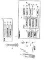
図1は、本発明の一実施形態に係る移動体通信システムの全体構成を示す図である。図1には、基地局3と自局の移動通信端末(以下、通信端末と称する)及び他局の通信端末の位置関係が示されている。ここでは、通信端末の受信状態により当該端末の送信パワーが制御される通信方式(例えば、CDMA2000 1xEV−DO方式)を用いた移動体通信システムを例にして、以下の説明においては、自局の通信端末1は、基地局3との間にビル等の障害物が介在し、低受信品質の通信状態にあり、他局の通信端末2は基地局3と高受信品質の通信状態にあるものとする。Hereinafter, an embodiment of the present invention will be described with reference to the drawings.
FIG. 1 is a diagram showing an overall configuration of a mobile communication system according to an embodiment of the present invention. FIG. 1 shows the positional relationship between a
図1に示す通信端末1、2は、無線LAN等のWiFiやWiMAX等の前記通信方式対比比較的近距離の通信方式の一つであるアドホック通信を使用して、アクセスポイントを介さずに通信端末同士が直接通信を行なうことができる通信機能を有している。
なお、図1中で通信端末は2つのみ例示しているが、これに限定されず、3つ以上であっても構わない。The
Although only two communication terminals are illustrated in FIG. 1, the present invention is not limited to this, and three or more communication terminals may be used.
ここで、本明細書及び特許請求の範囲において用いる用語について定義する。
自局及び他局は、通信端末が置かれている状態を示す論理的な名称であり、自局とは、相対的に低受信品質状態にある通信端末のことであり、他局とは相対的に高受信品質状態にある通信端末のことである。原則として、自局は他局に対して、下り通信情報の中継を依頼する通信端末であり、他局は自局からの中継依頼を受けて、基地局3からの下り通信情報を中継して自局へ送信する通信端末である。したがって、自局は少なくとも他局に対して中継を依頼する中継依頼手段を備えている必要があり、他局は少なくとも自局に対する下り通信情報の中継を行う中継実行手段を備えている必要がある。図1に示す例では、通信端末2が他局であり、通信端末1が自局となるが、2つの通信端末1、2が中継依頼手段と中継実行手段の両方を備えており、ビル等の障害物が基地局3と通信端末1との間ではなく、基地局3と通信端末2との間にある場合は、通信端末2が自局であり、通信端末1が他局となる場合もある。受信状態とは、通信端末における基地局からの受信信号の品質(搬送波対干渉波比;CIR)のことである。中継可能な温度とは、通信端末の動作温度から求めた、通信端末が中継局として動作可能な温度範囲のことである。通信情報とは、トラフィックデータのことである。送信要求とは、自局の識別情報(MACアドレス)と他局の通信速度を含み、基地局に対して、自局が他局を経由して、下りの通信情報の送信を要求するものである。Here, terms used in the present specification and claims are defined.
The local station and other stations are logical names indicating the state in which the communication terminal is placed. The local station is a communication terminal in a relatively low reception quality state and is relative to the other station. A communication terminal that is in a high reception quality state. In principle, the local station is a communication terminal that requests another station to relay downlink communication information, and the other station receives the relay request from the own station and relays the downlink communication information from the
次に、図2を参照して、図1に示す通信端末1及び基地局3の構成を説明する。図2は、図1に示す通信端末1及び基地局3の構成を示すブロック図である。なお、図1に示す通信端末2の構成は、通信端末1と同様な構成であるため、その詳細な説明を省略する。 Next, the configuration of the
図2の通信端末1において、基地局向け送受信部12は、通信端末1における基地局3に対する送受信処理を制御部21の制御によって実行する回路であり、この基地局向け送受信部12にアンテナ10が接続されている。また、無線LAN送受信部13は、他局の通信端末(ここでは、通信端末2)に対する無線LANによる送受信処理を制御部21の制御によって実行する回路であり、この無線LAN送受信部13にはアンテナ11が接続されている。 In the
制御部21は、基地局向け送受信部12、音声処理部14、画面表示部17及び操作キー18を制御して、音声通信における呼処理、電子メール等の送受信処理を行うとともに、無線LAN送受信部13における他局の通信端末との通信処理を制御する。また、制御部21は、温度測定部19を制御する。温度測定部19は、自通信端末1の筐体内部の温度を測定する。 The
制御部21は、本発明の機能を実現するための主要な機能部として、受信品質測定部22と、温度設定処理部23と、端末間情報交換部24と、通信端末選択部25等から構成されている。 The
受信品質測定部22は、基地局3からの下りパイロット信号を受信し受信品質(CIR)を測定する処理を行う。温度設定処理部23は、記憶部20に記憶されている温度データと温度測定部19により得られた温度データとから、警告温度上昇値を算出する。端末間情報交換部24は、受信可能な自局用の温度データと中継可能フラグを通信端末間で無線LANにより情報交換する処理を行う。通信端末選択部25は、自局の温度が警告温度上限値を超えた場合であって、且つ、他局の温度が中継可能温度上限値以下であった場合に、中継を依頼する相手となる他局の通信端末2を選択する処理を行う。 The reception
音声処理部14は音声信号の符号化・復号化処理を行う回路であり、マイク15及びスピーカ16に接続されている。記憶部20には、制御部21が実行するプログラムやデータ等が記憶されているともに、受信したデータの保存に用いる。 The
通信端末1の構成において、受信品質測定部22は自局の受信状態を測定する。また、温度設定処理部23は、記憶部20にある中継復帰温度設定値と中継可能温度上限値と警告温度上限値と停止温度上限値を取得し、温度測定部19により得られた温度データと上昇温度から警告温度上昇値を算出する。また、端末間情報交換部24は、自局宛の通信情報がなく、他局向けの通信情報を中継可能な場合には、自局の中継可能な温度を直接通信可能な周囲の通信端末に通知し、そうでない場合には、周囲の通信端末から中継可能な温度の情報を受信する。また、通信端末選択部25は、自局の温度が警告温度上限値を超えた場合であって、且つ、他局の温度が中継可能温度上限値以下であった場合に、他局の温度と中継可能温度上限値の差分値をそれぞれ比較し、その差分値の最も大きい中継可能な他局の通信端末2を決定する。但し、図1、2に示す例のように、他局の通信端末2が1台のみの場合は、他局の中継可能フラグを判定するのみである。 In the configuration of the
基地局3の制御部は、スケジューラ31と、自他局識別送信部32と、通信量補正部33等から構成されている。スケジューラ31は、プロポーショナルフェアー等の「過去の通信量の(所定時間あるいは所定アルゴリズムで求められた)平均に対する送信要求量(または要求速度)」に基づいて下りトラフィックデータ(通信情報)の送信順序および送信量等を決定する処理を行う。自他局識別送信部32は、自局の識別情報を含む送信要求を、他局の通信端末2から受信し、このヘッダ情報から中継を依頼した自局の通信端末1の識別情報を参照し、中継した他局の通信端末2を介して、中継を依頼した自局の通信端末1に下りトラフィックデータ(通信情報)を送信する処理を行う。 The control unit of the
通信量補正部33は、各通信端末への過去の通信量を算出する際に、中継した通信端末(他局の通信端末2)に対して送信した下りトラフィックデータの通信量について、中継を依頼した通信端末(自局の通信端末1)に対して送信したものとして取り扱う。具体的には、通信量補正部33は、中継を実施した他局の通信端末2の過去の通信量から上記通信量(中継を実施した通信量)を減算し、中継を依頼した自局の通信端末1の過去の通信量に対して上記通信量(他局が中継した通信量)を加算する処理を行う。 When calculating the past communication amount to each communication terminal, the communication
図3は、各局間の通信動作を示す図であり、以下、図3を参照して2つの通信端末1、2及び基地局3間の通信動作について説明する。ここでは、自局の通信端末1が基地局3から下りトラフィックデータを受信する必要がある状態であり、他局の通信端末2は、基地局3の通信エリア内に存在しているが、通信端末2自身は下りトラフィックデータを受信する必要はない状態にあるものとして説明する。 FIG. 3 is a diagram illustrating a communication operation between the stations. Hereinafter, a communication operation between the two
まず、通信端末1及び通信端末2は、電源オンの起動時に、温度測定部19の温度計測を開始する(ステップS1)。次いで、各種温度データの読み込みと温度設定を行う(ステップS2)。具体的には、中継復帰温度設定値と中継可能温度上限値と警告温度上限値と停止温度上限値を記憶部20から読み出す。また、温度測定部19により得られた温度データと上昇温度から警告温度上昇値を算出する。 First, the
次いで、通信端末1及び通信端末2は、それぞれ基地局3からの下りパイロット信号を受信して(ステップS3)、受信状態を測定し、受信可能な下り通信速度を算出するとともに送信パワーを設定する(ステップS4)。次いで、通信端末1及び通信端末2は、それぞれ基地局3にDRCを返し(ステップS5)、基地局3からのパワービットを受信して(ステップS6)、基地局3により送信パワーを制御される(送信パワーのクローズループ動作)(ステップS7)。 Next, each of the
次いで、通信端末1と通信端末2は原則として、相互に、中継可能フラグを交換するが、ここでは、通信端末1は、中継可能な状態ではないため、通信端末2に対して自局の中継可能フラグを送信せず、通信端末2から他局の中継可能フラグを受信するのみである(ステップS8)。通信端末1において「中継可能温度上限値T1>警告温度上限値T2」と判定した場合は、通信端末1から通信端末2に対して中継依頼を行なう(ステップS9)。 Next, in principle, the
次いで、通信端末2は、通信端末1からの中継依頼を受けた場合に、基地局3に対して中継情報を付加した下りトラフィック要求(送信要求)を送信する(ステップS10)。基地局3は、通信端末2に対して、「自局の通信端末1向けの下りトラフィックデータ」を送信する(ステップS11)。これを受けて、通信端末2は、基地局3から受信した「通信端末1向けの下りトラフィックデータ」を無線LANにより中継して通信端末1へ送信する(ステップS12)。 Next, when receiving a relay request from the
なお、受信可能な下り通信情報の送信を自局の通信端末1が中継可能な状態にある場合に行うようにしたのは、他局の通信端末2から中継を依頼されないようにするためである。尤も自局の通信端末1と直接通信可能な他局の通信端末2が存在する場合でも中継可能な通信端末が無い場合は自局の通信端末1は基地局3と直接通信することとなる。 The reason why transmission of receivable downlink communication information is performed when the
このようして、本発明の移動体通信システムおよび通信端末においては、自局の通信端末1の筐体内部の温度上昇によるオーバヒート状態となる前に他局の通信端末2を中継局とすることにより、自局の通信端末1のオーバヒートを回避することができ、ユーザの利便性を高めることができる。 Thus, in the mobile communication system and the communication terminal of the present invention, the
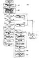
次に、図4を参照して、通信端末1の内部処理動作の詳細について説明する。図4は、通信端末1の動作を示すフローチャートである。図4に示すフローチャートは、通信端末1が中継依頼手段と中継実行手段の両方を備えている場合の処理動作を示している。
図4において、先ず、通信端末1は温度設定処理を開始する(ステップS21)。この温度設定処理については後述する。次いで、スロットnの処理が開始される(ステップS22)。通信端末1では、基地局3からの下りパイロット信号により、受信状態を測定し(ステップS23)、送信パワーを設定する(ステップS24)。Next, details of the internal processing operation of the
In FIG. 4, first, the
次いで、通信端末1は、無線LANにより直接通信可能な他局の通信端末2があるか否かを判定する(ステップS25)。ステップS25において無線LANにより直接通信可能な他局の通信端末2がないと判定した場合は、基地局3へ自局の受信可能な下り通信情報を含めて送信し、下りトラフィックデータ(自局宛の通信情報)の送信を要求する(ステップS26)。そして、下りトラフィックデータがアサインされた場合は、基地局3から下りトラフィックデータを受信し(ステップS27、S28)、下りトラフィックデータがアサインされなかった場合は、最初のステップS21に戻る。 Next, the
一方、ステップS25において、無線LANにより直接通信可能な他局の通信端末2があると判定された場合は、通信端末1(自局)は中継可能か否かを判定する(ステップS29)。ステップS29において、自局は中継可能でないと判定した場合は、ステップS30に移行し、中継可能な通信端末2があるか否かを判定し、中継可能な通信端末2がない場合は、ステップS26に移行し、自局で下りトラフィックデータを受信する処理を行う。ステップS30において、中継可能な通信端末2があると判定した場合には、無線LAN上で中継可能な通信端末2から受信可能な中継可能フラグを受信する(ステップS31)。 On the other hand, if it is determined in step S25 that there is a
次いで、通信端末1は自局で通信を継続することの可否を中継依頼フラグから判断し(ステップS32)、中継依頼フラグがない場合(自局で通信を継続可能な場合)にはステップS26に移行し、自局で下りトラフィックデータを受信する処理を行う。ステップS32において、中継依頼フラグがある場合(自局で通信を継続可能でない場合)には、無線LAN上で、最も低い測定温度Tの通信端末(ここでは通信端末2)へ中継を依頼する(ステップS33)。そして、無線LAN上に下りトラフィックデータがある場合において、データ残量(警告温度上昇値)が警告温度上限値を超えるときは、無線LAN上で下りトラフィックデータを受信する(ステップS34、S35、S36)。無線LAN上に下りトラフィックデータがない場合、及び、データ残量(警告温度上昇値)が警告温度上限値を超えない場合には、ステップS26に移行し、自局で下りトラフィックデータを受信する処理を行う。なお、警告温度上昇値については後述する。 Next, the
一方、ステップS29において、自局は中継可能と判定した場合は、ステップS37に移行し、無線LAN上で受信可能な中継可能フラグを送信する。そして、他局の通信端末n(中継依頼している他局)からの中継依頼があるか否かを判定し(ステップS38)、中継依頼がない場合は、ステップS26に移行する。中継依頼がある場合には、通信端末nの中継情報を付加して基地局3に送信する(ステップS39)。 On the other hand, if it is determined in step S29 that the local station can relay, the process proceeds to step S37, and a relayable flag that can be received on the wireless LAN is transmitted. Then, it is determined whether or not there is a relay request from the communication terminal n of the other station (the other station that has requested relay) (step S38). If there is no relay request, the process proceeds to step S26. If there is a relay request, the relay information of the communication terminal n is added and transmitted to the base station 3 (step S39).
次いで、通信端末1は、下りトラフィックデータがアサインされたか否かを判定し(ステップS40)、下りトラフィックデータがアサインされた場合は、下りトラフィックデータを受信し(ステップS41)、受信した下りトラフィックデータを無線LAN上で通信端末nに送信する(ステップS42)。一方、ステップS40において、下りトラフィックデータがアサインされていないと判定した場合は、最初のステップS21に戻る。 Next, the
以上の処理動作により、直接通信可能な範囲に存在する複数の通信端末の中で最も筐体内部温度の低い通信端末を中継局として通信することができ、自局及び中継局のオーバーヒートを回避しつつ、通信を継続することが可能になる。これにより、ユーザの利便性を高めることができる。 With the above processing operation, a communication terminal with the lowest internal temperature of the casing can be communicated as a relay station among a plurality of communication terminals existing in a directly communicable range, and overheating of the own station and the relay station is avoided. However, communication can be continued. Thereby, a user's convenience can be improved.
なお、通信端末1が通信端末2に対して中継を依頼する場合は、通信端末1は通信端末2に対し、無線LANを用いて自局宛の下りトラフィックデータの中継を依頼し、他局の通信端末2はこの依頼に応じて基地局3に送信要求する。 When the
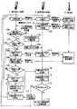
次に、図5を参照して、上記図4のステップS21における温度設定処理動作の詳細について説明する。図5は、通信端末1の温度設定処理動作を示すフローチャートである。
図5において、先ず、通信端末1は、自筐体内部の温度を測定し、測定温度Tを得る(ステップS51)。次いで、予め通信端末1のデータとして記憶部20に記憶されている、中継復帰温度設定値T0、中継可能温度上限値T1、警告温度上限値T2及び停止温度上限値T3を記憶部20から読み出す(ステップS52)。Next, with reference to FIG. 5, the details of the temperature setting processing operation in step S21 of FIG. 4 will be described. FIG. 5 is a flowchart showing the temperature setting processing operation of the
In FIG. 5, first, the
次いで、通信端末1は、測定温度Tと中継復帰温度設定値T0を比較し(ステップS53)、「測定温度T<中継復帰温度設定値T0」の場合には、自局は中継することが可能な端末であると判断し、ステップS54に移行する。ステップS54では、測定温度Tと停止温度上限値T3を比較し、「測定温度T<停止温度上限値T3」の場合には、自局はオーバーヒート状態ではないと判断し、ステップS55に移行する。ステップS55では、測定温度Tと警告温度上限値T2を比較し、「測定温度T<警告温度上限値T2」の場合には、自局は中継を必要としないと判断し、ステップS56に移行する。ステップS56では、測定温度Tと中継可能温度上限値T1を比較し、「測定温度T<中継可能温度上限値T1」の場合には、自局は中継可能であると判断し、ステップS57に移行する。ステップS57では中継可能フラグを設定し、その時の測定温度Tを上昇温度として記憶部20に記憶する(ステップS58)。ここから上昇温度の測定が開始される。次いで、通信端末1は、中継可能温度上限値T1の値に中継可能温度上限値の初期値を代入し(ステップS59)、測定温度Tの監視を継続する(ステップS60)。そして、ステップS56に移行する。 Next, the
一方、通信端末1は、ステップS53において「測定温度T<中継復帰温度設定値T0」ではない場合には、自局は中継することができない端末であるので、中継禁止フラグを設定し(ステップS61)、ステップS53に移行する。そのステップS61の中継禁止フラグ設定処理は、環境温度によって初期起動時から中継が不可能な筐体内部温度であった場合に有効な処理である。 On the other hand, if “measured temperature T <relay return temperature set value T0” is not satisfied in step S53,
また、通信端末1は、ステップS54において「測定温度T<停止温度上限値T3」ではない場合には、自装置の動作を停止する(ステップS68)。また、ステップS55において「測定温度T<警告温度上限値T2」ではない場合には、自局は中継を必要とするので、中継依頼フラグを設定し(ステップS62)、ステップS53に移行する。 In addition, when “measured temperature T <stop temperature upper limit T3” is not satisfied in step S54, the
また、通信端末1は、ステップS56において「測定温度T<中継可能温度上限値T1」ではない場合には、自局は中継不可能であるので、自局が他局を中継しているかを確認し(ステップS63)、他局を中継している場合には、他局への下り通信情報切断許可フラグを送信する(ステップS64)。次いで、切断処理を行い(ステップS70)、中継している他局からの切断フラグを受信する(ステップS71)。そして、ステップS65に移行する。一方、ステップS63において、自局が他局を中継していない場合には、そのままステップS65に移行する。 In addition, if “measured temperature T <relayable temperature upper limit value T1” is not satisfied in step S56, the
ステップS65では、通信端末1は、中継可能フラグを停止する。次いで、通信端末1は、自筐体内部温度を中継可能な温度まで下げるために、中継可能温度上限値T1の値に中継復帰温度設定値T0を代入する(ステップS66)。次いで、通信端末1は、ステップS58で開始した上昇温度の測定を停止し、この時の測定温度Tを警告温度上限値T2に設定する(ステップS67)。そして、ステップS55に移行する。 In step S65, the
次に、図6を参照して、警告温度上昇値について説明する。図6は、警告温度上昇値について説明するためのグラフ図である。
図6のグラフ図において、縦軸は温度を示し、横軸は転送レートを示す。波形G1は通信端末の筐体内部の温度上昇カーブの一例を示しているが、通信端末の環境温度によってその温度上昇カーブは変化する。上昇温度測定開始値G2は、上記図5のステップS58で測定を開始した上昇温度の開始点を示し、上昇温度測定停止値G3は、上記図5のステップS67で測定を停止した上昇温度の終了点を示している。Next, the warning temperature increase value will be described with reference to FIG. FIG. 6 is a graph for explaining the warning temperature rise value.
In the graph of FIG. 6, the vertical axis indicates the temperature, and the horizontal axis indicates the transfer rate. Although the waveform G1 shows an example of the temperature rise curve inside the housing of the communication terminal, the temperature rise curve changes depending on the environmental temperature of the communication terminal. The rising temperature measurement start value G2 indicates the starting point of the rising temperature at which measurement was started in step S58 in FIG. 5, and the rising temperature measurement stop value G3 is the end of the rising temperature at which measurement was stopped in step S67 in FIG. Shows the point.
そして、(1)式に示されるように、温度上昇カーブから温度単位あたりのビットレートを算出し、この算出値を警告温度上昇係数とする。警告温度上昇値Tuは、その警告温度上昇係数でデータ残量を除算し、この除算結果に測定温度Tを加算した値である((2)式参照)。これにより、データ残量に対する警告温度上昇値Tuが求まる。上記図4のステップS35では、その警告温度上昇値Tuと警告温度上限値T2を比較する。 Then, as shown in the equation (1), a bit rate per temperature unit is calculated from the temperature increase curve, and this calculated value is used as a warning temperature increase coefficient. The warning temperature rise value Tu is a value obtained by dividing the remaining amount of data by the warning temperature rise coefficient and adding the measured temperature T to the division result (see equation (2)). Thereby, the warning temperature rise value Tu for the remaining amount of data is obtained. In step S35 of FIG. 4, the warning temperature increase value Tu is compared with the warning temperature upper limit value T2.
次に、図7を参照して、上記図5のステップS70における切断処理動作の詳細について説明する。図7は、図1に示す移動体通信システムにおける切断処理動作を示すフローチャートである。図7の例では、通信端末1(自局)が通信端末2(他局)を介して基地局3と通信している。 Next, the details of the cutting processing operation in step S70 of FIG. 5 will be described with reference to FIG. FIG. 7 is a flowchart showing a disconnection processing operation in the mobile communication system shown in FIG. In the example of FIG. 7, the communication terminal 1 (own station) communicates with the
図7において、通信端末2は、ステップS101の通信端末1からの中継依頼により、基地局3からの通信端末1のデータを通信端末1へ中継している(ステップS102)。ここで、通信端末2は、自筐体内部の温度が上昇し中継可能な温度を超えると、中継中であるので、下り通信情報切断フラグを送信する(ステップS103)。 In FIG. 7, the
次いで、通信端末1は、その下り通信情報切断フラグを受信すると、自局が基地局3と直接通信することが可能か判断する(ステップS104)。次いで、通信端末1は、ステップS104で自局が基地局3と直接通信することができないと判断した場合には、次の他局の通信端末に対して中継依頼を行う(ステップS105)。そして、切断フラグを通信端末2へ送信する(ステップS106)。 Next, when receiving the downlink communication information disconnect flag, the
一方、通信端末1は、ステップS104で自局が基地局3と直接通信することができると判断した場合には、自局が中継可能か判断する(ステップS107)。次いで、通信端末1は、ステップS107で自局が中継することはできないと判断した場合には、切断フラグを通信端末2へ送信し(ステップS108)、基地局3と直接通信を開始する(ステップS109)。次いで、通信端末1は、自局が中継可能か判断し(ステップS110)、中継できないならばステップS108に移行し、以降は、自局が中継可能になるまで、ステップS108、S109を繰り返す。そして、中継可能になったときに、ステップS113に移行する。 On the other hand, if it is determined in step S104 that the local station can directly communicate with the
通信端末2は、切断フラグを受信すると、中継可能フラグを停止する(ステップS111)。但し、基地局3との通信は継続する。 When receiving the disconnection flag, the
通信端末1は、ステップS107で自局が中継可能であると判断した場合には、切断フラグを通信端末2へ送信する(ステップS112)。次いで、ステップS113では、通信端末1は、中継可能フラグと中継予約フラグを通信端末2へ送信する。 If it is determined in step S107 that the local station can relay, the
通信端末2は、中継予約フラグを受信すると(ステップS114)、次の中継依頼フラグの設定を行う場合に(ステップS115)、予約の有無を確認する(ステップS116)。その確認の結果、予約があった場合には、予約局(ここでは、通信端末1)へ中継依頼を行う(ステップS117)。通信端末1は、その中継依頼フラグを受信すると(ステップS118)、今度は他局として中継を行う(ステップS102)。一方、他局であった通信端末2は、今度は自局として中継してもらう側になる(ステップS101)。 When the
一方、ステップS116で予約がなかった場合には、通信端末2は、次に低い測定温度Tの通信端末に中継を依頼する(ステップS119)。 On the other hand, if there is no reservation in step S116, the
図8は、MACアドレスを付加した拡張DRCフレームの例を示す図である。
MACアドレスとは、EV−DO方式において基地局3と通信している各通信端末を識別するアドレス(コード)である。通信情報中のヘッダ情報としては中継を要求する通信端末1のMACアドレス(6bit)を含み、通信端末2から基地局3へは上りトラフィックデータチャネル上で、DRCサブチャネルにDRCシンボルの4bitを拡張して送信する。また、DRCサブチャネルの一部をパンクチャリングしてMACアドレス情報を載せる。また、パイロットサブチャネルの一部をパンクチャリングしてMACアドレス情報を載せる等の方法を用いることもできる。FIG. 8 is a diagram illustrating an example of an extended DRC frame to which a MAC address is added.
The MAC address is an address (code) that identifies each communication terminal communicating with the
なお、本実施形態においては、基地局3はスケジューリングに基づき、通信端末宛の下りトラフィックデータを送出する場合には、下りトラフィックデータに通信端末宛であることを示すヘッダを付加してもよいし、通信端末は受信する下りトラフィックデータに対応する下りデータ要求が通信端末の要求であることを知っているためヘッダを付加しないことによりトラフィックデータのオーバーヘッド増加を避けるようにしても良い。 In the present embodiment, the
各通信端末は基地局3から受信した下りトラフィックデータを通信端末に無線LANを用いて送出し、通信端末は無線LAN上で下りトラフィックデータを受信することができる。この場合、基地局3はスケジューリングを行うが、スケジューリングは以下に説明するプロポーショナルフェアーアルゴリズムに基づいて行われる。 Each communication terminal transmits the downlink traffic data received from the
基地局3と通信している全ての通信端末に対し、基地局3は直近の割り当て通信速度の平均Ri(n)を記憶し、所定の送信タイミング(1/600秒毎)で更新を行う。
Ri(n)=(1−1/tc)×Ri(n−1)+1/tc×ri(n−1)
ここで、
Ri(n):通信端末iに対するスロットnにおける平均データ通信速度、
ri(n):通信端末iに対するスロットnにおける伝送データ通信速度であり、通信端末iに対する下りトラフィックがアサインされない場合は0、
tc(i):時定数For all communication terminals communicating with the
Ri (n) = (1-1 / tc) × Ri (n−1) + 1 / tc × ri (n−1)
here,
Ri (n): average data communication speed in slot n for communication terminal i,
ri (n): transmission data communication speed in slot n for communication terminal i, 0 if downlink traffic for communication terminal i is not assigned,
tc (i): Time constant
基地局3は通信端末iの時刻nにおける以下の評価関数を求める。
Fi(n)=DRCi(n)/Ri(n)
DRCi(n):通信端末iのスロットnにおける要求データ通信速度、通信端末が求め基地局に送信する受信可能な下り通信速度The
Fi (n) = DRCi (n) / Ri (n)
DRCi (n): requested data communication speed in slot n of communication terminal i, receivable downlink communication speed that the communication terminal obtains and transmits to the base station
基地局3は各送信タイミング(1/600秒毎)で各通信端末のFi(n)を評価し、Fi(n)が最大である通信端末に下りトラフィックデータをアサインする。 The
上記評価式計算過程において、通信端末i(通信端末1)が基地局3と直接通信した場合はri(n)を実際に伝送された通信速度とするが、通信端末iが通信端末j(通信端末2)を中継局として通信し、基地局3からの下りトラフィックが実際には通信端末jにアサインされた場合、(従来技術であればri(n)=0、rj(n)は実際に伝送された通信速度となる)rj(n)=0、ri(n)を通信端末jに対して実際に伝送された通信速度とする。 When the communication terminal i (communication terminal 1) directly communicates with the
またはri(n)=0、rj(n)は通信端末jに実際に伝送された通信速度として
Ri(n)=(1−1/tc)×Ri(n−1)+1/tc×rj(n−1)、
Rj(n)=(1−1/tc)×Rj(n−1)+1/tc×rj(n−1)、とする。Alternatively, ri (n) = 0, and rj (n) is the transmission speed actually transmitted to the communication terminal j. Ri (n) = (1-1 / tc) × Ri (n−1) + 1 / tc × rj ( n-1),
Rj (n) = (1-1 / tc) × Rj (n−1) + 1 / tc × rj (n−1).
また、Ri(n)の計算に以下のような補正を加える。
n−1の時点で通信端末iが通信端末jを中継局として基地局と通信し、基地局3から下りトラフィックが通信端末jにアサインされた時、
Ri(n)=(1−1/tc)×Ri(n−1)+1/tc×rj(n−1)×(1+c)、
Rj(n)=(1−1/tc)×Rj(n−1)+1/tc×rj(n−1)×(−c)、
c:補正係数、0.1〜0.5程度とする。Further, the following correction is added to the calculation of Ri (n).
When the communication terminal i communicates with the base station using the communication terminal j as a relay station at the time point n-1, and when downlink traffic is assigned to the communication terminal j from the
Ri (n) = (1-1 / tc) × Ri (n−1) + 1 / tc × rj (n−1) × (1 + c),
Rj (n) = (1-1 / tc) × Rj (n−1) + 1 / tc × rj (n−1) × (−c),
c: Correction coefficient, about 0.1 to 0.5.
すなわち、通信端末jに中継してもらった通信端末iの平均データ速度は補正係数cだけ割増、通信端末2の平均データ速度はcだけ割引となり、以後の評価関数計算で通信端末2の方が通信端末1より有利になる。同様の補正計算は評価関数に対しオフセット(通信端末iのFi(n)を減らし、通信端末jのFj(n)を増やす)するなどの方法も可能である。 That is, the average data rate of the communication terminal i relayed by the communication terminal j is increased by the correction coefficient c, and the average data rate of the
以上説明したスケジューリング方法により、中継を行う通信端末がスケジューリング上不利な扱いを受けることがなく、さらに、電力消費等の不利益をスケジューリング上で補償する仕組みを導入することができる。 With the scheduling method described above, it is possible to introduce a mechanism that compensates for disadvantages such as power consumption in scheduling without causing communication terminals that perform relaying to be disadvantageous in scheduling.
なお、下り通信情報(トラフィックデータ)の中継を依頼する通信端末(図1においては、自局の通信端末1)は、周囲の通信端末に対して、下り通信情報(トラフィックデータ)の中継を実行する中継実行手段を必ずしも備えていなくてもよい。また、下り通信情報(トラフィックデータ)の中継を実行する通信端末(図1においては、他局の通信端末2)は、周囲の通信端末に対して、下り通信情報(トラフィックデータ)の中継を依頼するする中継依頼手段を必ずしも備えていなくてもよい。 Note that a communication terminal (in FIG. 1, the
以上、本発明の実施の形態を通信端末(移動通信端末)を例にして説明したが、この通信端末としては、携帯電話機、モバイル端末、PDA(Personal Digital Assistance)等が含まれる。 Although the embodiments of the present invention have been described by taking the communication terminal (mobile communication terminal) as an example, the communication terminal includes a mobile phone, a mobile terminal, a PDA (Personal Digital Assistance), and the like.
本発明においては、自局がオーバーヒートとなる前に、直接通信可能な範囲にいる複数通信端末の中で最も筐体内部温度が低い通信端末を中継局とすることにより、オーバーヒートを回避してデータを受信することができ、ユーザの利便性を高めることができる。このため、本発明は、移動体通信システム、および通信端末等に有用である。 In the present invention, before the own station is overheated, the communication terminal having the lowest internal temperature of the casing among the plurality of communication terminals in the range capable of direct communication is used as a relay station, thereby avoiding overheating and data. Can be received, and the convenience of the user can be improved. Therefore, the present invention is useful for mobile communication systems, communication terminals, and the like.
1、2…通信端末(移動通信端末)、3…基地局、10,11…アンテナ、12…基地局向け送受信部(第1無線通信手段)、13…無線LAN送受信部(第2無線通信手段)、14…音声処理部、15…マイク、16…スピーカ、17…画面表示部、18…操作キー、19…温度測定部、20…記憶部、21…制御部、22…受信品質測定部、23…温度設定処理部、24…端末間情報交換部、25…通信端末選択部、31…スケジューラ、32…自他局識別送信部、33…通信量補正部
DESCRIPTION OF
Claims (4)
Translated fromJapanese温度測定手段と、
データを送信する際に上昇する温度を算出する手段と、
前記算出した上昇温度に前記温度測定手段が測定した測定温度を加算した温度上昇値に応じて、前記第1無線通信手段又は前記第2無線通信手段のいずれかに選択的に切り替える制御手段と、
を備えたことを特徴とする通信端末。In a communication terminal comprising a first wireless communication means for communicating with a base station and a second wireless communication means for communicating with another terminal having the first wireless communication means,
Temperature measuring means;
Means for calculating the temperature rising when sending data;
Control means for selectively switching to either the first wireless communication means or the second wireless communication means accordingto a temperature rise value obtained by adding the measured temperature measured by the temperature measurement meansto the calculated rise temperature ;
A communication terminal comprising:
前記通信端末は、
温度測定手段と、
データを送信する際に上昇する温度を算出する手段と、
前記算出した上昇温度に前記温度測定手段が測定した測定温度を加算した温度上昇値に応じて、前記第1無線通信手段又は前記第2無線通信手段のいずれかに選択的に切り替える制御手段と、を有し、
前記第2無線通信手段を用いて、前記基地局と他端末の通信を中継する、
ことを特徴とする移動体通信システム。A mobile communication system comprising a base station and a communication terminal having a first wireless communication means for communicating with the base station and a second wireless communication means for communicating with another terminal having the first wireless communication means In
The communication terminal is
Temperature measuring means;
Means for calculating the temperature rising when sending data;
Control means for selectively switching to either the first wireless communication means or the second wireless communication means accordingto a temperature rise value obtained by adding the measured temperature measured by the temperature measurement meansto the calculated rise temperature; Have
Relaying communication between the base station and other terminals using the second wireless communication means;
A mobile communication system.
前記通信端末の温度を測定する温度測定過程と、
データを送信する際に上昇する温度を算出する過程と、
前記算出した上昇温度に前記測定した測定温度を加算した温度上昇値に応じて、前記各通信のいずれかに選択的に切り替える制御過程と、
を含むことを特徴とする通信制御方法。A communication control method for controlling communication between a base station and a communication terminal, and communication between the communication terminals,
A temperature measurement process for measuring the temperature of the communication terminal;
Calculating the temperature that rises when sending data;
In accordancewith a temperature rise value obtained by adding the measured temperatureto thecalculated rise temperature, a control process for selectively switching to any one of the communications,
The communication control method characterized by including.
Priority Applications (4)
| Application Number | Priority Date | Filing Date | Title |
|---|---|---|---|
| JP2005285231AJP4624227B2 (en) | 2005-09-29 | 2005-09-29 | Communication terminal, mobile communication system, and communication control method |
| KR1020060094401AKR100809154B1 (en) | 2005-09-29 | 2006-09-27 | Communication terminal, mobile communication system, and communication control method |
| US11/535,886US8494512B2 (en) | 2005-09-29 | 2006-09-27 | Communication terminal, mobile communication system, and communication control method |
| CNA2006101399334ACN1941646A (en) | 2005-09-29 | 2006-09-27 | Communication terminal and mobile communication system and communication control method |
Applications Claiming Priority (1)
| Application Number | Priority Date | Filing Date | Title |
|---|---|---|---|
| JP2005285231AJP4624227B2 (en) | 2005-09-29 | 2005-09-29 | Communication terminal, mobile communication system, and communication control method |
Publications (2)
| Publication Number | Publication Date |
|---|---|
| JP2007096925A JP2007096925A (en) | 2007-04-12 |
| JP4624227B2true JP4624227B2 (en) | 2011-02-02 |
Family
ID=37959486
Family Applications (1)
| Application Number | Title | Priority Date | Filing Date |
|---|---|---|---|
| JP2005285231AExpired - Fee RelatedJP4624227B2 (en) | 2005-09-29 | 2005-09-29 | Communication terminal, mobile communication system, and communication control method |
Country Status (4)
| Country | Link |
|---|---|
| US (1) | US8494512B2 (en) |
| JP (1) | JP4624227B2 (en) |
| KR (1) | KR100809154B1 (en) |
| CN (1) | CN1941646A (en) |
Families Citing this family (19)
| Publication number | Priority date | Publication date | Assignee | Title |
|---|---|---|---|---|
| US8223625B2 (en)* | 2006-08-23 | 2012-07-17 | Qualcomm, Incorporated | Acquisition in frequency division multiple access systems |
| CN101529951B (en) | 2006-10-27 | 2012-12-12 | 捷讯研究有限公司 | Link quality measurements based on data rate and received power level |
| CN101296016A (en)* | 2007-04-27 | 2008-10-29 | 北京三星通信技术研究有限公司 | Transmission Method of Multicast Data in WiMax&WiBro Relay System |
| JP5281312B2 (en)* | 2008-04-25 | 2013-09-04 | キヤノン株式会社 | COMMUNICATION DEVICE, ITS CONTROL METHOD, COMPUTER PROGRAM |
| WO2010006649A1 (en)* | 2008-07-17 | 2010-01-21 | Nokia Siemens Networks Oy | Device-to-device communications in cellular system |
| US8711774B2 (en)* | 2008-07-30 | 2014-04-29 | Hitachi, Ltd. | Wireless communication system and wireless communication method |
| CN102119490B (en)* | 2008-08-06 | 2015-04-15 | 联想创新有限公司(香港) | Wireless communication apparatus, wireless communication method, and wireless communication system |
| WO2012118311A2 (en)* | 2011-03-01 | 2012-09-07 | Lg Electronics Inc. | Method of transmitting and receiving data in a wireless communication system and apparatus therefor |
| US8675615B2 (en) | 2011-05-03 | 2014-03-18 | Qualcomm Incorporated | Temperature-driven airlink selection in a multi-mode wireless device |
| CN103049018B (en)* | 2012-12-26 | 2015-07-08 | 华为终端有限公司 | Overheat protection method and device for handheld electronic equipment and handheld electronic equipment |
| CN103118442A (en)* | 2013-01-24 | 2013-05-22 | 浪潮电子信息产业股份有限公司 | Handheld type terminal with base station relay function |
| US9055470B2 (en)* | 2013-03-01 | 2015-06-09 | Qualcomm Incorporated | Method and apparatus for utilizing the smart blanking feature of thermal mitigation |
| CN113055941B (en)* | 2015-03-12 | 2023-04-14 | 荣耀终端有限公司 | Data transmission method, device, processor and mobile terminal |
| US10880304B2 (en)* | 2016-04-06 | 2020-12-29 | Qualcomm Incorporated | Network verification of wearable devices |
| KR102330254B1 (en)* | 2017-04-07 | 2021-11-23 | 삼성전자주식회사 | Method for controlling of traffic and an electronic device thereof |
| US10419077B1 (en)* | 2018-03-28 | 2019-09-17 | Google Llc | Wireless communication via a mobile relay |
| WO2020245960A1 (en)* | 2019-06-05 | 2020-12-10 | 本田技研工業株式会社 | Wireless base station, communication system, program, control method, and wireless communication device |
| JP7038442B2 (en)* | 2021-01-12 | 2022-03-18 | 株式会社ユピテル | Relay system, repeater and program |
| JP7171952B1 (en)* | 2022-02-16 | 2022-11-15 | 株式会社フジクラ | Wireless communication module output adjustment method, wireless communication module manufacturing method, and wireless communication module output adjustment device |
Family Cites Families (26)
| Publication number | Priority date | Publication date | Assignee | Title |
|---|---|---|---|---|
| US31990A (en)* | 1861-04-09 | Alexander millar | ||
| US133722A (en)* | 1872-12-10 | Improvement in plows | ||
| JPS63226124A (en)* | 1986-10-29 | 1988-09-20 | Oki Electric Ind Co Ltd | Level control circuit for radio equipment |
| JPH07264114A (en) | 1994-03-23 | 1995-10-13 | Oki Electric Ind Co Ltd | Radio terminal equipment relay system and radio terminal equipment |
| JP2990150B2 (en) | 1998-04-06 | 1999-12-13 | 静岡日本電気株式会社 | Method and apparatus for preventing overheating of mobile phone |
| JP3223887B2 (en) | 1998-09-07 | 2001-10-29 | 株式会社デンソー | Wireless communication device |
| US6760311B1 (en) | 1998-11-20 | 2004-07-06 | Ericsson Inc. | Thermal transmission control of wireless data modem |
| JPH11243362A (en) | 1998-12-25 | 1999-09-07 | Matsushita Electric Ind Co Ltd | Wireless telephone device, wireless telephone relay device, and wireless telephone system |
| GB2355367A (en)* | 1999-10-13 | 2001-04-18 | Ericsson Telefon Ab L M | Adjusting allocation of transmission slots according operating conditions in a mobile telephone |
| WO2001033722A1 (en)* | 1999-11-05 | 2001-05-10 | Sony Corporation | Method and device for data transmission |
| US6504484B1 (en)* | 2000-09-26 | 2003-01-07 | Cohand Technology Co., Ltd. | Control method using power to prevent overheat inside of electric equipment |
| KR20020025476A (en)* | 2000-09-29 | 2002-04-04 | 윤종용 | Apparatus and method for modifying service class with respect to generation of heat in a gprs terminal |
| JP3731469B2 (en) | 2000-12-04 | 2006-01-05 | Kddi株式会社 | Wireless packet communication system and base station |
| US7200512B2 (en)* | 2001-02-16 | 2007-04-03 | Sierra Wireless, Inc. | Method for avoiding peak temperatures in communication devices |
| JP2003309512A (en) | 2002-04-16 | 2003-10-31 | Denso Corp | Radio communication terminal |
| US8169981B2 (en)* | 2002-10-31 | 2012-05-01 | Motorola Mobility, Inc. | Method and mobile station for controlling communication via a radio link |
| BR0215939A (en)* | 2002-11-29 | 2005-09-06 | Yamaha Corp | Magnetic sensor and method for characteristically temperature dependent compensation of magnetic sensor |
| JP4110522B2 (en)* | 2002-12-13 | 2008-07-02 | ソニー株式会社 | Wireless communication apparatus and communication control method |
| US20040194237A1 (en)* | 2003-04-04 | 2004-10-07 | Walton Charles A. | Underwater cleaning apparatus using suction grip |
| CN1771664B (en)* | 2003-04-11 | 2011-09-28 | Nxp股份有限公司 | Device for detecting the temperature of an oscillator crystal |
| JP4049013B2 (en)* | 2003-05-08 | 2008-02-20 | Kddi株式会社 | Wireless multi-hop network access control method, relay terminal, and mobile terminal |
| JP2005065136A (en) | 2003-08-20 | 2005-03-10 | Fuji Photo Film Co Ltd | Data transmitting apparatus |
| US7206567B2 (en)* | 2003-11-10 | 2007-04-17 | Research In Motion Limited | Methods and apparatus for limiting communication capabilities in mobile communication devices |
| JP4363205B2 (en)* | 2004-02-05 | 2009-11-11 | 株式会社日立製作所 | Mobile terminal device |
| KR20070025325A (en)* | 2005-09-01 | 2007-03-08 | 엘지전자 주식회사 | Handoff Device and Method of Mobile Communication Terminal |
| JP4778318B2 (en)* | 2006-01-20 | 2011-09-21 | 富士通東芝モバイルコミュニケーションズ株式会社 | Mobile device |
- 2005
- 2005-09-29JPJP2005285231Apatent/JP4624227B2/ennot_activeExpired - Fee Related
- 2006
- 2006-09-27KRKR1020060094401Apatent/KR100809154B1/ennot_activeExpired - Fee Related
- 2006-09-27USUS11/535,886patent/US8494512B2/ennot_activeExpired - Fee Related
- 2006-09-27CNCNA2006101399334Apatent/CN1941646A/enactivePending
Also Published As
| Publication number | Publication date |
|---|---|
| US8494512B2 (en) | 2013-07-23 |
| KR20070036687A (en) | 2007-04-03 |
| US20070142058A1 (en) | 2007-06-21 |
| KR100809154B1 (en) | 2008-02-29 |
| CN1941646A (en) | 2007-04-04 |
| JP2007096925A (en) | 2007-04-12 |
Similar Documents
| Publication | Publication Date | Title |
|---|---|---|
| JP4624227B2 (en) | Communication terminal, mobile communication system, and communication control method | |
| JP4791604B2 (en) | Transmission control by temperature in wireless data modem | |
| TWI389513B (en) | Cell network selectively applying proxy mode to minimize power | |
| KR100582727B1 (en) | Wireless LAN transmission power control system and method | |
| KR101287683B1 (en) | Terminal transmit power control with link adaptation | |
| KR100603561B1 (en) | Wireless LAN system based on transmission power control and transmission power control method thereof | |
| US9414424B2 (en) | Method and arrangement for adjusting signal-to-interference-plus-noise-ratio in a device-to-device communication | |
| CN103119995B (en) | Radio communication device, wireless communications method and treatment circuit | |
| KR102542922B1 (en) | Information processing device and information processing method | |
| US20130295989A1 (en) | Co-existence Aware Rate Support | |
| US9807803B2 (en) | Transmission control for wireless communication networks | |
| TW200838202A (en) | Inter-cell power control for interference management | |
| KR20050041227A (en) | Method of power control using per in wpan system | |
| WO2009122518A1 (en) | Receiving device, transmitting device, receiving method, and transmitting method | |
| JP7488839B2 (en) | COMMUNICATION METHOD, TERMINAL DEVICE, AND NETWORK DEVICE | |
| JP4791378B2 (en) | Communication terminal and mobile communication system provided with the same | |
| JP4000122B2 (en) | Wireless communication system and wireless communication method | |
| JP2004282756A (en) | Power control method of wireless connection node in wireless LAN system | |
| EP1214854A1 (en) | Temperature controlled radio transmitter in a tdma system | |
| KR101087671B1 (en) | Method and system for performing periodic ranging by dynamically setting ranging interval according to propagation environment in portable internet network | |
| JP6302024B2 (en) | Communications system | |
| US20070202820A1 (en) | Method for determining a value of the transmission power for a signal that is to be transmitted from a transmitter station to a receiver station and associated device | |
| KR20060098212A (en) | Transmission power control method of wireless LAN device |
Legal Events
| Date | Code | Title | Description |
|---|---|---|---|
| A621 | Written request for application examination | Free format text:JAPANESE INTERMEDIATE CODE: A621 Effective date:20080303 | |
| A977 | Report on retrieval | Free format text:JAPANESE INTERMEDIATE CODE: A971007 Effective date:20100726 | |
| A131 | Notification of reasons for refusal | Free format text:JAPANESE INTERMEDIATE CODE: A131 Effective date:20100803 | |
| A521 | Request for written amendment filed | Free format text:JAPANESE INTERMEDIATE CODE: A523 Effective date:20101004 | |
| TRDD | Decision of grant or rejection written | ||
| A01 | Written decision to grant a patent or to grant a registration (utility model) | Free format text:JAPANESE INTERMEDIATE CODE: A01 Effective date:20101026 | |
| A01 | Written decision to grant a patent or to grant a registration (utility model) | Free format text:JAPANESE INTERMEDIATE CODE: A01 | |
| A61 | First payment of annual fees (during grant procedure) | Free format text:JAPANESE INTERMEDIATE CODE: A61 Effective date:20101102 | |
| R150 | Certificate of patent or registration of utility model | Ref document number:4624227 Country of ref document:JP Free format text:JAPANESE INTERMEDIATE CODE: R150 Free format text:JAPANESE INTERMEDIATE CODE: R150 | |
| FPAY | Renewal fee payment (event date is renewal date of database) | Free format text:PAYMENT UNTIL: 20131112 Year of fee payment:3 | |
| LAPS | Cancellation because of no payment of annual fees |