JP4623909B2 - Sterile liquid filtration cartridge and method using the same - Google Patents
Sterile liquid filtration cartridge and method using the sameDownload PDFInfo
- Publication number
- JP4623909B2 JP4623909B2JP2001549758AJP2001549758AJP4623909B2JP 4623909 B2JP4623909 B2JP 4623909B2JP 2001549758 AJP2001549758 AJP 2001549758AJP 2001549758 AJP2001549758 AJP 2001549758AJP 4623909 B2JP4623909 B2JP 4623909B2
- Authority
- JP
- Japan
- Prior art keywords
- filtration assembly
- filter
- stage
- liquid
- casing
- Prior art date
- Legal status (The legal status is an assumption and is not a legal conclusion. Google has not performed a legal analysis and makes no representation as to the accuracy of the status listed.)
- Expired - Fee Related
Links
- 238000001914filtrationMethods0.000titleclaimsabstractdescription115
- 239000007788liquidSubstances0.000titleclaimsdescription45
- 238000000034methodMethods0.000titleclaimsdescription18
- 239000002158endotoxinSubstances0.000claimsabstractdescription9
- 239000012510hollow fiberSubstances0.000claimsabstractdescription7
- 241000894006BacteriaSpecies0.000claimsabstractdescription3
- 239000012528membraneSubstances0.000claimsdescription21
- 239000000945fillerSubstances0.000claimsdescription18
- 230000001954sterilising effectEffects0.000claimsdescription13
- 238000004659sterilization and disinfectionMethods0.000claimsdescription11
- 238000007599dischargingMethods0.000claimsdescription7
- 239000007924injectionSubstances0.000claimsdescription5
- 238000002347injectionMethods0.000claimsdescription5
- 239000000645desinfectantSubstances0.000claims2
- 238000004140cleaningMethods0.000claims1
- 230000000694effectsEffects0.000claims1
- 239000012530fluidSubstances0.000abstractdescription17
- 239000000706filtrateSubstances0.000abstractdescription14
- 238000001802infusionMethods0.000abstractdescription12
- 238000000502dialysisMethods0.000abstractdescription6
- 230000001698pyrogenic effectEffects0.000abstractdescription2
- 238000001990intravenous administrationMethods0.000description10
- 239000008280bloodSubstances0.000description5
- 210000004369bloodAnatomy0.000description5
- 230000008569processEffects0.000description5
- 238000011282treatmentMethods0.000description5
- 230000009977dual effectEffects0.000description3
- 239000000835fiberSubstances0.000description3
- 238000004382pottingMethods0.000description3
- 239000000243solutionSubstances0.000description3
- 230000008901benefitEffects0.000description2
- 238000006243chemical reactionMethods0.000description2
- 239000000385dialysis solutionSubstances0.000description2
- 208000015181infectious diseaseDiseases0.000description2
- 230000002458infectious effectEffects0.000description2
- 238000004519manufacturing processMethods0.000description2
- 230000007246mechanismEffects0.000description2
- 210000000056organAnatomy0.000description2
- 239000011148porous materialSubstances0.000description2
- 238000006467substitution reactionMethods0.000description2
- QTBSBXVTEAMEQO-UHFFFAOYSA-MAcetateChemical compoundCC([O-])=OQTBSBXVTEAMEQO-UHFFFAOYSA-M0.000description1
- BVKZGUZCCUSVTD-UHFFFAOYSA-MBicarbonateChemical groupOC([O-])=OBVKZGUZCCUSVTD-UHFFFAOYSA-M0.000description1
- 239000004593EpoxySubstances0.000description1
- 206010020751HypersensitivityDiseases0.000description1
- 206010037660PyrexiaDiseases0.000description1
- 239000000853adhesiveSubstances0.000description1
- 230000001070adhesive effectEffects0.000description1
- 208000026935allergic diseaseDiseases0.000description1
- 210000001367arteryAnatomy0.000description1
- 230000004888barrier functionEffects0.000description1
- 230000036770blood supplyEffects0.000description1
- 239000003795chemical substances by applicationSubstances0.000description1
- 150000001875compoundsChemical class0.000description1
- 238000011109contaminationMethods0.000description1
- 230000001419dependent effectEffects0.000description1
- 238000009792diffusion processMethods0.000description1
- 239000003814drugSubstances0.000description1
- 229940079593drugDrugs0.000description1
- 238000011156evaluationMethods0.000description1
- 230000004907fluxEffects0.000description1
- 230000001939inductive effectEffects0.000description1
- 239000003978infusion fluidSubstances0.000description1
- 239000000463materialSubstances0.000description1
- 238000012986modificationMethods0.000description1
- 230000004048modificationEffects0.000description1
- 235000016709nutritionNutrition0.000description1
- 230000002093peripheral effectEffects0.000description1
- 230000035699permeabilityEffects0.000description1
- 239000004033plasticSubstances0.000description1
- 229920003023plasticPolymers0.000description1
- 229920002635polyurethanePolymers0.000description1
- 239000004814polyurethaneSubstances0.000description1
- 238000000746purificationMethods0.000description1
- 239000002510pyrogenSubstances0.000description1
- 239000011347resinSubstances0.000description1
- 229920005989resinPolymers0.000description1
- 239000000126substanceSubstances0.000description1
- 230000009469supplementationEffects0.000description1
- 208000024891symptomDiseases0.000description1
- 229920001187thermosetting polymerPolymers0.000description1
- 238000009966trimmingMethods0.000description1
- 210000003462veinAnatomy0.000description1
- 210000001835visceraAnatomy0.000description1
- XLYOFNOQVPJJNP-UHFFFAOYSA-NwaterSubstancesOXLYOFNOQVPJJNP-UHFFFAOYSA-N0.000description1
- 238000003466weldingMethods0.000description1
Images


Classifications
- A—HUMAN NECESSITIES
- A61—MEDICAL OR VETERINARY SCIENCE; HYGIENE
- A61L—METHODS OR APPARATUS FOR STERILISING MATERIALS OR OBJECTS IN GENERAL; DISINFECTION, STERILISATION OR DEODORISATION OF AIR; CHEMICAL ASPECTS OF BANDAGES, DRESSINGS, ABSORBENT PADS OR SURGICAL ARTICLES; MATERIALS FOR BANDAGES, DRESSINGS, ABSORBENT PADS OR SURGICAL ARTICLES
- A61L2/00—Methods or apparatus for disinfecting or sterilising materials or objects other than foodstuffs or contact lenses; Accessories therefor
- A61L2/0005—Methods or apparatus for disinfecting or sterilising materials or objects other than foodstuffs or contact lenses; Accessories therefor for pharmaceuticals, biologicals or living parts
- A61L2/0011—Methods or apparatus for disinfecting or sterilising materials or objects other than foodstuffs or contact lenses; Accessories therefor for pharmaceuticals, biologicals or living parts using physical methods
- A61L2/0017—Filtration
- A—HUMAN NECESSITIES
- A61—MEDICAL OR VETERINARY SCIENCE; HYGIENE
- A61L—METHODS OR APPARATUS FOR STERILISING MATERIALS OR OBJECTS IN GENERAL; DISINFECTION, STERILISATION OR DEODORISATION OF AIR; CHEMICAL ASPECTS OF BANDAGES, DRESSINGS, ABSORBENT PADS OR SURGICAL ARTICLES; MATERIALS FOR BANDAGES, DRESSINGS, ABSORBENT PADS OR SURGICAL ARTICLES
- A61L2/00—Methods or apparatus for disinfecting or sterilising materials or objects other than foodstuffs or contact lenses; Accessories therefor
- A61L2/02—Methods or apparatus for disinfecting or sterilising materials or objects other than foodstuffs or contact lenses; Accessories therefor using physical phenomena
- A61L2/022—Filtration
- A—HUMAN NECESSITIES
- A61—MEDICAL OR VETERINARY SCIENCE; HYGIENE
- A61M—DEVICES FOR INTRODUCING MEDIA INTO, OR ONTO, THE BODY; DEVICES FOR TRANSDUCING BODY MEDIA OR FOR TAKING MEDIA FROM THE BODY; DEVICES FOR PRODUCING OR ENDING SLEEP OR STUPOR
- A61M1/00—Suction or pumping devices for medical purposes; Devices for carrying-off, for treatment of, or for carrying-over, body-liquids; Drainage systems
- A61M1/34—Filtering material out of the blood by passing it through a membrane, i.e. hemofiltration or diafiltration
- A61M1/342—Adding solutions to the blood, e.g. substitution solutions
- A61M1/3455—Substitution fluids
- A61M1/3462—Circuits for the preparation thereof
- A—HUMAN NECESSITIES
- A61—MEDICAL OR VETERINARY SCIENCE; HYGIENE
- A61M—DEVICES FOR INTRODUCING MEDIA INTO, OR ONTO, THE BODY; DEVICES FOR TRANSDUCING BODY MEDIA OR FOR TAKING MEDIA FROM THE BODY; DEVICES FOR PRODUCING OR ENDING SLEEP OR STUPOR
- A61M5/00—Devices for bringing media into the body in a subcutaneous, intra-vascular or intramuscular way; Accessories therefor, e.g. filling or cleaning devices, arm-rests
- A61M5/14—Infusion devices, e.g. infusing by gravity; Blood infusion; Accessories therefor
- A61M5/165—Filtering accessories, e.g. blood filters, filters for infusion liquids
- B—PERFORMING OPERATIONS; TRANSPORTING
- B01—PHYSICAL OR CHEMICAL PROCESSES OR APPARATUS IN GENERAL
- B01D—SEPARATION
- B01D61/00—Processes of separation using semi-permeable membranes, e.g. dialysis, osmosis or ultrafiltration; Apparatus, accessories or auxiliary operations specially adapted therefor
- B01D61/14—Ultrafiltration; Microfiltration
- B01D61/18—Apparatus therefor
- B—PERFORMING OPERATIONS; TRANSPORTING
- B01—PHYSICAL OR CHEMICAL PROCESSES OR APPARATUS IN GENERAL
- B01D—SEPARATION
- B01D61/00—Processes of separation using semi-permeable membranes, e.g. dialysis, osmosis or ultrafiltration; Apparatus, accessories or auxiliary operations specially adapted therefor
- B01D61/58—Multistep processes
- B—PERFORMING OPERATIONS; TRANSPORTING
- B01—PHYSICAL OR CHEMICAL PROCESSES OR APPARATUS IN GENERAL
- B01D—SEPARATION
- B01D63/00—Apparatus in general for separation processes using semi-permeable membranes
- B01D63/02—Hollow fibre modules
- B01D63/04—Hollow fibre modules comprising multiple hollow fibre assemblies
- B01D63/043—Hollow fibre modules comprising multiple hollow fibre assemblies with separate tube sheets
- A—HUMAN NECESSITIES
- A61—MEDICAL OR VETERINARY SCIENCE; HYGIENE
- A61M—DEVICES FOR INTRODUCING MEDIA INTO, OR ONTO, THE BODY; DEVICES FOR TRANSDUCING BODY MEDIA OR FOR TAKING MEDIA FROM THE BODY; DEVICES FOR PRODUCING OR ENDING SLEEP OR STUPOR
- A61M1/00—Suction or pumping devices for medical purposes; Devices for carrying-off, for treatment of, or for carrying-over, body-liquids; Drainage systems
- A61M1/34—Filtering material out of the blood by passing it through a membrane, i.e. hemofiltration or diafiltration
- A61M1/342—Adding solutions to the blood, e.g. substitution solutions
- B—PERFORMING OPERATIONS; TRANSPORTING
- B01—PHYSICAL OR CHEMICAL PROCESSES OR APPARATUS IN GENERAL
- B01D—SEPARATION
- B01D2313/00—Details relating to membrane modules or apparatus
- B01D2313/04—Specific sealing means
- B01D2313/041—Gaskets or O-rings
Landscapes
- Health & Medical Sciences (AREA)
- Engineering & Computer Science (AREA)
- Life Sciences & Earth Sciences (AREA)
- Chemical & Material Sciences (AREA)
- Chemical Kinetics & Catalysis (AREA)
- Animal Behavior & Ethology (AREA)
- General Health & Medical Sciences (AREA)
- Public Health (AREA)
- Veterinary Medicine (AREA)
- Water Supply & Treatment (AREA)
- Biomedical Technology (AREA)
- Heart & Thoracic Surgery (AREA)
- Anesthesiology (AREA)
- Epidemiology (AREA)
- Vascular Medicine (AREA)
- Hematology (AREA)
- Molecular Biology (AREA)
- Medicinal Chemistry (AREA)
- External Artificial Organs (AREA)
- Separation Using Semi-Permeable Membranes (AREA)
- Infusion, Injection, And Reservoir Apparatuses (AREA)
Abstract
Description
Translated fromJapanese【0001】
【発明の属する技術分野】
本発明は、消毒および滅菌のための装置および方法に係り、とりわけ、滅菌された点滴液を提供するための濾過手段を有する装置および方法に関する。
【0002】
【従来の技術】
一般に、所定の薬物治療、再水化、血液補給、栄養補給等を必要とする患者は、患者の血流内への直接の点滴によって相応の滅菌液を受け入れる。これは通常、患者の静脈ないし動脈に挿入される針に、プラスチック製のチューブを介してつながれた静脈注射用(IV; intravenous)バッグを用いることによって行われる。一般にIVバッグは、蓄えている分を使いきるまで普通1ないし2リットルの滅菌液を供給し、供給が終了したら、新しいIVバッグが備え付けられなければならない。IVバッグの交換は、時間を浪費する作業になることもある。このため、IV式の点滴は、ゆっくりした点滴速度および/または少量の処置に対しては上手く機能し得る。しかしながら、血液濾過用の置換液を供給したり、腹膜透析用の透析液を供給したりするような、大量および/または素早く液体を供給することが求められるような処置に対しては、IVバッグを用いた点滴は好ましいものではない。
【0003】
その代わりとして、血液濾過とともに、滅菌されていない液(非滅菌液;non-sterile fluid)が一つないし一連の濾過装置を通して濾過され、患者の血流内に直に注入される。濾過される液体は、患者限外濾過(patient ultrafiltrate)や、あるいは外部源から取り入れられた非滅菌の置換液(non-sterile substitution fluid)とすることができ、これにより、患者の体液の損失が最小限に抑えられる。いずれにしても、患者に対するリスクを最小限にして濾過を行うには、プロセスに用いられるフィルターの構成によって、内毒素、バクテリア、そして他の発熱を引き起こす混合物(pyrogen-inducing com pounds)が除去される必要がある。仮に、フィルタがプロセス中に働かなくなりでもしたら、患者は、不十分に濾過された液体が原因で、感染性ないし発熱性の症状に苦しむことになろう。
【0004】
血液濾過や透析に対して、現在、幾つかの濾過技術や濾過装置が存在している。置換液をオンライン式に生成することについては、Limido et al.,"Clinical Evaluation of AK-100 ULTRA for Predilution HF with On-Line Prepared Bicarbonate Substitution Fluid. Comparison with HD and Acetate Postdilution HF' ; International Journal of Artificial Organs, Vol. 20, No. 3 (1997), pp. 153-157に記載されている。ハイフラックス(high flux)半透膜を有する一段式ダイアライザカートリッジ用いた血液透析濾過の方式については、P. Ahrenholz et al.,"On-Line Hemodiafiltration with Pre-and Postdilution : A comparison of Efficiency", Interna-tional Journal of Artificial Organs, Vol. 20, No. 2 (1997), pp 81-90 ("Ahrenholz et al.")に記載されている。一段および二段のダイアライザカートリッジを用いた血液透析濾過の方式については、J. H. Miller et al.,"Technical Aspects of High-Flux Hemodiafiltration for Adequate Short (Under 2 Hours) Treatment", Transactions of American Society of Artificial Internal Organs (1984), pp. 377-380に記載されている。
【0005】
オンライン式に濾過するための上述ならびに他の従来技術の方式は、点滴のための汚れた液の供給部と滅菌された液の供給部との間にある最後のバリヤとしてのただ一つのフィルタに最終的に頼っている。この最後のフィルタにおけるミスは、致命的ないし命を脅かすものになりかねない。特に、血液の逆濾過に依存するダイアライザの方式には危険がある。というのも、内毒素の一部を含んだ発熱を引き起こす幾つかの物質が、プロセス中にこのただ一つのフィルタを通り抜けてくることが示されたからである。これについては、例えば、R. Bigazzi, et al., "High-Permeable Membranes and Hypersensitivity-like Reactions : Role of Dialysis Fluid Contamination", Blood Purification, Vol. 8, No. 4 (1990), pp. 190-198 and N. Hosoya, et al.,"Back Diffusion Rather than Back Filtration Enhances Endotoxin Transport Through Highly Permeable Dialysis Membranes", ASAIO Transactions, Vol. 36, No. 3 (1990), pp. M311-313を参照されたい。
【0006】
【発明が解決しようとする課題】
したがって、患者の点滴に適した生理液を好ましくは大量に生成するどのような装置や方法とも一緒に用いることができる独立した余分の二重化用滅菌液フィルタを設ける必要がある。さらに、大容量および/または早い流れによる処置と一緒に用いることのできる独立したフィルタが必要とされている。
【0007】
【課題を解決するための手段】
従来技術の欠点に対処するために、本発明の第一の実施形態は、濾過組立品において、(1)この濾過組立品内に液体を取り入れる注入口ポートを有する第1の滅菌ステージを備え、この第1の滅菌ステージは、さらに少なくとも一つの第1のステージの排出口を有し、かつ、(2)該濾過組立品から前記液体を排出するための排出口ポートを有する第2の滅菌ステージを備え、この第2の滅菌ステージは、少なくとも一つの第2のステージの注入口を有し、かつ、(3)前記第1のステージと前記第2のステージとの間に固定するように取り付けられて、前記第1のステージの排出口と前記第2のステージの注入口との間に前記液体を流通させるステージコネクタを備えている。
【0008】
本発明の第二の実施形態は、液体を濾過するための方法において、(1)ケーシングの濾過組立品の注入口ポートで液体を取り入れる工程と、(2)前記ケーシング内の第1のフィルタへ前記液体を移送する工程と、(3)前記第1のフィルタの外側の部分を通して前記液体を濾過する工程と、(4)前記第1のフィルタの端部を通してステージ間コネクタに前記液体を排出する工程と、(5)第2のフィルタの端部で、前記ステージ間コネクタからの前記液体を取り入れる工程と、(6)前記第2のフィルタの前記端部から、前記第2のフィルタの外側の部分に向けて前記液体を濾過する工程と、(7)前記第2のフィルタの前記外側の部分から前記液体を排出する工程と、(8)患者への点滴のために、排出口ポートで前記液体を受け取る工程と、を有している。
【0009】
本発明の第三の実施形態は、濾過組立品において、(1)ケーシングと、(2)前記ケーシングを、第1のフィルタを囲むための第1の部分、および第2のフィルタを囲むための第2の部分に分割して、前記第1の部分と前記第2の部分との間で直接流通させないようにするための分割リブと、(3)前記第1のフィルタに流れが通じる注入口ポートと、(4)前記第2のフィルタに流れが通じる排出口ポートと、(5)前記第1のフィルタの端部と前記第2のフィルタの端部との間を流通させるための少なくとも一つのステージ間部分と、を備えている。
【0010】
本発明の二重の濾過組立品は、複数のセクションに作られて、これらのセクションの各々が、後で取り付けられるように設けられた別々のケーシングを有することができると考えられるし、さらには、二重の濾過組立品は、両方のケーシングが同時に設けられるように作られることができるとも考えられる。また、単一の大きなケーシングが、二重の濾過を行なうために仕切られて独立した別個の濾過分室を有して作られてもよいということも考えられる。
【0011】
本発明の長所は、一つのフィルタが機能しないために感染性および/または発熱性の反応が引き起こされる可能性が低減されるよう、患者用の点滴液を生成するための二重の濾過機構が構成されるという点にある。従来技術による機構では、このような二重の防護は得られない。
【0012】
【発明の実施の形態】
本発明のさらなる目的と長所は、図面とともに以下に詳述する好ましい実施形態を見れば、当業者に明白となろう。
【0013】
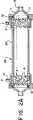
図1Aないし図2Bにおいて、同類の部材、ないし同一の部材には同じように符号が付され、二重化用の濾過組立品1が図1Aおよび図1Bに示されている。この組立品1は、第1のケーシング2を有する第1のステージと、第2のケーシング3を有する第2のステージを有して、二つの独立したステージから構成され、これらのステージが協動して、透析液といった液体の二重の濾過を行うようになっている。第1のケーシングは、濾過の前に液体を受け入れる注入口ポート5を有している。第2のケーシング3は、好ましくは患者へのオンライン式の点滴のために二重に濾過された液体ないし点滴液を排出するための排出口ポート15を有している。注入口ポート5および排出口ポート15は、ルアー(luer)といった、透析装置等と一緒に用いることのできる標準的なコネクタとすることができる。
【0014】
第1のケーシング2および第2のケーシング3は、円筒状ハウジングとされることが好ましいが、いかなる有用な形状とされていてもよい。当業者には明らかであるように、各ケーシング2,3は、内部延在部24と、液体および/または樹脂をフィルタ4の周りの空間部6内に導入することができる充填/透析液注入ポート16とを有する従来の標準的なダイアライザカートリッジと同類のものにすることができる。したがって、ケーシング2,3は、最終的な組立品にする前に、既存のダイアライザ製造装置を用いて別個に製造するか、あるいは、これとは異なり、単体のユニットとして一体に製造することができる。
【0015】
フィルタ4は、内毒素の濾過等に適した、縦長の半透性の中空ファイバ14からなる円筒状の束ないし他の膜とされていることが好ましい。したがって、フィルタ膜14は、効果的に内毒素を除去するために、高い水透過率と低分子量のカットオフ(例えば小さな孔寸法)を実現できる。とは言え、フィルタ4は、点滴用の液体を濾過するのに適したどのようなタイプのフィルタでもよい。フィルタ4は、ポリウレタン、エポキシ、あるいはその他の熱硬化性材料等の充填剤8(ポッティング剤)(potting compound)を用いてケーシング2,3内に密閉される。さらに、各ケーシング2,3の内部延在部24は、濾過に使われない流域面積を最小限にするために、注入口ポート5ないし排出口ポート15の略反対側のケーシング2,3の端部側において充填剤8(ポッティング剤)の中へ封止することができる。
【0016】
複数の充填ポート16(potting port)は、ケーシング2,3の一部として設けられ、ケーシング2,3を一緒に固定する前に充填剤8を注入することができるようになっている。複数の充填ポート16は、充填剤8の注入を受け入れるように、従来のダイアライザに見られる透析液ポートに類似の構成とすることができる。遠心充填といった、通常のダイアライザとともに用いられる通常の充填の技術や装置を用いることができるが、これは当業者にとって容易に利用できる他のどんな技術も可能であるのと同様である。過剰の充填剤8が一旦トリミングによって取り去られてフィルタ4のファイバの管腔が開口されると、二つの独立した液体の分室が各ケーシング2,3内に形成される。
【0017】
さらに、濾過組立品1の一端もしくは両端に、ステージコネクタ9,10がさらに設けられ、上記二つの液体分室が外部環境と同じくお互いの間でも封鎖される。ステージコネクタ9,10は、ケーシング2,3を一体に固定するように機能するとともに、組立品1の好ましくは両端に、ステージ間ヘッダ空間部7を形成する役割も担い、これにより、以下にさらに述べられるように、二つのケーシング2,3間における液体が流通するようになる。さらに、ステージコネクタ9,10は、外側空間部22と流通可能な注入口ポート5ないし排出口ポート15を有することができる。空間部22は、複数の充填ポート16に通じ、さらにフィルタ4の外側の部分に通じることができる。ステージコネクタ9,10は、組立品1を製造する過程で、各ケーシング2,3に周辺側で接着ないし溶着することができる。このような接着ないし溶着は、位置18,19,20および21において行われるのが好ましい。接着部19,21は、外部環境からステージ間ヘッダ空間部7を密閉することが好ましい。外部フランジ29およびケーシング2,3への接着部18,20は、濾過空間部22を外部環境から封鎖すると同時に、ケーシング2,3間を横切る流れを防止するように濾過空間部22同志の間を封鎖することが好ましい。
【0018】
ステージコネクタ9,10は、ステージ間ヘッダ空間部7を画成するように嵌合部17でステージ間ヘッダ部11に嵌合可能とされている。ステージコネクタ9,10とステージ間ヘッダ部11との間の嵌合されるつなぎ目の部分には、ステージ間ヘッダ空間部7と外部環境との間の流通を防止するために、O−リング等のシール部12を設けることができる。
【0019】
ステージ間ヘッダ部11には、さらに入口ポート13を設けることができる。入口ポート13は、現在ダイアライザ装置に見られるような、標準的なツイストロックコネクタ(twist lock connecto)として形成されていることが好ましい。とは言え、あらゆる有用なタイプのコネクタも可能である。入口ポート13は、濾過組立品1をダイアライザ再生装置に接続できるようにし、完全状態を試験できるようにし、さらに、使用後にこの入口ポート13を介して殺菌消毒できるように用いられる。
【0020】
好ましい実施形態において、入口ポート13には、濾過組立品1の通常運転中、ステージ間ヘッダ空間部7と外部環境との間の液体の流通がないように蓋が被せられる。一実施形態において、さらに考えられるのは、ステージコネクタ9、ステージ間ヘッダ部11、および入口ポート13が、別々の構成部材から組み立てられるというよりはむしろ、一つの部材として設けられてもよいということである。
【0021】
以下に、図1Aおよび図1Bの濾過組立品1の通常の運転を図を参照しながら説明する。組立品1を組み上げたら、ダイアライザといった透析装置と、患者につなげられるIV点滴セットとの間に装置を接続することができる。透析装置は、注入口ポート5と排出口ポート15との間に圧力勾配が生じるように濾過組立品1に接続される。滅菌されていない置換液等の濾過液は、注入口ポート5に接続されたチューブ(図示せず)を介して濾過組立品1に注入される。濾過液は、注入口ポート5から、ケーシング2内の第1のフィルタ4の周りの空間部6に入る。充填剤8は、濾過液が先ず第1のフィルタ4を通って濾過されないまま直接ステージ間ヘッダ空間部7に流入するのを防いでいる。充填剤8は、充填ポート16および空間部23を一端側で封鎖して、これにより濾過液が同じくこの部分を流れることがないようになっていることが好ましい。濾過液は、フィルタ4の外側の部分の中の一つないし複数の細孔を通って中空ファイバ14の管腔内に入ることができる。既に述べたように、半透性の中空ファイバ14の束によって、濾過液からの内毒素等が除去される。続いて濾過液は、フィルタ端部の一方もしくは双方(あるいはステージの排出口)を介して第1のフィルタ4から出て、画成されたステージ間ヘッダ空間部7に入る。
【0022】
組立品1を横切る圧力勾配によって、かくして、第2のステージの端部ないしステージの注入口を介して、ステージ間ヘッダ空間部7から第2のケーシング3内の第2のフィルタ4の管腔14内へと濾過液が押しやられる。充填剤8は、濾過液が先ずファイバ14に入らないままステージ間ヘッダ空間部7からファイバ14の周りの空間部6に直接入ることを防いでいる。第2のフィルタ4によって、濾過液の二重の濾過が行われる。濾過液は、第2のフィルタケーシング3の充填ポート16を介して第2のフィルタ4を出て、第2のケーシング3の周りの空間部22の中に流入する。次に、(ここでは点滴液と称される)濾過液は、排出口ポート15を介して濾過組立品1を出る。点滴液は、排出口ポート15からチューブ(図示せず)を通って患者に取り付けられたIV点滴セットに流れる。
【0023】
この方法では、一段のフィルタに支障が生じて内毒素等が直に患者の血流内へ流れてしまう可能性が、第1および第2のフィルタ4による二重の濾過によって低減される。
【0024】
図2Aないし図2Cを参照すると、図1Aないし図1Bに示された第一の実施形態と細部の多くの点が類似している二重化用の濾過組立品28の第2の実施形態が示されている。後で取り付けられる独立した複数のケーシングを作る代わりに、濾過組立品28は、好ましくは円筒状とされたただ一つの大きなケーシング25から組み立てることができる。ケーシング25は、分割リブ26によってさらに縦長の二つのセクションに分割されている。この二つの縦長のセクションは、等しい容量とされていることが好ましい。上記大型のケーシング25のこの第1の副セクションは、濾過液を受け入れるための注入口ポート5を備えている。大型のケーシング25の第2の副セクションは、今度は患者へそのまま点滴するのに用いることができる、組立品28から点滴液を排出するための排出口ポート15を備えている。
【0025】
上記大型ケーシング25の各副セクションは、好ましくは、半透性の中空ファイバ14の縦長の束とされたフィルタ4を収容するものとすることができる。好ましくは概ね円筒状で大型のケーシング25を備えるこの第2の実施形態において、図2Bに示されるように、各フィルタ4は、細分された大型のケーシング25の形状に対応させるために卵形とされていることも考えられる。とは言え、各フィルタ4は、他のどのような有用な形状とされていてもよい。濾過組立品1について述べたことと同じように、濾過組立品28において、空間部6は、濾過の前と後の液体を収容するように、大型ケーシング25の外側璧部と各フィルタ4との間に設けられている。
【0026】
大型のケーシング25が好ましくは一体型の構造とされていることから、濾過組立品1に対して示されたようなステージ間コネクタ9,10は、この濾過組立品28に対しては、必要が無くなる。その代わり、ステージ間ヘッダ部11が大型ケーシング25の一端もしくは両端に嵌合されることが好ましい。O−リング12やそれに似た類のものが、ステージ間ヘッダ部11および大型ケーシング25の嵌め合わされたつなぎ目の部分をふさぐのに用いられてもよい。ステージ間ヘッダ部11は、濾過組立品1に関して述べたような機能を持つ入口ポート13をさらに有することができる。ステージ間ヘッダ空間部7によって、大型ケーシング25の細分されたセクションの双方のフィルタ4間を液体が流通することができる。
【0027】
大型ケーシング25の細分化された部分は、充填剤8によって、外部環境からも、ステージ間ヘッダ空間部7からも閉鎖することができる。充填剤8は、従来のダイアライザにおけるように、組立品14を作る際に注入口ポート5ならびに排出口ポート15を通して大型ケーシング25内に注入することができる。あるいは、これとは異なり、充填剤8は、濾過組立品1に関して述べたように、独立した充填ポート(図示せず)を用いて注入することもできる。充填剤8は、分割リブ26の端部27が充填剤8内で封止されて、液体が個々のフィルタ4を通してそれぞれの細分化されたセクションだけから、あるいはそれぞれのセクションだけへ流れることができるように注入されることが好ましい。
【0028】
上述したような構成とされる場合には、濾過組立品28の操作は、濾過組立品1に関して述べられた典型的な例と同じようなものとなる。本発明は、これまで先の実施形態において詳細に説明されてきたが、これらの例が単なる例示を目的とするものでしかなく、単に従属請求項だけから決められるような他の変更は、形態や細部のいずれにおいても、当業者によって本発明の思想と観点から逸脱することなく本発明に対してなされ得ることを理解されたい。
【図面の簡単な説明】
【図1A】 本発明の第一の濾過組立品の正面断面図である。
【図1B】 図1の第一の濾過組立品のA−A線に沿った上面断面図である。
【図2A】 本発明の第二の濾過組立品の正面断面図である。
【図2B】 図2Aの第一の濾過組立品のA−A線に沿った上面断面図である。
【図2C】 本発明の第二の濾過組立品の側面断面図である。
【符号の説明】
1,28・・・濾過組立品
2・・・第1のケーシング
3・・・第2のケーシング
6・・・フィルタ4の周りの空間部
4・・・フィルタ(第1のフィルタ膜、第2のフィルタ膜)
5・・・注入口ポート
6・・・空間部
7・・・ステージ間ヘッダ空間部
8・・・充填剤
9,10・・・ステージコネクタ
11・・・ステージ間ヘッダ部(ステージ間の部分)
12・・・O−リング(シール部)
13・・・入口ポート
14・・・中空ファイバ
15・・・排出口ポート
16・・・充填/透析液注入ポート(充填ポート)
22・・・外側の空間部
25・・・大型ケーシング
26・・・分割リブ[0001]
BACKGROUND OF THE INVENTION
The present invention relates to an apparatus and method for disinfection and sterilization, and more particularly to an apparatus and method having filtration means for providing a sterilized infusion.
[0002]
[Prior art]
In general, patients in need of prescribed drug treatment, rehydration, blood supply, nutritional supplementation, etc. receive the corresponding sterilization solution by direct infusion into the patient's bloodstream. This is usually done by using an intravenous (IV) bag connected to a needle inserted into a patient's vein or artery via a plastic tube. In general, the IV bag normally supplies 1 to 2 liters of sterilizing solution until the stored amount is used up, and when the supply is completed, a new IV bag must be provided. Changing the IV bag can be a time consuming task. For this reason, IV IV infusion can work well for slow infusion rates and / or small doses of treatment. However, for treatments that require a large volume and / or rapid fluid supply, such as supplying a replacement fluid for blood filtration or dialysate for peritoneal dialysis, an IV bag Infusion using is not preferred.
[0003]
Instead, along with blood filtration, non-sterile fluid (non-sterile fluid) is filtered through one or a series of filtration devices and injected directly into the patient's bloodstream. The fluid to be filtered can be patient ultrafiltrate or non-sterile substitution fluid taken from an external source, which reduces the loss of patient fluid Minimized. In any case, to perform filtration with minimal risk to the patient, the filter configuration used in the process removes endotoxins, bacteria, and other pyrogen-inducing com pounds. It is necessary to If the filter fails during the process, the patient will suffer from infectious or febrile symptoms due to poorly filtered fluid.
[0004]
There are currently several filtration techniques and devices for blood filtration and dialysis. Limido et al., “Clinical Evaluation of AK-100 ULTRA for Predilution HF with On-Line Prepared Bicarbonate Substitution Fluid. Comparison with HD and Acetate Postdilution HF '; International Journal of Artificial Organs, Vol. 20, No. 3 (1997), pp. 153-157, for a method of hemodiafiltration using a single-stage dialyzer cartridge having a high flux semipermeable membrane, see P. Ahrenholz et al., "On-Line Hemodiafiltration with Pre-and Postdilution: A comparison of Efficiency", Interna-tional Journal of Artificial Organs, Vol. 20, No. 2 (1997), pp 81-90 ("Ahrenholz et al. "). See JH Miller et al.," Technical Aspects of High-Flux Hemodiafiltration for Adequate Short (Under 2 Hours) for methods of hemodiafiltration using single and double dialyzer cartridges. Treatment ", Transactions of Ameri can Society of Artificial Internal Organs (1984), pp. 377-380.
[0005]
The above and other prior art methods for on-line filtration provide a single filter as the last barrier between the dirty fluid supply for infusion and the sterile fluid supply. Finally rely on. This last filter mistake can be fatal or life threatening. In particular, dialyzer systems that rely on back-filtration of blood are dangerous. This is because it was shown that several substances that cause fever, including some endotoxins, pass through this single filter during the process. For example, R. Bigazzi, et al., “High-Permeable Membranes and Hypersensitivity-like Reactions: Role of Dialysis Fluid Contamination”, Blood Purification, Vol. 8, No. 4 (1990), pp. 190- 198 and N. Hosoya, et al., "Back Diffusion Rather than Back Filtration Enhances Endotoxin Transport Through Highly Permeable Dialysis Membranes", ASAIO Transactions, Vol. 36, No. 3 (1990), pp. M311-313 .
[0006]
[Problems to be solved by the invention]
Accordingly, there is a need to provide an independent, extra duplex sterilizing fluid filter that can be used with any device or method that produces a physiological fluid suitable for patient infusion, preferably in large quantities. Furthermore, there is a need for an independent filter that can be used with high volume and / or fast flow treatment.
[0007]
[Means for Solving the Problems]
To address the shortcomings of the prior art, a first embodiment of the present invention comprises a first sterilization stage in a filtration assembly having (1) an inlet port for taking liquid into the filtration assembly; The first sterilization stage further comprises at least one first stage outlet, and (2) a second sterilization stage having an outlet port for discharging the liquid from the filtration assembly. The second sterilization stage has at least one second stage inlet, and (3) is fixedly mounted between the first stage and the second stage. And a stage connector that circulates the liquid between the discharge port of the first stage and the injection port of the second stage.
[0008]
A second embodiment of the present invention provides a method for filtering liquid, comprising: (1) incorporating liquid at an inlet port of a casing filtration assembly; and (2) to a first filter in the casing. Transferring the liquid; (3) filtering the liquid through an outer portion of the first filter; and (4) discharging the liquid to an interstage connector through the end of the first filter. And (5) taking in the liquid from the interstage connector at the end of the second filter; and (6) from the end of the second filter to the outside of the second filter. Filtering the liquid towards a part; (7) draining the liquid from the outer part of the second filter; and (8) the outlet port at the outlet port for infusion to the patient. Receiving liquid And the process, the has.
[0009]
A third embodiment of the present invention provides a filtration assembly comprising: (1) a casing; (2) surrounding the casing with a first portion for enclosing the first filter; and for enclosing the second filter. A dividing rib for dividing into a second part so as not to flow directly between the first part and the second part; and (3) an inlet through which the flow passes to the first filter. A port, (4) an outlet port through which the flow passes to the second filter, and (5) at least one for flowing between the end of the first filter and the end of the second filter. And an interstage part.
[0010]
It is contemplated that the dual filtration assembly of the present invention can be made into multiple sections, each of these sections having a separate casing provided for later attachment, and It is also contemplated that a dual filtration assembly can be made such that both casings are provided simultaneously. It is also conceivable that a single large casing may be made with separate and separate filtration compartments that are partitioned to perform double filtration.
[0011]
An advantage of the present invention is that a dual filtration mechanism for producing a drip for a patient is reduced so that the possibility of an infectious and / or pyrogenic reaction caused by the failure of one filter is reduced. It is in that it is composed. Such a double protection cannot be obtained with prior art mechanisms.
[0012]
DETAILED DESCRIPTION OF THE INVENTION
Further objects and advantages of the present invention will become apparent to those skilled in the art from the preferred embodiment detailed below in conjunction with the drawings.
[0013]
In FIGS. 1A to 2B, the same members or the same members are similarly denoted by the same reference numerals, and a duplex filter assembly 1 is shown in FIGS. 1A and 1B. This assembly 1 has a first stage having a
[0014]
The
[0015]
The
[0016]
A plurality of
[0017]
Furthermore,
[0018]
The
[0019]
The
[0020]
In a preferred embodiment, the
[0021]
In the following, normal operation of the filtration assembly 1 of FIGS. 1A and 1B will be described with reference to the figures. Once the assembly 1 has been assembled, the device can be connected between a dialyzer, such as a dialyzer, and an IV drip set connected to the patient. The dialysis machine is connected to the filtration assembly 1 such that a pressure gradient is created between the
[0022]
Due to the pressure gradient across the assembly 1, thus through the end of the second stage or the inlet of the stage, from the interstage header space 7 to the
[0023]
In this method, the possibility that the first-stage filter is disturbed and endotoxin or the like flows directly into the bloodstream of the patient is reduced by double filtration by the first and
[0024]
Referring to FIGS. 2A-2C, there is shown a second embodiment of a
[0025]
Each subsection of the
[0026]
Since the
[0027]
The segmented portion of the
[0028]
When configured as described above, the operation of the
[Brief description of the drawings]
FIG. 1A is a front cross-sectional view of a first filtration assembly of the present invention.
1B is a top cross-sectional view of the first filtration assembly of FIG. 1 along the line AA.
FIG. 2A is a front cross-sectional view of a second filtration assembly of the present invention.
2B is a top cross-sectional view of the first filtration assembly of FIG. 2A along the line AA.
2C is a side cross-sectional view of a second filtration assembly of the present invention. FIG.
[Explanation of symbols]
DESCRIPTION OF
5 ...
12 ... O-ring (seal part)
13 ...
22 ...
Claims (26)
Translated fromJapanese該濾過組立品内に液体を取り入れる注入口ポートを有する第1の滅菌ステージを備え、この第1の滅菌ステージは、さらに少なくとも一つの第1のステージの排出口を有し、
かつ、該濾過組立品から前記液体を排出するための排出口ポートを有する第2の滅菌ステージを備え、この第2の滅菌ステージは、少なくとも一つの第2のステージの注入口を有し、
かつ、前記第1のステージと前記第2のステージとの間に固定するように取り付けられて、前記第1のステージの排出口と前記第2のステージの注入口との間に前記液体を流通させるステージコネクタを備えおり、
前記第1のステージは、第1の端部と第2の端部とを有し、略前記第1の端部と前記第2の端部との間にケーシングが配置され、
前記第2のステージは、第3の端部と第4の端部とを有し、略前記第2の端部と前記第4の端部との間に第2のケーシングが配置され、
前記第1のケーシング内に配置された第1のフィルタ膜であって、前記液体は、当該第1のフィルタ膜を介して前記注入口ポートと前記第1の排出口との間を流通するように構成されている、第1のフィルタ膜と、
前記第2のケーシング内に配置された第2のフィルタ膜であって、前記液体は、当該第2のフィルタ膜を介して前記第1の注入口の端部と前記排出口ポートとの間で流通するように構成されている、第2のフィルタ膜と、
を備えており、
前記第1のフィルタ膜と前記第1のケーシングとの間に挿入された充填剤と、前記第2のフィルタ膜と前記第2のケーシングとの間に挿入された充填剤とをさらに備え、前記充填剤によって、前記液体が前記第1のケーシングおよび前記第2のケーシングと前記ステージコネクタとの間を直に流れないように構成され、
前記液体は、前記第1のフィルタの周りの空間から前記第1のフィルタの外側の部分を通して前記第1のフィルタに入り、前記第2のフィルタの外側の部分を通して出ることを特徴とする濾過組立品。In the filtration assembly,
A first sterilization stage having an inlet port for taking a liquid into the filtration assembly, the first sterilization stage further comprising an outlet of at least one first stage;
And a second sterilization stage having an outlet port for discharging the liquid from the filtration assembly, the second sterilization stage having at least one second stage inlet,
And it is attached so that it may fix between the said 1st stage and the said 2nd stage, and distribute | circulates the said liquid between the discharge port of the said 1st stage, and the injection port of the said 2nd stage Equipped with a stage connector,
The first stage has a first end and a second end, and a casing is disposed substantially between the first end and the second end,
The second stage has a third end portion and a fourth end portion, and a second casing is disposed substantially between the second end portion and the fourth end portion,
A first filter membrane disposed in the first casing, wherein the liquid flows between the inlet port and the first outlet through the first filter membrane. A first filter membrane configured to:
A second filter membrane disposed in the second casing, wherein the liquid passes between the end of the first inlet and the outlet port via the second filter membrane. A second filter membrane configured to circulate;
With
A filler inserted between the first filter membrane and the first casing; and a filler inserted between the second filter membrane and the second casing; The liquid is configured so that the liquid does not flow directly between the first casing and the second casing and the stage connector,
The liquid is filtered tothe first incoming through the outer portion from the space of the first filter around the filter to the first filter, wherein Rukotoout through the outer portion of the second filter Assembly.
前記第1のステージおよび前記第2のステージは、略互いに平行に配置されていることを特徴とする濾過組立品。The filtration assembly of claim 1,
The filtration assembly according to claim 1, wherein the first stage and the second stage are arranged substantially parallel to each other.
前記第1のステージおよび第2のステージは、一体に取り付けられていることを特徴とする濾過組立品。The filtration assembly of claim 1,
The filtration assembly according to claim 1, wherein the first stage and the second stage are integrally attached.
操作により前記ステージコネクタに接続されるステージ間ヘッダ部をさらに備え、該ステージ間ヘッダ部は、該濾過組立品への液体および空気の少なくとも一つを受け入れるための入口ポートをさらに備えていることを特徴とする濾過組立品。The filtration assembly of claim 1,
An interstage header portion connected to the stage connector by operation, the interstage header portion further comprising an inlet port for receiving at least one of liquid and air to the filtration assembly; Characteristic filtration assembly.
該濾過組立品の動作中、前記入口ポートに蓋が被せられるように構成されていることを特徴とする濾過組立品。The filtration assembly according toclaim 4 ,
A filtration assembly configured to cover the inlet port during operation of the filtration assembly.
前記入口ポートは、該濾過組立品を十分に殺菌消毒して洗浄するための消毒剤が取り入れられるように構成されていることを特徴とする濾過組立品。The filtration assembly according toclaim 4 ,
A filtration assembly, wherein the inlet port is configured to receive a disinfectant for sufficiently sterilizing and cleaning the filtration assembly.
前記ステージ間ヘッダ部と前記ステージコネクタとの間のつなぎ目をふさぐためのシール部をさらに有していることを特徴とする濾過組立品。The filtration assembly according toclaim 4 ,
The filtration assembly further comprising a seal portion for closing a joint between the interstage header portion and the stage connector.
前記シール部はO−リングとされていることを特徴とする濾過組立品。The filtration assembly according toclaim 7 ,
The filtration assembly according to claim 1, wherein the seal portion is an O-ring.
前記第1のフィルタ膜および前記第2のフィルタ膜の少なくとも一つは、前記液体が前記排出口ポートに入る前に、予め前記液体から内毒素およびバクテリアを除去する効果を有していることを特徴とする濾過組立品。The filtration assembly ofclaim 1 ,
At least one of the first filter membrane and the second filter membrane has an effect of removing endotoxin and bacteria from the liquid in advance before the liquid enters the outlet port. Characteristic filtration assembly.
前記第1のフィルタ膜および前記第2のフィルタ膜の少なくとも一つは、半透性の中空ファイバの束を有していることを特徴とする濾過組立品。The filtration assembly according toclaim 9 ,
At least one of the first filter membrane and the second filter membrane has a bundle of semi-permeable hollow fibers.
前記第1のステージおよび前記第2のステージの少なくとも一つは、概略円筒状とされていることを特徴とする濾過組立品。The filtration assembly ofclaim 1 ,
At least one of the first stage and the second stage has a substantially cylindrical shape.
前記第1のフィルタ膜および前記第2のフィルタ膜の少なくとも一つは、概略円筒状とされていることを特徴とする濾過組立品。The filtration assembly ofclaim 1 ,
At least one of said 1st filter membrane and said 2nd filter membrane is made into the substantially cylindrical shape, The filtration assembly characterized by the above-mentioned.
前記第1のステージの排出口は、前記第1のステージの端部にあることを特徴とする濾過組立品。The filtration assembly of claim 1,
The filtration assembly according to claim 1, wherein the discharge port of the first stage is at an end of the first stage.
前記第2のステージの注入口は、前記第2のステージの端部にあることを特徴とする濾過組立品。The filtration assembly of claim 1,
The filtration assembly according to claim 2, wherein the inlet of the second stage is at an end of the second stage.
前記注入口ポートに流れが通じている第1のフィルタの外側の部分を通して前記液体を濾過し、
前記第1のフィルタの端部を通してステージ間コネクタに前記液体を排出し、
前記第1のフィルタに対して略平行に配置された第2のフィルタの端部で、前記ステージ間コネクタからの前記液体を取り入れ、
前記第2のフィルタの前記端部から、前記第2のフィルタの外側の部分へ前記液体を濾過し、
排出口ポートを通して前記液体を排出する、
液体を濾過するための方法。Intake liquid at the inlet port of the filtration assembly,
Filtering the liquid through the outer portion of the first filter in flow through the inlet port;
Discharging the liquid to the interstage connector through the end of the first filter;
Taking in the liquid from the interstage connector at the end of a second filter arranged substantially parallel to the first filter;
Filtering the liquid from the end of the second filter to a portion outside the second filter;
Discharging the liquid throughdischarge outlet port,
A method for filtering liquid.
前記ケーシングを、第1のフィルタを囲むための第1の部分、および第2のフィルタを囲むための第2の部分に分割して、前記第1の部分と前記第2の部分との間で直接流通させないようにするための分割リブと、
前記第1のフィルタに流れが通じる注入口ポートと、
前記第2のフィルタに流れが通じる排出口ポートと、
前記第1のフィルタの第1の端部と前記第2のフィルタの第2の端部との間を流通させるための少なくとも一つのステージ間部分と、
を備え、
前記液体は、前記第1のフィルタの周りの空間から前記第1のフィルタの外側の部分を通して前記第1のフィルタに入り、前記第2のフィルタの外側の部分を通して出る濾過組立品。A casing,
The casing is divided into a first part for enclosing the first filter and a second part for enclosing the second filter, between the first part and the second part. Split ribs to prevent direct distribution,
An inlet port through which flow passes to the first filter;
An outlet port through which flow flows to the second filter;
At least one interstage portion for flowing between a first end of the first filter and a second end of the second filter;
Equipped witha,
The liquid, the first from the space around the filter enters the first filter through the outer portion of the first filter, the filtration assembly Ruout through the outer portion of the second filter.
前記ケーシングと少なくとも一つのステージ間の部分との間における液体の直接の流通を妨げるための、前記第1のフィルタと前記ケーシングとの間に配置された充填剤をさらに備えていることを特徴とする濾過組立品。The filtration assembly ofclaim 16 ,
And further comprising a filler disposed between the first filter and the casing for preventing direct flow of liquid between the casing and a portion between the at least one stage. Filtration assembly.
前記少なくとも一つのステージ間の部分は、消毒剤および空気の少なくとも一つを取り入れるための入口ポートを備えていることを特徴とする濾過組立品。The filtration assembly ofclaim 16 ,
A filtration assembly, wherein the portion between the at least one stage comprises an inlet port for taking in at least one of a disinfectant and air.
前記濾過組立品の動作中、前記入口ポートに蓋が被せられるように構成されていることを特徴とする濾過組立品。The filtration assembly according toclaim 18 ,
The filtration assembly is configured to cover the inlet port during operation of the filtration assembly.
前記少なくとも一つのステージ間の部分は、該ステージ間の部分と前記ケーシングとの間のつなぎ目をふさぐためのシール部を備えていることを特徴とする濾過組立品。The filtration assembly ofclaim 16 ,
The filtration assembly according to claim 1, wherein a portion between the at least one stage includes a seal portion for closing a joint between the portion between the stage and the casing.
前記シール部は、O−リングとされていることを特徴とする濾過組立品。The filtration assembly ofclaim 20 ,
The filtration assembly according to claim 1, wherein the seal portion is an O-ring.
前記第1のフィルタおよび前記第2のフィルタをさらに備えていることを特徴とする濾過組立品。The filtration assembly ofclaim 16 ,
The filtration assembly further comprising the first filter and the second filter.
前記第1のフィルタおよび前記第2のフィルタの少なくとも一つは、概略卵形とされていることを特徴とする濾過組立品。The filtration assembly ofclaim 16 ,
At least one of the first filter and the second filter has a generally oval shape.
前記第1のフィルタおよび前記第2のフィルタの少なくとも一つは、概略円筒状とされていることを特徴とする濾過組立品。The filtration assembly ofclaim 16 ,
At least one of the first filter and the second filter has a substantially cylindrical shape.
前記ケーシングは、概略円筒状とされていることを特徴とする濾過組立品。The filtration assembly ofclaim 16 ,
The filtration assembly according to claim 1, wherein the casing is substantially cylindrical.
充填剤を受け入れるための充填ポートをさらに備えていることを特徴とする濾過組立品。The filtration assembly ofclaim 16 ,
A filtration assembly further comprising a fill port for receiving a filler.
Applications Claiming Priority (3)
| Application Number | Priority Date | Filing Date | Title |
|---|---|---|---|
| US09/477,081 | 1999-12-30 | ||
| US09/477,081US6635179B1 (en) | 1999-12-30 | 1999-12-30 | Sterile fluid filtration cartridge and method for using same |
| PCT/US2000/035716WO2001049398A1 (en) | 1999-12-30 | 2000-12-29 | Sterile fluid filtration cartridge and method for using same |
Publications (2)
| Publication Number | Publication Date |
|---|---|
| JP2003518995A JP2003518995A (en) | 2003-06-17 |
| JP4623909B2true JP4623909B2 (en) | 2011-02-02 |
Family
ID=23894457
Family Applications (1)
| Application Number | Title | Priority Date | Filing Date |
|---|---|---|---|
| JP2001549758AExpired - Fee RelatedJP4623909B2 (en) | 1999-12-30 | 2000-12-29 | Sterile liquid filtration cartridge and method using the same |
Country Status (9)
| Country | Link |
|---|---|
| US (1) | US6635179B1 (en) |
| EP (1) | EP1251943B1 (en) |
| JP (1) | JP4623909B2 (en) |
| AT (1) | ATE340015T1 (en) |
| AU (1) | AU2745501A (en) |
| CA (1) | CA2395697A1 (en) |
| DE (1) | DE60030885T2 (en) |
| ES (1) | ES2272358T3 (en) |
| WO (1) | WO2001049398A1 (en) |
Families Citing this family (65)
| Publication number | Priority date | Publication date | Assignee | Title |
|---|---|---|---|---|
| ES2353254T3 (en) | 1996-12-20 | 2011-02-28 | Siemens Water Technologies Corp. | WASHING PROCEDURE |
| US6776912B2 (en)* | 1999-12-23 | 2004-08-17 | Membrana Gmbh | Hemodiafiltration system and method |
| FR2809969B1 (en)* | 2000-06-09 | 2003-09-26 | Bio Merieux | PREPARATION OF A SAMPLE TO BE ANALYZED FROM A VERY LARGE SAMPLE |
| AUPR064800A0 (en)* | 2000-10-09 | 2000-11-02 | Usf Filtration And Separations Group Inc. | Improved membrane filtration system |
| AUPR143400A0 (en) | 2000-11-13 | 2000-12-07 | Usf Filtration And Separations Group Inc. | Modified membranes |
| US6758975B2 (en)* | 2001-02-16 | 2004-07-06 | Piedmont Renal Clinic, Pa | Automated peritoneal dialysis system and process with in-line sterilization of dialysate |
| AUPR421501A0 (en) | 2001-04-04 | 2001-05-03 | U.S. Filter Wastewater Group, Inc. | Potting method |
| AUPR584301A0 (en) | 2001-06-20 | 2001-07-12 | U.S. Filter Wastewater Group, Inc. | Membrane polymer compositions |
| AUPR692401A0 (en) | 2001-08-09 | 2001-08-30 | U.S. Filter Wastewater Group, Inc. | Method of cleaning membrane modules |
| US7247238B2 (en) | 2002-02-12 | 2007-07-24 | Siemens Water Technologies Corp. | Poly(ethylene chlorotrifluoroethylene) membranes |
| AUPS300602A0 (en) | 2002-06-18 | 2002-07-11 | U.S. Filter Wastewater Group, Inc. | Methods of minimising the effect of integrity loss in hollow fibre membrane modules |
| KR101002466B1 (en) | 2002-10-10 | 2010-12-17 | 지멘스 워터 테크놀로지스 코포레이션 | Back wash method |
| AU2002953111A0 (en) | 2002-12-05 | 2002-12-19 | U. S. Filter Wastewater Group, Inc. | Mixing chamber |
| AU2003903507A0 (en) | 2003-07-08 | 2003-07-24 | U. S. Filter Wastewater Group, Inc. | Membrane post-treatment |
| NZ545206A (en) | 2003-08-29 | 2009-03-31 | Siemens Water Tech Corp | Backwash |
| CA2544626C (en) | 2003-11-14 | 2016-01-26 | U.S. Filter Wastewater Group, Inc. | Closed aeration and backwash device for use with membrane filtration module |
| US7128836B2 (en)* | 2004-03-08 | 2006-10-31 | Potito De Paolis | Dialysis device |
| US8758621B2 (en) | 2004-03-26 | 2014-06-24 | Evoqua Water Technologies Llc | Process and apparatus for purifying impure water using microfiltration or ultrafiltration in combination with reverse osmosis |
| JP2007535398A (en) | 2004-04-22 | 2007-12-06 | シーメンス ウォーター テクノロジース コーポレイション | Filtration device including membrane bioreactor and treatment tank for digesting organic substances, and waste liquid treatment method |
| US7192131B2 (en)* | 2004-05-12 | 2007-03-20 | Hewlett-Packard Development Company, L.P. | Filter element carrier, filter, ink pen |
| CN102512986A (en) | 2004-07-02 | 2012-06-27 | 西门子工业公司 | Gas transfer membrane |
| EP1773477B1 (en) | 2004-07-05 | 2011-09-07 | Siemens Water Technologies Corp. | Hydrophilic membranes |
| CN101052457B (en) | 2004-08-20 | 2012-07-04 | 西门子工业公司 | Square mbr manifold system |
| CN101043933B (en) | 2004-09-07 | 2012-09-05 | 西门子工业公司 | Reduction of backwash liquid waste |
| AU2005284677B2 (en) | 2004-09-14 | 2010-12-23 | Evoqua Water Technologies Llc | Methods and apparatus for removing solids from a membrane module |
| NZ553771A (en) | 2004-09-15 | 2010-11-26 | Siemens Water Tech Corp | Continuously variable aeration of membrane filtration system and flow control device when used in such application |
| US20060081524A1 (en)* | 2004-10-15 | 2006-04-20 | Amitava Sengupta | Membrane contactor and method of making the same |
| US7591950B2 (en) | 2004-11-02 | 2009-09-22 | Siemens Water Technologies Corp. | Submerged cross-flow filtration |
| KR20070089981A (en) | 2004-12-03 | 2007-09-04 | 지멘스 워터 테크놀로지스 코포레이션 | Post-treatment of membrane |
| WO2006066350A1 (en) | 2004-12-24 | 2006-06-29 | Siemens Water Technologies Corp. | Simple gas scouring method and apparatus |
| WO2006066319A1 (en) | 2004-12-24 | 2006-06-29 | Siemens Water Technologies Corp. | Cleaning in membrane filtration systems |
| JP2008539054A (en) | 2005-04-29 | 2008-11-13 | シーメンス・ウォーター・テクノロジーズ・コーポレイション | Chemical cleaning for membrane filters |
| CN101222972B (en) | 2005-07-14 | 2014-12-03 | 伊沃夸水处理技术有限责任公司 | Monopersulfate treatment of membranes |
| US8858796B2 (en) | 2005-08-22 | 2014-10-14 | Evoqua Water Technologies Llc | Assembly for water filtration using a tube manifold to minimise backwash |
| WO2007044345A2 (en) | 2005-10-05 | 2007-04-19 | Siemens Water Technologies Corp. | Method and apparatus for treating wastewater |
| US20070138090A1 (en) | 2005-10-05 | 2007-06-21 | Jordan Edward J | Method and apparatus for treating wastewater |
| US7455765B2 (en) | 2006-01-25 | 2008-11-25 | Siemens Water Technologies Corp. | Wastewater treatment system and method |
| US8293098B2 (en) | 2006-10-24 | 2012-10-23 | Siemens Industry, Inc. | Infiltration/inflow control for membrane bioreactor |
| US8318028B2 (en) | 2007-04-02 | 2012-11-27 | Siemens Industry, Inc. | Infiltration/inflow control for membrane bioreactor |
| US9764288B2 (en) | 2007-04-04 | 2017-09-19 | Evoqua Water Technologies Llc | Membrane module protection |
| CA2688455C (en) | 2007-05-29 | 2019-12-03 | Siemens Water Technologies Corp. | Pulsed random two phase gas/liquid flow for cleaning membrane surfaces |
| US7736328B2 (en) | 2007-07-05 | 2010-06-15 | Baxter International Inc. | Dialysis system having supply container autoconnection |
| US8114276B2 (en) | 2007-10-24 | 2012-02-14 | Baxter International Inc. | Personal hemodialysis system |
| WO2010009518A1 (en) | 2008-07-24 | 2010-01-28 | Siemens Water Technologies Corp. | Frame system for membrane filtration modules |
| JP2012500117A (en) | 2008-08-20 | 2012-01-05 | シーメンス ウォーター テクノロジース コーポレイション | Improving backwash energy efficiency of membrane filtration systems. |
| AU2010101488B4 (en) | 2009-06-11 | 2013-05-02 | Evoqua Water Technologies Llc | Methods for cleaning a porous polymeric membrane and a kit for cleaning a porous polymeric membrane |
| WO2011136888A1 (en) | 2010-04-30 | 2011-11-03 | Siemens Industry, Inc | Fluid flow distribution device |
| WO2012040412A1 (en) | 2010-09-24 | 2012-03-29 | Siemens Industry, Inc. | Fluid control manifold for membrane filtration system |
| WO2013048801A1 (en) | 2011-09-30 | 2013-04-04 | Siemens Industry, Inc. | Improved manifold arrangement |
| KR102177864B1 (en) | 2011-09-30 | 2020-11-13 | 에보쿠아 워터 테크놀로지스 엘엘씨 | Isolation valve |
| WO2014004645A1 (en) | 2012-06-28 | 2014-01-03 | Siemens Industry, Inc. | A potting method |
| KR20150054918A (en) | 2012-09-14 | 2015-05-20 | 에보쿠아 워터 테크놀로지스 엘엘씨 | A polymer blend for membranes |
| DE112013004713T5 (en) | 2012-09-26 | 2015-07-23 | Evoqua Water Technologies Llc | Membrane safety device |
| AU2013231145B2 (en) | 2012-09-26 | 2017-08-17 | Evoqua Water Technologies Llc | Membrane potting methods |
| AU2013323934A1 (en) | 2012-09-27 | 2015-02-26 | Evoqua Water Technologies Llc | Gas scouring apparatus for immersed membranes |
| WO2014088882A2 (en)* | 2012-12-03 | 2014-06-12 | Emd Millipore Corporation | Methods and devices used for redundant sterile filtration |
| EP3052221B1 (en) | 2013-10-02 | 2022-12-14 | Rohm & Haas Electronic Materials Singapore Pte. Ltd | Device for repairing a membrane filtration module |
| CN106413775B (en)* | 2014-04-11 | 2019-08-20 | 福建省百仕韦医用高分子股份有限公司 | Precision filter medical infusion connector |
| US10322375B2 (en) | 2015-07-14 | 2019-06-18 | Evoqua Water Technologies Llc | Aeration device for filtration system |
| WO2017100621A1 (en) | 2015-12-11 | 2017-06-15 | Nxstage Medical, Inc. | Fluid line connector devices methods and systems |
| US11045596B2 (en) | 2016-05-06 | 2021-06-29 | Gambro Lundia Ab | Systems and methods for peritoneal dialysis having point of use dialysis fluid preparation using water accumulator and disposable set |
| US10981118B2 (en)* | 2016-07-20 | 2021-04-20 | Conor Collins | Method and apparatus for purifying the dispersing liquid in a colloidal dispersion |
| EP3415225B1 (en)* | 2017-06-14 | 2021-03-03 | Gambro Lundia AB | System and method for filtration and/or dilation of fluids |
| US10926019B2 (en) | 2019-06-05 | 2021-02-23 | Choon Kee Lee | Gradient dialysate hemodiafiltration |
| CN119258246B (en)* | 2024-12-09 | 2025-02-18 | 安徽省宿州市立医院 | A filtering and antibacterial device for hemodialysis machine in nephrology |
Family Cites Families (58)
| Publication number | Priority date | Publication date | Assignee | Title |
|---|---|---|---|---|
| US3579441A (en) | 1968-04-19 | 1971-05-18 | Hydronautics | Blood purification by dual filtration |
| US3946731A (en) | 1971-01-20 | 1976-03-30 | Lichtenstein Eric Stefan | Apparatus for extracorporeal treatment of blood |
| FR2199014B1 (en) | 1972-09-12 | 1975-03-14 | Rhone Poulenc Ind | |
| FR2231421B1 (en) | 1973-05-30 | 1976-05-07 | Rhone Poulenc Ind | |
| US4118314A (en) | 1974-01-09 | 1978-10-03 | Seisan Kaihatsu Kagaku Kenkyusho | Apparatus for treatment of artificial kidney dialyzing fluid |
| US3976576A (en) | 1974-04-01 | 1976-08-24 | The University Of Utah | Dialyzer cartridge |
| US3878095A (en) | 1974-05-02 | 1975-04-15 | Advanced Medical Sciences Inc | Dialysis apparatus |
| DE2542438C3 (en)* | 1975-09-24 | 1981-01-22 | Dr. Eduard Fresenius Chemisch-Pharmazeutische Industrie Kg Apparatebau Kg, 6380 Bad Homburg | Dialyzer |
| US4289623A (en)* | 1975-11-05 | 1981-09-15 | Extracorporeal Medical Specialties, Inc. | Hollow fiber dialysis |
| US4134834A (en) | 1976-01-06 | 1979-01-16 | Artificial And Transplant Organs, Inc. | Hemodialysis apparatus |
| DE2646358C2 (en)* | 1976-10-14 | 1982-05-13 | Dr. Eduard Fresenius, Chemisch-pharmazeutische Industrie KG Apparatebau KG, 6380 Bad Homburg | Hollow fiber dialyzer |
| DE2803344C3 (en) | 1978-01-26 | 1981-09-24 | Sartorius GmbH, 3400 Göttingen | Device for mass transfer between fluids with the interposition of a membrane |
| DE2838414C2 (en) | 1978-09-02 | 1984-10-31 | Fresenius AG, 6380 Bad Homburg | Device for hemodialysis and for withdrawing ultrafiltrate |
| FR2447196A1 (en)* | 1979-01-23 | 1980-08-22 | Sodip Sa | MEDICAL EXCHANGER-SEPARATOR WITH MEMBRANES |
| JPS5814223B2 (en) | 1979-02-24 | 1983-03-17 | 株式会社メデクス | Dialysis “filtration” device |
| JPS5649160A (en) | 1979-04-09 | 1981-05-02 | Brumfield Robert Clarence | Substance transporter and its manufacture |
| SE423318B (en) | 1980-06-27 | 1982-05-03 | Gambro Ab | MEMO Filtration System |
| US4381999A (en) | 1981-04-28 | 1983-05-03 | Cobe Laboratories, Inc. | Automatic ultrafiltration control system |
| SE425216B (en) | 1981-10-05 | 1982-09-13 | Gambro Ab | A filtering |
| SE427619B (en) | 1981-10-05 | 1983-04-25 | Gambro Lundia Ab | A filtering |
| US4647378A (en) | 1983-03-23 | 1987-03-03 | Nihon Medical Engineering Co., Ltd. | Blood dialyzing method and apparatus |
| DE3444671A1 (en) | 1984-12-07 | 1986-06-12 | Fresenius AG, 6380 Bad Homburg | HAEMODIA FILTRATION DEVICE |
| FR2582536B1 (en)* | 1985-05-29 | 1987-08-21 | Framatome Sa | DEVICE FOR ULTRAFILTRATION OF A HIGH-TEMPERATURE PRESSURE LIQUID |
| DE3529973A1 (en) | 1985-08-22 | 1987-03-05 | Braun Melsungen Ag | DEVICE FOR HAEMODIAFILTRATION |
| DE3641843A1 (en) | 1986-12-08 | 1988-06-16 | Fresenius Ag | HAEMODIALYSIS DEVICE WITH STERILIZER |
| DE3709432A1 (en)* | 1987-03-21 | 1988-10-06 | Fresenius Ag | CAPILLARY FILTER ARRANGEMENT FOR THE STERILIZATION OF LIQUID MEDIA |
| FI885009L (en) | 1987-11-02 | 1989-05-03 | Tokyo Bi Tech Lab Inc | FIBERMEMBRAN SAMT FOERFARANDE OCH ANORDNING FOER RENGOERING AV BLOD. |
| IT1215765B (en) | 1988-01-22 | 1990-02-22 | Grace W R & Co | ERELATIVE HEMODIAFILTRATION DEVICE HEMODIAFILTRATION PROCEDURE. |
| FR2629361B1 (en)* | 1988-03-29 | 1991-10-25 | Lyonnaise Eaux | METHOD FOR MANUFACTURING A TUBULAR PLATE FOR A HOLLOW FIBER SEPARATION APPARATUS, AND DEVICES OBTAINED |
| US4929259A (en)* | 1989-02-09 | 1990-05-29 | The Dow Chemical Company | Hollow fiber membrane fluid separation module for boreside feed |
| US5017293A (en)* | 1989-08-24 | 1991-05-21 | Pfizer Hospital Products Group, Inc. | Multi-pass blood washing and plasma removal device and method |
| US5069788A (en)* | 1989-08-24 | 1991-12-03 | Pfizer Hospital Products Groups, Inc. | Multi-pass blood washing and plasma removal device and method |
| US5013437A (en)* | 1989-10-30 | 1991-05-07 | The Dow Chemical Company | Hollow fiber membrane fluid separation device adapted for boreside feed which contains multiple concentric stages |
| US5194157A (en) | 1990-03-09 | 1993-03-16 | Sorin Biomedica Emodialisi Srl | Blood purifying equipment particularly for the treatment of patients suffering from renal insufficiency, and a method of producing a reinfusion liquid for haemodiafiltration (HDF) |
| FR2660866B1 (en) | 1990-04-13 | 1992-06-12 | Hogamed | PROCESS AND DEVICE FOR PREPARING A SUBSTITUTION LIQUID. |
| US5238561A (en)* | 1990-09-27 | 1993-08-24 | Terumo Kabushiki Kaisha | Hollow fiber mass transfer apparatus |
| DK172894B1 (en) | 1991-01-03 | 1999-09-27 | Niels Aage Aunsholt | hemodialysis |
| US5486286A (en) | 1991-04-19 | 1996-01-23 | Althin Medical, Inc. | Apparatus for performing a self-test of kidney dialysis membrane |
| US5176725A (en)* | 1991-07-26 | 1993-01-05 | Air Products And Chemicals, Inc. | Multiple stage countercurrent hollow fiber membrane module |
| FR2680975B1 (en) | 1991-09-10 | 1998-12-31 | Hospal Ind | ARTIFICIAL KIDNEY WITH MEANS FOR DETERMINING A SUBSTANCE IN BLOOD. |
| US5244568A (en) | 1991-11-15 | 1993-09-14 | Baxter International Inc. | Automated hemodialysis chemical treatment system with control valve and proportioning pumps |
| FR2691364B1 (en) | 1992-05-19 | 1999-08-20 | Hospal Ind | ARTIFICIAL KIDNEY WITH DIALYSIS LIQUID FILTERING DEVICE. |
| US5282964A (en)* | 1993-02-19 | 1994-02-01 | The Dow Chemical Company | Boreside feed hollow fiber membrane device |
| DE4309410A1 (en) | 1993-03-19 | 1995-02-16 | Stange Jan | Material, process and equipment for the selective separation of freely dissolved and substance-bound substances from liquid substance mixtures as well as process for the production of the material |
| FR2704432B1 (en) | 1993-04-27 | 1995-06-23 | Hospal Ind | DEVICE FOR INJECTING LIQUID INTO AN EXTRACORPOREAL BLOOD CIRCUIT. |
| US5660772A (en) | 1993-09-27 | 1997-08-26 | Alfred University | Process for making ultra-fine barium hexaferrite particles |
| DE19523505A1 (en) | 1994-07-13 | 1996-01-18 | Fresenius Ag | Haemodiafiltration appliance with blood filter divided by membrane into two chambers |
| EP0701826B1 (en) | 1994-09-02 | 2000-03-22 | Terumo Kabushiki Kaisha | Dialyzer |
| US5591344A (en) | 1995-02-13 | 1997-01-07 | Aksys, Ltd. | Hot water disinfection of dialysis machines, including the extracorporeal circuit thereof |
| DE19534417A1 (en) | 1995-09-16 | 1997-03-20 | Fresenius Ag | Method for checking at least one filter arranged in the dialysis fluid system of a device for extracorporeal blood treatment |
| DE19607162C2 (en) | 1996-02-26 | 1998-01-15 | Fresenius Ag | Use of a two module dialyzer to perform a method of filtering and immediately using substituate fluid in a hemodial filtration device |
| US5902336A (en) | 1996-10-15 | 1999-05-11 | Mirimedical, Inc. | Implantable device and method for removing fluids from the blood of a patient method for implanting such a device and method for treating a patient experiencing renal failure |
| DE19700466A1 (en) | 1997-01-09 | 1998-07-16 | Polaschegg Hans Dietrich Dr | Hemodiafiltration device and method |
| WO1998050090A1 (en) | 1997-05-08 | 1998-11-12 | Scitec K.K. | Bacteria removing filter unit for hemodialyzer and hemodialyzer with bacteria removing filter |
| IT1293309B1 (en) | 1997-07-09 | 1999-02-16 | Sis Ter Spa | BLOOD TREATMENT EQUIPMENT WITH MEMBRANE EXCHANGE DEVICE |
| US5942112A (en) | 1997-10-17 | 1999-08-24 | Ishak; Noshi A. | Hollow fiber ultradialyzer apparatus |
| SE515122C2 (en) | 1999-01-29 | 2001-06-11 | Gambro Lundia Ab | Filters and method of manufacturing filters for dialysis |
| US6315895B1 (en)* | 1999-12-30 | 2001-11-13 | Nephros, Inc. | Dual-stage hemodiafiltration cartridge |
- 1999
- 1999-12-30USUS09/477,081patent/US6635179B1/ennot_activeExpired - Fee Related
- 2000
- 2000-12-29ESES00990428Tpatent/ES2272358T3/ennot_activeExpired - Lifetime
- 2000-12-29AUAU27455/01Apatent/AU2745501A/ennot_activeAbandoned
- 2000-12-29DEDE60030885Tpatent/DE60030885T2/ennot_activeExpired - Fee Related
- 2000-12-29WOPCT/US2000/035716patent/WO2001049398A1/enactiveIP Right Grant
- 2000-12-29ATAT00990428Tpatent/ATE340015T1/ennot_activeIP Right Cessation
- 2000-12-29EPEP00990428Apatent/EP1251943B1/ennot_activeExpired - Lifetime
- 2000-12-29CACA002395697Apatent/CA2395697A1/ennot_activeAbandoned
- 2000-12-29JPJP2001549758Apatent/JP4623909B2/ennot_activeExpired - Fee Related
Also Published As
| Publication number | Publication date |
|---|---|
| JP2003518995A (en) | 2003-06-17 |
| ES2272358T3 (en) | 2007-05-01 |
| ATE340015T1 (en) | 2006-10-15 |
| CA2395697A1 (en) | 2001-07-12 |
| EP1251943A1 (en) | 2002-10-30 |
| WO2001049398A1 (en) | 2001-07-12 |
| US6635179B1 (en) | 2003-10-21 |
| DE60030885D1 (en) | 2006-11-02 |
| AU2745501A (en) | 2001-07-16 |
| EP1251943B1 (en) | 2006-09-20 |
| DE60030885T2 (en) | 2007-02-08 |
| EP1251943A4 (en) | 2004-03-24 |
Similar Documents
| Publication | Publication Date | Title |
|---|---|---|
| JP4623909B2 (en) | Sterile liquid filtration cartridge and method using the same | |
| CA2427252C (en) | Dual-stage filtration cartridge | |
| JP4094946B2 (en) | Method and apparatus for producing sterile infusion | |
| JP4053421B2 (en) | Hemodiafiltration / blood filtration cartridge | |
| US6620119B1 (en) | Reusable blood lines | |
| US4702829A (en) | Hemodiafiltration apparatus | |
| US5498338A (en) | Peritoneal dialysis system using reverse osmosis purification device | |
| US4707335A (en) | System and apparatus for disinfecting, for reuse, separation devices for blood and associated fluid lines | |
| JP3831048B2 (en) | Dialyzer | |
| JP4213384B2 (en) | Two-stage hemodiafiltration cartridge | |
| US5942112A (en) | Hollow fiber ultradialyzer apparatus | |
| EP1590014B1 (en) | Integrated module for blood treatment and assembly process | |
| US4552721A (en) | Method for disinfecting, for reuse, separation devices for blood and associated fluid lines | |
| WO2001002035A1 (en) | Method for regenerating dialyser and dialysis apparatus | |
| HK1058162B (en) | Dual-stage filtration cartridge | |
| JPS62236554A (en) | Blood purifying apparatus and its use |
Legal Events
| Date | Code | Title | Description |
|---|---|---|---|
| A621 | Written request for application examination | Free format text:JAPANESE INTERMEDIATE CODE: A621 Effective date:20071207 | |
| A131 | Notification of reasons for refusal | Free format text:JAPANESE INTERMEDIATE CODE: A131 Effective date:20100511 | |
| A601 | Written request for extension of time | Free format text:JAPANESE INTERMEDIATE CODE: A601 Effective date:20100810 | |
| A602 | Written permission of extension of time | Free format text:JAPANESE INTERMEDIATE CODE: A602 Effective date:20100817 | |
| A521 | Request for written amendment filed | Free format text:JAPANESE INTERMEDIATE CODE: A523 Effective date:20100903 | |
| TRDD | Decision of grant or rejection written | ||
| A01 | Written decision to grant a patent or to grant a registration (utility model) | Free format text:JAPANESE INTERMEDIATE CODE: A01 Effective date:20101005 | |
| A01 | Written decision to grant a patent or to grant a registration (utility model) | Free format text:JAPANESE INTERMEDIATE CODE: A01 | |
| A61 | First payment of annual fees (during grant procedure) | Free format text:JAPANESE INTERMEDIATE CODE: A61 Effective date:20101102 | |
| R150 | Certificate of patent or registration of utility model | Free format text:JAPANESE INTERMEDIATE CODE: R150 | |
| FPAY | Renewal fee payment (event date is renewal date of database) | Free format text:PAYMENT UNTIL: 20131112 Year of fee payment:3 | |
| LAPS | Cancellation because of no payment of annual fees |