JP4623348B2 - Measuring method and manufacturing method of photosensitive drum - Google Patents
Measuring method and manufacturing method of photosensitive drumDownload PDFInfo
- Publication number
- JP4623348B2 JP4623348B2JP2001148643AJP2001148643AJP4623348B2JP 4623348 B2JP4623348 B2JP 4623348B2JP 2001148643 AJP2001148643 AJP 2001148643AJP 2001148643 AJP2001148643 AJP 2001148643AJP 4623348 B2JP4623348 B2JP 4623348B2
- Authority
- JP
- Japan
- Prior art keywords
- drum body
- drum
- measurement
- peripheral surface
- outer peripheral
- Prior art date
- Legal status (The legal status is an assumption and is not a legal conclusion. Google has not performed a legal analysis and makes no representation as to the accuracy of the status listed.)
- Expired - Fee Related
Links
Images


Landscapes
- Length Measuring Devices With Unspecified Measuring Means (AREA)
- Discharging, Photosensitive Material Shape In Electrophotography (AREA)
- Photoreceptors In Electrophotography (AREA)
- Cleaning In Electrography (AREA)
Description
Translated fromJapanese【0001】
【発明の属する技術分野】
本発明は複写機やプリンタなどの電子写真装置に用いられる感光体ドラムの振れ測定方法とその製造方法に関する。
【0002】
【従来の技術】
近年の電子写真装置の高解像度化、カラー化、小型化の推進により、感光体ドラムに対する高精度化要求がより高まってきている。
すなわち、感光体ドラムに曲がり(感光体ドラム自体が湾曲している状態)や軸ずれ(感光体ドラムの外周面中心と回転中心がずれている状態)があると、これら曲がりや軸ずれに起因する振れ回りにより、静電潜像形成時および転写時に、本来形成されるべき位置からの画像ずれが生じる。
より詳細に説明すると、レーザービームプリンタなどのようにポリゴンミラーを用いてレーザー走査を行なうものでは、静電潜像形成時、感光体ドラムの端部に近いほど斜めにレーザービームが入射するので、感光体ドラムに曲がりや軸ずれがあると、レーザービームの到達位置がドラム軸方向にずれる主走査方向ずれが生じる。また、感光体ドラムに曲がりや軸ずれがあると、感光体ドラムの回転中心から感光体ドラムの表面までの距離、すなわち、回転半径の違いにより、回転半径の小さい部位では感光体ドラム表面の露光系に対する移動速度が遅くなって静電潜像が詰まり、回転半径の大きい部位では感光体ドラム表面の露光系に対する移動速度が速くなって静電潜像が伸びる副走査方向ずれが生じる。
【0003】
その結果、印刷された画像に歪みが生じる。特に、タンデム型と呼ばれる、複数の感光体ドラムを平行に並べて使用するカラー複写機の場合には、位置ずれ、色ずれとして顕著化する。
他にも、発光ダイオードを露光装置として使用するものでは、焦点距離が近いことから振れ回りによる画像ぼけが生じ易く、問題が大きい。
これらの理由から感光体ドラムの高精度化、特に、回転精度に対する高精度化が必要となる。
【0004】
【発明が解決しようとする課題】
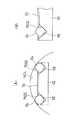
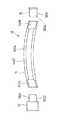
一方、図20に示すように、感光体ドラム12は、筒体1402の表面に感光層1404が形成されたドラム本体14と、ドラム本体14の両端に配設されるフランジ部材16、18とで構成されており、フランジ部材16,18の配設は、フランジ部材16,18の環板部1602,1802がドラム本体14の両端の嵌合穴1406に嵌め込まれ固定されることでなされている。そして、感光体ドラム12の配設は、フランジ部材16,18の軸受部1604、1804がフレーム側で回転可能に支持されることでなされている。なお、フランジ部材16,18の軸受部1604、1804が軸状である場合にはフレームの軸受穴で回転可能に支持され、あるいは、軸受部が穴状である場合にはフレーム側の軸で回転可能に支持されることになる。
前記ドラム本体14を構成する筒体1402は、多くの場合アルミ合金製であり、素材の偏肉や曲がりを合わせて数十ミクロンの振れ回りが既に存在しており、また、筒体1402各部位で微妙な内部応力差が存在するなどしていることから、生産性を高めた通常の加工精度では限界がある。
また、このような筒体1402の表面に設けられる感光層1404の厚さも、筒体1402の周方向において均一とは言い難く、厳密にはばらつきを有している。
このようなドラム本体14のさらなる高精度化も可能とは推察されるが、生産性を著しく阻害することから実現性は乏しい。
また、筒体1402の両端の嵌合穴1406も、それらの中心とドラム本体14の外周面とが高精度で一致しているとは限らず、この嵌合穴1406にフランジ部材16,18が固定され、フランジ部材16,18を介してドラム本体14が回転することから、嵌合穴1406の中心とドラム本体14の外周面中心とがずれている場合に振れ回りが生じる。
【0005】
したがって、感光体ドラム12に対する高精度化要求を満たすためには、ドラム本体14にどの程度の振れがあるかを正確に測定し、振れの程度に応じて、振れを補正して使用する、あるいは、不良品として排除するなど何らかの措置を取らなければならない。
そして、この場合、コストの削減化を図るため、ドラム本体14の振れを正確にしかも短時間でどのようにして測定するかが極めて重要な問題となる。
【0006】
本発明は前記事情に鑑み案出されたものであって、本発明の目的は、ドラム本体の振れを正確にしかも短時間で測定できるドラム本体の振れの測定方法を提供することにある。
また、本発明の目的は、前記測定方法を利用することで高精度化要求を満たせる感光体ドラムの製造方法を提供することにある。
【0007】
【課題を解決するための手段】
前記目的を達成するため本発明の感光体ドラムにおけるドラム本体の振れの測定方法は、ドラム本体の各端部の嵌合穴の内周面の2箇所にそれぞれ下方から支持部材を点接触させることで前記ドラム本体を4点で支持し、前記ドラム本体の外周面で前記支持部材が点接触する各端部の嵌合穴の内周面の2箇所を結ぶ2本の母線のうちの1本の母線上に沿った位置に測定点を持つように距離センサを配置し、前記ドラム本体を回転させ、ドラム本体の周方向に間隔をおいた少なくとも3箇所において、前記距離センサにより該距離センサから前記測定点までの距離を計測し、前記計測により得られた計測値に演算処理を施すことで、前記ドラム本体の両端の嵌合穴の中心を結ぶ仮想中心軸に対する前記外周面の偏心量およびその偏心方向を算出することを特徴とする。
また、本発明の感光体ドラムにおけるドラム本体の振れの測定方法は、ドラム本体の各端部の嵌合穴の内周面の2箇所にそれぞれ下方から支持部材を点接触させることで前記ドラム本体を4点で支持し、前記ドラム本体の外周面で前記支持部材が点接触する各端部の嵌合穴の内周面の2箇所を結ぶ2本の母線のうちの1本の母線上に沿った位置に測定点を持つように距離センサを配置し、前記ドラム本体を90度間隔で回転させ、ドラム本体の周方向の4箇所において、前記距離センサにより該距離センサから前記測定点までの距離を計測し、前記計測により得られた計測値に演算処理を施すことで、前記ドラム本体の両端の嵌合穴の中心を結ぶ仮想中心軸に対する前記外周面の偏心量およびその偏心方向を算出し、前記演算処理は、前記仮想中心軸の位置を原点に取り、その原点と4箇所の測定点のうちの1つの測定点を通る直線をx軸とし、その原点と前記1つの測定点の隣に位置する測定点とを通る直線をy軸とした座標系を定義し、前記座標系において、前記距離センサの第1回目の計測における計測値をx1、第2回目の計測における計測値をy1、第3回目の計測における計測値をx2、第4回目の計測における計測値をy2で表し、前記仮想中心軸の位置を始点とし前記ドラム本体の外周面の仮想中心を終点とする偏心ベクトルとして((x1−x2)/2、(y1−y2)/2)を算出することでなされることを特徴とする。
また、本発明の感光体ドラムにおけるドラム本体の振れの測定方法は、ドラム本体の各端部の嵌合穴の内周面の2箇所にそれぞれ下方から支持部材を点接触させることで前記ドラム本体を4点で支持し、前記ドラム本体の外周面で前記支持部材が点接触する各端部の嵌合穴の内周面の2箇所を結ぶ周方向に90度の間隔をおいた2本の母線上に沿った各位置に測定点を持つように2つの距離センサを配置し、前記ドラム本体を180度間隔で回転させ、ドラム本体の周方向の2箇所において、前記2つの距離センサによりそれら2つの距離センサから前記2つ測定点までの距離を同時に計測し、前記計測により得られた計測値に演算処理を施すことで、前記ドラム本体の両端の嵌合穴の中心を結ぶ仮想中心軸に対する前記外周面の偏心量およびその偏心方向を算出し、前記演算処理は、前記仮想中心軸の位置を原点に取り、その原点と一方の距離センサの測定点とを通る直線をx軸とし、その原点と他方の距離センサの測定点とを通る直線をy軸とした座標系を定義し、前記座標系において、前記一方の距離センサの第1回目の計測における計測値をx1、前記他方の距離センサの第1回目の計測における計測値をy1、前記一方の距離センサの第2回目の計測における計測値をx2、前記他方の距離センサの第2回目の計測における計測値をx2で表し、前記仮想中心軸の位置を始点とし前記ドラム本体の外周面の仮想中心を終点とする偏心ベクトルとして((x1−x2)/2、(y1−y2)/2)を算出することでなされることを特徴とする。
また、本発明の感光体ドラムの製造方法は、前記ドラム本体の各端部の嵌合穴の内周面の2箇所にそれぞれ下方から支持部材を点接触させることで前記ドラム本体を4点で支持し、前記ドラム本体の長手方向中央の外周面で前記支持部材が点接触する各端部の嵌合穴の内周面の2箇所を結ぶ2本の母線のうちの1本の母線上に沿った位置に測定点を持つように距離センサを配置し、前記距離センサにより該距離センサから前記測定点までの距離を計測し、このような計測をドラム本体を回転させドラム本体が静止してから、ドラム本体の周方向に間隔をおいた少なくとも3箇所について行ない、前記計測により得られた計測値に演算処理を施すことで、前記ドラム本体の両端の嵌合穴の中心を結ぶ仮想中心軸に対する前記外周面の偏心方向を算出し、前記偏心方向が所定の向きとなるようにドラム本体を回転させ、前記フランジ部材の前記偏心方向を、前記所定の向きに対して前記ドラム本体の偏心量と前記フランジ部材の偏心量とが打ち消し合う向きにしてフランジ部材の環板部を各端部の嵌合穴に嵌め込み固定するようにしたことを特徴とする。
また、本発明の感光体ドラムの製造方法は、前記ドラム本体の各端部の嵌合穴の内周面の2箇所にそれぞれ下方から支持部材を点接触させることで前記ドラム本体を4点で支持し、前記ドラム本体の長手方向中央の外周面で前記支持部材が点接触する各端部の嵌合穴の内周面の2箇所を結ぶ2本の母線上に沿った各位置にそれぞれ測定点を持つように2つの距離センサを配置し、前記ドラム本体が静止した後に、これら2つの距離センサによりこれら2つの距離センサから前記2本の母線上におけるドラム本体の外周面の2箇所までの距離が同時に計測され、次に、ドラム本体を180度回転させドラム本体が静止した後に前記2つの距離センサによりこれら2つの距離センサから前記2箇所とは別のドラム本体の外周面の2箇所までの距離が計測され、前記計測により得られた計測値に演算処理を施すことで、前記ドラム本体の両端の嵌合穴の中心を結ぶ仮想中心軸に対する前記外周面の偏心方向を算出し、前記演算処理は、前記仮想中心軸の位置を原点に取り、その原点と一方の距離センサの測定点とを通る直線をx軸とし、その原点と他方の距離センサの測定点とを通る直線をy軸とした座標系を定義し、前記座標系において、前記一方の距離センサの第1回目の計測における計測値をx1、前記他方の距離センサの第1回目の計測における計測値をy1、前記一方の距離センサの第2回目の計測における計測値をx2、前記他方の距離センサの第2回目の計測における計測値をx2で表し、前記仮想中心軸の位置を始点とし前記ドラム本体の外周面の仮想中心を終点とする偏心ベクトルとして((x1−x2)/2、(y1−y2)/2)を算出することでなされ、前記偏心方向が所定の向きとなるようにドラム本体を回転させ、前記フランジ部材の前記偏心方向を、前記所定の向きに対して前記ドラム本体の偏心量と前記フランジ部材の偏心量とが打ち消し合う向きにしてフランジ部材の環板部を各端部の嵌合穴に嵌め込み固定するようにしたことを特徴とする。
【0008】
本発明のドラム本体の振れの測定方法によれば、計測時にドラム本体を回転させてもドラム本体は速やかに静止状態となり、また、計測操作も少なく、短時間にしかも正確にドラム本体の振れを測定することが可能となる。
また、本発明の感光体ドラムの製造方法によれば、偏心したドラム本体とフランジ部材から、偏心量を小さく抑えて高精度要求を満たす感光体ドラムが簡単に、しかも迅速に得られる。
【0009】
【発明の実施の形態】
以下、本発明に係るドラム本体の振れの測定方法および感光体ドラムの製造方法を装置と共に説明する。
図1(A)は測定装置の正面図、(B)は母線と測定点との関係を示すドラム本体の平面図、図2は測定装置の側面図、図3は測定装置の平面図、図4は支持部の要部の拡大図を示す。
感光体ドラム12を構成するドラム本体14の振れの測定装置20は、基台22と、基台22上に設けられ測定すべきドラム本体14が載置される載置部24と、載置部24の両側に設けられた支持部26と、ドラム本体14の振れを測定する測定部28と備えている。
【0010】
前記載置部24は、基台22上に配設された昇降部30と、昇降部30の両側に設けられた支持壁部32と、支持壁部32で支持された2本の軸部材34と、各軸部材34に取着された支持ローラ36などにより構成されている。
前記昇降部30は、ガイド38を介して水平方向に移動可能に配設された下フレーム40と、下フレーム40上で昇降手段42を介して昇降可能に支持された上フレーム44を備える。
前記ガイド38は、図3に示すように、Y軸方向に平行して延在し、したがって、載置部24はY軸方向に移動可能である。載置部24の移動は、下フレーム40に連結された駆動手段41(図1(A)参照)により行われ、図3に示すように、載置部24は、測定位置(ア)とフランジ圧入位置(イ)との間で移動される。前記駆動手段41や昇降手段42は、例えば、エアシリンダなどを用いて構成されている。
前記両側の支持壁部32は、測定すべきドラム本体14の長さよりも大きな間隔をあけて配置され、前記2本の軸部材34は水平方向で前記ガイド38の延在方向に間隔をおき、前記ガイド38の延在方向と直角な方向(図3に示すX軸方向と平行な方向)に延在しており、2本の軸部材34はこれら支持壁部32によりその両端が回転可能に支持されている。
【0011】
前記両側の支持壁部32のうちの一方の支持壁部32では、これら2本の軸部材34のうちの一方が貫通して配設され、また、一方の支持壁部32には、これら2本の軸部材34とは別の軸部材46が回転可能に配設されている。そして、支持壁部32の外側に突出する軸部材34部分と前記軸部材46部分にそれぞれプーリ48が取着され、両プーリ48にわたりベルト50が掛装されている。
また、上フレーム44上で前記一方の支持壁部32寄りにモータ52が配設され、モータ52の出力軸と前記軸部材46は連結され、モータ52により軸部材46、プーリ48、ベルト50を介して一方の軸部材34が回転するように構成されている。
【0012】
前記支持ローラ36は、図2に示すように、各支持壁部32の内側でそれぞれドラム本体14の長手方向の両端箇所に位置するように合計4つ配設され、それぞれ軸部材34と一体に回転するように配設されている。
前記支持ローラ36は、ゴムなどのような大きな摩擦係数を有し、また、弾性を有する材料で4つとも均一な直径で形成され、その長さは、ドラム本体14の長手方向の両端箇所のみに接触するようにドラム本体14の長さに比べて充分に小さい寸法で形成されている。
また、図1(A)に示すように、各軸部材34の支持ローラ36の間にドラム本体14が載置されるように、各軸部材34の支持ローラ36の外周面間隔は、ドラム本体14の直径よりも小さい寸法となるように配設されている。
【0013】
前記両側の支持部26は、基台22上に設けられた起立壁60と、起立壁60の上部の横壁6002の先端から水平に突出するアーム62と、アーム62の先部に回転可能に配設された2つの球体64などにより構成されている。
前記起立壁60は、ガイド66を介して水平方向に移動可能に配設され、ガイド66は前記Y軸方向と直交するX軸方向に延在している。したがって、支持部26は、図3に示すように、X軸方向に移動可能であり、支持部26のX軸方向に沿った移動は駆動手段61(図2参照)により行われ、両側の支持部26は、測定位置(ウ)と待避位置(エ)との間で移動される。駆動手段61は、例えば、エアシリンダなどにより構成されている。
【0014】
前記横壁6002およびアーム62は、前記支持壁部32の上端よりも上方の箇所で水平方向に延在して設けられている。
前記アーム62は、その先端が嵌合穴1406の上部に挿入されるように、嵌合穴1406の内径よりも小さい幅で、また、嵌合穴1406の内径よりも充分に小さい厚さで形成されている。
図4(A)に断面正面図で、(B)に断面側面図で示すように、アーム62の先端上面には、上方に開放状で上部に至るにつれてその内径が大きくなる凹部68がアーム62の幅方向(Y軸方向)に間隔をおいて2つ形成され、前記球体64は前記凹部68に挿入される。
前記球体64の支持は、球体64を凹部68に挿入した後、アーム62の上面に薄板70を取着し、薄板70に形成された球体64の直径よりも小さい内径の円形孔7002から球体64の上部を薄板70の上方に突出させることで行われ、これにより球体64はアーム62の先部で、抜落不能かつ回転可能に支持されることになる。
【0015】
前記測定部28は、2個の距離センサ2802X、2802Yと、これら距離センサ2802X、2802Yによって得られた計測値に演算処理を施す演算部2804(図2参照)とを備えている。
前記距離センサ2802X、2802Yとしては、例えばレーザ干渉計を利用した高精度の距離センサを用いることができる。2個の距離センサ2802X、2802Yは、図1に示すように、駆動手段2902に連結されたセンサ支持機構2904で支持され、2個の距離センサ2802X、2802Yは、駆動手段2902によりセンサ支持機構2904を介して、下降位置である測定位置(オ)と、上昇位置である待避位置(カ)との間で昇降される。
2個の距離センサ2802X、2802Yは、測定を行うとき以外は待避位置(カ)へ移動され、測定を行うときに測定位置(オ)へ移動される。また、測定位置(オ)に位置している時には、それら距離センサ2802X、2802Yの夫々の測定点が、支持部26で支持されたドラム本体14の外周面上の、長手方向中央付近の、周方向に90度の間隔をおいた2箇所の位置に設定され、また更に、それら測定点2812X、2812Yは、図1(B)に示すように、ドラム本体14の内周面の両端部の各々2箇所ずつの支持点P(球体64が嵌合穴1406の内周面に接触する箇所)の、対応するものどうしを結んだ2本の母線B上に夫々が位置するように設定される。
【0016】
そして、2個の距離センサ2802X、2802Yによって同時に計測を行うことで、夫々の測定点2812X、2812Yにおける、各々の距離センサ2802X、2802Yからドラム本体14の外周面までの距離が同時に計測される。
2個の距離センサ2802X、2802Yからは、夫々の測定値を表すセンサ信号が出力され、それらセンサ信号は演算部2804へ供給されている。
演算部2804は、供給されたセンサ信号をコンピュータが読込可能なディジタル信号に変換する信号変換回路と、変換されたディジタル信号を読込んで処理するコンピュータとで構成されている。コンピュータは、距離センサ2804X、2802Yの測定値に対して所定の演算処理を施すことで、ドラム本体14の仮想中心軸(ドラム本体14の両端の嵌合穴1406の中心を結んだ軸線)に対する外周面の偏心量とその偏心方向とを算出する。この演算処理については後に詳しく説明する。
【0017】
次に、測定装置20によりドラム本体14の振れを測定する手順について説明する。
なお、本実施の形態では、ドラム本体14の振れの測定時、載置部24は測定位置(ア)に位置している。
まず、昇降手段42により上フレーム44を上昇させた状態とし、4つの支持ローラ36を上昇した状態とする。また、駆動手段61により両側の支持部26を待避位置(エ)に位置させ、駆動手段2902により距離センサ2802X、2802Yを待避位置(カ)に位置させる。
次に、上昇した状態にある4つの支持ローラ36の上にドラム本体14を載置させる。このドラム本体14の載置は、測定者が自ら手で行なってもよく、あるいは、機械を用いて自動的に行なってもよい。
4つの支持ローラ36の上にドラム本体14が載置されることで、ドラム本体14の長手方向両端の外周面の下面4箇所が4つの支持ローラ36の上面に接触し、ドラム本体14が支持されることになる。
【0018】
次に、駆動手段61により両側の支持部26を測定位置(ウ)に移動させ、また、駆動手段2902により距離センサ2802X、2802Yを測定位置(オ)に移動させる。
この状態を図5に正面図で、図6に側面図で示す。
支持部26が測定位置(ウ)に移動されると、ドラム本体14の両端の嵌合穴1406の内部に、球体64が嵌合穴1406の内周面に接触することなく嵌合穴1406内にアーム62の先部が挿入される。
次に、昇降手段42により上フレーム44を下降させる。これにより、図1、図2に示すように、ドラム本体14の外周面から各支持ローラ36が離れる。
同時に、ドラム本体14両側の嵌合穴1406の内周面の2箇所にそれぞれアーム62の先端の球体64が点接触し、ドラム本体14は両端の嵌合穴1406、球体64を介して4点で支持されることになる。
この場合、ドラム本体14は、その両端の嵌合穴1406内においてそれぞれ2点支持されているので、速やかに静止した状態となる。
【0019】
この静止状態で、まず、距離センサ2802X、2802Yにより、2つの距離センサ2802X、2802Yからドラム本体14の長手方向中央の外周面上面で周方向に90度の間隔をおいた2箇所までの距離が同時に計測される。
前記距離の計測後、昇降手段42により上フレーム44を上昇させる。これにより4つの支持ローラ36が上昇し、ドラム本体14の長手方向両端の外周面の下面4箇所が4つの支持ローラ36で支持されることになる。同時に、ドラム本体両側の嵌合穴1406の内周面から4つの球体64は離れる。
つぎに、モータ52を駆動し、軸部材46、プーリ48、ベルト50を介して一方の軸部材34を回転駆動させ、ドラム本体14を180度回転させる。
【0020】
つぎに、昇降手段42により上フレーム44を下降させ、前記と同様に、ドラム本体14の外周面から各支持ローラ36を離し、ドラム本体両側の嵌合穴1406の内周面の2箇所にそれぞれアーム62の先端の球体64を点接触させ、ドラム本体14を、その長手方向両端においてそれぞれ嵌合穴1406、球体64を介して2点で支持する。
この場合も、ドラム本体14は、その両端の嵌合穴1406内でそれぞれ2点支持されているので、速やかに静止した状態となる。
そして、前記と同様に、距離センサ2802X、2802Yにより、2つの距離センサ2802X、2802Yからドラム本体14の長手方向中央の外周面上面で周方向に90度の間隔をおいた2箇所までの距離が同時に計測され、これにより、2つの距離センサ2802からドラム本体14の長手方向中央の外周面の上面で周方向に90度の間隔をおいた4箇所までの距離が計測されることになる。
【0021】
そして、4箇所の計測値から、ドラム本体14の外周面の長手方向中央の偏心量とその偏心方向とが算出される。
この算出は次のように行われる。
既述の如く、2個の距離センサ2802X、2802Yの夫々の測定点2812X、2812Yは、ドラム本体14の両端部を各々2箇所ずつで支持している合計4箇所の支持点Pによって規定される90度間隔の2本の母線B上に設定されており、それら2つの測定点2812X、2812Yにおいて同時に計測が行われて2つの計測値が得られる。
また、1回目の測定を行ったならば、ドラム本体14を180度回転させて2回目の測定を行い、それら2回の測定によって合計4つの計測値が得られる。
ここで、演算のための座標系として、ドラム本体14の両端の嵌合穴1406の中心を結ぶ仮想中心軸の位置を原点に取り、その原点と一方の距離センサ2802Xの測定点とを通る直線をx軸とし、その原点と他方の距離センサ2802Yの測定点とを通る直線をy軸とした座標系を定義する。
以上のように定義した座標系において、一方の距離センサ2802Xの第1回目の計測における計測値をx1、第2回目の計測における計測値をx2で表し、他方の距離センサ2802Yの第1回目の計測における計測値をy1、第2回目の計測における計測値をy2で表すならば、ドラム本体14の仮想中心軸の位置を始点として、このドラム本体14の外周面の仮想中心を終点とする偏心ベクトルは、((x1−x2)/2、(y1−y2)/2)として求められる。
距離センサを使用した計測においては、本来、その測定点における外周面の位置が、基準となる支持点からどれほど変位しているかを直接計測することはできず、それは、その計測値に含まれている、基準となる支持点から距離センサまでの距離の成分が未知だからである。しかしながら、以上のように2回の計測を行って、180度間隔の2つの測定点における計測値を求め、それら計測値の差分を取ることによって、基準となる支持点と距離センサとの間の距離の成分が除去されて、それら計測値に含まれていた偏心に起因する成分だけが残されるため、偏心量のx成分とy成分とを算出することができるのである。
【0022】
つぎに、上記の測定方法によりドラム本体14の振れが正確に測定できることを検証する。
まず、図7(A)に正面図で、(B)に(A)のB矢視図で示すように、ドラム本体14の両側の嵌合穴1406に、それぞれVブロック102で支持されたピンゲージ104を挿入してドラム本体14を支持する。
また、ドラム本体14の長手方向中央を挟むように走査型レーザ変位計106を配置する。
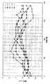
そして、ドラム本体14の長手方向中央でピンゲージ104による支持点を結ぶ母線上において15度おきに合計24点の変位を走査型レーザ変位計106により測定した。測定開始点を0度位置として測定し、その後、ドラム本体14を15度回転させ、静止した後に測定し、以上の作業を繰り返して行なった。
なお、振れの比較を容易にするため、24点の変位平均を取り、平均値が原点となるように数値をオフセットした。
【0023】
ドラム本体14として、加工メーカーの異なる、外径30mm、長さ351mm、端部内径28.6mmのアルマイト管(ドラム1)と、外径30mm、長さ274mm、端部内径28.6mmのアルマイト管(ドラム2)とを、各5本ずつ合計10本(図8に示す1−1乃至1−5の5本と図9に示す2−1乃至2−5の5本との合計10本)使用した。
ピンゲージ104は外径6mmのものを使用した。
走査型レーザ変位計106はキーエンス(株)製の[LSー5040]を使用し、加算回数は768回とした。この条件において、測定時間は640msec、測定精度は±0.3ミクロン以下である。
測定結果を図8、図9に示す。
次に、上記のドラム1とドラム2とを各5本ずつ合計10本(図8に示す1−1乃至1−5の5本と図9に示す2−1乃至2−5の5本との合計10本)について前記実施の形態による測定方法を行ない、図8、図9に示す測定結果と比較することで上記の実施の形態による測定方法の精度について検証する。
【0024】
具体的には、まず、ドラム1本あたりの24点の変位データのうち、90度おきの4点、すなわち、組a(0度、90度、180度、270度)、組b(15度、105度、195度、285度)、組c(30度、120度、210度、300度)、組d(45度、135度、225度、315度)、組e(60度、150度、240度、330度)、組f(75度、165度、255度、345度)の6組の変位データにより、各座標系での偏心ベクトルを計算した。
例えば、組c(30度、120度、210度、300度)の場合、210度位置から30度位置へ向かう方向をX軸、300度位置から120度位置へ向かう方向をY軸とし、30度位置の測定値をX1、120度位置の測定値をY1、210度位置の測定値をX2、300度位置の測定値をY2とすると、偏心ベクトルは(X、Y)座標系で{(X1−X2)/2、(Y1−Y2)/2}として求められる。これを6つの組各々について行なう。
つぎに、X軸を180度位置から0度位置へ向かう方向、Y軸を270度位置から90度位置へ向かう方向に設定し、各座標で求めた6つの偏心ベクトルを(X、Y)座標系に変換することで比較できるようにした。
【0025】
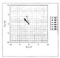
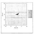
その結果を図10から図19に示す。すなわち、図10から図19に示す測定結果は、図8におけるドラム1−1乃至1−5の5本と図9に示すドラム2−1乃至2−5の5本についての測定結果をそれぞれ示している。
これら図10から図19で明らかなように、10本のドラムの何れにおいても、6個の偏心ベクトルの終点位置、すなわち、測定部位断面円のほぼ中心位置は、半径および1ミクロンの誤差円内に収まっており、十分な精度を持つことが確認された。
また、1本のドラムについて計測操作は2回で済むことから、数秒での処理、例えば5秒以内での処理が可能となる。
したがって、本実施の形態にかかる測定方法によれば、短時間にしかも正確にドラム本体14の振れを測定することが可能となり、高精度要求を満たす感光体ドラムを得る上で極めて有利となる。
【0026】
なお、ドラム本体14の長手方向中央の外周面の偏心量とその偏心方向が算出されたならば、例えば、偏心量の大きさから不良品として排除するか否かを判断したり、あるいは、その偏心方向を考慮して偏心量を小さくするようにドラム本体14に補正加工を施すなどの措置を取るなど任意であるが、本実施の形態では、次のような措置が取られる。
すなわち、ドラム本体14の長手方向中央における偏心量とその偏心方向が算出されたならば、昇降手段42により上フレーム44を上昇させ、ドラム本体14を支持ローラ36で支持させ、嵌合穴1406の内周面から4つの球体64を離す。
つぎに、駆動手段61により両側の支持部26を待避位置(エ)に移動させ、また、駆動手段2902により距離センサ2802を待避位置(カ)に移動させ、モータ52を駆動し、軸部材46、プーリ48、ベルト50を介して一方の軸部材34を回転駆動させ、前記算出された偏心方向が真上(特許請求の範囲の所定の向きに相当)を向くようにドラム本体14を回転させる。
【0027】
つぎに、駆動手段41により載置部24をフランジ圧入位置(イ)に移動させる。
そして、ドラム本体14両側の嵌合穴1406にエアーシリンダなどを用いてフランジ部材16,18を圧入する。
この場合、図20で示すように、フランジ部材16、18は嵌合穴1406に嵌め込まれ固定される環板部1602、1802と、フレーム側で支持される軸受部1604、1804を備えており、フランジ部材16、18は合成樹脂製で型成形されており、環板部1602、1802の中心と軸受部1604、1804との中心とのずれの方向、すなわち偏心方向は金型固有の癖や成形条件により決まることが経験的に判明しているので、例えば、その偏心方向を前記真上とは逆向きの真下にしてドラム本体14の両側の嵌合穴1406にフランジ部材16、18を圧入すれば、ドラム本体14の偏心量とフランジ部材16、18の偏心量とを相殺させ、組み立てられた感光体ドラム12の偏心量(フランジ部材16,18の軸受部1604、1804の中心を結ぶ中心線に対する感光体ドラム12の外周面の偏心量)を小さく抑えることができ、高精度要求を満たすの感光体ドラム12が得られる。
【0028】
なお、本実施の形態では、ドラム本体14の回転時、ドラム本体14を上昇させて嵌合穴1406の内周面から球体64を離すようにしたが、嵌合穴1406の内周面に球体64を接触させた状態でドラム本体14を回転させるようにしてもよい。
また、本実施の形態では嵌合穴1406の内周面の2箇所においてそれぞれ球体64を点接触させるようにしたが、例えば、球体64に代え、摩擦係数の小さい材料からなる突起などを点接触させるようにしてもよい。
また、ドラム本体14の測定箇所は、実施の形態のように4箇所に限定されず、3箇所であってもよく、あるいは、5箇所以上であってもよい。この場合、ドラム本体14の3箇所を測定する場合には、ドラム本体14の長手方向中央の外周面で、支持部材が点接触する両端の嵌合穴の内周面の2箇所を結ぶ2本の母線のうちの1本の母線上に臨むように1つの距離センサを配設し、ドラム本体14を回転させて3回測定すればよい。
なお、N回測定する場合の測定精度を確保するためには、約360度/Nごとに測定点を設け、それぞれの測定点における測定値から偏心ベクトルを求めればよい。
【0029】
本発明において用いる感光体ドラム12は、導電性支持体(筒体1402)上に感光層1404を具備してなるものである。感光層1404は、電荷発生層と電荷輸送層が別に構成されたいわゆる積層型のものと、一つの層からなる単層型のものがあるが、感度等の観点からは積層型の電子写真感光体が好ましい。特に高感度が要求されるフルカラー用の電子写真感光体においては、積層型の電子写真感光体が好適に用いられる。以下、積層型を例に挙げて感光体ドラム12を説明する。
電荷発生層に含有される電荷発生剤としては、セレン及びその合金、ヒ素−セレン、硫化カドミウム、酸化亜鉛、その他の無機光導電体、フタロシアニン類、アゾ系、キナクリドン系、多環キノン系、ペリレン系、インジゴ系、スクアリリウム色素系、アズレニウム色素系、チアピリリウム系、ベンズイミダゾール系などの有機顔料を使用することができる。特に銅、塩化インジウム、塩化カリウム、スズ、オキシチタニウム、亜鉛、バナジウムなどの金属、またはその酸化物や塩化物の配位したフタロシアニン類、無金属フタロシアニン類、または、モノアゾ、ビスアゾ、トリスアゾ、ポリアゾ類などのアゾ顔料が好ましい。これらのうち特にアゾ顔料又はフタロシアニン類がより好ましく、いわゆるY型オキシチタニウムフタロシアニンが高感度を得ることができるため特に好ましい。なお、電荷発生剤は、単独で用いても2種以上を含んで用いても良い。例えば、いわゆるY型オキシチタニウムフタロシアニンと、いわゆるβ型オキシチタニウムフタロシアニンやα型オキシチタニウムフタロシアニンの混合物を電荷発生剤として用いてもよい。
【0030】
いわゆるY型オキシチタニウムフタロシアニンとは、CuKα線によるX線回折においてブラッグ角(2θ±0.2)27.3゜に最大回折ピークを示すものである。この結晶型オキシチタニウムフタロシアニンは、一般にはY型あるいはD型と呼ばれているものであり、例えば特開昭62−67094号公報の第2図(同公報ではII型と称されている)、特開平2−8256号公報の第1図、特開昭64−82045号公報の第1図、電子写真学会誌第92巻(1990年発行)第3号第250〜258頁(同刊行物ではY型と称されている)に示されたものである。この結晶型オキシチタニウムフタロシアニンは、27.3°に最大回折ピークを示すことが特徴であるが、これ以外に通常7.4゜、9.7゜、24.2゜にピークを示す。
なお、回折ピークの強度は、結晶性、試料の配向性及び測定法により変化する場合もあるが、粉末結晶のX線回折を行う場合に通常用いられるブラッグ−ブレンダーノの集中法による測定では、上記のY型オキシチタニウムフタロシアニンは27.3°に最大回折ピークを有する。また、薄膜光学系(一般に薄膜法あるいは平行法とも呼ばれる)により測定された場合には、試料の状態によっては27.3°が最大回折ピークとならない場合があるが、これは結晶粉末が特定の方向に配向しているためと考えられる。
【0031】
電荷発生剤の分散媒としては種々の溶媒を用いてよい。例えば、ジエチルエーテル、ジメトキシエタン、テトラヒドロフラン、1,2−ジメトキシエタン等のエーテル類;アセトン、メチルエチルケトン等のケトン類;酢酸メチル、酢酸エチル等のエステル類;メタノール、エタノール、プロパノール等のアルコール類を単独あるいは2種以上混合して使用することができる。
用いる分散媒の量は分散が充分行え、且つ分散液中に有効量の電荷発生剤が含まれる限りいかなる量でもよく、通常は分散時の分散液中の電荷発生剤の濃度にして3〜20wt%、より好ましくは4〜20wt%程度が好ましい。
電荷発生層に用いられる結着樹脂としてはポリビニルブチラール、ポリビニルアセタール、ポリエステル、ポリカーボネート、ポリスチレン、ポリエステルカーボネート、ポリスルホン、ポリイミド、ポリメチルメタクリレート、フノール樹脂、ブチラール樹脂、ポリ塩化ビニル等のビニル重合体、及びその共重合体、フェノキシ、エポキシ、シリコーン樹脂等またこれらの部分的架橋硬化物等を単独あるいは2種以上用いることができる。
【0032】
結着樹脂と電荷発生剤粒子との混合方法としては例えば、電荷発生剤粒子を分散処理中に結着樹脂を粉末のまま或いはそのポリマー溶液を加え同時に分散する方法、分散液を結着樹脂のポリマー溶液中に混合する方法、或いは逆に分散液中にポリマー溶液を混合する方法等のいずれかの方法を用いてもかまわない。
次にここで得られた分散液は、塗布をするのに適した液物性にするために、種々の溶剤を用いて希釈してもかまわない。このような溶剤としては、例えば前記分散媒として例示した溶媒を使用することができる。電荷発生剤と結着樹脂との割合は特に制限はないが一般には樹脂100重量部に対して電荷発生剤が5〜500重量部の範囲より使用される。
【0033】
電荷移動層に含有される電荷移動剤としては例えば、2,4,7−トリニトロフルオレノン、テトラシアノキシジメタンなどの電子求引性物質、セルバゾール、インドール、イミダゾール、オキサゾール、ピラゾール、オキサジアゾール、ピラゾリン、チアジアゾールなどの複素環化合物、アニリン誘導体、ヒドラゾン化合物、芳香族アミン誘導体、スチルベン誘導体、或いはこれらの化合物からなる基を主鎖もしくは側鎖に有する重合体などの電子供与性物質が挙げられる。電荷移動層についても電荷発生層と同様の結着樹脂等を用いることができる。特に、電荷移動層との相溶性の高い結着樹脂を用いることが好ましい。電荷移動剤と結着樹脂との割合は結着樹脂100重量に対して電荷移動物質が5〜500重量部の範囲により電荷移動層用の分散液が調製される。
【0034】
このようにして調製された分散液を用いて、導電性支持体上に電荷発生層を形成させ、その上に電荷移動層を積層させて感光層1404を形成する。電荷発生層の膜厚は電荷移動層と積層させて感光層1404を形成する場合0.1μm〜10μmの範囲が好適であり、電荷移動層の膜厚は10〜40μmが好適である。
本発明において用いられる電子写真感光体の導電性支持体としては、特に限定されるものではないがアルミニウムまたはアルミニウム合金が好適に使用される。
アルミニウム導電性支持体の材質としては、例えば、JIS1050、JIS1070、JIS1080等の純アルミニウムまたは、AL−Mg系合金、AL−Cu系合金、AL−Si系合金、AL−Mg−Si系合金、AL−Cu−Si系合金等の種々のアルミニウム合金が挙げられ、より好ましくはAL−Mn系合金であるJIS3003、AL−Si系合金であるJIS6063等が挙げられる。なお、本発明において「アルミニウム」という時はアルミニウム合金と分けて表現しない限り、通常、アルミニウム合金も含めた総称を表す。
【0035】
これらのアルミニウム製導電性支持体の製造法は特に限定されないが、アルミニウムビレットをポートホール法、マンドレル法等により押し出し管に加工し、続いて所定の肉厚、外径寸法の円筒とするため、引き抜き加工、インパクト加工、しごき加工、あるいは切削による鏡面加工を行うことで作ることができる。導電性支持体表面には引き抜き油、切削油、防錆油、空気中の各種塵埃等が付着しているため、通常、光導電層を形成する前に洗浄処理が行われる。
公知の方法で製造した導電性支持体は、完全な円筒形状であることは望めず、素材の偏肉や、曲がりを合わせ数μm〜数十μm程度の振れが存在する。この振れをより小さくすることにより電子写真感光体の精度を高めることも考えられる。しかしながら、コストが非常にかかり必ずしも現実的ではない。
導電性支持体と電荷発生層の間には通常使用されるような公知のバリアー層が設けられてもよい。また、感光層1404の外面には、表面保護層が設けられていても良い。
【0036】
バリアー層としては、例えば陽極酸化被膜、酸化アルミニウム、水酸化アルミニウム等の無機層、ポリビニルアルコール、カゼイン、ポリビニルピロリドン、ポリアクリル酸、セルロース類、ゼラチン、デンプン、ポリウレタン、ポリイミド、ポリアミド等の有機層が使用される。バリアー層の膜厚は0.1μm〜20μm、好ましくは0.1μm〜10μmの範囲で使用されるのが最も効果的である。
導電性支持体の上に設けられる電荷発生層、電荷移動層、保護層(以下この欄において「感光層1404」という)の厚さの合計としては、10μm〜50μm程度が好適に設定される。特に、感光層1404が厚い場合には、感光層1404自体のムラが生じやすく本発明がより好適に適用される。このような感光層1404の厚さとしては、20〜50μmが好ましく、25〜50μmであればより好ましく、30〜50μmであれば特に好ましい。
【0037】
本発明の感光体ドラム12を用いた画像形成装置としては、プリンター、複写機、ファクシミリ等があげられる。
本発明の電子写真感光体は、振れが少なく構成されているので、特にフルカラー用のプリンター、複写機、ファクシミリ等に好適に用いることができる。
画像形成装置には、記憶装置▲1▼、記憶装置▲2▼、記憶装置▲3▼、記憶装置▲4▼、ホッパー、スタッカー、記録媒体(用紙)を搬送する搬送路、定着ユニットが設けてある。記憶装置▲1▼〜▲4▼には、それぞれ現像ユニット(帯電器、現像器、定着器、除電器、クリーナ)、電子写真感光体、光学ユニット(露光器)が設けてある。
記録装置▲1▼は、イエロー(以下「Y」という。)の現像ユニットと、電子写真感光体と、光学ユニットを具備する。記録装置▲2▼は、マゼンダ(以下「M」という。)の現像ユニットと電子写真感光体と、光学ユニットを具備する。記録装置▲3▼は、シアン(以下「C」という。)の現像ユニットと電子写真感光体と、光学ユニットを具備する。記録装置▲4▼は、ブラック(以下「K」という)の現像ユニットと、電子写真感光体と、光学ユニットを具備する。
【0038】
ホッパーは、用紙を搬送路に提供するものである。スタッカーは、印刷済みの用紙を積み重ねて保存するものである。搬送路は、用紙を搬送するものである。定着ユニットは、電子写真感光体から用紙に転写された画像を定着するものである。
現像ユニットは、電子写真感光体に形成された潜像に現像材(Y、M、C、Kの各記録装置に対応したトナー)を与えて現像を行うものである。電子写真感光体は、得ようとする画像に応じた静電潜像を作成後、現像ユニットで現像された画像を用紙に転写するものである。光学ユニットは、各画像データ(情報)により変調されたレーザ光で電子写真感光体上を走査して静電潜像を形成するものである。
【0039】
画像形成装置の動作を以下説明する。
コロトロン、ストロコロン等の帯電器を用いて電子写真感光体表面略均一に帯電する。上位コンピュータは、画像、文字等の情報に基づき印刷指令を送る。上位コンピュータからの印刷指令時に、印刷準備が整っていなければ、装置ビズィーを応答し、印刷準備が整っていれば、データ要求を行う。上位コンピュータから、Yデータ、Mデータ、Cデータ、Kデータが送られてくると、画像形成装置の記録装置▲1▼〜▲4▼は、光学ユニットで各色データに対応して変調されたレーザ光で各電子写真感光体上を走査する。これにより、レーザ光が照射された電子写真感光体上の部分は、電荷が除去され、電子写真感光体上に静電潜像が形成される。
【0040】
その後、各現像ユニットで該電子写真感光体に形成された静電潜像にトナー等の現像材を与えて、電子写真感光体上に可視像を形成する。次に、用紙をこの可視像に重ね、用紙の裏から帯電器で現像材とは逆の電荷を用紙に与え、静電力により可視像を用紙に転写する。転写された可視像は、熱又は圧力を加え、用紙に融着させて永久像とする。かかる作業を一つの用紙に対してY、M、C、Kの各色毎に行い、用紙上にカラー画像を得る。一方、転写後の電子写真感光体上の潜像電荷は、光により除電される。また、転写されずに残った残留トナー等の現像材は、クリーナにより除去する。上記、プロセスを繰り返すことにより、連続的に画像形成を行う。
【0041】
また、用紙がホッパーで一枚ずつ搬送路におくられ、ベルト状の搬送手段で用紙が搬送される間に電子写真感光体に掲載された各色の現像済みの像を順次用紙に転写していき、定着ユニットで用紙に転写された像を定着し、最後に、スタッカーで印刷済みの用紙を積み重ねて手保管する。
なお、画像形成装置としては、各電子写真感光体上に付着した現像材(各色トナー)を、一端一つの中間転写ベルトに転写し、中間転写ベルト上で各色のトナーを合わせ、カラー可視像とした後、転写手段を用いて用紙に画像を形成するものであっても良い。
【0042】
【発明の効果】
以上の説明で明らかなように、本発明のドラム本体の振れの測定方法によれば、計測操作も少なく、短時間にしかも正確にドラム本体の振れを測定することが可能となり、したがって、コストの削減化を図りつつ高精度化要求を満たす感光体ドラムを得る上で極めて有利となる。
また、本発明の感光体ドラムの製造方法によれば、上記の本発明の測定方法を利用することで、偏心したドラム本体とフランジ部材から、偏心量を小さく抑えて高精度要求を満たす感光体ドラムが簡単にしかも迅速に得ることが可能となる。
【図面の簡単な説明】
【図1】 (A)は測定装置の正面図、(B)は母線と測定点との関係を示すドラム本体の平面図である。
【図2】測定装置の側面図である。
【図3】測定装置の平面図である。
【図4】支持部の要部の拡大図である。
【図5】支持ローラを上昇させた状態の測定装置の正面図である。
【図6】支持ローラを上昇させた状態の測定装置の側面図である。
【図7】Vブロックとピンゲージを用いてドラム本体を支持し、ドラム本体の振れを測定する際の説明図で、(A)は正面図、(B)は(A)のB矢視図である。
【図8】Vブロックとピンゲージを用いてドラム本体を支持し、測定したドラム本体の振れの結果を示す図である。
【図9】Vブロックとピンゲージを用いてドラム本体を支持し、測定したドラム本体の振れの結果を示す図である。
【図10】本発明方法により測定した、図8におけるドラム1−1の振れの結果を示す図である。
【図11】本発明方法により測定した、図8におけるドラム1−2の振れの結果を示す図である。
【図12】本発明方法により測定した、図8におけるドラム1−3の振れの結果を示す図である。
【図13】本発明方法により測定した、図8におけるドラム1−4の振れの結果を示す図である。
【図14】本発明方法により測定した、図8におけるドラム1−5の振れの結果を示す図である。
【図15】本発明方法により測定した、図9におけるドラム2−1の振れの結果を示す図である。
【図16】本発明方法により測定した、図9におけるドラム2−2の振れの結果を示す図である。
【図17】本発明方法により測定した、図9におけるドラム2−3の振れの結果を示す図である。
【図18】本発明方法により測定した、図9におけるドラム2−4の振れの結果を示す図である。
【図19】本発明方法により測定した、図9におけるドラム2−5の振れの結果を示す図である。
【図20】感光体ドラムの説明図である。
【符号の説明】
12 感光体ドラム
14 ドラム本体
1404 嵌合穴
16、18 フランジ部材
20 測定装置
24 載置部
26 支持部
28 測定部
2802X、2802Y 距離センサ
36 支持ローラ
64 球体[0001]
BACKGROUND OF THE INVENTION
The present invention relates to a method for measuring shake of a photosensitive drum used in an electrophotographic apparatus such as a copying machine or a printer, and a method for manufacturing the same.RelatedTo do.
[0002]
[Prior art]
In recent years, the demand for higher accuracy of the photosensitive drum has been increased due to the promotion of high resolution, color, and miniaturization of the electrophotographic apparatus.
That is, if the photosensitive drum is bent (the photosensitive drum itself is curved) or has an axial deviation (the center of the outer peripheral surface of the photosensitive drum is shifted from the rotation center), the bending or axial deviation is caused. Due to this swinging, an image shift from a position where it should originally be formed occurs during electrostatic latent image formation and transfer.
More specifically, in the case of performing laser scanning using a polygon mirror such as a laser beam printer, when forming an electrostatic latent image, the laser beam is incident obliquely toward the end of the photosensitive drum. If the photosensitive drum is bent or misaligned, a main scanning direction misalignment occurs in which the laser beam arrival position deviates in the drum axis direction. If the photosensitive drum is bent or misaligned, the distance from the rotation center of the photosensitive drum to the surface of the photosensitive drum, that is, the difference in the rotation radius, the exposure of the surface of the photosensitive drum at a portion with a small rotation radius. The moving speed with respect to the system becomes slow and the electrostatic latent image is clogged, and at a portion having a large rotation radius, the moving speed with respect to the exposure system on the surface of the photosensitive drum becomes faster and the sub-scanning direction shift in which the electrostatic latent image extends is generated.
[0003]
As a result, the printed image is distorted. In particular, in the case of a color copying machine called a tandem type that uses a plurality of photosensitive drums arranged in parallel, the positional deviation and the color deviation become prominent.
In addition, when a light emitting diode is used as an exposure apparatus, the focal length is short, so that the image blur due to shaking is likely to occur, and there is a serious problem.
For these reasons, it is necessary to improve the accuracy of the photosensitive drum, particularly to improve the rotational accuracy.
[0004]
[Problems to be solved by the invention]
On the other hand, as shown in FIG. 20, the
The
In addition, the thickness of the
Although it is speculated that such a
In addition, the
[0005]
Therefore, in order to satisfy the high accuracy requirement for the
In this case, in order to reduce the cost, how to measure the shake of the
[0006]
The present invention has been devised in view of the above circumstances, and an object of the present invention is to provide a drum body shake measuring method capable of measuring the shake of the drum body accurately and in a short time.
It is another object of the present invention to provide a method for manufacturing a photosensitive drum that can satisfy the demand for higher accuracy by using the measurement method.The
[0007]
[Means for Solving the Problems]
In order to achieve the above object, the method of measuring the deflection of the drum main body in the photosensitive drum according to the present invention includes bringing the support member into point contact from below at two locations on the inner peripheral surface of the fitting hole at each end of the drum main body. The drum main body is supported at four points, and one of the two busbars connecting two locations on the inner peripheral surface of the fitting hole at each end where the support member makes point contact with the outer peripheral surface of the drum main body. A distance sensor is arranged so as to have a measurement point at a position along the generatrix, and the drum main body is rotated. At least three positions spaced in the circumferential direction of the drum main body are separated from the distance sensor by the distance sensor. By measuring the distance to the measurement point and performing arithmetic processing on the measurement value obtained by the measurement, the eccentric amount of the outer peripheral surface with respect to the virtual center axis connecting the centers of the fitting holes at both ends of the drum body, and Calculate the eccentric direction And wherein the Rukoto.
The drum body shake measuring method for the photosensitive drum according to the present invention is such that the support member is point-contacted from below at two locations on the inner peripheral surface of the fitting hole at each end of the drum body. On one of the two busbars connecting two locations on the inner peripheral surface of the fitting hole at each end where the support member makes point contact with the outer peripheral surface of the drum body. A distance sensor is arranged so as to have measurement points along the position, the drum main body is rotated at intervals of 90 degrees, and the distance sensor from the distance sensor to the measurement point is measured at four positions in the circumferential direction of the drum main body. By measuring the distance and performing arithmetic processing on the measurement value obtained by the measurement, the eccentric amount and the eccentric direction of the outer peripheral surface with respect to the virtual center axis connecting the centers of the fitting holes at both ends of the drum body are calculated. The calculation process is The position of the central axis is taken as the origin, a straight line passing through the origin and one of the four measurement points is taken as the x axis, and the origin and the measurement point located next to the one measurement point are passed. A coordinate system having a straight line as a y-axis is defined. In the coordinate system, the measurement value in the first measurement of the distance sensor is x1, the measurement value in the second measurement is y1, and the measurement value in the third measurement is The value is x2, the measurement value in the fourth measurement is y2, and the eccentricity vector is ((x1-x2) / 2 with the position of the virtual center axis as the start point and the virtual center of the outer peripheral surface of the drum body as the end point. , (Y1-y2) / 2) is calculated.
The drum body shake measuring method for the photosensitive drum according to the present invention is such that the support member is point-contacted from below at two locations on the inner peripheral surface of the fitting hole at each end of the drum body. Are supported at four points, and the drum body is spaced by 90 degrees in the circumferential direction connecting two locations on the inner peripheral surface of the fitting hole at each end where the support member makes point contact with the outer peripheral surface of the drum body. Two distance sensors are arranged so as to have measurement points at respective positions along the generatrix, the drum body is rotated at an interval of 180 degrees, and the two distance sensors are used at two locations in the circumferential direction of the drum body. A virtual central axis that connects the centers of the fitting holes at both ends of the drum body by simultaneously measuring the distances from the two distance sensors to the two measurement points and performing arithmetic processing on the measurement values obtained by the measurement. The amount of eccentricity of the outer peripheral surface with respect to The direction of eccentricity is calculated, and the calculation process takes the position of the virtual central axis as the origin, the straight line passing through the origin and the measurement point of one distance sensor as the x-axis, and the origin and the other distance sensor. A coordinate system having a straight line passing through the measurement point as a y-axis is defined, and in the coordinate system, the measurement value in the first measurement of the one distance sensor is x1, and the first measurement of the other distance sensor is The measured value at y is represented by y1, the measured value at the second measurement of the one distance sensor is represented by x2, the measured value at the second measurement of the other distance sensor is represented by x2, and the position of the virtual central axis is the starting point And ((x1-x2) / 2, (y1-y2) / 2) is calculated as an eccentric vector having an imaginary center of the outer peripheral surface of the drum body as an end point.
Further, in the method of manufacturing the photosensitive drum according to the present invention, the drum body is moved at four points by causing point-contact of the support member from below at two locations on the inner peripheral surface of the fitting hole at each end of the drum body. On one of the two bus bars connecting the two inner peripheral surfaces of the fitting hole at each end where the support member is in point contact with the outer peripheral surface of the drum body in the longitudinal center. A distance sensor is arranged so as to have a measurement point along the position, and the distance sensor measures the distance from the distance sensor to the measurement point, and the drum body is rotated by rotating the drum body. From at least three locations spaced in the circumferential direction of the drum body, and by performing arithmetic processing on the measurement values obtained by the measurement, a virtual central axis that connects the centers of the fitting holes at both ends of the drum body The eccentric direction of the outer peripheral surface with respect to And the drum body is rotated so that the eccentric direction becomes a predetermined direction, and the eccentric direction of the flange member is determined by the eccentric amount of the drum body and the eccentric amount of the flange member with respect to the predetermined direction. The annular plate portion of the flange member is fitted and fixed in the fitting holes at the respective end portions so that they cancel each other out.
Further, in the method of manufacturing the photosensitive drum according to the present invention, the drum body is moved at four points by causing point-contact of the support member from below at two locations on the inner peripheral surface of the fitting hole at each end of the drum body. Measured at each position along two busbars connecting two locations on the inner peripheral surface of the fitting hole at each end where the support member makes point contact with the outer peripheral surface in the longitudinal center of the drum body. Two distance sensors are arranged so as to have a point, and after the drum body is stationary, these two distance sensors are used to connect the two distance sensors to two locations on the outer peripheral surface of the drum body on the two bus bars. The distance is measured at the same time, and then the drum body is rotated 180 degrees and the drum body is stationary, and then the two distance sensors are used to move the two distance sensors to two places on the outer peripheral surface of the drum body different from the two places. Distance of By measuring the measured value obtained by the measurement and performing calculation processing, the eccentric direction of the outer peripheral surface with respect to the virtual center axis connecting the centers of the fitting holes at both ends of the drum body is calculated. , Taking the position of the virtual central axis as the origin, the straight line passing through the origin and the measurement point of one distance sensor as the x-axis, and the straight line passing through the origin and the measurement point of the other distance sensor as the y-axis A coordinate system is defined, and in the coordinate system, the measurement value in the first measurement of the one distance sensor is x1, the measurement value in the first measurement of the other distance sensor is y1, and the one distance sensor The measurement value in the second measurement is represented by x2, the measurement value in the second measurement by the other distance sensor is represented by x2, and the virtual center of the outer peripheral surface of the drum body is defined from the position of the virtual center axis. End point The drum body is rotated by calculating ((x1-x2) / 2, (y1-y2) / 2) as a center vector, and the eccentricity of the flange member is rotated by rotating the drum body so that the eccentric direction is a predetermined direction. The direction of the direction is such that the eccentric amount of the drum body and the eccentric amount of the flange member cancel each other with respect to the predetermined direction, and the annular plate portion of the flange member is fitted into the fitting holes at each end and fixed. It is characterized by that.
[0008]
According to the drum body shake measuring method of the present invention, the drum body quickly becomes stationary even when the drum body is rotated during measurement, and the drum body shake is accurately performed in a short time with few measurement operations. It becomes possible to measure.
In addition, according to the method for manufacturing a photosensitive drum of the present invention, a photosensitive drum satisfying high accuracy requirements can be obtained easily and quickly from an eccentric drum body and a flange member by reducing the amount of eccentricity.The
[0009]
DETAILED DESCRIPTION OF THE INVENTION
A drum body shake measuring method and a photosensitive drum manufacturing method according to the present invention will be described below together with apparatuses.
1A is a front view of the measuring device, FIG. 1B is a plan view of the drum body showing the relationship between the busbars and the measuring points, FIG. 2 is a side view of the measuring device, and FIG. 3 is a plan view of the measuring device. 4 shows an enlarged view of the main part of the support part.
The
[0010]
The
The elevating
As shown in FIG. 3, the
The
[0011]
In one of the
A
[0012]
As shown in FIG. 2, a total of four
The
Further, as shown in FIG. 1A, the interval between the outer peripheral surfaces of the
[0013]
The
The
[0014]
The
The
As shown in a cross-sectional front view in FIG. 4A and a cross-sectional side view in FIG. 4B, a
The
[0015]
The
As the
The two
[0016]
The distances from the
The two
The
[0017]
Next, a procedure for measuring the shake of the
In the present embodiment, when the deflection of the
First, the upper frame 44 is raised by the lifting means 42 and the four
Next, the
Since the
[0018]
Next, the driving means 61 moves the
This state is shown in a front view in FIG. 5 and in a side view in FIG.
When the
Next, the upper frame 44 is lowered by the lifting means 42. Thereby, as shown in FIGS. 1 and 2, the
At the same time, the
In this case, since the drum
[0019]
In this stationary state, first, the
After the distance is measured, the upper frame 44 is raised by the lifting means 42. As a result, the four
Next, the
[0020]
Next, the upper frame 44 is lowered by the elevating
Also in this case, the drum
In the same manner as described above, the
[0021]
Then, the eccentric amount at the center in the longitudinal direction of the outer peripheral surface of the
This calculation is performed as follows.
As described above, the measurement points 2812X and 2812Y of the two
When the first measurement is performed, the drum
Here, as a coordinate system for calculation, the position of the virtual center axis connecting the centers of the
In the coordinate system defined as above, the measurement value in the first measurement of one
In measurement using a distance sensor, it is inherently impossible to directly measure how much the position of the outer peripheral surface at the measurement point is displaced from the reference support point, which is included in the measurement value. This is because the component of the distance from the reference support point to the distance sensor is unknown. However, the measurement is performed twice as described above, the measurement values at two measurement points at intervals of 180 degrees are obtained, and the difference between these measurement values is taken to obtain a difference between the reference support point and the distance sensor. Since the distance component is removed and only the component caused by the eccentricity included in the measurement values is left, the x component and the y component of the eccentricity amount can be calculated.
[0022]
Next, it is verified that the deflection of the
First, as shown in the front view of FIG. 7A and the B arrow view of FIG. 7A, the pin gauges supported by the V blocks 102 in the
Further, the scanning
Then, a total of 24 displacements were measured by a scanning
In order to make it easy to compare the shakes, 24 points were averaged, and the numerical values were offset so that the average value was the origin.
[0023]
As the drum
A
As the scanning
The measurement results are shown in FIGS.
Next, a total of 10
[0024]
Specifically, first, out of 24 points of displacement data per drum, four points every 90 degrees, that is, a set a (0 degrees, 90 degrees, 180 degrees, 270 degrees), a set b (15 degrees) , 105 degrees, 195 degrees, 285 degrees), set c (30 degrees, 120 degrees, 210 degrees, 300 degrees), set d (45 degrees, 135 degrees, 225 degrees, 315 degrees), set e (60 degrees, 150 Eccentric vectors in each coordinate system were calculated from six sets of displacement data of degrees, 240 degrees, 330 degrees) and group f (75 degrees, 165 degrees, 255 degrees, 345 degrees).
For example, in the case of the set c (30 degrees, 120 degrees, 210 degrees, 300 degrees), the direction from the 210 degree position to the 30 degree position is the X axis, and the direction from the 300 degree position to the 120 degree position is the Y axis. If the measured value at the degree position is X1, the measured value at the 120 degree position is Y1, the measured value at the 210 degree position is X2, and the measured value at the 300 degree position is Y2, the eccentric vector is {( X1-X2) / 2, (Y1-Y2) / 2}. This is done for each of the six sets.
Next, the X-axis is set in the direction from the 180-degree position to the 0-degree position, the Y-axis is set in the direction from the 270-degree position to the 90-degree position, and the six eccentric vectors obtained at each coordinate are set to the (X, Y) coordinates. It was made possible to compare by converting to a system.
[0025]
The results are shown in FIGS. That is, the measurement results shown in FIGS. 10 to 19 show the measurement results for the five drums 1-1 to 1-5 in FIG. 8 and the five drums 2-1 to 2-5 shown in FIG. ing.
As is apparent from FIGS. 10 to 19, in any of the ten drums, the end points of the six eccentric vectors, that is, the substantially center position of the measurement site cross-sectional circle are within the error circle of radius and 1 micron. It was confirmed that it has sufficient accuracy.
Further, since the measurement operation for one drum only needs to be performed twice, processing within a few seconds, for example, processing within 5 seconds is possible.
Therefore, according to the measuring method according to the present embodiment, it is possible to measure the shake of the drum
[0026]
If the eccentric amount and the eccentric direction of the outer peripheral surface at the center in the longitudinal direction of the drum
That is, when the eccentric amount and the eccentric direction at the center in the longitudinal direction of the
Next, the support means 26 on both sides is moved to the retracted position (d) by the driving means 61, and the distance sensor 2802 is moved to the retracted position (f) by the driving means 2902 to drive the
[0027]
Next, the mounting
Then, the
In this case, as shown in FIG. 20, the
[0028]
In the present embodiment, when the
In this embodiment, the
Moreover, the measurement location of the drum
In order to ensure the measurement accuracy when measuring N times, it is only necessary to provide measurement points at about 360 degrees / N and obtain the eccentricity vector from the measurement values at each measurement point.
[0029]
The
Examples of the charge generating agent contained in the charge generating layer include selenium and its alloys, arsenic-selenium, cadmium sulfide, zinc oxide, other inorganic photoconductors, phthalocyanines, azo series, quinacridone series, polycyclic quinone series, perylene. Organic pigments such as those based on Indigo, squarylium dyes, azurenium dyes, thiapyrylium dyes, and benzimidazoles can be used. In particular, metals such as copper, indium chloride, potassium chloride, tin, oxytitanium, zinc, vanadium, or phthalocyanines coordinated with oxides or chlorides, metal-free phthalocyanines, or monoazo, bisazo, trisazo, polyazos Azo pigments such as are preferred. Of these, azo pigments or phthalocyanines are more preferable, and so-called Y-type oxytitanium phthalocyanine is particularly preferable because high sensitivity can be obtained. The charge generating agent may be used alone or in combination of two or more. For example, a mixture of so-called Y-type oxytitanium phthalocyanine and so-called β-type oxytitanium phthalocyanine or α-type oxytitanium phthalocyanine may be used as the charge generator.
[0030]
The so-called Y-type oxytitanium phthalocyanine has a maximum diffraction peak at a Bragg angle (2θ ± 0.2) of 27.3 ° in X-ray diffraction by CuKα rays. This crystalline oxytitanium phthalocyanine is generally referred to as Y-type or D-type. For example, FIG. 2 of JP-A-62-67094 (referred to as type II in the same publication), Fig. 1 of JP-A-2-8256, Fig. 1 of JP-A-64-82045, Journal of Electrophotographic Society Vol. 92 (issued in 1990), No. 3, pages 250-258 (in the same publication) (Referred to as Y-type). This crystalline oxytitanium phthalocyanine is characterized by having a maximum diffraction peak at 27.3 °, but normally has peaks at 7.4 °, 9.7 °, and 24.2 °.
The intensity of the diffraction peak may vary depending on the crystallinity, the orientation of the sample, and the measurement method, but in the measurement by the Bragg-Brendano concentration method usually used when performing X-ray diffraction of the powder crystal, The Y-type oxytitanium phthalocyanine has a maximum diffraction peak at 27.3 °. In addition, when measured by a thin film optical system (generally called thin film method or parallel method), 27.3 ° may not be the maximum diffraction peak depending on the state of the sample. This is probably because it is oriented in the direction.
[0031]
Various solvents may be used as a dispersion medium for the charge generating agent. For example, ethers such as diethyl ether, dimethoxyethane, tetrahydrofuran and 1,2-dimethoxyethane; ketones such as acetone and methyl ethyl ketone; esters such as methyl acetate and ethyl acetate; alcohols such as methanol, ethanol and propanol alone Alternatively, two or more kinds can be mixed and used.
The amount of the dispersion medium to be used may be any amount as long as the dispersion can be sufficiently performed and an effective amount of the charge generator is contained in the dispersion, and usually 3 to 20 wt as the concentration of the charge generator in the dispersion at the time of dispersion. %, More preferably about 4 to 20 wt%.
As the binder resin used for the charge generation layer, polyvinyl polymers such as polyvinyl butyral, polyvinyl acetal, polyester, polycarbonate, polystyrene, polyester carbonate, polysulfone, polyimide, polymethyl methacrylate, funol resin, butyral resin, polyvinyl chloride, and the like The copolymer, phenoxy, epoxy, silicone resin, etc., and these partially crosslinked cured products can be used alone or in combination of two or more.
[0032]
As a method for mixing the binder resin and the charge generating particles, for example, a method of dispersing the charge generating particles as a powder or a polymer solution at the same time while dispersing the charge generating particles, or dispersing the dispersion of the binder resin. Any method such as a method of mixing in a polymer solution, or a method of mixing a polymer solution in a dispersion, may be used.
Next, the dispersion obtained here may be diluted with various solvents in order to obtain liquid properties suitable for coating. As such a solvent, the solvent illustrated as the said dispersion medium can be used, for example. The ratio between the charge generating agent and the binder resin is not particularly limited, but generally the charge generating agent is used in the range of 5 to 500 parts by weight with respect to 100 parts by weight of the resin.
[0033]
Examples of the charge transfer agent contained in the charge transfer layer include 2,4,7-trinitrofluorenone, tetracyanoxydimethane and other electron withdrawing substances, selbazole, indole, imidazole, oxazole, pyrazole, oxadiazole. , Electron-donating substances such as heterocyclic compounds such as pyrazoline and thiadiazole, aniline derivatives, hydrazone compounds, aromatic amine derivatives, stilbene derivatives, or polymers having groups composed of these compounds in the main chain or side chain. . For the charge transfer layer, the same binder resin or the like as the charge generation layer can be used. In particular, it is preferable to use a binder resin having high compatibility with the charge transfer layer. The dispersion for the charge transfer layer is prepared so that the ratio of the charge transfer agent to the binder resin ranges from 5 to 500 parts by weight of the charge transfer substance with respect to 100 weight of the binder resin.
[0034]
Using the dispersion prepared as described above, a charge generation layer is formed on a conductive support, and a charge transfer layer is laminated thereon to form a
The conductive support of the electrophotographic photosensitive member used in the present invention is not particularly limited, but aluminum or an aluminum alloy is preferably used.
Examples of the material of the aluminum conductive support include pure aluminum such as JIS1050, JIS1070, and JIS1080, AL-Mg alloy, AL-Cu alloy, AL-Si alloy, AL-Mg-Si alloy, and AL. Examples include various aluminum alloys such as a Cu—Si based alloy, more preferably JIS 3003 which is an AL—Mn based alloy, JIS 6063 which is an AL—Si based alloy, and the like. In the present invention, the term “aluminum” generally represents a general term including an aluminum alloy unless it is expressed separately from an aluminum alloy.
[0035]
Although the manufacturing method of these aluminum conductive supports is not particularly limited, an aluminum billet is processed into an extruded tube by a porthole method, a mandrel method, etc., and then a cylinder having a predetermined thickness and outer diameter is obtained. It can be made by drawing, impacting, ironing, or mirroring by cutting. Since drawing oil, cutting oil, rust preventive oil, various dusts in the air, and the like adhere to the surface of the conductive support, the cleaning treatment is usually performed before the photoconductive layer is formed.
A conductive support manufactured by a known method cannot be expected to be a perfect cylindrical shape, and there is a deviation of several μm to several tens of μm, including uneven thickness of the material and bending. It is also conceivable to increase the accuracy of the electrophotographic photosensitive member by reducing this shake. However, it is very expensive and not always practical.
A known barrier layer as commonly used may be provided between the conductive support and the charge generation layer. A surface protective layer may be provided on the outer surface of the
[0036]
Examples of barrier layers include inorganic layers such as anodized films, aluminum oxide, and aluminum hydroxide, and organic layers such as polyvinyl alcohol, casein, polyvinyl pyrrolidone, polyacrylic acid, celluloses, gelatin, starch, polyurethane, polyimide, and polyamide. used. The barrier layer is most effectively used in the range of 0.1 μm to 20 μm, preferably 0.1 μm to 10 μm.
The total thickness of the charge generation layer, charge transfer layer, and protective layer (hereinafter referred to as “
[0037]
Examples of the image forming apparatus using the
Since the electrophotographic photosensitive member of the present invention is configured with less shake, it can be suitably used particularly for full-color printers, copiers, facsimiles, and the like.
The image forming apparatus includes a storage device (1), a storage device (2), a storage device (3), a storage device (4), a hopper, a stacker, a conveyance path for conveying a recording medium (paper), and a fixing unit. is there. Each of the storage devices {circle around (1)} to {circle around (4)} is provided with a developing unit (charging device, developing device, fixing device, static eliminator, cleaner), electrophotographic photosensitive member, and optical unit (exposure device).
The recording apparatus (1) includes a yellow (hereinafter referred to as “Y”) developing unit, an electrophotographic photosensitive member, and an optical unit. The recording apparatus (2) includes a magenta (hereinafter referred to as “M”) developing unit, an electrophotographic photosensitive member, and an optical unit. The recording apparatus (3) includes a cyan (hereinafter referred to as “C”) developing unit, an electrophotographic photosensitive member, and an optical unit. The recording apparatus (4) includes a black (hereinafter referred to as “K”) developing unit, an electrophotographic photosensitive member, and an optical unit.
[0038]
The hopper provides paper to the conveyance path. The stacker is a stack for storing printed sheets. The conveyance path conveys paper. The fixing unit fixes an image transferred from the electrophotographic photosensitive member to a sheet.
The developing unit applies a developing material (toner corresponding to each recording device of Y, M, C, and K) to the latent image formed on the electrophotographic photosensitive member and performs development. The electrophotographic photosensitive member is to transfer an image developed by the developing unit onto a sheet after creating an electrostatic latent image corresponding to the image to be obtained. The optical unit scans the electrophotographic photosensitive member with a laser beam modulated by each image data (information) to form an electrostatic latent image.
[0039]
The operation of the image forming apparatus will be described below.
The surface of the electrophotographic photosensitive member is charged substantially uniformly using a charger such as corotron or strolocolon. The host computer sends a print command based on information such as images and characters. When printing is instructed from the host computer, if the printer is not ready, it responds with the device busy, and if the printer is ready, it makes a data request. When Y data, M data, C data, and K data are sent from the host computer, the recording devices {circle around (1)} to {circle around (4)} of the image forming apparatus are lasers modulated by the optical unit according to the respective color data. Each electrophotographic photosensitive member is scanned with light. Thereby, the electric charge is removed from the portion on the electrophotographic photosensitive member irradiated with the laser beam, and an electrostatic latent image is formed on the electrophotographic photosensitive member.
[0040]
Thereafter, a developing material such as toner is applied to the electrostatic latent image formed on the electrophotographic photosensitive member in each developing unit to form a visible image on the electrophotographic photosensitive member. Next, the sheet is superimposed on the visible image, a charge opposite to that of the developer is applied to the sheet with a charger from the back of the sheet, and the visible image is transferred to the sheet by electrostatic force. The transferred visible image is fused with heat or pressure to form a permanent image. This operation is performed for each color of Y, M, C, and K on one sheet to obtain a color image on the sheet. On the other hand, the latent image charge on the electrophotographic photosensitive member after transfer is neutralized by light. Further, the developer such as residual toner remaining without being transferred is removed by a cleaner. By repeating the above process, image formation is continuously performed.
[0041]
In addition, the sheets are placed one by one in the conveyance path by the hopper, and the developed images of the respective colors posted on the electrophotographic photosensitive member are sequentially transferred onto the sheets while the sheets are conveyed by the belt-shaped conveyance means. Then, the image transferred on the paper is fixed by the fixing unit, and finally the printed paper is stacked and stored by the stacker.
As an image forming apparatus, a developer (each color toner) attached on each electrophotographic photosensitive member is transferred to one intermediate transfer belt at one end, and each color toner is combined on the intermediate transfer belt. Then, an image may be formed on a sheet using a transfer unit.
[0042]
【The invention's effect】
As is apparent from the above description, according to the drum body shake measuring method of the present invention, it is possible to measure the drum body shake accurately in a short time with less measurement operation. This is extremely advantageous in obtaining a photosensitive drum that satisfies the demand for higher precision while achieving reduction.
Further, according to the method for manufacturing a photoconductor drum of the present invention, by utilizing the measurement method of the present invention described above, the photoconductor that satisfies the high accuracy requirement by reducing the amount of eccentricity from the eccentric drum body and the flange member. The drum can be obtained easily and quickly.The
[Brief description of the drawings]
FIG. 1A is a front view of a measuring apparatus, and FIG. 1B is a plan view of a drum body showing a relationship between a bus bar and measurement points.
FIG. 2 is a side view of the measuring apparatus.
FIG. 3 is a plan view of the measuring apparatus.
FIG. 4 is an enlarged view of a main part of a support part.
FIG. 5 is a front view of the measuring apparatus in a state where the support roller is raised.
FIG. 6 is a side view of the measuring apparatus in a state where the support roller is raised.
FIGS. 7A and 7B are explanatory diagrams when a drum body is supported using a V block and a pin gauge and the deflection of the drum body is measured. FIG. 7A is a front view, and FIG. is there.
FIG. 8 is a diagram showing the result of run-out of the drum body measured by supporting the drum body using a V block and a pin gauge.
FIG. 9 is a diagram showing a result of the vibration of the drum body measured by supporting the drum body using a V block and a pin gauge.
10 is a diagram showing the result of the deflection of the drum 1-1 in FIG. 8 measured by the method of the present invention.
11 is a diagram showing the result of the deflection of the drum 1-2 in FIG. 8 measured by the method of the present invention.
12 is a diagram showing the result of runout of the drum 1-3 in FIG. 8 measured by the method of the present invention.
13 is a diagram showing the result of the deflection of the drum 1-4 in FIG. 8 measured by the method of the present invention.
14 is a diagram showing the result of the deflection of the drum 1-5 in FIG. 8 measured by the method of the present invention.
15 is a diagram showing the result of the deflection of the drum 2-1 in FIG. 9 measured by the method of the present invention.
16 is a diagram showing the result of runout of the drum 2-2 in FIG. 9 measured by the method of the present invention.
17 is a diagram showing the result of runout of the drum 2-3 in FIG. 9 measured by the method of the present invention.
18 is a diagram showing the result of runout of the drum 2-4 in FIG. 9 measured by the method of the present invention.
FIG. 19 is a diagram showing the result of runout of the drum 2-5 in FIG. 9 measured by the method of the present invention.
FIG. 20 is an explanatory diagram of a photosensitive drum.
[Explanation of symbols]
12 Photosensitive drum
14 Drum body
1404 Mating hole
16, 18 Flange member
20 Measuring device
24 Placement part
26 Supporting part
28 Measurement unit
2802X, 2802Y Distance sensor
36 Support roller
64 spheres
Claims (13)
Translated fromJapanese前記ドラム本体の各端部の嵌合穴の内周面の2箇所にそれぞれ下方から支持部材を点接触させることで前記ドラム本体を4点で支持し、
前記ドラム本体の外周面で前記支持部材が点接触する各端部の嵌合穴の内周面の2箇所を結ぶ2本の母線のうちの1本の母線上に沿った位置に測定点を持つように距離センサを配置し、
前記ドラム本体を回転させ、ドラム本体の周方向に間隔をおいた少なくとも3箇所において、前記距離センサにより該距離センサから前記測定点までの距離を計測し、
前記計測により得られた計測値に演算処理を施すことで、前記ドラム本体の両端の嵌合穴の中心を結ぶ仮想中心軸に対する前記外周面の偏心量およびその偏心方向を算出する、
ことを特徴とする感光体ドラムを構成するドラム本体の振れの測定方法。A method for measuring the deflection of the drum body in a photosensitive drum comprising a drum body with fitting holes formed at both ends in the longitudinal direction and a photosensitive layer formed on the outer peripheral surface,
The drum body is supported at four points by making point contact with the supporting member from below at two locations on the inner peripheral surface of the fitting hole at each end of the drum body,
On the outer peripheral surface of the drum main body, the measurement point is located at a position along one of the two bus bars that connects two locations on the inner peripheral surface of the fitting hole at each end where the support member makes point contact. Place the distance sensor to have
Rotating the drum body, measuring the distance from the distance sensor to the measurement point by the distance sensor in at least three places spaced in the circumferential direction of the drum body,
By performing arithmetic processing on the measurement value obtained by the measurement, the eccentric amount of the outer peripheral surface and the eccentric direction thereof with respect to a virtual center axis connecting the centers of the fitting holes at both ends of the drum body are calculated.
A method of measuring a shake of a drum main body constituting a photosensitive drum.
前記ドラム本体の各端部の嵌合穴の内周面の2箇所にそれぞれ下方から支持部材を点接触させることで前記ドラム本体を4点で支持し、 The drum body is supported at four points by making point contact with the supporting member from below at two locations on the inner peripheral surface of the fitting hole at each end of the drum body,
前記ドラム本体の外周面で前記支持部材が点接触する各端部の嵌合穴の内周面の2箇所を結ぶ2本の母線のうちの1本の母線上に沿った位置に測定点を持つように距離センサを配置し、 On the outer peripheral surface of the drum main body, the measurement point is located at a position along one of the two bus bars that connects two locations on the inner peripheral surface of the fitting hole at each end where the support member makes point contact. Place the distance sensor to have
前記ドラム本体を90度間隔で回転させ、ドラム本体の周方向の4箇所において、前記距離センサにより該距離センサから前記測定点までの距離を計測し、 The drum body is rotated at an interval of 90 degrees, and the distance from the distance sensor to the measurement point is measured by the distance sensor at four locations in the circumferential direction of the drum body.
前記計測により得られた計測値に演算処理を施すことで、前記ドラム本体の両端の嵌合穴の中心を結ぶ仮想中心軸に対する前記外周面の偏心量およびその偏心方向を算出し、 By performing arithmetic processing on the measurement value obtained by the measurement, the eccentric amount of the outer peripheral surface and the eccentric direction thereof with respect to the virtual center axis connecting the centers of the fitting holes at both ends of the drum body are calculated,
前記演算処理は、 The arithmetic processing is as follows:
前記仮想中心軸の位置を原点に取り、その原点と4箇所の測定点のうちの1つの測定点を通る直線をx軸とし、その原点と前記1つの測定点の隣に位置する測定点とを通る直線をy軸とした座標系を定義し、 The position of the virtual central axis is taken as the origin, a straight line passing through the origin and one of the four measurement points is taken as the x axis, and the measurement point located next to the origin and the one measurement point Define a coordinate system with the y-axis as the straight line passing through
前記座標系において、前記距離センサの第1回目の計測における計測値をx1、第2回目の計測における計測値をy1、第3回目の計測における計測値をx2、第4回目の計測における計測値をy2で表し、 In the coordinate system, the measurement value in the first measurement of the distance sensor is x1, the measurement value in the second measurement is y1, the measurement value in the third measurement is x2, and the measurement value in the fourth measurement. Is represented by y2,
前記仮想中心軸の位置を始点とし前記ドラム本体の外周面の仮想中心を終点とする偏心ベクトルとして((x1−x2)/2、(y1−y2)/2)を算出することでなされる、 ((X1-x2) / 2, (y1-y2) / 2) is calculated as an eccentric vector starting from the position of the virtual center axis and ending at the virtual center of the outer peripheral surface of the drum body.
ことを特徴とする感光体ドラムを構成するドラム本体の振れの測定方法。 A method of measuring a shake of a drum main body constituting a photosensitive drum.
前記ドラム本体の各端部の嵌合穴の内周面の2箇所にそれぞれ下方から支持部材を点接触させることで前記ドラム本体を4点で支持し、 The drum body is supported at four points by making point contact with the supporting member from below at two locations on the inner peripheral surface of the fitting hole at each end of the drum body,
前記ドラム本体の外周面で前記支持部材が点接触する各端部の嵌合穴の内周面の2箇所を結ぶ周方向に90度の間隔をおいた2本の母線上に沿った各位置に測定点を持つように2つの距離センサを配置し、 Each position along two busbars at intervals of 90 degrees in the circumferential direction connecting two locations on the inner peripheral surface of the fitting hole at each end where the support member makes point contact with the outer peripheral surface of the drum body Place two distance sensors to have a measuring point at
前記ドラム本体を180度間隔で回転させ、ドラム本体の周方向の2箇所において、前記2つの距離センサによりそれら2つの距離センサから前記2つ測定点までの距離を同時に計測し、 The drum body is rotated at an interval of 180 degrees, and at two locations in the circumferential direction of the drum body, the distance from the two distance sensors to the two measurement points is simultaneously measured by the two distance sensors,
前記計測により得られた計測値に演算処理を施すことで、前記ドラム本体の両端の嵌合穴の中心を結ぶ仮想中心軸に対する前記外周面の偏心量およびその偏心方向を算出し、 By performing arithmetic processing on the measurement value obtained by the measurement, the eccentric amount of the outer peripheral surface and the eccentric direction thereof with respect to the virtual center axis connecting the centers of the fitting holes at both ends of the drum body are calculated,
前記演算処理は、 The arithmetic processing is as follows:
前記仮想中心軸の位置を原点に取り、その原点と一方の距離センサの測定点とを通る直線をx軸とし、その原点と他方の距離センサの測定点とを通る直線をy軸とした座標系を定義し、Coordinates taking the position of the virtual central axis as the origin, the straight line passing through the origin and the measurement point of one distance sensor as the x axis, and the straight line passing through the origin and the measurement point of the other distance sensor as the y axis Define the system,
前記座標系において、前記一方の距離センサの第1回目の計測における計測値をx1、前記他方の距離センサの第1回目の計測における計測値をy1、前記一方の距離センサの第2回目の計測における計測値をx2、前記他方の距離センサの第2回目の計測における計測値をx2で表し、 In the coordinate system, the measurement value in the first measurement of the one distance sensor is x1, the measurement value in the first measurement of the other distance sensor is y1, and the second measurement of the one distance sensor is X2 represents the measured value in x, and x2 represents the measured value in the second measurement of the other distance sensor,
前記仮想中心軸の位置を始点とし前記ドラム本体の外周面の仮想中心を終点とする偏心ベクトルとして((x1−x2)/2、(y1−y2)/2)を算出することでなされる、 ((X1-x2) / 2, (y1-y2) / 2) is calculated as an eccentric vector starting from the position of the virtual center axis and ending at the virtual center of the outer peripheral surface of the drum body.
ことを特徴とする感光体ドラムを構成するドラム本体の振れの測定方法。 A method of measuring a shake of a drum main body constituting a photosensitive drum.
前記ドラム本体はその外周面の中心が両端の嵌合穴の中心を結ぶ仮想中心軸から偏心しており、
前記フランジ部材はその環板部中心が軸受部中心から偏心しており、
前記ドラム本体の各端部の嵌合穴の内周面の2箇所にそれぞれ下方から支持部材を点接触させることで前記ドラム本体を4点で支持し、
前記ドラム本体の長手方向中央の外周面で前記支持部材が点接触する各端部の嵌合穴の内周面の2箇所を結ぶ2本の母線のうちの1本の母線上に沿った位置に測定点を持つように距離センサを配置し、
前記距離センサにより該距離センサから前記測定点までの距離を計測し、このような計測をドラム本体を回転させドラム本体が静止してから、ドラム本体の周方向に間隔をおいた少なくとも3箇所について行ない、
前記計測により得られた計測値に演算処理を施すことで、前記ドラム本体の両端の嵌合穴の中心を結ぶ仮想中心軸に対する前記外周面の偏心方向を算出し、
前記偏心方向が所定の向きとなるようにドラム本体を回転させ、
前記フランジ部材の前記偏心方向を、前記所定の向きに対して前記ドラム本体の偏心量と前記フランジ部材の偏心量とが打ち消し合う向きにしてフランジ部材の環板部を各端部の嵌合穴に嵌め込み固定するようにした、
ことを特徴とする感光体ドラムの製造方法。It comprises a drum body having a photosensitive layer formed on the outer peripheral surface and flange members respectively disposed at both ends of the drum body. Each flange member is fitted and fixed in a fitting hole at both ends of the drum body. A method of manufacturing a photosensitive drum having an annular plate portion and a bearing portion,
The drum body is eccentric from the virtual central axis connecting the centers of the fitting holes at both ends of the outer peripheral surface,
The flange member has a center of the ring plate that is eccentric from the center of the bearing,
The drum body is supported at four points by making point contact with the supporting member from below at two locations on the inner peripheral surface of the fitting hole at each end of the drum body,
A position along one of the two busbars connecting two locations of the inner peripheral surface of the fitting hole at each end where the support member makes point contact with the outer peripheral surface in the longitudinal center of the drum body Position the distance sensor so that it has a measuring point at
The distance from the distance sensor to the measurement point is measured by the distance sensor, and such measurement is performed for at least three places spaced in the circumferential direction of the drum body after the drum body is rotated and the drum body is stationary. Do,
By performing arithmetic processing on the measurement value obtained by the measurement, the eccentric direction of the outer peripheral surface with respect to the virtual center axis connecting the centers of the fitting holes at both ends of the drum body is calculated,
Rotate the drum body so that the eccentric direction is a predetermined direction,
The eccentric direction of the flange member is set so that the eccentric amount of the drum body and the eccentric amount of the flange member cancel each other with respect to the predetermined direction, and the annular plate portion of the flange member is fitted to the fitting hole at each end. So that it fits in and is fixed
A method for manufacturing a photosensitive drum.
前記ドラム本体はその外周面の中心が両端の嵌合穴の中心を結ぶ仮想中心軸から偏心しており、
前記フランジ部材はその環板部中心が軸受部中心から偏心しており、
前記ドラム本体の各端部の嵌合穴の内周面の2箇所にそれぞれ下方から支持部材を点接触させることで前記ドラム本体を4点で支持し、
前記ドラム本体の長手方向中央の外周面で前記支持部材が点接触する各端部の嵌合穴の内周面の2箇所を結ぶ2本の母線上に沿った各位置にそれぞれ測定点を持つように2つの距離センサを配置し、
前記ドラム本体が静止した後に、これら2つの距離センサによりこれら2つの距離センサから前記2本の母線上におけるドラム本体の外周面の2箇所までの距離が同時に計測され、
次に、ドラム本体を180度回転させドラム本体が静止した後に前記2つの距離センサによりこれら2つの距離センサから前記2箇所とは別のドラム本体の外周面の2箇所までの距離が計測され、
前記計測により得られた計測値に演算処理を施すことで、前記ドラム本体の両端の嵌合穴の中心を結ぶ仮想中心軸に対する前記外周面の偏心方向を算出し、
前記演算処理は、
前記仮想中心軸の位置を原点に取り、その原点と一方の距離センサの測定点とを通る直線をx軸とし、その原点と他方の距離センサの測定点とを通る直線をy軸とした座標系を定義し、
前記座標系において、前記一方の距離センサの第1回目の計測における計測値をx1、前記他方の距離センサの第1回目の計測における計測値をy1、前記一方の距離センサの第2回目の計測における計測値をx2、前記他方の距離センサの第2回目の計測における計測値をx2で表し、
前記仮想中心軸の位置を始点とし前記ドラム本体の外周面の仮想中心を終点とする偏心ベクトルとして((x1−x2)/2、(y1−y2)/2)を算出することでなされ、
前記偏心方向が所定の向きとなるようにドラム本体を回転させ、
前記フランジ部材の前記偏心方向を、前記所定の向きに対して前記ドラム本体の偏心量と前記フランジ部材の偏心量とが打ち消し合う向きにしてフランジ部材の環板部を各端部の嵌合穴に嵌め込み固定するようにした、
ことを特徴とする感光体ドラムの製造方法。It comprises a drum body having a photosensitive layer formed on the outer peripheral surface and flange members respectively disposed at both ends of the drum body. Each flange member is fitted and fixed in a fitting hole at both ends of the drum body. A method of manufacturing a photosensitive drum having an annular plate portion and a bearing portion,
The drum body is eccentric from the virtual central axis connecting the centers of the fitting holes at both ends of the outer peripheral surface,
The flange member has a center of the ring plate that is eccentric from the center of the bearing,
The drum body is supported at four points by making point contact with the supporting member from below at two locations on the inner peripheral surface of the fitting hole at each end of the drum body,
A measuring point is provided at each position along two busbars connecting two locations on the inner peripheral surface of the fitting hole at each end where the support member makes point contact with the outer peripheral surface in the longitudinal center of the drum body. Arrange two distance sensors as
After the drum body is stationary, the distances from the two distance sensors to two locations on the outer peripheral surface of the drum body on the two buses are simultaneously measured by the two distance sensors.
Next, after the drum body is rotated 180 degrees and the drum body is stationary, the distance from the two distance sensors to two locations on the outer peripheral surface of the drum body different from the two locations is measured by the two distance sensors.
By performing arithmetic processing on the measurement value obtained by the measurement, the eccentric direction of the outer peripheral surface with respect to the virtual center axis connecting the centers of the fitting holes at both ends of the drum body is calculated,
The arithmetic processing is as follows:
Coordinates taking the position of the virtual central axis as the origin, the straight line passing through the origin and the measurement point of one distance sensor as the x axis, and the straight line passing through the origin and the measurement point of the other distance sensor as the y axis Define the system,
In the coordinate system, the measurement value in the first measurement of the one distance sensor is x1, the measurement value in the first measurement of the other distance sensor is y1, and the second measurement of the one distance sensor is X2 represents the measured value in x, and x2 represents the measured value in the second measurement of the other distance sensor,
It is made by calculating ((x1-x2) / 2, (y1-y2) / 2) as an eccentric vector starting from the position of the virtual center axis and ending at the virtual center of the outer peripheral surface of the drum body,
Rotate the drum body so that the eccentric direction is a predetermined direction,
The eccentric direction of the flange member is set so that the eccentric amount of the drum body and the eccentric amount of the flange member cancel each other with respect to the predetermined direction, and the annular plate portion of the flange member is fitted to the fitting hole at each end. So that it fits in and is fixed
A method for manufacturing a photosensitive drum.
Priority Applications (1)
| Application Number | Priority Date | Filing Date | Title |
|---|---|---|---|
| JP2001148643AJP4623348B2 (en) | 2000-05-26 | 2001-05-18 | Measuring method and manufacturing method of photosensitive drum |
Applications Claiming Priority (3)
| Application Number | Priority Date | Filing Date | Title |
|---|---|---|---|
| JP2000-156113 | 2000-05-26 | ||
| JP2000156113 | 2000-05-26 | ||
| JP2001148643AJP4623348B2 (en) | 2000-05-26 | 2001-05-18 | Measuring method and manufacturing method of photosensitive drum |
Publications (2)
| Publication Number | Publication Date |
|---|---|
| JP2002048530A JP2002048530A (en) | 2002-02-15 |
| JP4623348B2true JP4623348B2 (en) | 2011-02-02 |
Family
ID=26592682
Family Applications (1)
| Application Number | Title | Priority Date | Filing Date |
|---|---|---|---|
| JP2001148643AExpired - Fee RelatedJP4623348B2 (en) | 2000-05-26 | 2001-05-18 | Measuring method and manufacturing method of photosensitive drum |
Country Status (1)
| Country | Link |
|---|---|
| JP (1) | JP4623348B2 (en) |
Families Citing this family (3)
| Publication number | Priority date | Publication date | Assignee | Title |
|---|---|---|---|---|
| JP4655830B2 (en)* | 2005-08-30 | 2011-03-23 | アイシン・エィ・ダブリュ株式会社 | Mounting accuracy judgment device |
| JP4897951B2 (en)* | 2006-03-29 | 2012-03-14 | 古河電気工業株式会社 | Tubular deflection measurement method and apparatus |
| JP5663913B2 (en)* | 2010-03-18 | 2015-02-04 | 富士ゼロックス株式会社 | Developer layer thickness measuring device, developer layer thickness measuring method, and developing device manufacturing method |
Family Cites Families (8)
| Publication number | Priority date | Publication date | Assignee | Title |
|---|---|---|---|---|
| JPS5563709A (en)* | 1978-11-08 | 1980-05-14 | Hitachi Ltd | Measuring method of bending at cylinder body |
| DE3303637C2 (en)* | 1983-02-03 | 1985-03-21 | Wieland-Werke Ag, 7900 Ulm | Device for measuring the cross-sectional dimensions on hollow cylindrical workpieces |
| JPS6190005A (en)* | 1984-10-11 | 1986-05-08 | Nippon Steel Corp | Method for measuring bending of tube rods |
| JPH0434306A (en)* | 1990-05-30 | 1992-02-05 | Toshiba Corp | Pseudo cylindricity measurement method |
| JPH10132552A (en)* | 1996-11-01 | 1998-05-22 | Fuji Xerox Co Ltd | Form characteristic measuring device for cylinder, and manufacture of cylindrical electrophotographic photoreceptor |
| JP2000249540A (en)* | 1999-03-02 | 2000-09-14 | Tokyo Seimitsu Co Ltd | Device and method for measuring shape of cylindrical object |
| JP4720010B2 (en)* | 2000-07-10 | 2011-07-13 | 三菱化学株式会社 | Method for measuring vibration of electrophotographic photosensitive drum, and method for manufacturing electrophotographic photosensitive member using the method |
| JP2002090133A (en)* | 2000-09-18 | 2002-03-27 | Toyota Motor Corp | Shaft measuring device and its measuring method |
- 2001
- 2001-05-18JPJP2001148643Apatent/JP4623348B2/ennot_activeExpired - Fee Related
Also Published As
| Publication number | Publication date |
|---|---|
| JP2002048530A (en) | 2002-02-15 |
Similar Documents
| Publication | Publication Date | Title |
|---|---|---|
| CN101369111B (en) | Photoreceptor drum, method and apparatus for assembling same, and image forming apparatus using same | |
| JP2882210B2 (en) | Electrophotographic photosensitive member, method of manufacturing the photosensitive member, and image correction method using the photosensitive member | |
| JP4623348B2 (en) | Measuring method and manufacturing method of photosensitive drum | |
| JP4743370B2 (en) | Photosensitive drum, method of assembling the same, and image forming apparatus using the same | |
| EP0482903B1 (en) | Conductive cylindrical support for xerography | |
| JP4743368B2 (en) | Photosensitive drum, method of assembling the same, and image forming apparatus using the same | |
| JP4720010B2 (en) | Method for measuring vibration of electrophotographic photosensitive drum, and method for manufacturing electrophotographic photosensitive member using the method | |
| US20230288825A1 (en) | Support for electrophotographic photoreceptor, electrophotographic photoreceptor, photoreceptor unit, process cartridge, and image forming apparatus | |
| JP2018180244A (en) | Electrophotographic photosensitive member, process cartridge, and image forming apparatus | |
| JP2006133817A (en) | Photosensitive drum, method of assembling the same, and image forming apparatus using the same | |
| JP3827198B2 (en) | Photosensitive drum | |
| JP2016126047A (en) | Photoconductor, image forming apparatus, and cartridge | |
| JP3661781B2 (en) | Photosensitive drum flange member, photosensitive drum using the same, and image forming apparatus | |
| JP2005186253A (en) | Cutting method of peripheral surface of cylindrical member, manufacturing method of electrophotographic photosensitive member, manufacturing method of electrophotographic photosensitive member unit, manufacturing method of developer carrier, manufacturing method of developer carrier unit, process cartridge, and electronic Photographic equipment | |
| WO2004051381A1 (en) | Electrophotographic system, process cartridge and electrophotographic photosensitive body unit | |
| JP4427774B2 (en) | Photoconductor drum production method and assembly apparatus | |
| JP2009186672A (en) | Electrophotographic photosensitive member and image forming apparatus equipped with the same | |
| JP4821795B2 (en) | Method for manufacturing substrate for electrophotographic photosensitive member, electrophotographic photosensitive member, and image forming apparatus | |
| JP2003255658A (en) | Photosensitive drum for tandem type color image forming apparatus, method of disposing the same, and tandem type color image forming apparatus | |
| JP2003167361A (en) | Method for manufacturing cylindrical base substance for electrophotographic photoreceptor, cylindrical base substance for electrophotographic photoreceptor, electrophotographic sensitive body, image forming apparatus and process cartridge | |
| JP4595982B2 (en) | Photoconductor drum assembly method, photoconductor drum, and image forming apparatus using the same | |
| JP2007065163A (en) | Electrophotographic photosensitive drum unit manufacturing method, process cartridge, and electrophotographic apparatus | |
| JP3226203B2 (en) | Electrophotographic photoreceptor, electrophotographic image forming method and electrophotographic apparatus | |
| JP2006251233A (en) | Cylindrical substrate for electrophotographic photosensitive member, electrophotographic photosensitive member, shake amount measuring apparatus, and shake amount measuring method | |
| JP2001312194A (en) | Image forming method |
Legal Events
| Date | Code | Title | Description |
|---|---|---|---|
| A621 | Written request for application examination | Free format text:JAPANESE INTERMEDIATE CODE: A621 Effective date:20080502 | |
| A977 | Report on retrieval | Free format text:JAPANESE INTERMEDIATE CODE: A971007 Effective date:20100204 | |
| A131 | Notification of reasons for refusal | Free format text:JAPANESE INTERMEDIATE CODE: A131 Effective date:20100712 | |
| A521 | Request for written amendment filed | Free format text:JAPANESE INTERMEDIATE CODE: A523 Effective date:20100902 | |
| TRDD | Decision of grant or rejection written | ||
| A01 | Written decision to grant a patent or to grant a registration (utility model) | Free format text:JAPANESE INTERMEDIATE CODE: A01 Effective date:20101007 | |
| A01 | Written decision to grant a patent or to grant a registration (utility model) | Free format text:JAPANESE INTERMEDIATE CODE: A01 | |
| A61 | First payment of annual fees (during grant procedure) | Free format text:JAPANESE INTERMEDIATE CODE: A61 Effective date:20101020 | |
| R150 | Certificate of patent or registration of utility model | Free format text:JAPANESE INTERMEDIATE CODE: R150 | |
| FPAY | Renewal fee payment (event date is renewal date of database) | Free format text:PAYMENT UNTIL: 20131112 Year of fee payment:3 | |
| LAPS | Cancellation because of no payment of annual fees |