JP4622876B2 - Indwelling needle device - Google Patents
Indwelling needle deviceDownload PDFInfo
- Publication number
- JP4622876B2 JP4622876B2JP2006031500AJP2006031500AJP4622876B2JP 4622876 B2JP4622876 B2JP 4622876B2JP 2006031500 AJP2006031500 AJP 2006031500AJP 2006031500 AJP2006031500 AJP 2006031500AJP 4622876 B2JP4622876 B2JP 4622876B2
- Authority
- JP
- Japan
- Prior art keywords
- hub
- needle
- end side
- peripheral surface
- shield tube
- Prior art date
- Legal status (The legal status is an assumption and is not a legal conclusion. Google has not performed a legal analysis and makes no representation as to the accuracy of the status listed.)
- Expired - Fee Related
Links
Images


Classifications
- A—HUMAN NECESSITIES
- A61—MEDICAL OR VETERINARY SCIENCE; HYGIENE
- A61M—DEVICES FOR INTRODUCING MEDIA INTO, OR ONTO, THE BODY; DEVICES FOR TRANSDUCING BODY MEDIA OR FOR TAKING MEDIA FROM THE BODY; DEVICES FOR PRODUCING OR ENDING SLEEP OR STUPOR
- A61M25/00—Catheters; Hollow probes
- A61M25/01—Introducing, guiding, advancing, emplacing or holding catheters
- A61M25/06—Body-piercing guide needles or the like
- A61M25/0612—Devices for protecting the needle; Devices to help insertion of the needle, e.g. wings or holders
- A61M25/0637—Butterfly or winged devices, e.g. for facilitating handling or for attachment to the skin
- A—HUMAN NECESSITIES
- A61—MEDICAL OR VETERINARY SCIENCE; HYGIENE
- A61M—DEVICES FOR INTRODUCING MEDIA INTO, OR ONTO, THE BODY; DEVICES FOR TRANSDUCING BODY MEDIA OR FOR TAKING MEDIA FROM THE BODY; DEVICES FOR PRODUCING OR ENDING SLEEP OR STUPOR
- A61M5/00—Devices for bringing media into the body in a subcutaneous, intra-vascular or intramuscular way; Accessories therefor, e.g. filling or cleaning devices, arm-rests
- A61M5/14—Infusion devices, e.g. infusing by gravity; Blood infusion; Accessories therefor
- A61M5/158—Needles for infusions; Accessories therefor, e.g. for inserting infusion needles, or for holding them on the body
- A—HUMAN NECESSITIES
- A61—MEDICAL OR VETERINARY SCIENCE; HYGIENE
- A61M—DEVICES FOR INTRODUCING MEDIA INTO, OR ONTO, THE BODY; DEVICES FOR TRANSDUCING BODY MEDIA OR FOR TAKING MEDIA FROM THE BODY; DEVICES FOR PRODUCING OR ENDING SLEEP OR STUPOR
- A61M25/00—Catheters; Hollow probes
- A—HUMAN NECESSITIES
- A61—MEDICAL OR VETERINARY SCIENCE; HYGIENE
- A61M—DEVICES FOR INTRODUCING MEDIA INTO, OR ONTO, THE BODY; DEVICES FOR TRANSDUCING BODY MEDIA OR FOR TAKING MEDIA FROM THE BODY; DEVICES FOR PRODUCING OR ENDING SLEEP OR STUPOR
- A61M25/00—Catheters; Hollow probes
- A61M25/01—Introducing, guiding, advancing, emplacing or holding catheters
- A61M25/06—Body-piercing guide needles or the like
- A61M25/0606—"Over-the-needle" catheter assemblies, e.g. I.V. catheters
- A—HUMAN NECESSITIES
- A61—MEDICAL OR VETERINARY SCIENCE; HYGIENE
- A61M—DEVICES FOR INTRODUCING MEDIA INTO, OR ONTO, THE BODY; DEVICES FOR TRANSDUCING BODY MEDIA OR FOR TAKING MEDIA FROM THE BODY; DEVICES FOR PRODUCING OR ENDING SLEEP OR STUPOR
- A61M25/00—Catheters; Hollow probes
- A61M25/01—Introducing, guiding, advancing, emplacing or holding catheters
- A61M25/06—Body-piercing guide needles or the like
- A61M25/0612—Devices for protecting the needle; Devices to help insertion of the needle, e.g. wings or holders
- A61M25/0631—Devices for protecting the needle; Devices to help insertion of the needle, e.g. wings or holders having means for fully covering the needle after its withdrawal, e.g. needle being withdrawn inside the handle or a cover being advanced over the needle
- A—HUMAN NECESSITIES
- A61—MEDICAL OR VETERINARY SCIENCE; HYGIENE
- A61M—DEVICES FOR INTRODUCING MEDIA INTO, OR ONTO, THE BODY; DEVICES FOR TRANSDUCING BODY MEDIA OR FOR TAKING MEDIA FROM THE BODY; DEVICES FOR PRODUCING OR ENDING SLEEP OR STUPOR
- A61M5/00—Devices for bringing media into the body in a subcutaneous, intra-vascular or intramuscular way; Accessories therefor, e.g. filling or cleaning devices, arm-rests
- A61M5/178—Syringes
- A61M5/31—Details
- A61M5/32—Needles; Details of needles pertaining to their connection with syringe or hub; Accessories for bringing the needle into, or holding the needle on, the body; Devices for protection of needles
- A61M5/3205—Apparatus for removing or disposing of used needles or syringes, e.g. containers; Means for protection against accidental injuries from used needles
- A61M5/321—Means for protection against accidental injuries by used needles
- A61M5/3243—Means for protection against accidental injuries by used needles being axially-extensible, e.g. protective sleeves coaxially slidable on the syringe barrel
Landscapes
- Health & Medical Sciences (AREA)
- Life Sciences & Earth Sciences (AREA)
- Animal Behavior & Ethology (AREA)
- General Health & Medical Sciences (AREA)
- Biomedical Technology (AREA)
- Heart & Thoracic Surgery (AREA)
- Hematology (AREA)
- Engineering & Computer Science (AREA)
- Veterinary Medicine (AREA)
- Anesthesiology (AREA)
- Public Health (AREA)
- Biophysics (AREA)
- Pulmonology (AREA)
- Vascular Medicine (AREA)
- Infusion, Injection, And Reservoir Apparatuses (AREA)
- Media Introduction/Drainage Providing Device (AREA)
Description
Translated fromJapanese本発明は、軟質の外針と硬質の内針を備え、外針から突出させた内針により穿刺した後に、内針を外針から引き込むことが可能なように構成された誤穿刺防止機能を有する留置針装置に関する。 The present invention has an erroneous puncture prevention function configured to include a soft outer needle and a hard inner needle so that the inner needle can be pulled from the outer needle after puncturing with the inner needle protruding from the outer needle. The present invention relates to an indwelling needle device.
留置針装置は、輸液や輸血、体外血液循環等の処置の際に広く使用され、種々の構成例が知られている。例えば翼付の留置針は、針管が翼部を有するハブの先端部に保持され、ハブの後端部に輸液用チューブが接続される。輸液を行う時には、翼部を患者の腕等に接着テープ等により固定して、針管の穿刺状態を保持する。 Indwelling needle devices are widely used in the treatment of infusion, blood transfusion, extracorporeal blood circulation, and the like, and various configuration examples are known. For example, in an indwelling needle with a wing, a needle tube is held at a distal end portion of a hub having a wing portion, and an infusion tube is connected to a rear end portion of the hub. When performing infusion, the wing is fixed to the patient's arm or the like with adhesive tape or the like, and the puncture state of the needle tube is maintained.
一方、医療施設において、注射針や穿刺針等の誤穿刺による汚染・感染が問題となっている。従って誤穿刺事故を防止するために、翼部を有する円筒状のシールドを針管を有するハブに対してスライド可能に設けた構造が知られている。つまり、円筒状シールドをスライドさせることにより、針管が露出した状態と、シールド内に収納された状態とをとることが可能であり、注射針や穿刺針を使用後に廃棄する際には、針管をシールド内にスライドさせて収納可能となっている。 On the other hand, in medical facilities, contamination / infection due to erroneous puncture such as injection needles and puncture needles has become a problem. Therefore, in order to prevent accidental punctures, a structure is known in which a cylindrical shield having wings is slidable with respect to a hub having a needle tube. That is, by sliding the cylindrical shield, it is possible to take the state in which the needle tube is exposed and the state in which the needle tube is housed in the shield. It can be slid into the shield and stored.
さらに、金属性の針管を血管内に留置させることにより、血管が損傷を受ける場合があるため、軟質の外針と硬質の内針を備え、外針から突出させた内針により穿刺した後に、内針を外針から引き込むことを可能にした留置針の構造も知られている。また、その場合にも誤穿刺を防止するために、上述のような円筒状シールドと組み合わせて、外針を留置させた状態では、内針を円筒状シールド内に収納することを可能にした構造も知られている。 Furthermore, because the blood vessel may be damaged by leaving the metallic needle tube in the blood vessel, it is provided with a soft outer needle and a hard inner needle, and after puncturing with the inner needle protruding from the outer needle, A structure of an indwelling needle that enables the inner needle to be pulled from the outer needle is also known. Also in this case, in order to prevent erroneous puncture, it is possible to store the inner needle in the cylindrical shield in combination with the cylindrical shield as described above when the outer needle is indwelled. Is also known.
そのような誤穿刺防止用の円筒状シールドを有する二重針構造の留置針では、輸液チューブは内針を保持するハブに接続され、内針を円筒状シールド内に引き込んだ状態では、輸液チューブから外針の内腔に至る流路は、内針の内腔を経由することになる。ところが、内針の内腔は径が小さいため、十分な流量を確保することが困難である。 In such an indwelling needle having a cylindrical shield for preventing erroneous puncture, the infusion tube is connected to a hub that holds the inner needle, and when the inner needle is drawn into the cylindrical shield, the infusion tube The flow path from the inner needle to the inner lumen of the outer needle goes through the inner needle lumen. However, since the lumen of the inner needle has a small diameter, it is difficult to ensure a sufficient flow rate.
そこで流量を確保するため、内針を保持するハブの外周面と円筒状シールドの内周面との間に形成される空間を、内針の内腔が形成する流路に追加される流路として利用することが考えられた。すなわち、ハブの外周面と円筒状シールドの内周面との間に形成される空間が外針と内針の間を通って外針の内腔に連通し、かつ、その空間とハブの内腔とを連通させる開口部をハブに形成した構造が採用される。ハブの内腔は内針の内腔よりも太くすることができるので、全体として、内針の内腔だけの流路に比べて大きな流量を確保することが可能となる(例えば特許文献1を参照)。
しかしながら、上記従来例の留置針装置は、ハブに1個の開口部を形成しただけであり、流量の確保には十分ではない。一方、開口部を大きくし過ぎると、開口部よりも先端側に位置する内針を保持するためのハブ先端部と、その後端部との結合が構造的に弱くなり、安全に使用するために強度を確保できなくなる。また、内針を円筒状シールド内に収納して保持するための機構が、開口部とはまったく別個に設けられると、ハブが軸方向に長くなり、装置全体が大きくなる。 However, the indwelling needle device of the above-described conventional example only has one opening formed in the hub, and is not sufficient for securing the flow rate. On the other hand, if the opening is made too large, the connection between the distal end of the hub and the rear end of the hub for holding the inner needle located on the distal side of the opening is structurally weak, so that it can be used safely. Strength cannot be secured. If the mechanism for storing and holding the inner needle in the cylindrical shield is provided completely separate from the opening, the hub becomes longer in the axial direction and the entire apparatus becomes larger.
本発明は、ハブの内腔に連通する開口部の断面積を十分に確保しながらも、開口部が形成されたハブの側壁と内針を保持するハブ先端部との結合を安定した強固な構造とし、しかもハブをコンパクトに構成可能な留置針装置を提供することを目的とする。 The present invention provides a stable and strong connection between the side wall of the hub in which the opening is formed and the tip of the hub that holds the inner needle, while ensuring a sufficient cross-sectional area of the opening that communicates with the inner cavity of the hub. An object of the present invention is to provide an indwelling needle device having a structure and a hub that can be configured compactly.
本発明の留置針装置は、略円筒状のシールド筒と、前記シールド筒の先端部に固定された軟質の外針と、前記シールド筒の内腔に軸方向に移動可能なように挿入され、その後端に輸液チューブが接続されるハブと、前記ハブの先端部に固定され前記外針の内腔に挿入可能な硬質の内針とを備え、前記ハブが前記シールド筒の内腔の先端部に位置するときに、前記内針は前記外針の内腔を貫通して外部に突出し、前記ハブを前記シールド筒の内腔の後端側へ移動させることにより前記内針を前記シールド筒の内腔に収納可能である。 The indwelling needle device of the present invention is inserted in a substantially cylindrical shield tube, a soft outer needle fixed to the tip of the shield tube, and inserted into the lumen of the shield tube so as to be axially movable. A hub to which an infusion tube is connected at a rear end thereof, and a hard inner needle that is fixed to the distal end portion of the hub and can be inserted into the lumen of the outer needle, the hub being a distal end portion of the lumen of the shield tube The inner needle projects through the lumen of the outer needle to the outside, and moves the hub to the rear end side of the lumen of the shield tube, thereby moving the inner needle to the shield tube. It can be stored in the lumen.
そして、上記課題を解決するために、本発明の第1の構成の留置針装置は、前記ハブにはその外周から内腔に貫通する横貫通路が形成され、前記ハブの外周面と前記シールド筒の内周面との間に形成される空間が、前記横貫通路を介して前記ハブの内腔と連通しており、前記ハブにおける前記横貫通路よりも後端側の外周面に、前記ハブの外周面と前記シールド筒の内周面との間の液密性を保持するための封止部が設けられ、前記ハブにおける前記横貫通路の両側の側壁の外周面に係止凹部が設けられ、前記シールド筒の後端側の内周面に後端側係止凸部が設けられ、前記後端側係止凸部は前記内針が前記シールド筒の内腔に収納された状態において前記係止凹部と係合可能であることを特徴とする。 And in order to solve the above-mentioned subject, in the indwelling needle device of the 1st composition of the present invention, the above-mentioned hub is formed with a transverse penetration way which penetrates from the outer periphery to a lumen, and the outer peripheral surface of said hub and said shield A space formed between the inner peripheral surface of the tube communicates with the inner cavity of the hub via the lateral through passage, and on the outer peripheral surface of the hub on the rear end side of the lateral through passage, A sealing portion is provided to maintain liquid tightness between the outer peripheral surface of the hub and the inner peripheral surface of the shield tube, and a locking recess is formed on the outer peripheral surface of the side wall on both sides of the lateral through-passage in the hub. A rear end side locking projection is provided on the inner peripheral surface of the rear end side of the shield tube, and the rear end side locking projection is configured such that the inner needle is housed in the lumen of the shield tube. It is possible to engage with the locking recess in the state.
本発明の第2の構成の留置針装置は、前記ハブにはその外周から内腔に貫通する横貫通路が形成され、前記ハブの外周面と前記シールド筒の内周面との間に形成される空間が、前記横貫通路を介して前記ハブの内腔と連通しており、前記ハブにおける前記横貫通路よりも後端側の外周面に、前記ハブの外周面と前記シールド筒の内周面との間の液密性を保持するための封止部が設けられ、前記ハブにおける前記横貫通路の両側の側壁の外周面に先端側係止凹部が設けられ、前記ハブの前記封止部よりも後端側の外周面に後端側係止凹部が設けられ、前記シールド筒の先端側の内周面に先端側係止凸部が設けられ、前記先端側係止凸部は前記内針が前記外針から外部に突出した状態で前記ハブの先端側係止凹部と係合可能であり、前記シールド筒の後端側の内周面に後端側係止凸部が設けられ、前記後端側係止凸部は前記内針が前記シールド筒の内腔に収納された状態において前記後端側係止凹部と係合可能であることを特徴とする。 In the indwelling needle device according to the second configuration of the present invention, the hub is formed with a lateral through passage that penetrates from the outer periphery to the inner cavity, and is formed between the outer peripheral surface of the hub and the inner peripheral surface of the shield tube. The space to be communicated with the inner cavity of the hub through the lateral through passage, and the outer peripheral surface of the hub and the shield tube are disposed on the outer peripheral surface of the hub at the rear end side of the lateral through passage. A sealing portion for maintaining liquid tightness with the inner peripheral surface is provided, a distal end side locking recess is provided on the outer peripheral surface of the side wall on both sides of the lateral through passage in the hub, and the hub of the hub A rear end side locking concave portion is provided on the outer peripheral surface on the rear end side of the sealing portion, and a front end side locking convex portion is provided on the inner peripheral surface on the front end side of the shield tube. Is capable of engaging with the front-end-side locking recess of the hub with the inner needle protruding outward from the outer needle, and the shield A rear end side locking convex portion is provided on the inner peripheral surface of the rear end side, and the rear end side locking convex portion is engaged with the rear end side engagement when the inner needle is housed in the lumen of the shield tube. It is possible to engage with the stop recess.
上記構成によれば、先端側係止凹部と横貫通路を軸方向の同一位置に配置し、係止凹部を一対とすることにより、横貫通路により十分な流路断面積を確保しながらも、係止凹部が形成された側壁と、内針を保持するハブの先端部の結合部分を十分に強固で安定した構造とし、しかもハブを極めてコンパクトに構成できる。 According to the above configuration, the front-end-side locking recess and the horizontal through-passage are arranged at the same position in the axial direction, and the locking recess is paired, while ensuring a sufficient flow passage cross-sectional area by the horizontal through-passage. The connecting portion between the side wall in which the locking recess is formed and the tip of the hub that holds the inner needle is sufficiently strong and stable, and the hub can be configured very compactly.
本発明の第1の構成の留置針装置において、前記シールド筒の先端側の内周面に先端側係止凸部が設けられ、先端側係止凸部は前記内針が前記外針から外部に突出した状態で前記ハブの係止凹部と係合可能である構成とすることができる。 In the indwelling needle device of the first configuration of the present invention, a distal end side locking convex portion is provided on an inner peripheral surface of the distal end side of the shield tube, and the inner side needle protrudes from the outer needle to the distal end side locking convex portion. It can be set as the structure which can be engaged with the latching recessed part of the said hub in the state protruded in this.
上記いずれかの構成の留置針装置において、前記ハブにおける前記横貫通路よりも先端側の外径は、後端側の外径よりも小さい構成とすることができる。 In the indwelling needle device having any one of the configurations described above, the outer diameter of the hub on the front end side with respect to the lateral through path may be smaller than the outer diameter on the rear end side.
また、前記先端側係止凸部及び前記後端側係止凸部は、前記シールド筒の内周方向に延びた環状凸部として形成されている構成とすることができる。 Moreover, the front end side locking convex portion and the rear end side locking convex portion may be formed as annular convex portions extending in the inner peripheral direction of the shield tube.
また、前記封止部を、前記ハブの外周面に形成された環状溝と、前記環状溝に装着されたOリングにより構成することができる。 Further, the sealing portion can be constituted by an annular groove formed on the outer peripheral surface of the hub and an O-ring attached to the annular groove.
また、前記ハブの内腔における前記横貫通路と連通する部位よりも後端側の径は、前記内針の内腔の径よりも大きく、前記輸液チューブの内径と同等以下である構成とすることができる。 In addition, the diameter of the rear end side of a portion communicating with the lateral through passage in the lumen of the hub is larger than the diameter of the lumen of the inner needle and is equal to or smaller than the inner diameter of the infusion tube. be able to.
また、前記ハブの外周面に、前記ハブの先端部外周面と前記シールド筒内周面の間に形成される空間と前記横貫通路とを連通させる軸方向溝が形成されている構成とすることができる。 In addition, an axial groove is formed on the outer peripheral surface of the hub so as to communicate the space formed between the outer peripheral surface of the tip end portion of the hub and the inner peripheral surface of the shield cylinder and the lateral through passage. be able to.
また、前記内針は先端部に側孔を有し、前記側孔は、前記外針の先端から前記内針が突出する量が最も大きい状態において前記外針の先端部が前記内針に対して接触する位置よりも後端側に位置する構成とすることができる。 In addition, the inner needle has a side hole at a distal end portion, and the side hole has a distal end portion of the outer needle with respect to the inner needle in a state where the amount of the inner needle protruding from the distal end of the outer needle is the largest. It can be set as the structure located in the back end side rather than the position which touches.
以下に、本発明の実施の形態について、図面を参照して具体的に説明する。 Embodiments of the present invention will be specifically described below with reference to the drawings.
(実施の形態1)
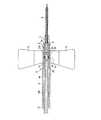
図1は、本発明の実施の形態1における留置針装置の軸方向に沿った断面図である。図2は、同留置針装置の内針を円筒状シールド内に引き込んだ状態を示す断面図である。(Embodiment 1)
FIG. 1 is a cross-sectional view along the axial direction of the indwelling needle device according to Embodiment 1 of the present invention. FIG. 2 is a cross-sectional view showing a state in which the inner needle of the indwelling needle device is pulled into the cylindrical shield.
1は金属製の内針であり、樹脂製の内ハブ2の先端部に固定されている。内ハブ2の後端部にはチューブ3が接続されている。4は翼付きシールドであり、樹脂製の略円筒形状を有するシールド筒4aと、左右の翼部5、6からなる。シールド筒4aの内腔に内針1および内ハブ2が挿入されて、軸方向に移動可能である。左右の翼部5、6は、シールド筒4aの先端部、すなわち内針1が突出する側の端部に設けられている。翼部5、6は、各々シールド筒4aの外周面の両側部に結合し、シールド筒4aの軸を中心として互いに対称な形状を有する。シールド筒4aの材質としては、可撓性を有する樹脂材料、例えば、ポリエチレン、塩化ビニル樹脂、その他のエラストマーを用い、内ハブ2の材質としては、例えばポリカーボネートを用いることができる。 Reference numeral 1 denotes a metal inner needle, which is fixed to the distal end portion of the resin
シールド筒4aの先端部には外ハブ7が固定され、外ハブ7の内腔に外針8が装着されてかしめ部材9により固定されている。外針8の内腔には内針1が挿入され、その先端が外針8から突出している。外針8は、樹脂材料、例えばポリウレタン系エラストマーで形成される。 An outer hub 7 is fixed to the distal end portion of the
内ハブ2は、前部2a、後部2d、およびそれらの間の中間部からなる。後部2dおよび中間部は、シールド筒4aの内腔にちょうど嵌合する程度の外径を有する。前部2aは他の部分よりも径が小さく、後述するように、シールド筒4aの内周面との間に空間が形成される。前部2aの内腔には、内針1が装着されている。後部2dの内腔にはチューブ3が装着されている。中間部における内腔10の径は、内針1の内腔の径よりも大きく、チューブ3の内径と同等か、それよりも小さく設定される。 The
内ハブ2の中間部における外周面には、係止凹部2bと、封止用環状凹部2cが形成されている。また、係止凹部2bと軸方向同位置に横貫通路2eが形成されている。封止用環状凹部2cは、係止凹部2bおよび横貫通路2eよりも後端側に配置され、Oリング11が装着されて封止部を形成している。それにより、内ハブ2の外周面とシールド筒4aの内周面との間の液密性が保持される。シールド筒4aの内周面には、係止凹部2bに対応させて、環状の先端側係止凸部12a、及び環状の後端側係止凸部12bが設けられている。シールド筒4aの後端部の内周面には、環状のストッパー13が形成されている。 A locking
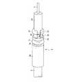
内ハブ2の構造を拡大した斜視図を図3に示す。同図によれば、前部2aの外周面とシールド筒4aの内周面との間の空間が、横貫通路2eを介して内ハブ2の中間部における内腔10と連通している形態が判る。また、横貫通路2eの両側に側壁が一対形成された状態になり、各々の側壁の外周面が窪んで一対の係止凹部2bが形成されている様子も判る。係止凹部2bの先端側には、内ハブ2の中間部の外径を有する径大部2fが形成されている。径大部2fには、前部2aから係止凹部2bに達する軸方向溝16が形成されている。 An enlarged perspective view of the structure of the
図1に示す初期状態では、内針1が外針8から突出して穿刺可能である。この状態では、係止凹部2bと先端側係止凸部12aが係合し、この位置で内ハブ2がシールド筒4aに対して保持されている。また、内ハブ2の前部2aは径が小さいので、外ハブ7の後部内腔に嵌合している。それにより、この初期状態における、内ハブ2の外面とシールド筒4aの内面の間に形成される空間を極小化することができる。この状態で穿刺した後、留置するために、図2に示すように、内針1を外針8から突出しない状態に引き込んだ状態にする。 In the initial state shown in FIG. 1, the inner needle 1 protrudes from the
図2に示す状態では、内ハブ2の前部2aが外ハブ7から脱しているので、径の小さい前部2aの外周面とシールド筒4aの内周面との間に空間14が形成されている。この空間14は、内針1の外周面とシールド筒4aの内周面との間に形成された空間15を介して外針8の内腔に連通している。また、空間14は、軸方向溝16及び横貫通路2eを介して内ハブ2の中間部における内腔10と連通している。これにより、内ハブ2とシールド筒4aの間に形成される空間14が、内針1の内腔が形成する流路に追加される流路として機能するため、より大きな流量を確保することができる。更に、内ハブ2の内腔10は、内針1の内腔よりも太いので、全体として、内針1の内腔だけの流路に比べて大きな流量を確保することができる。 In the state shown in FIG. 2, since the
図2の状態では、係止凹部2bと後端側係止凸部12bが係合することにより、内ハブ2がシールド筒4aに対して保持されている。内針1はシールド筒4a内にほぼ収納されているので、誤穿刺の恐れは十分に軽減される。係止凹部2bと後端側係止凸部12bの係合は、内針1の再突出を防止するために機能する。この状態ではまた、内ハブ2の後端がストッパー13に当接して、内ハブ2がシールド筒4aから外れることを防止する作用が十分に得られる。 In the state of FIG. 2, the
以上のように、係止凹部2bと横貫通路2eを軸方向の同一位置に配置し、係止凹部2bを一対とすることにより、横貫通路2eにより十分な流路断面積を確保しながらも、係止凹部2bが形成された側壁と前部2aの結合部分を十分に強固で安定した構造とすることができる。横貫通路2eを十分に大きくしても、係止凹部2bが形成された側壁が一対であるため、強度的に対称であり、使用に際しての安定性が確保されるからである。また、係止凹部2bと横貫通路2eが軸方向の同一位置に配置されているので、内ハブ2を極めてコンパクトに構成できる。 As described above, the locking
通常、留置針装置は図1の状態で使用に供される。この初期状態では、係止凹部2bと先端側係止凸部12aが係合することにより、内ハブ2がシールド筒4aに対して保持されている。この保持力は、内針1が簡単には後退しない程度の、初期状態を維持するための力である。穿刺操作は、翼部5、6をシールド筒4aの外表面に沿って上方に持ち上げて重ね合わせて把持することにより行う。翼部5、6を把持することにより、把持力がシールド筒4aに伝達され、シールド筒4aが押圧され変形する。それにより、シールド筒4aの内周面と内ハブ2の摩擦接触を介して、内針1が十分な力で保持される。更に、係止凹部2bと先端側係止凸部12aの係合による保持力が増大するため、内針1が十分な力で保持され、穿刺操作を確実に行うことが可能である。 Usually, the indwelling needle device is used in the state shown in FIG. In this initial state, the
穿刺後に留置するためには、チューブ3を介して内ハブ2をシールド筒4aの内部に引き込む力を加え、図2に示す状態にする。すなわち、係止凹部2bと先端側係止凸部12aの係合を解除し、係止凹部2bと後端側係止凸部12bを係合させる。それにより、内針1が血管から引き抜かれ、外針8のみが穿刺された状態で留置される。 In order to place it after puncturing, a force for pulling the
また、穿刺用後に留置針装置を廃棄する際には、図2の状態であれば、誤穿刺を防止できる。つまり、内針1がシールド筒4a内に収納され、係止凹部2bと後端側係止凸部12bの係合により、内針1が再突出することが阻止された状態になっているからである。 Further, when the indwelling needle device is discarded after puncturing, erroneous puncturing can be prevented as long as the state shown in FIG. That is, the inner needle 1 is housed in the
(実施の形態2)
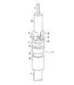
実施の形態2における留置針装置について、図4〜6を参照して説明する。なお、実施の形態1と同一の要素については同一の参照符号を付して、説明の重複を省略する。(Embodiment 2)
The indwelling needle apparatus in
本実施の形態においては、図4に示されるように、内ハブ2の後部2d、従って封止用環状凹部2cよりも後端側の内ハブ2の外周面に、後端側係止凹部2gが設けられている。以降の説明では区別の明確性を考慮して、係止凹部2bを先端側係止凹部2bと称する。後端側係止凹部2gは、内ハブ2の外周面の周方向の溝状に形成されている。 In the present embodiment, as shown in FIG. 4, the rear end
図5に示すように、シールド筒4aの後端側の内周面に設けられた後端側係止凸部12cは、後端側係止凹部2gに対応し、従って、実施の形態1における後端側係止凸部12bに比べて、後端側に寄った位置に形成されている。 As shown in FIG. 5, the rear end side locking
図5に示す留置針装置の状態は、実施の形態1の場合の図1に示した使用(初期)状態と同様である。すなわち、内針1が外針8から突出して穿刺可能であり、先端側係止凹部2bと先端側係止凸部12aが係合し、この位置で内ハブ2がシールド筒4aに対して保持されている。 The state of the indwelling needle device shown in FIG. 5 is the same as the use (initial) state shown in FIG. 1 in the case of the first embodiment. That is, the inner needle 1 protrudes from the
図6に示す状態は、実施の形態1における図2に示した状態に対応し、内針1がシールド筒4a内に収納され状態を示す。但し、実施の形態1と異なり、後端側係止凹部2gと後端側係止凸部12cが係合することにより、内ハブ2がシールド筒4aに対して保持される。この状態での保持のために後端側係止凹部2gを設けた理由は、以下のとおりである。 The state shown in FIG. 6 corresponds to the state shown in FIG. 2 in the first embodiment, and shows a state in which the inner needle 1 is housed in the
実施の形態1では、係止凹部2bの位置が、封止用環状凹部2cよりも先端側(内針1側)に設けられている。この態様の場合、内ハブ2を後退させ、内針1を収納する操作の際に、Oリング11がシールド筒4aの内腔面に設けられた後端側係止凸部12bと物理的に接触することになる。これによって、Oリング11が捩れたり、まくれたりする可能性があり、これが原因で空間15の気密性が確保できなくなる可能性がある。また、収納操作時に物理的な接触の触感により、誤操作を招く可能性もある。 In Embodiment 1, the position of the
これに対して、本実施の形態のように、内ハブ2がシールド筒4a内部の先端側に位置するとき(内針1突出時)には、先端側係止凹部2bと先端側係止凸部12aが係合し、内ハブ2がシールド筒4a内部の後端側に位置するとき(内針1収納時)には、後端側係止凹部2gと後端側係止凸部12cが係合する構造にすれば、上述のようなOリング11と後端側係止凸部12cとの接触が回避される。 On the other hand, when the
(実施の形態3)
実施の形態3における留置針装置について、図7A〜7Cを参照して説明する。本実施の形態は、内針1の改良に関するものである。(Embodiment 3)
An indwelling needle device according to Embodiment 3 will be described with reference to FIGS. The present embodiment relates to an improvement of the inner needle 1.
図7A、7Bに示すように、内針1は、先端部に側孔1aを有する。側孔1aの位置は、図7Cに示すように、外針8との関係を考慮して設定される。すなわち、外針8の先端から内針1が突出する量が最も大きい状態において、外針8の先端部が内針1に対して接触する位置よりも後端側に位置するするように側孔1aが形成される。このように側孔1aを設ける理由は、以下のとおりである。 As shown in FIGS. 7A and 7B, the inner needle 1 has a
すなわち、留置針装置内部を生理食塩水などで充填する「プライミング操作」を実施する際には、内ハブ2がシールド筒4a内部の先端側に位置する初期状態で行う。ところが、側孔1aが設けられていない場合、外針8の内面と内針1の外面との間に形成される空間、及び横貫通路2eよりも先端側のシールド筒4aの内面と内ハブ2の外面とで形成される空間は、プライミングが困難であり、空気が残留し易い。何故ならば、外針8の先端内面と内針1の外面とは密着しており、空気が抜け難いからである。その結果、内針1収納時に装置内部に空気が残留し、この空気が患者の血管内に混入するおそれがある。 That is, when the “priming operation” for filling the indwelling needle device with physiological saline or the like is performed, it is performed in an initial state where the
これに対して、本実施の形態の構成によれば、側孔1aを通じて、外針8の内面と内針1の外面との間に形成される空間、及び横貫通路2eよりも先端側のシールド筒4aの内面と内ハブ2の外面とで形成される空間にも、プライミング用の液体を容易に流入させることができ、留置針装置内部に空気が残留することを防止することができる。この効果をより十分に得るために、側孔1aを複数個設けてもよい。但し、その場合は強度的な問題を考慮する必要がある。 On the other hand, according to the configuration of the present embodiment, the space formed between the inner surface of the
なお、側孔1aを内針1と外針8の先端部との接触位置と同じ位置に設けた態様でも、同様の効果を達成可能である。しかしながら、内針1収納時に側孔1aの縁部で外針8の先端部をめくってしまう可能性があるので、不都合な場合がある。 The same effect can be achieved even in a mode in which the
本発明の留置針装置は、内針と外針の二重構造における、外針から輸液用チューブへの十分な流路断面積を確保しながらも、開口部が形成されたハブの側壁と内針を保持するハブ先端部との結合を安定した強固な構造であり、しかもハブをコンパクトに構成可能なため、輸液や輸血、体外血液循環等の処置に用いるために好適である。 The indwelling needle device according to the present invention has a double structure of an inner needle and an outer needle, while ensuring a sufficient flow path cross-sectional area from the outer needle to the infusion tube, while the hub side wall and inner Since the hub has a stable and stable structure with the hub holding the needle, and the hub can be configured compactly, it is suitable for use in treatments such as infusion, blood transfusion, and extracorporeal blood circulation.
1 内針
1a 側孔
2 ハブ
2a 前部
2b 係止凹部(先端側係止凹部)
2c 封止用環状凹部
2d 後部
2e 横貫通路
3 チューブ
4 翼付きシールド
4a シールド筒
5、6 翼部
7 外ハブ
8 外針
9 かしめ部材
10 内腔
11 Oリング
12a 先端側係止凸部
12b 後端側係止凸部
13 ストッパー
14、15 空間
16 軸方向溝DESCRIPTION OF SYMBOLS 1
Claims (8)
Translated fromJapanese前記シールド筒の先端部に固定された軟質の外針と、
前記シールド筒の内腔に軸方向に移動可能なように挿入され、その後端に輸液チューブが接続されるハブと、
前記ハブの先端部に固定され前記外針の内腔に挿入可能な硬質の内針とを備え、
前記ハブが前記シールド筒の内腔の先端部に位置するときに、前記内針は前記外針の内腔を貫通して外部に突出し、前記ハブを前記シールド筒の内腔の後端側へ移動させることにより前記内針を前記シールド筒の内腔に収納可能である留置針装置において、
前記ハブにはその外周から内腔に貫通する横貫通路が形成され、前記ハブの外周面と前記シールド筒の内周面との間に形成される空間が、前記横貫通路を介して前記ハブの内腔と連通しており、
前記ハブにおける前記横貫通路よりも後端側の外周面に、前記ハブの外周面と前記シールド筒の内周面との間の液密性を保持するための封止部が設けられ、
前記ハブにおける前記横貫通路の両側の側壁の外周面に係止凹部が設けられ、
前記シールド筒の後端側の内周面に後端側係止凸部が設けられ、前記後端側係止凸部は前記内針が前記シールド筒の内腔に収納された状態において前記係止凹部と係合可能であり、
前記シールド筒の先端側の内周面に先端側係止凸部が設けられ、先端側係止凸部は前記内針が前記外針から外部に突出した状態で前記ハブの係止凹部と係合可能であることを特徴とする留置針装置。A substantially cylindrical shield tube;
A soft outer needle fixed to the tip of the shield tube;
A hub inserted in the lumen of the shield tube so as to be movable in the axial direction, and an infusion tube connected to the rear end thereof;
A hard inner needle fixed to the distal end of the hub and insertable into the lumen of the outer needle,
When the hub is positioned at the distal end of the lumen of the shield tube, the inner needle penetrates the lumen of the outer needle and protrudes to the outside, and the hub is moved to the rear end side of the lumen of the shield tube. In the indwelling needle device that can be accommodated in the lumen of the shield tube by moving,
The hub is formed with a horizontal through passage that penetrates from the outer periphery to the inner cavity, and a space formed between the outer peripheral surface of the hub and the inner peripheral surface of the shield tube is formed through the horizontal through passage. Communicates with the hub lumen,
On the outer peripheral surface on the rear end side of the lateral through-passage in the hub, a sealing portion for maintaining liquid tightness between the outer peripheral surface of the hub and the inner peripheral surface of the shield tube is provided,
A locking recess is provided on the outer peripheral surface of the side wall on both sides of the lateral through passage in the hub,
A rear end side locking projection is provided on the inner peripheral surface of the shield tube at the rear end side, and the rear end side locking projection is in the state where the inner needle is housed in the lumen of the shield tube. Can engage with the stop recess,
A tip side locking projection is provided on the inner peripheral surface of the tip side of the shield tube, and the tip side locking projection is engaged with the locking recess of the hub in a state where the inner needle protrudes outside from the outer needle. An indwelling needle device characterized by beingcapable of being combined .
前記シールド筒の先端部に固定された軟質の外針と、
前記シールド筒の内腔に軸方向に移動可能なように挿入され、その後端に輸液チューブが接続されるハブと、
前記ハブの先端部に固定され前記外針の内腔に挿入可能な硬質の内針とを備え、
前記ハブが前記シールド筒の内腔の先端部に位置するときに、前記内針は前記外針の内腔を貫通して外部に突出し、前記ハブを前記シールド筒の内腔の後端側へ移動させることにより前記内針を前記シールド筒の内腔に収納可能である留置針装置において、
前記ハブにはその外周から内腔に貫通する横貫通路が形成され、前記ハブの外周面と前記シールド筒の内周面との間に形成される空間が、前記横貫通路を介して前記ハブの内腔と連通しており、
前記ハブにおける前記横貫通路よりも後端側の外周面に、前記ハブの外周面と前記シールド筒の内周面との間の液密性を保持するための封止部が設けられ、
前記ハブにおける前記横貫通路の両側の側壁の外周面に先端側係止凹部が設けられ、
前記ハブの前記封止部よりも後端側の外周面に後端側係止凹部が設けられ、
前記シールド筒の先端側の内周面に先端側係止凸部が設けられ、前記先端側係止凸部は前記内針が前記外針から外部に突出した状態で前記ハブの先端側係止凹部と係合可能であり、
前記シールド筒の後端側の内周面に後端側係止凸部が設けられ、前記後端側係止凸部は前記内針が前記シールド筒の内腔に収納された状態において前記後端側係止凹部と係合可能であることを特徴とする留置針装置。A substantially cylindrical shield tube;
A soft outer needle fixed to the tip of the shield tube;
A hub inserted in the lumen of the shield tube so as to be movable in the axial direction, and an infusion tube connected to the rear end thereof;
A hard inner needle fixed to the distal end of the hub and insertable into the lumen of the outer needle,
When the hub is positioned at the distal end of the lumen of the shield tube, the inner needle penetrates the lumen of the outer needle and protrudes to the outside, and the hub is moved to the rear end side of the lumen of the shield tube. In the indwelling needle device that can be accommodated in the lumen of the shield tube by moving,
The hub is formed with a horizontal through passage that penetrates from the outer periphery to the inner cavity, and a space formed between the outer peripheral surface of the hub and the inner peripheral surface of the shield tube is formed through the horizontal through passage. Communicates with the hub lumen,
On the outer peripheral surface on the rear end side of the lateral through-passage in the hub, a sealing portion for maintaining liquid tightness between the outer peripheral surface of the hub and the inner peripheral surface of the shield tube is provided,
The front side locking recesses are provided on the outer peripheral surfaces of the side walls on both sides of the lateral through-passage in the hub,
A rear end side locking recess is provided on the outer peripheral surface on the rear end side of the sealing portion of the hub,
A distal end side locking convex portion is provided on the inner peripheral surface of the distal end side of the shield tube, and the distal end side locking convex portion is engaged with the distal end side locking of the hub in a state where the inner needle protrudes outside from the outer needle. Engageable with the recess,
A rear end side locking convex portion is provided on the inner peripheral surface of the rear end side of the shield tube, and the rear end side locking convex portion is arranged in the state where the inner needle is housed in the lumen of the shield tube. An indwelling needle device capable of engaging with an end-side locking recess.
Priority Applications (7)
| Application Number | Priority Date | Filing Date | Title |
|---|---|---|---|
| JP2006031500AJP4622876B2 (en) | 2005-03-24 | 2006-02-08 | Indwelling needle device |
| CN2006800096385ACN101146568B (en) | 2005-03-24 | 2006-02-14 | Indwelling needle device |
| KR1020077022698AKR100934085B1 (en) | 2005-03-24 | 2006-02-14 | Baby teeth |
| PCT/JP2006/302511WO2006100847A1 (en) | 2005-03-24 | 2006-02-14 | Indwelling needle device |
| US11/887,038US7682339B2 (en) | 2005-03-24 | 2006-02-14 | Indwelling needle device |
| EP06713652AEP1862193B1 (en) | 2005-03-24 | 2006-02-14 | Indwelling needle device |
| CA2602904ACA2602904C (en) | 2005-03-24 | 2006-02-14 | Indwelling needle device |
Applications Claiming Priority (2)
| Application Number | Priority Date | Filing Date | Title |
|---|---|---|---|
| JP2005086545 | 2005-03-24 | ||
| JP2006031500AJP4622876B2 (en) | 2005-03-24 | 2006-02-08 | Indwelling needle device |
Publications (2)
| Publication Number | Publication Date |
|---|---|
| JP2006297062A JP2006297062A (en) | 2006-11-02 |
| JP4622876B2true JP4622876B2 (en) | 2011-02-02 |
Family
ID=37023532
Family Applications (1)
| Application Number | Title | Priority Date | Filing Date |
|---|---|---|---|
| JP2006031500AExpired - Fee RelatedJP4622876B2 (en) | 2005-03-24 | 2006-02-08 | Indwelling needle device |
Country Status (7)
| Country | Link |
|---|---|
| US (1) | US7682339B2 (en) |
| EP (1) | EP1862193B1 (en) |
| JP (1) | JP4622876B2 (en) |
| KR (1) | KR100934085B1 (en) |
| CN (1) | CN101146568B (en) |
| CA (1) | CA2602904C (en) |
| WO (1) | WO2006100847A1 (en) |
Families Citing this family (37)
| Publication number | Priority date | Publication date | Assignee | Title |
|---|---|---|---|---|
| JP4921779B2 (en) | 2005-11-28 | 2012-04-25 | 日本コヴィディエン株式会社 | Indwelling needle |
| EP2380617B1 (en)* | 2006-03-01 | 2020-01-08 | Becton, Dickinson and Company | Method of optimizing the fluid flow parameters of an extravascular system. |
| JP4994775B2 (en) | 2006-10-12 | 2012-08-08 | 日本コヴィディエン株式会社 | Needle point protector |
| US9011382B2 (en) | 2006-11-22 | 2015-04-21 | Becton, Dickinson And Company | Vascular access device blood sealing and exposure prevention |
| US7922696B2 (en)* | 2007-01-24 | 2011-04-12 | Access Scientific, Inc. | Access device |
| EP3093038B1 (en) | 2007-04-18 | 2019-05-22 | Access Scientific, Inc. | Access device |
| JP2009142492A (en)* | 2007-12-14 | 2009-07-02 | Jms Co Ltd | Indwelling needle device |
| KR100864326B1 (en)* | 2008-01-22 | 2008-10-17 | 송경진 | Reversible Disposable Vascular Needle |
| JP5108580B2 (en)* | 2008-03-26 | 2012-12-26 | テルモ株式会社 | Indwelling needle |
| JP5262262B2 (en)* | 2008-04-16 | 2013-08-14 | 株式会社ジェイ・エム・エス | Indwelling needle device |
| US8323249B2 (en) | 2009-08-14 | 2012-12-04 | The Regents Of The University Of Michigan | Integrated vascular delivery system |
| US8911405B2 (en)* | 2009-12-14 | 2014-12-16 | Jms Co., Ltd. | Needle device |
| JP5532892B2 (en)* | 2009-12-14 | 2014-06-25 | 株式会社ジェイ・エム・エス | Needle device |
| JP5637350B2 (en)* | 2009-12-14 | 2014-12-10 | 株式会社ジェイ・エム・エス | Needle device |
| AU2011213558A1 (en) | 2010-02-08 | 2012-09-27 | Access Scientific, Inc. | Access device |
| WO2011146769A2 (en) | 2010-05-19 | 2011-11-24 | Tangent Medical Technologies Llc | Integrated vascular delivery system |
| US8814833B2 (en) | 2010-05-19 | 2014-08-26 | Tangent Medical Technologies Llc | Safety needle system operable with a medical device |
| JP5594520B2 (en)* | 2010-06-04 | 2014-09-24 | 株式会社ジェイ・エム・エス | Indwelling needle device |
| ES2662356T3 (en) | 2011-04-27 | 2018-04-06 | Kpr U.S., Llc | Safety IV catheter assemblies |
| WO2013048975A1 (en) | 2011-09-26 | 2013-04-04 | Covidien Lp | Safety catheter |
| EP2760521B1 (en) | 2011-09-26 | 2016-01-06 | Covidien LP | Safety iv catheter and needle assembly |
| US8834422B2 (en) | 2011-10-14 | 2014-09-16 | Covidien Lp | Vascular access assembly and safety device |
| JP2013248158A (en)* | 2012-05-31 | 2013-12-12 | Jms Co Ltd | Indwelling needle device |
| JP2013248160A (en)* | 2012-05-31 | 2013-12-12 | Jms Co Ltd | Indwelling needle device |
| EP2857059A4 (en)* | 2012-05-31 | 2016-01-20 | Jms Co Ltd | Indwelling needle device |
| JP5999415B2 (en)* | 2012-06-01 | 2016-09-28 | 株式会社ジェイ・エム・エス | Indwelling needle device |
| SE1350137A1 (en)* | 2013-02-05 | 2014-08-06 | Vigmed Ab | needle device |
| US9566087B2 (en) | 2013-03-15 | 2017-02-14 | Access Scientific, Llc | Vascular access device |
| CA2937744C (en) | 2014-02-04 | 2022-08-09 | Icu Medical, Inc. | Self-priming systems and methods |
| US11027099B2 (en) | 2015-04-30 | 2021-06-08 | Smiths Medical Asd, Inc. | Vascular access device |
| USD828653S1 (en) | 2016-12-14 | 2018-09-11 | Brandon Penland | Treatment applicator |
| JP6972108B2 (en)* | 2017-03-23 | 2021-11-24 | テルモ株式会社 | Catheter assembly |
| CN108042881A (en)* | 2017-12-25 | 2018-05-18 | 朱郎平 | A kind of clinical transfusion remaining needle |
| CN108310536B (en)* | 2018-01-04 | 2023-11-21 | 福建省百仕韦医用高分子股份有限公司 | Retaining needle with annular clamping ring for preventing exposure of needle tube |
| US10569059B2 (en) | 2018-03-01 | 2020-02-25 | Asspv, Llc | Guidewire retention device |
| CN108926752B (en)* | 2018-06-29 | 2024-06-07 | 广东先来医疗科技有限公司 | Hose safety transfusion needle |
| KR20240178060A (en)* | 2023-06-21 | 2024-12-30 | (의) 삼성의료재단 | Infusion solution tube set |
Family Cites Families (30)
| Publication number | Priority date | Publication date | Assignee | Title |
|---|---|---|---|---|
| US3598118A (en)* | 1968-11-04 | 1971-08-10 | Joseph E Warren | Method of introducing an intravenous catheter into the vascular system |
| JPS5875563A (en)* | 1981-10-30 | 1983-05-07 | テルモ株式会社 | Connector for stationary cathetel |
| US4846805A (en)* | 1987-12-04 | 1989-07-11 | Icu Medical, Inc. | Catheter insert device |
| US5088982A (en)* | 1988-03-01 | 1992-02-18 | Ryan Medical, Inc. | Safety winged needle medical devices |
| US5007901A (en)* | 1989-11-24 | 1991-04-16 | Shields Jack W | Intravenous catheter insertion device |
| GB9010985D0 (en)* | 1990-05-16 | 1990-07-04 | Srivatsa Kadiyali M | Catheter introducing device |
| US5051109A (en)* | 1990-07-16 | 1991-09-24 | Simon Alexander Z | Protector for catheter needle |
| US5120320A (en)* | 1991-02-13 | 1992-06-09 | Becton, Dickinson And Company | I.V. infusion or blood collection assembly with automatic safety feature |
| US5607405A (en)* | 1992-05-19 | 1997-03-04 | Decker; Rand A. | Surgical insertion device and method |
| US5267971A (en)* | 1993-03-17 | 1993-12-07 | Becton, Dickinson And Company | Catheter introducer with notched needle |
| US5590696A (en)* | 1994-07-14 | 1997-01-07 | Reebok International Ltd. | Inflation system utilizing a pressurized gas inflation device and adaptor therefor |
| US5674201A (en)* | 1995-03-16 | 1997-10-07 | Becton Dickinson And Company | Rotatable catheter housed within a flexible wing assembly |
| CA2169220A1 (en)* | 1995-03-16 | 1996-09-17 | Greg L. Brimhall | Control forward introducer needle and catheter assembly |
| US5893844A (en)* | 1997-01-17 | 1999-04-13 | Misawa Medical Industry Co., Ltd. | Indwelling needle set |
| JP3073713B2 (en)* | 1997-01-17 | 2000-08-07 | ミサワ医科工業株式会社 | Indwelling needle set |
| DE69828621T2 (en)* | 1997-03-26 | 2005-06-16 | Bio-Plexus, Inc., Vernon | DEVICE FOR TRANSFERING A PARENTERAL LIQUID |
| CN2341658Y (en)* | 1998-10-07 | 1999-10-06 | 陈永国 | Venous retaining needle |
| EP1218045B1 (en)* | 1999-08-12 | 2017-12-13 | Lawrence A. Lynn | Luer receiving vascular access system |
| US6368303B1 (en)* | 1999-10-15 | 2002-04-09 | Becton, Dickinson And Company | Retracting needle syringe |
| JP2001245980A (en)* | 2000-03-08 | 2001-09-11 | Mitsubishi Pencil Co Ltd | Safe indwelling needle |
| ITBO20010497A1 (en)* | 2001-07-31 | 2003-01-31 | Delta Med S R L | PROTECTION DEVICE FOR NEEDLE-CANNULA |
| US6730062B2 (en)* | 2001-10-11 | 2004-05-04 | Medex, Inc. | Safety catheter with non-removable retractable needle |
| JP4151311B2 (en)* | 2002-05-24 | 2008-09-17 | ニプロ株式会社 | Indwelling needle |
| JP4496075B2 (en)* | 2002-06-21 | 2010-07-07 | ベクトン・ディキンソン・アンド・カンパニー | Induction needle assembly design method and assembly |
| JP3808806B2 (en)* | 2002-06-26 | 2006-08-16 | メディキット株式会社 | Indwelling needle |
| US20060047247A1 (en)* | 2004-08-24 | 2006-03-02 | 3Fi Products Llc | Catheter and methods of use and manufacture |
| JP2008513063A (en)* | 2004-09-16 | 2008-05-01 | インビロ メディカル デバイシーズ リミテッド | Disposable safety syringe to prevent needle stick injury and reuse |
| US20070250011A1 (en)* | 2006-03-31 | 2007-10-25 | David Lee | Winged venous catheter |
| US8257313B2 (en)* | 2006-08-11 | 2012-09-04 | Becton, Dickinson And Company | Integrated septum and needle tip shield for a catheter assembly |
| US8764710B2 (en)* | 2007-03-29 | 2014-07-01 | Becton, Dickinson And Company | Blood exposure prevention in vascular access devices |
- 2006
- 2006-02-08JPJP2006031500Apatent/JP4622876B2/ennot_activeExpired - Fee Related
- 2006-02-14EPEP06713652Apatent/EP1862193B1/ennot_activeNot-in-force
- 2006-02-14WOPCT/JP2006/302511patent/WO2006100847A1/enactiveApplication Filing
- 2006-02-14CNCN2006800096385Apatent/CN101146568B/ennot_activeExpired - Fee Related
- 2006-02-14CACA2602904Apatent/CA2602904C/ennot_activeExpired - Fee Related
- 2006-02-14KRKR1020077022698Apatent/KR100934085B1/ennot_activeExpired - Fee Related
- 2006-02-14USUS11/887,038patent/US7682339B2/enactiveActive
Also Published As
| Publication number | Publication date |
|---|---|
| EP1862193B1 (en) | 2012-10-17 |
| CN101146568A (en) | 2008-03-19 |
| US7682339B2 (en) | 2010-03-23 |
| WO2006100847A1 (en) | 2006-09-28 |
| EP1862193A4 (en) | 2009-04-22 |
| CA2602904C (en) | 2011-04-12 |
| US20090082733A1 (en) | 2009-03-26 |
| CA2602904A1 (en) | 2006-09-28 |
| CN101146568B (en) | 2010-11-10 |
| JP2006297062A (en) | 2006-11-02 |
| KR100934085B1 (en) | 2009-12-24 |
| KR20070110125A (en) | 2007-11-15 |
| EP1862193A1 (en) | 2007-12-05 |
Similar Documents
| Publication | Publication Date | Title |
|---|---|---|
| JP4622876B2 (en) | Indwelling needle device | |
| JP5033636B2 (en) | Indwelling needle assembly | |
| JP4906508B2 (en) | Indwelling needle assembly | |
| JP6138921B2 (en) | Catheter assembly | |
| WO2011152160A1 (en) | Indwelling needle device | |
| JPWO2009013844A1 (en) | Chemical injection device | |
| WO2003033056A1 (en) | Medical needle device with winged shield for erroneous piercing prevention | |
| JP7174945B2 (en) | indwelling needle device | |
| JP2001252356A (en) | Injection needle apparatus with wings | |
| WO2003033055A1 (en) | Medical needle unit having wing shield for preventing erroneous puncturing | |
| JP2009142492A (en) | Indwelling needle device | |
| JP5262262B2 (en) | Indwelling needle device | |
| JP2009201539A (en) | Indwelling needle device | |
| JP2001245980A (en) | Safe indwelling needle | |
| JP4873929B2 (en) | Indwelling needle assembly | |
| JP4966860B2 (en) | Indwelling needle assembly | |
| JP6166358B2 (en) | Catheter assembly | |
| JP2001218852A (en) | Indwelling needle assembly | |
| JP4683285B2 (en) | Indwelling needle device | |
| JP7148297B2 (en) | medical needle assembly | |
| JP2004267323A (en) | Indwelling needle assembly | |
| WO2016152378A1 (en) | Catheter assembly | |
| JP2007167242A (en) | Indwelling needle apparatus | |
| JP2005080962A (en) | Indwelling needle and catheter needle | |
| HK1182038B (en) | Indwelling needle device |
Legal Events
| Date | Code | Title | Description |
|---|---|---|---|
| A621 | Written request for application examination | Free format text:JAPANESE INTERMEDIATE CODE: A621 Effective date:20080417 | |
| A131 | Notification of reasons for refusal | Free format text:JAPANESE INTERMEDIATE CODE: A131 Effective date:20100112 | |
| A521 | Request for written amendment filed | Free format text:JAPANESE INTERMEDIATE CODE: A523 Effective date:20100315 | |
| TRDD | Decision of grant or rejection written | ||
| A01 | Written decision to grant a patent or to grant a registration (utility model) | Free format text:JAPANESE INTERMEDIATE CODE: A01 Effective date:20101005 | |
| A01 | Written decision to grant a patent or to grant a registration (utility model) | Free format text:JAPANESE INTERMEDIATE CODE: A01 | |
| A61 | First payment of annual fees (during grant procedure) | Free format text:JAPANESE INTERMEDIATE CODE: A61 Effective date:20101018 | |
| R150 | Certificate of patent or registration of utility model | Ref document number:4622876 Country of ref document:JP Free format text:JAPANESE INTERMEDIATE CODE: R150 Free format text:JAPANESE INTERMEDIATE CODE: R150 | |
| FPAY | Renewal fee payment (event date is renewal date of database) | Free format text:PAYMENT UNTIL: 20131112 Year of fee payment:3 | |
| R250 | Receipt of annual fees | Free format text:JAPANESE INTERMEDIATE CODE: R250 | |
| R250 | Receipt of annual fees | Free format text:JAPANESE INTERMEDIATE CODE: R250 | |
| R250 | Receipt of annual fees | Free format text:JAPANESE INTERMEDIATE CODE: R250 | |
| R250 | Receipt of annual fees | Free format text:JAPANESE INTERMEDIATE CODE: R250 | |
| R250 | Receipt of annual fees | Free format text:JAPANESE INTERMEDIATE CODE: R250 | |
| R250 | Receipt of annual fees | Free format text:JAPANESE INTERMEDIATE CODE: R250 | |
| R250 | Receipt of annual fees | Free format text:JAPANESE INTERMEDIATE CODE: R250 | |
| R250 | Receipt of annual fees | Free format text:JAPANESE INTERMEDIATE CODE: R250 | |
| R250 | Receipt of annual fees | Free format text:JAPANESE INTERMEDIATE CODE: R250 | |
| R250 | Receipt of annual fees | Free format text:JAPANESE INTERMEDIATE CODE: R250 | |
| R250 | Receipt of annual fees | Free format text:JAPANESE INTERMEDIATE CODE: R250 | |
| LAPS | Cancellation because of no payment of annual fees |