JP4622496B2 - Electric power control device - Google Patents
Electric power control deviceDownload PDFInfo
- Publication number
- JP4622496B2 JP4622496B2JP2004356030AJP2004356030AJP4622496B2JP 4622496 B2JP4622496 B2JP 4622496B2JP 2004356030 AJP2004356030 AJP 2004356030AJP 2004356030 AJP2004356030 AJP 2004356030AJP 4622496 B2JP4622496 B2JP 4622496B2
- Authority
- JP
- Japan
- Prior art keywords
- power
- supply
- electric
- power supply
- maximum
- Prior art date
- Legal status (The legal status is an assumption and is not a legal conclusion. Google has not performed a legal analysis and makes no representation as to the accuracy of the status listed.)
- Expired - Fee Related
Links
Images


Classifications
- H—ELECTRICITY
- H02—GENERATION; CONVERSION OR DISTRIBUTION OF ELECTRIC POWER
- H02J—CIRCUIT ARRANGEMENTS OR SYSTEMS FOR SUPPLYING OR DISTRIBUTING ELECTRIC POWER; SYSTEMS FOR STORING ELECTRIC ENERGY
- H02J4/00—Circuit arrangements for mains or distribution networks not specified as AC or DC
- H—ELECTRICITY
- H02—GENERATION; CONVERSION OR DISTRIBUTION OF ELECTRIC POWER
- H02J—CIRCUIT ARRANGEMENTS OR SYSTEMS FOR SUPPLYING OR DISTRIBUTING ELECTRIC POWER; SYSTEMS FOR STORING ELECTRIC ENERGY
- H02J1/00—Circuit arrangements for DC mains or DC distribution networks
- B—PERFORMING OPERATIONS; TRANSPORTING
- B60—VEHICLES IN GENERAL
- B60R—VEHICLES, VEHICLE FITTINGS, OR VEHICLE PARTS, NOT OTHERWISE PROVIDED FOR
- B60R16/00—Electric or fluid circuits specially adapted for vehicles and not otherwise provided for; Arrangement of elements of electric or fluid circuits specially adapted for vehicles and not otherwise provided for
- B60R16/02—Electric or fluid circuits specially adapted for vehicles and not otherwise provided for; Arrangement of elements of electric or fluid circuits specially adapted for vehicles and not otherwise provided for electric constitutive elements
- B60R16/03—Electric or fluid circuits specially adapted for vehicles and not otherwise provided for; Arrangement of elements of electric or fluid circuits specially adapted for vehicles and not otherwise provided for electric constitutive elements for supply of electrical power to vehicle subsystems or for
- H—ELECTRICITY
- H02—GENERATION; CONVERSION OR DISTRIBUTION OF ELECTRIC POWER
- H02J—CIRCUIT ARRANGEMENTS OR SYSTEMS FOR SUPPLYING OR DISTRIBUTING ELECTRIC POWER; SYSTEMS FOR STORING ELECTRIC ENERGY
- H02J2310/00—The network for supplying or distributing electric power characterised by its spatial reach or by the load
- H02J2310/40—The network being an on-board power network, i.e. within a vehicle
- H02J2310/46—The network being an on-board power network, i.e. within a vehicle for ICE-powered road vehicles
Landscapes
- Engineering & Computer Science (AREA)
- Power Engineering (AREA)
- Charge And Discharge Circuits For Batteries Or The Like (AREA)
- Electric Propulsion And Braking For Vehicles (AREA)
- Control Of Eletrric Generators (AREA)
- Supply And Distribution Of Alternating Current (AREA)
Description
Translated fromJapanese本発明は、電気系の電源制御装置に関するものである。 The present invention relates to an electric power supply control device.
従来、車両の電気系の電力コストを管理することにより、燃費改善の向上を図ることを目的とした車両用電気系の管理方法が提案されている(例えば、特許文献1参照。)。この特許文献1に開示されている車両用電気系の管理方法は、例えば、エンジン発電や減速回生発電等の各電力エネルギー供給元の単位電力当りのコストである電力コストに関する情報を取得乃至算出し、これに基づいて電力エネルギー供給元の給電割合や電気負荷又はバッテリの受電割合を電力エネルギーコストが低減する方向に調整する。
上述した従来の管理方法では、電力コストの取り扱いが明確になっていない。例えば、電力コストは、供給電力の変化に伴って変動することが多いが、このような電力コストの変動を考慮していない。そのため、従来の管理方法では、電気系全体の平均電力コストが必ずしも最小とならない場合があり、燃費改善を効果的に図ることができない。 In the conventional management method described above, the handling of power costs is not clear. For example, the power cost often fluctuates with a change in supplied power, but such a change in power cost is not taken into consideration. Therefore, in the conventional management method, the average electric power cost of the entire electric system may not always be the minimum, and the fuel efficiency cannot be effectively improved.
また、従来の管理方法では、各電力エネルギー供給元の特性(例えば、応答特性等)が考慮されていない。従って、例えば、電力需要量が急峻に変化するとき、発電指令に対する電力エネルギー供給元の応答性が悪い場合には、発電過多や発電過少となり、その結果、電気系のバス電圧が不安定な状態になる。 Further, in the conventional management method, characteristics (for example, response characteristics) of each power energy supply source are not taken into consideration. Therefore, for example, when the power demand changes sharply, if the responsiveness of the power energy supplier to the power generation command is poor, the power generation is excessive or insufficient, resulting in an unstable state of the electric bus voltage. become.
本発明は、上記の問題を鑑みてなされたもので、電気系のバス電圧の安定化とともに、燃費改善を効果的に図ることができる電気系の電源制御装置を提供することを目的とする。 The present invention has been made in view of the above problems, and an object of the present invention is to provide an electric power supply control device that can effectively improve fuel efficiency while stabilizing the bus voltage of the electric system.
上記目的を達成するためになされた請求項1記載の電気系の電源制御装置は、複数の電力供給元からの供給電力を電気負荷に給電する電気系の電源制御装置であって、
各電力供給元の供給電力に対する、単位電力当りのコストである電力コストの変動を加味して、電気系全体の電力コストが最小となるように各電力供給元への配分電力を決定する配分決定手段と、
複数の電力供給元から全体として電気系へ供給する必要がある電力を示す需要電力を取得する需要電力取得手段と、
各電力供給元から供給可能な電力を示す最大供給電力、及び各電力供給元の供給電力に対する、単位電力当りのコストである電力コストの情報を算出する電力情報算出手段と、を備え、
複数の電力供給元のうち、少なくとも1つの電力供給元は、パワー源からのパワーを電力に変換する電力変換器を有し、
電力情報算出手段は、電力変換器を有する電力供給元の最大供給電力について、その電力供給元のパワー源から電力変換の為に利用可能なパワーに関する情報に基づいて算出し、
配分決定手段は、各電力供給元の供給電力を合計した合計電力が需要電力と等しく、さらに、各電力供給元の供給電力がその電力供給元の最大供給電力を超えないことを条件として、電気系全体の電力コストが最小となる各電力供給元への配分電力を決定することを特徴とする。The electric power supply control device according to
Allocation determination that determines the distribution power to each power supply source so that the power cost of the entire electrical system is minimized by taking into account the fluctuation of the power cost that is the cost per unit power with respect to the supply power of each power supply source Means,
Demand power acquisition means for acquiring demand power indicating power that needs to be supplied to the electrical system as a whole from a plurality of power supply sources;
Power information calculation means for calculating information on power cost, which is a cost per unit power, with respect to supply power of each power supply source, and maximum supply power indicating power that can be supplied from each power supply source,
At least one of the plurality of power supply sources has a power converter that converts power from the power source into power,
The power information calculation means calculates the maximum supply power of a power supply source having a power converter based on information about power available for power conversion from the power source of the power supply source,
The distribution determining means is based on the condition that the total power obtained by summing the supply power of each power supply source is equal to the demand power, and that the supply power of each power supply source does not exceed the maximum supply power of that power supply source. The distribution power to each power supply source that minimizes the power cost of the entire system is determined .
これにより、電気系全体の電力コストが最小になるように各電力供給元の供給電力のバランスを調節することができる。その結果、燃費改善を効果的に図ることができる。 Thereby, the balance of the supply electric power of each electric power supply source can be adjusted so that the electric power cost of the whole electric system may become the minimum. As a result, fuel efficiency can be effectively improved.
また、電力変換器を有する電力供給元の最大供給電力については、電力変換の為に利用可能なパワーに関する情報に基づいて算出するので、例えば、車両の急加速中にエンジン発電の為にエンジントルクを利用したくない場合には、電力変換の為に利用可能なパワーを絞って、エンジンのトルク消費を抑えることができる。
また、複数の電力供給元から全体として電気系へ供給する必要がある電力を示す需要電力を取得する需要電力取得手段と、各電力供給元から供給可能な電力を示す最大供給電力、及び各電力供給元の供給電力に対する、単位電力当りのコストである電力コストの情報を算出する電力情報算出手段と、を備え、配分決定手段は、各電力供給元の供給電力を合計した合計電力が需要電力と等しく、さらに、各電力供給元の供給電力がその電力供給元の最大供給電力を超えないことを条件として、電気系全体の電力コストが最小となる各電力供給元への配分電力を決定するので、より好適な燃費改善効果を得ることもできる。In addition, the maximum supply power of the power supply source having the power converter is calculated based on information on the power available for power conversion. For example, the engine torque for engine power generation during the rapid acceleration of the vehicle When it is not desired to use the engine, it is possible to reduce the torque consumption of the engine by reducing the power available for power conversion.
Further, demand power acquisition means for acquiring demand power indicating power that needs to be supplied to the electrical system as a whole from a plurality of power supply sources, maximum supply power indicating power that can be supplied from each power supply source, and each power A power information calculation means for calculating power cost information, which is a cost per unit power, with respect to the supply power of the supply source, and the distribution determination means has the total power obtained by summing the supply power of each power supply source as the demand power Furthermore, on the condition that the power supplied from each power supply source does not exceed the maximum power supply of the power supply source, the distribution power to each power supply source that minimizes the power cost of the entire electrical system is determined. since, itis also possible to obtain a more suitable fuel saving benefit.
請求項2に記載の電気系の電源制御装置によれば、
電気系は、蓄電手段を含むものであって、
電気負荷の必要電力である電気負荷必要電力を取得する必要電力取得手段と、
蓄電手段の充電要求電力を取得する充電要求電力取得手段と、を備え、
需要電力取得手段は、電気負荷必要電力と充電要求電力との和を需要電力として取得することを特徴とする。According to the electric power supply control device of
The electrical system includes power storage means,
A required power acquisition means for acquiring a required power of the electrical load which is a required power of the electrical load;
Charging request power acquisition means for acquiring the charging request power of the power storage means,
The demand power acquisition means acquires the sum of the required electric load power and the required charging power as demand power.
これにより、電気負荷必要電力と充電要求電力との和から需要電力を得ることができる。そして、配分決定手段において、この蓄電手段を含む電気系全体の電力コストが最小となる各電力供給元への配分電力を決定することで、バッテリ等の蓄電手段への充放電を加味して、より好適な燃費改善効果を得ることができる。 Thereby, demand electric power can be obtained from the sum of electric load required electric power and charge demand electric power. And in the distribution determination means, by determining the distribution power to each power supply source that minimizes the power cost of the entire electrical system including this power storage means, taking into account charging and discharging to the power storage means such as a battery, A more favorable fuel economy improvement effect can be obtained.
請求項3に記載の電気系の電源制御装置によれば、充電要求電力取得手段は、
蓄電手段の残容量に基づいて蓄電手段を充電する際の目標コストを設定する目標コスト設定手段を備え、
目標コスト、蓄電手段を除く各電力供給元の電力コスト、蓄電手段の最大充電電力、及び電気負荷必要電力に基づいて、目標コスト以下で出力できる各電力供給元の最大の電力から電気負荷必要電力を減じた電力を充電要求電力とすることを特徴とする。According to the electric power supply control device according to claim3 , the required charging power acquisition means includes:
A target cost setting means for setting a target cost for charging the power storage means based on the remaining capacity of the power storage means;
Based on the target cost, the power cost of each power supply source excluding the power storage means, the maximum charging power of the power storage means, and the power required for the electrical load, the power required for the electrical load from the maximum power of each power supply that can be output below the target cost The power obtained by subtracting the power is used as the required charging power.
これにより、充電要求電力は、蓄電手段の残容量に基づいて設定される目標コストによって管理することができる。なお、充電要求電力は、ゼロ「0」以上で最大供給電力以下とするものである。 Thereby, the required charging power can be managed by the target cost set based on the remaining capacity of the power storage means. The required charging power is zero “0” or more and the maximum supply power or less.
請求項4に記載の電気系の電源制御装置によれば、目標コスト設定手段は、蓄電手段の残容量が少ないほど目標コストを大きく設定し、蓄電手段の残容量が多いほど目標コストを小さく設定することを特徴とする。これにより、蓄電量の不足(いわゆるバッテリ上がり)のリスクを回避しつつ、好適な燃費効果を得ることができる。According to the electric power supply control apparatus of
請求項5に記載の電気系の電源制御装置によれば、目標コスト設定手段は、電気負荷必要電力が大きいほど目標コストを大きく設定することを特徴とする。このように、電気負荷必要電力が大きいときには、目標コストを高めに設定することで、蓄電手段の蓄電量の減少を抑え、バッテリ上がりを防ぐことができる。According to the electric power supply control apparatus of thefifth aspect , the target cost setting means sets the target cost to be larger as the electric load required power is larger. Thus, when the electric load power requirement is large, by setting the target cost higher, it is possible to suppress a decrease in the amount of power stored in the power storage means and prevent the battery from running out.
請求項6に記載の電気系の電源制御装置によれば、電力情報算出手段は、電力変換器の性能を加味して、電力変換器を有する電力供給元の最大供給電力を算出することを特徴とする。このように、電力変換器の効率や電力変換最大量等の性能を加味することで、正確な最大供給電力を算出することができる。According to the electric power supply control apparatus of thesixth aspect , the power information calculation means calculates the maximum supply power of the power supply source having the power converter in consideration of the performance of the power converter. And Thus, by taking into account the performance such as the efficiency of the power converter and the maximum amount of power conversion, it is possible to calculate an accurate maximum supply power.
請求項7に記載の電気系の電源制御装置によれば、電力情報算出手段は、各電力供給元から定常的に供給可能な最大供給電力を算出するとともに、その電力供給元から所定時間後に供給可能な過渡供給電力を算出し、
配分決定手段は、最大供給電力、及び過渡供給電力に基づいて電力供給元への配分電力を決定することを特徴とする。これにより、配分決定手段は、定常的に供給可能な最大供給電力を参照しながら、過度供給電力を考慮して、所定時間後に供給可能な配分電力を決定することができる。According to the electric power supply control apparatus of claim7 , the power information calculation means calculates the maximum supply power that can be constantly supplied from each power supply source, and supplies the power supply source after a predetermined time from the power supply source. Calculate the possible transient supply power,
The distribution determining means determines the distribution power to the power supply source based on the maximum supply power and the transient supply power. Thereby, the distribution determination means can determine the distribution power that can be supplied after a predetermined time in consideration of the excessive supply power while referring to the maximum supply power that can be constantly supplied.
請求項8に記載の電気系の電源制御装置によれば、電力情報算出手段は、過渡供給電力の上限値、及び下限値と示す過渡最大供給電力、及び過渡最小供給電力を算出し、配分決定手段は、電力供給元の配分電力がその電力供給元における過渡最小供給電力以上で過渡最大供給電力以下となるように補正する補正手段を備えることを特徴とする。これにより、電力供給元の応答遅れによる電気系のバス電圧の一時的な電圧変動を抑制することができる。According to the electric power control apparatus of the electric system according to claim8 , the power information calculation means calculates the maximum transient supply power and the minimum transient supply power indicated as the upper limit value and the lower limit value of the transient supply power, and determines the distribution. The means is characterized by comprising correction means for correcting so that the distributed power of the power supply source is not less than the transient minimum supply power and not more than the transient maximum supply power at the power supply source. Thereby, the temporary voltage fluctuation of the electric bus voltage due to the response delay of the power supply source can be suppressed.
請求項9に記載の電気系の電源制御装置によれば、電力情報算出手段は、電力変換器、及び電力変換器を制御する制御装置からなるシステムのシステムモデルにパワーに関する情報を入力して、電力変換器を有する電力供給元の最大供給電力を算出する最大供給電力算出手段を備えることを特徴とする。これにより、電力変換器や制御装置の遅れを考慮して最大供給電力を算出することができる。According to the electric power supply control device according to claim9 , the power information calculation means inputs information about power to the system model of the system including the power converter and the control device that controls the power converter, A maximum supply power calculating means for calculating the maximum supply power of the power supply source having the power converter is provided. Thereby, the maximum supply power can be calculated in consideration of the delay of the power converter and the control device.
請求項10に記載の電気系の電源制御装置によれば、システムモデルの逆モデルに配分決定手段によって決定された配分電力を示す給電指令量を入力して、電力変換器への最終指令値を算出する最終指令値算出手段を備えることを特徴とする。これにより、電力変換器への最終指令値を算出することができる。According to the electric power supply control device of thetenth aspect , the power supply command amount indicating the distributed power determined by the distribution determining means is input to the inverse model of the system model, and the final command value to the power converter is determined. A final command value calculating means for calculating is provided. Thereby, the final command value to the power converter can be calculated.
請求項11に記載の電気系の電源制御装置によれば、最大供給電力算出手段、及び最終指令値算出手段は、パワー源の応答遅れ要素が組み込まれたシステムモデル、及び逆モデルを用いて算出することを特徴とする。これにより、パワー源の応答遅れを考慮して最大供給電力が算出されるため、パワー源の応答遅れによるトルク不足を防止することができる。According to the electric power supply control apparatus of claim11 , the maximum supply power calculation means and the final command value calculation means are calculated using a system model in which a response delay element of the power source is incorporated and an inverse model. It is characterized by doing. Thereby, since the maximum supply power is calculated in consideration of the response delay of the power source, it is possible to prevent torque shortage due to the response delay of the power source.
請求項12記載の電気系の電源制御装置は、パワー源からのパワーを電力に変換する電力変換器を有する電力供給元を備え、この電力供給元からの供給電力を電気負荷に給電する電気系の電源制御装置であって、
パワー源から電力変換の為に利用可能なパワーに関する情報に基づいて、電力供給元から供給可能な電力を示す最大供給電力の情報を算出する電力情報算出手段と、
最大供給電力から決定された給電指令量に基づいて、電力供給元への最終指令値を決定する最終指令値決定手段と、を備えることを特徴とする。13. The electric power supply control device according to claim12 , comprising an electric power supply source having a power converter for converting power from the power source into electric power, and supplying electric power supplied from the electric power supply source to an electric load. Power supply control device,
Power information calculation means for calculating information on the maximum supply power indicating the power that can be supplied from the power supply source, based on information on the power available for power conversion from the power source;
And a final command value determining means for determining a final command value to the power supply source based on the power supply command amount determined from the maximum supply power.
このように、電力変換の為に利用可能なパワーに関する情報に基づいて最大供給電力を算出するため、例えば、車両の急加速中にエンジン発電の為にエンジントルクを利用したくない場合には、電力変換の為に利用可能なパワーを絞って、エンジンのトルク消費を抑えることができる。 Thus, in order to calculate the maximum supply power based on information about power available for power conversion, for example, when you do not want to use engine torque for engine power generation during sudden acceleration of the vehicle, It is possible to reduce engine torque consumption by reducing the power available for power conversion.
請求項13に記載の電気系の電源制御装置によれば、電力情報算出手段は、電力変換器の性能を加味して、最大供給電力を算出することを特徴とする。このように、電力変換器の効率や電力変換最大量等の性能を加味することで、正確な最大供給電力を算出することができる。According to the electric power supply control device of thethirteenth aspect , the power information calculation means calculates the maximum supply power in consideration of the performance of the power converter. Thus, by taking into account the performance such as the efficiency of the power converter and the maximum amount of power conversion, it is possible to calculate an accurate maximum supply power.
請求項14に記載の電気系の電源制御装置によれば、電力情報算出手段は、電力供給元から定常的に供給可能な最大供給電力を算出するとともに、その電力供給元から所定時間後に供給可能な過渡供給電力を算出し、
最大供給電力、及び過渡供給電力に基づいて給電指令量を決定する給電指令量決定手段を備えることを特徴とする。これにより、定常的に供給可能な最大供給電力を参照しながら、過度供給電力を考慮して、所定時間後に供給可能な給電指令量を決定することができる。According to the electric power control apparatus of the electric system according to claim14 , the power information calculation means calculates the maximum supply power that can be constantly supplied from the power supply source and can supply the power supply source after a predetermined time from the power supply source. To calculate the transient power supply
A power supply command amount determining means for determining a power supply command amount based on the maximum supply power and the transient supply power is provided. Thereby, it is possible to determine the power supply command amount that can be supplied after a predetermined time in consideration of the excessive supply power while referring to the maximum supply power that can be constantly supplied.
請求項15に記載の電気系の電源制御装置によれば、電力情報算出手段は、過渡供給電力の上限値、及び下限値と示す過渡最大供給電力、及び過渡最小供給電力を算出し、給電指令量決定手段は、給電指令量が過渡最小供給電力以上で過渡最大供給電力以下となるように補正する補正手段を備えることを特徴とする。これにより、電力供給元の応答遅れによる電気系のバス電圧の一時的な電圧変動を抑制することができる。According to the electric power supply control apparatus of claim15 , the power information calculation means calculates the transient maximum supply power and the transient minimum supply power indicated as the upper limit value and the lower limit value of the transient supply power, The amount determining means includes a correcting means for correcting the power supply command amount so that it is greater than or equal to the transient minimum supply power and less than or equal to the transient maximum supply power. Thereby, the temporary voltage fluctuation of the electric bus voltage due to the response delay of the power supply source can be suppressed.
請求項16に記載の電気系の電源制御装置によれば、電力情報算出手段は、電力変換器、及び電力変換器を制御する制御装置からなるシステムのシステムモデルにパワーに関する情報を入力して、最大供給電力を算出する最大供給電力算出手段を備えることを特徴とする。これにより、電力変換器や制御装置の遅れを考慮して最大供給電力を算出することができる。According to the electric power control device of the electric system according to claim16 , the power information calculation means inputs the information about the power to the system model of the system including the power converter and the control device that controls the power converter, A maximum supply power calculation means for calculating the maximum supply power is provided. Thereby, the maximum supply power can be calculated in consideration of the delay of the power converter and the control device.
請求項17に記載の電気系の電源制御装置によれば、最終指令値決定手段は、システムモデルの逆モデルに給電指令量を入力して、電力変換器への最終指令値を算出する最終指令値算出手段を備えることを特徴とする。これにより、電力変換器への最終指令値を算出することができる。According to the electric power control apparatus of the electric system according to claim17 , the final command value determining means inputs the power supply command amount to the inverse model of the system model, and calculates the final command value to the power converter. A value calculating means is provided. Thereby, the final command value to the power converter can be calculated.
請求項18に記載の電気系の電源制御装置によれば、最大供給電力算出手段、及び最終指令値算出手段は、パワー源の応答遅れ要素が組み込まれたシステムモデル、及び逆モデルを用いて算出することを特徴とする。これにより、パワー源の応答遅れを考慮して最大供給電力が算出されるため、パワー源の応答遅れによるトルク不足を防止することができる。According to the electric power supply control device of claim18 , the maximum supply power calculation means and the final command value calculation means are calculated using a system model in which a response delay element of the power source is incorporated and an inverse model. It is characterized by doing. Thereby, since the maximum supply power is calculated in consideration of the response delay of the power source, it is possible to prevent torque shortage due to the response delay of the power source.
以下、本発明の電気系の電源制御装置の実施態様について、図面を参照して説明する。なお、本実施形態では、自動車における電気系の電源制御装置の適用例について説明するものであるが、自動車に限らず、鉄道車両、船舶、航空機等、エンジン等のパワー源を備える移動体の電気系においても適用可能である。 Embodiments of an electric power supply control apparatus according to the present invention will be described below with reference to the drawings. In the present embodiment, an application example of an electric power supply control device in an automobile will be described. However, the present invention is not limited to an automobile. Electricity of a mobile object including a power source such as an engine such as a railway vehicle, a ship, an aircraft, etc. It can also be applied to the system.
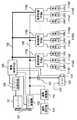
図1は、本実施形態における車両の電気系を示すブロック図である。エンジン101は、ベルト107によりオルタネータ等のエンジン発電機102に連結されている。エンジン発電機102は、電源線(電源バス)108を通じて、蓄電手段としてのバッテリ103および負荷制御手段110a〜110eに接続されている。 FIG. 1 is a block diagram showing an electric system of a vehicle in the present embodiment. The
負荷制御手段110aは負荷111a1〜111a3の給電制御を、負荷制御手段110bは負荷111b1〜111b3の給電制御を、負荷制御手段110eは負荷111e1〜111e3の給電制御を行う。これら負荷制御手段110a〜110eは、上記制御を行うのに必要な操作スイッチ(図示せず)やこの制御のための各種センサ(図示せず)を含んでおり、外部入力信号やこれらセンサの出力に応じて自己に属する負荷の出力制御又は断続を行う。 The
エンジン制御手段104は、エンジン101の制御を行うための制御装置であって、電源制御手段105と接続されており、エンジン101の種々の状態を検出するセンサ(図示せず)によって検出されたエンジン回転数等種々の情報を電源制御手段105に送信するとともに、電源制御手段105からの指令にしたがってエンジン101の出力を増減する。 The engine control means 104 is a control device for controlling the
廃熱回生器113は、エンジン101やエンジン101から排出される排気ガスの廃熱を動力に変換する装置である。廃熱発電機112は、廃熱回生器113によって変換された動力により発電し、その電力は電源バス108に出力される。 The
電源制御手段105は、エンジン発電機102、廃熱発電機112、バッテリ103、電源バス108などの状態を監視する。また、エンジン発電機102を制御するコントローラとしてのエンジン発電制御部、廃熱発電機112を制御するコントローラとしての廃熱発電制御部(何れも図示せず)を備えている。エンジン発電機102、及び廃熱発電機112の発電電力は、電源制御手段105からの指令により制御される。 The power control means 105 monitors the state of the
電源制御手段105は、多重信号伝送線路106を通じて負荷制御手段110a〜110bに接続されており、これら負荷制御手段110a〜110bと多重通信により双方向に情報を授受する。 The power control means 105 is connected to the load control means 110a to 110b through the multiplex
電源制御手段105にはバッテリ電流センサ107、温度センサ114、バッテリ電圧センサ(図示せず)が接続されており、バッテリ103の入出力電流、バッテリ温度、バッテリ電圧を受け取ってバッテリ103の状態(残容量)を監視する。 A
このように構成される本実施形態の車両の電気系では、電源バス108のバス電圧の安定化とともに、エンジン101の燃費改善を効果的に図るものである。以下、電源制御手段105によって実行される電力管理処理の動作について、図2に示すフローチャートの流れに従って説明する。なお、本実施形態において、電力供給元となるのは、エンジン発電機102(電力供給元α)、廃熱発電機112(電力供給元β)、及びバッテリ103(電力供給元γ)である。また、以下の電力管理処理は、所定時間(時間ステップ)毎に繰り返し実行される。 In the electric system of the vehicle of this embodiment configured as described above, the bus voltage of the
図2に示すステップ(以下、Sと記す)201では、各電力供給元の定常的に供給可能な最大供給電力、過渡最大供給電力及び過渡最小供給電力を算出する。過渡最大供給電力とは、各電力供給元の応答時間を考慮して次の時間ステップ(所定時間後)までに供給可能な最大供給電力を示す。また、同様に、過渡最小供給電力は、次の時間ステップまでに供給可能な最小供給電力を示す。 In step (hereinafter referred to as S) 201 shown in FIG. 2, the maximum supply power, the transient maximum supply power, and the transient minimum supply power that can be steadily supplied from each power supply source are calculated. The transient maximum supply power indicates the maximum supply power that can be supplied by the next time step (after a predetermined time) in consideration of the response time of each power supply source. Similarly, the transient minimum supply power indicates the minimum supply power that can be supplied by the next time step.
電力供給元α、βの最大供給電力は、エンジン発電機102や廃熱発電機112の最大供給電力、効率、パワー源となるエンジン101、廃熱回生器113から吸収可能な動力等によって決定される。この電力供給元α、βについての最大供給電力、過渡最大供給電力、及び過渡最小供給電力の算出方法については、後ほど詳しく説明する。電力供給元γの最大供給電力は、電源バス108のバス電圧を所定電圧以上に保持できる最大の放電電力として決定される。 The maximum supply power of the power supply sources α and β is determined by the maximum supply power of the
S202では、各電力供給元の供給電力に対する電力コストを算出する。電力コストは、供給電力がゼロ(0)[kW]から各電力供給元の最大供給電力までの間で所定電力間隔毎に算出され、単位電力量当たりのエンジン101の燃料消費増加量[g/kWh]で与えられる。 In S202, the power cost for the power supplied by each power supply source is calculated. The power cost is calculated at predetermined power intervals between the supply power of zero (0) [kW] and the maximum supply power of each power supply source, and the fuel consumption increase amount [g / kWh].
例えば、電力供給元α(エンジン発電)の電力コストについては、現在のエンジン回転数における、エンジン発電機102によって発電された供給電力がb_base[kW]であるときのエンジン101の燃料消費率をa1[g/kWh]とし、エンジン発電機102によって発電された供給電力がb[kW]であるときの燃料消費率をa2[g/kWh]とした場合、供給電力b[kW]に対応する電力コストは次式で求められる。但し、(b=0)の時の電力コストはゼロ(0)である。 For example, for the power cost of the power supply source α (engine power generation), the fuel consumption rate of the
(数1)
電力供給元αの電力コスト[g/kWh]=(a2×(b_base+b)−a1×b_base)/b
電力供給元β(廃熱発電)については、エンジン101の廃熱を動力源としているため、エンジン101の燃料消費量の増加が生じないため、電力コストは常にゼロ(0)とする。また、電力供給元γ(バッテリ)については、バッテリ充電時における充電電力の電力コストの時間平均値を算出し、これを電力コストとする。なお、電力供給元γ(バッテリ)の電力コストは、供給電力によって変化しないものとする。(Equation 1)
Electric power cost [g / kWh] = (a2 × (b_base + b) −a1 × b_base) / b
Since the power supply source β (waste heat power generation) uses the waste heat of the
S203では、負荷のスイッチやその他動作状況により算出される電気負荷の総必要電力である電気負荷必要電力を算出する。S204では、バッテリ103の充電要求電力を算出する。この充電要求電力は、バッテリ電圧、入出力電流、温度等に決定されるバッテリ103の残容量等によって決定され、バッテリ103が所定の上限電圧を超えない最大入力電力以下とする。 In S203, an electric load required power which is a total required electric power of the electric load calculated based on a load switch and other operating conditions is calculated. In S204, the required charging power of the
この充電要求電力については、バッテリ103以外の電力供給元α、βの最大供給電力を合計した合計電力が電気負荷必要電力より小さい場合、バッテリ103は放電を余儀なくされるため、充電要求電力はゼロに設定される。この充電要求電力の算出方法については、後ほど詳しく説明する。 With respect to the required charging power, if the total power obtained by summing the maximum supplied powers of the power supply sources α and β other than the
S205では、電気負荷要求電力が電力供給元α、β、γの最大供給電力の合計電力よりも大きいか否かを判定する。ここで、肯定判定される場合(電力不足)にはS213へ処理を移行し、否定判定される場合にはS208へ処理を進める。 In S205, it is determined whether the required electric load power is larger than the total power of the maximum supply power of the power supply sources α, β, γ. If an affirmative determination is made (power shortage), the process proceeds to S213. If a negative determination is made, the process proceeds to S208.
S213では、電気負荷要求電力が上記合計電力以下となるように負荷制御手段110a〜110eへ指令することで電気負荷の消費電力を削減する、S214では、各電力供給元の最大供給電力を配分電力とする。 In S213, the power consumption of the electrical load is reduced by instructing the load control means 110a to 110e so that the required electrical load power becomes equal to or less than the total power. In S214, the maximum supply power of each power supply source is allocated power. And
S208では、バッテリ103の充電要求電力がゼロ(0)以上であるか否かを判定する。ここで、充電要求電力がゼロ(0)以上の場合には、バッテリ103は、充電と同時に放電が不可能であるため、電力供給元γ(バッテリ)の最大供給電力をゼロ(0)とする。 In S208, it is determined whether the required charging power of the
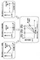
S210では、各電力供給元の配分電力を決定する。この配分電力の決定方法について、図3を用いて説明する。各電力供給元の配分電力は、各電力供給元からの供給電力の合計値が電気負荷要求電力と充電要求電力(同図は充電要求電力=0)の合計電力と等しく、さらに、各電力供給元の供給電力がその電力供給元の最大供給電力を超えないことを条件として、電力供給に伴う電力コストである燃料消費率が最小となる電力供給元の組み合わせを求めることで決定される。 In S210, the distribution power of each power supply source is determined. A method for determining the distributed power will be described with reference to FIG. The distribution power of each power supply source is such that the total value of the power supply from each power supply source is equal to the total power of the electric load request power and the charge request power (charge request power = 0 in the figure), and each power supply This is determined by obtaining a combination of power supply sources that minimizes the fuel consumption rate, which is the power cost associated with power supply, on condition that the original supply power does not exceed the maximum supply power of the power supply source.
同図に示すように、電力供給元α(エンジン発電)の電力コストは、供給電力に対する単位電力当たりの電力コストが変動するものであり、この変動を加味して各電力供給元の配分電力を決定している。そのため、電気系全体の電力コストが最小になるように各電力供給元の供給電力のバランスを調節することができる。その結果、燃費改善を効果的に図ることができる。 As shown in the figure, the power cost of the power supply source α (engine power generation) varies as the power cost per unit power with respect to the supplied power. Has been decided. Therefore, it is possible to adjust the balance of the supply power of each power supply source so that the power cost of the entire electric system is minimized. As a result, fuel efficiency can be effectively improved.
なお、本実施形態では、供給電力に対する単位電力あたりの電力コストが変動する電力供給元は、電力供給元α(エンジン発電)のみであるが、このような電力供給元が複数ある場合も、同様に配分電力を求める。 In the present embodiment, the power supply source whose power cost per unit power with respect to the supplied power varies is only the power supply source α (engine power generation), but the same applies when there are a plurality of such power supply sources. Find the power distribution.
S211では、各電力供給元の過渡応答を考慮し、各電力供給元の配分電力が過渡最小供給電力以上で過渡最大供給電力以下になるように補正を行う。図5(a)は、電力供給元αの配分電力が過渡最大供給電力よりも大きい場合を示している。このような場合、次の時間ステップまでに電力供給が追いつかず、結果として一時的な電力不足となり、電源バスのバス電圧が降下する可能性がある。 In S211, considering the transient response of each power supply source, correction is performed so that the distributed power of each power supply source is not less than the transient minimum supply power and not more than the transient maximum supply power. FIG. 5A shows a case where the distributed power of the power supply source α is larger than the transient maximum supply power. In such a case, the power supply cannot catch up by the next time step, resulting in a temporary power shortage and the bus voltage of the power supply bus may drop.
このような場合には、図5(b)に示すように、電力供給元αの配分電力を過渡最大供給電力に設定し直すとともに、過渡最大供給電力以上の供給しきれない電力を一時的に電力供給元β、γへ割り振り、必要な電力が賄えるように、各電力供給元の配分電力を補正する。但し、電力供給元β、γ共に、その配分電力が過渡最小供給電力以上で過渡最大供給電力以下となるよう制限を加える。なお、この制限内で補正しきれない場合は、負荷制御手段110a〜110eにより、負荷電力を減少させるようにすればよい。 In such a case, as shown in FIG. 5B, the distribution power of the power supply source α is reset to the transient maximum supply power, and the power that cannot be supplied more than the transient maximum supply power is temporarily set. Allocating to the power supply sources β and γ, the distribution power of each power supply source is corrected so that the necessary power can be covered. However, both the power supply sources β and γ are limited so that the distributed power is not less than the transient minimum supply power and not more than the transient maximum supply power. If correction cannot be made within this limit, the load power may be reduced by the load control means 110a to 110e.
一方、図6(a)は、電力供給元αの配分電力が過渡最小供給電力より小さい場合を示している。このような場合、次の時間ステップまでに電力を減少させることができないため、結果として一時的に電力過剰となり、電源バスのバス電圧が上昇する可能性がある。 On the other hand, FIG. 6A shows a case where the distribution power of the power supply source α is smaller than the transient minimum supply power. In such a case, the power cannot be reduced by the next time step. As a result, the power temporarily becomes excessive and the bus voltage of the power supply bus may increase.
このような場合には、図6(b)に示すように、電力供給元αの配分電力を過渡最小供給電力に設定し直すとともに、電力供給元βの配分電力を減らすように、配分電力を補正する。但し、給電元β、γ共に、その配分電力が過渡最小供給電力以上で過渡最大供給電力以下となるよう制限を加える。 In such a case, as shown in FIG. 6B, the distributed power of the power supply source α is reset to the transient minimum supply power, and the distributed power is reduced so as to reduce the distributed power of the power supply source β. to correct. However, both the power supply sources β and γ are limited so that the distributed power is not less than the transient minimum supply power and not more than the transient maximum supply power.
なお、この制限内で補正しきれない場合には、先ず、未補正の過剰電力をバッテリ103に充電した場合に電源バスのバス電圧が規定値以上になるか否かを判定し、規定値以上にならない場合はバッテリ103に充電する。一方、規定値以上になる場合は、負荷制御手段110a〜110eにより、負荷電力を増加させるようにすればよい。 If correction cannot be made within this limit, first, it is determined whether or not the bus voltage of the power supply bus exceeds the specified value when the
この図5、図6に示した具体例以外において、各電力供給元の配分電力が過渡最小供給電力以上で過渡最大供給電力以下とならない場合は、同様の方法で相互に補正をかけるようにする。これにより、電力供給元の応答遅れによる電気系のバス電圧の一時的な電圧変動を抑制することができる。 Other than the specific examples shown in FIGS. 5 and 6, when the distribution power of each power supply source is not less than the transient minimum supply power and not the transient maximum supply power, correction is performed in the same manner. . Thereby, the temporary voltage fluctuation of the electric bus voltage due to the response delay of the power supply source can be suppressed.
S212では、各電力供給元の配分電力を示す給電指令量を各電力供給元へ送信する。そして、次の時間ステップにおいて、S201へ処理を移行し、上述した処理を繰り返し行う。 In S212, a power supply command amount indicating the distributed power of each power supply source is transmitted to each power supply source. In the next time step, the process proceeds to S201, and the above-described process is repeated.
(充電要求電力の算出方法)
図4を用いて、S204における充電要求電力の算出方法について説明する。バッテリ103の充放電は、電力コストが低い場合にバッテリ103に電力を蓄え、電力コストが高い場合に電力を放出することにより燃費の向上につながる。(Calculation method of required charging power)
With reference to FIG. 4, a method for calculating the required charging power in S204 will be described. Charging / discharging of the
図4に示すように、充電要求電力を算出する際の入力値としては、バッテリ残容量に基づいて設定される目標コスト、電力供給源γを除く(バッテリ103は同時に充放電ができないため)電力供給源α、βの電力コスト、バッテリ103の最大充電電力(バッテリ103が所定の上限電圧を超えない最大入力電力)、及び電気負荷必要電力である。 As shown in FIG. 4, the input value for calculating the required charging power excludes the target cost set based on the remaining battery capacity and the power supply source γ (because the
これらの入力値を元に、目標コスト以下で出力できる電力供給源α、βの最大の供給電力から、電気負荷必要電力を減じた電力を充電要求電力とする。但し、充電要求電力は、ゼロ(0)以上で最大充電電力以下とする。これにより、充電要求電力は、バッテリ103の残容量に基づいて設定される目標コストによって管理することができる。 Based on these input values, power obtained by subtracting the required electric load power from the maximum supply power of the power supply sources α and β that can be output at a target cost or less is set as the required charging power. However, the required charging power is not less than zero (0) and not more than the maximum charging power. As a result, the required charging power can be managed by the target cost set based on the remaining capacity of the
目標コストとは、バッテリ103に充電する際の電力コストの目標を示すもので、目標コストマップに示すように、バッテリ残容量に基づき、バッテリ残量が多いほど小さく設定され、残量が少ないほど大きく設定される。 The target cost indicates the target of the power cost when charging the
例えば、バッテリ残量が十分で目標コストがゼロの場合は、廃熱回生のような電力コストがゼロ(0)の電力以外は、バッテリ103を充電しないようにする。また、バッテリ残量が少なくなると、駐車中にバッテリ103が電気負荷電力を賄う際に電力不足とならないように、目標コストを徐々に大きくして、電力コストを発生してでも充電を行うようにする。 For example, when the remaining amount of the battery is sufficient and the target cost is zero, the
従って、バッテリ残量が十分な場合には目標コストを低く、低い電力コストが実現できる場合は、充電要求電力がゼロより大きくなり、図2のS210において、目標コストを満たす電力コストの電力が充電される。また、低い発電コストが実現できない場合は、充電要求電力がゼロとなり、バッテリ103が電力供給元のひとつとして扱われ、バッテリ103に蓄えた電気エネルギーが供給できるようになる。 Accordingly, when the remaining battery capacity is sufficient, the target cost is low, and when a low power cost can be realized, the required charging power becomes greater than zero, and in S210 of FIG. 2, the power of the power cost that satisfies the target cost is charged. Is done. When low power generation cost cannot be realized, the required charging power becomes zero, the
一方、バッテリ残量が減っていくと目標コストが徐々に高くなるため、電力コストを発生しても充電を行うようになるが、目標コスト以下で実現できる最大限の電力で充電するようにするため、目標コストが比較的低い段階でバッテリ残量を回復することができる。これにより、バッテリ上がりのリスクを回避しつつ、好適な燃費効果を得ることができる。 On the other hand, as the remaining battery level decreases, the target cost will gradually increase, so charging will occur even if there is a power cost, but it will be charged with the maximum power that can be achieved below the target cost. Therefore, the remaining battery level can be recovered at a stage where the target cost is relatively low. Thereby, it is possible to obtain a suitable fuel efficiency effect while avoiding the risk of battery exhaustion.
(電力供給元α、βの最大供給電力、過渡最大/最小供給電力の算出方法)
電力供給元α、βの最大供給電力、過渡最大供給電力、及び過渡最小供給電力は、各電力供給元のパワー源(電力供給元αの場合はエンジントルク、電力供給元βの場合は熱量)から電力に変換するために利用可能なパワーに関する情報に基づいて算出する。(Calculation method of maximum supply power and transient maximum / minimum supply power of power supply sources α and β)
The maximum supply power, transient maximum supply power, and transient minimum supply power of the power supply sources α and β are the power sources of the respective power supply sources (engine torque in the case of the power supply α and heat quantity in the case of the power supply β) To calculate power based on information about power available for conversion from power to power.
すなわち、図8に示すように、エンジン発電機102や廃熱発電機112等の電力変換器は、その電力の元となるパワー源から利用可能なパワーに関する情報(エンジントルクや熱量)をエンジン制御手段や廃熱回生器から取得する。このパワーに関する情報に基づいて、最大供給電力、過渡最大供給電力、及び過渡最小供給電力を算出して配分決定部へ送る。配分決定部では、図2に示した電力管理処理におけるS202〜S212を実行して、各電力変換器への配分電力を決定し、この配分電力を示す給電指令量を各電力変換器へ送信する。 That is, as shown in FIG. 8, the power converters such as the
このように、パワー源から電力変換(発電)の為に利用可能なパワーに関する情報に基づいて最大供給電力、過渡最大供給電力、及び過渡最小供給電力を算出するため、例えば、車両の急加速中にエンジン発電の為にエンジントルクを利用したくない場合には、電力変換の為に利用可能なパワーを絞って、エンジンのトルク消費を抑えることができる。 Thus, in order to calculate the maximum supply power, the transient maximum supply power, and the transient minimum supply power based on information about power available for power conversion (power generation) from the power source, for example, during rapid acceleration of the vehicle In the case where it is not desired to use the engine torque for engine power generation, it is possible to reduce the engine torque consumption by reducing the power available for power conversion.
すなわち、上述した、従来の車両用電気系の管理方法では、エンジン発電による供給可能電力は、エンジンの現在回転数における最大供給可能量を設定するため、電力の要求があれば、その最大供給可能量の電力を発電する。このため、例えば、エンジン発電によるエンジンのトルク消費を抑えたいという場合、その要望に対応できない問題があったが、本実施形態のように、パワー源から電力変換(発電)の為に利用可能なパワーに関する情報に基づいて最大供給電力、過渡最大供給電力、及び過渡最小供給電力を算出することで、上記問題が解消される。 In other words, in the above-described conventional vehicle electric system management method, the maximum power that can be supplied by engine power generation is set at the current rotational speed of the engine. Generate the amount of power. For this reason, for example, when it is desired to suppress engine torque consumption due to engine power generation, there has been a problem that the request cannot be met. However, as in this embodiment, it can be used for power conversion (power generation) from a power source. The above problem is solved by calculating the maximum supply power, the transient maximum supply power, and the transient minimum supply power based on the information regarding power.
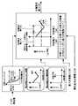
図9に、エンジン発電機の制御部の内部構成を示す。なお、廃熱発電機の制御部については、このエンジン発電機の制御部の内部構成と基本的な構成は同様であるため、その説明を省略する。 FIG. 9 shows the internal configuration of the control unit of the engine generator. In addition, about the control part of a waste-heat generator, since the internal structure and basic structure of the control part of this engine generator are the same, the description is abbreviate | omitted.
先ず、電力変換(発電)の為に利用可能なエンジントルクの情報を入力すると、105aにおいて、エンジントルクにエンジン発電機102の回転数(N)を乗じて、利用可能なパワー情報を演算する。 First, when information on the engine torque that can be used for power conversion (power generation) is input, the available power information is calculated by multiplying the engine torque by the rotational speed (N) of the
105bでは、エンジン発電機102の電力変換最大量(回転数に依存する場合は、これも考慮して)で制限することで、電力変換(発電)可能なパワー量が決まる。そして、105cにおいて、このパワー量にエンジン発電機102の効率(η)を乗じて、発電(供給)可能な供給可能電力(xn_av)を算出する。このように、電力変換器であるエンジン発電機102や廃熱発電機112の効率や電力変換最大量等の性能を加味することで、正確な供給可能電力を算出することができる。 In 105b, the amount of power that can be converted into electric power (power generation) is determined by limiting with the maximum power conversion amount of the engine generator 102 (considering this if it depends on the rotational speed). Then, at 105c, this power amount is multiplied by the efficiency (η) of the
なお、上述したように、図9では、利用可能トルクを入力しているが、この利用可能トルクの上・下限値(最大・最小値)を入力することで、供給電力(xn_av)の上・下限値である最大(定常)供給電力と最小(定常)供給電力を得ることができる。 Note that, as described above, the available torque is input in FIG. 9. However, by inputting the upper and lower limit values (maximum / minimum values) of this available torque, the upper and lower limits of the supplied power (xn_av) are input. The maximum (steady) supply power and the minimum (steady) supply power that are the lower limit values can be obtained.
この供給可能電力(xn_av)は、電力変換器(エンジン発電の場合はエンジン発電機)と電力変換器を制御する制御装置(エンジン発電の場合はエンジン発電機の制御部)とからなるシステムの離散化モデルG(z)へ入力し、次の時間ステップ(所定時間後)に発電(供給)可能な過渡発電(供給)電力(yn_av)を算出する。なお、最大(定常)供給電力や最小(定常)供給電力を離散化モデルG(z)へ入力した場合には、過渡最大供給電力電力や過渡最小供給電力が算出される。 This suppliable power (xn_av) is a discrete value of a system including a power converter (engine generator in the case of engine power generation) and a control device (control unit of the engine generator in the case of engine power generation) that controls the power converter. Is input to the conversion model G (z), and transient power generation (supply) power (yn_av) that can be generated (supplied) at the next time step (after a predetermined time) is calculated. When the maximum (steady) supply power or the minimum (steady) supply power is input to the discretization model G (z), the transient maximum supply power or the transient minimum supply power is calculated.
このように、離散化モデルG(z)に供給可能電力(xn_av)を入力することで、電力変換器やその電力変換器を制御する制御装置の遅れ(応答遅れ等)を考慮して供給電力を算出することができる。 In this way, by supplying the suppliable power (xn_av) to the discretized model G (z), the supplied power is considered in consideration of the delay (response delay, etc.) of the power converter and the control device that controls the power converter. Can be calculated.
ここで、離散化モデルG(z)について、図10を用いて説明する。図10(a)は、エンジン発電機や廃熱発電機等の制御部であるコントローラC(s)と、プラントP(s)としての電力変換器(エンジン発電機や廃熱発電機)からなる制御系の連続モデルである。この制御系においては、発電(供給)指令X(s)に対し、実際の発電(供給)量Y(s)が追従するように、コントローラC(s)がプラントP(s)を制御する。この制御系を1つの伝達関数で表現し、さらに、離散化したものが、図10(b)に示す離散化モデルG(z)である。 Here, the discretization model G (z) will be described with reference to FIG. FIG. 10A shows a control system comprising a controller C (s) which is a control unit such as an engine generator or a waste heat generator, and a power converter (engine generator or waste heat generator) as a plant P (s). It is a continuous model. In this control system, the controller C (s) controls the plant P (s) so that the actual power generation (supply) amount Y (s) follows the power generation (supply) command X (s). A discretized model G (z) shown in FIG. 10B represents this control system expressed by one transfer function and further discretized.
これにより、配分決定部では、供給可能電力(xn_av)を参照しながら、過度供給電力(yn_av)を考慮して、次の時間ステップ(所定時間後)に供給可能な給電指令量(yn_com)を決定することができる。従って、次の時間ステップで実際に供給可能な電力の範囲内で、最終的な目標となる給電量となるように、給電指令量(yn_com)を逐次更新することが可能になる。 As a result, the distribution determining unit determines the power supply command amount (yn_com) that can be supplied in the next time step (after a predetermined time) in consideration of the excessive supply power (yn_av) while referring to the supplyable power (xn_av). Can be determined. Therefore, the power supply command amount (yn_com) can be sequentially updated so that the final target power supply amount is within the range of power that can be actually supplied in the next time step.
給電指令量(yn_com)は、離散化モデルG(z)105dの逆モデル1/G(s)に入力され、次の時間ステップで電力変換器へ入力すべき給電指令入力値(xn_com)を算出する。これにより、電力変換器への最終指令値を算出することができる。この指令値(xn_com)は、離散化モデルG(z)に入力される。 The power supply command amount (yn_com) is input to the
なお、配分決定部において決定される給電指令量(yn_com)は、例えば、図11(a)、(b)に示すように、時間(t0)の時点で、次の時間ステップ(t1)で供給可能電力(xn_av)のとりうる上下限値(xn_av_up)、(xn_av_low)をそれぞれ入力することで、次の時間ステップで発電(供給)可能な電力量の上下限値(yn_av_up)、(xn_av_low)が算出できるため、この範囲内で給電指令量(yn_com)が決定されるものである。The power supply command amount (yn_com) determined by the distribution determination unit is, for example, as shown in FIGS. 11A and 11B, at the time (t0 ), the next time step (t1 ). By inputting the upper and lower limit values (xn_av_up) and (xn_av_low) that can be supplied in (n), the upper and lower limit values (yn_av_up) and (xn_av_low) of the amount of power that can be generated (supplied) in the next time step ) Can be calculated, the power supply command amount (yn_com) is determined within this range.
すなわち、図10(c)で示すように、(yn)は過去の(yn)、(xn)と、次の時間ステップで入力される(xn)で決定するため、この(xn)に(xn_av_up)をいれると(yn_av_up)が求まり、(xn_av_low)を入れると(yn_av_low)が求まる。逆に、(xn)は過去の(yn)、(xn)と次の時間ステップで欲しい値(yn)で決まるため、この(yn)に(yn_com)を入れることで、次の時間ステップで電力変換器の制御部へ指令すべき値(xn_com)を演算することが出来る。 That is, as shown in FIG. 10C, (yn) is determined by the past (yn), (xn) and (xn) input at the next time step, and therefore (xn) is changed to (xn_av_up). ), (Yn_av_up) is obtained, and when (xn_av_low) is inserted, (yn_av_low) is obtained. Conversely, (xn) is determined by the past (yn), (xn) and the desired value (yn) at the next time step, so by adding (yn_com) to this (yn), the power at the next time step A value (xn_com) to be commanded to the control unit of the converter can be calculated.
このように、電力変換器の時定数による発電(供給)遅れを含んで、発電可能な量を推定することにより、実際の発電指令がきても追従可能になり、電源バスのバス電圧降下も防止出来る。 In this way, by estimating the amount of power that can be generated, including the delay in power generation (supply) due to the time constant of the power converter, it is possible to follow even if an actual power generation command is received, preventing the bus voltage drop of the power bus I can do it.
(変形例1)
本実施形態では、図4に示したように、バッテリ残容量に基づいて目標コストを設定するものであるが、図7に示すように、電気負荷必要電力が大きいほど、目標コストが高くなるように設定するようにしてもよい。これにより、電気負荷必要電力が大きいときに目標コストを高めに設定することで、バッテリ電力の減少を抑え、バッテリ上がりを防ぐことができる。(Modification 1)
In the present embodiment, as shown in FIG. 4, the target cost is set based on the remaining battery capacity. However, as shown in FIG. 7, the larger the required electric load power, the higher the target cost. You may make it set to. Thus, by setting the target cost higher when the electric load power requirement is large, it is possible to suppress a decrease in battery power and to prevent the battery from running out.
(変形例2)
図9に示した制御系において、図12(a)に示すように、エンジンの出力トルクの応答遅れ要素PE(s)を組み込むことも可能である。これにより、実際には遅れて出力可能となるトルク情報を利用することができ、この値に基づいて制御するため、発電(供給)時にエンジントルク不足を解消でき、ドラビリが確保出来るようになる。(Modification 2)
In the control system shown in FIG. 9, a response delay element PE (s) of the engine output torque can be incorporated as shown in FIG. As a result, torque information that can be output in a delayed manner can be used, and control is performed based on this value, so that engine torque deficiency can be resolved during power generation (supply), and drivability can be secured.
また、図12(b)に示すように、プラントP(s)の後に応答遅れ要素PE(s)’を挿入することで、簡易的に対応することも可能である。この場合、図9で示した離散化モデルG(z)は、P(s)とPE(s)’を一つの要素として取り扱う事ができる。 Further, as shown in FIG. 12B, it is possible to easily cope with this by inserting a response delay element PE (s) 'after the plant P (s). In this case, the discretized model G (z) shown in FIG. 9 can handle P (s) and PE (s) ′ as one element.
101・・・エンジン、102・・・エンジン発電機、103・・・バッテリ、104・・・エンジン制御手段、105・・・電源制御手段、106・・・多重通信線、107・・・電流センサ、108・・・電源線(電源バス)、110a〜e・・・負荷制御手段、112・・・廃熱発電機、113・・・廃熱回生器、114・・・温度センサ DESCRIPTION OF
Claims (18)
Translated fromJapanese前記各電力供給元の供給電力に対する、単位電力当りのコストである電力コストの変動を加味して、前記電気系全体の電力コストが最小となるように前記各電力供給元への配分電力を決定する配分決定手段と、
前記複数の電力供給元から全体として前記電気系へ供給する必要がある電力を示す需要電力を取得する需要電力取得手段と、
前記各電力供給元から供給可能な電力を示す最大供給電力、及び前記各電力供給元の供給電力に対する、単位電力当りのコストである電力コストの情報を算出する電力情報算出手段と、を備え、
前記複数の電力供給元のうち、少なくとも1つの電力供給元は、パワー源からのパワーを電力に変換する電力変換器を有し、
前記電力情報算出手段は、前記電力変換器を有する前記電力供給元の最大供給電力について、その電力供給元のパワー源から電力変換の為に利用可能なパワーに関する情報に基づいて算出し、
前記配分決定手段は、前記各電力供給元の供給電力を合計した合計電力が前記需要電力と等しく、さらに、前記各電力供給元の供給電力がその電力供給元の最大供給電力を超えないことを条件として、前記電気系全体の電力コストが最小となる前記各電力供給元への配分電力を決定することを特徴とする電気系の電源制御装置。An electric power supply control device that supplies power supplied from a plurality of power supply sources to an electric load,
The distribution power to each power supply source is determined so that the power cost of the entire electrical system is minimized by taking into account the fluctuation of the power cost, which is the cost per unit power, with respect to the supply power of each power supply source Distribution determination meansto
Demand power acquisition means for acquiring demand power indicating power that needs to be supplied to the electrical system as a whole from the plurality of power supply sources;
Power information calculation means for calculating information on the maximum supply power indicating the power that can be supplied from each power supply source, and the power cost that is the cost per unit power for the supply power of each power supply source,
Among the plurality of power supply sources, at least one power supply source has a power converter that converts power from a power source into power,
The power information calculation means calculates the maximum supply power of the power supply source having the power converter based on information about power available for power conversion from the power source of the power supply source,
The distribution determining means determines that the total power obtained by summing the supply power of each power supply source is equal to the demand power, and that the supply power of each power supply source does not exceed the maximum supply power of the power supply source. An electric power control apparatus for an electric system, characterizedin that,as a condition, the electric power distributed to each electric power supply source that minimizes the electric power cost of the entire electric system is determined .
前記電気負荷の必要電力である電気負荷必要電力を取得する必要電力取得手段と、
前記蓄電手段の充電要求電力を取得する充電要求電力取得手段と、を備え、
前記需要電力取得手段は、前記電気負荷必要電力と前記充電要求電力との和を需要電力として取得することを特徴とする請求項1記載の電気系の電源制御装置。The electrical system includes power storage means,
A required power acquisition means for acquiring a required power of the electrical load that is a required power of the electrical load;
Charging required power acquisition means for acquiring charging required power of the power storage means,
The demand power acquiring means, the electric load required power and the charge required power and electrical system power supply control apparatus according to claim1, wherein the obtaining the sum as demand power.
前記蓄電手段の残容量に基づいて前記蓄電手段を充電する際の目標コストを設定する目標コスト設定手段を備え、
前記目標コスト、前記蓄電手段を除く前記各電力供給元の電力コスト、前記蓄電手段の最大充電電力、及び前記電気負荷必要電力に基づいて、前記目標コスト以下で出力できる前記各電力供給元の最大の電力から前記電気負荷必要電力を減じた電力を充電要求電力とすることを特徴とする請求項2記載の電気系の電源制御装置。The charging request power acquisition means is
Comprising target cost setting means for setting a target cost for charging the power storage means based on the remaining capacity of the power storage means;
Based on the target cost, the power cost of each power supply source excluding the power storage means, the maximum charging power of the power storage means, and the electric load required power, the maximum of each power supply source that can be output below the target cost The electric power control apparatus according to claim2, wherein electric power obtained by subtracting the electric load required electric power from the electric power is set as charge request electric power.
前記蓄電手段の残容量が少ないほど前記目標コストを大きく設定し、
前記蓄電手段の残容量が多いほど前記目標コストを小さく設定することを特徴とする請求項3記載の電気系の電源制御装置。The target cost setting means includes
The smaller the remaining capacity of the power storage means, the larger the target cost,
4. The electric system power supply control device according to claim3, wherein the target cost is set smaller as the remaining capacity of the power storage means increases.
前記配分決定手段は、前記最大供給電力、及び前記過渡供給電力に基づいて前記電力供給元への配分電力を決定することを特徴とする請求項1〜6の何れか1項に記載の電気系の電源制御装置。The power information calculation means calculates the maximum supply power that can be constantly supplied from each power supply source, calculates the transient supply power that can be supplied after a predetermined time from the power supply source,
The electrical system according to anyone of claims1 to6 , wherein the distribution determination unit determines the distribution power to the power supply source based on the maximum supply power and the transient supply power. Power supply control device.
前記配分決定手段は、前記電力供給元の配分電力がその電力供給元における過渡最小供給電力以上で過渡最大供給電力以下となるように補正する補正手段を備えることを特徴とする請求項7記載の電気系の電源制御装置。The power information calculation means calculates an upper limit value of the transient supply power, a transient maximum supply power indicating a lower limit value, and a transient minimum supply power,
It said allocation determining means, according to claim7, characterized in that it comprises a correction means for the power supply source of the allocation power is corrected so as not to exceed the transient maximum supply power in the transient minimum supply power or at the power supply source Electric power control device.
前記パワー源から電力変換の為に利用可能なパワーに関する情報に基づいて、前記電力供給元から供給可能な電力を示す最大供給電力の情報を算出する電力情報算出手段と、
前記最大供給電力から決定された給電指令量に基づいて、前記電力供給元への最終指令値を決定する最終指令値決定手段と、を備えることを特徴とする電気系の電源制御装置。A power supply control device for an electric system comprising a power supply source having a power converter for converting power from a power source into power, and supplying power supplied from the power supply source to an electric load,
Power information calculation means for calculating information on maximum supply power indicating power that can be supplied from the power supply source based on information on power available for power conversion from the power source;
An electric power control apparatus comprising: final command value determining means for determining a final command value to the power supply source based on a power supply command amount determined from the maximum supply power.
前記最大供給電力、及び前記過渡供給電力に基づいて前記給電指令量を決定する給電指令量決定手段を備えることを特徴とする請求項12又は13記載の電気系の電源制御装置。The power information calculation means calculates the maximum supply power that can be constantly supplied from the power supply source, calculates the transient supply power that can be supplied after a predetermined time from the power supply source,
The maximum supply power, and electrical system power supply control apparatus according to claim12 or13, wherein further comprising a power supply command amount determining means for determining the power supply command amount based on the transient power supply.
前記給電指令量決定手段は、前記給電指令量が前記過渡最小供給電力以上で前記過渡最大供給電力以下となるように補正する補正手段を備えることを特徴とする請求項14記載の電気系の電源制御装置。The power information calculating means calculates an upper limit value of the transient supply power, a transient maximum supply power indicated as a lower limit value, and a transient minimum supply power,
15. The electric power source according to claim14 , wherein the power supply command amount determining means includes correction means for correcting the power supply command amount so that the power supply command amount is greater than or equal to the transient minimum supply power and less than or equal to the transient maximum supply power. Control device.
Priority Applications (4)
| Application Number | Priority Date | Filing Date | Title |
|---|---|---|---|
| JP2004356030AJP4622496B2 (en) | 2004-12-08 | 2004-12-08 | Electric power control device |
| US11/253,669US7463949B2 (en) | 2004-12-08 | 2005-10-20 | Power control apparatus and method for electrical system of vehicle |
| DE102005058676ADE102005058676A1 (en) | 2004-12-08 | 2005-12-08 | Device and method for power control for an electrical system of a vehicle |
| CN2005101294501ACN1794532B (en) | 2004-12-08 | 2005-12-08 | Power control apparatus for electrical system of vehicle |
Applications Claiming Priority (1)
| Application Number | Priority Date | Filing Date | Title |
|---|---|---|---|
| JP2004356030AJP4622496B2 (en) | 2004-12-08 | 2004-12-08 | Electric power control device |
Publications (2)
| Publication Number | Publication Date |
|---|---|
| JP2006166639A JP2006166639A (en) | 2006-06-22 |
| JP4622496B2true JP4622496B2 (en) | 2011-02-02 |
Family
ID=36500382
Family Applications (1)
| Application Number | Title | Priority Date | Filing Date |
|---|---|---|---|
| JP2004356030AExpired - Fee RelatedJP4622496B2 (en) | 2004-12-08 | 2004-12-08 | Electric power control device |
Country Status (4)
| Country | Link |
|---|---|
| US (1) | US7463949B2 (en) |
| JP (1) | JP4622496B2 (en) |
| CN (1) | CN1794532B (en) |
| DE (1) | DE102005058676A1 (en) |
Families Citing this family (53)
| Publication number | Priority date | Publication date | Assignee | Title |
|---|---|---|---|---|
| US10569792B2 (en) | 2006-03-20 | 2020-02-25 | General Electric Company | Vehicle control system and method |
| US9733625B2 (en) | 2006-03-20 | 2017-08-15 | General Electric Company | Trip optimization system and method for a train |
| US10308265B2 (en) | 2006-03-20 | 2019-06-04 | Ge Global Sourcing Llc | Vehicle control system and method |
| US9233696B2 (en) | 2006-03-20 | 2016-01-12 | General Electric Company | Trip optimizer method, system and computer software code for operating a railroad train to minimize wheel and track wear |
| US8924049B2 (en) | 2003-01-06 | 2014-12-30 | General Electric Company | System and method for controlling movement of vehicles |
| JP4479488B2 (en)* | 2004-12-01 | 2010-06-09 | 株式会社デンソー | Exhaust power generator |
| JP4715486B2 (en)* | 2005-12-06 | 2011-07-06 | 株式会社デンソー | Power control device |
| US9527518B2 (en) | 2006-03-20 | 2016-12-27 | General Electric Company | System, method and computer software code for controlling a powered system and operational information used in a mission by the powered system |
| US8249763B2 (en)* | 2006-03-20 | 2012-08-21 | General Electric Company | Method and computer software code for uncoupling power control of a distributed powered system from coupled power settings |
| US8370007B2 (en) | 2006-03-20 | 2013-02-05 | General Electric Company | Method and computer software code for determining when to permit a speed control system to control a powered system |
| US8126601B2 (en) | 2006-03-20 | 2012-02-28 | General Electric Company | System and method for predicting a vehicle route using a route network database |
| US8788135B2 (en) | 2006-03-20 | 2014-07-22 | General Electric Company | System, method, and computer software code for providing real time optimization of a mission plan for a powered system |
| US8401720B2 (en) | 2006-03-20 | 2013-03-19 | General Electric Company | System, method, and computer software code for detecting a physical defect along a mission route |
| US9156477B2 (en) | 2006-03-20 | 2015-10-13 | General Electric Company | Control system and method for remotely isolating powered units in a vehicle system |
| US8473127B2 (en) | 2006-03-20 | 2013-06-25 | General Electric Company | System, method and computer software code for optimizing train operations considering rail car parameters |
| US9266542B2 (en)* | 2006-03-20 | 2016-02-23 | General Electric Company | System and method for optimized fuel efficiency and emission output of a diesel powered system |
| US9201409B2 (en) | 2006-03-20 | 2015-12-01 | General Electric Company | Fuel management system and method |
| US8290645B2 (en) | 2006-03-20 | 2012-10-16 | General Electric Company | Method and computer software code for determining a mission plan for a powered system when a desired mission parameter appears unobtainable |
| US9689681B2 (en) | 2014-08-12 | 2017-06-27 | General Electric Company | System and method for vehicle operation |
| US8370006B2 (en) | 2006-03-20 | 2013-02-05 | General Electric Company | Method and apparatus for optimizing a train trip using signal information |
| US8346416B2 (en) | 2006-06-26 | 2013-01-01 | Azure Dynamics, Inc. | Method, apparatus, signals and media, for selecting operating conditions of a genset |
| US7826939B2 (en) | 2006-09-01 | 2010-11-02 | Azure Dynamics, Inc. | Method, apparatus, signals, and medium for managing power in a hybrid vehicle |
| US8392882B2 (en) | 2006-11-30 | 2013-03-05 | Caterpillar Inc. | Engine state-based control of software functions |
| JP4306746B2 (en)* | 2007-03-09 | 2009-08-05 | 株式会社デンソー | Vehicle power supply |
| DE102007013345B4 (en)* | 2007-03-20 | 2022-07-07 | Airbus Operations Gmbh | Energy control device for an aircraft |
| JP4695112B2 (en)* | 2007-03-26 | 2011-06-08 | 株式会社小糸製作所 | Vehicle headlamp lamp unit |
| JP4743161B2 (en) | 2007-05-17 | 2011-08-10 | 株式会社デンソー | Vehicle power supply control device |
| DE102008043251A1 (en)* | 2008-10-29 | 2010-05-06 | Robert Bosch Gmbh | Redundant parallel operation of vehicle electrical system generators |
| CN101771274B (en)* | 2008-12-31 | 2013-06-12 | 深圳市科陆电子科技股份有限公司 | Method for improving operating efficiency of thermal generator set |
| US9834237B2 (en) | 2012-11-21 | 2017-12-05 | General Electric Company | Route examining system and method |
| US8234023B2 (en)* | 2009-06-12 | 2012-07-31 | General Electric Company | System and method for regulating speed, power or position of a powered vehicle |
| JP5210989B2 (en)* | 2009-07-17 | 2013-06-12 | 株式会社 商船三井 | Car carrier |
| JP5126751B2 (en)* | 2009-09-18 | 2013-01-23 | 西芝電機株式会社 | Marine electric propulsion system |
| JP5110112B2 (en)* | 2010-03-26 | 2012-12-26 | 株式会社デンソー | Vehicle power supply control device |
| US8823203B2 (en) | 2009-11-12 | 2014-09-02 | Denso Corporation | Controller for engine |
| KR101611287B1 (en)* | 2009-11-13 | 2016-04-11 | 엘지전자 주식회사 | Smart metering device |
| WO2011074330A1 (en)* | 2009-12-15 | 2011-06-23 | 日本碍子株式会社 | Control device for secondary battery, and control method for secondary battery |
| JP5163768B2 (en)* | 2010-07-27 | 2013-03-13 | 株式会社デンソー | VEHICLE POWER MANAGEMENT SYSTEM, VEHICLE POWER INFORMATION MANAGEMENT DEVICE, AND VEHICLE ELECTRIC LOAD |
| JP5541126B2 (en) | 2010-12-07 | 2014-07-09 | 株式会社デンソー | Charge control device for secondary battery |
| JP5370402B2 (en)* | 2011-03-28 | 2013-12-18 | 株式会社デンソー | Air conditioner for vehicles |
| JP5741365B2 (en)* | 2011-10-14 | 2015-07-01 | 富士通株式会社 | Regulator device |
| US9293914B2 (en)* | 2011-11-04 | 2016-03-22 | Kohler Co | Power management system that includes a generator controller |
| FR2983653B1 (en)* | 2011-12-06 | 2014-01-17 | Renault Sa | METHOD FOR MANAGING AN ALTERNATOR ASSOCIATED WITH AT LEAST ONE BATTERY OF POWER SUPPLY AND DRIVEN BY A THERMAL MOTOR |
| DE102012206772B4 (en)* | 2012-04-25 | 2024-08-22 | Bayerische Motoren Werke Aktiengesellschaft | Support storage with center tap |
| EP2669172A1 (en)* | 2012-06-01 | 2013-12-04 | ABB Technology AG | Method and system for predicting the performance of a ship |
| US9669851B2 (en) | 2012-11-21 | 2017-06-06 | General Electric Company | Route examination system and method |
| US9682716B2 (en) | 2012-11-21 | 2017-06-20 | General Electric Company | Route examining system and method |
| US9518497B2 (en) | 2013-07-24 | 2016-12-13 | Cummins, Inc. | System and method for determining the net output torque from a waste heat recovery system |
| CA2997565A1 (en)* | 2015-09-11 | 2017-03-16 | Invertedpower Pty Ltd | A controller for an inductive load having one or more inductive windings |
| US10287923B2 (en)* | 2015-12-18 | 2019-05-14 | Cummins, Inc. | Flow and pressure estimators in a waste heat recovery system |
| CN106184080B (en)* | 2016-06-30 | 2020-04-14 | 大连楼兰科技股份有限公司 | On-board power grid management system and method of using the same |
| CN109066942B (en)* | 2018-09-12 | 2023-09-22 | 蔚来(安徽)控股有限公司 | Energy management method and device and mobile charging vehicle |
| CN111137230A (en)* | 2018-11-06 | 2020-05-12 | 宝沃汽车(中国)有限公司 | Power supply system and vehicle |
Family Cites Families (11)
| Publication number | Priority date | Publication date | Assignee | Title |
|---|---|---|---|---|
| JPH07231569A (en)* | 1994-02-21 | 1995-08-29 | Mitsubishi Heavy Ind Ltd | Unit for determining distribution of generated power |
| US5820172A (en)* | 1997-02-27 | 1998-10-13 | Ford Global Technologies, Inc. | Method for controlling energy flow in a hybrid electric vehicle |
| DE19829150A1 (en)* | 1998-06-30 | 2000-01-13 | Bosch Gmbh Robert | Method and device for energy distribution in a motor vehicle |
| US6335610B1 (en)* | 2000-06-30 | 2002-01-01 | Ford Global Technologies, Inc. | Method and apparatus for determining the operational energy cost of a hybrid vehicle |
| US7185591B2 (en)* | 2001-03-27 | 2007-03-06 | General Electric Company | Hybrid energy off highway vehicle propulsion circuit |
| JP3801910B2 (en)* | 2001-11-27 | 2006-07-26 | 日本電信電話株式会社 | Fuel cell system control method |
| US7191053B2 (en)* | 2001-12-21 | 2007-03-13 | Astroflex Inc. | Remote starting system for a vehicle |
| JP4011341B2 (en)* | 2001-12-26 | 2007-11-21 | 株式会社東芝 | Electric power system and method and apparatus for allocating economic load of consigned power |
| JP2004064814A (en)* | 2002-07-25 | 2004-02-26 | Kawasaki Heavy Ind Ltd | Power supply method and power supply system |
| JP3896973B2 (en) | 2003-02-25 | 2007-03-22 | 株式会社デンソー | Management method of electric system for vehicle |
| AU2005272903A1 (en)* | 2004-08-09 | 2006-02-23 | Railpower Technologies Corp. | Locomotive power train architecture |
- 2004
- 2004-12-08JPJP2004356030Apatent/JP4622496B2/ennot_activeExpired - Fee Related
- 2005
- 2005-10-20USUS11/253,669patent/US7463949B2/enactiveActive
- 2005-12-08CNCN2005101294501Apatent/CN1794532B/ennot_activeExpired - Fee Related
- 2005-12-08DEDE102005058676Apatent/DE102005058676A1/ennot_activeCeased
Also Published As
| Publication number | Publication date |
|---|---|
| DE102005058676A1 (en) | 2006-06-14 |
| US7463949B2 (en) | 2008-12-09 |
| CN1794532B (en) | 2010-10-06 |
| US20060122737A1 (en) | 2006-06-08 |
| CN1794532A (en) | 2006-06-28 |
| JP2006166639A (en) | 2006-06-22 |
Similar Documents
| Publication | Publication Date | Title |
|---|---|---|
| JP4622496B2 (en) | Electric power control device | |
| US7657438B2 (en) | Method for controlling vehicular electric system | |
| US7869913B2 (en) | Vehicle-use electric generator apparatus | |
| Fares et al. | Dynamic programming technique for optimizing fuel cell hybrid vehicles | |
| EP2987673B1 (en) | Vehicle propulsion system having an energy storage system and optimized method of controlling operation thereof | |
| CN112550086B (en) | Vehicle energy management method and device, vehicle and storage medium | |
| US7473206B2 (en) | Engine controller and control method | |
| US9225198B2 (en) | Power monitoring and control apparatus and power monitoring and control system | |
| US7917276B2 (en) | Vehicle-use power supply apparatus | |
| US6679344B1 (en) | Method and device for energy distribution in a motor vehicle | |
| US20160052417A1 (en) | Vehicle propulsion system having an energy storage system and optimized method of controlling operation thereof | |
| CN110857102A (en) | Autonomous vehicle route planning | |
| JP4417949B2 (en) | Railway vehicle drive system | |
| US9956888B2 (en) | Power supply system | |
| CN112118983A (en) | Power Systems | |
| CN113629764B (en) | A charging and discharging control method and application device thereof | |
| JP2019221025A (en) | Drive control device of vehicle drive system | |
| KR101157413B1 (en) | Series hybrid electric vehicle and method for controlling power of the same | |
| JP2020174489A (en) | Battery system, rail vehicle, and battery management method | |
| JP4513649B2 (en) | Electric power control device | |
| JP4605459B2 (en) | Power balance control type vehicle power supply system | |
| JP2018005992A (en) | Control device of fuel cell vehicle and control program | |
| JP4683273B2 (en) | Power balance control type vehicle power supply system | |
| JP7676116B2 (en) | Power control system and power control method | |
| JP2023092029A (en) | Ship control device, control method, and control program |
Legal Events
| Date | Code | Title | Description |
|---|---|---|---|
| A621 | Written request for application examination | Free format text:JAPANESE INTERMEDIATE CODE: A621 Effective date:20070319 | |
| A977 | Report on retrieval | Free format text:JAPANESE INTERMEDIATE CODE: A971007 Effective date:20100127 | |
| A131 | Notification of reasons for refusal | Free format text:JAPANESE INTERMEDIATE CODE: A131 Effective date:20100202 | |
| A521 | Request for written amendment filed | Free format text:JAPANESE INTERMEDIATE CODE: A523 Effective date:20100323 | |
| TRDD | Decision of grant or rejection written | ||
| A01 | Written decision to grant a patent or to grant a registration (utility model) | Free format text:JAPANESE INTERMEDIATE CODE: A01 Effective date:20101005 | |
| A01 | Written decision to grant a patent or to grant a registration (utility model) | Free format text:JAPANESE INTERMEDIATE CODE: A01 | |
| A61 | First payment of annual fees (during grant procedure) | Free format text:JAPANESE INTERMEDIATE CODE: A61 Effective date:20101018 | |
| R151 | Written notification of patent or utility model registration | Ref document number:4622496 Country of ref document:JP Free format text:JAPANESE INTERMEDIATE CODE: R151 | |
| FPAY | Renewal fee payment (event date is renewal date of database) | Free format text:PAYMENT UNTIL: 20131112 Year of fee payment:3 | |
| R250 | Receipt of annual fees | Free format text:JAPANESE INTERMEDIATE CODE: R250 | |
| R250 | Receipt of annual fees | Free format text:JAPANESE INTERMEDIATE CODE: R250 | |
| R250 | Receipt of annual fees | Free format text:JAPANESE INTERMEDIATE CODE: R250 | |
| R250 | Receipt of annual fees | Free format text:JAPANESE INTERMEDIATE CODE: R250 | |
| R250 | Receipt of annual fees | Free format text:JAPANESE INTERMEDIATE CODE: R250 | |
| R250 | Receipt of annual fees | Free format text:JAPANESE INTERMEDIATE CODE: R250 | |
| R250 | Receipt of annual fees | Free format text:JAPANESE INTERMEDIATE CODE: R250 | |
| R250 | Receipt of annual fees | Free format text:JAPANESE INTERMEDIATE CODE: R250 | |
| R250 | Receipt of annual fees | Free format text:JAPANESE INTERMEDIATE CODE: R250 | |
| LAPS | Cancellation because of no payment of annual fees |