JP4621860B2 - Sensor cartridge, sensor supply device, and measurement device - Google Patents
Sensor cartridge, sensor supply device, and measurement deviceDownload PDFInfo
- Publication number
- JP4621860B2 JP4621860B2JP2001562187AJP2001562187AJP4621860B2JP 4621860 B2JP4621860 B2JP 4621860B2JP 2001562187 AJP2001562187 AJP 2001562187AJP 2001562187 AJP2001562187 AJP 2001562187AJP 4621860 B2JP4621860 B2JP 4621860B2
- Authority
- JP
- Japan
- Prior art keywords
- sensor
- cartridge
- opening
- groove
- pusher
- Prior art date
- Legal status (The legal status is an assumption and is not a legal conclusion. Google has not performed a legal analysis and makes no representation as to the accuracy of the status listed.)
- Expired - Fee Related
Links
- 238000005259measurementMethods0.000titleclaimsdescription18
- 238000007789sealingMethods0.000claimsdescription36
- 238000006243chemical reactionMethods0.000claimsdescription13
- 239000008280bloodSubstances0.000description21
- 210000004369bloodAnatomy0.000description21
- WQZGKKKJIJFFOK-GASJEMHNSA-NGlucoseNatural productsOC[C@H]1OC(O)[C@H](O)[C@@H](O)[C@@H]1OWQZGKKKJIJFFOK-GASJEMHNSA-N0.000description16
- 239000008103glucoseSubstances0.000description16
- 210000001124body fluidAnatomy0.000description10
- 239000010839body fluidSubstances0.000description10
- 125000006850spacer groupChemical group0.000description10
- 238000005192partitionMethods0.000description7
- 239000003153chemical reaction reagentSubstances0.000description5
- 239000005001laminate filmSubstances0.000description5
- 238000004519manufacturing processMethods0.000description4
- 238000003825pressingMethods0.000description4
- 108090000790EnzymesProteins0.000description3
- 102000004190EnzymesHuman genes0.000description3
- 238000003487electrochemical reactionMethods0.000description3
- 238000006911enzymatic reactionMethods0.000description3
- 229940088598enzymeDrugs0.000description3
- 238000004806packaging method and processMethods0.000description3
- 230000004308accommodationEffects0.000description2
- XAGFODPZIPBFFR-UHFFFAOYSA-NaluminiumChemical compound[Al]XAGFODPZIPBFFR-UHFFFAOYSA-N0.000description2
- 229910052782aluminiumInorganic materials0.000description2
- 238000003780insertionMethods0.000description2
- 230000037431insertionEffects0.000description2
- NOESYZHRGYRDHS-UHFFFAOYSA-NinsulinChemical compoundN1C(=O)C(NC(=O)C(CCC(N)=O)NC(=O)C(CCC(O)=O)NC(=O)C(C(C)C)NC(=O)C(NC(=O)CN)C(C)CC)CSSCC(C(NC(CO)C(=O)NC(CC(C)C)C(=O)NC(CC=2C=CC(O)=CC=2)C(=O)NC(CCC(N)=O)C(=O)NC(CC(C)C)C(=O)NC(CCC(O)=O)C(=O)NC(CC(N)=O)C(=O)NC(CC=2C=CC(O)=CC=2)C(=O)NC(CSSCC(NC(=O)C(C(C)C)NC(=O)C(CC(C)C)NC(=O)C(CC=2C=CC(O)=CC=2)NC(=O)C(CC(C)C)NC(=O)C(C)NC(=O)C(CCC(O)=O)NC(=O)C(C(C)C)NC(=O)C(CC(C)C)NC(=O)C(CC=2NC=NC=2)NC(=O)C(CO)NC(=O)CNC2=O)C(=O)NCC(=O)NC(CCC(O)=O)C(=O)NC(CCCNC(N)=N)C(=O)NCC(=O)NC(CC=3C=CC=CC=3)C(=O)NC(CC=3C=CC=CC=3)C(=O)NC(CC=3C=CC(O)=CC=3)C(=O)NC(C(C)O)C(=O)N3C(CCC3)C(=O)NC(CCCCN)C(=O)NC(C)C(O)=O)C(=O)NC(CC(N)=O)C(O)=O)=O)NC(=O)C(C(C)CC)NC(=O)C(CO)NC(=O)C(C(C)O)NC(=O)C1CSSCC2NC(=O)C(CC(C)C)NC(=O)C(NC(=O)C(CCC(N)=O)NC(=O)C(CC(N)=O)NC(=O)C(NC(=O)C(N)CC=1C=CC=CC=1)C(C)C)CC1=CN=CN1NOESYZHRGYRDHS-UHFFFAOYSA-N0.000description2
- 238000000034methodMethods0.000description2
- 239000011347resinSubstances0.000description2
- 229920005989resinPolymers0.000description2
- 108010015776Glucose oxidaseProteins0.000description1
- 239000004366Glucose oxidaseSubstances0.000description1
- 102000004877InsulinHuman genes0.000description1
- 108090001061InsulinProteins0.000description1
- 108090000854OxidoreductasesProteins0.000description1
- 102000004316OxidoreductasesHuman genes0.000description1
- 206010067584Type 1 diabetes mellitusDiseases0.000description1
- 238000011088calibration curveMethods0.000description1
- 206010012601diabetes mellitusDiseases0.000description1
- 238000005538encapsulationMethods0.000description1
- 238000000605extractionMethods0.000description1
- 239000011888foilSubstances0.000description1
- 229940116332glucose oxidaseDrugs0.000description1
- 235000019420glucose oxidaseNutrition0.000description1
- 229920001903high density polyethylenePolymers0.000description1
- 239000004700high-density polyethyleneSubstances0.000description1
- 229940125396insulinDrugs0.000description1
- 239000000463materialSubstances0.000description1
- -1potassium ferricyanideChemical compound0.000description1
- 230000001105regulatory effectEffects0.000description1
- 239000000126substanceSubstances0.000description1
- 208000029257vision diseaseDiseases0.000description1
- 230000004393visual impairmentEffects0.000description1
Images


Classifications
- G—PHYSICS
- G01—MEASURING; TESTING
- G01N—INVESTIGATING OR ANALYSING MATERIALS BY DETERMINING THEIR CHEMICAL OR PHYSICAL PROPERTIES
- G01N33/00—Investigating or analysing materials by specific methods not covered by groups G01N1/00 - G01N31/00
- G01N33/48—Biological material, e.g. blood, urine; Haemocytometers
- G01N33/483—Physical analysis of biological material
- G01N33/487—Physical analysis of biological material of liquid biological material
- G01N33/4875—Details of handling test elements, e.g. dispensing or storage, not specific to a particular test method
- G01N33/48757—Test elements dispensed from a stack
- B—PERFORMING OPERATIONS; TRANSPORTING
- B01—PHYSICAL OR CHEMICAL PROCESSES OR APPARATUS IN GENERAL
- B01L—CHEMICAL OR PHYSICAL LABORATORY APPARATUS FOR GENERAL USE
- B01L9/00—Supporting devices; Holding devices
- B01L9/52—Supports specially adapted for flat sample carriers, e.g. for plates, slides, chips
- B—PERFORMING OPERATIONS; TRANSPORTING
- B01—PHYSICAL OR CHEMICAL PROCESSES OR APPARATUS IN GENERAL
- B01L—CHEMICAL OR PHYSICAL LABORATORY APPARATUS FOR GENERAL USE
- B01L2300/00—Additional constructional details
- B01L2300/08—Geometry, shape and general structure
- B01L2300/0809—Geometry, shape and general structure rectangular shaped
- B01L2300/0825—Test strips
Landscapes
- Health & Medical Sciences (AREA)
- Engineering & Computer Science (AREA)
- Biomedical Technology (AREA)
- Life Sciences & Earth Sciences (AREA)
- Chemical & Material Sciences (AREA)
- Physics & Mathematics (AREA)
- Medicinal Chemistry (AREA)
- General Health & Medical Sciences (AREA)
- Chemical Kinetics & Catalysis (AREA)
- Biophysics (AREA)
- Hematology (AREA)
- Molecular Biology (AREA)
- Urology & Nephrology (AREA)
- Food Science & Technology (AREA)
- Clinical Laboratory Science (AREA)
- Analytical Chemistry (AREA)
- Biochemistry (AREA)
- Optics & Photonics (AREA)
- General Physics & Mathematics (AREA)
- Immunology (AREA)
- Pathology (AREA)
- Measurement Of The Respiration, Hearing Ability, Form, And Blood Characteristics Of Living Organisms (AREA)
- Automatic Analysis And Handling Materials Therefor (AREA)
- Investigating Or Analysing Biological Materials (AREA)
- Soil Working Implements (AREA)
- Packaging Frangible Articles (AREA)
- Processing And Handling Of Plastics And Other Materials For Molding In General (AREA)
- Geophysics And Detection Of Objects (AREA)
- Length Measuring Devices With Unspecified Measuring Means (AREA)
- Vending Machines For Individual Products (AREA)
Abstract
Description
Translated fromJapanese【0001】
【技術分野】
本発明は、血液に含まれるグルコースのような、体液に含まれる特定物質の濃度測定に用いられるセンサを収容するためのセンサカートリッジに関する。また、本発明は、このようなセンサカートリッジからセンサを取り出すためのセンサ供給装置、及び、このようなセンサカートリッジを備える測定装置に関する。
【0002】
【背景技術】
糖尿病の治療では、患者の血液に含まれるグルコースの濃度(以下、「血糖値」という。)を正常な範囲に保つことが必要であり、患者自身による血糖値管理が重要な治療法である。特にインスリン依存性糖尿病の治療では、患者自身がインスリンを注射することによって血糖値を正常な範囲に維持しなければならないので、患者にとって血糖値測定は欠かせない。
【0003】
血糖値を測定するために患者が自ら使用できる携帯型の血糖値測定装置は、既に市販されている。例えば特開平4−357452号公報には、そのような血糖値測定装置が開示されている。血糖値測定装置は、一般に、装置本体と、使用の際に装置本体に装着される使い捨てのセンサ(試験片)とからなる。このセンサには、電極部とこれに接する反応部とからなる酵素電極が形成されている。センサの所定部位に検体である血液を接触させると、その血液の一部が毛管現象により反応部に引き込まれ、この反応部において酵素反応および電気化学反応が進行する。その結果、反応部に接する電極部に陽極電流が生じる。この陽極電流は、装置本体内に設けられている演算回路で血糖値に換算され、その演算結果が表示部にて表示される。
【0004】
このような酵素電極を有するセンサ、いわゆるバイオセンサでは、長時間空気に曝露されると、空気中の水分を吸収することによって反応部に含まれる試薬が劣化してしまい、正確な測定値が得られなくなる。そのため、この種のセンサは、アルミニウムラミネートフィルムなどで包装された密封状態で患者に提供されていた。この場合、患者は、血糖値を測定する際に、先ずラミネートフィルムを手で破らなければならず、そしてセンサをラミネートフィルムによる包装から取り出して測定装置に装着しなければならない。このとき患者には、センサの酵素電極部分や検体接触部分に触れることなく上記のような操作を適正に行うことが求められ、これは患者に心理的な圧迫を与える。特に、子供、老人、手先があまり器用でないと自覚している成人、ないしは視覚障害を有する患者にとっては、その度合いが大きい。また、この種の測定装置は、できるだけ少ない検体量で適正な測定が可能となるように構成される傾向にあるため、最近では、センサがますます小型化している。その結果、患者にとって、センサを適切に取り扱うことがますます困難なものとなってきている。
【0005】
センサの密封形態としては、上述のようなラミネートフィルムによる個々のセンサの包装に加えて、例えば、蓋付きの缶による複数のセンサの一括封入がある。これによると、患者は、血糖値を測定する前に缶の蓋を開けて1片のセンサを取り出し、これを装置に装着しなければならない。この場合、缶の蓋を開けるたびに、缶内部のセンサのすべてが空気に暴露されてしまうという問題がある。また、取扱い易さはラミネートフィルムによる包装と比べてそれほど向上せず、センサの小型化に伴いセンサの取扱いはやはり困難なものとなる。
【0006】
特開平6−308115号公報には、センサカートリッジによるセンサの別の密封形態が開示されている。当該センサカートリッジには複数の室が並設されており、各室内にセンサが収容されている。より詳しくは、このセンサカートリッジの各室は、両端が開放した筒状となっており、各室にセンサを収容した状態で、各室の両端部が箔状の封止体で封止されている。このセンサカートリッジは所定の供給装置に装着され、供給装置が具備する突き出し棒を各室の一端側から他端側へ向かって挿入することにより、各室の他端側からセンサが押し出される。
【0007】
このような構成によれば、ユーザである患者がセンサカートリッジの各室の封止体を手で剥がすといった操作が必要でなくなるため、上述の態様と比較して取り扱いが容易となる。しかしながら、いまだ次のような問題がある。
【0008】
第1に、突き出し棒で押されたセンサは各室の端部を封止する封止体を突き破らねばならないため、センサ本体を構成する材料の種類は剛性の観点から一定に制限される。その結果、センサの小型化、薄型化が抑制される場合がある。
【0009】
第2に、センサの収容に際して筒状の各室にセンサを挿入しなければならず、且つ、各室の両端部を別々に封止体で閉塞しなければならないため、センサカートリッジの製造が煩雑となる。
【0010】
【発明の開示】
本発明は、上述の問題点を解消または軽減することを目的とする。具体的には、本発明は、気密状態で包装されたセンサを簡便な操作で取り出すことができ、また、製造も比較的容易なセンサカートリッジを提供することを目的とする。また、本発明は、このようなセンサカートリッジを備えるセンサ供給装置、及び、このようなセンサカートリッジを備える測定装置を提供することを目的としている。
【0011】
本発明の第1の側面によると、センサ供給装置本体に装着されて使用されるセンサカートリッジが提供される。このセンサカートリッジは、カートリッジ本体部と封止体とを含む。カートリッジ本体部は、上面と、これに連続する前面と、複数のセンサ保持溝とを有し、センサ保持溝の各々は、上面に形成された第1の開口部と、前面に形成され、第1の開口部に連続する第2の開口部とを含む。封止体は、センサ保持溝にセンサが装填されている状態で第1および第2の開口部に跨がってこれらを閉塞している。
【0012】
好ましくは、センサ保持溝は、センサを収容するためのセンサ収容部と、センサ供給装置本体に含まれる押動体を受容するための押動体導入部とを有する。センサ収容部は、第1および第2の開口部に連通する。押動体導入部は、第1の開口部に連通し、且つ第2の開口部に対向してセンサ収容部に連続している。
【0013】
好ましくは、センサ保持溝は、センサを収容するためのセンサ収容部と、センサ供給装置本体に含まれるカッタ部を受容するためのカッタ導入部とを含み、センサ収容部およびカッタ導入部は、第1および第2の開口部に連通し、且つ互いに連続している。
【0014】
好ましくは、カッタ導入部は、センサ収容部よりもセンサカートリッジの厚み方向に深く形成されている。
【0015】
好ましくは、前面は、丸み部を介して上面に連続している。
【0016】
好ましくは、更に、前面に対向する背面を有し、当該背面には、センサ供給装置本体に含まれるピン部材が係合し且つ当該ピン部材の一往復動に連動して本センサカートリッジを一定ピッチで送るための送り溝が形成されている。
【0017】
好ましくは、送り溝は、各々がセンサカートリッジの厚み方向に延びる複数の第1溝部と、ある第1溝部の中間部とこれに隣接する第1溝部の上端部の間を延びる第2溝部とを含む。
【0018】
好ましくは、第1溝部の中間部には、第1溝部内で上方へ移動するピン部材を第2溝部へ導くための凸部が設けられている。
【0019】
好ましくは、第2溝部には、第1溝部の上端部から第2溝部へのピン部材の進入を防止するための凸部が設けられている。
【0020】
好ましくは、複数のセンサ保持溝は、一定のピッチで設けられている。
【0021】
本発明の第2の側面によると、センサカートリッジと押動体とを含むセンサ供給装置が提供される。センサカートリッジは、カートリッジ本体部と封止体とを含み、複数のセンサを収容する。押動体は、上下動可能かつ前後動可能で、複数のセンサのうちの1つを押動する。カートリッジ本体部は、上面と、これに連続する前面と、複数のセンサ保持溝とを有し、センサ保持溝の各々は、上面に形成された第1の開口部と、前面に形成され、第1の開口部に連続する第2の開口部とを含む。封止体は、センサ保持溝にセンサが装填されている状態で第1および第2の開口部に跨がってこれらを閉塞している。センサ保持溝は、センサを収容するためのセンサ収容部と、押動体を受容するための押動体導入部とを含む。センサ収容部は、第1および第2の開口部に連通し、押動体導入部は、第1の開口部に連通し、且つ第2の開口部に対向してセンサ収容部に連続している。
【0022】
好ましくは、更に封止体を突き破るためのカッタ部を含み、センサ保持溝は、カッタ部を受容するためのカッタ導入部を含み、当該カッタ導入部は、第1および第2の開口部に連通し、且つセンサ収容部に連続している。
【0023】
好ましくは、更にピン部材を含み、カートリッジ本体部は、前面に対向する背面を有し、当該背面には、ピン部材が係合し且つ当該ピン部材の一往復動に連動して本センサカートリッジを一定ピッチで送るための送り溝が形成されている。
【0024】
好ましくは、更に、上下動可能かつ前後動可能な操作体を含み、当該操作体の上下動に連動して押動体、カッタ部、およびピン部材が上下動し、操作体の前後動に連動して押動体が前後動する。
【0025】
好ましくは、更に、操作体を上方向に付勢するためのバネ部材を含む。
【0026】
本発明の第3の側面によると、測定装置が提供される。この測定装置は、各々が、検体付着部、反応部、およびセンサ端子が設けられた基端部を含む複数のセンサと、カートリッジ本体部と封止体とを含み、複数のセンサを収容するセンサカートリッジと、上下動可能かつ前後動可能な、複数のセンサのうちの1つを押動するための押動体と、回路端子を含み、反応部で発生する電流に基づいて演算を実行する演算回路とを含む。カートリッジ本体部は、上面と、これに連続する前面と、複数のセンサ保持溝とを有し、センサ保持溝の各々は、上面に形成された第1の開口部と、前面に形成され、第1の開口部に連続する第2の開口部とを含む。封止体は、センサ保持溝にセンサが装填されている状態で第1および第2の開口部に跨がってこれらを閉塞している。センサ保持溝は、センサを収容するためのセンサ収容部と、押動体を受容するための押動体導入部とを含む。センサ収容部は、第1および第2の開口部に連通し、押動体導入部は、第1の開口部に連通し、且つ第2の開口部に対向してセンサ収容部に連続している。センサは、検体付着部が第2の開口部に対向するようにセンサ収容部に収容されている。押動体により押動されて検体付着部が本装置の外部に露出したときに、センサのセンサ端子と接触するように回路端子が設けられている。
【0027】
好ましくは、更に封止体を突き破るためのカッタ部を含み、センサ保持溝は、カッタ部を受容するためのカッタ導入部を含み、当該カッタ導入部は、第1および第2の開口部に連通し、且つセンサ収容部に連続している。
【0028】
好ましくは、更にピン部材を含み、カートリッジ本体部は、前面に対向する背面を有し、当該背面には、ピン部材が係合し且つ当該ピン部材の一往復動に連動して本センサカートリッジを一定ピッチで送るための送り溝が形成されている。
【0029】
好ましくは、更に、上下動可能かつ前後動可能な操作体、および当該操作体とともに上下動可能な可動体を含み、当該可動体には、ピン部材が設けられている。
【0030】
本発明の第4の側面によると、別のセンサカートリッジが提供される。このセンサカートリッジは、上面、及び、各々が前記上面に形成された開口部を有する複数のセンサ保持溝を含むカートリッジ本体部と、開口部を閉塞する封止体とを含む。センサ保持溝の各々は、センサを収容するためのセンサ収容部と、封止体を突き破るためのカッタ体を受容するためのカッタ導入部とを含み、センサ収容部およびカッタ導入部は、開口部に連通し且つ互いに連続している。
【0031】
本発明のその他の特徴および利点は、図面を参照して以下に行う詳細な説明から、より明らかとなろう。
【0032】
【発明の実施の形態】
以下、本発明の好ましい実施の形態を、図面を参照しつつ説明する。
【0033】
図1〜4は、本発明の第1の側面に係るセンサカートリッジ1の一例を示す。このセンサカートリッジ1は、カートリッジ本体10と封止体12とからなる。
【0034】
カートリッジ本体10は、高密度ポリエチレンなどの不透湿樹脂から成形され、その外形は、ほぼ長状六面体である。具体的には、カートリッジ本体10の外形は、上面10a、底面10b、前面10c、背面10d、端面10eおよび端面10fにより規定され、上面10aと底面10b、前面10cと背面10d、および端面10eと端面10fは、各々、互いに略平行である。上面10aと前面10cとは、丸み部10gを介して連続している。以下においては、上面10aから底面10bへをセンサカートリッジ1又はカートリッジ本体10の厚み方向とする。同様に、前面10cから背面10dへをセンサカートリッジ1又はカートリッジ本体10の横方向とするとともに、端面10eから端面10fへを縦方向とする。
【0035】
カートリッジ本体10には、センサカートリッジ1の縦方向に一定のピッチLで配列し且つ各々が横方向に延びる複数のセンサ保持溝11が形成されている。各センサ保持溝11は、カートリッジ本体10の上面10a、丸み部10gおよび前面10cにおいて開口している。図1および図2に表れているように、各センサ保持溝11は、センサ2を直に収容するためのセンサ収容部11aと、センサ供給装置に含まれるカッタおよび押動体を各々受容するためのカッタ導入部11bおよび押動体導入部11cとからなる。センサ収容部11aの寸法は、収容されるセンサ2の寸法に応じて決定されている。カッタ導入部11bは、センサ収容部11aに隣接し且つ連通し、センサ収容部11aとともに、カートリッジ本体10の上面10a、丸み部10gおよび前面10cにおいて開口している。また、カッタ導入部11bは、センサ収容部11aよりも厚み方向に深く形成されている。押動体導入部11cは、上面10aに開口し、横方向に延びるセンサ収容部11aの一端部に隣接し且つ連通している。また押動体導入部11cは、センサ収容部11aとほぼ同じ幅を有するが、センサ収容部11aよりも厚み方向に浅く形成されている。
【0036】
図4に示すように、各センサ保持溝11内には、センサ収容部11a内に位置するようにして、短冊板状のセンサ2が装填される。シート状の封止体12は、全てのセンサ保持溝11の開口部を一括して閉塞するように、カートリッジ本体10の上面10aから丸み部10gを経て前面10cへ布設されている。これによって、各センサ保持溝11が気密状態となる。シート状の封止体12としては、例えば、アルミニウム箔、あるいは、これに樹脂フィルムを積層したようなラミネート部材が採用される。
【0037】
カートリッジ本体10の背面10dには、図3に示すように、送り溝13が形成されている。送り溝13は、後述するセンサ供給装置に含まれ且つセンサカートリッジ1の厚み方向に往復動するピン状駆動体を受容して、当該ピン状駆動体と共にセンサ供給装置内におけるカートリッジ送り機構を構成する。送り溝13は、各々がセンサカートリッジ1の厚み方向に延びる複数の第1溝部13aと、各々が一の第1溝部の中央部とこれに隣接する第1溝部の上端部との間を延びる複数の第2溝部13bとを含む。複数の第1溝部13aは、センサカートリッジ1の縦方向に一定のピッチLで配設されている。送り溝13は、更に、センサ供給装置内でセンサカートリッジ1の厚み方向に往復動するピン状駆動体が矢印Pで示す経路で送り溝13内を適切に移動するように、溝の底部に凸部13c,13dを有する。
【0038】
図3aは、送り溝13内のピン経路に沿った起伏を説明するための図である。図3aに示した点A,B,C,A’は、図3に示した送り溝13表面の点A,B,C,A’に対応する。図3aにおいて波線で示したピン状駆動体が、第1溝部13a内を点Aから上方へ移動すると、点B付近において、凸部13cに当接して第2溝部13bに案内される。そして、ピン状駆動体は、第2溝部13b底面の凸部13dを越えて隣の第1溝部13aの略上端である点Cに達する。点Cに達したピン状駆動体は、第2溝部13bを逆行しないように、凸部13dに規制されている。次に、ピン状駆動体が点Cから下方へ移動すると、凸部13cを越えて点A’に達する。
【0039】
このように、センサ供給装置のピン状駆動体がセンサカートリッジ1の厚み方向に一往復動すると、ピン状駆動体は、一の第1溝部13aから隣りの第1溝部13aに受容されることとなる。第1溝部13aは一定のピッチLで設けられているので、センサカートリッジ1は、ピン状駆動体の往復動により、ピン状駆動体またはセンサ供給装置本体に対して、自身の縦方向に一定のピッチLでステップ送りされる。
【0040】
以上のような構成のセンサカートリッジ1は、以下の利点を有する。各センサ保持溝11がカートリッジ本体10の上面10aに開口しているので、センサの装填は上方から簡便に行うことができる。また、このセンサ保持溝11の上面開口および前面開口がともにシート状の封止体12で封止されているので、センサ保持溝11の内部は容易に気密状態が維持される。この封止体12が貼着されるべきカートリッジ本体10の上面10aおよび前面10cは、カートリッジ本体10aにおいて丸み部10gを介して隣接する面であるので、1枚のシート状封止体12によって、比較的容易な単一の工程でカートリッジ本体10aの全てのセンサ保持溝11を封止できる。従って、このセンサカートリッジ1は、センサ2の装填および封止体12による封止の観点から製造工程が簡便となり、これによって製造効率が向上する。
【0041】
図5および図6は、上述のセンサカートリッジ1に収容されるバイオセンサ2の一例を示している。このバイオセンサ2は、先端部が丸みを帯びた短冊板状をしており、絶縁ベース20と、このベース20に積層されるスペーサ板21と、このスペーサ板21に更に積層されるカバー板23とを含んでいる。絶縁ベース20には、作用極パターンと対極パターンとが形成されている。
【0042】
作用極パターンは、絶縁ベース20の先端付近に設けられた矩形状の作用極24aと、絶縁ベース20の基端付近に設けられた端子部24bと、これらをつなぐリード部24cとからなる。対極パターンは、絶縁ベース20の先端付近において上記作用極24aを取り囲む対極25aと、絶縁ベース20の基端付近に設けられた端子部25bと、これらをつなぐリード部25cとからなる。
【0043】
スペーサ板21は、絶縁ベース20と同じ先端部分形状を有しているが、絶縁ベース20よりも短い。そのため、スペーサ板21が絶縁ベース20に重ねられた状態では、絶縁ベース20の基端付近の端子部24b,25bは外部に露出している。このスペーサ板21には、センサ先端部に開放するスリット21aが形成されており、作用極24aおよび対極25aがこのスリット21a内に露出するように、スペーサ板21は絶縁ベース20に重ねられている。作用極24aおよび対極25aが形成された部位には、図示しない試薬層すなわち反応部が設けられている。
【0044】
カバー板23は、その先端部は絶縁ベース20と同様に丸みを帯びており、スペーサ板21のスリット21aの基端と連通する通孔23aが形成されている。このように、スペーサ板21のスリット21aと、このスペーサ板21を上下から挟む絶縁ベース20およびカバー板23とにより、体液通路22が形成される。この体液通路22の一端がセンサの先端付近で開放するとともに、他端はカバー板23に形成された通孔23aを介して開放している。
【0045】
このセンサ2を血糖値測定用のセンサとして構成する場合、反応部には、酸化酵素であるグルコースオキシダーゼおよびメディエータとしてのフェリシアン化カリウムなどの試薬が含まれる。このバイオセンサは、測定装置に装着されたとき、各端子部24b,25bが装置側の端子と導通して、測定可能状態となる。このセンサ2の先端部に検体たる体液を付着させると、毛管現象によってこの体液は体液通路22内に引き込まれる。体液通路22内では、作用極24a、対極25aおよびこれらを覆う試薬層からなる反応部において、酵素反応および電気化学反応が進行し、作用極に陽極電流が発生する。なお、このセンサ2としては、上記した短冊板状のバイオセンサ2に限定されるものではなく、検体付着部と端子部とを有し、測定装置に挿入して使用する形態のあらゆるセンサが含まれる。
【0046】
図7〜図12は、本発明の第2の側面に係るセンサ供給装置3の一例を示す。図7に示すように、このセンサ供給装置3は、カートリッジ装着部30と、このカートリッジ装着部30から延出するグリップ部31と、カートリッジ装着部30に支持される操作体34とを備える。本装置では、カートリッジ装着部30が設けられている側を前方とし、グリップ部31が設けられている側を後方とする。
【0047】
カートリッジ装着部30は、前部壁31a、側部壁31b、これに対向する側部壁31c、グリップ部31と隣接する垂直隔部壁31d、および底部壁31eによって規定された上部開放状の箱型である。カートリッジ装着部30には、側部壁31b,31cを貫通するセンサカートリッジ挿入孔32が設けられている。前部壁31aには、センサ取り出し孔33が開口形成されている。
【0048】
操作体34は、カートリッジ装着部30に対して上下動可能かつ前後動可能に設けられている。具体的には、図8〜図12に示されているように、カートリッジ装着部30の上部には、前部壁31a、側部壁31b,31cおよび水平隔壁31fによって、上部開放状の収容凹部が形成されている。この収容凹部に上記操作体34が収容保持されている。この操作体34は、側部壁31b,31c間の間隔と対応した幅を有しているとともに、その上面には滑り止め突起35が複数形成されている。また、この操作体34の側面には、ガイド用突起36が形成されており、このガイド用突起36は、上記側部壁31b,31cの内側に形成されたL字状に延びるガイド溝37に対して摺動可能に合わされている。このL字状ガイド溝37は、垂直方向に延びる第1の部分37aと、この第1の部分の下端から連続して水平方向に所定長さ延びる第2の部分37bとを有している。従って、操作体34は、ガイド溝37の第1の部分37aに沿って復帰レベルと押下レベルの間で垂直方向に移動可能であり、且つ、押下レベルにおいて、第2の部分37bに沿って後退位置と前進位置の間で水平方向に移動可能となっている。ここで、復帰レベルとは、ガイド用突起36がガイド溝37の第1の部分37aの上端に位置する状態をいい、押下レベルとは、ガイド用突起36が、第1の部分37aの下端または第2の部分37bにおけるいずれかの箇所に位置する状態をいう。また、後退位置とは、ガイド用突起36が第1の部分37aと第2の部分37bの交差箇所に位置する状態をいい、前進位置とは、ガイド用突起36が第2の部分37bの前方端に位置する状態をいう。
【0049】
操作体34の下面には、上記水平隔壁31fに形成された水平方向に延びるスリット38を貫通して下方に延びるステー39が一体形成されている。このステー39の下端には、上記したセンサカートリッジ1の各センサ保持溝11の押動体導入部11cに進入し得る板状の押動体40が一体支持されている。従って、この押動体40は、操作体34の前後動に連動して前後方向に移動可能である。また、操作体34は、その後退位置においてのみ、上記ガイド溝37の第1の部分37aに沿って上下動可能である。上記ステー39ないし押動体40は、このようにして操作体34が後退位置において上下動するとき、ちょうどセンサカートリッジ1の各センサ保持溝11の後方側の押動体導入部11cに進入するように配設されている。
【0050】
カートリッジ装着部30における上記水平隔壁31fの下側には、上記操作体34の上下動に連動して上下し得る可動体41が組み込まれている。この可動体41は、水平平板部41aと、水平平板部41aの後部から下方に延びる後部スカート部41cとを備える。水平平板部41aには、上記水平隔壁31fと同様に、操作体34の下方に一体形成した押動体40が通り且つこの押動体の前後方向の動作を許容するスリット42が形成されている。この可動体41の水平平板部41aの下面には、カッタ43が下方に延出するようにして形成されている。カッタ43は、センサカートリッジ1のセンサ保持溝11のカッタ導入部11bに進入し得る板状の形状を有する。可動体41のスカート部41cには、センサカートリッジ1の背面10dに形成した送り溝13に係合し得るピン状の駆動体44が前方に向けて突出形成されている。なお、この駆動体44が形成されたスカート部41cは、外力によって若干程度弾性的に撓み変形することが可能となっている。従って、図4を参照して説明したように、ピン状駆動体44が送り溝13の凸部13c,13dを越えるときは、スカート部41cは、弾性的に後退する。
【0051】
図9によく表されているように、可動体41の水平平板部41aの上面には、上方に延びる一対の支持棒45が一体形成されている。この支持棒45は、上記水平隔壁31fに形成されたガイド穴31fgを貫通して操作体34の裏面に当接させられている。操作体34の裏面には、支持棒45の上端を受入れたままスライドし得るガイド溝34aが形成されている。
【0052】
図10によく表されているように、上記可動体41の水平平板部41aの下面には、垂直隔部壁31dに一端が固定されて撓まされた一対の板バネ部材46の他端が当接している。これにより、可動体41は常に装置の上方に向けて付勢されている。その結果、操作体34は、ガイド用突起36がL字状ガイド溝37の第1の部分37aに係合している限り、可動体41に押されて上方に向けて弾性復帰力を与えられることになる。また、操作体34をその復帰レベルから押下レベルに押し下げると、これに連動して可動体41ないしこれに一体的のカッタ43および駆動体44が下動する。このときピン状駆動体44は、送り溝13の一の第1溝部13aを下方へ移動し、当該第1溝部の中央部に設けられた凸部13cを越える。そして、操作体34に対する押し下げ力を緩めると、操作体34ないし可動体41は、一対の板バネ部材46による弾性復帰力によって、復帰レベルに上動することになる。このときピン状駆動体44は、当初は一の第1溝部13aを上方へ移動するが、凸部13cによって第1溝部13aから第2溝部13bに案内され、凸部13dを越えて隣りの第1溝部13aに受容される。
【0053】
上述のセンサ供給装置3によると、以下のようにしてセンサカートリッジからセンサを取出すことができる。
【0054】
先ず、センサカートリッジ1は、センサ供給装置3のカートリッジ装着部30のカートリッジ挿入孔32に側方から挿入して装着される。操作体34を複数回押し込むことにより、カートリッジ本体10の背面10dに形成されている送り溝13と、可動体41とともに上下動するピン状駆動体44との係合により構成される送り機構が動作して、押し込み回数と同数のステップの分だけ、カートリッジ1が所定方向に送られる。
【0055】
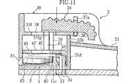
センサカートリッジ1のセンサ保持溝11に収容されたセンサ2を取り出すには、図11に示すように、グリップ部31を握持しつつ、一対の板バネ部材46により上方に付勢されている操作体34を押下する。このとき、操作体34の側面のガイド用突起36は、ガイド溝37のうちの垂直方向に延びる第1の部分37aをスライドしている。次に、図12に示すように、操作体34を装置の前方へスライドさせる。このとき、ガイド用突起36は、ガイド溝37のうちの水平方向に延びる第2の部分37bをスライドしている。ガイド用突起36がガイド溝37の第2の部分37bに位置する限りにおいて、操作体34が復帰位置に戻ることはなく、押下状態が維持される。
【0056】
図11に表れているように、操作体34を押下すると、これに連動して、カッタ43がセンサカートリッジ1におけるセンサ保持溝11のカッタ導入部11bに進入する。このとき、カッタ43は、センサ保持溝11の上面開口部および前面開口部を封止するシート状封止体12を破断する。これと同時に、このような操作体34の押下により、操作体34が具備する押動体40が、封止体12を突き破って当該センサ保持溝11の押動体導入部11cに進入する。押動体導入部11cは、センサ収容部11aに対してカートリッジ背面側で隣接かつ連通しているから、図12に示すように操作体34を前方にスライドさせると、押動体40は押動体導入部11cからセンサ収容部11aに入り込み、センサ2を前方に向けて押動する。その結果、センサ2の一部は、センサ保持溝11の前面における開口部を通り抜け、そして、当該開口部に対面する前部壁31aのセンサ取り出し孔33がから突出する。端子部24b,25bが装置の前方側に位置するようにセンサ保持溝11内にセンサ2を装填しておく場合、上述の操作を経ると、センサ2の端子部24b,25bがセンサ取り出し孔33から突き出ることとなる。従ってユーザは、この状態において、センサ2の端子部24b,25b形成箇所を測定装置の所定箇所に挿入すれば、センサ2を直接指先で触れることなく、例えば血糖値測定などの所定の測定を行うことができる。
【0057】
操作体34を前進位置から後退位置へ戻すと、一対の板バネ部材46の付勢力により操作体34が押下レベルから復帰レベルに復帰する。すると、送り溝13およびピン状駆動体44からなる送り機構により、図3および3aを参照して上述したように、センサカートリッジ1は所定方向に一定のピッチLだけ送られる。本実施形態においては、センサ保持溝11も一定ピッチLで配設されているので、センサカートリッジ1が所定方向にピッチLだけ送られると、操作体34が備えるカッタ43の直下には、未だ破断されていない封止体12により密封されているセンサ保持溝11が配置されることとなる。これによって、次のセンサ2の取り出し操作に備えられる。
【0058】
このように、上記構成のセンサ供給装置3によれば、簡単な操作により、ユーザすなわち患者が全くセンサ2に触れることなく、センサカートリッジ1の各センサ保持溝11内のセンサ2を適正に取り出し、測定装置に取り付けることができる。このとき、センサ2に対して作用する力学的負担が少ないため、センサ2自体にそれほどの剛性は要求されない。従って、センサ2を必要に応じてより小型化する場合であっても、差し支えない。
【0059】
図13〜図15は、本発明の第3の側面に係る測定装置5を示している。
【0060】
この測定装置5は、測定装置5の本体部50と、上述の本発明の第2の側面に係るセンサ供給装置3とを含み、本体部50はセンサ供給装置3の握部内に構成されている。本体部50の表面には、LCDなどの表示部51が設けられており、この表示部51には、センサ2によって行われる測定の結果が表示される。
【0061】
測定装置5に内蔵されるセンサ供給装置3の構成は、図7ないし図12を参照して上に説明したのと同様の構造を含み、センサカートリッジ1から押し出されたセンサ2がセンサ取出し孔33から突出した状態のままでで測定を行うために、更に以下の構成を備える。但し、センサカートリッジ1内に装填されるセンサ2は、本測定装置5においては、図14に示すように、端子部24b,25bが装置の後方側に位置するように、センサカートリッジ1に装填されている。
【0062】
カートリッジ装填部30の前部壁31aにおける取り出し孔33には、図14および図15に詳示するように、カートリッジ1からセンサ2が突出させられた状態において、このセンサ2の端子部24b,25bに導通接触し得る測定装置5側の端子52が備えられている。センサ2上の端子部24b,25bの装置側端子52への接触を確実にするために、センサ2のスペーサ板21およびカバー板23は短くしてもよい。
【0063】
センサ供給装置3に関し、他の構成はすでに説明したのと同様であるので、ここでの詳しい説明は省略する。
【0064】
体液の測定にあたっては、前述と同様に、操作体34を押下した上で前方にスライドさせることにより、センサカートリッジ1内のセンサ2を押し出す。このとき、図13に示すように、センサ2の先端部分が装置の前部壁31aのセンサ取り出し孔33から突出し、センサ2の基端側の端子部24b,25bは、図15に示すように、装置側端子52に導通状態となる。
【0065】
ユーザないし患者は、センサ2の先端の検体付着部に例えばランセットを用いて皮膚に出液させた血液を接触させる。この血液の一部は毛管現象によってセンサ2の体液通路22に導入される。センサ2内では、反応試薬が血液に溶解して酵素反応および電気化学反応が起こり、作用極24aに陽極電流が発生する。この陽極電流は測定装置側の端子52を通じて測定装置5内の回路に導かれ、所定の検量線を用いて換算された血糖値等の測定結果が表示部51に表示される。
【0066】
測定が終わると、センサ2は引き抜かれて破棄され、操作体34は復帰レベルに戻される。この際、上述の送り機構により、センサカートリッジ1がステップ送りされ、次の測定に備えられる。
【0067】
このように、本発明の第3の側面に係る測定装置5によれば、患者は、簡単な操作により、センサ2に全く触れることなく、所定の体液測定を行うことができる。
【0068】
本発明の範囲は上述した実施形態に限定されるものではない。センサ保持溝の形状は、所定のセンサに応じて適宜変更可能である。また、センサカートリッジ本体部の背面に設けられる送り溝は、可動体のピン状駆動体の上下動に応じてカートリッジを1ステップずつ送り可能であれば、他の形態でもよい。
【図面の簡単な説明】
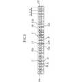
【図1】 図1は、本発明に係るセンサカートリッジの一例の斜視図である。
【図2】 図2は、図1に示すセンサカートリッジの平面図である。
【図3】 図3は、図1に示すセンサカートリッジの背面図である。
【図3a】 図3aは、図3に示した送り溝の起伏を説明するための図である。
【図4】 図4は、図1のIV−IV線に沿う断面図である。
【図5】 図5は、本発明のセンサカートリッジに収容されるセンサの一例を示す斜視図である。
【図6】 図6は、図5に示すセンサの分解斜視図である。
【図7】 図7は、本発明に係るセンサ供給装置の一例の斜視図である。
【図8】 図8は、図7に示すセンサ供給装置の側面図である。
【図9】 図9は、図8のIX−IX線に沿う断面図であり、操作体が復帰レベルに位置する状態を示す。
【図10】 図10は、図9のX−X線に沿う断面図であり、操作体が復帰レベルに位置する状態を示す。
【図11】 図11は、図9のX−X線に沿う断面図であり、操作体が押下レベルにおける後退位置に位置する状態を示す。
【図12】 図12は、図9のX−X線に沿う断面図であり、操作体が押下レベルにおける前進位置に位置する状態を示す。
【図13】 図13は、本発明に係る測定装置の一例の斜視図である。
【図14】 図14は、図13に示す測定装置のセンサ取出し孔付近を示す拡大断面図である。
【図15】 図15は、図14のXV−XV線に沿う断面図である。[0001]
【Technical field】
The present invention relates to a sensor cartridge for housing a sensor used for measuring the concentration of a specific substance contained in a body fluid such as glucose contained in blood. The present invention also relates to a sensor supply device for taking out a sensor from such a sensor cartridge, and a measuring device including such a sensor cartridge.
[0002]
[Background]
In the treatment of diabetes, it is necessary to keep the concentration of glucose (hereinafter referred to as “blood glucose level”) in the blood of the patient within a normal range, and blood glucose level management by the patient himself is an important treatment method. In particular, in the treatment of insulin-dependent diabetes, the blood glucose level measurement is indispensable for the patient because the patient himself / herself must maintain the blood glucose level within a normal range by injecting insulin.
[0003]
Portable blood glucose level measuring devices that can be used by patients themselves to measure blood glucose levels are already on the market. For example, Japanese Patent Application Laid-Open No. 4-357542 discloses such a blood glucose level measuring apparatus. A blood glucose level measuring apparatus generally includes an apparatus main body and a disposable sensor (test piece) attached to the apparatus main body during use. In this sensor, an enzyme electrode including an electrode part and a reaction part in contact with the electrode part is formed. When blood as a specimen is brought into contact with a predetermined part of the sensor, a part of the blood is drawn into the reaction part by capillary action, and an enzyme reaction and an electrochemical reaction proceed in this reaction part. As a result, an anodic current is generated in the electrode part in contact with the reaction part. This anode current is converted into a blood glucose level by an arithmetic circuit provided in the apparatus body, and the calculation result is displayed on the display unit.
[0004]
In a sensor having such an enzyme electrode, a so-called biosensor, when exposed to air for a long time, the reagent contained in the reaction part deteriorates by absorbing moisture in the air, and an accurate measurement value is obtained. It becomes impossible. Therefore, this type of sensor is provided to the patient in a sealed state packaged with an aluminum laminate film or the like. In this case, when measuring the blood glucose level, the patient must first tear the laminate film by hand, and then remove the sensor from the laminate film packaging and attach it to the measuring device. At this time, the patient is required to appropriately perform the above-described operation without touching the enzyme electrode portion or the specimen contact portion of the sensor, which gives psychological pressure to the patient. This is especially true for children, the elderly, adults who are aware that their hands are not very dexterous, or patients with visual impairments. In addition, since this type of measuring apparatus tends to be configured so that appropriate measurement can be performed with as little sample amount as possible, the size of sensors has recently become smaller and smaller. As a result, it has become increasingly difficult for patients to properly handle the sensors.
[0005]
As a sealing form of the sensor, in addition to the packaging of the individual sensors by the laminate film as described above, for example, there is a collective encapsulation of a plurality of sensors by a can with a lid. According to this, the patient must open the can lid, take out a piece of sensor and attach it to the device before measuring the blood glucose level. In this case, every time the lid of the can is opened, all the sensors inside the can are exposed to air. In addition, the ease of handling is not so much improved as compared to packaging with a laminate film, and the handling of the sensor becomes difficult as the sensor becomes smaller.
[0006]
Japanese Patent Application Laid-Open No. 6-308115 discloses another sealing form of a sensor using a sensor cartridge. The sensor cartridge is provided with a plurality of chambers, and a sensor is accommodated in each chamber. More specifically, each chamber of the sensor cartridge has a cylindrical shape with both ends open, and both ends of each chamber are sealed with a foil-shaped sealing body in a state where the sensor is accommodated in each chamber. Yes. This sensor cartridge is attached to a predetermined supply device, and a sensor is pushed out from the other end side of each chamber by inserting a protruding rod provided in the supply device from one end side to the other end side of each chamber.
[0007]
According to such a configuration, it is not necessary for the patient who is a user to manually peel off the sealing body of each chamber of the sensor cartridge, so that the handling becomes easier as compared with the above-described embodiment. However, there are still the following problems.
[0008]
First, since the sensor pushed by the ejection rod must break through the sealing body that seals the end of each chamber, the type of material constituting the sensor body is limited to a certain point from the viewpoint of rigidity. As a result, the sensor can be prevented from being reduced in size and thickness.
[0009]
Second, the sensor cartridge must be inserted into each cylindrical chamber when the sensor is accommodated, and both ends of each chamber must be separately sealed with a sealing body, which makes the manufacture of the sensor cartridge complicated. It becomes.
[0010]
DISCLOSURE OF THE INVENTION
The present invention aims to eliminate or alleviate the above-mentioned problems. Specifically, an object of the present invention is to provide a sensor cartridge in which a sensor packaged in an airtight state can be taken out by a simple operation and is relatively easy to manufacture. It is another object of the present invention to provide a sensor supply device including such a sensor cartridge and a measurement device including such a sensor cartridge.
[0011]
According to a first aspect of the present invention, there is provided a sensor cartridge used by being mounted on a sensor supply device body. This sensor cartridge includes a cartridge body and a sealing body. The cartridge body has an upper surface, a front surface continuous with the upper surface, and a plurality of sensor holding grooves. Each of the sensor holding grooves is formed on the front surface with a first opening formed on the upper surface. Connect to 1 openingContinued And a second opening. The sealing body includes first and second openings in a state where the sensor is loaded in the sensor holding groove.Across these Is blocked.
[0012]
Preferably, the sensor holding groove includes a sensor housing portion for housing the sensor and a pusher introduction portion for receiving the pusher included in the sensor supply device main body. The sensor housing portion communicates with the first and second openings. The pusher introducing portion communicates with the first opening and is continuous with the sensor housing portion so as to face the second opening.
[0013]
Preferably, the sensor holding groove includes a sensor accommodating portion for accommodating the sensor and a cutter introducing portion for receiving the cutter portion included in the sensor supply device main body, and the sensor accommodating portion and the cutter introducing portion include The first and second openings communicate with each other and are continuous with each other.
[0014]
Preferably, the cutter introduction part is formed deeper in the thickness direction of the sensor cartridge than the sensor housing part.
[0015]
Preferably, the front surface is continuous with the upper surface via a rounded portion.
[0016]
Preferably, the sensor cartridge further includes a back surface opposed to the front surface, and a pin member included in the sensor supply device main body is engaged with the back surface, and the sensor cartridge is arranged at a constant pitch in conjunction with one reciprocation of the pin member. A feed groove for feeding by is formed.
[0017]
Preferably, the feed groove includes a plurality of first groove portions each extending in the thickness direction of the sensor cartridge, and a second groove portion extending between an intermediate portion of a certain first groove portion and an upper end portion of the first groove portion adjacent thereto. Including.
[0018]
Preferably, a convex portion for guiding a pin member that moves upward in the first groove portion to the second groove portion is provided in an intermediate portion of the first groove portion.
[0019]
Preferably, the second groove portion is provided with a convex portion for preventing the pin member from entering the second groove portion from the upper end portion of the first groove portion.
[0020]
Preferably, the plurality of sensor holding grooves are provided at a constant pitch.
[0021]
According to the 2nd side surface of this invention, the sensor supply apparatus containing a sensor cartridge and a pushing body is provided. The sensor cartridge includes a cartridge body and a sealing body, and accommodates a plurality of sensors. The pusher can move up and down and can move back and forth, and pushes one of the plurality of sensors. The cartridge body has an upper surface, a front surface continuous with the upper surface, and a plurality of sensor holding grooves. Each of the sensor holding grooves is formed on the front surface with a first opening formed on the upper surface. Connect to 1 openingContinued And a second opening. The sealing body includes first and second openings in a state where the sensor is loaded in the sensor holding groove.Across these Is blocked. The sensor holding groove includes a sensor accommodating portion for accommodating the sensor and a pusher introducing portion for receiving the pusher. The sensor housing portion communicates with the first and second openings, and the pusher introduction portion communicates with the first opening and faces the second opening and is continuous with the sensor housing portion. .
[0022]
Preferably, a cutter part for breaking through the sealing body is further included, and the sensor holding groove includes a cutter introduction part for receiving the cutter part, and the cutter introduction part communicates with the first and second openings. And is continuous with the sensor housing portion.
[0023]
Preferably, the cartridge main body further includes a pin member, and the cartridge main body portion has a back surface facing the front surface. The pin member is engaged with the back surface, and the sensor cartridge is moved in conjunction with one reciprocation of the pin member. Feed grooves for feeding at a constant pitch are formed.
[0024]
Preferably, it further includes an operating body that can move up and down and can move back and forth, and the pusher, the cutter unit, and the pin member move up and down in conjunction with the up and down movement of the operating body, The pusher moves back and forth.
[0025]
Preferably, it further includes a spring member for urging the operating body upward.
[0026]
According to a third aspect of the present invention, a measuring device is provided. This measuring apparatus includes a plurality of sensors each including a base end portion provided with a specimen attaching portion, a reaction portion, and a sensor terminal, a cartridge main body portion, and a sealing body, and houses a plurality of sensors. An arithmetic circuit that includes a cartridge, a pusher that can move up and down and that can move back and forth, and a circuit terminal, and that performs a calculation based on a current generated in the reaction unit Including. The cartridge body has an upper surface, a front surface continuous with the upper surface, and a plurality of sensor holding grooves. Each of the sensor holding grooves is formed on the front surface with a first opening formed on the upper surface. Connect to 1 openingContinued And a second opening. The sealing body includes first and second openings in a state where the sensor is loaded in the sensor holding groove.Across these Is blocked. The sensor holding groove includes a sensor accommodating portion for accommodating the sensor and a pusher introducing portion for receiving the pusher. The sensor housing portion communicates with the first and second openings, and the pusher introduction portion communicates with the first opening and faces the second opening and is continuous with the sensor housing portion. . The sensor is housed in the sensor housing portion so that the specimen adhering portion faces the second opening. A circuit terminal is provided so as to come into contact with the sensor terminal of the sensor when the specimen adhering portion is exposed to the outside of the apparatus by being pushed by the pusher.
[0027]
Preferably, a cutter part for breaking through the sealing body is further included, and the sensor holding groove includes a cutter introduction part for receiving the cutter part, and the cutter introduction part communicates with the first and second openings. And is continuous with the sensor housing portion.
[0028]
Preferably, the cartridge main body further includes a pin member, and the cartridge main body portion has a back surface facing the front surface. The pin member is engaged with the back surface, and the sensor cartridge is moved in conjunction with one reciprocation of the pin member. Feed grooves for feeding at a constant pitch are formed.
[0029]
Preferably, it further includes an operating body that can move up and down and move back and forth, and a movable body that can move up and down together with the operating body, and the movable body is provided with a pin member.
[0030]
According to a fourth aspect of the present invention, another sensor cartridge is provided. This sensor cartridge includes an upper surface, a cartridge main body including a plurality of sensor holding grooves each having an opening formed in the upper surface, and a sealing body that closes the opening. Each of the sensor holding grooves includes a sensor accommodating portion for accommodating the sensor and a cutter introducing portion for receiving a cutter body for breaking through the sealing body, and the sensor accommodating portion and the cutter introducing portion include an opening portion. Are continuous with each other.
[0031]
Other features and advantages of the present invention will become more apparent from the detailed description given below with reference to the drawings.
[0032]
DETAILED DESCRIPTION OF THE INVENTION
Hereinafter, preferred embodiments of the present invention will be described with reference to the drawings.
[0033]
1 to 4 show an example of a
[0034]
The
[0035]
The cartridge
[0036]
As shown in FIG. 4, the strip-shaped
[0037]
As shown in FIG. 3, a
[0038]
FIG. 3 a is a view for explaining undulations along the pin path in the
[0039]
Thus, when the pin-like drive body of the sensor supply device reciprocates once in the thickness direction of the
[0040]
The
[0041]
5 and 6 show an example of the
[0042]
Working electrode putterIs The rectangular working
[0043]
The
[0044]
The front end of the
[0045]
In the case where the
[0046]
FIGS. 7-12 shows an example of the
[0047]
The
[0048]
The operating
[0049]
On the lower surface of the
[0050]
A
[0051]
As well represented in FIG. 9, a pair of support bars 45 extending upward are integrally formed on the upper surface of the horizontal
[0052]
As shown well in FIG. 10, the other end of a pair of
[0053]
The above
[0054]
First, the
[0055]
[0056]
As shown in FIG. 11, when the operating
[0057]
When the operating
[0058]
As described above, according to the
[0059]
13 to 15 show the third embodiment of the present invention.side The measuring apparatus 5 which concerns on is shown.
[0060]
The measuring device 5 includes a
[0061]
The structure of the
[0062]
As shown in detail in FIGS. 14 and 15, in the state where the
[0063]
Since the other configuration of the
[0064]
In the measurement of the body fluid, the
[0065]
The user or patient brings the blood discharged from the skin into contact with the specimen attachment portion at the tip of the
[0066]
When the measurement is finished, the
[0067]
As described above, according to the measuring device 5 according to the third aspect of the present invention, the patient can perform the sensor operation with a simple operation.2 A predetermined body fluid measurement can be performed without touching at all.
[0068]
The scope of the present invention is not limited to the embodiment described above. The shape of the sensor holding groove can be appropriately changed according to a predetermined sensor. Further, the feed groove provided on the back surface of the sensor cartridge main body may have another form as long as the cartridge can be fed step by step in accordance with the vertical movement of the pin-like drive body of the movable body.
[Brief description of the drawings]
FIG. 1 is a perspective view of an example of a sensor cartridge according to the present invention.
FIG. 2 is a plan view of the sensor cartridge shown in FIG.
FIG. 3 is a rear view of the sensor cartridge shown in FIG. 1;
FIG. 3a is a view for explaining the undulation of the feed groove shown in FIG. 3;
4 is a cross-sectional view taken along line IV-IV in FIG. 1. FIG.
FIG. 5 is a perspective view showing an example of a sensor housed in the sensor cartridge of the present invention.
FIG. 6 is an exploded perspective view of the sensor shown in FIG.
FIG. 7 is a perspective view of an example of a sensor supply device according to the present invention.
FIG. 8 is a side view of the sensor supply device shown in FIG. 7;
FIG. 9 is a cross-sectional view taken along the line IX-IX in FIG. 8, showing a state where the operating body is located at the return level.
FIG. 10 is a cross-sectional view taken along line XX of FIG. 9, showing a state where the operating body is positioned at the return level.
FIG. 11 is a cross-sectional view taken along line XX of FIG. 9 and shows a state where the operating body is located at the retracted position at the pressing level.
12 is a cross-sectional view taken along line XX of FIG. 9, showing a state where the operating body is positioned at the forward movement position at the pressing level.
FIG. 13 is a perspective view of an example of a measuring apparatus according to the present invention.
14 is an enlarged cross-sectional view showing the vicinity of a sensor take-out hole of the measuring apparatus shown in FIG.
FIG. 15 is a cross-sectional view taken along line XV-XV in FIG.
Claims (20)
Translated fromJapaneseカートリッジ本体部と封止体とを含み、
上記カートリッジ本体部は、上面と、これに連続する前面と、複数のセンサ保持溝とを有し、上記センサ保持溝の各々は、上記上面に形成された第1の開口部と、上記前面に形成され、上記第1の開口部に連続する第2の開口部とを含み、上記封止体は、上記センサ保持溝にセンサが装填されている状態で上記第1および第2の開口部に跨がってこれらを閉塞している、センサカートリッジ。A sensor cartridge used by being mounted on a sensor supply device body,
Including a cartridge body and a sealing body,
The cartridge main body has an upper surface, a front surface continuous with the upper surface, and a plurality of sensor holding grooves. Each of the sensor holding grooves has a first opening formed on the upper surface and a front surface. is formed, and a second opening forconnection with the said first opening, said sealing body, said first and second openings in a state where the sensor in the sensor holding groove is loadedA sensor cartridge that closes them.
上記第2溝部へ導くための凸部が設けられている、請求項7に記載のセンサカートリッジ。The sensor cartridge according to claim 7, wherein a convex portion for guiding a pin member that moves upward in the first groove portion to the second groove portion is provided at an intermediate portion of the first groove portion.
上下動可能かつ前後動可能な、上記複数のセンサのうちの1つを押動するための押動体と、を含むセンサ供給装置であって、
上記カートリッジ本体部は、上面と、これに連続する前面と、複数のセンサ保持溝とを有し、上記センサ保持溝の各々は、上記上面に形成された第1の開口部と、上記前面に形成され、上記第1の開口部に連続する第2の開口部とを含み、上記封止体は、上記センサ保持溝にセンサが装填されている状態で上記第1および第2の開口部に跨がってこれらを閉塞しており、
上記センサ保持溝は、上記センサを収容するためのセンサ収容部と、上記押動体を受容するための押動体導入部とを含み、上記センサ収容部は、上記第1および第2の開口部に連通し、上記押動体導入部は、上記第1の開口部に連通し、且つ上記第2の開口部に対向して上記センサ収容部に連続している、センサ供給装置。A sensor cartridge containing a plurality of sensors, including a cartridge body and a sealing body;
A pusher for pushing and moving one of the plurality of sensors capable of moving up and down and moving back and forth,
The cartridge main body has an upper surface, a front surface continuous with the upper surface, and a plurality of sensor holding grooves. Each of the sensor holding grooves has a first opening formed on the upper surface and a front surface. is formed, and a second opening forconnection with the said first opening, said sealing body, said first and second openings in a state where the sensor in the sensor holding groove is loaded To blockthese ,
The sensor holding groove includes a sensor housing portion for housing the sensor and a pusher introduction portion for receiving the pusher, and the sensor housing portion is formed in the first and second openings. The sensor supply device, wherein the pusher introduction part communicates with the first opening and is continuous with the sensor housing so as to face the second opening.
カートリッジ本体部と封止体とを含み、上記複数のセンサを収容するセンサカートリッジと、
上下動可能かつ前後動可能な、上記複数のセンサのうちの1つを押動するための押動体と、
回路端子を含み、上記反応部で発生する電流に基づいて演算を実行する演算回路と、を含む測定装置であって、
上記カートリッジ本体部は、上面と、これに連続する前面と、複数のセンサ保持溝とを有し、上記センサ保持溝の各々は、上記上面に形成された第1の開口部と、上記前面に形成され、上記第1の開口部に連続する第2の開口部とを含み、上記封止体は、上記センサ保持溝にセンサが装填されている状態で上記第1および第2の開口部に跨がってこれらを閉塞しており、
上記センサ保持溝は、上記センサを収容するためのセンサ収容部と、上記押動体を受容するための押動体導入部とを含み、上記センサ収容部は、上記第1および第2の開口部に連通し、上記押動体導入部は、上記第1の開口部に連通し、且つ上記第2の開口部に対向して上記センサ収容部に連続しており、
上記センサは、上記検体付着部が上記第2の開口部に対向するように上記センサ収容部に収容されており、
上記押動体により押動されて上記検体付着部が本装置の外部に露出したときに上記センサのセンサ端子と接触するように、上記回路端子が設けられている、測定装置。A plurality of sensors each including a base end portion provided with a specimen attaching portion, a reaction portion, and a sensor terminal;
A sensor cartridge containing a plurality of sensors, including a cartridge body and a sealing body;
A pusher for pushing one of the plurality of sensors capable of moving up and down and moving back and forth;
An arithmetic circuit including a circuit terminal and performing an operation based on a current generated in the reaction unit,
The cartridge main body has an upper surface, a front surface continuous with the upper surface, and a plurality of sensor holding grooves. Each of the sensor holding grooves has a first opening formed on the upper surface and a front surface. is formed, and a second opening forconnection with the said first opening, said sealing body, said first and second openings in a state where the sensor in the sensor holding groove is loaded To blockthese ,
The sensor holding groove includes a sensor housing portion for housing the sensor and a pusher introduction portion for receiving the pusher, and the sensor housing portion is formed in the first and second openings. The pusher introduction portion communicates with the first opening and is continuous with the sensor housing portion so as to face the second opening,
The sensor is accommodated in the sensor accommodating portion so that the specimen adhering portion faces the second opening,
A measurement apparatus, wherein the circuit terminal is provided so as to come into contact with a sensor terminal of the sensor when the specimen adhering portion is exposed to the outside of the apparatus by being pushed by the pusher.
上記開口部を閉塞する封止体とを含み、
上記センサ保持溝の各々は、センサを収容するためのセンサ収容部と、上記封止体を突き破るためのカッタ体を受容するためのカッタ導入部とを含み、上記センサ収容部および上記カッタ導入部は、上記開口部に連通し且つ互いに連続しているセンサカートリッジ。A cartridge body including an upper surface and a plurality of sensor holding grooves each having an opening formed in the upper surface;
Including a sealing body for closing the opening,
Each of the sensor holding grooves includes a sensor accommodating portion for accommodating a sensor and a cutter introducing portion for receiving a cutter body for breaking through the sealing body, and the sensor accommodating portion and the cutter introducing portion. Is a sensor cartridge communicating with the opening and continuous with each other.
Applications Claiming Priority (2)
| Application Number | Priority Date | Filing Date | Title |
|---|---|---|---|
| JP2000045773 | 2000-02-23 | ||
| PCT/JP2001/001325WO2001063272A1 (en) | 2000-02-23 | 2001-02-22 | Sensor cartridge, sensor feeder, and measuring instrument |
Publications (1)
| Publication Number | Publication Date |
|---|---|
| JP4621860B2true JP4621860B2 (en) | 2011-01-26 |
Family
ID=18568307
Family Applications (1)
| Application Number | Title | Priority Date | Filing Date |
|---|---|---|---|
| JP2001562187AExpired - Fee RelatedJP4621860B2 (en) | 2000-02-23 | 2001-02-22 | Sensor cartridge, sensor supply device, and measurement device |
Country Status (8)
| Country | Link |
|---|---|
| US (2) | US7470400B2 (en) |
| EP (1) | EP1271136B1 (en) |
| JP (1) | JP4621860B2 (en) |
| CN (1) | CN1304837C (en) |
| AT (1) | ATE443862T1 (en) |
| AU (1) | AU2001234137A1 (en) |
| DE (1) | DE60139988D1 (en) |
| WO (1) | WO2001063272A1 (en) |
Families Citing this family (28)
| Publication number | Priority date | Publication date | Assignee | Title |
|---|---|---|---|---|
| GB0017737D0 (en)* | 2000-07-20 | 2000-09-06 | Hypoguard Limited | Test device |
| WO2003029804A1 (en)* | 2001-09-28 | 2003-04-10 | Arkray, Inc. | Measurement instrument and concentration measurement apparatus |
| JP4256786B2 (en)* | 2002-02-12 | 2009-04-22 | アークレイ株式会社 | measuring device |
| DE20213607U1 (en) | 2002-02-21 | 2003-07-03 | Paul Hartmann AG, 89522 Heidenheim | Blood analyzer for the determination of an analyte |
| JP4318032B2 (en) | 2002-02-28 | 2009-08-19 | アークレイ株式会社 | measuring device |
| JP4332655B2 (en) | 2002-02-28 | 2009-09-16 | アークレイ株式会社 | Measuring device and measuring tool storage case |
| US6881578B2 (en) | 2002-04-02 | 2005-04-19 | Lifescan, Inc. | Analyte concentration determination meters and methods of using the same |
| US7172728B2 (en) | 2002-04-02 | 2007-02-06 | Lifescan, Inc. | Test strip containers and methods of using the same |
| JP4143753B2 (en)* | 2002-04-05 | 2008-09-03 | アークレイ株式会社 | Analysis tool cartridge with take-out mechanism, and set of this and analyzer |
| US7303726B2 (en) | 2002-05-09 | 2007-12-04 | Lifescan, Inc. | Minimal procedure analyte test system |
| US7343188B2 (en) | 2002-05-09 | 2008-03-11 | Lifescan, Inc. | Devices and methods for accessing and analyzing physiological fluid |
| CN100498320C (en)* | 2002-05-23 | 2009-06-10 | 爱科来株式会社 | Analytical tool, analytical device, analytical tool set, and method for manufacturing analytical tool set |
| US7223248B2 (en)* | 2003-08-13 | 2007-05-29 | Lifescan, Inc. | Packaged medical device with a deployable dermal tissue penetration member |
| US8221332B2 (en) | 2003-11-12 | 2012-07-17 | Facet Technologies, Llc | Multi-lancet cartridge and lancing device |
| EP1684634A2 (en)* | 2003-11-12 | 2006-08-02 | Facet Technologies, LLC | Lancing device and multi-lancet cartridge |
| US7377904B2 (en) | 2004-04-16 | 2008-05-27 | Facet Technologies, Llc | Cap displacement mechanism for lancing device and multi-lancet cartridge |
| US7837633B2 (en) | 2004-06-30 | 2010-11-23 | Facet Technologies, Llc | Lancing device and multi-lancet cartridge |
| US20080089812A1 (en)* | 2004-10-29 | 2008-04-17 | Arkray, Inc. | Analyzer, Cartridge, and Analysis Kit |
| EP2426493B1 (en)* | 2005-01-14 | 2018-10-03 | Ascensia Diabetes Care Holdings AG | Test sensor cartridges and sensor-dispensing instruments |
| EP1710567A1 (en)* | 2005-04-08 | 2006-10-11 | Hach Lange GmbH | Sensor cartridge for wastewater analysis |
| EP2152162A1 (en)* | 2007-05-29 | 2010-02-17 | F. Hoffmann-Roche AG | Test element magazine |
| US9517027B2 (en)* | 2009-07-10 | 2016-12-13 | Facet Techonologies, Llc | Advancement mechanism for cartridge-based devices |
| WO2013096268A1 (en) | 2011-12-20 | 2013-06-27 | Bayer Heal Thcare Llc | Linear, cartridge-based glucose measurement system |
| US9097700B2 (en)* | 2011-12-29 | 2015-08-04 | Bayer Healthcare Llc | Glucose measurement system with high-capacity cartridge and capability of more frequent replenishment |
| US9383333B2 (en) | 2012-05-31 | 2016-07-05 | Ascensia Diabetes Care Holdings Ag | Replaceable multistrip cartridge and biosensor meter |
| WO2013180755A1 (en) | 2012-05-31 | 2013-12-05 | Bayer Healthcare Llc | Multistrip cartridge |
| CA2904689A1 (en) | 2013-03-12 | 2014-10-09 | Bayer Healthcare Llc | Test strip meter with a mechanism for pushing the test strip against an optical reader |
| US11281301B2 (en)* | 2016-02-03 | 2022-03-22 | Flicktek Ltd | Wearable controller for wrist |
Citations (4)
| Publication number | Priority date | Publication date | Assignee | Title |
|---|---|---|---|---|
| JPH08262026A (en)* | 1995-03-14 | 1996-10-11 | Bayer Corp | Fluid monitor sensor dispenser |
| JPH08304405A (en)* | 1995-05-05 | 1996-11-22 | Bayer Corp | Device for handling multiple sensors in glucose monitor system |
| JP2000171427A (en)* | 1998-09-29 | 2000-06-23 | Omron Corp | Sample component analyzing system and sensor chip and sensor pack used therefor |
| JP2002314711A (en)* | 2001-04-12 | 2002-10-25 | Hitachi Maxell Ltd | Portable small electrical equipment |
Family Cites Families (12)
| Publication number | Priority date | Publication date | Assignee | Title |
|---|---|---|---|---|
| EP0394312B1 (en) | 1987-11-02 | 1995-07-19 | Biologix Inc. | A portable blood chemistry measuring apparatus |
| JPH0820412B2 (en) | 1990-07-20 | 1996-03-04 | 松下電器産業株式会社 | Quantitative analysis method and device using disposable sensor |
| GB2267231B (en)* | 1992-05-26 | 1996-04-03 | Pall Corp | Filter assembly |
| DE59410388D1 (en) | 1993-04-23 | 2004-10-21 | Roche Diagnostics Gmbh | Floppy disk with test elements arranged in a circle |
| CN1097468A (en)* | 1993-06-30 | 1995-01-18 | 中国科学院武汉病毒研究所 | Measure the double-electrode complex enzyme sensor for ditermining of dextrose plus saccharose simultaneously |
| DE4427363A1 (en)* | 1993-08-03 | 1995-03-09 | A & D Co Ltd | A disposable chemical sensor |
| JP3503082B2 (en) | 1994-07-29 | 2004-03-02 | 松下電器産業株式会社 | High frequency deflection yoke drive circuit |
| CA2170560C (en) | 1995-04-17 | 2005-10-25 | Joseph L. Moulton | Means of handling multiple sensors in a glucose monitoring instrument system |
| JP3382853B2 (en)* | 1998-04-09 | 2003-03-04 | 松下電器産業株式会社 | Body fluid testing device |
| JP3874321B2 (en)* | 1998-06-11 | 2007-01-31 | 松下電器産業株式会社 | Biosensor |
| JP2001033418A (en)* | 1999-07-26 | 2001-02-09 | Matsushita Electric Ind Co Ltd | measuring device |
| JP4357452B2 (en) | 2005-06-02 | 2009-11-04 | テルモ株式会社 | Oxygen concentrator |
- 2001
- 2001-02-22JPJP2001562187Apatent/JP4621860B2/ennot_activeExpired - Fee Related
- 2001-02-22EPEP01906227Apatent/EP1271136B1/ennot_activeExpired - Lifetime
- 2001-02-22ATAT01906227Tpatent/ATE443862T1/ennot_activeIP Right Cessation
- 2001-02-22WOPCT/JP2001/001325patent/WO2001063272A1/enactiveApplication Filing
- 2001-02-22CNCNB018055133Apatent/CN1304837C/ennot_activeExpired - Fee Related
- 2001-02-22DEDE60139988Tpatent/DE60139988D1/ennot_activeExpired - Lifetime
- 2001-02-22USUS10/204,508patent/US7470400B2/ennot_activeExpired - Fee Related
- 2001-02-22AUAU2001234137Apatent/AU2001234137A1/ennot_activeAbandoned
- 2008
- 2008-11-20USUS12/274,912patent/US7790106B2/ennot_activeExpired - Fee Related
Patent Citations (4)
| Publication number | Priority date | Publication date | Assignee | Title |
|---|---|---|---|---|
| JPH08262026A (en)* | 1995-03-14 | 1996-10-11 | Bayer Corp | Fluid monitor sensor dispenser |
| JPH08304405A (en)* | 1995-05-05 | 1996-11-22 | Bayer Corp | Device for handling multiple sensors in glucose monitor system |
| JP2000171427A (en)* | 1998-09-29 | 2000-06-23 | Omron Corp | Sample component analyzing system and sensor chip and sensor pack used therefor |
| JP2002314711A (en)* | 2001-04-12 | 2002-10-25 | Hitachi Maxell Ltd | Portable small electrical equipment |
Also Published As
| Publication number | Publication date |
|---|---|
| EP1271136B1 (en) | 2009-09-23 |
| US7470400B2 (en) | 2008-12-30 |
| WO2001063272A1 (en) | 2001-08-30 |
| EP1271136A1 (en) | 2003-01-02 |
| ATE443862T1 (en) | 2009-10-15 |
| US20090074617A1 (en) | 2009-03-19 |
| US7790106B2 (en) | 2010-09-07 |
| CN1404576A (en) | 2003-03-19 |
| CN1304837C (en) | 2007-03-14 |
| AU2001234137A1 (en) | 2001-09-03 |
| US20030013992A1 (en) | 2003-01-16 |
| EP1271136A4 (en) | 2003-04-02 |
| DE60139988D1 (en) | 2009-11-05 |
Similar Documents
| Publication | Publication Date | Title |
|---|---|---|
| JP4621860B2 (en) | Sensor cartridge, sensor supply device, and measurement device | |
| CN101366633B (en) | Lancet-integrated sensor, measurement device, and biosensor case | |
| US8043231B2 (en) | Lancing unit and lancing apparatus | |
| CN101237815B (en) | Integrated Test System for Monitoring Body Fluids | |
| US7299081B2 (en) | Analyte test device | |
| US8323212B2 (en) | Attachment for body fluid sampling device and method of making the same | |
| EP1541087B1 (en) | Body fluid sampling device | |
| CN102415888A (en) | Blood test apparatus | |
| TW201610433A (en) | Sensor clip for stacked sensor dispensing system, and systems, methods and devices for making and using the same | |
| EP2174593A1 (en) | Blood test device and test method | |
| JP4250692B2 (en) | Body fluid measuring device and wearing body | |
| JP2000116626A5 (en) | ||
| JP2009268755A (en) | Measuring instrument coupled with needle | |
| JP2004033375A (en) | Humor collecting implement | |
| KR101449714B1 (en) | Apparatus for measuring biometric information by using an ejecting button | |
| JP2009160152A (en) | Measuring device with integrated needle |
Legal Events
| Date | Code | Title | Description |
|---|---|---|---|
| A521 | Request for written amendment filed | Free format text:JAPANESE INTERMEDIATE CODE: A523 Effective date:20080131 | |
| A621 | Written request for application examination | Free format text:JAPANESE INTERMEDIATE CODE: A621 Effective date:20080131 | |
| A131 | Notification of reasons for refusal | Free format text:JAPANESE INTERMEDIATE CODE: A131 Effective date:20100706 | |
| A521 | Request for written amendment filed | Free format text:JAPANESE INTERMEDIATE CODE: A523 Effective date:20100831 | |
| TRDD | Decision of grant or rejection written | ||
| A01 | Written decision to grant a patent or to grant a registration (utility model) | Free format text:JAPANESE INTERMEDIATE CODE: A01 Effective date:20100928 | |
| A01 | Written decision to grant a patent or to grant a registration (utility model) | Free format text:JAPANESE INTERMEDIATE CODE: A01 | |
| A61 | First payment of annual fees (during grant procedure) | Free format text:JAPANESE INTERMEDIATE CODE: A61 Effective date:20100930 | |
| R150 | Certificate of patent or registration of utility model | Ref document number:4621860 Country of ref document:JP Free format text:JAPANESE INTERMEDIATE CODE: R150 Free format text:JAPANESE INTERMEDIATE CODE: R150 | |
| FPAY | Renewal fee payment (event date is renewal date of database) | Free format text:PAYMENT UNTIL: 20131112 Year of fee payment:3 | |
| R250 | Receipt of annual fees | Free format text:JAPANESE INTERMEDIATE CODE: R250 | |
| R250 | Receipt of annual fees | Free format text:JAPANESE INTERMEDIATE CODE: R250 | |
| R250 | Receipt of annual fees | Free format text:JAPANESE INTERMEDIATE CODE: R250 | |
| R250 | Receipt of annual fees | Free format text:JAPANESE INTERMEDIATE CODE: R250 | |
| R250 | Receipt of annual fees | Free format text:JAPANESE INTERMEDIATE CODE: R250 | |
| R250 | Receipt of annual fees | Free format text:JAPANESE INTERMEDIATE CODE: R250 | |
| LAPS | Cancellation because of no payment of annual fees |