JP4621039B2 - Disk unit - Google Patents
Disk unitDownload PDFInfo
- Publication number
- JP4621039B2 JP4621039B2JP2005045365AJP2005045365AJP4621039B2JP 4621039 B2JP4621039 B2JP 4621039B2JP 2005045365 AJP2005045365 AJP 2005045365AJP 2005045365 AJP2005045365 AJP 2005045365AJP 4621039 B2JP4621039 B2JP 4621039B2
- Authority
- JP
- Japan
- Prior art keywords
- disk
- drive
- housing
- wiring board
- drawer
- Prior art date
- Legal status (The legal status is an assumption and is not a legal conclusion. Google has not performed a legal analysis and makes no representation as to the accuracy of the status listed.)
- Expired - Fee Related
Links
Images


Classifications
- G—PHYSICS
- G06—COMPUTING OR CALCULATING; COUNTING
- G06F—ELECTRIC DIGITAL DATA PROCESSING
- G06F1/00—Details not covered by groups G06F3/00 - G06F13/00 and G06F21/00
- G06F1/16—Constructional details or arrangements
- G06F1/18—Packaging or power distribution
- G06F1/181—Enclosures
- G—PHYSICS
- G06—COMPUTING OR CALCULATING; COUNTING
- G06F—ELECTRIC DIGITAL DATA PROCESSING
- G06F1/00—Details not covered by groups G06F3/00 - G06F13/00 and G06F21/00
- G06F1/16—Constructional details or arrangements
- G06F1/20—Cooling means
Landscapes
- Engineering & Computer Science (AREA)
- Theoretical Computer Science (AREA)
- Human Computer Interaction (AREA)
- Physics & Mathematics (AREA)
- General Engineering & Computer Science (AREA)
- General Physics & Mathematics (AREA)
- Computer Hardware Design (AREA)
- Power Engineering (AREA)
- Automatic Disk Changers (AREA)
- Cooling Or The Like Of Electrical Apparatus (AREA)
Description
Translated fromJapanese本発明は、ディスク装置に関し、特に、複数のディスクドライブを備えるディスク装置に関する。 The present invention relates to a disk device, and more particularly to a disk device including a plurality of disk drives.
高性能のコンピュータシステムは、一般に、CPU等の上位装置と、磁気ディスク等の2次記憶装置とを備えている。上位装置は、必要なデータを2次記憶装置から随時に読み出すと共に、所定のデータを2次記憶装置に書き込む。2次記憶装置は、一般に、磁気ディスクのほかにも光ディスクのように、ランダムアクセス可能な不揮発性記憶媒体を有するディスク装置である。 A high-performance computer system generally includes a host device such as a CPU and a secondary storage device such as a magnetic disk. The host device reads necessary data from the secondary storage device as needed and writes predetermined data to the secondary storage device. The secondary storage device is generally a disk device having a non-volatile storage medium that can be randomly accessed, such as an optical disk, in addition to a magnetic disk.
近年、ディスク装置は、多数の小型ディスクドライブ(以下、単にドライブという)を備えることにより、記憶容量が増加の傾向にあるが、さらに、その記憶容量を増加しつつ、ディスク装置の小型化が要望されている。すなわち、ドライブの実装密度を高くすることが要望されている。そのために、複数のドライブを筐体内に3次元的に実装するディスク装置が採用された。具体的には、このディスク装置では、複数のドライブを筐体の奥行き方向yに並べて構成されるドライブ列が、筐体の高さ方向zおよび幅方向xに並べられている。 In recent years, a disk device has a tendency to increase the storage capacity by providing a large number of small disk drives (hereinafter simply referred to as drives). Further, the disk device is required to be reduced in size while increasing the storage capacity. Has been. That is, it is desired to increase the mounting density of the drive. For this purpose, a disk device that three-dimensionally mounts a plurality of drives in a housing has been adopted. Specifically, in this disk device, a drive row configured by arranging a plurality of drives in the depth direction y of the casing is arranged in the height direction z and the width direction x of the casing.
しかしながら、このディスク装置に実装されたドライブに障害が発生した場合、障害ドライブを正常ドライブに交換する必要があるため、ディスク装置の内部に(隣接するドライブ列の間に)、ドライブの交換作業を行うための空間が確保されている。そのため、ドライブの実装密度を増加させようとしても限界がある。そこで、従来、筐体の外部でドライブの交換作業ができるディスク装置が提案されている(例えば、特許文献1、特許文献2)。 However, when a failure occurs in a drive installed in this disk device, it is necessary to replace the failed drive with a normal drive, so the drive replacement work must be performed inside the disk device (between adjacent drive trains). Space to do it is secured. For this reason, there is a limit to increasing the mounting density of the drive. Therefore, conventionally, a disk device that can replace a drive outside the casing has been proposed (for example,
特許文献1に開示されたディスク装置は、ドライブを奥行き方向yに2台、かつ、高さ方向zに2台並べて搭載したスロットを高さ方向zに複数備えている。このスロットは、ディスク装置の筐体から引き出すことができるように構成されている。このディスク装置に実装されたドライブに障害が発生した場合、作業者は、まず、障害ドライブが搭載されているスロットを引き出し、筐体の外部で障害ドライブを正常ドライブに交換した後、スロットを筐体に押し戻すこととなる。なお、このディスク装置は、スロットを筐体から引き出した状態でも正常ドライブが連続運転することを想定している。 The disk device disclosed in
また、特許文献2に開示されたディスク装置は、ドライブを奥行き方向yに5台または6台並べたドライブ列が幅方向xに2列配設され、かつ、この2列のドライブ列の間に、配線基板としての電子カード(アダプタ装置)を有するプレートを高さ方向zに複数備えている。このプレートは、ディスク装置の筐体から引き出すことができるように構成されている。したがって、このディスク装置に実装されたドライブに障害が発生した場合にも、作業者は、プレートを引き出すことにより、筐体の外部でドライブの交換作業をすることができる。
しかしながら、特許文献1に開示されたディスク装置においては、スロットが引き出されると、ドライブと、このドライブへ冷却風を送風するためのファンとの間の距離が離れてしまい、冷却効果が低減する。また、この状態のままでは、スロットを引き出すための筐体開口部から空気が流入し冷却風の流れが発散してしまう。従って、このディスク装置は、スロットが引き出された状態では、ドライブを十分に冷却することができない。また、このディスク装置は、ドライブを幅方向xに複数実装することが考慮されていないので、記憶容量を増加させることが難しい。 However, in the disk device disclosed in
また、特許文献2に開示されたディスク装置においては、2列のドライブ列の間隔が、電子カード(アダプタ装置)の基板の幅の長さだけ離れ、かつ、電子カード(アダプタ装置)の基板面とドライブの回転面とが平行に配置されているので、幅方向xのドライブ実装密度が低くなってしまう。 In the disk device disclosed in
そこで、本発明では、前記した問題を解決し、ドライブの実装密度を高めることが可能なディスク装置を提供することを目的とする。
また、ドライブ交換時においても動作中のドライブを冷却可能なディスク装置を提供することを他の目的とする。Accordingly, an object of the present invention is to provide a disk device capable of solving the above-described problems and increasing the mounting density of drives.
Another object of the present invention is to provide a disk device that can cool a drive in operation even when the drive is replaced.
本発明は、前記課題を解決するために創案されたものであり、筐体と、この筐体の奥行き方向および高さ方向に並べられた複数のディスクドライブと、各ディスクドライブの配線基板と、各ディスクドライブの送風手段とを有するディスク装置において、各ディスクドライブは、ディスク回転面が配線基板の基板面に対して垂直となるように配線基板に所定間隔を隔てて接続され、ディスク装置は、複数のディスクドライブ、配線基板、および送風手段を一体にして筐体から引き出す引出部と、引出部が筐体に収納されている状態で視認可能な引出部の前面パネルに設けられ、各ディスクドライブの動作状況を表示する前面表示部と、引出部が筐体から引き出された状態で視認可能な引出部の側面板に設けられ、各ディスクドライブの動作状況を表示する側面表示部と、を備えることを特徴とする。The present invention was devised to solve the above problems, and a housing, a plurality of disk drives arranged in the depth direction and the height direction of the housing, a wiring board of each disk drive, In each disk drive having a blowing means for each disk drive, each disk drive is connected to the wiring board at a predetermined interval so that the disk rotation surface is perpendicular to the board surface of the wiring board. a plurality of diskdrives, wiringboard, anda lead-out portion to drawthe blowing handstage from the housing so as to beintegrated, the lead portion is provided on the front panel of possible lead-out portion visible in the state housed in the housing, The front display unit that displays the operating status of each disk drive, and the side panel of the drawer unit that can be viewed with the drawer unit pulled out from the housing, Characterized in that it anda side display unit for displaying.
このような構成によれば、ディスク装置は、各ディスクドライブと、配線基板と、送風手段とを一体にして筐体から引き出すことができるので、ディスクドライブに障害が発生した場合に、正常なドライブや配線基板を十分に冷却しながら障害ドライブを交換することができる。また、各ディスクドライブは、ディスク回転面が配線基板の基板面に対して垂直となるように配線基板に接続されるので、ドライブの実装密度を高くすることができる。 According to such a configuration, each disk drive, the wiring board, and the air blowing means can be pulled out from the housing integrally with the disk device, so that when a failure occurs in the disk drive, a normal drive The faulty drive can be replaced while the wiring board is sufficiently cooled. In addition, each disk drive is connected to the wiring board so that the disk rotation surface is perpendicular to the board surface of the wiring board, so that the mounting density of the drive can be increased.
また、本発明は、好ましくは、筐体と、この筐体の奥行き方向に複数のディスクドライブを並べて形成した複数のドライブ列と、ドライブ列の配線基板とを有するディスク装置において、各ドライブ列は、筐体の高さ方向および幅方向に所定間隔を隔てて配設され、配線基板は、筐体の幅方向に配設された隣接する2つのドライブ列の間に、配線基板の基板面がディスク回転面に対して垂直となるように配設されると共に、配線基板の両面それぞれにディスクドライブ接続面を有し、ディスク装置は、配線基板およびこの配線基板の両側に配設された少なくとも2つのドライブ列を一体にして筐体から引き出す引出部と、引出部が筐体に収納されている状態で視認可能な引出部の前面パネルに設けられ、各ディスクドライブの動作状況を表示する前面表示部と、引出部が筐体から引き出された状態で視認可能な引出部の側面板に設けられ、各ディスクドライブの動作状況を表示する側面表示部と、を備えるようにしてもよい。かかる構成によれば、ドライブ列を1列ごとに引き出す場合に比べて、引出部に必要な体積が低減できるので、ドライブの実装密度を高くすることができる。Further, the present invention is preferably a disk device having a housing, a plurality of drive rows formed by arranging a plurality of disk drives in the depth direction of the housing, and a wiring board of the drive rows, wherein each drive row is The wiring board is disposed at a predetermined interval in the height direction and the width direction of the housing, and the wiring board has a substrate surface between two adjacent drive rows arranged in the width direction of the housing. while being arranged so as to be perpendicular to the disk rotating surface has a disk drive connection surfaces Both surfaces of the wiring substrate, at leastthe disk device, disposed on both sides of the wiring boardand the
また、本発明は、好ましくは、筐体と、この筐体の奥行き方向に複数のディスクドライブを並べて形成した複数のドライブ列と、ドライブ列の配線基板と、各ディスクドライブの送風手段とを有するディスク装置において、各ドライブ列は、筐体の高さ方向および幅方向に所定間隔を隔てて配設され、配線基板は、筐体の幅方向に配設された隣接する2つのドライブ列の間に、配線基板の基板面がディスク回転面に対して垂直となるように配設されると共に、配線基板の両面それぞれにディスクドライブ接続面を有し、ディスク装置は、配線基板、この配線基板の両側に配設された少なくとも2つのドライブ列および前記送風手段を一体にして前記筐体から引き出す引出部と、引出部が筐体に収納されている状態で視認可能な引出部の前面パネルに設けられ、各ディスクドライブの動作状況を表示する前面表示部と、引出部が筐体から引き出された状態で視認可能な引出部の側面板に設けられ、各ディスクドライブの動作状況を表示する側面表示部と、を備えるようにしてもよい。In addition, the present invention preferably includes a housing, a plurality of drive rows formed by arranging a plurality of disk drives in the depth direction of the housing, a wiring board of the drive rows, and a blowing unit of each disk drive. In the disk device, each drive row is disposed at a predetermined interval in the height direction and the width direction of the housing, and the wiring board is between two adjacent drive rows disposed in the width direction of the housing. to, together with the substrate surface of the wiring board is disposed so as to be perpendicular to the disk rotating surface has a disk drive connection surfaces Both surfaces of the wiring substrate,a disk device, wiringboard, the wiring board at least two columns of drivesand the blowerand the lead-out portion of the handstages and integrally pulled out from thehousing, the front path of possible lead-out portion visible in a state where the lead portion is housed in a housing disposed on opposite sides of theThe front display that displays the operating status of each disk drive and the drawer side panel that is visible when the drawer is pulled out from the housing display the operating status of each disk drive. And a side display unit that performs the above-described operation.
本発明によれば、ドライブの実装密度を高めることができる。 According to the present invention, the mounting density of the drive can be increased.
次に、本発明の実施形態について、適宜図面を参照しながら詳細に説明する。
(第1の実施形態)
図1は、第1の実施形態に係るディスク装置の正面外観図であり、図2は、第1の実施形態に係るディスク装置の背面外観図である。図1に示すように、ディスク装置1は、筐体2の中に、ディスクコントローラ3と、ディスクアレイユニット4と、2台の電源装置5a,5bとを備えている。ここで、筐体2の幅方向をx、奥行き方向をy、高さ方向をzとする。なお、筐体2は、例えば19型ラック(19インチラック)等である。Next, embodiments of the present invention will be described in detail with reference to the drawings as appropriate.
(First embodiment)
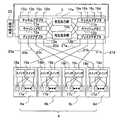
FIG. 1 is a front external view of the disk device according to the first embodiment, and FIG. 2 is a rear external view of the disk device according to the first embodiment. As shown in FIG. 1, the
ディスクコントローラ3は、ディスクアレイユニット4の動作を制御するものであり、その詳細は後記する。
ディスクアレイユニット4は、ディスクコントローラ3の上方に配設され、筐体2の幅方向xに、4個のドロワ(引出部)6a,6b,6c,6dを有している。これらのドロワ6a〜6dは、それぞれ、奥行き方向yに沿って引き出すことができるように構成されている。ドロワ6aは、チャネル7a,7bを介してディスクコントローラ3と接続されている。また、ドロワ6bは、チャネル7c,7dを介してディスクコントローラ3と接続されている。同様に、ドロワ6cも、チャネル7e,7fを介してディスクコントローラ3と接続され、また、ドロワ6dも、チャネル7g,7hを介してディスクコントローラ3と接続されている。なお、チャネル7a〜7hは、ドロワ6a〜6dの引き出しが可能な十分な余長を有している。The
The
電源装置5a,5bは、ディスクコントローラ3の下方で、筐体2の幅方向xに並設されている。この電源装置5a,5bは、図2に示すように、複数の電源ケーブルを介して、各ドロワ6a〜6dとそれぞれ接続されている。これらの電源ケーブルも、ドロワ6a〜6dを引き出しても支障のない余長を有している。これにより、各ドロワ6a〜6dには電源装置5a,5bのいずれか一方から電力が供給される。具体的には、ドロワ6aのコネクタ8aは、電源装置5bのコネクタ9bと接続され、且つ、このドロワ6aのコネクタ8bは、電源装置5aのコネクタ9aと接続されている。このように構成することにより、ドロワ6aには、電源装置5a,5bのいずれか一方から電力が供給される。この場合、電力供給を行わない他方の電源装置は予備として利用される。あるいはドロワ6aには電源装置5a,5bの両方から電力を供給し、ドロワ6a内の後記するディスクドライブ毎に電源装置5a,5bのいずれかを供給元とするようにしてもよい。なお、電源装置5a,5bは、それぞれ電源コネクタ10a,10bを介して主電源に接続されている。 The
図3は、ディスクコントローラの構成を示すブロック図である。
ディスクコントローラ3は、図3に示すように、チャネルアダプタ11a,11bと、キャッシュメモリ12a,12bと、ディスクアダプタ13a,13bとを備えている。
キャッシュメモリ12a,12bは、データ等を一時的に記憶するものである。
チャネルアダプタ11a,11bの詳細な構成と、ディスクアダプタ13a,13bの詳細な構成は、後記する。FIG. 3 is a block diagram showing the configuration of the disk controller.
As shown in FIG. 3, the
The
The detailed configuration of the
チャネルアダプタ11aと、キャッシュメモリ12aと、ディスクアダプタ13aとは、相互結合網14a,14bに接続されている。また、チャネルアダプタ11aは、チャネル15a,15b,15c,15dを介して、CPU等の上位装置(図示せず)と接続されている。
同様に、チャネルアダプタ11bと、キャッシュメモリ12bと、ディスクアダプタ13bとは、相互結合網14a,14bに接続されている。また、チャネルアダプタ11bは、チャネル16a,16b,16c,16dを介して上位装置(図示せず)と接続されている。The
Similarly, the channel adapter 11b, the cache memory 12b, and the
ここで、ディスクコントローラ3に接続されるディスクアレイユニット4の主要な構成について説明する。ディスクアレイユニット4を構成するドロワ6aは、複数のディスクドライブ(以下、単にドライブという)から成るディスクアレイ17aと、これらのドライブを切り替えて2つの入出力ポートに接続するスイッチ18a,19aとを備えている。ディスクアレイ17aを構成するドライブは、入出力ポートを2ポート有するドライブ、例えばファイバチャネルやSAS(Serial Attached SCSI)規格のドライブである。同様に、ドロワ6bは、ディスクアレイ17bと、スイッチ18b,19bとを備えている。また、ドロワ6cは、ディスクアレイ17cと、スイッチ18c,19cとを備えている。さらに、ドロワ6dは、ディスクアレイ17dと、スイッチ18d,19dとを備えている。 Here, the main configuration of the
なお、各ドライブに、1つの入出力ポートを有するSATA(Serial ATA)規格のドライブを使用する場合は、ポート・セレクタを各ドライブに接続してSATA規格のドライブを2ポート化することにより、図3に示したディスクアレイユニット4を構成することが可能である。この場合、スイッチ18a〜18d,19a〜19dとしては、例えばポート・マルチプライヤを利用することができる。また、SAS規格のドライブを使用してディスクアレイユニット4を構成する場合には、スイッチ18a〜18d,19a〜19dとしては、例えばエキスパンダを利用することができる。また、ファイバチャネル・アービトレイテッド・ループ(FC−AL)によるデュアル・ループ接続によりディスクアレイユニット4を構成する場合には、スイッチ18a〜18d,19a〜19dとしては、ループ・スイッチを利用することができる。 When a SATA (Serial ATA) standard drive having one input / output port is used for each drive, a port selector is connected to each drive so that two SATA standard drives are provided. The
前記した構成のディスクアレイユニット4とディスクコントローラ3とは、次のようにして接続されている。すなわち、ディスクコントローラ3のディスクアダプタ13aは、ディスクチャネル20aとスイッチ18aとを介してディスクアレイ17aに接続されている。このディスクアダプタ13aは、ディスクチャネル20bとスイッチ18bとを介してディスクアレイ17bに接続されている。また、ディスクアダプタ13aは、ディスクチャネル20cとスイッチ18cとを介してディスクアレイ17cに接続されている。さらに、ディスクアダプタ13aは、ディスクチャネル20dとスイッチ18dとを介してディスクアレイ17dに接続されている。 The
同様に、ディスクアダプタ13bは、ディスクチャネル21aとスイッチ19aとを介してディスクアレイ17aに接続されている。このディスクアダプタ13bは、ディスクチャネル21bとスイッチ19bとを介してディスクアレイ17bに接続されている。また、ディスクアダプタ13bは、ディスクチャネル21cとスイッチ19cとを介してディスクアレイ17cに接続されている。さらに、ディスクアダプタ13bは、ディスクチャネル21dとスイッチ19dとを介してディスクアレイ17dに接続されている。 Similarly, the
また、ディスクコントローラ3のチャネルアダプタ11a,11bおよびディスクアダプタ13a,13bは、保守端末22と接続されている。この保守端末22は、ディスクコントローラ3に設定情報を入力したり、ディスク装置1の稼働状況をモニタしたりするものである。 The
次に、チャネルアダプタ11aの構成を図4に示す。図4に示すように、チャネルアダプタ11aは、ホストチャネルインターフェイス23と、キャッシュメモリインターフェイス24と、ネットワークインターフェイス25と、プロセッサ26と、ローカルメモリ27と、プロセッサ周辺制御部28とを備えている。 Next, the configuration of the
ホストチャネルインターフェイス23は、チャネル15a〜15dに接続するためのものである。このホストチャネルインターフェイス23は、チャネル15a〜15d上のデータ転送プロトコルと、ディスクコントローラ3内部のデータ転送プロトコルとの間の変換を行う。
キャッシュメモリインターフェイス24は、相互結合網14a,14bに接続するためのものである。なお、このキャッシュメモリインターフェイス24と、ホストチャネルインターフェイス23との間は、信号線29によって接続されている。
ネットワークインターフェイス25は、保守端末22に接続するためのものである。The
The
The
プロセッサ26は、上位装置(図示せず)とキャッシュメモリ12aとの間でのデータ転送を制御するものである。
ローカルメモリ27は、プロセッサ26が参照する各種のテーブルや実行すべきソフトウェアを格納するものである。なお、プロセッサ26が参照する各種のテーブルの設定や変更は、保守端末22により実行される。
プロセッサ周辺制御部28は、ホストチャネルインターフェイス23と、キャッシュメモリインターフェイス24と、ネットワークインターフェイス25と、プロセッサ26と、ローカルメモリ27とを相互に接続するためのものである。
チャネルアダプタ11bは、ホストチャネルインターフェイス23が、チャネル16a〜16dに接続されている。その他の構成は、図4に示したチャネルアダプタ11aと同一の構成なので、説明を省略する。The
The
The processor
In the channel adapter 11b, the
次に、ディスクアダプタ13aの構成を図5に示す。図5に示すように、ディスクアダプタ13aは、キャッシュメモリインターフェイス24と、ディスクチャネルインターフェイス31と、ネットワークインターフェイス25と、プロセッサ26Aと、ローカルメモリ27と、プロセッサ周辺制御部28Aとを備えている。このうち、プロセッサ26Aと、ディスクチャネルインターフェイス31と、プロセッサ周辺制御部28Aとを除いた他の構成要素が、図4に示したチャネルアダプタ11aと同一であるので、これと同一の構成には、同一の符号を付し、説明を省略する。 Next, the configuration of the
プロセッサ26Aは、キャッシュメモリ12aとディスクアレイ17a〜17dとの間でのデータ転送を制御するものである。
ディスクチャネルインターフェイス31は、ディスクチャネル20a〜20dに接続するためのものである。このディスクチャネルインターフェイス31は、ディスクコントローラ3内部のデータ転送プロトコルと、ディスクチャネル20a〜20d上のデータ転送プロトコル、例えば、FCP−SCSIとの間の変換を行う。なお、このディスクチャネルインターフェイス31と、キャッシュメモリインターフェイス24との間は、信号線32によって接続されている。The
The
プロセッサ周辺制御部28Aは、キャッシュメモリインターフェイス24と、ディスクチャネルインターフェイス31と、ネットワークインターフェイス25と、プロセッサ26Aと、ローカルメモリ27とを相互に接続するためのものである。
ディスクアダプタ13bは、ディスクチャネルインターフェイス31が、ディスクチャネル21a,21b,21c,21dに接続されている。その他の構成は、図5に示したディスクアダプタ13aと同一の構成なので説明を省略する。The processor
In the
なお、図3に示したディスクコントローラ3は、チャネルアダプタ11a,11bと、ディスクアダプタ13a,13bとを含むものとして説明したが、これは一例であって、他の構成であってもよい。例えば、チャネルアダプタ11a,11bの行う処理と、ディスクアダプタ13a,13bの行う処理とを、両方とも実行できる1つの制御部を設けるようにしてもよい。また、チャネルアダプタ11a,11bと、ディスクアダプタ13a,13bとから、プロセッサ26を分離して独立させて、この独立した1つのプロセッサと、各インターフェイス23,24,25,31等とをスイッチで相互に接続するようにしてもよい。 The
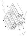
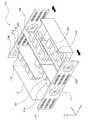
次に、ディスクアレイユニット4の構造を、図6を参照して説明する。図6は、ディスクアレイユニットの内部を示す斜視図である。ディスクアレイユニット4を構成するドロワ6aは、ディスクアレイ17aのほかに、配線基板38aと、ファン39aとを備えている。同様に、ドロワ6bは、ディスクアレイ17bのほかに、配線基板38bと、ファン39bとを備えている。また、ドロワ6cは、ディスクアレイ17cのほかに、配線基板38cと、ファン39cとを備えている。さらに、ドロワ6dは、ディスクアレイ17dのほかに、配線基板38dと、ファン39dとを備えている。なお、各ドロワ6a〜6dには、図6には示されていないが、ドロワフレームや、このドロワフレームに固定された側面板および天板等が設けられている。詳細は後記する。 Next, the structure of the
ディスクアレイ17a〜17dは、筐体2の奥行き方向yおよび高さ方向zに所定間隔を隔てて複数のドライブを並べて構成されている。各ドライブは、ディスク回転面が配線基板38a〜38dの基板面に対して垂直となるように、配線基板38a〜38dに接続されている。本実施の形態では、ディスクアレイ17a〜17dにそれぞれ属する8台のドライブは、ディスクの回転面が水平方向となるようにして、奥行き方向yに4台、高さ方向zに2段配設されている。すなわち、ディスクアレイ17a〜17dは、それぞれ奥行き方向yに4台配設されたドライブ列を高さ方向zに2段有している。そして、ディスクアレイユニット4全体としては、前記したドライブ列を幅方向xに4列有している。 The
そして、ディスクアレイ17a〜17dに属するドライブ(ドロワ6a〜6dに属するドライブ)においては、異なるドロワに属するドライブを組み合わせて、データ冗長構造、すなわち、RAID(Redundant Array of Independent Disk)の論理グループが構成されている。例えば、ドロワ6aに属するドライブと、ドロワ6bに属するドライブとを組み合わせることにより、RAID1が構成される。具体的には、ディスク装置1では、ドロワ6aに属する複数のドライブはデータ格納用ドライブとし、ドロワ6bに属するドライブは、データ格納用ドライブと対をなす冗長ドライブ(予備ドライブ)としている。そして、ディスク装置1は、同一データを、データ格納用ドライブと冗長ドライブとに並列的に記録するようにしている。これにより、例えば、データ格納用ドライブに障害が発生した場合に、ディスク装置1は、冗長ドライブから、データ格納用ドライブに記録されたデータと同一のデータ(冗長情報)を読み出すよう構成されている。 In the drives belonging to the
また、本実施形態のディスク装置1が採用するRAID方式は、RAID1(レベル1)に限定されるものではなく、RAID5(レベル5)等を採用してもよい。この場合には、ドロワ6aに属するドライブと、ドロワ6bに属するドライブと、ドロワ6cに属するドライブと、ドロワ6dに属するドライブとを組み合わせることにより、RAID5が構成される。RAID5(レベル5)のディスク装置は、(N+1)台(N≧2)のドライブで1つの論理グループを形成し、上位装置からデータブロックの書き込み要求があった場合に、1つの書き込み要求に付随するデータブロックを、(N+1)台の何れかのドライブに格納し、次の書き込み要求に付随するデータブロックを別のドライブに格納することにより、データの書き込みを実行するものである。これにより、誤り訂正情報の格納領域は論理グループを形成する(N+1)台のドライブに分散的に割当てられる。そして、RAID5のディスク装置は、何れかのドライブに障害が発生した場合に、障害ドライブと同一論理グループに所属する他のドライブから読み出したデータに基づいて、障害ドライブが保持していたデータまたは誤り訂正情報(例えば、パリティデータ)を再生することができる。 Further, the RAID system employed by the
配線基板38a〜38dは、ドライブ接続面(ディスクドライブ接続面)が筐体2の幅方向x(図6中右側)に向くように配設されている。この配線基板38a〜38dは、後記するように、それぞれ、ディスクアレイ17a〜17dに属する各ドライブの信号配線や電源配線等を実装している。例えば、配線基板38aは、ディスクアレイ17aに属するドライブへの信号配線と、電源配線と、図3に示したスイッチ18a,19aと、その他の電子部品とを実装している。 The
ファン(送風手段)39a〜39dは、各ドロワ6a〜6dの背面部を形成している。そして、ファン39a〜39dは、筐体2の奥行き方向y前方から後方に向けて、ディスクアレイ17a〜17d等を冷却するために風を送る。また、各ドロワ6a〜6dには、前面パネル40が備えられている。この前面パネル40には、風を通すための換気口と、この換気口に取り付けられたフィルタ41とが3個設けられている。なお、この前面パネル40には、図6には示されていないが、ドライブの状態を表示するために発光ダイオードアレイが設けられている。 Fans (air blowing means) 39a to 39d form the back portions of the
また、配線基板38a〜38dには、ディスクアレイ17a〜17dとディスクコントローラ3とを接続するための接続ポートが設けられている。具体的には、配線基板38aには、ディスクアレイ17aとディスクコントローラ3とをチャネル7a,7b(図1参照)で接続するために、接続ポート42,43が設けられている。これらの接続ポート42,43は、前面パネル40の端縁部(図6中左側)から露出している。 The
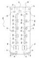
次に、配線基板38a〜38dに実装されている部品を図7を参照して説明する。図7は、配線基板を図6の幅方向x右側から視た構成図である。ここでは、配線基板38aを例示して説明する。図7に示すように、配線基板38a上には、主として、スイッチ18a,19aと、電源監視部48と、スイッチ50,51と、レセプタクル52a,52b,52c,52d,52e,52f,52g,52hと、発光ダイオード53a,53b,53c,53d,53e,53f,53g,53hとが設けられている。 Next, components mounted on the
スイッチ18aは、接続ポート42とディスクアレイ17a(図3参照)の各ドライブ間の信号を切り換えると共に、各ドライブの状態を監視して各ドライブから入力する信号を接続ポート42に出力するものである。また、スイッチ18aは、後記するように、2系統の電源装置5a,5b(図1参照)を切り換える。なお、電源装置5aは、コネクタ8bを経由して配線基板38aに電力を供給し、電源装置5bは、コネクタ8aを経由して配線基板38aに電力を供給する。
スイッチ19aは、接続ポート43の入出力信号を管理する。その他の機能は、スイッチ18aと同様なので説明を省略する。The
The
電源監視部(切替制御手段)48は、後記するように、2系統の電源装置5a,5bを監視して、スイッチ50と、スイッチ51とを制御することにより、ドライブに正常に電力を供給するためのものである。
スイッチ50,51は、コネクタ8aに接続された電源装置5b(図1参照)から供給される電力と、コネクタ8bに接続された電源装置5a(図1参照)から供給される電力とを切り換えるものである。As will be described later, the power supply monitoring unit (switching control unit) 48 monitors the two
The
レセプタクル52a〜52hは、ディスクアレイ17aに属する各ドライブを装着し、各ドライブに信号を入出力すると共に、電力を供給するためのものである。レセプタクル52a〜52hの下方両側には、それぞれ、後記するドライブレールを嵌入するための2つの溝が穿設されている。例えばレセプタクル52gの下方には、溝56a,56bが設けられている。
発光ダイオード53a〜53hは、レセプタクル52a〜52hに電気的に接続され、レセプタクル52a〜52hに装着された各ドライブの動作状態を表示するものである。The
The
配線基板38aの奥行き方向y前方側(図7中左側)の端縁部には、コネクタ54,55が設けられている。このコネクタ54,55には、後記するように、前面パネル40に設けられる発光ダイオードが接続される。
また、配線基板38aの周縁部には、4隅と上下底部を合わせて6箇所に穴57が設けられている。これらの穴57は、配線基板38aをドロワ6a内の後記するドロワフレームに取り付けるためのものである。
Moreover, the
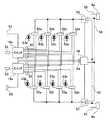
次に、配線基板38a上の部品の配線を図8を参照して説明する。図8は、配線基板の回路図である。なお、図8に示した配線図では、電源配線は、正電源側の接続関係のみ示され、負電源側の配線は省略されている。また、チャネルは、物理的に複数本の配線で構成されていても、一本の線で代表して示されている。
配線基板38a上には、主として、電源線58,59と、電源線60,61と、信号線62,63,64とが配線されている。Next, wiring of components on the
On the
電源線58,59は、コネクタ8aに接続されており、電源線60,61は、コネクタ8bに接続されている。
電源線58,60は、スイッチ50,51を介して、コネクタ8a,8bと、レセプタクル52a〜52hとを接続し、レセプタクル52a〜52hにドライブ用の電力を供給するものである。
電源線59,61は、ドライブ以外の部品、例えばファン39a(図6参照)やスイッチ18a,19a等のための電力を供給するものである。なお、電源線59,61の配線は中途省略されている。The
The
The
また、電源線58,60は、コネクタ8a,8bと、電源監視部48とを接続しているので、電源監視部48は、電源線58から供給される電源電圧と、電源線60から供給される電源電圧とを監視して、スイッチ50とスイッチ51とを制御する。これにより、コネクタ8aとコネクタ8bのどちらか一方に接続された電源装置5a(5b)(図1参照)に障害が発生したとしても、各ドライブに正常な電源装置5a(5b)が接続されることとなる。なお、図8の回路図では、電源正常時において、レセプタクル52a〜52dへの給電は電源装置5bからコネクタ8aを介して行われ、レセプタクル52e〜52hへの給電は電源装置5aからコネクタ8bを介して行われている。電源装置5a,5bのどちらか一方に障害が発生した場合に、レセプタクル52a〜52hへの給電は、正常な他方の電源装置から行われる。 Further, since the
信号線62は、スイッチ18aとレセプタクル52a〜52dとを接続している。また、信号線63は、スイッチ19aとレセプタクル52e〜52hとを接続している。なお、スイッチ18a,19aには、コネクタ54,55と、接続ポート42,43とがそれぞれ接続されている。これにより、発光ダイオード53a〜53hが表示する情報(各ドライブの状態を示す信号)は、スイッチ18a,19aに供給され、さらに、スイッチ18a,19aに接続されたコネクタ54,55に供給される。したがって、このコネクタ54,55に装着された発光ダイオードは、発光ダイオード53a〜53hと同じ情報を表示することができる。 The
信号線64は、スイッチ18a,19aと電源監視部48とを接続している。これにより、電源監視部48は、ディスクコントローラ3からの命令を、接続ポート42、43と、スイッチ18a,19aと、信号線64とを介して受信することができる。したがって、電源監視部48は、ディスクコントローラ3からの命令に基づいて、スイッチ50とスイッチ51とを制御して、電源を切り換えるようにしてもよい。 The
次に、ディスクアレイユニット4を構成するドロワ6a〜6dの構造を図9を参照して説明する。図9は、ディスクアレイユニットを構成するドロワの外観図である。ここでは、ドロワ6aを例示して説明する。
ドロワ6aは、筐体2から引き出されたときに、ラック床板69に配設されたラックレール70,71上を滑走し、所定位置で停止するように構成されている。このようにドロワ6aが引き出されたときの振動を防止するために、ドロワ6aの下部には、底板200上に防振用ゴム72が設けられている。Next, the structure of the
The
ドロワ6aの前面パネル40には、図9に示したように、発光ダイオードアレイ73,74が配設されている。発光ダイオードアレイ73は、水平方向一直線上に配置された4つの発光ダイオードから構成され、配線基板38a(図7参照)上の発光ダイオード53a〜53dと同じ情報を表示する。同様に、発光ダイオードアレイ74は、4つの発光ダイオードから構成され、配線基板38a(図7参照)上の発光ダイオード53e〜53hと同じ情報を表示する。 As shown in FIG. 9, light emitting
ドロワ6aは、骨組みであるドロワフレーム65と、このドロワフレーム65にそれぞれ固定された側面板66および天板67,68とを備えている。
側面板(ガイド部材)66は、ディスクアレイ17a(図6参照)を介して配線基板38a(図6参照)の基板面と対向する面(図9中右側)に固定されている。
天板(ガイド部材)67,68は、配線基板38a(図6参照)の基板面と隣接する面(図9中上側)に固定されている。
これらの側面板66および天板67,68は、ファン39a(図6参照)からの空気の風向きをディスクアレイ17a(図6参照)に向けるためのものである。The
The side plate (guide member) 66 is fixed to a surface (right side in FIG. 9) facing the substrate surface of the
The top plates (guide members) 67 and 68 are fixed to a surface (upper side in FIG. 9) adjacent to the substrate surface of the
The
側面板66には、ドライブ窓75a,75b,75c,75d,75e,75f,75g,75hと、発光ダイオード窓76a,76b,76c,76d,76e,76f,76g,76hとが穿設されている。
ドライブ窓75a〜75hは、ディスクアレイ17a(図6参照)に属する8台のドライブに対応した位置に設けられている。後記するように、8台のドライブは、ドライブ窓75a〜75hから挿入されて、配線基板38a上のレセプタクル52a〜52h(図7参照)に装着される。The
The
発光ダイオード窓76a〜76hは、配線基板38a(図7参照)上の8個の発光ダイオード53a〜53hに対応した位置に設けられている。この発光ダイオード窓76a〜76hには、視認性を向上させるためにレンズ等が設けられている。なお、配線基板38a(図7参照)上の発光ダイオード53a〜53hと、側面板66上の発光ダイオード窓76a〜76hとの間は、ディスクアレイ17a(図6参照)の幅だけ離れている。しかしながら、後記するように、光ファイバを利用することにより、発光ダイオード53a〜53h(図7参照)の光は、発光ダイオード窓76a〜76hを十分に透過することができる。 The light emitting
次に、ドロワ6aへドライブを取り付けるための構成を図10を参照して説明する。図10は、ドライブの取付方法の説明図である。図10に示したドライブレール77a,77bは、一方の端部(図10中左側)が、配線基板38a(図7参照)上のレセプタクル52a〜52hの下方両側に設けられた溝(例えば56a,56b)に嵌入されると共に、他方の端部(図10中右側)が、側面板66上のドライブ窓75a〜75h(図9参照)に渡された状態で、ドロワフレーム65(図9参照)にそれぞれ固定される。これにより、ドライブ78を、例えばドライブ窓75a(図9参照)から挿入すると、このドライブ78は、ドライブレール77a,77bに導かれて、配線基板38a(図7参照)上のレセプタクル52aに装着される。 Next, a configuration for attaching the drive to the
また、ドライブレール77aの上には、光ファイバ79が敷設されている。この光ファイバ79は、配線基板38a(図7参照)上の発光ダイオード53a〜53hの光を発光ダイオード窓76a〜76h(図9参照)へ伝送するものである。なお、光ファイバ79は、発光ダイオード53a〜53h(図7参照)の光が発光ダイオード窓76a〜76h(図9参照)を透過するのに十分な開口数を有する。 An
次に、本実施形態のディスク装置1において、ディスクアレイユニット4を構成するドロワ6a〜6dを筐体2から引き出すときの作用を図11を参照して説明する。図11は、1つのドロワを引き出した状態のディスクアレイユニットの内部を示す斜視図である。ここでは、一例としてドロワ6cが筐体2から引き出されている。例えば、ディスクアレイ17cに属するドライブに障害が発生したときに、障害の生じたドライブを交換するために、ドロワ6cが引き出される。このドロワ6cが引き出されることにより、ディスクアレイ17cと、配線基板38cと、ファン39cとが一体で引き出されることとなる。 Next, in the
このとき、接続ポート42,43とディスクコントローラ3とを接続するチャネル7e,7f(図1参照)は、それぞれ接続状態を維持している。また、配線基板38c上のコネクタ8a,8b(図8参照)と、電源装置5b,5aとを接続する2つの電源ケーブル(図2参照)は、それぞれ接続状態を維持している。したがって、ディスクアレイ17c、ファン39d等には電力が供給される。そのため、ディスクアレイ17cに属する交換対象ではない(正常な)ドライブは、ファン39dからの風を受けながら所定の動作を継続することができる。なお、この風は、各ドライブ以外に配線基板38c上の電子部品も冷却する。ここで、ドロワ6cには、左側面に配線基板38cが設けられると共に、図11には示されていないが、右側面に側面板66(図9参照)が設けられ、上面に天板67,68(図9参照)が設けられ、底面には、底板200が設けられているので、ファン39cからの風を各ドライブに集中することができる。 At this time, the
また、ドロワ6cは、側面板66(図9参照)上の発光ダイオード窓76a〜76hにより、ディスクアレイ17cに属する各ドライブの動作状態を表示することができる。なお、ディスク装置1は、ドロワ6cを筐体2から引き出す前の状態(図1参照)では、前面パネル40の発光ダイオードアレイ73,74(図9参照)により、ディスクアレイ17cに属する各ドライブの動作状態を表示することができる。 Further, the
また、ドロワ6cは、ディスクアレイ17cに属するディスクの回転面が水平方向に配置され、かつ、配線基板38cの基板面が鉛直方向に配置されているので、配線基板38c上に、各ドライブを接続するレセプタクル52a〜52h(図7参照)を高密度に配設することができる。その結果、ディスク装置1は、ドライブを高密度に実装することができる。さらに、ドロワ6cは、配線基板38cの基板面が筐体2の高さ方向z(垂直)に沿って配設されている。そのため、ドロワ6cを引き出す際に異物をドロワ6c内に落としたときに配線をショートさせる虞を、配線基板の基板面が水平に配設されたときと比べて低減することができる。 In the
また、ディスクアレイユニット4は、異なるドロワに属するドライブを組み合わせてRAIDグループを構成したので、例えばドロワ6cを引き出した際に、チャネル7e,7f(図1参照)や電源ケーブル(図2参照)が万が一断線する等しても、例えばドロワ6aに存在する冗長ドライブを利用することができる。その結果、ディスク装置1の信頼性を向上させることができる。 Further, since the
以上本発明について好適な実施形態について例示したが、本発明は第1の実施形態に限定されず、本発明の趣旨を逸脱しない範囲で適宜変更が可能である。例えば、ディスク装置が2列のドライブ列を一度に引き出すことのできるドロワを備えるようにしてもよい。以下に、この場合の種々のバリエーションを第2ないし第6の実施形態として説明する。 As mentioned above, although preferred embodiment was illustrated about this invention, this invention is not limited to 1st Embodiment, In the range which does not deviate from the meaning of this invention, it can change suitably. For example, the disk device may be provided with a drawer that can pull out two drive rows at a time. Hereinafter, various variations in this case will be described as second to sixth embodiments.
(第2の実施形態)
次に、第2の実施形態に係るディスク装置を図12および図13を参照して説明する。第2の実施形態に係るディスク装置は、ディスクアレイユニットの構成が異なる点を除いて、図1に示したディスク装置1と同一の構成であるので、第1の実施形態と異なる点のみを説明する。図12は、第2の実施形態に係るディスク装置のディスクアレイユニットの内部を示す斜視図であり、図13は、図12に示したディスクアレイユニットから1つのドロワを引き出した状態を示す斜視図である。(Second Embodiment)
Next, a disk device according to a second embodiment will be described with reference to FIGS. The disk device according to the second embodiment has the same configuration as that of the
図12に示すように、ディスクアレイユニット80は、ドロワ81と、ドロワ82とを備えている。ドロワ81は、図6に示したドロワ6aとドロワ6bの機能を合わせて形成され、ドロワ82は、図6に示したドロワ6cとドロワ6dの機能を合わせて形成されている。 As shown in FIG. 12, the
ドロワ81は、配線基板83と、ディスクアレイ84,85と、前面パネル86と、ファン87とを備えている。
配線基板83は、図6に示した配線基板38aと配線基板38bとをそれぞれのドライブ接続面が外側に向くように貼り付けたものに相当する。ただし、一方の配線基板は、図7に示した配線基板38aとyz平面に対して面対称になるように各電子部品が実装されている。なお、このときの2枚の配線基板は所定間隔を空けて配設してもよい。この配線基板83は、ドロワ81の幅方向xの中央に設けられている。The
The
隣接したディスクアレイ84,85は、それぞれ配線基板83の左右に接続されている。ディスクアレイ84,85に属する複数のドライブは、図12に示した例では、奥行き方向yに4台、高さ方向zに4段配設されている。すなわち、ディスクアレイ84,85は、それぞれ奥行き方向yに4台配設されたドライブ列を所定間隔を隔てて高さ方向zに4段有している。そして、ディスクアレイユニット80全体としては、前記したドライブ列を幅方向xに4列有している。なお、ディスクアレイ84は、図6に示したディスクアレイ17aに相当し、ディスクアレイ85は、図6に示したディスクアレイ17bに相当する。
前面パネル86は、図6に示した前面パネル40を筐体2の幅方向xに2個連設して形成されたものに相当する。この前面パネル86には、2組のディスクアレイ84,85をディスクコントローラ3に接続するための接続ポートが設けられている。 The
ファン87は、図6に示したファン39a,39bを連設して形成されたものに相当する。なお、図示はされていないが、このファン87には、2組のディスクアレイ84,85を電源装置5a,5bに接続するためのコネクタが設けられている。 The
ドロワ82は、配線基板88と、ディスクアレイ89,90と、前面パネル91と、ファン92とを備えている。これら配線基板88と、ディスクアレイ89,90と、前面パネル91と、ファン92とは、それぞれ、配線基板83と、ディスクアレイ84、85と、前面パネル86と、ファン87と同一の構成なので説明を省略する。 The
図13に示すように、ドロワ81は筐体2から引き出されている。このドロワ81は、ディスクアレイ84,85が配線基板83の両側に配置されている。したがって、筐体2から1つのドロワ81を引き出しただけで、ディスクアレイ84に属するドライブと、ディスクアレイ85に属するドライブとをそれぞれ交換することができる。例えば、ディスクアレイ84に属するドライブと、ディスクアレイ85に属するドライブとの両方に障害が発生したドライブがある場合、ドロワを筐体2から引き出す動作は一度で済む。 As shown in FIG. 13, the
第2の実施形態によれば、筐体2の幅方向x2列のディスクアレイをまとめて引き出すことができるので、1列のディスクアレイを引き出す場合に比べて、ドロワやドロワフレーム等の体積を低減できる。その結果、第2の実施形態に係るディスク装置は、ドライブの実装密度を向上させることができる。 According to the second embodiment, since the disk array of x2 rows in the width direction of the
(第3の実施形態)
次に、第3の実施形態に係るディスク装置を図14を参照して説明する。第3の実施形態に係るディスク装置は、ディスクアレイユニットに電源装置を備えている点を除いて、第2の実施形態のディスク装置と同一の構成であるので、第2の実施形態のディスクアレイユニットと異なる点のみを説明する。図14は、第3の実施形態に係るディスク装置のディスクアレイユニットの内部を示す斜視図である。(Third embodiment)
Next, a disk device according to a third embodiment will be described with reference to FIG. The disk device according to the third embodiment has the same configuration as that of the disk device according to the second embodiment except that the disk array unit includes a power supply device, and therefore the disk array according to the second embodiment. Only the differences from the unit are described. FIG. 14 is a perspective view showing the inside of the disk array unit of the disk device according to the third embodiment.
ディスクアレイユニット100は、図14に示すように、ドロワ101と、ドロワ102とを備えている。なお、図14においては、ドロワ101が筐体2から引き出された状態を示している。ドロワ101は、図13に示したドロワ81の構成要素に加えて、中間パネル103と、電源装置104,105とを備えている。 As shown in FIG. 14, the
中間パネル103は、例えば前面パネル86と同一の構成であり、配線基板83を介して前面パネル86と対向する位置に配設されている。なお、中間パネル103には、接続ポートが複数設けられており、これらの接続ポートを介して、ファン87および電源装置104,105と配線基板83とが接続されている。 The
電源装置104,105は、筐体2の奥行き方向yで中間パネル103の後方の左右にそれぞれ設けられている。電源装置104,105は、図1に示した電源装置5a,5bに相当するものである。なお、ファン87は、電源装置104,105の奥に配設されており、ディスクアレイ84,85等の他に、電源装置104,105をも冷却する。 The
ドロワ102は、図13に示したドロワ82の構成要素に加えて、中間パネル106と、電源装置107,108とを備えている。なお、中間パネル106と、電源装置107,108とは、それぞれ、中間パネル103と、電源装置104,105と同一の構成なので説明を省略する。 The
第3の実施形態によれば、ディスクアレイユニット100に電源装置104,105,107,108を設けたので、筐体2内でディスクアレイユニット100と別の段に電源装置を設ける必要がない。そのため、筐体2の高さ方向zの体積を低減することができる。その結果、ディスク装置全体の体積を低減してドライブの実装密度を向上することができる。さらに、電源装置冷却用のファンとドライブ冷却用のファンとを共用することにより、部品点数を削減することができる。 According to the third embodiment, since the
(第4の実施形態)
次に、第4の実施形態に係るディスク装置を図15を参照して説明する。第4の実施形態に係るディスク装置は、ディスクアレイユニットの構成が異なる点を除いて、図1に示したディスク装置1と同一の構成であるので、第1の実施形態と異なる点のみを説明する。図15は、第4の実施形態に係るディスク装置のディスクアレイユニットの内部を示す斜視図である。(Fourth embodiment)
Next, a disk device according to a fourth embodiment will be described with reference to FIG. The disk device according to the fourth embodiment has the same configuration as the
図15に示すように、ディスクアレイユニット110は、ドロワ111と、ドロワ112とを備えている。ドロワ111は、図6に示したドロワ6bとドロワ6dの機能を合わせて形成され、ドロワ112は、図6に示したドロワ6aとドロワ6cの機能を合わせて形成されている。そして、ディスクアレイユニット110は、ドロワ111が筐体2から前方に引き出されるように構成されていると共に、ドロワ112が筐体2から後方に引き出されるように構成されている。ただし、図6に示したディスクアレイ17aに相当するディスクアレイ113は、ドロワ112に属し、図6に示したディスクアレイ17bに相当するディスクアレイ114は、ドロワ111に属している。また、図6に示したディスクアレイ17cに相当するディスクアレイ115は、ドロワ112に属し、図6に示したディスクアレイ17dに相当するディスクアレイ116は、ドロワ111に属している。 As shown in FIG. 15, the
ドロワ111,112は、それぞれ前面パネル117,118を備えている。前面パネル117は、筐体2の幅方向xに、図6に示したディスクアレイユニット4の前面パネル40とファン39aとが図15中左から交互に2つずつ形成されたものに相当する。同様に、前面パネル118は、筐体2の幅方向xに、図6に示したディスクアレイユニット4のファン39aと前面パネル40とが図15中左から交互に2つずつ形成されたものに相当する。したがって、前面パネル117,118は、ドロワ111,112が筐体2に収納されている状態では、一方が他方の背面パネルの役割をしている。 The
ディスクアレイ113,115は、前面パネル118に所定間隔を隔てて配設された2つの配線基板119,120の外側にそれぞれ接続されている。また、ディスクアレイ114,116は、前面パネル117に所定間隔を隔てて配設された2つの配線基板121,122の外側にそれぞれ接続されている。なお、配線基板119,120と配線基板121,122は、それぞれドライブ接続面が逆方向に臨むように配設される。また、前記した所定間隔は例えば同じ長さであり、ディスクアレイ114の幅と配線基板121の厚さとを合わせた長さ以上の長さ、あるいは、ディスクアレイ115の幅と配線基板120の厚さとを合わせた長さ以上の長さである。 The
また、ディスクアレイユニット110は、例えばドロワ111だけが筐体2から引き出された状態では、前面パネル118が引き出されないので、電源用コネクタ123が前面パネル117(配線基板121,122)に配設されている。なお、図示しない電源用コネクタが前面パネル118(配線基板119,120)にも配設されている。 In the
このような構成のディスクアレイユニット110は、ドロワ111,112が筐体2に収納されている状態では、図6に示したディスクアレイユニット4のドロワ6b,6dの前後を換えて配置したものに相当する。なお、ドライブ冷却風の向きはドロワ毎に変更可能であり、ディスク装置を設置する場所の空調環境を考慮して風向を設定する。 In the state where the
第4の実施形態によれば、ディスクアレイユニット110は、ドロワ111,112を互い違いに奥行き方向yを逆方向に引き出して、それぞれのディスクアレイ113〜116に属するドライブを交換することができる。また、ドロワ111,112は、筐体2の幅方向xに所定間隔離れた2つのディスクアレイを組み合わせて構成したので、ラック床板69(図9参照)に対するドロワ111,112の支持面積が増加することになり、ドロワ111,112を引き出す際の振動を低減することができる。 According to the fourth embodiment, the
(第5の実施形態)
次に、第5の実施形態に係るディスク装置を図16ないし図18を参照して説明する。第5の実施形態に係るディスク装置は、ディスクアレイに属するドライブの配置が異なる点を除いて、第2の実施形態のディスク装置と同様の構成である。図16は、第5の実施形態に係るディスク装置のディスクアレイユニットの断面図であり、図17は、その斜視図である。(Fifth embodiment)
Next, a disk device according to a fifth embodiment will be described with reference to FIGS. The disk device according to the fifth embodiment has the same configuration as the disk device of the second embodiment except that the arrangement of the drives belonging to the disk array is different. FIG. 16 is a cross-sectional view of a disk array unit of a disk device according to the fifth embodiment, and FIG. 17 is a perspective view thereof.
ディスクアレイユニット140は、図16に示すように、専用ラック141と、ドロワ142,143とを備えている。
専用ラック(筐体)141は、例えば、高さ1U(ユニット:44.45mm)の19型ラックである。なお、19型ラックの幅(内寸)は482.6mmである。
ドロワ142は、配線基板144と、この配線基板144に接続されたディスクアレイとして12台(図17参照)のドライブ150とを有している。
また、ドロワ143は、配線基板145と、この配線基板145に接続されたディスクアレイとして12台(図17参照)のドライブ150とを有している。As illustrated in FIG. 16, the
The dedicated rack (housing) 141 is, for example, a 19-inch rack having a height of 1 U (unit: 44.45 mm). The width (inner dimension) of the 19-inch rack is 482.6 mm.
The
The
配線基板144,145はドライブ接続面が両面に形成されている。
ドライブ150は、例えば、2.5型のドライブである。2.5型ドライブは、図18に示すように、長手方向が100mm、レセプタクル接続面がある辺の長さが70mm、厚さが約10mmの大きさを有している。The
The
ドロワ142は、図17に示すように、配線基板144の左側に、4台のドライブ150からなるドライブ列151a,151bを有し、配線基板144の右側に、ドライブ列151cを有している。ドライブ列151bは、ドライブ列151aの下方に位置しており、ドライブ列151cは、ドライブ列151aと同じ高さに位置している。 As shown in FIG. 17, the
同様に、ドロワ143は、配線基板145の左側に、ドライブ列151dを有し、配線基板145の右側に、ドライブ列151e,151fを有している。ドライブ列151d,151fは、ドライブ列151bと同じ高さに位置しており、ドライブ列151eは、ドライブ列151aと同じ高さに位置している。 Similarly, the
ドロワ143に属するドライブ列151dは、その一部が、ドロワ142に属するドライブ列151cの下方に位置している。そのため、ドライブ列151c,151dを合わせて1列2段のドライブ列とみなした場合、ディスクアレイユニット140は、全体として3列2段のドライブ列を有していることになる。あるいは、ドライブ列151c,151dを合わせて2列のドライブ列とみなした場合、ディスクアレイユニット140は、全体として4列のドライブ列を有していることになる。したがって、第5の実施形態によれば、19型ラックの幅方向にドライブ列を3列または4列実装することが可能である。また、図16示すように、専用ラック141の両端には、スペースができるので、このスペースに電源ケーブルの余長分等を格納することができる。 A part of the
(第6の実施形態)
次に、第6の実施形態に係るディスク装置を図19および図20を参照して説明する。第6の実施形態に係るディスク装置は、ディスクアレイに属するドライブの配置が異なる点を除いて、第5の実施形態のディスク装置と同様の構成である。図19は、第6の実施形態に係るディスク装置のディスクアレイユニットの断面図であり、図20は、その斜視図である。(Sixth embodiment)
Next, a disk device according to a sixth embodiment will be described with reference to FIGS. The disk device according to the sixth embodiment has the same configuration as the disk device of the fifth embodiment, except that the arrangement of the drives belonging to the disk array is different. FIG. 19 is a cross-sectional view of a disk array unit of the disk device according to the sixth embodiment, and FIG. 20 is a perspective view thereof.
ディスクアレイユニット160は、図19に示すように、専用ラック161と、ドロワ162,163とを備えている。
専用ラック(筐体)161は、例えば、高さ1U(ユニット:44.45mm)の19型ラックである。
ドロワ162は、配線基板164と、この配線基板164に接続されたディスクアレイとして16台(図20参照)のドライブ150とを有している。
また、ドロワ163は、配線基板165と、この配線基板165に接続されたディスクアレイとして16台(図20参照)のドライブ150とを有している。The
The dedicated rack (housing) 161 is, for example, a 19-inch rack having a height of 1 U (unit: 44.45 mm).
The
The
配線基板164はドライブ接続面が両面に形成されており、ドライブ装着用のレセプタクルの位置がドライブ接続面毎に異なる。例えば、図19に示すように、配線基板164の左側の下段のレセプタクル166の位置は、配線基板164の右側の下段のレセプタクル167の位置よりも数mm高くなっている。また、上段のレセプタクルについても同様である。また、配線基板165は、配線基板164と同様に構成されている。
ドライブ150は、例えば、2.5型のドライブである。The
The
ドロワ162は、図20に示すように、配線基板164の左側に、4台のドライブ150からなるドライブ列152a,152bを有し、配線基板164の右側に、ドライブ列152c,152dを有している。同様に、ドロワ163は、配線基板165の左側に、ドライブ列152e,152fを有し、配線基板165の右側に、ドライブ列152g,152hを有している。 As shown in FIG. 20, the
第6の実施形態によれば、図19に示すように、専用ラック161の両端部をそれぞれ10mm、ドロワ162とドロワ163との間隔とを12.6mm、レセプタクルの幅を含む配線基板164,165の幅を25mmとして、ドライブ150を実装した場合、専用ラック(19型ラック)161の幅方向に、2.5型ドライブのドライブ列を4列並べることができる。なお、ドライブ列毎にドロワを構成する場合(ドロワを4つとする場合)には、ドロワ間の隙間と、配線基板の厚さがさらに増加するので、19型ラックに4列を実装することは難しい。 According to the sixth embodiment, as shown in FIG. 19,
また、第6の実施形態によれば、配線基板164の両側でレセプタクル166,167の位置をずらしたので、配線基板164を介して両側にある2つのレセプタクル166,167のピンが互いに干渉することがない。したがって、配線基板164は、ピンの長さに対応した厚さを必要とすることがないので、その厚さを薄くすることができる。 Further, according to the sixth embodiment, since the positions of the
1 ディスク装置
2 筐体
3 ディスクコントローラ
4 ディスクアレイユニット
5a,5b 電源装置
6a〜6d ドロワ(引出部)
17a〜17d ディスクアレイ
18a〜18d,19a〜19d スイッチ
38a〜38d 配線基板
39a〜39d ファン(送風手段)
40 前面パネル
48 電源監視部(切替制御手段)
65 ドロワフレーム
66 ドロワ側面板
67,68 ドロワ天板
80 ディスクアレイユニット
81,82 ドロワ
83,88 配線基板
84,85 ディスクアレイ
86,91 前面パネル
87,92 ファン(送風手段)
89,90 ディスクアレイ
100 ディスクアレイユニット
101,102 ドロワ
103,106 中間パネル
104,105,107,108 電源装置
110 ディスクアレイユニット
111,112 ドロワ
117,118 前面パネル
119,120,121,122 配線基板
140,160 ディスクアレイユニット
141,161 19型ラック(筐体)
142,143,162,163 ドロワ
150 2.5型ディスクドライブ
151a〜151f,152a〜152h ドライブ列
166,167 レセプタクル(コネクタ)
200 底板DESCRIPTION OF
17a to
40
65
89, 90
142, 143, 162, 163
200 Bottom plate
Claims (13)
Translated fromJapanese前記各ディスクドライブは、
ディスク回転面が前記配線基板の基板面に対して垂直となるように前記配線基板に所定間隔を隔てて接続され、
前記ディスク装置は、
前記複数のディスクドライブ、前記配線基板、および前記送風手段を一体にして前記筐体から引き出す引出部と、
前記引出部が前記筐体に収納されている状態で視認可能な前記引出部の前面パネルに設けられ、前記各ディスクドライブの動作状況を表示する前面表示部と、
前記引出部が前記筐体から引き出された状態で視認可能な前記引出部の側面板に設けられ、前記各ディスクドライブの動作状況を表示する側面表示部と、
を備えることを特徴とするディスク装置。In a disk device having a housing, a plurality of disk drives arranged in the depth direction and the height direction of the housing, a wiring board of each disk drive, and a blowing unit of each disk drive,
Each of the diskdrive,
The disk rotation surface is connected to the wiring board at a predetermined interval so as to be perpendicular to the board surface of the wiring board,
The disk device is
Wherein the plurality of diskdrives,and theprevious SL wiringboard, and the lead-out portion to drawthe blowing handstage from the housing so as to beintegrated,
A front display unit that is provided on a front panel of the drawer unit that is visible in a state where the drawer unit is housed in the housing, and displays an operation status of each disk drive;
A side display unit that is provided on a side plate of the drawer unit that is visible in a state in which the drawer unit is pulled out from the housing, and displays an operation status of each disk drive;
A disk device comprising:
前記各ドライブ列は、前記筐体の高さ方向および幅方向に所定間隔を隔てて配設され、
前記配線基板は、前記筐体の幅方向に配設された隣接する2つのドライブ列の間に、前記配線基板の基板面がディスク回転面に対して垂直となるように配設されると共に、前記配線基板の両面それぞれにディスクドライブ接続面を有し、
前記ディスク装置は、
前記配線基板およびこの配線基板の両側に配設された少なくとも2つのドライブ列を一体にして前記筐体から引き出す引出部と、
前記引出部が前記筐体に収納されている状態で視認可能な前記引出部の前面パネルに設けられ、前記各ディスクドライブの動作状況を表示する前面表示部と、
前記引出部が前記筐体から引き出された状態で視認可能な前記引出部の側面板に設けられ、前記各ディスクドライブの動作状況を表示する側面表示部と、
を備えることを特徴とするディスク装置。In a disk device having a housing, a plurality of drive rows formed by arranging a plurality of disk drives in the depth direction of the housing, and a wiring board of the drive rows,
Each drive train is disposed at a predetermined interval in the height direction and the width direction of the housing,
The wiring board is arranged between two adjacent drive rows arranged in the width direction of the housing so that the board surface of the wiring board is perpendicular to the disk rotation surface, Each side of the wiring board has a disk drive connection surface,
The disk device is
A lead-out portionthat pulls out the wiring boardand at least two driverows disposed on both sides of the wiring board from the housing;
A front display unit that is provided on a front panel of the drawer unit that is visible in a state where the drawer unit is housed in the housing, and displays an operation status of each disk drive;
A side display unit that is provided on a side plate of the drawer unit that is visible in a state in which the drawer unit is pulled out from the housing, and displays an operation status of each disk drive;
Diskapparatus characterized byobtaining Bei a.
前記各ドライブ列は、前記筐体の高さ方向および幅方向に所定間隔を隔てて配設され、
前記配線基板は、前記筐体の幅方向に配設された隣接する2つのドライブ列の間に、前記配線基板の基板面がディスク回転面に対して垂直となるように配設されると共に、前記配線基板の両面それぞれにディスクドライブ接続面を有し、
前記ディスク装置は、
前記配線基板、この配線基板の両側に配設された少なくとも2つのドライブ列、および前記送風手段を一体にして前記筐体から引き出す引出部と、
前記引出部が前記筐体に収納されている状態で視認可能な前記引出部の前面パネルに設けられ、前記各ディスクドライブの動作状況を表示する前面表示部と、
前記引出部が前記筐体から引き出された状態で視認可能な前記引出部の側面板に設けられ、前記各ディスクドライブの動作状況を表示する側面表示部と、
を備えることを特徴とするディスク装置。In a disk device having a housing, a plurality of drive rows formed by arranging a plurality of disk drives in the depth direction of the housing, a wiring board of the drive rows, and a blowing means of each disk drive,
Each drive train is disposed at a predetermined interval in the height direction and the width direction of the housing,
The wiring board is arranged between two adjacent drive rows arranged in the width direction of the housing so that the board surface of the wiring board is perpendicular to the disk rotation surface, Each side of the wiring board has a disk drive connection surface,
The disk device is
The wiringboard,and a lead-out portion to draw at least two columns of drives arranged on both sides of the wiringboard, andthe blowing handstage from the housing so as to beintegrated,
A front display unit that is provided on a front panel of the drawer unit that is visible in a state where the drawer unit is housed in the housing, and displays an operation status of each disk drive;
A side display unit that is provided on a side plate of the drawer unit that is visible in a state in which the drawer unit is pulled out from the housing, and displays an operation status of each disk drive;
Diskapparatus characterized byobtaining Bei a.
前記筐体は、19型ラックからなり、
前記各ドライブ列を、前記筐体内の幅方向に3列または4列並べて配設したことを特徴とする請求項4または請求項5に記載のディスク装置。The disk drives belonging to each drive row are 2.5 type drives,
The housing consists of a 19-inch rack,
6. The disk device according to claim 4, wherein the drive rows are arranged in three or four rows in the width direction in the housing.
前記各ドライブ列は、前記筐体の高さ方向および幅方向に所定間隔を隔てて配設されると共に、ディスク回転面が前記配線基板に対して垂直となるようにして前記配線基板に接続され、
前記配線基板は、ディスクドライブ接続面が互いに逆方向に臨むように前記筐体の幅方向に所定間隔を隔てて2枚配設され、
前記配線基板と、この配線基板に接続された少なくとも2つのドライブ列と、前記送風手段とを一体にして前記筐体から引き出す引出部を複数備え、
前記2枚の配線基板を隔てる所定間隔は、前記各ドライブ列の前記筐体の幅方向の長さと、前記配線基板の厚さとを合計した長さよりも長く、
異なる前記引出部が互い違いに前記筐体の奥行き方向を逆方向に引き出し可能に構成され、
前記ディスク装置は、
前記引出部が前記筐体に収納されている状態で視認可能な前記引出部の前面パネルに設けられ、前記各ディスクドライブの動作状況を表示する前面表示部と、
前記引出部が前記筐体から引き出された状態で視認可能な前記引出部の側面板に設けられ、前記各ディスクドライブの動作状況を表示する側面表示部と、
を備えることを特徴とするディスク装置。In a disk device having a housing, a plurality of drive rows formed by arranging a plurality of disk drives in the depth direction of the housing, a wiring board of the drive rows, and a blowing means of each disk drive,
Each drive train is disposed at a predetermined interval in the height direction and the width direction of the housing, and is connected to the wiring board such that a disk rotation surface is perpendicular to the wiring board. ,
Two of the wiring boards are arranged at a predetermined interval in the width direction of the housing so that the disk drive connection surfaces face in opposite directions to each other,
The wiring board, at least two drive rows connected to the wiring board, and a plurality of pull-out portions that pull out from the housing integrally with the blowing means,
The predetermined interval separating the two wiring boards is longer than the total length of the lengths of the housings in the width direction of the drive columns and the thickness of the wiring boards.
The different drawers are configured to be capable of alternately pulling out the depth direction of the housing in the opposite direction,
The disk device is
A front display unit that is provided on a front panel of the drawer unit that is visible in a state where the drawer unit is housed in the housing, and displays an operation status of each disk drive;
A side display unit that is provided on a side plate of the drawer unit that is visible in a state in which the drawer unit is pulled out from the housing, and displays an operation status of each disk drive;
Disk apparatuscomprising: a.
前記各引出部内の前記各ディスクドライブは、前記配線基板の両基板面にそれぞれ、前記筐体の奥行き方向に所定間隔を隔てて複数台配置するとともに、高さ方向に所定間隔を隔てて複数段配置し、
前記配線基板の各基板面をディスク回転面に対して垂直となるように配設し、
前記各引出部内の前記ディスクドライブを組み合わせてデータ冗長用論理グループを構成し、
前記各引出部を前記筐体から前記奥行き方向に沿って引き出し可能に構成し、
前記ディスク装置は、
前記引出部が前記筐体に収納されている状態で視認可能な前記引出部の前面パネルに設けられ、前記各ディスクドライブの動作状況を表示する前面表示部と、
前記引出部が前記筐体から引き出された状態で視認可能な前記引出部の側面板に設けられ、前記各ディスクドライブの動作状況を表示する側面表示部と、
を備えることを特徴とするディスク装置。A plurality of disk drives, a wiring board capable of controlling the operation of each disk drive, and two drawer parts integrally equipped with the air blowing means of each disk drive, and a housing for housing these drawer parts A disk device with a body,
Each of the disk drives in each of the lead-out portions is arranged on a plurality of board surfaces of the wiring board at a predetermined interval in the depth direction of the housing, and a plurality of stages are provided at a predetermined interval in the height direction. Place and
Each substrate surface of the wiring substrate is arranged to be perpendicular to the disk rotation surface,
Combining the disk drives in each of the drawers to form a data redundancy logical group,
Each drawer part is configured to be drawable from the casing along the depth direction,
The disk device is
A front display unit that is provided on a front panel of the drawer unit that is visible in a state where the drawer unit is housed in the housing, and displays an operation status of each disk drive;
A side display unit that is provided on a side plate of the drawer unit that is visible in a state in which the drawer unit is pulled out from the housing, and displays an operation status of each disk drive;
Disk apparatuscomprising: a.
前記前面パネルに設けられ、前記各ディスクドライブと一対一に対応する発光ダイオードを有し、 A light emitting diode provided on the front panel and corresponding to each of the disk drives;
前記側面表示部は、 The side display unit is
前記配線基板に設けられ、前記各ディスクドライブと一対一に対応する発光ダイオードと、 Light emitting diodes provided on the wiring board and corresponding one-to-one with the disk drives,
前記側面板に穿設された発光ダイオード窓と、 A light emitting diode window drilled in the side plate;
前記発光ダイオードで発生した光を前記発光ダイオード窓へと導光する光ファイバとを有するAn optical fiber for guiding the light generated by the light emitting diode to the light emitting diode window;
ことを特徴とする請求項1乃至請求項12のいずれか1項に記載のディスク装置。The disk device according to claim 1, wherein the disk device is a disk device.
Priority Applications (3)
| Application Number | Priority Date | Filing Date | Title |
|---|---|---|---|
| JP2005045365AJP4621039B2 (en) | 2005-02-22 | 2005-02-22 | Disk unit |
| US11/119,848US7349204B2 (en) | 2005-02-22 | 2005-05-03 | Disk device |
| CN200510132342XACN1825464B (en) | 2005-02-22 | 2005-12-21 | Disk device |
Applications Claiming Priority (1)
| Application Number | Priority Date | Filing Date | Title |
|---|---|---|---|
| JP2005045365AJP4621039B2 (en) | 2005-02-22 | 2005-02-22 | Disk unit |
Publications (2)
| Publication Number | Publication Date |
|---|---|
| JP2006235696A JP2006235696A (en) | 2006-09-07 |
| JP4621039B2true JP4621039B2 (en) | 2011-01-26 |
Family
ID=36912453
Family Applications (1)
| Application Number | Title | Priority Date | Filing Date |
|---|---|---|---|
| JP2005045365AExpired - Fee RelatedJP4621039B2 (en) | 2005-02-22 | 2005-02-22 | Disk unit |
Country Status (3)
| Country | Link |
|---|---|
| US (1) | US7349204B2 (en) |
| JP (1) | JP4621039B2 (en) |
| CN (1) | CN1825464B (en) |
Families Citing this family (51)
| Publication number | Priority date | Publication date | Assignee | Title |
|---|---|---|---|---|
| JP2006164006A (en)* | 2004-12-09 | 2006-06-22 | Hitachi Ltd | Disk array device |
| US8385061B2 (en)* | 2006-10-24 | 2013-02-26 | Lsi Corporation | System and method for implementing a meta-disk aggregation model for storage controllers |
| JP2008152662A (en)* | 2006-12-19 | 2008-07-03 | Kwok-Yan Leung | System and method for performing quick retrieval from large numbers of hard disk groups |
| US7650447B2 (en)* | 2007-02-16 | 2010-01-19 | Apple Inc. | System and method for a host to access an internal SATA storage device within an accessible host using an external serial ATA connection |
| JP4821679B2 (en)* | 2007-03-30 | 2011-11-24 | 富士通株式会社 | Magnetic disk module and aggregate disk device |
| US7881062B2 (en)* | 2007-07-09 | 2011-02-01 | Mitac International Corp. | Extension bracket module |
| US7348743B1 (en)* | 2007-10-30 | 2008-03-25 | International Business Machines Corporation | Apparatus to remove foreign particles from heat transfer surfaces of heat sinks |
| JP2010125727A (en) | 2008-11-28 | 2010-06-10 | Seiko Epson Corp | Liquid ejecting head, method of manufacturing the same, and liquid ejecting device |
| GB2467404B (en)* | 2008-12-23 | 2011-12-14 | Nexsan Technologies Ltd | Electronic apparatus |
| GB0823407D0 (en)* | 2008-12-23 | 2009-01-28 | Nexan Technologies Ltd | Apparatus for storing data |
| KR20120027472A (en)* | 2009-06-05 | 2012-03-21 | 지라텍스 테크놀로지 리미티드 | Apparatus for supporting a disk drive and disk drive test apparatus |
| US8364927B2 (en) | 2009-11-12 | 2013-01-29 | Hitachi, Ltd. | Disk array system and hard disk drive expansion method thereof |
| CN102129273A (en)* | 2010-01-16 | 2011-07-20 | 鸿富锦精密工业(深圳)有限公司 | Computer system |
| KR101297158B1 (en) | 2010-02-22 | 2013-08-21 | 제일모직주식회사 | Compound for organic photoelectric device and organic photoelectric device including the same |
| US8743549B2 (en) | 2011-03-22 | 2014-06-03 | Amazon Technologies, Inc. | Modular mass storage system |
| US9251097B1 (en) | 2011-03-22 | 2016-02-02 | Amazon Technologies, Inc. | Redundant key management |
| US8644017B2 (en) | 2011-05-26 | 2014-02-04 | Lsi Corporation | Storage device carriers for adapting a storage device of a first size to a slot for a storage device of a second size |
| US9019708B2 (en)* | 2011-08-25 | 2015-04-28 | Lsi Corporation | Apparatus and systems having storage devices in a side accessible drive sled |
| US8553357B1 (en) | 2012-03-26 | 2013-10-08 | Amazon Technologies, Inc. | Cooling of hard disk drives with separate mechanical module and drive control module |
| US8908326B1 (en) | 2012-03-26 | 2014-12-09 | Amazon Technologies, Inc. | Hard disk drive mechanical modules with common controller |
| US8929024B1 (en)* | 2012-03-26 | 2015-01-06 | Amazon Technologies, Inc. | Hard disk drive assembly with field-separable mechanical module and drive control |
| US9904788B2 (en) | 2012-08-08 | 2018-02-27 | Amazon Technologies, Inc. | Redundant key management |
| US9198322B2 (en) | 2013-01-23 | 2015-11-24 | Dot Hill Systems Corporation | Compliant drawer latch assembly |
| US9763350B2 (en)* | 2013-01-23 | 2017-09-12 | Seagate Technology Llc | High density data storage system with improved storage device access |
| US9456515B2 (en) | 2013-01-23 | 2016-09-27 | Seagate Technology Llc | Storage enclosure with independent storage device drawers |
| US9681576B2 (en) | 2013-01-23 | 2017-06-13 | Seagate Technology Llc | Shock dampening drawer slide |
| US9098233B2 (en) | 2013-01-23 | 2015-08-04 | Dot Hill Systems Corporation | Storage device carrier for high density storage system |
| US9274548B2 (en)* | 2013-03-01 | 2016-03-01 | Seagate Technology Llc | Electronic apparatus comprising backplane and methods of assembling and disassembling |
| US10222842B2 (en) | 2013-08-02 | 2019-03-05 | Amazon Technologies, Inc. | System for compute node maintenance with continuous cooling |
| US9141156B2 (en) | 2013-08-02 | 2015-09-22 | Amazon Technologies, Inc. | Compute node cooling with air fed through backplane |
| CN104423457A (en)* | 2013-09-11 | 2015-03-18 | 鸿富锦精密电子(天津)有限公司 | Electronic device and fixing rack thereof |
| US9936611B1 (en) | 2014-03-17 | 2018-04-03 | Amazon Technologies, Inc. | Modular mass storage system |
| US9363926B1 (en) | 2014-03-17 | 2016-06-07 | Amazon Technologies, Inc. | Modular mass storage system with staggered backplanes |
| US10398060B1 (en) | 2014-03-17 | 2019-08-27 | Amazon Technologies, Inc. | Discrete cooling module |
| US9448601B1 (en) | 2014-03-17 | 2016-09-20 | Amazon Technologies, Inc. | Modular mass storage system with controller |
| JP5820500B2 (en)* | 2014-04-25 | 2015-11-24 | 株式会社日立製作所 | Disk array system |
| US9706687B1 (en) | 2014-06-30 | 2017-07-11 | EMC IP Holding Company LLC | Electronic equipment chassis having storage devices and other modules configured for front-access removability |
| CN105549699B (en)* | 2014-10-30 | 2019-03-08 | 英业达科技有限公司 | The connection expansion type computer installation to be radiated using heat dissipation channel |
| US9715795B2 (en)* | 2014-10-30 | 2017-07-25 | International Business Machines Corporation | Indicator module for modular computing units |
| US20160183402A1 (en)* | 2014-12-23 | 2016-06-23 | Intel Corporation | Reducing trace length and insertion loss of high speed signals on a network switch board |
| US9854695B1 (en) | 2015-09-29 | 2017-12-26 | Cisco Technology, Inc. | Single rack unit storage blade with redundant controllers |
| US9968005B2 (en)* | 2016-03-08 | 2018-05-08 | Quanta Computer, Inc. | Different HDD gap architecture to reduce upstream preheat for high-density storage |
| KR102145983B1 (en)* | 2016-12-15 | 2020-08-19 | 주식회사 스토리지안 | Rackmount Case Storage System with Attachable or Detachable Body |
| US10776298B2 (en)* | 2016-12-22 | 2020-09-15 | Seagate Technology, Llc | Multi-device data storage module |
| US10841246B2 (en)* | 2017-08-30 | 2020-11-17 | Arista Networks, Inc. | Distributed core switching with orthogonal fabric card and line cards |
| US10849253B2 (en)* | 2017-09-28 | 2020-11-24 | Hewlett Packard Enterprise Development Lp | Interconnected modular server and cooling means |
| US10531592B1 (en)* | 2018-07-19 | 2020-01-07 | Quanta Computer Inc. | Smart rack architecture for diskless computer system |
| US10986423B2 (en) | 2019-04-11 | 2021-04-20 | Arista Networks, Inc. | Network device with compact chassis |
| US11266007B2 (en) | 2019-09-18 | 2022-03-01 | Arista Networks, Inc. | Linecard system using riser printed circuit boards (PCBS) |
| US11531383B1 (en) | 2020-09-30 | 2022-12-20 | Amazon Technologies, Inc. | Mist cooling for computer systems |
| US12382607B1 (en) | 2023-05-02 | 2025-08-05 | Amazon Technologies, Inc. | Liquid immersion chassis liner |
Family Cites Families (26)
| Publication number | Priority date | Publication date | Assignee | Title |
|---|---|---|---|---|
| JPS5853894A (en)* | 1981-09-25 | 1983-03-30 | 日本電気株式会社 | Electronic package mounting structure |
| JPH0756523Y2 (en)* | 1989-11-21 | 1995-12-25 | アイワ株式会社 | Telephone line holding circuit |
| JPH0719187Y2 (en)* | 1990-05-16 | 1995-05-01 | 富士通株式会社 | Electronic device unit mounting structure |
| US5247427A (en)* | 1992-08-26 | 1993-09-21 | Data General Corporation | Disk array subsystem having elongated T-shaped guides for use in a data processing system |
| FR2704350B1 (en)* | 1993-04-22 | 1995-06-02 | Bull Sa | Physical structure of a mass memory subsystem. |
| JPH0822379A (en)* | 1994-07-08 | 1996-01-23 | Hitachi Ltd | Disk array device |
| JPH08137631A (en)* | 1994-11-15 | 1996-05-31 | Hitachi Ltd | Disk array device |
| US5684671A (en)* | 1995-08-22 | 1997-11-04 | Sequent Computer Systems, Inc. | Packaging architecture for a data server |
| JPH09146711A (en)* | 1995-11-24 | 1997-06-06 | Hitachi Ltd | Collective disk unit |
| JPH09172240A (en)* | 1995-12-20 | 1997-06-30 | Nippon Telegr & Teleph Corp <Ntt> | Three-dimensional mounting structure |
| US5673029A (en)* | 1996-02-15 | 1997-09-30 | Orbitron Computer System, Inc. | Apparatus for cooling a memory storage device |
| JP2845271B2 (en)* | 1996-10-30 | 1999-01-13 | 日本電気株式会社 | Electronic equipment mounting equipment |
| JP3088355B2 (en)* | 1997-09-01 | 2000-09-18 | 日本電気通信システム株式会社 | Through-hole connector structure for double-sided mounting |
| SG106555A1 (en)* | 1998-09-15 | 2004-10-29 | Molex Inc | Circuit board mounted electrical connector |
| JP2002043775A (en)* | 2000-07-21 | 2002-02-08 | Oki Comtec Ltd | Unit for electronic apparatus |
| US6392884B1 (en)* | 2000-08-01 | 2002-05-21 | Shin Jiuh Corp. | Housing assembly for extractable redundant array of independent disks |
| US6510050B1 (en)* | 2000-11-21 | 2003-01-21 | Sun Microsystems, Inc. | High density packaging for multi-disk systems |
| JP3584466B2 (en)* | 2001-05-16 | 2004-11-04 | 日本電気株式会社 | Disk array |
| JP3698360B2 (en)* | 2001-07-13 | 2005-09-21 | インターナショナル・ビジネス・マシーンズ・コーポレーション | Electronic equipment and racks containing electronic equipment |
| US6892275B2 (en)* | 2002-02-05 | 2005-05-10 | Quantum Corporation | Storage system utilizing an active subset of drives during data storage and retrieval operations |
| US6665179B2 (en)* | 2002-02-06 | 2003-12-16 | Shin Jiuh Corp. | Blade server module |
| JP2004153017A (en)* | 2002-10-30 | 2004-05-27 | Nec Corp | Shelf, and electronic component |
| US7200008B1 (en)* | 2004-07-01 | 2007-04-03 | Bhugra Kern S | Multi-depth drive enclosure |
| JP4335760B2 (en)* | 2004-07-08 | 2009-09-30 | 富士通株式会社 | Rack mount storage unit and rack mount disk array device |
| US7362565B2 (en)* | 2004-09-21 | 2008-04-22 | Dot Hill Systems Corporation | Disk drive support system |
| US7298612B2 (en)* | 2005-10-25 | 2007-11-20 | Hewlett-Packard Development Company, L.P. | Server with vertical drive arrangement |
- 2005
- 2005-02-22JPJP2005045365Apatent/JP4621039B2/ennot_activeExpired - Fee Related
- 2005-05-03USUS11/119,848patent/US7349204B2/ennot_activeExpired - Fee Related
- 2005-12-21CNCN200510132342XApatent/CN1825464B/ennot_activeExpired - Fee Related
Also Published As
| Publication number | Publication date |
|---|---|
| CN1825464B (en) | 2012-04-25 |
| US20060187634A1 (en) | 2006-08-24 |
| JP2006235696A (en) | 2006-09-07 |
| CN1825464A (en) | 2006-08-30 |
| US7349204B2 (en) | 2008-03-25 |
Similar Documents
| Publication | Publication Date | Title |
|---|---|---|
| JP4621039B2 (en) | Disk unit | |
| JP4898598B2 (en) | Cooling structure of rack mount type control device and rack type storage control device | |
| US7493444B2 (en) | Substrate structure of disk array apparatus, disk array apparatus and disk array system | |
| JP4693891B2 (en) | Storage controller | |
| EP1975940B1 (en) | Disk array system | |
| JP2006073045A (en) | Storage system | |
| US9934824B2 (en) | Hard disk drive assembly with field-separable mechanical module and drive control | |
| JP2006164006A (en) | Disk array device | |
| WO2000068760A2 (en) | Canister having a combined guide rail and light pipe system for use in a computer peripheral enclosure | |
| US5398158A (en) | Multiple disk drive module with standard from factor | |
| JP2013045440A (en) | Device and system having storage device in lateral face accessible drive thread | |
| JP2006163695A (en) | Storage device, storage device storage unit and dummy unit | |
| JP2005182245A (en) | Connection support method for disk array device | |
| KR101913784B1 (en) | Ssd multipler and the storage system based on it | |
| US9280174B2 (en) | Data storage device enclosure and module | |
| JP5035230B2 (en) | Disk mounting mechanism and storage device | |
| JP2006323574A (en) | Disk array device | |
| KR100992033B1 (en) | Reconfigurable FC-AL Storage Loop in Data Storage System | |
| JP4361033B2 (en) | Disk array device | |
| US8341347B2 (en) | Storage controller | |
| US10261553B2 (en) | Data storage device enclosure | |
| JP2004118946A (en) | Disk array device, storage device unit, disk array device control method, and program | |
| JP2000149524A (en) | Server with independent hdd rack | |
| GB2266615A (en) | Disk drive module | |
| JP4497963B2 (en) | Storage device |
Legal Events
| Date | Code | Title | Description |
|---|---|---|---|
| A621 | Written request for application examination | Free format text:JAPANESE INTERMEDIATE CODE: A621 Effective date:20070530 | |
| A131 | Notification of reasons for refusal | Free format text:JAPANESE INTERMEDIATE CODE: A131 Effective date:20100105 | |
| A521 | Request for written amendment filed | Free format text:JAPANESE INTERMEDIATE CODE: A523 Effective date:20100302 | |
| TRDD | Decision of grant or rejection written | ||
| A01 | Written decision to grant a patent or to grant a registration (utility model) | Free format text:JAPANESE INTERMEDIATE CODE: A01 Effective date:20101026 | |
| A01 | Written decision to grant a patent or to grant a registration (utility model) | Free format text:JAPANESE INTERMEDIATE CODE: A01 | |
| A61 | First payment of annual fees (during grant procedure) | Free format text:JAPANESE INTERMEDIATE CODE: A61 Effective date:20101029 | |
| FPAY | Renewal fee payment (event date is renewal date of database) | Free format text:PAYMENT UNTIL: 20131105 Year of fee payment:3 | |
| R150 | Certificate of patent or registration of utility model | Free format text:JAPANESE INTERMEDIATE CODE: R150 | |
| R250 | Receipt of annual fees | Free format text:JAPANESE INTERMEDIATE CODE: R250 | |
| LAPS | Cancellation because of no payment of annual fees |