JP4620928B2 - Temporary holding drum and method of cutting material on temporary holding drum - Google Patents
Temporary holding drum and method of cutting material on temporary holding drumDownload PDFInfo
- Publication number
- JP4620928B2 JP4620928B2JP2002268183AJP2002268183AJP4620928B2JP 4620928 B2JP4620928 B2JP 4620928B2JP 2002268183 AJP2002268183 AJP 2002268183AJP 2002268183 AJP2002268183 AJP 2002268183AJP 4620928 B2JP4620928 B2JP 4620928B2
- Authority
- JP
- Japan
- Prior art keywords
- drum
- groove
- cylindrical
- temporary holding
- door panel
- Prior art date
- Legal status (The legal status is an assumption and is not a legal conclusion. Google has not performed a legal analysis and makes no representation as to the accuracy of the status listed.)
- Expired - Fee Related
Links
Images


Classifications
- B—PERFORMING OPERATIONS; TRANSPORTING
- B29—WORKING OF PLASTICS; WORKING OF SUBSTANCES IN A PLASTIC STATE IN GENERAL
- B29D—PRODUCING PARTICULAR ARTICLES FROM PLASTICS OR FROM SUBSTANCES IN A PLASTIC STATE
- B29D30/00—Producing pneumatic or solid tyres or parts thereof
- B29D30/06—Pneumatic tyres or parts thereof (e.g. produced by casting, moulding, compression moulding, injection moulding, centrifugal casting)
- B29D30/08—Building tyres
- B29D30/20—Building tyres by the flat-tyre method, i.e. building on cylindrical drums
- B29D30/24—Drums
- B29D30/26—Accessories or details, e.g. membranes, transfer rings
- B—PERFORMING OPERATIONS; TRANSPORTING
- B29—WORKING OF PLASTICS; WORKING OF SUBSTANCES IN A PLASTIC STATE IN GENERAL
- B29D—PRODUCING PARTICULAR ARTICLES FROM PLASTICS OR FROM SUBSTANCES IN A PLASTIC STATE
- B29D30/00—Producing pneumatic or solid tyres or parts thereof
- B29D30/06—Pneumatic tyres or parts thereof (e.g. produced by casting, moulding, compression moulding, injection moulding, centrifugal casting)
- B29D30/38—Textile inserts, e.g. cord or canvas layers, for tyres; Treatment of inserts prior to building the tyre
- B29D30/46—Cutting textile inserts to required shape
- B—PERFORMING OPERATIONS; TRANSPORTING
- B26—HAND CUTTING TOOLS; CUTTING; SEVERING
- B26D—CUTTING; DETAILS COMMON TO MACHINES FOR PERFORATING, PUNCHING, CUTTING-OUT, STAMPING-OUT OR SEVERING
- B26D7/00—Details of apparatus for cutting, cutting-out, stamping-out, punching, perforating, or severing by means other than cutting
- B26D7/20—Cutting beds
- B26D2007/202—Rollers or cylinders being pivoted during operation
- B—PERFORMING OPERATIONS; TRANSPORTING
- B29—WORKING OF PLASTICS; WORKING OF SUBSTANCES IN A PLASTIC STATE IN GENERAL
- B29D—PRODUCING PARTICULAR ARTICLES FROM PLASTICS OR FROM SUBSTANCES IN A PLASTIC STATE
- B29D30/00—Producing pneumatic or solid tyres or parts thereof
- B29D30/06—Pneumatic tyres or parts thereof (e.g. produced by casting, moulding, compression moulding, injection moulding, centrifugal casting)
- B29D30/08—Building tyres
- B29D30/20—Building tyres by the flat-tyre method, i.e. building on cylindrical drums
- B29D30/24—Drums
- B29D2030/241—Auxiliary drums used for temporary storage of the layers before application to the building drums
- Y—GENERAL TAGGING OF NEW TECHNOLOGICAL DEVELOPMENTS; GENERAL TAGGING OF CROSS-SECTIONAL TECHNOLOGIES SPANNING OVER SEVERAL SECTIONS OF THE IPC; TECHNICAL SUBJECTS COVERED BY FORMER USPC CROSS-REFERENCE ART COLLECTIONS [XRACs] AND DIGESTS
- Y10—TECHNICAL SUBJECTS COVERED BY FORMER USPC
- Y10T—TECHNICAL SUBJECTS COVERED BY FORMER US CLASSIFICATION
- Y10T83/00—Cutting
- Y10T83/04—Processes
- Y10T83/0448—With subsequent handling [i.e., of product]
- Y10T83/0472—By moving work support to which a tacky product is adhered
- Y—GENERAL TAGGING OF NEW TECHNOLOGICAL DEVELOPMENTS; GENERAL TAGGING OF CROSS-SECTIONAL TECHNOLOGIES SPANNING OVER SEVERAL SECTIONS OF THE IPC; TECHNICAL SUBJECTS COVERED BY FORMER USPC CROSS-REFERENCE ART COLLECTIONS [XRACs] AND DIGESTS
- Y10—TECHNICAL SUBJECTS COVERED BY FORMER USPC
- Y10T—TECHNICAL SUBJECTS COVERED BY FORMER US CLASSIFICATION
- Y10T83/00—Cutting
- Y10T83/04—Processes
- Y10T83/0605—Cut advances across work surface
- Y—GENERAL TAGGING OF NEW TECHNOLOGICAL DEVELOPMENTS; GENERAL TAGGING OF CROSS-SECTIONAL TECHNOLOGIES SPANNING OVER SEVERAL SECTIONS OF THE IPC; TECHNICAL SUBJECTS COVERED BY FORMER USPC CROSS-REFERENCE ART COLLECTIONS [XRACs] AND DIGESTS
- Y10—TECHNICAL SUBJECTS COVERED BY FORMER USPC
- Y10T—TECHNICAL SUBJECTS COVERED BY FORMER US CLASSIFICATION
- Y10T83/00—Cutting
- Y10T83/606—Interrelated tool actuating means and guard means
- Y10T83/619—Cutter guide slot closer
Landscapes
- Engineering & Computer Science (AREA)
- Mechanical Engineering (AREA)
- Textile Engineering (AREA)
- Life Sciences & Earth Sciences (AREA)
- Forests & Forestry (AREA)
- Tyre Moulding (AREA)
Description
Translated fromJapanese【0001】
【発明の属する技術分野】
本発明は、空気入りタイヤの組立に使われる材料の準備に用いられる方法と装置に関する。本発明は、特に、タイヤ組立材料(例えばエラストマシート)を、タイヤ組立ドラムへの移送に先立って切断されるあいだ保持する「一時保持ドラム(False Drum)」式給送装置に適した一時保持ドラムと、その上の材料を切断する方法に関する。
【0002】
【従来の技術】
例えば自動車などの乗物のタイヤを作る場合に、最初に、いくつかの異なる構成部品を次々に組み込むことによって、いわゆるカーカスを製造することが知られている。言い換えれば、製品群に含まれている、タイプの異なるカーカスは、さまざまな付属構成部品の有無および/または付属構成部品自体の型式に応じて互いに区別され得る。一例として、チューブレスタイヤ、すなわち使用時にインナーチューブが存在する必要のないタイヤのカーカスを製造するときの、主な構成部品は、エラストマの不通気性材料の層であるいわゆるインナーライナと、カーカスプライと、一般にビードコアと呼ばれる1対の環状の金属部材を含むと考えられ、1対の環状の金属部材は、カーカスプライの両端部と、エラストマ材料で作られカーカスプライを越えて両側方位置に延びている1対のサイドウォールとに包み込まれている。付属構成部品は、1つまたは2つ以上の付加的なカーカスプライと、1つまたは複数のカーカスプライの上の、ビードコアを中心として折り返されている領域に覆い被さる1つまたは2つ以上の補強バンド(チェーファ・ストリップ)等が、順番に組み込まれていてもよい。
【0003】
あるタイヤ組立ラインでは、さまざまな種類の給送装置が、タイヤのインナーライナなどの平らな材料を所定のサイズに切断するときに確実に保持することを目的として用いられる。給送装置は、一般に、英国特許第1,010,597号(ダンロップ・ラバー・カンパニー)に示されているもの、または、連続する平らなシート材を平形コンベヤ上で切断刃まで搬送し、それから材料を取り出して、組み立てられるタイヤ上に配置する、米国特許第4,722,255号(チョート他)に示されている運搬および切断システムなどの、平形コンベヤタイプである。材料をコンベヤシステムに給送する「移送ドラム」部材を組み込んだ、さらに別のコンベヤシステムが、米国特許第5,820,726号(ヨシダ他)に教示されている。
【0004】
ドラム式給送装置、すなわち、いわゆる「一時保持ドラム」式給送装置は、材料を測って取り出し、所定の長さに切断し、タイヤに組み込まれるまで材料を保持する間、しっかり保持されていなくてはならない、平らな、すなわちシート状のタイヤ材料のための、別のコンベヤシステムである。シート材は、切断された後に、組立ドラムで組立中のタイヤまで移動される。一般に、そのような一時保持ドラム式給送装置は、円筒の軸線を中心として回転できる、水平に配置されたドラム、すなわち円筒体からなる。ある特定の一時保持ドラム式給送装置は、中空の円筒状のドラムから構成されている。ドラムの表面は、その外周の50〜80パーセント、好ましくは60〜70パーセント、最も好ましくは66パーセントに穴が開けられており、十分な量の空気がドラムからポンプで排出されて、ドラム内を低圧にすることによって、給送装置に保持されながら切断される、平らな、すなわちシート状の材料を確実に保持できる吸着面が設けられる。タイヤのインナーライナなどの平らなシート材が給送装置の穴の開いた円筒部に置かれると、材料が切断処理されている間、ドラムの内側と外側の間の圧力差によって、平らな材料はドラム表面に付着させられる。
【0005】
同様に平らな材料を円筒表面に保持する別のドラム式給送装置が、米国特許第4,504,337号(アスカム他)に教示されており、これには、切断のために保持される平らな材料を磁性面によって確実に保持する方法のドラム式給送装置が記載されている。しかしながら、そのような装置は、当然のことながら、ワイヤ、コード、または金属クロスなどの、鉄鋼すなわち強磁性部材を含んでいる、平らな、すなわちシート状のタイヤ材料のための使用に限定される。
【0006】
切断される材料を確実に保持する方法として、穴の開いた円筒表面を通して空気を吸い込む、前述したタイプの一時保持ドラム式給送装置は、磁性を持たない平らなシート材と一緒に使用するのに適している。また、主として前述の一時保持ドラム式給送装置と同じ目的を満たす、「移送ロール」の外周縁の周りを囲んで「周方向に間隔をおいて配置された真空カップの組」を記載した米国特許第4,891,082号(ブロイレスとポータルピー)に教示されている真空カップ法も適している。真空カップは圧縮空気モータによって個別にポンプで吸気される。
【0007】
穴の開いたドラムを有するタイプの一時保持ドラム式給送装置の吸着部は、その穴の開いた円筒状のドラムの表面である。一時保持ドラム式給送装置は組立ドラムより実質的に大きい直径を有している。シート状ゴムが、一時保持ドラム式給送装置で必要な長さを測定され、それから組立ドラムに移送される前に切断される。穴の開いた円筒表面の内外の圧力差によって円筒表面が吸着面になるので、一時保持ドラム上に配置されたエラストマシートすなわち平らな材料は、一時保持ドラム式給送装置に保持される。
【0008】
【特許文献1】
英国特許第1,010,597号明細書
【特許文献2】
米国特許第4,722,255号明細書
【特許文献3】
米国特許第5,820,726号明細書
【特許文献4】
米国特許第4,504,337号明細書
【特許文献5】
米国特許第4,891,082号明細書
【0009】
【発明が解決しようとする課題】
一時保持ドラム式給送装置は、一般に、平らなシート材を切断する速度を速くできるという点で、従来のコンベヤ、すなわちベルトタイプの(平らな)給送装置またはローラコンベヤよりも高速であるという利点を有している。しかしながら、一時保持ドラム式給送装置の欠点は、インナーライナおよびプライなどの平らな構成部品の場合には、穴の開いた円筒表面の、切断される平らな材料で覆われていない部分が、空気がドラム内へ自由に流入するように開放されていることである。このような空気の自由な流れは、シート材をドラムに保持する圧力差を弱める(覆われていない穴は「漏れ口」となる)。この漏れの問題に対処する方策の1つは、単に、接着テープまたは他の材料を用いて、有孔面の、平らなシート材で覆われていない部分を通る空気の流れを遮断することである(言い換えれば穴を塞ぐことである)。しかし、切断されるさまざまな材料片は互いに異なる大きさであることが多いので、大きなタイヤ構成部品からより小さい構成部品に変更する場合に典型的に生じることであるが、ドラム内側の低圧を維持できるようにテープまたは空気流を遮断する他の材料を取り外して交換しなくてはならない(材料を保持するために真空吸着を望む場合には、穴を塞ぐのは望ましくない)。しかしながら、有孔面領域の不使用部分の上にテープを配置したり、後からテープを取り外したりするのに要する時間が好ましくない。テープによって穴を塞ぐ方法は、その他に、緩んで、それ自体が、粘着性の未硬化のエラストマ材料に付着する接着テープ片によって、タイヤ構成部品が汚れるおそれがある。
【0010】
テープ使用の代替案は、一時保持ドラムの内部から空気を取り除くために、過剰な寸法の大型の空気ポンプを使用することである。十分に容量の大きい空気(真空)ポンプを使用すれば、穴(漏れ口)は問題にならなくなる。しかしながら、必要以上に大きいポンプは、エネルギーの消費と環境への配慮ならびに総合的な元手費用および運転費用の点で好ましくない。別の解決策が、前述の米国特許第4,891,082号(ブロイレスとポータルピー)に提案されており、それには、シート材を円筒表面上に保持するために用いられる各真空カップ毎に、個別に制御できる真空ポンプを使用することが開示されている。しかしながら、この方法では、経済的な運転と、吸引力によって円筒表面上に保持される特定の平らなシート材の表面積の大きさが異なる場合に速やかに対応できる大きさの吸着面を形成できる能力の両方を達成するように、個々の真空ポンプを制御するために、複雑な制御機構を使用する必要がある。
【0011】
本発明は、特に、シート材を保持する有孔面を有する、前述したタイプの一時保持ドラム式給送装置に適した一時保持ドラムと、その上の材料を切断する方法を提供することを目的とする。
【0012】
【課題を解決するための手段】
本発明によれば、円筒状ドラムと、溝と、ドアパネルと、溝を選択的に開閉する機構と、を有する一時保持ドラムであって、円筒状ドラムは、材料が上に置かれて必要な長さに切断される、穴の開いた円筒状外表面と、円筒状ドラムを通って延びる回転軸線とを有し、溝は、円筒状ドラムの円筒状外表面内の、半径方向内側に延びて円筒状外表面を通る切れ目であり、材料の溝に覆い被さっている部分を切削工具が貫通できるような大きさおよび形状を有しており、かつ、円筒状ドラムの中央において周方向の幅が最も狭く円筒状ドラムの両端部に向かって周方向の幅が広くなっており、ドアパネルは溝と同じ大きさおよび形状を有しており、機構は、ドアパネルを用いて溝を選択的に開閉し、それによって、溝が閉じられたときにドアパネルの外表面がドラムの外表面と連続するようにすることを特徴とする一時保持ドラムが提供される。
【0013】
本発明の実施態様によれば、溝は、ドラムを概ね軸線方向に横切って延び、頂点と頂点が一致するよう配置された2つの三角形部分を有する蝶型である。
【0014】
本発明の実施態様によれば、複数のドアパネルを用いてもよく、その複数のドアパネルを作動させるための複数の機構を用いてもよい。
【0015】
本発明の実施態様において、ドアパネルを用いて溝を選択的に開閉する機構は、一端がドアパネルを支持し、他端がドラムの固定部分(固定点)にピボット運動するように取り付けられている細長いレバーと、ドアパネルの内表面とドラムの別の固定部分(固定点)との間に延びているばねと、レバーとドラムのさらに別の固定部分(固定点)との間に配置されている膨張可能な空気チューブとを含んでいる。
【0016】
本発明の実施態様によれば、複数の、このようなドアパネル作動機構を、溝の長さ方向に沿って均等な間隔をあけて分布させてもよい。別のドアパネル作動機構について述べている。
【0017】
本発明は、材料を切断する時に溝を開き、材料を切断しない時(例えば材料が切断される前および/または材料が切断された後)に溝を閉じることによって、一時保持ドラムの切断用溝に覆い被さっている材料を支持できる切断方法を提供する。重要なのは、材料が切断された後にドアパネルが溝を閉じ、そのため、切断された材料の端部が溝の中にぶら下がる(垂れ下がる)ことなく支持され、それによって、材料がタイヤ組立ドラムに確実に信頼性高く運搬されることである。
【0018】
【発明の実施の形態】
本発明の好適な実施形態について、添付の図面に示されている例を参照して詳細に説明する。図面は、実例を示すためのものであり、発明を限定するものではない。これらの好適な実施形態に関連して本発明について広く説明するが、本発明の思想および範囲を、これらの特定の実施形態に限定しようとするものではないことを理解すべきである。
【0019】
選択された図面中の特定の要素は、分かりやすく図示するために、縮尺を変えて記載されている場合がある。ここに示されている断面図では、分かりやすく図示するために、実際の断面図では見えるはずの背後側の線を省いた、「薄くスライスした断面図」または「近接する部分だけ見た断面図」の形で表している。
【0020】
本発明の好適な実施形態の構造、作用、および利点は、添付された図面に関連してなされる以下の説明に鑑みてより明らかになるであろう。
【0021】
一時保持ドラム式給送装置は、主として、タイヤ組立ドラムより実質的に大きな直径を有する、中空で穴の開いた円筒体(ドラム)から構成されている。このドラムは、その軸線を中心として回転できる。ドラムの円筒部分は、その円筒表面の50〜80%、好ましくは約66%にわたって穴が開いて(穴を有して)おり、ドラムの両端部は、ドラムから空気を取り除く空気ポンプによってドラムの内側から空気が流れる時を除いては、空気が流れないように密封されている。外側の空気圧に対して内部圧力が小さくなっているため、空気は有孔面を通ってドラム内に移動する。本願明細書では、「ドラム」という用語が一時保持ドラム式給送装置の要素すなわち構成部品であると特に言及されている場合を除き、「ドラム」という用語と「測定ドラム」という用語と「一時保持ドラム」式給送装置という用語は同義であるとみなされる。
【0022】
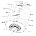
図1(A)は、一時保持ドラム式給送装置100の円筒状のドラム102の有孔部104の概略斜視図である。円筒状のドラム102全体の有孔部104に穴が開いている。有孔部104の穴は、ドラム102の外側からその内側に通じている。有孔部104は、一般に、矩形を円筒状ドラム102の外周の約2/3に巻き付けたような形状に形成される。有孔部104は、この機械で組み立てられることが予想される最大のタイヤに応じたサイズに作られる。有孔部104は、それ自体が、円筒状ドラム102と同心の円筒体であるが、円筒状ドラム102より丈が短く、円筒状ドラム102の表面の周りに部分的にのみ広がっている。図1(A)には、円筒状ドラム102の軸線106と、円筒状ドラム102の一端部を覆って密封する一方のエンドプレート110も示されている。円筒体内部の低圧力領域を維持するために、円筒状ドラム102の他端部もエンドプレート(この図では見えない)で密封されており、すなわち、円筒状ドラム102の両端部は気密状態に密封されている。円筒状ドラム102は、軸線106を中心として回転できる。
【0023】
図1(A)には、さらに、軸線106に対して角度cで幅Wの円弧を有する非有孔領域108が示されている。一時保持ドラム式給送装置100のこの円筒分割部は、移動可能な刃ガイドプレートを収容している。
【0024】
一時保持ドラム式給送装置の使用中に、タイヤのインナーライナなど、長い、平らなエラストマまたはその他のシート材をドラム上に配置(給送)し、切断するあいだドラム上に保持することができる。供給された各シート材は、所定のサイズに切断された後、タイヤ組立ドラム(図示せず)に移送される。図1(B)に、1片の平らな材料(シート材)119が円筒状ドラム102の内側と外側の間の圧力差によってその表面に保持されている状態の、図1(A)のドラム102が示されている。
【0025】
当業者には、ドラム102内への空気の流れを遮断するために、有孔面104の、平らな材料119で覆われてない部分を何らかの別の方法で覆うと、平らな材料119を確実に保持する有孔吸着面(有孔部)104を備えたこのような装置の効率を向上できることが分かるであろう。不要な空気流(漏れ)は、材料を測って取り出し、所定の長さに切断し、タイヤに組み込まれるまで材料を保持する間、シート材119を所定の位置に確実に保持することを可能にする圧力差を減少させる、好ましくない作用を有する。標準的な運転の実施では、一般に、有孔部104の、表面に保持されているシート材119で覆われていない部分は、覆われていない穴103を通ってドラム102内に入る望ましくない空気の流れを遮断するために、マスキングテープまたは他の適切なテープ(図示せず)が貼られる。
【0026】
本発明は、有孔部104の周辺領域の有効寸法の調整を容易にする。すなわち、本発明は、有孔部104の有効面積を、その端縁に沿って制御されるやり方で変更し、それによって、シート材119の小片が給送装置に配置されたときに、シート材119の置かれた領域外の穴が「漏れ口」にならない。有孔部104のこれらの部分はシート材119で覆われていないので本発明を採用していなければ空気が自由に流通するが、前記した本発明の構成では、これらの部分を覆わなくてもよいので時間を節約できる。言い換えれば、本発明は、有孔部104の、円筒状ドラム102の中へ空気を吸い込むことができるこの部分の大きさを速やかに調節する方法と装置を提供する。
【0027】
さまざまな大きさの吸着面を備えた、米国特許第4,891,082号(ブロイレスとポータルピー)に記載されている装置は、さまざまな面積の吸引面を含み、多数のポンプを必要とする。本発明は、ただ1台の空気ポンプを使用して吸着面の領域を設け、それによって構造が簡単になるという利点を有する。さらに本発明は、一様な円筒表面を備える既存の装置および方法をそのまま用いる。また、本発明は、吸着面の形態自体ではなく、有孔吸着面の、互いに異なる寸法を有する個々の平らなシート材に対する吸着力を生じる部分、すなわち領域を、制御可能なやり方で変更する装置および方法に関するものであることに注意すべきである。ある意味では、本発明は、既存の(従来の)ドラム表面自体を変更せずに、このドラム表面と一緒に使用できる。
【0028】
本発明は、2つの主な装置構成部品を含んでいる。それらのうちの一つは、有孔部104の、所定の位置に保持されているシート材119によって覆われていない(軸線方向の)側方部分を通ってドラム内に入る空気の動きを、制御可能なやり方で変更または制限するように作用する。ここで、側方部分すなわち側方領域は、有孔部104の、円筒状ドラム102の2つのエンドプレート110に最も近接する、隔たった2つの部分と定義される。図1(B)において、有孔部104の、シート材119の両側に位置する2つの部分を、ここでは側方部分と呼ぶ。第2の装置構成部品は、有孔部104の、所定の位置に保持されているシート材119によって覆われていない円筒の一部をなす部分すなわち円筒の一部をなす領域を通ってドラム102内に入る空気の動きを、制御可能なやり方で変更または制限するように作用する。ここでは、一般に、円筒の一部をなす部分すなわち円筒の一部をなす領域は、有孔部104の、円筒状ドラム102の周りに少なくとも部分的に広がっている部分すなわち領域と定義される。ここでは、例えば図1(A)において符号A、B、C、およびDで境界を定められている領域内に入っている有孔部104が、円筒状ドラム102の有孔部104の周りに部分的に広がっている円筒分割部の形状に湾曲しているので、円筒の一部をなす領域と定義される。
【0029】
図2は、有孔部104の、吸着力が1片のシート材119に作用可能な部分のサイズに応じた、前述した2つの構成部品の作用を示す一時保持ドラム102の概略斜視図である。有孔部104の2つの側方領域114a,114bは、後で詳述する、ドラム102の内側の2つの円形の障壁112a,112bが存在しているために空気が通過できない、有孔部104全体のうちの両側方部分である。円形の障壁112a,112bは、本来、軸線方向に離れている2つの円板の間の空間だけが真空となるように、ドラム102内の異なる位置に移動させることができる円板、すなわちバッフルプレートである。円形のプレート112a,112bは、穴の開いた円筒状ドラム102の内表面107の曲率半径(ri)より小さい曲率半径(re)を有している。
【0030】
両方向を指す矢印113は円形の2つの障壁(バッフルプレート)112a,112bと、障壁112a,112bが存在するために空気がドラム102内に吸い込まれない、穴の開いた、然るべき側方領域114a,114bの移動方向を示す。また、図2には、やはり一時保持ドラム102の内側に配置され、後で詳述される、金属プレート120が存在するために空気流が遮断される、穴の開いた、円筒の一部をなす部分123も示されている。
【0031】
図3は、有孔部104の外表面と内表面の間を貫通する穴103を備えた円筒状ドラム102を有する一時保持ドラム100の斜視図である。ドラムの軸線106に沿って互いに位置調節可能な2つの円形の障壁(バッフルプレート)112a,112bは、ドラム102の内側にある。円形の障壁112a,112bは対称に、すなわち互いに相手に向かったり離れたりするように移動することができる。障壁(バッフルプレート)112a,112bの相対的な移動は、左ねじまたは右ねじ(図示せず)によって一時保持ドラム式給送装置100の外部から制御される。各バッフルプレート112a,112bの周囲には、移動可能な各バッフルプレート112a,112bが円筒状ドラム102の内表面107に対して実質的に気密な封止を行うようなシール材(図示せず)が設けられており、それによって、バッフルプレート112a,112bが、軸線方向の移動中には、低摩擦で円筒体102の内部を軸線方向に移動できる。バッフルプレート112a,112bの動きは、大きさが等しいが、逆方向の、すなわち互いに相手に向かう、または離れる動きであることが好ましく、そのバッフルプレート112a,112bは、円筒状ドラム102の有孔部104の側方部分すなわち側方領域114a,114bからドラム102の内側への空気の流れを遮断するために、対称に進行する。これは、ドラム102の外表面上の材料保持領域が好ましい対称形であることを前提としている。そうでないとしても、バッフルプレート112a,112bを、適切な機構によって個別に非対称に確実に操作することが可能である。
【0032】
空気は、2つのバッフルプレート112a,112bの間の円筒状の容積部Vから抜き取られる。容積部Vから排出される空気は、軸受け台105に取り付けられた軸109と同心でその内側にある中空軸などによりドラム102の最も内側の部分および容積部Vに連通しているポンプまたは他の装置(図示せず)によって取り除かれる。吸着面が、2つのバッフルプレート112a,112bの間に収容された円筒状の容積部Vの部分における、有孔部104の内外の空気圧の差によって形成され、吸着面の側方部分は調節可能である。図3の、円筒状ドラム102の円周内の開放空間111に注意されたい。図4は、円筒分割部116に切断刃ガイド117が取り付けられた状態の、図3の開放空間111を示している。容積部Vが1つしか存在しないので、円筒状ドラム102の有孔部104の内側と外側の間に所望の圧力差を形成するために容積部Vから空気を取り除くポンプは1台しか必要ない。
【0033】
ドラム102の内側の障壁112a,112bの軸線方向の位置を調節することによって、一時保持ドラム102の有孔部104の、空気を吸引可能な部分の幅を、ドラム102に保持される個々のシート材119に必要な幅に適合するように(例えば一致するように)変更できる。すなわち、有孔部104の、シート材119のための吸着面を設けられる部分の幅方向の寸法は、内部のバッフルプレート112a,112bを軸線方向に位置調整することにより変更できる。
【0034】
言い換えれば、軸線方向にスライド可能な2つのバッフルプレート112a,112bがドラム102の内部に配置されている。バッフルプレート112a,112bの外径は、ドラム102の内径に実質的に等しい。バッフルプレート112a,112bの間の空間は、部屋(この場合は真空室V)を形成する。バッフルプレート112a,112bは、真空室Vの軸線方向の大きさを変化させ、それによって、有孔部104の、空気を中空の円筒状ドラム102に吸い込める領域の大きさを制御するために、中空の円筒状ドラム102の軸線106に沿って位置決めできる。軸線方向に移動可能な両バッフルプレート112a,112bは、それぞれが、中空で穴の開いた円筒状ドラム102の内表面107に対してスライド可能に密封されている。バッフルプレート112a,112bを互いに相手に向かうようにまたは離れるように移動させる機構が設けられている。例えば、バッフルプレート112a,112bは、移動可能な2つの円形の障壁すなわちバッフルプレート112a,112bのそれぞれの外周の周りの空気の移動を遮断する、フェルトまたは他の適切な材料から作られた外周シール材をそれぞれ有している。中空で穴の開いた円筒状ドラム102の両端部のそれぞれの内側に配置されている、軸線方向に移動可能なバッフルプレート112a,112bは、互いに相手に向かうように、または離れるように動くことができ、それによって、有孔部104の、空気を吸い込むことができる中央領域の幅を変化させ、中空で穴の開いた円筒状ドラム102の外側の吸着面104を形成できる。
【0035】
図4に、図3に示されているものと基本的に同じであるが、エンドプレート110が外され、円筒分割部116の所定の位置に切断刃ガイド117が固定された状態の一時保持ドラム式給送装置100が示されている。図4には、円筒を分割した形状を有する金属プレート120と、支柱124によって金属プレート120に連結されている中心軸109とからなる装置121も示されている。
【0036】
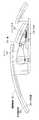
図5に、装置121をドラム102の外側に出して(ドラム102から分離して)単独で示している。装置121は、中心軸109を中心として曲率半径Rを有する、円筒を分割した形状を有する金属プレート120からなる。曲率半径Rは、穴の開いたドラム102の内表面107の曲率半径よりわずかに小さい。金属プレート120は支柱124によって中心軸109に取り付けられている。装置121の、両支柱124の最も離れている個所の間の部分の全長は、円筒状ドラム102の長さより短い。
【0037】
図4には、穴103を備えた有孔部104を有するドラム102の内側に取り付けられた装置121が示されている。図4には、ドラム102の内側の一方の障壁112aも示されている。円形の障壁112a(および図示されていない障壁112b)は、ドラム102の内側で軸線106に沿って軸線方向に動くように構成されていることに注意されたい。2つの障壁112a,112bのそれぞれの周囲から外側に広がっている前述のシール材は、両障壁112a,112bの周囲と、円筒ドラム102の有孔部104の内表面107との間を、容認できない程度の空気が流れるのを防ぐように密封することができる。2つの障壁112a,112bの周囲のシール材は、装置121の薄い金属プレート120に支えられて動くことも可能である。
【0038】
図5は、軸線方向に動く2つの円形の障壁112a,112bと同様に、一時保持ドラム102の内部に配置された、前述した円筒の一部をなす形状のプレート支持・移動装置121の斜視図である。金属プレート120は、穴の開いたドラム102の内表面107の曲率半径よりわずかに小さい、中心軸109を通る軸線106からの曲率半径Rを有する、円筒を分割した形状を有している。金属プレート120は、支柱124によって中心軸109に取り付けられている。装置121の、両支柱124の最も離れている箇所の間の部分の全長Lは、ドラム102の内表面107の長さより短い。
【0039】
金属プレート120がドラム102の内側に配置され、金属プレート120がドラム102の有孔部104の内側に隣接しているとき、その部分において外側からドラム102内への空気の移動は妨げられる。すなわち、金属プレート120は、有孔部104の、硬質の薄いシート材で作られている金属プレート120によって覆われている部分を通ってドラム102内へ入る空気流を遮断する。
【0040】
金属プレート120は、ドラム102の中心に向かって内側に撓むことなくドラム102の内側と外側の間の圧力差に耐えるために、薄い硬質の材料で作られていることに注目することが重要である。機械設計技術の知識を有する者であれば、金属プレート120の、円筒を分割した形状が、圧力差に耐える際の薄い金属プレート120の剛性に寄与することが判るであろう。
【0041】
図5を参照すると、手動クランク128、またはモータに制御される軸が、金属プレート120を支持する装置121に、角度運動とドラム102の内側の所定の角度位置とを伝達することを可能にする機構126が設けられているのが示されている。
【0042】
一時保持ドラム102内への開口部分103の、横方向のサイズおよび円筒の一部をなす形状のサイズをともに制御することによって、ドラム102の有孔部104の、空気をドラム102内に吸い込むことができる部分の寸法を、制限、調整、または変更することは、本発明の範囲内である。円形の2つの障壁(バッフルプレート)112a,112b(図3と4参照)は、金属プレート120の両支柱124間の部分内で軸線方向に動くようになっている。金属プレート120の薄さは、障壁(バッフルプレート)112a,112bの外周シール材がプレート120を受け入れ、外周シール材がプレート120に当接して上に乗ってスライドする部分に接する部分で、障壁112a,112bの周囲の望ましくない空気流を十分に封止できるような薄さである。
【0043】
中空の円筒状ドラム102の内側に配置されている、周方向に移動可能な、円筒状に湾曲している金属プレートすなわち構成部品120は、中空の円筒状ドラム102の軸線と連続する回転軸109を有し、中空の円筒状ドラム102の内側の円筒状の容積部Vの長さより短い長さを有し、その最も外側の曲率半径は、中空で穴の開いた円筒状ドラム102の内表面107の曲率半径とほぼ等しい。周方向に移動可能な、円筒状に湾曲している構成部品(金属プレート)120は、その構成部品(金属プレート)120の回転軸109に関して約60度〜約120度、好ましくは約80度〜90度の範囲内の幅の円弧を有している。
【0044】
言い換えれば、穴の開いた円筒状ドラム102の内表面107に一致する曲面状の、周方向に移動可能な円筒分割部120が、中空のドラムの内側にある。中空の円筒状ドラム102に空気を吸い込むことができる有孔部104の大きさは、曲面状の円筒分割部120を、中空で穴の開いた円筒状ドラム102の内表面107の部分に接するようにして周方向に位置決めすることによって変更される。
【0045】
(前述したように)本質的には、円筒状ドラム102の周囲の約50%〜80%、好ましくは約60%〜70%に巻き付けられる矩形であるような有孔部104を想定することが有効である。有孔部104は、機械で組み立てられることが予期される最大のタイヤに基づいたサイズに形成される。この矩形は、円筒状ドラム102の周りに周方向に部分的に延びている長さと、水平に配置された円筒状ドラム102すなわち一時保持ドラム式給送装置100の軸線方向の長さのほとんどにわたって延びる幅を有する。本発明の作用により、材料を測って取り出し、所定の長さに切断し、タイヤに組み込まれるまで材料を保持する間、製造されるタイヤのサイズに必要な、一時保持ドラム式給送装置100の表面に保持されることが望まれる平らなシート材片119の大きさに基づいて、矩形の有孔部104の「有効な」幅および/または長さを増減できる。
【0046】
[一時保持ドラムの切断部]
穴の開いた外表面と、ドラム102の表面の、ドラム102の表面に置かれたシート材119に吸引力を及ぼす領域を規定する、軸線方向に移動可能な円板状の2つのバッフルプレート112a,112bと、中空の円筒状ドラム102内へ空気を吸い込むことができる有孔部104の大きさをさらに調整するための、周方向に移動可能な、ドラム102の内表面107と一致する曲面状の円筒分割部とを有する。
【0047】
図4に、切断刃ガイドを有する円筒分割部が示されている。一般的な考えでは、シート材119を一時保持ドラム102の表面に配置し、それから所定の長さに切断する。ここで、本発明の一時保持ドラム102の切断部について詳しく説明する。
【0048】
以下に記載される切断部は、前述した一時保持ドラムに従属するのではなく、前述した一時保持ドラムに一体化するのに非常に適したものであると理解されるであろう。この切断部は、他の一時保持ドラムと一緒に働くことも可能である。多くのタイヤ組立機械が、多くの構成部品のために一時保持ドラム式給送装置を使用している。一時保持ドラムは基本的に円筒面であり、その円筒面上において、タイヤ組立用の構成部品が必要な長さだけ測られて取り出され、切断され、構成部品がこの円筒面からタイヤ組立ドラムに付与(移送)される。構成部品は、一般にエラストマ材料のシート(中にコードが埋め込まれているプライ材など)であり、多くの場合は、(前述したように)一時保持ドラムの内側から空気を吸い出すことによって生成される真空によって一時保持ドラムに付着させられる。円筒外表面を貫通する小さい穴、すなわち多孔質材料によって、ゴム製の構成部品を外表面に吸着することが可能になる。エラストマ材料は、長さ方向に一時保持ドラム上まで送られる。エラストマ材料の幅は、ドラムの軸線方向である。材料の幅は、完成品のタイヤのビード間の寸法(両サイドウォールに沿ってトレッドを横切って測定したときの寸法)に概ね一致している。
【0049】
一時保持ドラム上で切断する必要がある一般的なタイヤ構成部品は、エラストマ層にコードが埋め込まれているプライ材である。プライ材は周知である。プライ材をその必要な長さに切断するために、加熱された刃(カッター、すなわち切削工具の一種)が、プライ材の、材料の幅方向の中央のコードの間に突き刺される。それから刃は、材料の縁端を越えて外方に引かれる(後退させられる)。これが、この種の材料を切断するための確実な方法であることは立証されており、ゴム業界全体で公知である。
【0050】
この種のカッターを一時保持ドラム式給送装置上で使用するには、切断される材料にナイフが貫通するための溝すなわち開口部が設けられていなければならない。中にコードが埋め込まれているプライ材に関しては、プライ材内のコードは、さまざまなタイヤ構造ごとに異なる角度で配置されていることがある。例えば、コードが0度、すなわち一時保持ドラムの軸線に平行に向けられていることもあり、あるいは、コードがドラムの軸線に対して(いずれかの方向に)例えば10度以下傾いていることもある。以下に、主にコードを有するプライ材である切断材料について論じるが、本発明はプライ材の切断のみに限定されるものではないことを理解すべきである。
【0051】
図6(A)は、従来技術の一時保持ドラム200の部分断面図である。ドラム200は、前述したように、穴(図示せず)が開いていてもよい外表面202を有する。ドラム200の外表面202には、溝204が設けられている。溝204は、ドラム200の円筒表面の端部から端部まで概ね軸線方向に延びている。
【0052】
エラストマ材料のシート206が外表面202の上に示されており、溝204の上に覆い被さっている。溝204から(ドラム200に対して)半径方向外側に配置され、材料206を溝204の位置で切断するように準備されているナイフブレード208の形態の切削工具が(実線で)示されている。また、材料206を貫通し(突き通し)、それによって材料206を所望の長さに切断するナイフブレード208が、破線で示されている。また、この図には、材料206に埋め込まれたコード210も示されている。コード210は角度0度で示されている(ドラムの軸線に平行に、すなわち材料206の幅を横切ってまっすぐに延びている)。ナイフブレード208は、適宜にコード210の間を通る。したがって、ナイフブレード208は(ドラム200の軸線に対して)コード210とほぼ同じ角度にすべきである。一般に、ナイフブレード208はコード210を切断しないように位置決めされる。加熱された刃、水の噴射、振動ブレード、針、およびレーザ等を含む、他の切削工具を使用してもよい。
【0053】
プライ材のコード210は、角度を有していても(すなわち、ドラム200の軸線に平行でなくても)よい。例えば、前述した米国特許第4,504,337号に示されているように、測定ドラムは「ある長さのプライ材を切断するためにカッター[刃49]が沿って移動できる斜めの線20」を備えている。
【0054】
一時保持ドラムは、一般に、さまざまな構成部品の組立体である。切断用溝204は、一般に、ここでは「切断部」と呼ばれている一時保持ドラムの構成部品に含まれている。どのようなコード角度に対しても、溝を備えたドラム分割部を交換する必要がなく、ある範囲のコード角度(すなわちナイフブレードの角度)に適応可能にするために、溝は、少なくともある範囲の角度をカバーする十分な広さを備えている必要がある。その角度の範囲が広い場合には、広い溝が必要になる(溝の幅は、ドラムの周方向に測定される)。しかしながら、幅広の溝は、プライ材(または任意の材料)が切断された後、溝上に張り出す(覆い被さる)プライ材の切断端部が、タイヤ組立ドラムへのプライ材の移送中に一時保持ドラムの外表面によって支持されないという問題を引き起こす。移送が信頼できなくなることとは別に、空気通路がタイヤのこの場所に形成され、最終的な結果としてタイヤの欠陥を生じることがある。
【0055】
溝の一般的な目的は、金敷の目的と本質的に反対であることが理解されるであろう。金敷はまな板のようなものである。一斤のパンを切るときには、パンをまな板の上に置いてナイフでスライスするが、(調理台の上にある)まな板は、ナイフによって及ぼされる力に対して抵抗する力を生じる。溝の場合、前述したタイヤ材料を切断するために切削工具が使用され、切削工具の端部(すなわち先端)が抵抗なく溝内に受け入れられることが望ましい。一般に、溝が不要であれば、以下に説明するように、溝を露出させたり隠したりするために選択的に開閉可能なドアパネルは必要ではない。
【0056】
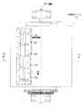
(図4と同様な)図6(B)には、一時保持ドラム220が図示されている。ドラム220は円筒形であり、軸線222を有している。ドラム220は、所望の長さに切断するためにプライ材(図示せず)を保持する外表面に、穴228を有している。ドラム220を概ね軸線方向に横切って延びる「蝶」型の溝224が示されている。溝224は、ドラム220の(軸線方向の)中央において周方向に最も狭くなり、ドラム220の両端部に向かって周方向に広くなっている。溝224は、基本的に、ドラム220の中央において互いに交差する2本の直線で形成されており、一方の直線は軸線222に対して小さい正の角度(例えば10度以下)だけ傾けられ、他方の直線は軸線222に対して、相応する小さい負の角度(例えば−10度以下)だけ傾けられている。溝224がドラム220の中央付近で周方向に狭くなることは図7(A)の断面図からも明らかであり、また、ドラム220の中央から離れると周方向に広くなることは図7(B)の断面図からも明らかである。溝224は、ドラム220上の「切断位置」と呼ばれる部分に配置されている。
【0057】
その結果、本発明が取り組んでいる課題の概要は、一時保持ドラムの外表面に、半径方向内側に延びる溝の形の切れ目を有することである。周方向に非常に狭いただ1つの溝を設けるのは許容されるが、ある範囲のコード角度に適応するために周方向に広い溝(蝶型の溝224を含む)は、結果的に、溝に覆い被さるプライ材の切断端部が支持されないため、通常は許容できない。したがって、本発明の目的は、一時保持ドラムの切断用溝の領域内で支持されないプライ材があるという問題を解決することにある。
【0058】
本発明は、以下にさらに詳しく説明されるように、構成部品を切断するときには溝を開ける(露出させる、見せる)が、それ以外の場合には溝を閉じた(隠された、見えない)状態に保つ機構を導入することによって、材料端部が支持されないという問題を解決する。
【0059】
(図6(B)と同様な)図8に、一時保持ドラム300が図示されている。ドラム300は円筒形であり、軸線302を有している。ドラム300は、理解しやすく図示するために、穴(例えば128)を省いて示されている。ドラム300は、ドアパネル322を取り除いた状態で示されている。ドアパネル322は、図9と図10に関連して詳細に図示および説明される。図9と10は、異なる2つの状態のドラム300を図示する断面図であり、図9は、ドアパネル322が開き、切断用溝330が露出した状態であり、図10は、材料を一時保持ドラム300にくっつけるため、すなわち切断された材料を一時保持ドラム300からタイヤ組立ドラム(図示せず)に移送するために、ドアパネル322が閉じられた(溝330が隠された)状態である。本実施形態では、ドラム300は、その外表面304が、薄い規格のタイヤの構成部品に適したフェルト(または同様の材料)などの多孔質材料306、または、より厚い規格のタイヤの構成部品に適した発泡ゴム(例えばネオプレン、シリコンゴム、ポリウレタンフォーム)で覆われているように示されている。
【0060】
本発明は、一般に、溝330と、前述した理由により、溝330である切れ目によってドラム300の円筒外表面304が途切れないように溝330を選択的に閉じる(覆う)パネル(ドアパネル)322を有する。本発明は、周方向に広い概ね矩形の溝や、前述したような「蝶」型の溝など、本質的に、任意の角度の、任意の大きさおよび/または形状の溝330に適用できる。溝330を覆う(隠す)ドアパネル322は、ちょうど家のドアが戸口(ドアフレーム)と実質的に同じ(一般に矩形の)大きさおよび形状を有しているのと同じように、溝330と実質的に同じ大きさおよび形状を有している。
【0061】
図9と図10に最もよく示されているように、一時保持ドラム300の溝330を選択的に開閉する機構320は、
細長いレバー324を有し、ドアパネル322がレバー324の一端部に支持され、
レバー324の他端部が、ドラム300の適切な固定部分(固定点)に、ピボット運動するように取り付けられており、
ドアパネル322の内表面とドラムの他の固定部分(固定点)との間に延びているばね326と、
レバー324とドラムの他の固定部分(固定点)との間に配置された空気チューブ328を有している。
【0062】
この実施形態では、ばね326は、直前に記載された構成部品324,326,328の構成により、パネル322を、図9に示されている開放位置に向けて付勢している。ドアパネル322は「通常は開いている」。溝330は、通常は見えている(露出している)。(一時保持ドラムでは普通は考慮しない遠心力を含む)他の何らかの力が存在しない場合、ドアパネル322は開いたままで、ドラム300の表面に溝330(204と同様)が見えている。溝330は、図6(A)に関連して先に説明したように、切削工具(例えば208)が、ドラム表面に配置されている材料(例えば206)を貫通できるようにするためのものである。ドアパネル322が開いた状態で、ドラム300の表面に配置されている材料は切断可能である。この場合、「溝」330は、本質的に、機構320を収容するポケットである。
【0063】
ドラム300の表面に配置された材料が切断された後、余分の材料(切れ端)が取り除かれ(廃棄または再利用され)、溝330に覆い被さっている材料の切断端部(縁端)は支持されていない。切断端部が溝330に垂れ下がって問題を生じる可能性がある。したがって、ドアパネル322が、図10に示されるようにその閉鎖位置に移動される。この実施形態では、直前に説明された部品構成の場合、この問題の解決は、膨張時に直径が増大してレバー324の下側に上昇力を及ぼす空気チューブ328を膨張させ、それからレバー324の自由端部が(ドラム300に対して)半径方向外側に移動され、それによってドアパネル322がその閉鎖位置に移動され、その結果、ドアパネル322の外表面がドラム300の外表面と連続することによって達成される(チューブ328は「消火ホース」原理と呼ばれることがある原理に基づいて作用する。内部に流体圧がなければチューブ328はつぶれる。流体圧があればチューブ328は膨張状態となる。この原理は迅速かつ制御可能な方法で行われる)。この作用は、溝330内に垂れ下がる可能性のある材料の端部を持ちあげる効果があり、いずれにしても、ドラム300の外側に、(ドアパネル322を閉じた状態で)溝330の切れ目が見えない連続的な表面を形成する。ドアパネル322の外表面は、ドラム300の表面を覆っているのと同じ多孔質材料306で覆ってもよい。これにより、(ドアパネル322が閉じられたときに)一時保持ドラム300の周囲に均一な特性を備えた欠けのない表面が形成される。
【0064】
図10に最もよく示されているように、ドアパネル322は、その側端縁(図で見ると右側)が先細になっているので、移動し過ぎるのが防止される(ドアパネル322は、開口部に対する大きさおよび形状と、レバー324の端部に取り付けることにより移動を制限する方策とによって、円筒状ドラム300の外表面を越えてピボット運動することが全くできない)。ドアパネル322がドラム300の表面と同じ高さになると、ドアパネル322は半径方向外側にそれ以上移動できないようになっている。いずれにしても、チューブ328は、チューブ328が十分に膨らんだときにドアパネル322が行き過ぎることも進み足りないこともなく完全に閉鎖位置に位置するように、容易に寸法と位置が決められる。本発明の範囲内で、ドアパネル322をドラム300の表面と同じ高さになる位置に正確に停止させるために、(ドア側面の刳り形と類似の)より「積極的な」停止機構を設けることもでき、その場合、ドアパネル322に閉じる力を及ぼす機構(例えばチューブ328)は、ドアパネル322が閉じているのが望まれるときにドアパネル322が自ら確実に閉じた状態でいるように、ドアパネル322に必要以上の力を及ぼす構成にすることもできる。
【0065】
図8に、溝330の長さ方向(切断される材料の幅方向)に沿って実質的に等しい間隔をおいて分布する、複数の(例えば5つの)機構320が示されている。これは、一般に、溝330の長さ方向(軸線方向)に沿って均一な閉じる力をドアパネル322に確実に及ぼすものであり、各機構320を、総荷重のうちの一部だけに対応する構成にすることが可能になり、それによって、個々の機構320に課せられる、サイズ上の制約が緩和される。本発明の範囲内で、任意の数の機構320、または、ドアパネル322を開閉するための(以下に簡単に記載される)別の機構、または複数の(以下に簡単に記載される)ドアパネルを使用することもできる。
【0066】
本発明の範囲内で、溝を開閉するために複数のドアパネルを使用することもできる。例えば、本質的に頂点と頂点が一致する2つの三角形部分を有する蝶型の溝に関しては、溝の一方の三角形部分を一方のドアパネルで開閉することができ、溝の他方の三角形部分を他方のドアパネルで開閉することができる。複数のドアパネルのそれぞれに別個の機構を設けることもでき、複数のドアパネルを作動させるために1つの共通の機構を使用することもできる。
【0067】
使用時における作動の順序の具体例は次の通りである。
(a)最初にドアパネルが(任意に)閉じられる。
(b)材料が、(測られて)切断されるためにドラムの上に置かれる。
(c)ドアパネルが(まだ開いていなければ)切断するために開かれる。
(d)切削工具が材料を切断する。
(e)余分の(切り離された)材料が(任意に)取り除かれる(廃棄される)。
(f)ドアパネルが閉じられる。
(g)切断された材料が従来と同じ方法でタイヤ組立ドラムに移送される。
【0068】
前述した実施形態では、ドアパネル322を開閉するための基本機構320は、レバー324と、ばね326と、膨張可能なチューブ328とを有し、この基本機構320は、溝330の全体にわたって、ドアパネル322の開閉を、要求に応じて何回も繰り返すことができる。本発明の範囲内で、空気圧シリンダ、電気モータ、機械的カム等のような、別のタイプの機構も使用できる。
【0069】
本発明は、選択される機構に関係なく、様々なタイヤ構造の様々なコード角度に対して様々な一時保持ドラム切断部を用いる必要性を排除するものである。また、構成部品をタイヤ組立ドラムに供給する前に溝を閉じることによって、タイヤの欠陥の原因が解消される。構成部品の移送の、より高い信頼性が必然的に達成される。
【図面の簡単な説明】
【図1】(A)は穴の開いた円筒状ドラムの概略斜視図、(B)は図1(A)のドラムの、平らなシート材が有孔部に保持されている状態を示す図である。
【図2】有孔部の、空気流が遮断されている、または遮断されていない部分を示す、中空で穴の開いた円筒状ドラムの概略斜視図である。
【図3】切断刃ガイドが取り外されて、軸線方向に移動可能な円形プレートが現れている、中空で穴の開いた円筒状ドラムの斜視図である。
【図4】切断刃ガイドは所定の位置にあるが、一方のエンドプレートが取り外されて、軸線方向に移動可能な円形プレートと、周方向に動く、円筒の一部をなす形状のプレートが現れている、中空で穴の開いた円筒状ドラムの斜視図である。
【図5】穴の開いたドラムの内側に嵌め込まれる、円筒の一部をなす形状のプレートとその支持構造の斜視図である。
【図6】(A)は従来技術による一時保持ドラムの一部を示す断面図、(B)は本発明による一時保持ドラムの平面図である。
【図7】(A)は、本発明による図6(B)の一時保持ドラムの一部を6B−6B線で切った断面図、(B)は、本発明による図6(B)の一時保持ドラムの一部を6C−6C線で切った断面図である。
【図8】本発明による一時保持ドラムの平面図である。
【図9】開放位置にある、本発明による図8の一時保持ドラムの一部を7B−7B線で切った断面図である。
【図10】閉鎖位置にある、本発明による図8の一時保持ドラムの一部分を7B−7B線で切った断面図である。
【符号の説明】
100 一時保持ドラム式給送装置
102 円筒状のドラム(一時保持ドラム)
103 穴
104 有孔部
105 軸受け台
106 軸線
107 内表面
108 非有孔領域
109 中心軸
110 エンドプレート
111 開放空間
112a,112b バッフルプレート(円形の障壁)
113 矢印
114a,114b 側方領域
116 円筒分割部
117 切断刃ガイド
119 シート材(平らな材料)
120 金属プレート(円筒分割部)
121 プレート支持・移動装置
123 円筒の一部をなす部分
124 支柱
126 伝達機構
200 従来の一時保持ドラム
202 表面
204 溝
206 シート材
208 ナイフブレード(切削工具)
210 コード
220 一時保持ドラム
222 軸線
224 蝶型の溝
228 穴
300 一時保持ドラム
302 軸線
304 外表面
306 多孔質材料
320 開閉機構
322 ドアパネル
324 レバー
326 ばね
328 チューブ
330 溝
V 円筒状の容積部[0001]
BACKGROUND OF THE INVENTION
The present invention relates to a method and apparatus for use in preparing materials used in the assembly of pneumatic tires. In particular, the present invention provides a "False Drum" type feeder that holds tire building material (e.g., an elastomer sheet) while being cut prior to transfer to the tire building drum.A temporary holding drum suitable for cutting and material cutting methodRelated.
[0002]
[Prior art]
For example, when making a tire for a vehicle such as an automobile, it is known to produce a so-called carcass by first incorporating several different components one after another. In other words, different types of carcasses contained in a product group can be distinguished from each other depending on the presence or absence of various accessory components and / or the type of accessory components themselves. As an example, when manufacturing a tubeless tire, i.e. a carcass for a tire that does not require the presence of an inner tube when in use, the main components are a so-called inner liner, which is a layer of elastomeric air-impermeable material, and a carcass ply. The pair of annular metal members, generally referred to as bead cores, is considered to include a pair of annular metal members, both ends of the carcass ply, and made of an elastomer material and extending to both sides beyond the carcass ply. Encased in a pair of sidewalls. The accessory component includes one or more additional carcass plies and one or more reinforcements overlying an area of the carcass ply that is folded around the bead core. A band (chafer strip) or the like may be incorporated in order.
[0003]
In some tire assembly lines, various types of feeders are used to reliably hold flat materials such as tire inner liners when they are cut to a predetermined size. Feeding devices are generally those shown in British Patent No. 1,010,597 (Dunlop Rubber Company), or transport a continuous flat sheet of material on a flat conveyor to a cutting blade, and then A flat conveyor type, such as the conveying and cutting system shown in US Pat. No. 4,722,255 (Chote et al.), Where material is removed and placed on the tire to be assembled. Yet another conveyor system is taught in US Pat. No. 5,820,726 (Yoshida et al.) That incorporates a “transfer drum” member that feeds material to the conveyor system.
[0004]
Drum feeders, or so-called “temporary holding drum” feeders, are not securely held while measuring and taking out the material, cutting it to a predetermined length and holding the material until it is incorporated into the tire Another conveyor system for flat, sheet-like tire material that must not be. After being cut, the sheet material is moved to the tire being assembled by the assembly drum. In general, such a temporary holding drum type feeding device is composed of a horizontally arranged drum, that is, a cylindrical body, which can rotate around an axis of the cylinder. One particular temporary holding drum type feeder is composed of a hollow cylindrical drum. The surface of the drum is perforated at 50 to 80 percent, preferably 60 to 70 percent, and most preferably 66 percent of its outer circumference, and a sufficient amount of air is pumped out of the drum to pass through the drum. By applying a low pressure, a suction surface is provided that can reliably hold a flat or sheet-like material that is cut while being held by the feeder. When a flat sheet material, such as an inner liner of a tire, is placed on the perforated cylindrical portion of the feeder, the flat material is caused by a pressure difference between the inside and outside of the drum while the material is being cut. Is attached to the drum surface.
[0005]
Another drum feeder that similarly holds flat material on a cylindrical surface is taught in US Pat. No. 4,504,337 (Ascam et al.), Which is held for cutting. A drum-type feeding device is described in which a flat material is securely held by a magnetic surface. However, such devices are of course limited to use for flat or sheet-like tire materials, including steel or ferromagnetic members, such as wires, cords or metal cloths. .
[0006]
A temporary holding drum feeder of the type described above that draws air through a perforated cylindrical surface as a way to reliably hold the material to be cut is used with a flat sheet material that is not magnetic. Suitable for In addition, the United States that describes the "set of vacuum cups spaced circumferentially" surrounding the outer periphery of the "transfer roll", which mainly fulfills the same purpose as the temporary holding drum type feeding device described above. The vacuum cup method taught in US Pat. No. 4,891,082 (Broiles and Portalpy) is also suitable. The vacuum cup is individually pumped by a compressed air motor.
[0007]
The adsorbing part of a temporary holding drum type feeding device of the type having a drum with a hole is the surface of a cylindrical drum with a hole. The temporary holding drum feeder has a substantially larger diameter than the assembly drum. The sheet rubber is measured for the required length with a temporary holding drum feeder and then cut before being transferred to the assembly drum. Since the cylindrical surface becomes a suction surface due to the pressure difference between the inside and outside of the cylindrical surface with the hole, the elastomer sheet, that is, the flat material disposed on the temporary holding drum is held by the temporary holding drum type feeding device.
[0008]
[Patent Document 1]
British Patent No. 1,010,597
[Patent Document 2]
U.S. Pat. No. 4,722,255
[Patent Document 3]
US Pat. No. 5,820,726
[Patent Document 4]
US Pat. No. 4,504,337
[Patent Document 5]
US Pat. No. 4,891,082
[0009]
[Problems to be solved by the invention]
Temporary holding drum feeders are generally faster than conventional conveyors, ie belt-type (flat) feeders or roller conveyors, in that they can increase the speed at which flat sheet material is cut. Has advantages. However, the drawback of the temporary holding drum feeder is that in the case of flat components such as inner liners and plies, the portion of the cylindrical surface with holes that is not covered by the flat material to be cut is It is open so that air can freely flow into the drum. Such a free flow of air weakens the pressure difference that holds the sheet material to the drum (the uncovered holes become “leaks”). One approach to addressing this leakage problem is simply to use an adhesive tape or other material to block the air flow through the perforated surface that is not covered by the flat sheet material. Yes (in other words, to close the hole). However, the various pieces of material to be cut are often of different sizes, so that typically occurs when changing from a large tire component to a smaller component, but maintains the low pressure inside the drum. The tape or other material that interrupts the air flow must be removed and replaced so that it is possible (if the vacuum suction is desired to hold the material, it is not desirable to plug the hole). However, the time required to dispose the tape on the unused portion of the perforated surface area or to remove the tape later is not preferable. The method of plugging the holes with the tape may otherwise cause the tire components to become soiled by pieces of adhesive tape that are loose and adhere themselves to the tacky uncured elastomeric material.
[0010]
An alternative to using tape is to use an oversized large air pump to remove air from the interior of the temporary holding drum. If a sufficiently large air (vacuum) pump is used, holes (leakage) will not be a problem. However, an unnecessarily large pump is not preferred in terms of energy consumption and environmental considerations, as well as overall capital costs and operating costs. Another solution is proposed in the aforementioned U.S. Pat. No. 4,891,082 (Bloiles and Portalpy) for each vacuum cup used to hold the sheet material on a cylindrical surface. The use of individually controllable vacuum pumps is disclosed. However, with this method, it is possible to form an adsorption surface that can quickly cope with economical operation and when the surface area of a specific flat sheet material held on a cylindrical surface by suction force is different. In order to achieve both, it is necessary to use complex control mechanisms to control the individual vacuum pumps.
[0011]
The present invention particularly relates to a temporary holding drum suitable for a temporary holding drum type feeding device of the type described above, which has a perforated surface for holding a sheet material.And how to cut the material on itThe purpose is to provide.
[0012]
[Means for Solving the Problems]
According to the present invention,A temporary holding drum having a cylindrical drum, a groove, a door panel, and a mechanism for selectively opening and closing the groove, the cylindrical drum having a material placed thereonCut to the required lengthPerforatedCylindrical outer surfaceAnd a rotational axis extending through the cylindrical drum,The grooveA cut in the cylindrical outer surface of the cylindrical drum that extends radially inward and passes through the cylindrical outer surface;materialofThe part that covers the grooveCutting toolsSize and shape that can penetrateAnd the circumferential width is the narrowest at the center of the cylindrical drum, and the circumferential width increases toward both ends of the cylindrical drum.grooveSame asSize and shapeThe mechanism isDoor panelUse the groove selectivelyOpen and closeThus, a temporary holding drum is provided, characterized in that the outer surface of the door panel is continuous with the outer surface of the drum when the groove is closed.
[0013]
According to an embodiment of the present invention, the groove is a butterfly shape having two triangular portions extending generally across the drum in an axial direction and arranged so that the apexes coincide.
[0014]
According to the embodiment of the present invention, a plurality of door panels may be used, and a plurality of mechanisms for operating the plurality of door panels may be used.
[0015]
In an embodiment of the present invention, the door panel isUsing grooveA mechanism that opens and closes selectively includes an elongate lever with one end supporting the door panel and the other end pivoted to a fixed part (fixing point) of the drum, and another fixing of the inner surface of the door panel and the drum A spring extending between the part (fixing point) and an inflatable air tube arranged between the lever and another fixing part (fixing point) of the drum.
[0016]
According to an embodiment of the present invention, a plurality of such door panel actuation mechanisms may be distributed at equal intervals along the length of the groove. Another door panel actuation mechanism is described.
[0017]
The present invention opens the groove when cutting the material and closes the groove when not cutting the material (e.g., before the material is cut and / or after the material is cut), thereby cutting the temporary holding drum. Supports material covered byCan cutProvide a method. Importantly, after the material has been cut, the door panel closes the groove so that the end of the cut material is supported without hanging down into the groove, thereby ensuring that the material is reliable to the tire building drum It is to be transported highly.
[0018]
DETAILED DESCRIPTION OF THE INVENTION
Reference will now be made in detail to the preferred embodiments of the present invention, examples of which are illustrated in the accompanying drawings. The drawings are for illustrative purposes and do not limit the invention. While the invention will be broadly described in connection with these preferred embodiments, it should be understood that it is not intended to limit the spirit and scope of the invention to these specific embodiments.
[0019]
Certain elements in the selected drawings may be described at different scales for clarity of illustration. In the cross-sectional view shown here, for the sake of clarity, the “thinly sliced cross-sectional view” or “the cross-sectional view of the adjacent portion is omitted, omitting the back side line that should be visible in the actual cross-sectional view. ".
[0020]
The structure, operation and advantages of preferred embodiments of the present invention will become more apparent in light of the following description taken in conjunction with the accompanying drawings.
[0021]
The temporary holding drum type feeding device is mainly composed of a hollow and perforated cylindrical body (drum) having a diameter substantially larger than that of the tire assembly drum. The drum can rotate about its axis. The cylindrical portion of the drum is perforated (having holes) over 50-80%, preferably about 66%, of its cylindrical surface, and both ends of the drum are driven by an air pump that removes air from the drum. It is sealed so that air does not flow except when air flows from the inside. Because the internal pressure is small relative to the outside air pressure, air moves through the perforated surface and into the drum. In this specification, the term “drum”, the term “measurement drum” and the term “temporary drum” are specifically stated unless the term “drum” is specifically referred to as an element or component of a temporary holding drum feeder. The term “holding drum” type feeder is considered synonymous.
[0022]
FIG. 1A is a schematic perspective view of the
[0023]
FIG. 1A further shows a
[0024]
When using a temporary holding drum feeder, a long, flat elastomer or other sheet material such as a tire inner liner can be placed (feed) on the drum and held on the drum while it is being cut. . Each supplied sheet material is cut into a predetermined size and then transferred to a tire assembly drum (not shown). FIG. 1B shows a drum in FIG. 1A in which a piece of flat material (sheet material) 119 is held on the surface by a pressure difference between the inside and outside of the
[0025]
Those skilled in the art will ensure that the
[0026]
The present invention facilitates adjustment of the effective dimension of the peripheral region of the
[0027]
The device described in U.S. Pat. No. 4,891,082 (Brauilles and Portalpies) with various sized suction surfaces includes various areas of suction surfaces and requires multiple pumps . The present invention has the advantage that only one air pump is used to provide the area of the adsorption surface, thereby simplifying the structure. Furthermore, the present invention uses existing devices and methods with a uniform cylindrical surface as they are. Also, the present invention provides an apparatus for changing in a controllable manner the portion, i.e., area, of the perforated adsorbing surface that produces an adsorbing force on individual flat sheet materials having different dimensions rather than the adsorbing surface configuration itself. It should be noted that the method and method. In a sense, the present invention can be used with this drum surface without altering the existing (conventional) drum surface itself.
[0028]
The present invention includes two main device components. One of them is the movement of air entering the drum through the side part (in the axial direction) of the
[0029]
FIG. 2 is a schematic perspective view of the
[0030]
[0031]
FIG. 3 is a perspective view of the
[0032]
Air is extracted from the cylindrical volume V between the two baffle plates 112a and 112b. The air discharged from the volume V is concentric with the
[0033]
By adjusting the axial positions of the barriers 112 a and 112 b inside the
[0034]
In other words, two baffle plates 112 a and 112 b slidable in the axial direction are arranged inside the
[0035]
4 is basically the same as that shown in FIG. 3 except that the
[0036]
FIG. 5 shows the
[0037]
FIG. 4 shows a
[0038]
FIG. 5 is a perspective view of a plate supporting / moving
[0039]
When the
[0040]
It is important to note that the
[0041]
Referring to FIG. 5, a manual crank 128, or a shaft controlled by a motor, allows to transmit angular motion and a predetermined angular position inside the
[0042]
Air is sucked into the
[0043]
A circumferentially movable, cylindrically-curved metal plate or
[0044]
In other words, there is a curved, circumferentially movable
[0045]
It is envisioned that the
[0046]
[Cutting section of temporary holding drum]
Two axially displaceable baffle plates 112a defining a region that exerts a suction force on the outer surface of the
[0047]
FIG. 4 shows a cylindrical division having a cutting blade guide. The general idea is that the
[0048]
It will be understood that the cutting section described below is very suitable for integration into the temporary holding drum described above, rather than being dependent on the temporary holding drum described above. This cutting part can also work together with other temporary holding drums. Many tire building machines use temporary holding drum feeders for many components. The temporary holding drum is basically a cylindrical surface, on which the components for tire assembly are measured and taken out to the required length, cut, and the components are transferred from this cylindrical surface to the tire assembly drum. Granted (transferred). The component is typically a sheet of elastomeric material (such as a ply material with a cord embedded in it), often produced by sucking air from the inside of a temporary holding drum (as described above). It is attached to the temporary holding drum by vacuum. A small hole penetrating the outer surface of the cylinder, ie a porous material, makes it possible to adsorb rubber components on the outer surface. The elastomer material is fed in the length direction onto the temporary holding drum. The width of the elastomer material is in the axial direction of the drum. The width of the material generally corresponds to the dimension between the beads of the finished tire (measured across the tread along both sidewalls).
[0049]
A typical tire component that needs to be cut on a temporary holding drum is a ply material in which a cord is embedded in an elastomer layer. Ply materials are well known. In order to cut the ply material to its required length, a heated blade (a cutter or a kind of cutting tool) is pierced between the cords in the center of the material in the width direction of the material. The blade is then pulled outward (retracted) beyond the edge of the material. This has proven to be a reliable method for cutting this type of material and is well known throughout the rubber industry.
[0050]
In order to use this type of cutter on a temporary holding drum feeder, the material to be cut must be provided with a groove or opening for the knife to penetrate. With respect to the ply material in which the cords are embedded, the cords within the ply material may be arranged at different angles for different tire structures. For example, the cord may be oriented at 0 degrees, i.e. parallel to the axis of the temporary holding drum, or the cord may be tilted, for example, 10 degrees or less (in either direction) relative to the drum axis. is there. In the following, the cutting material, which is mainly a ply material having a cord, will be discussed, but it should be understood that the present invention is not limited to cutting ply material alone.
[0051]
FIG. 6A is a partial cross-sectional view of a temporary holding drum 200 of the prior art. The drum 200 has an outer surface 202 that may be perforated as described above. A groove 204 is provided on the outer surface 202 of the drum 200. The groove 204 extends substantially in the axial direction from the end to the end of the cylindrical surface of the drum 200.
[0052]
A sheet of
[0053]
The cord 210 of the ply material may have an angle (that is, it may not be parallel to the axis of the drum 200). For example, as shown in the aforementioned U.S. Pat. No. 4,504,337, the measuring drum is "an oblique line 20 along which the cutter [blade 49] can move to cut a length of ply material." Is provided.
[0054]
A temporary holding drum is typically an assembly of various components. The cutting groove 204 is generally included in a component of the temporary holding drum, which is referred to herein as a “cutting portion”. In order to be able to adapt to a range of chord angles (ie knife blade angles) without having to replace the drum divider with the groove for any chord angle, the groove is at least in a certain range. It is necessary to have enough space to cover the angle. When the angle range is wide, a wide groove is required (the groove width is measured in the circumferential direction of the drum). However, after the ply material (or any material) is cut, the wide groove is temporarily held during the transfer of the ply material to the tire building drum. The problem is that it is not supported by the outer surface of the drum. Apart from the unreliable transport, an air passage may be formed at this location in the tire, resulting in tire defects as a final result.
[0055]
It will be appreciated that the general purpose of the groove is essentially the opposite of the purpose of the anvil. Anvil is like a cutting board. When cutting a loaf of bread, the bread is placed on a cutting board and sliced with a knife, but the cutting board (on the countertop) produces a force that resists the force exerted by the knife. In the case of a groove, it is desirable that a cutting tool is used to cut the tire material described above, and that the end (ie, the tip) of the cutting tool is received in the groove without resistance. In general, if a groove is not required, a door panel that can be selectively opened and closed to expose or hide the groove is not required, as described below.
[0056]
In FIG. 6B (similar to FIG. 4), a
[0057]
As a result, an overview of the problem addressed by the present invention is to have a cut in the form of a groove extending radially inward on the outer surface of the temporary holding drum. Although it is permissible to provide only one groove that is very narrow in the circumferential direction, a groove that is wide in the circumferential direction (including butterfly-shaped groove 224) to accommodate a range of cord angles results in a groove Since the cut end portion of the ply material covering the cover is not supported, it is usually unacceptable. Accordingly, an object of the present invention is to solve the problem that there is a ply material that is not supported in the region of the cutting groove of the temporary holding drum.
[0058]
The present invention opens the groove (exposes, shows) when cutting the component, but closes the groove (hidden, invisible) otherwise, as described in more detail below. Introducing a mechanism to keep the material in place solves the problem that the material edge is not supported.
[0059]
A
[0060]
In general, the present invention includes a
[0061]
As best shown in FIGS. 9 and 10, the
An elongated lever 324, a
The other end of the lever 324 is attached to an appropriate fixed portion (fixed point) of the
A spring 326 extending between the inner surface of the
An air tube 328 is disposed between the lever 324 and the other fixed portion (fixed point) of the drum.
[0062]
In this embodiment, the spring 326 biases the
[0063]
After the material placed on the surface of the
[0064]
As best shown in FIG. 10, the
[0065]
FIG. 8 shows a plurality (eg, five) features 320 distributed at substantially equal intervals along the length direction of the groove 330 (the width direction of the material to be cut). This generally ensures that the
[0066]
Within the scope of the present invention, a plurality of door panels may be used to open and close the groove. For example, for a butterfly-shaped groove having two triangular portions that essentially coincide with the apex, one triangular portion of the groove can be opened and closed with one door panel, and the other triangular portion of the groove is Can be opened and closed with a door panel. A separate mechanism can be provided for each of the plurality of door panels, and a common mechanism can be used to actuate the plurality of door panels.
[0067]
A specific example of the order of operation during use is as follows.
(A) The door panel is first (optionally) closed.
(B) The material is placed on a drum to be cut (measured).
(C) The door panel is opened for cutting (if not already open).
(D) A cutting tool cuts the material.
(E) Extra (separated) material is (optionally) removed (discarded).
(F) The door panel is closed.
(G) The cut material is transferred to the tire building drum in the same manner as before.
[0068]
In the embodiment described above, the
[0069]
The present invention eliminates the need to use different temporary holding drum cuts for different cord angles of different tire structures, regardless of the mechanism selected. Also, by closing the groove before supplying the component parts to the tire building drum, the cause of the tire defect is eliminated. Higher reliability of component transfer is inevitably achieved.
[Brief description of the drawings]
1A is a schematic perspective view of a cylindrical drum having a hole, and FIG. 1B is a diagram showing a state in which a flat sheet material is held in a perforated portion of the drum of FIG. It is.
FIG. 2 is a schematic perspective view of a hollow, perforated cylindrical drum showing a portion of the perforated portion where the air flow is blocked or not blocked.
FIG. 3 is a perspective view of a hollow, perforated cylindrical drum with the cutting blade guide removed and a circular plate movable in the axial direction appearing.
[Fig. 4] The cutting blade guide is in a predetermined position, but one end plate is removed, and a circular plate that can move in the axial direction and a plate that moves in the circumferential direction and forms a part of a cylinder appear. FIG. 2 is a perspective view of a hollow, perforated cylindrical drum.
FIG. 5 is a perspective view of a plate having a shape of a part of a cylinder, which is fitted inside a drum with a hole, and a supporting structure thereof.
6A is a sectional view showing a part of a temporary holding drum according to the prior art, and FIG. 6B is a plan view of the temporary holding drum according to the present invention.
7A is a cross-sectional view taken along
FIG. 8 is a plan view of a temporary holding drum according to the present invention.
9 is a cross-sectional view taken along
10 is a cross-sectional view taken along
[Explanation of symbols]
100 Temporary holding drum type feeding device
102 Cylindrical drum (temporary holding drum)
103 holes
104 Perforated part
105 Bearing stand
106 axis
107 inner surface
108 Non-porous region
109 Center axis
110 End plate
111 Open space
112a, 112b baffle plate (circular barrier)
113 arrow
114a, 114b lateral region
116 Cylindrical division
117 Cutting blade guide
119 Sheet material (flat material)
120 Metal plate (cylindrical division)
121 Plate support / moving device
123 Part of cylinder
124 prop
126 Transmission mechanism
200 Conventional temporary holding drum
202 surface
204 groove
206 Sheet material
208 Knife blade (cutting tool)
210 code
220 Temporary holding drum
222 axis
224 Butterfly-shaped groove
228 holes
300 Temporary holding drum
302 axis
304 outer surface
306 Porous material
320 Opening and closing mechanism
322 door panel
324 lever
326 Spring
328 tubes
330 grooves
V Cylindrical volume
Claims (2)
Translated fromJapanese前記円筒状ドラムは、材料(109,206)の幅を横切って延びる複数のコードを有する前記材料(109,206)が上に置かれて必要な長さに切断される、穴の開いた円筒状外表面(202,306)と、前記円筒状ドラムを通って延びる回転軸線とを有し、
前記溝(204,224,330)は、前記円筒状ドラムの前記円筒状外表面内の、半径方向内側に延びて前記円筒状外表面を通る切れ目であり、前記材料の前記溝に覆い被さっている部分を切削工具が貫通でき前記コード同士の間を通過できるような大きさおよび形状を有しており、かつ、ある範囲の前記コードの角度に適応するように前記円筒状ドラムの中央において周方向の幅が最も狭く前記円筒状ドラムの両端部に向かって周方向の幅が広くなっており、
前記ドアパネル(322)は前記溝と同じ大きさおよび形状を有しており、
前記機構(320)は、前記ドアパネルを用いて前記溝を選択的に開閉し、それによって、前記溝が閉じられたときに前記ドアパネルの外表面が前記ドラムの前記外表面と連続するようにする、
ことを特徴とする一時保持ドラム。A temporary holding drum (100, 200, 220, 300) having a cylindrical drum, a groove (204, 224, 330), a door panel (322), and a mechanism (320) for selectively opening and closing the groove. There,
The cylindrical drum is aperforated cylinder on which thematerial (109,206) having a plurality of cords extending across the width of the material (109,206) is placed and cut to the required length An outer surface (202, 306) and an axis of rotation extending through the cylindrical drum;
The groove (204, 224, 330) is a cut in the cylindrical outer surface of the cylindrical drum that extends radially inward and passes through the cylindrical outer surface, and covers the groove of the material. And a size and shape that allows a cutting toolto pass between the cords and pass between the cords , and in the center of the cylindrical drumto accommodate a range of cord angles. The width in the circumferential direction is the narrowest toward both ends of the cylindrical drum,
The door panel (322) has the same size and shape as the groove,
The mechanism (320) uses the door panel to selectively open and close the groove so that the outer surface of the door panel is continuous with the outer surface of the drum when the groove is closed. ,
A temporary holding drum characterized by that.
前記溝を覆い隠すために該溝と同じ大きさおよび形状を有するドアパネルを前記溝に配置し、
前記材料を前記円筒状外表面の上に置いて、前記ドアパネル上に覆い被せ、
前記溝を露出させるように前記ドアパネルを開き、
切削工具を、前記材料の前記溝に覆い被さっている部分を貫通させて前記コード同士の間を通過させ、前記溝に位置する前記材料を切断し、
前記ドアパネルによって前記溝を閉じ、それによって、前記溝が閉じられたときに前記ドアパネルの穴の開いた外表面が前記ドラムの前記外表面と連続するようにする、
ことを特徴とする、一時保持ドラム上の材料を切断する方法。A cylindrical outer surface with a hole, the cylindrical outer inner surface of the cylindrical drum, and extends radially inwardlyon the False Drum which have a and grooves are cut through the cylindrical outersurface, material Cutting the material having a plurality of cords extending across the width of the cylindrical drum, wherein the groove has a circumferential width at the center of the cylindrical drumto accommodate a range of the cord angles. A cutting tool that narrows and widens in the circumferential direction toward both ends of the cylindrical drum, passes through the portion of the material covered by the groove,and passes between the cords. In a method of cutting material on a temporary holding drum having a size and shape to accept (208)
A door panel having the same size and shape as the groove to cover the groove is disposed in the groove;
Placing the material on the cylindrical outer surface and covering the door panel;
Open the door panel to expose the groove,
A cutting tool,passing through the portion of the material covering the grooveand passing between the cords , cutting the material located in the groove;
Closing the groove by the door panel so that the perforated outer surface of the door panel is continuous with the outer surface of the drum when the groove is closed;
A method for cutting material on a temporary holding drum.
Applications Claiming Priority (2)
| Application Number | Priority Date | Filing Date | Title |
|---|---|---|---|
| US09/952,536US6736932B2 (en) | 2001-09-14 | 2001-09-14 | Cutting segment for a false drum |
| US09/952536 | 2001-09-14 |
Publications (3)
| Publication Number | Publication Date |
|---|---|
| JP2003112375A JP2003112375A (en) | 2003-04-15 |
| JP2003112375A5 JP2003112375A5 (en) | 2005-10-27 |
| JP4620928B2true JP4620928B2 (en) | 2011-01-26 |
Family
ID=25492998
Family Applications (1)
| Application Number | Title | Priority Date | Filing Date |
|---|---|---|---|
| JP2002268183AExpired - Fee RelatedJP4620928B2 (en) | 2001-09-14 | 2002-09-13 | Temporary holding drum and method of cutting material on temporary holding drum |
Country Status (10)
| Country | Link |
|---|---|
| US (2) | US6736932B2 (en) |
| EP (1) | EP1293333B1 (en) |
| JP (1) | JP4620928B2 (en) |
| KR (1) | KR100894774B1 (en) |
| AU (1) | AU2002300902B2 (en) |
| BR (1) | BR0203646A (en) |
| CA (1) | CA2401742A1 (en) |
| DE (1) | DE60213530T2 (en) |
| ES (1) | ES2269606T3 (en) |
| MX (1) | MXPA02008643A (en) |
Families Citing this family (13)
| Publication number | Priority date | Publication date | Assignee | Title |
|---|---|---|---|---|
| US6676787B2 (en) | 2001-09-14 | 2004-01-13 | The Goodyear Tire & Rubber Company | False drum with a variable area vacuum-surface |
| DE102004030918A1 (en)* | 2003-12-18 | 2005-07-21 | Fleissner Gmbh | Suction unit for a water needle jet system, to bond nonwoven fabrics and the like, has a sliding mechanism to close the suction openings at water beams not in use |
| JP4402480B2 (en)* | 2004-03-02 | 2010-01-20 | 株式会社ブリヂストン | Transfer drum manufacturing method and transfer drum |
| WO2006037723A1 (en)* | 2004-10-08 | 2006-04-13 | Société de Technologie Michelin | Cutting pre-assembled rubber products |
| EP1985561A1 (en)* | 2007-04-23 | 2008-10-29 | Harburg-Freundenberger Maschinenbau GmbH | Method and device for handling strip-like workpieces |
| WO2009131578A1 (en) | 2008-04-23 | 2009-10-29 | Michelin Recherche Et Technique S.A. | Method and apparatus for forming a multi-layered tire component |
| US8691034B2 (en) | 2008-12-05 | 2014-04-08 | Michelin Recherche Et Technique S.A. | Method and apparatus for forming a tire component upon an axially tapered surface |
| FR2967938A1 (en)* | 2010-11-30 | 2012-06-01 | Michelin Soc Tech | METHOD OF TRANSFERRING A COMPONENT FROM A PNEUMATIC BRAKE |
| US8596322B2 (en)* | 2010-12-10 | 2013-12-03 | The Goodyear Tire & Rubber Company | Tire support apparatus |
| NL2007058C2 (en)* | 2011-07-06 | 2013-01-08 | Vmi Holland Bv | COMPOSITION AND METHOD FOR MANUFACTURING A GREEN BAND |
| JP5854223B2 (en)* | 2012-03-09 | 2016-02-09 | カシオ計算機株式会社 | Input pen |
| JP6352166B2 (en)* | 2014-12-03 | 2018-07-04 | 株式会社ブリヂストン | Tire component molding apparatus and molding method |
| JP7455609B2 (en)* | 2020-02-26 | 2024-03-26 | 株式会社ブリヂストン | Conveyance device |
Family Cites Families (48)
| Publication number | Priority date | Publication date | Assignee | Title |
|---|---|---|---|---|
| US1749922A (en)* | 1927-09-23 | 1930-03-11 | Summit Mold & Machine Company | Collapsible tire-building form |
| GB440694A (en)* | 1934-03-19 | 1936-01-03 | Fromagerie Le Castel S A | Improvements in or relating to devices for cutting into pieces a thin continuous strip |
| GB1010597A (en)* | 1961-09-01 | 1965-11-24 | Dunlop Rubber Co | Improvements in or relating to the production of pneumatic tyres |
| NL147703B (en) | 1969-02-10 | 1975-11-17 | Ibm Nederland | PROCESSING DEVICE FOR DOCUMENTS, EQUIPPED WITH A NUMBER OF ROTATABLE HOLLOW DRUMS WITH SUCTION HOLES. |
| BE791742A (en) | 1971-11-26 | 1973-05-22 | Uniroyal Inc | LENGTH CUTTING DEVICE FOR BIAS-CUT MATERIAL FOR WHEEL PNEUMATIC BANDAGE BELT TAPES |
| US3877651A (en) | 1973-12-13 | 1975-04-15 | Clarence P Harris | Grinding apparatus |
| CH598110A5 (en) | 1975-10-10 | 1978-04-28 | Gretag Ag | |
| DE2630893A1 (en) | 1976-07-09 | 1978-01-12 | Metzeler Kautschuk | AXIAL ADJUSTABLE TIRE BUILDING DRUM |
| DE2620138A1 (en) | 1976-05-07 | 1977-11-24 | Hoechst Ag | SHEET FEEDER FOR A MULTIPLING MACHINE |
| AT352380B (en) | 1977-11-23 | 1979-09-10 | Andritz Ag Maschf | DE-BINDING DRUM FOR SELECTABLE DE-BURNING IN THE DRY OR WET PROCESS |
| US4202542A (en) | 1977-12-01 | 1980-05-13 | International Business Machines Corporation | Apparatus for handling flexible sheet material of different sizes |
| US4210482A (en) | 1978-10-25 | 1980-07-01 | Eaton Corporation | Variable width tire building drum |
| US4437659A (en) | 1980-09-29 | 1984-03-20 | International Business Machines Corporation | Rotary drum for processing sheet materials |
| SE430483B (en) | 1982-03-19 | 1983-11-21 | Karlstad Mekaniska Ab | debarking drum |
| JPS58203033A (en) | 1982-05-24 | 1983-11-26 | Bridgestone Corp | Unvalcanized rubber sheet cutter |
| US4874443A (en) | 1982-09-27 | 1989-10-17 | The Firestone Tire & Rubber Company | Method for applying elastomeric material onto a drum |
| US4857123A (en) | 1983-05-09 | 1989-08-15 | The Firestone Tire & Rubber Company | Method for ply application |
| GB8312994D0 (en) | 1983-05-11 | 1983-06-15 | Dunlop Ltd | Tyre building machinery |
| US4591467A (en) | 1983-07-22 | 1986-05-27 | Mapro Inc. | Method for removing moisture and volatiles from molding particulate plastic material feed |
| US4767487A (en) | 1985-10-18 | 1988-08-30 | Kimberly-Clark Corporation | Method for repositioning discrete articles |
| US4726876A (en)* | 1985-10-18 | 1988-02-23 | Kimberly-Clark Corporation | Apparatus for repositioning discrete articles |
| HU195746B (en)* | 1985-11-15 | 1988-07-28 | Magyar Aluminium | Method and apparatus for separating the aggregation of grains of smaller than 300 micron size into fine and coarse phase |
| US4850579A (en)* | 1986-02-04 | 1989-07-25 | Crest-Foam Corporation | Supporting bed for sheet material cutting machine and method of manufacture |
| US4724036A (en) | 1986-02-21 | 1988-02-09 | Owens-Illinois Plastic Products Inc. | Progressively ported vacuum drum for labeling machines |
| JPH0745208B2 (en) | 1986-04-07 | 1995-05-17 | 株式会社ブリヂストン | Method and apparatus for forming cylindrical tire constituent member |
| JPS62246723A (en) | 1986-04-18 | 1987-10-27 | 光洋自動機株式会社 | Manufacture of punch label, etc. |
| US4754543A (en)* | 1986-06-30 | 1988-07-05 | Dayco Products, Inc. | Method of making expandable and collapsible mandrel |
| US4891082A (en) | 1986-11-26 | 1990-01-02 | The Goodyear Tire & Rubber Company | Transfer roll system |
| US4722255A (en) | 1986-11-28 | 1988-02-02 | The Goodyear Tire & Rubber Company | Sheet cutting and transporting system |
| US5183252A (en) | 1989-03-31 | 1993-02-02 | Eastman Kodak Company | Vaccum drum for different sized media |
| US4925113A (en) | 1989-04-20 | 1990-05-15 | The Minster Machine Company | Scrap tire processing apparatus |
| JPH0397532A (en)* | 1989-09-12 | 1991-04-23 | Bridgestone Corp | Apparatus for molding cylindrical body |
| IT1235977B (en) | 1989-12-18 | 1992-12-15 | Gd Spa | DEVICE FOR THE APPLICATION OF BANDS TO PACKAGES SUBSTANTIALLY PARALLELEPIPEDI |
| US5066346A (en) | 1990-01-26 | 1991-11-19 | Eastman Kodak Company | Apparatus and method for splicing webs of indeterminate length |
| JP2691066B2 (en) | 1990-10-02 | 1997-12-17 | 三菱重工業株式会社 | Band transfer device using vacuum adsorption |
| US5203942A (en) | 1991-08-23 | 1993-04-20 | Eastman Kodak Company | Delaminator apparatus and method |
| US5383001A (en) | 1993-02-22 | 1995-01-17 | Intergraph Corporation | Vacuum drum for mounting media of different sizes |
| US5342068A (en) | 1993-08-26 | 1994-08-30 | Texas Instruments Incorporated | Laminar flow vacuum chuck |
| US5667610A (en) | 1994-11-30 | 1997-09-16 | The Yokohama Rubber Co., Ltd. | Method of supplying sheet materials |
| US5635016A (en) | 1995-10-24 | 1997-06-03 | Wyko, Inc. | Transfer ring or drum apparatus with adjustable circumference |
| JPH09193259A (en)* | 1996-01-19 | 1997-07-29 | Sumitomo Rubber Ind Ltd | Method and device for pasting band-like member |
| JP3199641B2 (en)* | 1996-08-28 | 2001-08-20 | 住友ゴム工業株式会社 | Sticking method and sticking device for band members |
| EP0974323A1 (en)* | 1998-07-22 | 2000-01-26 | The Procter & Gamble Company | Apparatus for transporting a continuous web, and for manipulating the web |
| WO2000027616A1 (en)* | 1998-11-12 | 2000-05-18 | Illinois Tool Works, Inc. | Tire building drum |
| JP2000202925A (en)* | 1999-01-11 | 2000-07-25 | Yokohama Rubber Co Ltd:The | Process and apparatus for making belt member of pneumatic radial tire |
| US6254090B1 (en) | 1999-04-14 | 2001-07-03 | Hewlett-Packard Company | Vacuum control for vacuum holddown |
| US6182957B1 (en) | 1999-08-12 | 2001-02-06 | International Business Machines Corporation | Apparatus and method for holding a flexible product in a flat and secure position |
| US6209867B1 (en) | 1999-08-18 | 2001-04-03 | Hewlett-Packard | Sliding valve vacuum holddown |
- 2001
- 2001-09-14USUS09/952,536patent/US6736932B2/ennot_activeExpired - Lifetime
- 2002
- 2002-08-30AUAU2002300902Apatent/AU2002300902B2/ennot_activeCeased
- 2002-09-04MXMXPA02008643Apatent/MXPA02008643A/enactiveIP Right Grant
- 2002-09-06BRBR0203646Apatent/BR0203646A/ennot_activeApplication Discontinuation
- 2002-09-06CACA 2401742patent/CA2401742A1/ennot_activeAbandoned
- 2002-09-11DEDE2002613530patent/DE60213530T2/ennot_activeExpired - Fee Related
- 2002-09-11ESES02102349Tpatent/ES2269606T3/ennot_activeExpired - Lifetime
- 2002-09-11EPEP20020102349patent/EP1293333B1/ennot_activeExpired - Lifetime
- 2002-09-13KRKR1020020055862Apatent/KR100894774B1/ennot_activeExpired - Fee Related
- 2002-09-13JPJP2002268183Apatent/JP4620928B2/ennot_activeExpired - Fee Related
- 2004
- 2004-01-09USUS10/754,192patent/US7008494B2/ennot_activeExpired - Lifetime
Also Published As
| Publication number | Publication date |
|---|---|
| EP1293333B1 (en) | 2006-08-02 |
| KR20030023583A (en) | 2003-03-19 |
| EP1293333A3 (en) | 2004-08-04 |
| US7008494B2 (en) | 2006-03-07 |
| BR0203646A (en) | 2003-06-03 |
| KR100894774B1 (en) | 2009-04-24 |
| DE60213530D1 (en) | 2006-09-14 |
| US20030051793A1 (en) | 2003-03-20 |
| ES2269606T3 (en) | 2007-04-01 |
| DE60213530T2 (en) | 2007-08-09 |
| JP2003112375A (en) | 2003-04-15 |
| EP1293333A2 (en) | 2003-03-19 |
| AU2002300902B2 (en) | 2006-11-16 |
| CA2401742A1 (en) | 2003-03-14 |
| MXPA02008643A (en) | 2004-03-26 |
| US6736932B2 (en) | 2004-05-18 |
| US20040140043A1 (en) | 2004-07-22 |
Similar Documents
| Publication | Publication Date | Title |
|---|---|---|
| JP4620928B2 (en) | Temporary holding drum and method of cutting material on temporary holding drum | |
| JP4124829B2 (en) | Tire forming drum with folding device | |
| JP4854903B2 (en) | Tire molding drum with lifting mechanism | |
| JP5179719B2 (en) | Elastomeric material cutting method | |
| JP4262463B2 (en) | Method and apparatus for adjusting the size of the perforated surface area of a cylindrical drum | |
| JP2008155639A (en) | Tire assembly applying apparatus having cutting mechanism | |
| FI60171C (en) | OVER ANCHORING FOR UPDATING OF PAPER ROLLERS | |
| JP5175084B2 (en) | Tire assembly attaching apparatus having cutting mechanism | |
| JP5374136B2 (en) | Ply material manufacturing method and pneumatic tire using ply material | |
| EP0396495A2 (en) | Expandable tire building drum | |
| US3962020A (en) | Tire bead flipping apparatus | |
| CA1278735C (en) | Tread splicer | |
| JP5671587B2 (en) | Ply material manufacturing method and pneumatic tire using ply material | |
| JP3986728B2 (en) | Transfer rubber drum | |
| CN100430213C (en) | Cutting section for auxiliary drum and method of supporting material covering the cut | |
| JP6970613B2 (en) | Tire component manufacturing method and tire component manufacturing device | |
| US1956050A (en) | Manufacture of rubber tubes | |
| JP2020175565A (en) | Manufacturing method of pneumatic tire | |
| JPH0372454B2 (en) | ||
| JP2019072878A (en) | Tire molding device | |
| JPH04223978A (en) | Reel for electronic part and winding device |
Legal Events
| Date | Code | Title | Description |
|---|---|---|---|
| A521 | Request for written amendment filed | Free format text:JAPANESE INTERMEDIATE CODE: A523 Effective date:20050908 | |
| A621 | Written request for application examination | Free format text:JAPANESE INTERMEDIATE CODE: A621 Effective date:20050908 | |
| RD03 | Notification of appointment of power of attorney | Free format text:JAPANESE INTERMEDIATE CODE: A7423 Effective date:20050908 | |
| A977 | Report on retrieval | Free format text:JAPANESE INTERMEDIATE CODE: A971007 Effective date:20080728 | |
| A131 | Notification of reasons for refusal | Free format text:JAPANESE INTERMEDIATE CODE: A131 Effective date:20080806 | |
| A521 | Request for written amendment filed | Free format text:JAPANESE INTERMEDIATE CODE: A523 Effective date:20081029 | |
| A02 | Decision of refusal | Free format text:JAPANESE INTERMEDIATE CODE: A02 Effective date:20100105 | |
| A521 | Request for written amendment filed | Free format text:JAPANESE INTERMEDIATE CODE: A523 Effective date:20100506 | |
| A911 | Transfer to examiner for re-examination before appeal (zenchi) | Free format text:JAPANESE INTERMEDIATE CODE: A911 Effective date:20100514 | |
| TRDD | Decision of grant or rejection written | ||
| A01 | Written decision to grant a patent or to grant a registration (utility model) | Free format text:JAPANESE INTERMEDIATE CODE: A01 Effective date:20100929 | |
| A01 | Written decision to grant a patent or to grant a registration (utility model) | Free format text:JAPANESE INTERMEDIATE CODE: A01 | |
| A61 | First payment of annual fees (during grant procedure) | Free format text:JAPANESE INTERMEDIATE CODE: A61 Effective date:20101029 | |
| FPAY | Renewal fee payment (event date is renewal date of database) | Free format text:PAYMENT UNTIL: 20131105 Year of fee payment:3 | |
| R150 | Certificate of patent or registration of utility model | Ref document number:4620928 Country of ref document:JP Free format text:JAPANESE INTERMEDIATE CODE: R150 Free format text:JAPANESE INTERMEDIATE CODE: R150 | |
| R250 | Receipt of annual fees | Free format text:JAPANESE INTERMEDIATE CODE: R250 | |
| R250 | Receipt of annual fees | Free format text:JAPANESE INTERMEDIATE CODE: R250 | |
| R250 | Receipt of annual fees | Free format text:JAPANESE INTERMEDIATE CODE: R250 | |
| R250 | Receipt of annual fees | Free format text:JAPANESE INTERMEDIATE CODE: R250 | |
| R250 | Receipt of annual fees | Free format text:JAPANESE INTERMEDIATE CODE: R250 | |
| R250 | Receipt of annual fees | Free format text:JAPANESE INTERMEDIATE CODE: R250 | |
| LAPS | Cancellation because of no payment of annual fees |