JP4620677B2 - Footwear having a stretchable upper and a segmented footwear bottom structure - Google Patents
Footwear having a stretchable upper and a segmented footwear bottom structureDownload PDFInfo
- Publication number
- JP4620677B2 JP4620677B2JP2006534338AJP2006534338AJP4620677B2JP 4620677 B2JP4620677 B2JP 4620677B2JP 2006534338 AJP2006534338 AJP 2006534338AJP 2006534338 AJP2006534338 AJP 2006534338AJP 4620677 B2JP4620677 B2JP 4620677B2
- Authority
- JP
- Japan
- Prior art keywords
- footwear
- sipe
- sipes
- foot
- cuts
- Prior art date
- Legal status (The legal status is an assumption and is not a legal conclusion. Google has not performed a legal analysis and makes no representation as to the accuracy of the status listed.)
- Expired - Lifetime
Links
- 239000010410layerSubstances0.000claimsdescription106
- 239000000463materialSubstances0.000claimsdescription44
- 238000000034methodMethods0.000claimsdescription15
- 238000000465mouldingMethods0.000claimsdescription8
- 239000002356single layerSubstances0.000claimsdescription7
- 230000008569processEffects0.000claimsdescription6
- 238000004519manufacturing processMethods0.000claimsdescription4
- 238000000748compression mouldingMethods0.000claimsdescription2
- 238000002347injectionMethods0.000claimsdescription2
- 239000007924injectionSubstances0.000claimsdescription2
- 238000001746injection mouldingMethods0.000claimsdescription2
- 238000010329laser etchingMethods0.000claims1
- 210000002683footAnatomy0.000description68
- 229920000642polymerPolymers0.000description16
- 239000006261foam materialSubstances0.000description10
- 238000005452bendingMethods0.000description9
- 238000006243chemical reactionMethods0.000description9
- 210000003371toeAnatomy0.000description7
- 210000003423ankleAnatomy0.000description6
- 230000008602contractionEffects0.000description6
- 239000010985leatherSubstances0.000description6
- 239000002649leather substituteSubstances0.000description6
- 230000000295complement effectEffects0.000description5
- 229920001971elastomerPolymers0.000description5
- 230000000386athletic effectEffects0.000description4
- 230000008859changeEffects0.000description4
- 238000005520cutting processMethods0.000description4
- 239000003381stabilizerSubstances0.000description4
- 230000009471actionEffects0.000description3
- 239000000853adhesiveSubstances0.000description3
- 230000001070adhesive effectEffects0.000description3
- 230000008901benefitEffects0.000description3
- 239000000835fiberSubstances0.000description3
- 239000012530fluidSubstances0.000description3
- 239000005060rubberSubstances0.000description3
- 210000003813thumbAnatomy0.000description3
- IJGRMHOSHXDMSA-UHFFFAOYSA-NAtomic nitrogenChemical compoundN#NIJGRMHOSHXDMSA-UHFFFAOYSA-N0.000description2
- CURLTUGMZLYLDI-UHFFFAOYSA-NCarbon dioxideChemical compoundO=C=OCURLTUGMZLYLDI-UHFFFAOYSA-N0.000description2
- 229920005830Polyurethane FoamPolymers0.000description2
- 210000001217buttockAnatomy0.000description2
- 238000013016dampingMethods0.000description2
- 230000000694effectsEffects0.000description2
- BFMKFCLXZSUVPI-UHFFFAOYSA-Nethyl but-3-enoateChemical compoundCCOC(=O)CC=CBFMKFCLXZSUVPI-UHFFFAOYSA-N0.000description2
- 239000004744fabricSubstances0.000description2
- 210000002414legAnatomy0.000description2
- 230000004048modificationEffects0.000description2
- 238000012986modificationMethods0.000description2
- 239000004745nonwoven fabricSubstances0.000description2
- 230000002093peripheral effectEffects0.000description2
- 229920005594polymer fiberPolymers0.000description2
- 239000002952polymeric resinSubstances0.000description2
- 239000011496polyurethane foamSubstances0.000description2
- 230000035807sensationEffects0.000description2
- 210000004243sweatAnatomy0.000description2
- 229920002994synthetic fiberPolymers0.000description2
- 239000012209synthetic fiberSubstances0.000description2
- 229920003002synthetic resinPolymers0.000description2
- 239000005061synthetic rubberSubstances0.000description2
- 238000010521absorption reactionMethods0.000description1
- 238000004026adhesive bondingMethods0.000description1
- 238000004458analytical methodMethods0.000description1
- 238000004380ashingMethods0.000description1
- 230000001914calming effectEffects0.000description1
- 239000006229carbon blackSubstances0.000description1
- 229910002092carbon dioxideInorganic materials0.000description1
- 239000001569carbon dioxideSubstances0.000description1
- 239000003795chemical substances by applicationSubstances0.000description1
- 238000010276constructionMethods0.000description1
- 238000001816coolingMethods0.000description1
- 230000008878couplingEffects0.000description1
- 238000010168coupling processMethods0.000description1
- 238000005859coupling reactionMethods0.000description1
- 238000002474experimental methodMethods0.000description1
- 239000006260foamSubstances0.000description1
- 239000003292glueSubstances0.000description1
- 230000005484gravityEffects0.000description1
- 238000010438heat treatmentMethods0.000description1
- 230000001678irradiating effectEffects0.000description1
- 230000007246mechanismEffects0.000description1
- 230000000116mitigating effectEffects0.000description1
- 239000000203mixtureSubstances0.000description1
- 230000007935neutral effectEffects0.000description1
- 229910052757nitrogenInorganic materials0.000description1
- 239000002861polymer materialSubstances0.000description1
- 229920002635polyurethanePolymers0.000description1
- 239000004814polyurethaneSubstances0.000description1
- 230000001737promoting effectEffects0.000description1
- 238000004080punchingMethods0.000description1
- 238000005096rolling processMethods0.000description1
- 238000009423ventilationMethods0.000description1
- 239000002759woven fabricSubstances0.000description1
Images


Classifications
- A—HUMAN NECESSITIES
- A43—FOOTWEAR
- A43B—CHARACTERISTIC FEATURES OF FOOTWEAR; PARTS OF FOOTWEAR
- A43B13/00—Soles; Sole-and-heel integral units
- A43B13/14—Soles; Sole-and-heel integral units characterised by the constructive form
- A43B13/16—Pieced soles
- A—HUMAN NECESSITIES
- A43—FOOTWEAR
- A43B—CHARACTERISTIC FEATURES OF FOOTWEAR; PARTS OF FOOTWEAR
- A43B13/00—Soles; Sole-and-heel integral units
- A43B13/14—Soles; Sole-and-heel integral units characterised by the constructive form
- A43B13/141—Soles; Sole-and-heel integral units characterised by the constructive form with a part of the sole being flexible, e.g. permitting articulation or torsion
- A—HUMAN NECESSITIES
- A43—FOOTWEAR
- A43B—CHARACTERISTIC FEATURES OF FOOTWEAR; PARTS OF FOOTWEAR
- A43B23/00—Uppers; Boot legs; Stiffeners; Other single parts of footwear
- A43B23/02—Uppers; Boot legs
- A43B23/0205—Uppers; Boot legs characterised by the material
- A—HUMAN NECESSITIES
- A43—FOOTWEAR
- A43B—CHARACTERISTIC FEATURES OF FOOTWEAR; PARTS OF FOOTWEAR
- A43B23/00—Uppers; Boot legs; Stiffeners; Other single parts of footwear
- A43B23/02—Uppers; Boot legs
- A43B23/0205—Uppers; Boot legs characterised by the material
- A43B23/0215—Plastics or artificial leather
- A43B23/022—Plastics or artificial leather with waterproof breathable membranes
- A—HUMAN NECESSITIES
- A43—FOOTWEAR
- A43B—CHARACTERISTIC FEATURES OF FOOTWEAR; PARTS OF FOOTWEAR
- A43B23/00—Uppers; Boot legs; Stiffeners; Other single parts of footwear
- A43B23/02—Uppers; Boot legs
- A43B23/0205—Uppers; Boot legs characterised by the material
- A43B23/0235—Different layers of different material
- A—HUMAN NECESSITIES
- A43—FOOTWEAR
- A43B—CHARACTERISTIC FEATURES OF FOOTWEAR; PARTS OF FOOTWEAR
- A43B23/00—Uppers; Boot legs; Stiffeners; Other single parts of footwear
- A43B23/02—Uppers; Boot legs
- A43B23/0245—Uppers; Boot legs characterised by the constructive form
- A43B23/025—Uppers; Boot legs characterised by the constructive form assembled by stitching
- A—HUMAN NECESSITIES
- A43—FOOTWEAR
- A43B—CHARACTERISTIC FEATURES OF FOOTWEAR; PARTS OF FOOTWEAR
- A43B23/00—Uppers; Boot legs; Stiffeners; Other single parts of footwear
- A43B23/02—Uppers; Boot legs
- A43B23/0245—Uppers; Boot legs characterised by the constructive form
- A43B23/0255—Uppers; Boot legs characterised by the constructive form assembled by gluing or thermo bonding
- A—HUMAN NECESSITIES
- A43—FOOTWEAR
- A43B—CHARACTERISTIC FEATURES OF FOOTWEAR; PARTS OF FOOTWEAR
- A43B23/00—Uppers; Boot legs; Stiffeners; Other single parts of footwear
- A43B23/02—Uppers; Boot legs
- A43B23/0245—Uppers; Boot legs characterised by the constructive form
- A43B23/0265—Uppers; Boot legs characterised by the constructive form having different properties in different directions
- A43B23/027—Uppers; Boot legs characterised by the constructive form having different properties in different directions with a part of the upper particularly flexible, e.g. permitting articulation or torsion
- A—HUMAN NECESSITIES
- A43—FOOTWEAR
- A43B—CHARACTERISTIC FEATURES OF FOOTWEAR; PARTS OF FOOTWEAR
- A43B23/00—Uppers; Boot legs; Stiffeners; Other single parts of footwear
- A43B23/02—Uppers; Boot legs
- A43B23/04—Uppers made of one piece; Uppers with inserted gussets
- A—HUMAN NECESSITIES
- A43—FOOTWEAR
- A43B—CHARACTERISTIC FEATURES OF FOOTWEAR; PARTS OF FOOTWEAR
- A43B23/00—Uppers; Boot legs; Stiffeners; Other single parts of footwear
- A43B23/08—Heel stiffeners; Toe stiffeners
- A43B23/088—Heel stiffeners
- A—HUMAN NECESSITIES
- A43—FOOTWEAR
- A43B—CHARACTERISTIC FEATURES OF FOOTWEAR; PARTS OF FOOTWEAR
- A43B23/00—Uppers; Boot legs; Stiffeners; Other single parts of footwear
- A43B23/08—Heel stiffeners; Toe stiffeners
- A43B23/16—Heel stiffeners; Toe stiffeners made of impregnated fabrics, plastics or the like
- A43B23/17—Heel stiffeners; Toe stiffeners made of impregnated fabrics, plastics or the like made of plastics
- A—HUMAN NECESSITIES
- A43—FOOTWEAR
- A43B—CHARACTERISTIC FEATURES OF FOOTWEAR; PARTS OF FOOTWEAR
- A43B3/00—Footwear characterised by the shape or the use
- A43B3/0036—Footwear characterised by the shape or the use characterised by a special shape or design
- A43B3/0057—S-shaped
- A—HUMAN NECESSITIES
- A43—FOOTWEAR
- A43B—CHARACTERISTIC FEATURES OF FOOTWEAR; PARTS OF FOOTWEAR
- A43B7/00—Footwear with health or hygienic arrangements
- A43B7/06—Footwear with health or hygienic arrangements ventilated
- B—PERFORMING OPERATIONS; TRANSPORTING
- B29—WORKING OF PLASTICS; WORKING OF SUBSTANCES IN A PLASTIC STATE IN GENERAL
- B29D—PRODUCING PARTICULAR ARTICLES FROM PLASTICS OR FROM SUBSTANCES IN A PLASTIC STATE
- B29D35/00—Producing footwear
- B29D35/12—Producing parts thereof, e.g. soles, heels, uppers, by a moulding technique
- B29D35/122—Soles
- B—PERFORMING OPERATIONS; TRANSPORTING
- B29—WORKING OF PLASTICS; WORKING OF SUBSTANCES IN A PLASTIC STATE IN GENERAL
- B29D—PRODUCING PARTICULAR ARTICLES FROM PLASTICS OR FROM SUBSTANCES IN A PLASTIC STATE
- B29D35/00—Producing footwear
- B29D35/12—Producing parts thereof, e.g. soles, heels, uppers, by a moulding technique
- B29D35/128—Moulds or apparatus therefor
- B—PERFORMING OPERATIONS; TRANSPORTING
- B29—WORKING OF PLASTICS; WORKING OF SUBSTANCES IN A PLASTIC STATE IN GENERAL
- B29C—SHAPING OR JOINING OF PLASTICS; SHAPING OF MATERIAL IN A PLASTIC STATE, NOT OTHERWISE PROVIDED FOR; AFTER-TREATMENT OF THE SHAPED PRODUCTS, e.g. REPAIRING
- B29C33/00—Moulds or cores; Details thereof or accessories therefor
- B29C33/42—Moulds or cores; Details thereof or accessories therefor characterised by the shape of the moulding surface, e.g. ribs or grooves
- B29C33/424—Moulding surfaces provided with means for marking or patterning
- B—PERFORMING OPERATIONS; TRANSPORTING
- B29—WORKING OF PLASTICS; WORKING OF SUBSTANCES IN A PLASTIC STATE IN GENERAL
- B29L—INDEXING SCHEME ASSOCIATED WITH SUBCLASS B29C, RELATING TO PARTICULAR ARTICLES
- B29L2031/00—Other particular articles
- B29L2031/48—Wearing apparel
- B29L2031/50—Footwear, e.g. shoes or parts thereof
Landscapes
- Engineering & Computer Science (AREA)
- Chemical & Material Sciences (AREA)
- Materials Engineering (AREA)
- Mechanical Engineering (AREA)
- Health & Medical Sciences (AREA)
- Epidemiology (AREA)
- General Health & Medical Sciences (AREA)
- Public Health (AREA)
- Footwear And Its Accessory, Manufacturing Method And Apparatuses (AREA)
Abstract
Description
Translated fromJapanese本発明は履物の分野に関し、さらに詳しくは、サイプを有する履物底構造を有する履物、およびその製造方法に関する。The invention relates to the field of footwear, and more particularly, footwear witha solestructure having asipe, and a manufacturing method thereof.
通常の運動用の履物は2つの主な要素、すなわちアッパーと履物底構造とを有する。アッパーは足を確実に収容し、履物底構造との相対的な足の位置に定めるための足の覆いをなす。アッパーはまた、足を保護しかつ換気を行なう構造を有し、それにより足を冷却して汗を除去することもできる。履物底構造はアッパーの下側表面に固定されており、一般に足と地面との間に位置する。地面からの反力を減衰させてエネルギーを吸収する(すなわちクッション作用を与える)ことに加えて、履物底構造は地面を捕捉し、かつ過剰な回内動作のような障害をもたらす可能性のある足の動きを抑制することもできる。これによりアッパーと履物底構造とは互いに協働して、ウォーキングやランニングのような広範囲の脚の運動に適した快適な構造を与える。以下、アッパーおよび履物底構造の一般的な特徴および構成を詳しく説明する。 Normal athletic footwear has two main elements: an upper and a footwear structure. The upper securely holds the foot and provides a foot covering for positioning the foot relative to the footwear structure. The upper also has a structure that protects the foot and provides ventilation, thereby cooling the foot and removing sweat. The footwear structure is fixed to the lower surface of the upper and is generally located between the foot and the ground. In addition to dampening reaction forces from the ground and absorbing energy (ie providing a cushioning effect), the footwear structure captures the ground and can cause obstacles such as excessive pronation. The movement of the foot can also be suppressed. Thus, the upper and the footwear structure cooperate with each other to provide a comfortable structure suitable for a wide range of leg movements such as walking and running. In the following, general features and constructions of the upper and footwear bottom structures will be described in detail.
アッパーは履物の内部に足を収容する空洞を形成する。空洞は足の一般的な形状を有し、足首の開口部が空洞への入口となる。そのためアッパーは、足の内側部(右足における左側の部分、および左足における右側の部分)ならびに外側部(右足における右側の部分、および左足における左側の部分)に沿い、また足の踵部分を回り、足の甲およびつま先の部分の上に延びる。足首の開口部の寸法を選択的に増加させ、かつ様々な寸法比を有する足を収容するために、アッパーのある種の寸法、特に周囲の長さを使用者が変更できるように、紐システムがアッパーに組み込まれることが多い。更にアッパーには、紐システムの下に延設されて履物の快適性を向上するためのベロを含むこともでき、またアッパーには踵の動きを規制する踵部カウンターが含まれることもある。The upper forms a cavity for receiving the foot inside the footwear. The cavity has the general shape of a foot and the ankle opening is the entrance to the cavity. Therefore, the upper goes along the inner part of thefoot (the left part of the right foot and the right part of the left foot) and the outer part(the right part of the right foot and the left part of the left foot) and around the heel part of the foot, Extends over the instep and toe area. A lace system that allows the user to change certain dimensions of the upper, particularly the perimeter, to selectively increase the size of the ankle opening and accommodate feet having varying dimensional ratios Is often incorporated into the upper. Further, the upper may include a tongue that extends under the lace system to improve the comfort of the footwear, and the upper may include a heel counter that regulates the movement of the heel.
アッパーの製造には様々な材料を使用できる。例えば運動用の履物のアッパーは、外部層、中間層および内部層を含む複数の材料の層で形成できる。アッパーの外部層を形成する材料は、例えば耐摩耗性、柔軟性および通気性などの特性に基づいて選択できる。外部層に関しては、つま先部分と踵の部分とは比較的高い耐磨耗性を持たせるために皮、合成皮革またはゴムなどの材料で形成することができる。皮、合成皮革およびゴムは、望ましいレベルの柔軟性および通気性を有しない場合がある。そのため、アッパーの外部層のその他の部分は合成繊維で形成されることもある。従ってアッパーの外部層は、それぞれアッパーの特定の部分に異なる特性を与える多くの材料要素から形成することもできる。 Various materials can be used to manufacture the upper. For example, an athletic footwear upper can be formed of multiple layers of materials including an outer layer, an intermediate layer, and an inner layer. The material forming the outer layer of the upper can be selected based on characteristics such as wear resistance, flexibility and breathability. As for the outer layer, the toe portion and the heel portion can be made of a material such as leather, synthetic leather, or rubber so as to have a relatively high wear resistance. Leather, synthetic leather and rubber may not have the desired level of flexibility and breathability. Therefore, the other part of the outer layer of the upper may be formed of synthetic fibers. Thus, the outer layer of the upper can also be formed from a number of material elements, each giving different properties to a particular part of the upper.
アッパーの中間層は、クッション作用を与えると共に、アッパーに接触する可能性のある物体から足を保護する軽量なポリマー発泡材料から形成できる。同様にアッパーの内部層は、足を直接取り囲む部分から汗を除去する吸湿性のある織物で形成できる。ある種の運動用の履物では、接着剤を使って各層を結合し、また糸で縫うことで1つの層の内部の各要素を結合し、またはアッパーの特定の部位を強化することができる。 The upper intermediate layer can be formed from a lightweight polymer foam material that provides cushioning and protects the foot from objects that may contact the upper. Similarly, the inner layer of the upper can be formed of a hygroscopic fabric that removes sweat from the portion directly surrounding the foot. In certain types of athletic footwear, adhesives can be used to bond layers and stitched with a thread to bond elements within a layer, or to strengthen a specific part of the upper.
履物底構造は一般にインソール、ミッドソール、およびアウトソールと通常称される複数の層を組み込んで構成される。インソールはアッパーの内部で足の裏側(下)面に隣接して位置する薄いクッション部材で、履物の快適性を向上させる。ミッドソールは、従来はアッパーの全長に沿ってアッパーに取り付けられており、履物底構造の中間層を形成し、足の動きを制御したりクッション作用を与えるなど様々な目的を果たす。アウトソールは履物の接地要素を形成し、通常は地面捕捉性能を高めるテクスチュアリングを含む耐久性と耐摩耗性とを有する材料から構成される。 Footwear bottom structures are typically constructed by incorporating a plurality of layers commonly referred to as insole, midsole, and outsole. The insole is a thin cushion member located inside the upper and adjacent to the back side (lower) surface of the foot, and improves the comfort of footwear. The midsole is conventionally attached to the upper along the entire length of the upper, and forms an intermediate layer of the footwear bottom structure, and serves various purposes such as controlling the movement of the foot and providing a cushioning action. The outsole forms a grounding element for footwear and is typically constructed from a material having durability and wear resistance, including texturing that enhances ground capture performance.
従来のミッドソールの主要な要素は、ポリウレタンまたはエチルビニルアセテートのような弾力性のあるポリマー発泡材料で形成され、履物の全長にわたって延設されている。ミッドソール内のポリマー発泡材料の特性は、ミッドソールの寸法形状と、ポリマー発泡材料の密度などのポリマー発泡に対して選択された材料の特定の性質とを含む様々な要因に主に依存する。これらの要因をミッドソール全体にわたって変化させることにより、相対的な剛性、地面反力の減衰の程度およびエネルギー吸収特性を変化させ、履物の使用目的である運動の特定の要求を満たすことができる。 The main element of a conventional midsole is formed of a resilient polymer foam material such as polyurethane or ethyl vinyl acetate and extends over the entire length of the footwear. The properties of the polymer foam material within the midsole depend primarily on a variety of factors including the size and shape of the midsole and the specific properties of the material selected for polymer foam, such as the density of the polymer foam material. By changing these factors throughout the midsole, the relative stiffness, the degree of ground reaction force attenuation and the energy absorption characteristics can be changed to meet the specific requirements of the exercise that is intended for the use of the footwear.
ポリマー発泡材料のほかに、従来のミッドソールは例えば過剰な回内動作に抵抗する安定装置、および地面反力を分散させる緩和部を含むことがある。運動用の履物のミッドソール内にポリマー発泡材料を使用することは、地面反力に対する保護を与える一方で、過剰な回内動作を生じる傾向のある不安定性をもたらすことがある。回内動作は正常なものであるが、これは足および脚の障害をもたらす可能性があり、過剰な回内動作は特にそうである。安定装置は足に於ける回内動作の程度を制御するために、ミッドソールのポリマー発泡材料内に組み込まれることが多い。安定装置の例はBowermanに対する下記特許文献1、Nortonらに対する下記特許文献2、Nortonらに対する下記特許文献3、Frederick他に対する下記特許文献4、Turnerらに対する下記特許文献5、Batesに対する下記特許文献6、およびKilgoreらに対する下記特許文献7に見られる。安定装置の他に、従来のミッドソールはRudyに対する下記特許文献8および下記特許文献9に開示されているような流体を充てんした袋状部材を含むことができる。
本発明は、伸縮可能なアッパーと、分節された履物底構造との少なくとも1つを有する履物に関する。本発明の1つの局面においては、アッパーは外部層と内部層とを含む。外部層はアッパーの外側の少なくとも一部を形成し、また外部層は外部層を貫通して延びる複数の切込みを含む。内部層は外部層の内側表面の少なくとも一部に隣接して位置し、また内部層は前記切込みの少なくとも一部を通して露出している。 The present invention relates to footwear having at least one of a stretchable upper and a segmented footwear bottom structure. In one aspect of the invention, the upper includes an outer layer and an inner layer. The outer layer forms at least a portion of the outer side of the upper, and the outer layer includes a plurality of cuts extending through the outer layer. The inner layer is located adjacent to at least a portion of the inner surface of the outer layer, and the inner layer is exposed through at least a portion of the cut.
前記切込みは第一のグループと第二のグループとを含むことができる。第一のグループはアッパーの内側部と外側部との間に延びる方向における伸縮を可能にするような向きとされ、また切込みの第二のグループは内側部に隣接してアッパーの前方領域内に位置することができる。
本発明の別の局面においては、履物底構造は連結部分と複数の不連続な履物底要素とを含む。連結部分はアッパーに隣接して位置し、アッパーの長手方向に沿って延びているものとすることができる。履物底要素は連結部分から下に向かって延び、また履物底要素は上に向かってミッドソール内に延びる複数のサイプによって分離されている。The notch may include a first group and a second group. The first group is oriented to allow expansion and contraction in the direction extending between the inner and outer portions of the upper, and the second group of cuts is in the front region of the upper adjacent to the inner portion. Can be located.
In another aspect of the invention, the footwear structure includes a connecting portion and a plurality of discontinuous footwear elements. The connecting portion may be located adjacent to the upper and extend along the longitudinal direction of the upper. The footwear bottom element extends downwardly from the connecting portion, and the footwear bottom element is separated by a plurality of sipes extending upwardly into the midsole.
連結部分は、厚みが異なるように構成することができる。そのため連結部分は履物の前方領域では第一の厚みを示し、履物の中間領域では第二の厚みを示し、そして履物の踵部分では第三の厚みを示し、ここで第一および第三の厚みは第二の厚みよりも小さい。更にサイプは第一のサイプ、第二のサイプおよび複数の第三のサイプを含むことができる。第一のサイプは長手方向に向けられ、ミッドソールの全長にわたって延びているものとすることができる。第二のサイプは長手方向に延びてミッドソールの全長の一部分だけを通るようにできる。第三のサイプはミッドソールの内側部から外側部に向かって横向きに延びることができる。 The connecting portions can be configured to have different thicknesses. Therefore, the connecting portion shows a first thickness in the front region of the footwear, a second thickness in the middle region of the footwear, and a third thickness in the heel portion of the footwear, where the first and third thicknesses Is smaller than the second thickness. Further, the sipe can include a first sipe, a second sipe, and a plurality of third sipes. The first sipe may be oriented longitudinally and extend across the entire length of the midsole. The second sipe can extend longitudinally and pass only a portion of the entire length of the midsole. The third sipe can extend laterally from the inner side to the outer side of the midsole.
本発明を特徴付ける新規性の利点および特徴を、添付の特許請求の範囲において具体的に指摘する。しかし新規性の利点および特徴をよりよく理解するために、本発明に関する様々な実施形態および概念を説明し、示す下記の記述および添付図面を参照する。
本発明の上記の概要および以下の詳細な説明は、添付の図面を参照して読むことにより、より良く理解されるであろう。The advantages and features of novelty that characterize the invention are pointed out with particularity in the appended claims. However, for a better understanding of the advantages and features of novelty, reference is made to the following description and accompanying drawings that describe and illustrate various embodiments and concepts related to the invention.
The foregoing summary, as well as the following detailed description of the present invention, will be better understood when read in conjunction with the appended drawings.
下記の記述および添付図面により、本発明による靴(履物)10を開示する。図面および以下の説明において、靴10は運動、特にランニングに適した構成を有するものとして示される。ただし靴10に関して開示される概念は、例えばバスケットボール、野球、フットボール、サッカー、ウォーキングおよびハイキングを含む広範囲の運動のために特に設計された靴のスタイルに適用でき、また運動以外に使用される靴(履物)の様々なスタイルにも適用できる。従って当業者であれば、ここに開示される概念は広範囲の履物のスタイルに適用でき、また以下で説明し図面に示した特定の実施形態に限定されないことを理解するであろう。 The following description and accompanying drawings disclose a shoe (footwear) 10 according to the present invention. In the drawings and the following description, the
靴10は図1〜図7に図示するように、アッパー20と靴底構造30とを含む。アッパー20は互いに縫い合わせ、または接着剤で結合された様々な材料要素から形成され、足を快適に収容し、また靴底構造30に対する足の相対的な位置を固定する内部の空洞を形成する。靴底構造30はアッパー20の下側部分に固定され、靴10が地面に当たるときの地面からの反力を減衰させてエネルギーを吸収する(すなわちクッション作用を与える)ための耐久性と耐摩耗性とを有する部品を構成する。 The
多くの通常の靴が、ランニングおよびその他の運動中の足の動きを制御する構成を有する。例えばある従来の靴底構造は比較的剛性が高い、すなわち曲がりにくい構造を有し、足の自然な動きを阻害する。アッパー20と靴底構造30とは、協働して分節結合し、たわみ、伸縮しまたはその他の動きにより使用者に自然で裸足で走っているような感覚を与えるような構造を有する。すなわち、アッパー20と靴底構造30とはランニングその他の運動の間の足の自然な動きを補完するように構成される。しかし裸足で走る場合と違い、靴底構造30は地面からの反力を減衰させてエネルギーを吸収して足にクッション作用を与え、足にかかる全体的なストレスを低減する。 Many ordinary shoes have a configuration that controls foot movement during running and other exercises. For example, a conventional shoe sole structure has a relatively high rigidity, that is, a structure that is difficult to bend, and inhibits natural movement of the foot. The upper 20 and the shoe
参考として、靴10は図1および図2に示すように前方領域11、中間領域12および踵領域13という3つの一般的な領域に分けられる。領域11〜13は、靴10の正確な領域を区分するものではない。そうではなく、領域11〜13は以下の説明のための参照の枠組みとして、靴10の一般的な各領域を表すものである。領域11〜13は靴10の全体に適用されるものであるが、領域11〜13を参照する場合は、アッパー20、靴底構造30、もしくはアッパー20または靴底構造30のいずれかの内部の個々の部品または部分に特に該当する場合もある。 For reference, the
以下でより詳細に説明することになるアッパー20を形成する様々な材料要素が組み合わされて、アッパー20の内部に空洞を形成する外側部21、反対側の内側部22、ベロ23および永続的な(耐久力のある)内部ライニング(底敷き)24を有する構造を形成する。外側部21は領域11〜13の各々を通って延び、一般に足の外側面に接触してそれを覆うように構成されている。外側部21の一部は足の甲の上に延設され、ベロ23の外側部に重なる。内側部22は足の内側部表面に大略的に対応する同様の形状を有する。内側面22の一部もまた足の甲の上に延設され、ベロ23の反対側の内側面に重なる。更に外側部21、内側部22およびベロ23は協働して踵領域13内に足首の開口部25を形成して、足がアッパー20内の空洞に入れるようにする。 The various material elements that form the upper 20, which will be described in more detail below, are combined to form an
ベロ23はアッパー20に沿って長手方向に延設され、足の甲部分に接触するように配置される。ベロ23の両脇部分は外側部21および内側部22の各々の内部表面に固定されている。靴紐26はベロ23の上に延び、外側部21および内側部22に形成された開口部を通っている。ベロ23は靴紐26の下に延設されて足の甲部分から靴紐26を分離する。靴紐26の張力を強めることにより、外側部21および内側部22内の張力を増加して、外側部21および内側部22を足に接触させることができる。同様に、靴紐26の張力を弱めることにより、外側部21および内側部22内の張力を低減して、アッパー20内に足のための追加の容積を与えることができる。従ってこの一般的な構成により、アッパー20のフィッティングを調節して様々な足の寸法を収容するメカニズムが提供される。 The
アッパー20には、通常靴のアッパーに使用される材料を含む様々な材料が適している。従ってアッパー20は、皮、合成皮革、天然もしくは合成繊維、ポリマーシート、ポリマー発泡材料、メッシュ状織物、フェルト、ポリマー不織布またはゴムのような材料の組み合わせで形成できる。アッパー20の露出した部分は、互いに縫い合わせ、または接着剤で貼り合わせた、同じ範囲を占める2枚の材料層で形成されている。図4Aおよび図4Bに図示するように、これらの層は外部層14および隣接する内部層15を含む。外部層14はアッパー20の外部に位置し、かつ内部層15はアッパー20の内部に位置することで、アッパー20内の空洞の表面を構成する。永続的な内部ライニング24は、層14および15の下端に固定されて靴底構造30の上側表面に沿って延設されている。 Various materials are suitable for the upper 20 including those typically used for shoe uppers. Accordingly, the upper 20 can be formed of a combination of materials such as leather, synthetic leather, natural or synthetic fibers, polymer sheets, polymer foam materials, mesh fabrics, felts, polymer nonwovens or rubber. The exposed portion of the upper 20 is formed of two material layers that occupy the same range and are stitched together or bonded together with an adhesive. As illustrated in FIGS. 4A and 4B, these layers include an
層14および15を形成する材料は、アッパー20の異なる部分で違っていてよく、アッパー20のある部分には層14および15の1つだけ、またはそれ以上が存在できる。前方領域11と中間領域12とを通って延びる外側部21および内側部22の各部分に関しては、外部層14に適した材料は様々な繊維の織布または不織布、皮、合成皮革または単一層のメッシュであり、内部層15も同様の材料で形成できる。ベロ23および足首の開口部26の周囲の部分を形成する材料は上記の材料とは異なっていてもよい。例えば外部層14は複数の結合用繊維によって互いに結合された2つの間隔を開けた繊維層を含む材料から形成できる。繊維層の一方または両方をメッシュ状材料として、この部分におけるアッパー20の通気性を高くしてもよい。更に外部層14および内部層15の間に発泡材料を挟んでもよい。
The material forming the
上で述べた各部分は層14および15の両方で構成されるが、アッパー20の一部は単一層を含むだけでよい。図4Bおよび図5を参照して、踵領域13内に位置されて踵領域13の後部の周囲に延びるアッパー20の部分は、内部層15のみから形成されている。すなわち、踵領域13のこの部分には外部層14は存在せず、内部層15がアッパー20の外部と内部との両方を形成する。しかし本発明のいくつかの実施形態では、踵領域13内のアッパー20の部分は、例えば半硬質ポリマー材料で形成された従来の踵部カウンターを組み込み、踵がアッパー20に関して適切な位置を保つことを保証するようにできる。踵部カウンターはアッパー20の外部の上、またはアッパー20を形成する様々な材料要素の中に位置することができる。しかし以下で説明するように、アッパー20と靴底構造30との構成は、踵部カウンターの存在を必要とするものではない。 Each portion described above is comprised of both
上の議論に基づき、アッパー20の様々な部分は層14および15を形成する各材料の異なる組み合わせを含む。例えばベロ23の領域と足首の開口部26の周囲とで外部層14と内部層15とを形成する材料は、前方領域11と中間領域12とを通って延びる外側部21および内側部22の部分内の外部層14と内部層15とを形成する材料とは異なっていてもよい。ただし図に示すように、内部層15を形成する材料はこれらの部分の両方を通じて同じであり、同一の材料が踵領域13の最も後ろの部分の周囲に延設される。そのため同一の材料でアッパー20の内部表面のかなりの部分を形成してもよい。しかし別の実施形態では、内部層15の異なる部分に異なる材料を使用してもよく、またアッパー20が2つよりも多くの材料層を含んでもよい。 Based on the above discussion, the various portions of upper 20 include different combinations of each
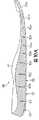
外部層14は内部層15の下部を露出させる複数の切込み27aおよび27bを含む。内部層15を露出させることにより、アッパー20の伸縮特性が選択的に調整される。切込み27aおよび27bが存在しない部分では、層14および15の各々がアッパー20の引き伸ばしに抵抗するように貢献する。しかし切込み27aおよび27bがある部分では、切込み27aおよび27bは外部層14がもっと大幅に延びることを可能にする。そのため切込み27aおよび27bは、アッパー20の特定の部分における伸縮度を選択的に変化させるようにアッパー20内に形成される。更に切込み27aおよび27bは、アッパー20の通気性、柔軟性および全体的な美観(色など)を変更するために利用することができる。 The
図1〜図3において切込み27aおよび27bは、前方領域11と中間領域12とを通って延びる外側部21および内側部22の各部分にわたって分布しているものとして図示されている。一般に切込み27aは線状の形状を有し、靴10の長手方向に延びる方向に向けられている。つまり切込み27aは前方領域11と踵領域13との間に延びる方向に向けられている。ただし母指に対応する前方領域11の一部では、切込み27bは横方向に延設されている。 In FIGS. 1 to 3, the
切込み27aおよび27bの向きは、切込み27aおよび27bによってもたらされる伸縮の方向に影響を与える。一般に切込み27aおよび27bは、切込み27aおよび27bの長手方向に対応する方向における伸縮を増加させない。つまり、特定の切込み27aおよび27bは、その切込み27と平行な方向における伸びを増大させることはない。しかし切込み27aおよび27bは、切込み27aおよび27bの長手方向と垂直な方向におけるアッパー20の伸縮は増大させる。 The orientation of the
切込み27aは長手方向に延びるスリット列を形成するものとして図示されており、隣接する列の切込み27aは互いにずらされている。同様に、切込み27bは横方向に延びるスリット列を形成するものとして図示されており、隣接する列の切込み27bは互いにずらされている。ただし様々な切込み27aおよび27bをその他の配列でアッパー20に追加することもできる。例えば切込み27aおよび27bをずらして列を形成しないようにしてもよく、または切込み27aおよび27bをアッパー20に関してランダムに配置してもよい。 The
切込み27aは上で説明したように、靴10に関して長手方向に向けられている。図6に示したように足をアッパー20の中に入れて、アッパー20、特に外部層14に対して伸ばす力を加えると、切込み27aはアッパー20の周囲長さを増加させるようにアッパー20が延びることを可能にする。すなわち切込み27aは、切込み27aの長手方向に垂直な方向に延びる。切込み27bも同様に延びる。しかし上で説明したように、切込み27bは横方向に向いている。そのため切込み27bは長手方向に延びる。 The
切込み27aおよび27bは、外部層14内への線状の切込みとして図示されている。切込み27aおよび27bの1つまたはそれ以上に対して、大略的に垂直な方向に外部層14に対して伸ばす力が働くと、切込み27aおよび27bの縁が分離して、図6に示すようにとがった端部を有する大略的に楕円形を形成する。切込み27aおよび27bは比較的直線的で短い形態を有するものとして図示されている。しかし本発明の範囲内において、切込み27aおよび27bは直線的または曲線の形状を示すことができ、例えば個々の切込み27aおよび27bの長さを変更することができる。切込み27aおよび27bの形状および長さの違いを利用して、アッパー20の伸びの程度、アッパー20の通気性およびアッパー20の柔軟性と全体の美観とを調整することができる。切込み27aおよび27bの形状および長さを決めるときに考慮すべき要因には、例えばアッパー20内で使用される材料、各材料の固有の伸び率、および伸びが望まれる方向が含まれる。 The
従来のアッパーを形成する材料は互いに縫い合わされることが多く、また接着により材料の同じ範囲の部分を互いに固定することもできる。従来のアッパーの場合と同様に、層14および15は同じ範囲を占める仕方で位置され、互いに接着することができる。しかしいくつかの実施形態では、層14および15は接着されずに分離していてもよい。すなわち層14および15は互いに隣接して位置されるが、縁または応力点以外では互いに固定されていなくてもよく、例えば切込み27aおよび27bの近傍部分では内部層15が外部層14に固定されないようにできる。この構成の利点は、外部層14が内部層15とは独立に伸びて移動できることである。すなわち切込み27aおよび27bは、層14および15の間の接着を通じて大幅には妨げられない外部層14の伸びを可能にする。一般に層14および15は、切込み27aおよび27bを含む部分では、互いに接着その他により固定しなくてもよい。 The materials that form conventional uppers are often stitched together, and the same range of materials can be secured together by gluing. As with conventional uppers, layers 14 and 15 are positioned in a manner that occupies the same area and can adhere to each other. However, in some embodiments, layers 14 and 15 may be separated without being bonded. That is, the
切込み27aおよび27bは外部層14内に形成されるように図示されている。しかし本発明の範囲内で、切込み27aおよび27bはまた層14および15の一方または両方に形成してもよい。例えば切込み27aおよび27bは、外部層14のみ、または外部層14と内部層15との両方に、または内部層15のみに形成してもよい。層14および15の両方が切込み27aおよび27bを含む実施形態では、切込み27aおよび27bの位置を合わせてもまたずらしてもよい。従ってこれまでの説明に基づき、切込み27aおよび27bの形状は本発明の範囲内で大幅に変えることが出来る。 The
切込み27aおよび27bは様々な方法で形成できる。例えばダイス(打ち抜き型)、ナイフまたはかみそりのような切断器具を用いて、切込み27aおよび27bを形成することができる。切断器具のほかに、レーザー装置を使って切込み27aおよび27bを形成し、かつ外部層14を大きな材料要素から除去することができる。従って切込み27aおよび27bは、レーザーを外部層14に照射して、切込み27aおよび27bに対応する部分を外部層14から除去することで形成できる。切込み27aおよび27bの幅はレーザーの幅とほぼ一致する。あるいはまた、レーザーを何度も通過させることでもっと幅の大きい切込み27aおよび27bを形成することもできる。レーザー装置は、出力を調整することにより可変強度のレーザービームを発生する能力を有することができる。出力を調整することに加えて、レーザービームの焦点と、外部層14に対するレーザービームの速度も変えることが出来る。適切なレーザー装置の例としては参照により本明細書に組み入れた、Costinに対する上記特許文献10および上記特許文献11に開示されているように、通常のCO2またはNd:YAGレーザー装置の任意のものである。The
靴のアッパーに組み込まれることの多い合成皮革、皮、ポリマーシートおよびポリマー繊維などの材料の場合、切込み27aおよび27bを形成するためのレーザービームの出力は一般に、例えば0.25から25ワットの範囲である。レーザービームが比較的狭い焦点を有する場合は、レーザービームの単位面積当たりのエネルギー密度が高いことを考慮して、レーザービームの出力を下げればよい。同様に、レーザービームが比較的広い焦点を有する場合は、レーザービームの単位面積当たりのエネルギー密度が低いことを考慮して、レーザービームの出力を上げればよい。レーザービームの焦点および出力を考慮するには、レーザービームの速度の変更を利用できる。合成皮革、皮またはポリマー繊維などの材料に切込み27aおよび27bを形成するには、比較的小さな出力でよいが、高密度のポリマーのような他の材料に同じ深さで切込み27aおよび27bを形成するには、もっと大きな出力を要する可能性がある。そのため、切込み27aおよび27bを形成するためのレーザービームの適切な出力、焦点および/または速度を決定するには多くの要因が考慮される。 For materials such as synthetic leather, leather, polymer sheets and polymer fibers that are often incorporated into the shoe upper, the power of the laser beam to form the
レーザー装置には、外部層14に隣接して移動しながら外部層14内に切込み27aおよび27bを形成するレーザービームの照射装置を含むことができる。すなわち外部層14に対するレーザー装置の相対的な運動により、それぞれの切込み27aおよび27bの形状を制御することができる。あるいは、1つ以上の移動可能または軸回動可能な鏡でレーザービームを反射して、鏡の移動によって外部層14内の切込み27aおよび27bの形状を制御することもできる。 The laser device can include a laser beam irradiation device that forms cuts 27 a and 27 b in the
外部層14内の選択された領域をレーザービームで加熱し、外部層14の選択された部分を焼く(灰化する)ことで切込み27aおよび27bを形成する。外部層14の他の領域が誤って焼かれるのを防ぐために、二酸化炭素や窒素のような非可燃性の流体の存在下で切込み27aおよび27bを形成してもよい。すなわち、レーザービームが切込み27aおよび27bを形成する際に非可燃性の流体を放出するようにレーザー装置を構成してもよい。
一旦外部層14内に切込み27aおよび27bが形成されると、アッパー20内の空洞に足の一般的な形状を与える靴型の周囲でアッパー20の各要素が結び付けられる。すなわち、前方領域11から踵の領域13にかけて延設されたアッパー20の外側部21と内側部22とを形成する靴型の周囲で各要素が互いに結び付けられる。加えて、例えばベロ23と靴紐部26とを含むように甲部分が形成され、踵領域13内に足首の開口部25が形成される。永続的な内部ライニング24も外側部21および内側部22の下端に固定され、永続的な内部ライニング24は靴型の下に延びてアッパー20内の空洞の下側表面を形成する。次に靴底構造30の一部分が永続的な内部ライニング24を含むアッパー20の下側部分に恒久的に固定される。アッパー20と靴底構造30との結合には、接着剤、縫合または接着剤と縫合との組み合わせを利用できる。このようにして、概略従来の工程によってアッパー20が靴底構造30に固定される。 Once the
靴底構造30はインソール31(以下で詳細に説明する)、ミッドソール32、およびアウトソール33を含む。インソール30はアッパー20の内部に位置し、足の裏側(下側)表面に接触するために永続的な内部ライニング24の上側表面に隣接して配置され、靴10の快適性を向上させる。ミッドソール32は永続的な内部ライニング24を含むアッパー20の下側部分に固定され、使用中は足の下に延びるように位置する。ミッドソール32は例えばウォーキングまたはランニング中の地面反力を減衰させてエネルギーを吸収する(クッション作用を与える)など様々な目的を果たす。ミッドソール32に適した材料は、エチルビニルアセテートまたはポリウレタン発泡体など、靴のミッドソールに使用される従来のポリマー発泡材料のいずれでもよい。ミッドソール32はまた、Bayer AG社によってBAYFLEXという商標名で製造されている比重約0.22の比較的軽量のポリウレタン発泡体で形成してもよい。アウトソール33はミッドソール32の下側表面に固定されて耐摩耗性を与えるが、アウトソール33はミッドソール32内に埋め込まれていてもよい。アウトソール33はミッドソール32の下側表面全体にわたって延設してもよいが、図に示された特定の実施形態においてはアウトソール33は踵領域13の中に位置する。アウトソール33に適した材料は、カーボンブラック・ゴム組成物など、靴のアウトソールに使用される従来のゴム系材料のいずれをも含む。 The
通常の靴のミッドソールは足の長さにわたって延びる発泡ポリマー製の単一構造であり、足の自然な動きを阻害する剛性すなわち非柔軟性を有することがある。通常の靴のミッドソールとは異なり、ミッドソール32は比較的高い柔軟性と分節結合とを与える分節構造を有する。ミッドソール32の柔軟な構造は(アッパー20の構造と組み合わされて)、ランニングその他の運動の間の足の自然な動きを補完するように構成され、裸足で走っているような感覚を与えることができる。しかし裸足で走る場合と違い、ミッドソール32は地面反力を減衰させてエネルギーを吸収し、足に対するクッション作用を与えて足への全体的なストレスを軽減する。 A typical shoe midsole is a single structure made of a foamed polymer that extends over the length of the foot and may have stiffness or inflexibility that hinders the natural movement of the foot. Unlike a normal shoe midsole, the
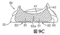
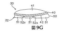
ミッドソール32は連結部分40とサイプ(溝)部50を含む。連結部分40は上側表面41およびその反対側の下側表面42を形成する。上側表面41はアッパー20に隣接して配置され、アッパー20に直接固定することができ、それによって足を支える。そのため上側表面41は、足の自然な解剖学的な形状に適合するように形成される。従って踵領域13内に配置された上側表面41の部分は、前方領域11内の上側表面41の部分よりも大きな高度を有することができる。更に上側表面41は中間領域12内にアーチ支持部を形成することができ、上側表面41の周辺領域は一般に高くして、足を受け入れて落ち着かせるためのくぼみを与える。別の実施形態では、上側表面41は輪郭を付けない形状を有することができる。 The
上側表面41と下側表面42との間に延びる寸法として規定される連結部分40の厚みは、ミッドソール32の長手方向に沿って変化することができる。図9Aでは厚みは寸法43a〜43cとして図示されている。前方領域11内に規定される寸法43aは例えば約3mmであり、1mm〜5mmの範囲内であってもよい。中間領域12内に規定される寸法43bは例えば約8mmであり、1mm〜11mmの範囲内であってよい。同様に踵領域13内に規定される寸法43cは例えば約6mmであり、1mm〜10mmの範囲内であってよい。従って連結部分40の厚みは、前方領域11および踵領域13から中間領域12に向かう各方向に増加することができる。しかし当業者であれば、様々な厚み寸法および変形が連結部分40に対して適切であることを理解するであろう。 The thickness of the connecting
比較的小さな厚みを示す連結部分40の部分は一般に、より大きな厚みを示す連結部40の部分よりも高い柔軟性を有する。従って連結部40の部分の厚みの変化を利用して、特定部分における靴底構造30の柔軟性を変化させることができる。例えば厚みの小さな連結部分40を形成することにより、前方領域11は比較的高い柔軟性を有するように構成できる。厚みの大きな連結部分40を形成することにより、中間領域12に比較的低い柔軟性を与えることができる。同様に、前方領域11と中間領域12との中間の厚みを有する連結部分40を形成することにより、踵領域13に中間の柔軟性を与えることができる。 The portion of the connecting
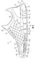
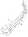
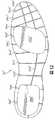
サイプ部50は複数のサイプ(溝)52a〜52lによって分離される複数の個別の分離した靴底要素51を形成する。靴底要素51は、連結部分40から下向きに延びるミッドソール30の不連続な部分である。更に靴底要素51は連結部分40に固定されており、また連結部分40と一体に形成することもできる。各靴底要素51の形状は、サイプ52a〜52lの位置によって決定される。図8に示すように、サイプ52aおよび52bは靴底構造30の長手方向に沿って延び、またサイプ52c〜52lは大略的に横方向に延びる。サイプ52a〜52lをこのように配置することで、大略的に正方形、長方形または台形をなす靴底要素51の大多数が形成される。最も後方の靴底要素51は、踵領域13内の靴底構造30の曲面形状のために、円周の4分の1の形状を有する。 The
下側表面40とミッドソール32の下側表面との間に延びる寸法として規定されるサイプ部50の厚みは、ミッドソール32の長手方向に沿って変化させてもよい。この厚みは、図9Aにおいて寸法53aおよび53cとして図示されている。前方領域11内で規定される寸法53aは例えば約7mmで、3mm〜12mmの範囲内であってもよい。同様に踵領域13内で規定される寸法53cは例えば約12mmであり、8mm〜20mmの範囲内であってもよい。従ってサイプ部50の厚みは、前方領域11から踵領域13に延びる方向に増加することができる。しかし当業者であれば、様々な厚み寸法および変形がサイプ部50に対して適切であることを理解するであろう。 The thickness of the
寸法43aおよび53aの組み合わせにより、前方領域11内でのミッドソール32の全体の厚みが形成される。同様に、寸法43cおよび53cの組み合わせにより、踵領域13内でのミッドソール32の全体の厚みが形成される。靴10の構成は男性用および女性用の靴でほぼ同じであるが、実験によれば男性は一般に女性よりも全体としての厚みの違いが小さい方を好むことが分かった。従って、男性用に設計された靴10の前方領域11内での全体の厚みを10mmとし、踵領域13内での全体の厚みを18mmとして、8mmの差をつけることができる。しかし女性用に設計された靴10では、前方領域11内での全体の厚みは同じく10mmであるが、踵領域13内での全体の厚みを22mmとして、12mmの差をつけることができる。従って女性用に設計された靴10では、前方領域11と踵領域13との間の全体の厚みの差は男性用の厚みの差よりも大きくできる。靴10に大きな厚みの差を与えるには、例えば踵領域13内に位置される靴底要素51の厚みを大きくすればよい。 The total thickness of the
上で述べたように、靴底要素51の各々の形状は、上に向かってミッドソール32内に延び、かつ各靴底要素51の間で延びる切れ目または空間であるサイプ52a〜52lの位置によって決定される。サイプ52a〜52lはまた、ミッドソール32内の分節構造を形成することにより、靴底構造30の柔軟性を高める。通常の靴のミッドソールは発泡ポリマーからなる一体の(まとまった)要素であるが、サイプ52a〜52lは靴底構造30内に屈曲線を形成し、したがってミッドソール32内の曲がりの方向に影響を与える。サイプ52a〜52lの影響で靴底構造30が曲がりまたは分節結合する仕方を、図7に図式的に示す。 As mentioned above, the shape of each of the
靴底構造30の横方向の柔軟性(すなわち外側部と内側部との間に延びる方向での柔軟性)は、サイプ52aおよび52bによって与えられる。サイプ52aは3つの領域11〜13の全てを通って長手方向に延びる。サイプ52aは直線つまり線形の形状を有することができるが、サイプ52aは一般にカーブした、またはs字形状を有するものとして図示されている。前方領域11と中間領域12とでは、サイプ52aは靴底構造30の外側部から内側に向かって間隔を開けて配置され、またサイプ52aは踵領域13内で中央に位置する。前方領域11内および中間領域12の一部にのみ位置されるサイプ52bは中央に位置され、かつ一般にサイプ52aと平行な方向に延びる。一般にサイプ52aおよび52bの深さは、サイプ52aおよび52bが前方領域11から踵領域13に向かって延びるに従って大きくなる。 The lateral flexibility of the sole structure 30 (ie, the flexibility in the direction extending between the outer and inner portions) is provided by
靴底構造30の長手方向の柔軟性(すなわち領域11と領域13との間に延びる方向における柔軟性)は、サイプ52c〜52lによって与えられる。サイプ52c〜52fは前方領域11内に位置しており、サイプ52gは大略的に前方領域11と中間領域12との間の界面に沿って延び、サイプ52hおよび52iは中間領域12内に位置し、サイプ52jは大略的に中間領域12と踵領域13との間の界面に沿って延び、そしてサイプ52kおよび52lは踵領域13内に位置する。図8を参照して、サイプ52i〜52lはほぼ平行であり、内側部から外側部に向かう方向に延びている。サイプ52c〜52hもほぼ平行であり、内側部から外側部に向かう方向に延びる形状を有するが、サイプ52c〜52hはサイプ52i〜52lに関して多少角度をなしている。 The flexibility in the longitudinal direction of the sole structure 30 (that is, the flexibility in the direction extending between the
サイプ52a〜52lの位置と向きとは、ランニングのサイクルの間の足の自然な動きを補完するように選択される。一般に、ランニング中の足の動きは次のように進行する。最初に踵が地面に当たり、それに続いて親指の付け根が地面に当たる。踵が地面を離れるときに足は前方に向かってローリング運動を行ってつま先が接地し、最後に足全体が地面を離れて次のサイクルを開始する。足が地面に接している間に、足は通常外側すなわち外側部から内側すなわち内側部に向かってローリングする、回内動作と呼ばれるプロセスが行なわれる。すなわち通常は、踵の外側が最初に当たり、足の内側のつま先が最後に地面から離れる。サイプ52c〜52lは、足が中立的な接地位置に止まることを保証すると同時に、足が地面に接した状態で中立的な前方へのローリングを行なう運動を補完する。サイプ52aおよび52bは、ランニングのサイクル中に足が自然に回内動作をすることができるように、横方向の柔軟性を与える。同様に、サイプ52c〜52hの角度をつけた構成が上で述べたように、足の自然な動きを更に強める柔軟性を更に加える。 The position and orientation of the
サイプ52eは、前方領域11内での逆方向の屈曲ができるように、他のサイプ52a〜52dおよびサイプ52f〜52lよりも大きな幅を有する。一般に、サイプ52a〜52lは図7に示すように靴底構造30の上向きの曲がりを可能にする。ランニングサイクルの終わりに(つまりつま先が地面を離れる前に)更に地面捕捉力を与えるために、人は足底の屈曲で足指を曲げるかその他の仕方でつま先を地面に押し付ける可能性がある。サイプ52eが広くなっていることにより足底の屈曲が容易になり、それによりランニング中の足の自然な動きが促進される。すなわち、サイプ52eはミッドソール32内に逆屈曲溝を形成している。実験の解析によれば、男性は前方領域内で足底の屈曲を起こす傾向が女性よりも低いことが分かっている。女性における足底の屈曲を起こす高い傾向を助けるために、女性用に設計された靴10には更に幅の広いサイプ52eを持たせるか、またはサイプ52dの幅も大きくすることができる。従って女性用に設計された靴10では、図10Aの断面図で示されるようにサイプ52dおよびサイプ52eの両方の幅を広くすることができる。 The
アウトソール33は選択された靴底要素51の下側表面に固定された複数のアウトソール要素を含み、また選択された靴底要素51の下側表面にアウトソール要素を受けるためのくぼみが形成されている。図に示されているように、アウトソール33は踵領域13に制限されている。しかしある実施形態では、各靴底要素51を1つのアウトソール要素に関連付けるか、またはアウトソール33をミッドソール32の下側表面全体にわたって延設することもできる。 The
ミッドソール32を形成するには複数の製造方法を好適に使用できる。例えばミッドソール32を一体の要素として形成し、その後サイプ52a〜52lを切込み工程によって形成してもよい。ミッドソール32を成型し、その成型過程でサイプ52a〜52lが形成されるようにしてもよい。ミッドソール32に対する適切な成型方法には例えば、射出成型、注入法、圧縮成型などがある。それぞれの成型方法において、ミッドソール32の一般的な形状を有する金型の中に発泡ポリマー樹脂が注入される。金型はサイプ52a〜52lの位置に対応する薄い刃を含む。ポリマー樹脂は金型内および各々の刃の周囲に配置される。材料が硬化するとミッドソール32は金型から取り出され、成型工程の間にサイプ52a〜52lが形成される。サイプ52a〜52lの幅は金型内の刃の厚みを調整することにより制御される。そのため、例えばサイプ52eの逆屈曲特性はサイプ52eを形成する刃の厚みによって調整でき、また他のサイプ52a〜52dおよびサイプ52f〜52lが逆方向に屈曲する程度は対応する刃の厚みにより制御できる。サイプ52a〜52dおよびサイプ52f〜52lを形成する刃に対する適切な厚みの範囲は0.2mm〜0.3mmであり、これにより比較的小さな逆屈曲が得られる。同様に、サイプ52eを形成する金型の部分に対する適切な幅の範囲は3mm〜5mmであり、これによりもっと大きな逆屈曲が得られる。 A plurality of manufacturing methods can be suitably used to form the
アッパー20と靴底構造30とは互いに協調して屈曲し、伸び、またはその他の動きを行なって裸足で走るような自然な感覚を与えるような構造を有する。すなわちアッパー20と靴底構造30とは、ランニングその他の運動中の足の自然な動きを補完するように構成されている。上で述べたように、外部層14は複数の切込み27aおよび27bを含み、これらが特定の部分および特定の方向におけるアッパー20の伸縮特性を高める。切込み27aは例えばアッパー20の周囲長の伸びを許すような方向に向けられ、切込み27bは母指の動きと足裏の屈曲を容易にすることができる。切込み27aおよび27bはまた、一般により柔軟性が高い構造をアッパー20に与え、これが靴底構造30の柔軟性を補完する。上で述べたように、ミッドソール32は靴底構造30の屈曲特性を高める複数のサイプ52a〜52lを含む。サイプ52a〜52lの位置、向きおよび深さは、選択された部位および方向において特定の程度の柔軟性を与えるように選択される。すなわちサイプ52a〜52lは、使用者に裸足で走るような自然な感覚を与えるために利用できる。しかし裸足で走るのとは異なり、靴底構造30が地面からの反力を減衰させてエネルギーを吸収し、足に対するクッション作用を与えて足への全体的なストレスを軽減する。 The upper 20 and the shoe
上で述べたように、通常の靴底構造は比較的剛性の高い、つまり曲がりにくい構造を有し、それが足の自然な動きを阻害する可能性がある。例えばランニングサイクル中に踵が地面から離れる段階で、足は屈曲しようとするかもしれない。曲がりにくいミッドソール構造と従来の踵カウンターとの組み合わせは、足の屈曲に抵抗するように働く。それに対して靴10は足と共に屈曲し、また従来の踵カウンターを組み込まない構成とすることができる。 As mentioned above, a normal sole structure has a relatively rigid structure, that is, a structure that is difficult to bend, which may hinder the natural movement of the foot. For example, the foot may try to bend when the heel leaves the ground during the running cycle. The combination of a midsole structure that is difficult to bend and a conventional heel counter works to resist foot flexion. On the other hand, the
靴底構造30全体としての柔軟性は、インソール31の構造により向上させることができる。図11を参照して、インソール31の下側表面は一般にサイプ52a〜52lの位置および形状に対応する複数の屈曲線34a〜34lを有するとして図示されている。より具体的には、屈曲線34aはインソール31のほぼ全長にわたって長手方向に延びて、大略的にサイプ52aの位置に対応する。屈曲線34bはインソール31の長さの一部のみにわたって長手方向に延びて、ほぼサイプ52bの位置に対応する。同様に、屈曲線34c〜34lはインソール31の内側部から外側部へ横方向に延び、かつほぼサイプ52c〜52lの位置に対応する。この構成により、靴底構造30の柔軟性が高まり、またサイプ52a〜52lがもたらす分節構造が強められる。同様の構造を示す図12において、インソール31’は複数の屈曲線34a’〜34l’と、圧縮可能な発泡ポリマーで形成された2つのクッションパッド35a’および35b’を含む。 The flexibility of the
図面に示された靴10の構造および形状について詳細に説明してきた。本発明の範囲から逸脱することなく、靴10に様々な変更を行なうことができる。例えば切込み27aおよび27bを、層14および15のいずれか、または層14および15の両方に形成することができる。切込み27aおよび27bはまた、異なる向きまたは位置に形成して異なる伸縮特性を与え、またはアッパー20内に従来の踵カウンターを組み込んでもよい。靴底構造30に関して、連結部分40の厚みまたはミッドソール32全体の厚みは大幅に変化させることができる。更にまたサイプ52a〜52lの深さ、向きおよび位置を変更してもよい。 The structure and shape of the
本発明の様々な実施形態を、上の説明と添付図面とで開示した。しかしこの開示の目的は、本発明の範囲を制限することではなく、本発明に関する様々な特徴および概念の例を示すことである。当業者であれば、添付の特許請求の範囲によって規定された本発明の範囲から逸脱することなく、上で述べた実施形態に対して多くの変形や変更を行なえること認識するであろう。 Various embodiments of the present invention have been disclosed in the above description and accompanying drawings. However, the purpose of this disclosure is not to limit the scope of the invention, but to illustrate examples of various features and concepts relating to the invention. Those skilled in the art will recognize that many variations and modifications may be made to the above-described embodiments without departing from the scope of the invention as defined by the appended claims.
Claims (26)
Translated fromJapanese当該履物に関して長手方向に向けられた第一のサイプであって、前記第一のサイプが前記履物底構造の全長にわたって延び、前記第一のサイプが当該履物の少なくとも前方領域で前記履物底構造において、右足における右側の部分に対応する部分および/または左足における左側の部分に対応する部分である外側部から内側に向かって間隔をあけて配置され、かつ前記第一のサイプが当該履物の踵領域内において前記履物底構造の前記外側部と、右足における左側の部分に対応する部分および/または左足における右側の部分に対応する部分である内側部との間のほぼ中央に位置する第一のサイプと、
長手方向に延びる第二のサイプであって、前記履物底構造の長さの一部のみを通って延びる第二のサイプと、
前記履物底構造の前記内側部から前記外側部へ横方向に延びる複数の第三のサイプとを含む履物。An footwear having an upper and a footwear bottom structure fixed to the upper, the footwear bottom structure comprising a plurality of discontinuous footwear bottom elements extending downwardly from a connecting portion, the footwear bottom elements beingoutward Are exposed to and separated by a plurality of sipes extending upwardly into the footwear bottom structure, wherein the plurality of sipes are:
A first sipe oriented longitudinally with respect to the footwear, wherein the first sipe extends over the entire length of the footwear bottom structure, the first sipe in the footwear bottom structure at least in a forward region of the footwear. A portion corresponding to the right portion of the right foot and / or a portion corresponding to the left portion of the left foot, spaced from the outside to the inside, and the first sipe is the heel region of the footwear A first sipe located approximately in the middle between the outer part of the footwear structure and the inner part which is the part corresponding to the left part of the right foot and / or the right part of the left foot When,
A second sipe extending longitudinally, the second sipe extending only through a portion of the length of the footwear bottom structure;
And a plurality of third sipes extending laterally from the inner portion to the outer portion of the footwear bottom structure.
前記アッパーの外部の少なくとも一部を形成する外部層であって、前記外部層を貫通して延びる複数の切込みを含む外部層と、
前記外部層の内側表面の少なくとも一部に隣接して位置する内部層であって、前記切込みの少なくとも一部を通して露出されている内部層とを含む、請求項1記載の履物。The upper is an outer layer forming at least a part of the outside of the upper, and includes an outer layer including a plurality of cuts extending through the outer layer;
The footwear of claim 1, comprising an inner layer located adjacent to at least a portion of the inner surface of the outer layer, the inner layer being exposed through at least a portion of the incision.
連結部分と、前記連結部分から延びる複数の不連続な履物底要素とを含む履物底構造であって、前記履物底要素が前記履物底構造内に延びる複数のサイプによって分離されている履物の履物底構造を成型する工程と、
前記履物底構造を、前方領域で第一の厚みを有し、踵領域で第二の厚みを有する構造に形成する工程と、
前記第一の厚みと前記第二の厚みとの差が、前記男性用バージョンの履物における対応する差よりも大きくなるように女性用バージョンの履物を形成する工程とを含む方法。A method of manufacturing footwear havinga female versionintended for women anda male versionintended for men,
A connecting portion, a sole structure includinga plurality of discrete sole elements extending from the connecting portion, footwear footwear being separated by a plurality of sipes which the sole element extends into the footwear sole structure Forming the bottom structure;
Forming the footwear bottom structure into a structure having a first thickness in the front region and a second thickness in the heel region;
Forming a female versionof the footwear such that a difference between the first thickness and the second thickness is greater than a corresponding difference in the male versionof the footwear .
前記アッパーの外部の少なくとも一部を形成する外部層であって、前記外部層を貫通して延びる複数の切込みを含み、前記切込みがレーザーエッチング工程で形成された外部層と、
前記外部層の内側表面の少なくとも一部に隣接して位置する内部層であって、前記内部層は、前記切込みの近傍にある部分において前記外部層に固定されておらず、また前記内部層は、前記切込みの少なくとも一部を通して露出されている内部層とを含む履物。An footwear having an upper and a footwear bottom structure, wherein the upper is
An outer layer that forms at least a portion of the exterior of the upper, and includes a plurality of cuts extending through the outer layer, wherein the cut is formed by a laser etching process; and
An inner layer located adjacent to at least a portion of the inner surface of the outer layer, the inner layer not being secured to the outer layer in a portion near the notch, and the inner layer is And an inner layer exposed through at least a portion of the cut.
Applications Claiming Priority (2)
| Application Number | Priority Date | Filing Date | Title |
|---|---|---|---|
| US10/681,321US6990755B2 (en) | 2003-10-09 | 2003-10-09 | Article of footwear with a stretchable upper and an articulated sole structure |
| PCT/US2004/033111WO2005034670A2 (en) | 2003-10-09 | 2004-10-08 | Article of footwear with a stretchable upper and an articulated sole structure |
Related Child Applications (1)
| Application Number | Title | Priority Date | Filing Date |
|---|---|---|---|
| JP2009176817ADivisionJP5102256B2 (en) | 2003-10-09 | 2009-07-29 | Footwear having a stretchable upper and a segmented footwear bottom structure |
Publications (2)
| Publication Number | Publication Date |
|---|---|
| JP2007508055A JP2007508055A (en) | 2007-04-05 |
| JP4620677B2true JP4620677B2 (en) | 2011-01-26 |
Family
ID=34422261
Family Applications (6)
| Application Number | Title | Priority Date | Filing Date |
|---|---|---|---|
| JP2006534338AExpired - LifetimeJP4620677B2 (en) | 2003-10-09 | 2004-10-08 | Footwear having a stretchable upper and a segmented footwear bottom structure |
| JP2009176817AExpired - LifetimeJP5102256B2 (en) | 2003-10-09 | 2009-07-29 | Footwear having a stretchable upper and a segmented footwear bottom structure |
| JP2011091427AExpired - LifetimeJP5209079B2 (en) | 2003-10-09 | 2011-04-15 | Footwear having an upper and a footwear bottom structure |
| JP2011091419AExpired - LifetimeJP5314077B2 (en) | 2003-10-09 | 2011-04-15 | Footwear having a segmented footwear structure |
| JP2011091431AExpired - LifetimeJP5209081B2 (en) | 2003-10-09 | 2011-04-15 | Footwear having an upper and a footwear bottom structure |
| JP2011091429AExpired - LifetimeJP5209080B2 (en) | 2003-10-09 | 2011-04-15 | Footwear having a stretchable upper and a footwear bottom structure |
Family Applications After (5)
| Application Number | Title | Priority Date | Filing Date |
|---|---|---|---|
| JP2009176817AExpired - LifetimeJP5102256B2 (en) | 2003-10-09 | 2009-07-29 | Footwear having a stretchable upper and a segmented footwear bottom structure |
| JP2011091427AExpired - LifetimeJP5209079B2 (en) | 2003-10-09 | 2011-04-15 | Footwear having an upper and a footwear bottom structure |
| JP2011091419AExpired - LifetimeJP5314077B2 (en) | 2003-10-09 | 2011-04-15 | Footwear having a segmented footwear structure |
| JP2011091431AExpired - LifetimeJP5209081B2 (en) | 2003-10-09 | 2011-04-15 | Footwear having an upper and a footwear bottom structure |
| JP2011091429AExpired - LifetimeJP5209080B2 (en) | 2003-10-09 | 2011-04-15 | Footwear having a stretchable upper and a footwear bottom structure |
Country Status (12)
| Country | Link |
|---|---|
| US (3) | US6990755B2 (en) |
| EP (7) | EP2298103B1 (en) |
| JP (6) | JP4620677B2 (en) |
| CN (4) | CN101263943A (en) |
| AT (2) | ATE479348T1 (en) |
| AU (5) | AU2004279433B2 (en) |
| BR (2) | BRPI0414955A (en) |
| CA (1) | CA2540975C (en) |
| DE (2) | DE602004032560D1 (en) |
| TW (4) | TWI369959B (en) |
| WO (1) | WO2005034670A2 (en) |
| ZA (1) | ZA200602761B (en) |
Cited By (2)
| Publication number | Priority date | Publication date | Assignee | Title |
|---|---|---|---|---|
| KR20190079151A (en)* | 2017-12-27 | 2019-07-05 | 웰바이오텍 주식회사 | Shoe outsole with free deformation |
| US10709204B2 (en) | 2013-09-30 | 2020-07-14 | Mizuno Corporation | Shoes |
Families Citing this family (235)
| Publication number | Priority date | Publication date | Assignee | Title |
|---|---|---|---|---|
| US7634529B2 (en) | 1996-11-29 | 2009-12-15 | Ellis Iii Frampton E | Personal and server computers having microchips with multiple processing units and internal firewalls |
| US7752775B2 (en) | 2000-03-10 | 2010-07-13 | Lyden Robert M | Footwear with removable lasting board and cleats |
| US7065820B2 (en)* | 2003-06-30 | 2006-06-27 | Nike, Inc. | Article and method for laser-etching stratified materials |
| US7424783B2 (en)* | 2003-06-30 | 2008-09-16 | Nike, Inc. | Article of apparel incorporating a stratified material |
| US8303885B2 (en)* | 2003-10-09 | 2012-11-06 | Nike, Inc. | Article of footwear with a stretchable upper and an articulated sole structure |
| US7290357B2 (en) | 2003-10-09 | 2007-11-06 | Nike, Inc. | Article of footwear with an articulated sole structure |
| US6990755B2 (en)* | 2003-10-09 | 2006-01-31 | Nike, Inc. | Article of footwear with a stretchable upper and an articulated sole structure |
| US8146272B2 (en)* | 2008-05-30 | 2012-04-03 | Nike, Inc. | Outsole having grooves forming discrete lugs |
| EP1824351B1 (en)* | 2004-08-18 | 2012-08-01 | Fox Head, Inc. | Footwear with bridged decoupling |
| US12290134B2 (en) | 2004-11-22 | 2025-05-06 | Frampton E. Ellis | Footwear or orthotic sole with microprocessor control of a structural or support element with magnetorheological fluid |
| CA2630817C (en) | 2004-11-22 | 2016-10-18 | Frampton E. Ellis | Devices with internal flexibility sipes, including siped chambers for footwear |
| US8256147B2 (en) | 2004-11-22 | 2012-09-04 | Frampton E. Eliis | Devices with internal flexibility sipes, including siped chambers for footwear |
| US8291618B2 (en)* | 2004-11-22 | 2012-10-23 | Frampton E. Ellis | Devices with internal flexibility sipes, including siped chambers for footwear |
| US7310894B1 (en)* | 2005-05-12 | 2007-12-25 | Schwarzman John L | Footwear for use in shower |
| USD541015S1 (en) | 2005-05-27 | 2007-04-24 | Reebok International Ltd. | Shoe sidewall |
| US7540097B2 (en)* | 2005-06-20 | 2009-06-02 | Nike, Inc. | Article of footwear having an upper with a matrix layer |
| US20070023955A1 (en)* | 2005-07-27 | 2007-02-01 | Danny Ho | Footware cushioning method |
| US7464489B2 (en)* | 2005-07-27 | 2008-12-16 | Aci International | Footwear cushioning device |
| GB0522216D0 (en)* | 2005-11-01 | 2005-12-07 | Connor Michael J O | Footwear |
| US7555851B2 (en)* | 2006-01-24 | 2009-07-07 | Nike, Inc. | Article of footwear having a fluid-filled chamber with flexion zones |
| US7650707B2 (en)* | 2006-02-24 | 2010-01-26 | Nike, Inc. | Flexible and/or laterally stable foot-support structures and products containing such support structures |
| US7707748B2 (en)* | 2006-02-24 | 2010-05-04 | Nike, Inc. | Flexible foot-support structures and products containing such support structures |
| GB0604728D0 (en) | 2006-03-09 | 2006-04-19 | Clark C & J Int Ltd | Sole unit for an article of footwear |
| US20070214682A1 (en)* | 2006-03-17 | 2007-09-20 | Smotrycz Zenon O | Ventilated shoe sole construction with improved medical support |
| JP4900781B2 (en)* | 2006-03-23 | 2012-03-21 | 秀夫 渡辺 | Finger reinforcement |
| ES1062588Y (en)* | 2006-03-31 | 2006-10-01 | Nordika S S L | SOLE FOR FOOTWEAR |
| JP4919479B2 (en)* | 2006-07-31 | 2012-04-18 | ピジョン株式会社 | Elderly shoes |
| JP4153002B2 (en)* | 2006-08-30 | 2008-09-17 | 美津濃株式会社 | Middle foot structure of shoe sole assembly |
| US9089184B1 (en) | 2006-09-11 | 2015-07-28 | Mary Kiser | Sandal with formed hinge and method of use |
| US7694435B1 (en)* | 2006-09-11 | 2010-04-13 | Mary Kiser | Foldable flip flop with formed hinge |
| US9402438B2 (en) | 2006-09-27 | 2016-08-02 | Rush University Medical Center | Joint load reducing footwear |
| US7954261B2 (en)* | 2006-09-27 | 2011-06-07 | Rush University Medical Center | Joint load reducing footwear |
| USD560336S1 (en)* | 2006-10-25 | 2008-01-29 | Wiesner Products Inc. | Sole and mid-sole for footwear |
| US10238170B2 (en) | 2007-02-28 | 2019-03-26 | Nike, Inc. | Article of footwear having a polygon lug sole pattern |
| WO2008106427A2 (en)* | 2007-02-28 | 2008-09-04 | Nike, Inc. | Article of footwear having a polygon lug sole pattern |
| US7946058B2 (en)* | 2007-03-21 | 2011-05-24 | Nike, Inc. | Article of footwear having a sole structure with an articulated midsole and outsole |
| USD568593S1 (en)* | 2007-04-23 | 2008-05-13 | C2 Corporation | Sole |
| USD565285S1 (en)* | 2007-05-17 | 2008-04-01 | Wolverine World Wide, Inc. | Footwear sole |
| WO2008155785A1 (en)* | 2007-06-19 | 2008-12-24 | Pirelli & C. S.P.A. | A shoe with flexible structure |
| US7941941B2 (en)* | 2007-07-13 | 2011-05-17 | Nike, Inc. | Article of footwear incorporating foam-filled elements and methods for manufacturing the foam-filled elements |
| US9788603B2 (en) | 2007-10-23 | 2017-10-17 | Nike, Inc. | Articles and methods of manufacture of articles |
| US9795181B2 (en)* | 2007-10-23 | 2017-10-24 | Nike, Inc. | Articles and methods of manufacture of articles |
| US9572402B2 (en)* | 2007-10-23 | 2017-02-21 | Nike, Inc. | Articles and methods of manufacturing articles |
| WO2009058720A1 (en)* | 2007-10-29 | 2009-05-07 | The Keds Corporation | Articles of footwear |
| US8125796B2 (en) | 2007-11-21 | 2012-02-28 | Frampton E. Ellis | Devices with faraday cages and internal flexibility sipes |
| GB2455358A (en)* | 2007-12-07 | 2009-06-10 | Siena Black Ltd | Foldable footwear |
| US9856415B1 (en) | 2007-12-11 | 2018-01-02 | Superior Silica Sands, LLC | Hydraulic fracture composition and method |
| US10920494B2 (en) | 2007-12-11 | 2021-02-16 | Aquasmart Enterprises, Llc | Hydraulic fracture composition and method |
| US9057014B2 (en) | 2007-12-11 | 2015-06-16 | Aquasmart Enterprises, Llc | Hydraulic fracture composition and method |
| US20170137703A1 (en) | 2007-12-11 | 2017-05-18 | Superior Silica Sands, LLC | Hydraulic fracture composition and method |
| US8562549B2 (en)* | 2008-03-04 | 2013-10-22 | Covidien Lp | Compression device having an inflatable member including a frame member |
| US20090227918A1 (en)* | 2008-03-04 | 2009-09-10 | Tyco Healthcare Group Lp | Compression device having an inflatable member with a pocket for receiving a counterforce component |
| US8192380B2 (en)* | 2008-03-04 | 2012-06-05 | Tyco Healthcare Group Lp | Compression device with sole |
| US20090227921A1 (en)* | 2008-03-04 | 2009-09-10 | Tyco Healthcare Group Lp | Bendable sole for compression foot cuff |
| US20090227920A1 (en)* | 2008-03-04 | 2009-09-10 | Tyco Healthcare Group Lp | Sole with anchor for compression foot cuff |
| USD584887S1 (en)* | 2008-03-17 | 2009-01-20 | Deckers Outdoor Corporation | Footwear outsole |
| US8631590B2 (en) | 2008-06-04 | 2014-01-21 | Nike, Inc. | Article of footwear for soccer |
| US20090313856A1 (en)* | 2008-06-20 | 2009-12-24 | Arizumi James K | Flexible sole for an article of footwear |
| USD586093S1 (en)* | 2008-09-11 | 2009-02-10 | Nike, Inc. | Shoe outsole |
| USD584493S1 (en)* | 2008-09-11 | 2009-01-13 | Nike, Inc. | Shoe outsole |
| CN102215710B (en) | 2008-10-10 | 2014-01-22 | 耐克国际有限公司 | Article of footwear with a midsole structure |
| DE102008064493A1 (en)* | 2008-12-23 | 2010-06-24 | Adidas International Marketing B.V. | sole |
| US8099880B2 (en)* | 2009-01-05 | 2012-01-24 | Under Armour, Inc. | Athletic shoe with cushion structures |
| US8870876B2 (en) | 2009-02-13 | 2014-10-28 | Tarsus Medical Inc. | Methods and devices for treating hallux valgus |
| USD597289S1 (en)* | 2009-03-27 | 2009-08-04 | Nike, Inc. | Shoe outsole |
| US8393028B2 (en) | 2009-04-23 | 2013-03-12 | Nike, Inc. | Method of manufacturing footwear having sipes |
| US8104197B2 (en) | 2009-04-27 | 2012-01-31 | Nike, Inc. | Article of footwear with vertical grooves |
| US8186079B2 (en)* | 2009-05-06 | 2012-05-29 | Nike, Inc. | Article of footwear with sipes |
| CN101919606A (en)* | 2009-06-12 | 2010-12-22 | 皮雷利&C.有限公司 | Shoe and sole |
| US8333021B2 (en)* | 2009-06-26 | 2012-12-18 | Nike, Inc. | Article of footwear with a collapsible structure |
| US8277459B2 (en) | 2009-09-25 | 2012-10-02 | Tarsus Medical Inc. | Methods and devices for treating a structural bone and joint deformity |
| US8453354B2 (en) | 2009-10-01 | 2013-06-04 | Nike, Inc. | Rigid cantilevered stud |
| US8572866B2 (en) | 2009-10-21 | 2013-11-05 | Nike, Inc. | Shoe with composite upper and foam element and method of making same |
| US8429835B2 (en)* | 2009-10-21 | 2013-04-30 | Nike, Inc. | Composite shoe upper and method of making same |
| JP5448774B2 (en)* | 2009-12-14 | 2014-03-19 | ミタニコーポレーション株式会社 | safety shoes |
| US8677655B2 (en)* | 2010-01-19 | 2014-03-25 | Ming Te Chen | Shoe with anti-slip device |
| US8652141B2 (en) | 2010-01-21 | 2014-02-18 | Tarsus Medical Inc. | Methods and devices for treating hallux valgus |
| US8505220B2 (en) | 2010-03-04 | 2013-08-13 | Nike, Inc. | Flex groove sole assembly with biasing structure |
| US8782924B2 (en) | 2010-05-11 | 2014-07-22 | Nike, Inc. | Article of footwear having a sole structure with a framework-chamber arrangement |
| US8782928B2 (en) | 2010-05-25 | 2014-07-22 | Nike, Inc. | Footwear with power kick plate |
| US8696719B2 (en) | 2010-06-03 | 2014-04-15 | Tarsus Medical Inc. | Methods and devices for treating hallux valgus |
| FR2961068B1 (en)* | 2010-06-11 | 2013-04-26 | Salomon Sas | SHOE WITH IMPROVED WORK COMFORT |
| DE102010027145A1 (en)* | 2010-07-09 | 2012-01-12 | Faurecia Innenraum Systeme Gmbh | Method for introducing an invisible weakening in a decorative layer and method for producing an airbag cover with such a weakened decorative layer |
| US8490302B2 (en) | 2010-07-30 | 2013-07-23 | Kevin Roger Rosin | Open-soled article of footwear |
| US9144264B2 (en) | 2010-09-24 | 2015-09-29 | Reebok International Limited | Sole with projections and article of footwear |
| USD675002S1 (en) | 2010-11-02 | 2013-01-29 | Reebok International Limited | Shoe sole |
| US9210965B2 (en)* | 2011-01-10 | 2015-12-15 | Nike, Inc. | Article of footwear with ribbed footbed |
| GB2487367A (en)* | 2011-01-18 | 2012-07-25 | Walk Ltd J | Flexible sole for footwear |
| US9107474B2 (en)* | 2011-02-04 | 2015-08-18 | Nike, Inc. | Article of footwear with decoupled upper |
| USD643602S1 (en) | 2011-03-30 | 2011-08-23 | Skechers U.S.A., Inc. Ii | Periphery of an outsole |
| USD714036S1 (en) | 2011-03-31 | 2014-09-30 | Adidas Ag | Shoe sole |
| US20130312284A1 (en)* | 2011-05-27 | 2013-11-28 | Nike, Inc. | Article of Footwear Having Welded Upper |
| US9723895B2 (en) | 2011-05-27 | 2017-08-08 | Nike, Inc. | Shoe with composite upper and method of making the same |
| US20130025167A1 (en)* | 2011-07-29 | 2013-01-31 | Hyi | Footwear piece |
| US9414638B2 (en) | 2011-08-02 | 2016-08-16 | Nike, Inc. | Golf shoe with natural motion structures |
| KR101165793B1 (en)* | 2011-08-26 | 2012-07-16 | (주)지원에프알에스 | Shoe sole with improved shock absorption, dispersibility and flexibility |
| US9003678B2 (en) | 2011-09-07 | 2015-04-14 | Nike, Inc. | Article of footwear with support members and connecting members |
| DE102011086742B4 (en)* | 2011-11-21 | 2019-12-19 | Adidas Ag | Shoe and method for producing at least a portion of a shaft of a shoe |
| US20130139409A1 (en)* | 2011-12-02 | 2013-06-06 | Daniel Chang(Ying-Nan) | Welted footwear |
| US20130152428A1 (en)* | 2011-12-15 | 2013-06-20 | Nike, Inc. | Articulated sole structure with rearwardly angled mediolateral midfoot sipes |
| USD688856S1 (en) | 2012-02-29 | 2013-09-03 | Nike, Inc. | Shoe outsole |
| US8919015B2 (en) | 2012-03-08 | 2014-12-30 | Nike, Inc. | Article of footwear having a sole structure with a flexible groove |
| US9609912B2 (en) | 2012-03-23 | 2017-04-04 | Nike, Inc. | Article of footwear having a sole structure with a fluid-filled chamber |
| USD711636S1 (en) | 2012-03-23 | 2014-08-26 | Reebok International Limited | Shoe |
| JP5190565B1 (en)* | 2012-05-10 | 2013-04-24 | 株式会社アシックス | Shoe sole with slant groove |
| USD712125S1 (en) | 2012-07-03 | 2014-09-02 | New Balance Athletic Shoe, Inc. | Shoe sole |
| USD693551S1 (en) | 2012-07-10 | 2013-11-19 | Reebok International Limited | Shoe |
| US9955750B2 (en) | 2012-07-10 | 2018-05-01 | Reebok International Limited | Article of footwear with sole projections |
| USD693550S1 (en) | 2012-07-10 | 2013-11-19 | Reebok International Limited | Shoe |
| US8656613B2 (en) | 2012-07-13 | 2014-02-25 | Skechers U.S.A., Inc. Ii | Article of footwear having articulated sole member |
| US9510646B2 (en) | 2012-07-17 | 2016-12-06 | Nike, Inc. | Article of footwear having a flexible fluid-filled chamber |
| US9609915B2 (en) | 2013-02-04 | 2017-04-04 | Nike, Inc. | Outsole of a footwear article, having fin traction elements |
| US10945485B2 (en)* | 2012-08-03 | 2021-03-16 | Heeling Sports Limited | Heeling apparatus |
| USD671725S1 (en)* | 2012-08-31 | 2012-12-04 | Nike, Inc. | Shoe outsole |
| US9282784B2 (en)* | 2012-09-06 | 2016-03-15 | Nike, Inc. | Sole structures and articles of footwear having a lightweight midsole with segmented protective elements |
| WO2014068635A1 (en)* | 2012-10-29 | 2014-05-08 | 株式会社アシックス | Shoe sole designed for windlass mechanism |
| JP5269242B1 (en)* | 2012-11-29 | 2013-08-21 | 株式会社パンジー | Footwear with an upper with a stretch function |
| US9861160B2 (en)* | 2012-11-30 | 2018-01-09 | Nike, Inc. | Article of footwear incorporating a knitted component |
| US9943134B2 (en)* | 2012-12-04 | 2018-04-17 | Nike, Inc. | Article of footwear |
| US10645995B2 (en) | 2013-01-11 | 2020-05-12 | Nike, Inc. | Method of making and article of footwear formed with gas-filled pockets or chambers |
| US10085516B2 (en)* | 2013-02-26 | 2018-10-02 | Nike, Inc. | Article of footwear with reinforced elastic upper |
| US9301566B2 (en) | 2013-03-15 | 2016-04-05 | Nike, Inc. | Sole structures and articles of footwear having a lightweight midsole member with protective elements |
| US9504289B2 (en) | 2013-03-15 | 2016-11-29 | Nike, Inc. | Sole structures and articles of footwear having a lightweight midsole member with protective elements |
| US9510635B2 (en)* | 2013-03-15 | 2016-12-06 | Nike, Inc. | Sole structures and articles of footwear having a lightweight midsole member with protective elements |
| US9320316B2 (en) | 2013-03-14 | 2016-04-26 | Under Armour, Inc. | 3D zonal compression shoe |
| US9750303B2 (en)* | 2013-03-15 | 2017-09-05 | New Balance Athletics, Inc. | Cambered sole |
| WO2014182651A1 (en)* | 2013-05-07 | 2014-11-13 | Nike Innovate C.V. | Article of footwear having welded upper |
| US11992089B1 (en)* | 2013-06-14 | 2024-05-28 | Scott Bradley Baker | Shoe with expandable top |
| EP3491956B1 (en) | 2013-06-25 | 2023-08-09 | NIKE Innovate C.V. | Article of footwear with braided upper |
| US10863794B2 (en)* | 2013-06-25 | 2020-12-15 | Nike, Inc. | Article of footwear having multiple braided structures |
| US20140373389A1 (en)* | 2013-06-25 | 2014-12-25 | Nike, Inc. | Braided Upper With Overlays For Article Of Footwear |
| US9226545B2 (en) | 2013-06-28 | 2016-01-05 | Nike, Inc. | Article of footwear with forward displacing cushioning system |
| US9872539B2 (en) | 2013-07-11 | 2018-01-23 | Nike, Inc. | Article with tensioning system including driven tensioning members |
| US9609918B2 (en)* | 2013-07-11 | 2017-04-04 | Nike, Inc. | Article with closed instep portion having variable volume |
| US9867417B2 (en) | 2013-07-11 | 2018-01-16 | Nike, Inc. | Article with tensioning system including tension balancing member |
| US20150059209A1 (en) | 2013-08-29 | 2015-03-05 | Nike, Inc. | Article Of Footwear Incorporating A Knitted Component With An Integral Knit Ankle Cuff |
| US9833039B2 (en) | 2013-09-27 | 2017-12-05 | Nike, Inc. | Uppers and sole structures for articles of footwear |
| US9241536B2 (en)* | 2013-09-27 | 2016-01-26 | Nike, Inc. | Uppers and sole structures for articles of footwear |
| US9999274B2 (en) | 2013-10-10 | 2018-06-19 | Cole Haan Llc | Shoe having multiple sole members |
| US9427043B2 (en)* | 2013-10-31 | 2016-08-30 | Nike, Inc. | Fluid-filled chamber with stitched tensile member |
| US9648924B2 (en)* | 2013-11-12 | 2017-05-16 | Nike, Inc. | Articulated sole structure with sipes forming hexagonal sole elements |
| KR101570394B1 (en) | 2013-12-04 | 2015-11-20 | 주식회사 엘에스네트웍스 | Shoe having a divided mid-sole |
| CH709288B1 (en)* | 2014-02-19 | 2018-04-13 | On Clouds Gmbh | Sole construction for a flexible shoe. |
| USD748386S1 (en)* | 2014-05-13 | 2016-02-02 | Cole Haan Llc | Shoe sole |
| EP3150077B1 (en)* | 2014-05-29 | 2018-07-04 | ASICS Corporation | Shoe upper |
| US9474326B2 (en)* | 2014-07-11 | 2016-10-25 | Nike, Inc. | Footwear having auxetic structures with controlled properties |
| FR3024022B1 (en)* | 2014-07-22 | 2017-04-28 | Salomon Sas | FOOTWEAR WITH IMPROVED STRUCTURE |
| US9907361B2 (en) | 2014-07-29 | 2018-03-06 | Nike, Inc. | Article of footwear with channels in sole structure |
| US10342291B2 (en) | 2014-08-25 | 2019-07-09 | Nike, Inc. | Article with sole structure having multiple components |
| USD731769S1 (en) | 2014-10-23 | 2015-06-16 | Skechers U.S.A., Inc. Ii | Shoe outsole periphery and bottom |
| US9668544B2 (en) | 2014-12-10 | 2017-06-06 | Nike, Inc. | Last system for articles with braided components |
| US10674791B2 (en) | 2014-12-10 | 2020-06-09 | Nike, Inc. | Braided article with internal midsole structure |
| WO2016103212A1 (en)* | 2014-12-23 | 2016-06-30 | Alberto Del Biondi S.P.A. | A sole for footwear |
| JP6453083B2 (en)* | 2015-01-21 | 2019-01-16 | 株式会社アシックス | Shoe upper |
| US10219580B2 (en) | 2015-01-29 | 2019-03-05 | Nike, Inc. | Lace engaging structures and other features for articles of footwear and other foot-receiving devices |
| US9854871B2 (en) | 2015-01-29 | 2018-01-02 | Nike, Inc. | Sole structures that include portions with different herringbone traction pattern arrangements |
| US9894958B2 (en) | 2015-01-30 | 2018-02-20 | Wolverine Outdoors, Inc. | Flexible article of footwear and related method of manufacture |
| US11470918B2 (en)* | 2015-02-05 | 2022-10-18 | Nike, Inc. | Article of footwear with multiple layers |
| USD740007S1 (en) | 2015-02-07 | 2015-10-06 | Cole Haan Llc | Shoe sole |
| US10010134B2 (en) | 2015-05-08 | 2018-07-03 | Under Armour, Inc. | Footwear with lattice midsole and compression insert |
| US10010133B2 (en) | 2015-05-08 | 2018-07-03 | Under Armour, Inc. | Midsole lattice with hollow tubes for footwear |
| US10039343B2 (en) | 2015-05-08 | 2018-08-07 | Under Armour, Inc. | Footwear including sole assembly |
| CH711110A2 (en)* | 2015-05-20 | 2016-11-30 | On Clouds Gmbh | Sole construction for a flexible shoe. |
| US20160345675A1 (en) | 2015-05-26 | 2016-12-01 | Nike, Inc. | Hybrid Braided Article |
| US10555581B2 (en) | 2015-05-26 | 2020-02-11 | Nike, Inc. | Braided upper with multiple materials |
| TWI637702B (en) | 2015-05-29 | 2018-10-11 | 耐克創新有限合夥公司 | Footwear manufacturing with an origin |
| CN119969683A (en)* | 2015-06-16 | 2025-05-13 | 新平衡运动公司 | Footwear with traction elements |
| US11000095B2 (en) | 2015-06-17 | 2021-05-11 | Nike, Inc. | Knitted member for an article of footwear |
| US10238178B2 (en)* | 2015-06-17 | 2019-03-26 | Nike, Inc. | Expandable support member for an article of footwear |
| JP5923224B1 (en)* | 2015-07-17 | 2016-05-24 | 株式会社アシックス | Shoe sole suitable for walking |
| US9730490B2 (en)* | 2015-08-04 | 2017-08-15 | Nike, Inc. | Upper for an article of footwear with auxetic configuration |
| US11103028B2 (en) | 2015-08-07 | 2021-08-31 | Nike, Inc. | Multi-layered braided article and method of making |
| USD796812S1 (en)* | 2016-01-07 | 2017-09-12 | Nike, Inc. | Shoe midsole |
| US10856610B2 (en) | 2016-01-15 | 2020-12-08 | Hoe-Phuan Ng | Manual and dynamic shoe comfortness adjustment methods |
| US10624418B2 (en)* | 2016-01-25 | 2020-04-21 | Cole Haan Llc | Shoe having features for increased flexibility |
| USD812886S1 (en)* | 2016-01-25 | 2018-03-20 | Cole Haan Llc | Upper of a high heel pump |
| USD805749S1 (en) | 2016-01-25 | 2017-12-26 | Cole Haan Llc | Shoe upper |
| USD812360S1 (en)* | 2016-01-25 | 2018-03-13 | Cole Haan Llp | Upper of a high heel pump |
| US10602801B2 (en)* | 2016-01-28 | 2020-03-31 | Compuglobalhypermeganet Llc | Adjustable article system |
| US10595584B2 (en)* | 2016-01-28 | 2020-03-24 | Christopher Anthony Silva | Adjustable article system |
| US10327511B2 (en) | 2016-07-08 | 2019-06-25 | Cole Haan Llc | Shoe having knit wingtip upper |
| US11026472B2 (en) | 2016-07-22 | 2021-06-08 | Nike, Inc. | Dynamic lacing system |
| JP6963369B2 (en) | 2016-09-30 | 2021-11-10 | 美津濃株式会社 | Sole structure for shoes and shoes using it |
| WO2018092205A1 (en)* | 2016-11-16 | 2018-05-24 | 株式会社アシックス | Shoe |
| US10316441B2 (en) | 2016-12-16 | 2019-06-11 | The North Face Apparel Corp. | Footwear article including circular knit structures |
| USD824644S1 (en) | 2016-12-16 | 2018-08-07 | The North Face Apparel Corp. | Footwear article |
| US11408104B2 (en) | 2016-12-16 | 2022-08-09 | The North Face Apparel Corp. | Footwear article including circular knit structures |
| IT201700015126A1 (en)* | 2017-02-10 | 2018-08-10 | Intral D O O | Sole for footwear |
| USD846851S1 (en)* | 2017-03-03 | 2019-04-30 | Tod's S.P.A. | Sole for footwear |
| JP2020072770A (en)* | 2017-03-08 | 2020-05-14 | 株式会社オールユアーズ | Shoe and production method thereof |
| WO2018191142A1 (en)* | 2017-04-11 | 2018-10-18 | Nike Innovate C.V. | Articles of footwear including a multi-part sole structure |
| JPWO2018193489A1 (en)* | 2017-04-17 | 2019-11-07 | 株式会社アシックス | Shoe sole |
| US11202483B2 (en) | 2017-05-31 | 2021-12-21 | Nike, Inc. | Braided articles and methods for their manufacture |
| US11051573B2 (en) | 2017-05-31 | 2021-07-06 | Nike, Inc. | Braided articles and methods for their manufacture |
| US10806210B2 (en) | 2017-05-31 | 2020-10-20 | Nike, Inc. | Braided articles and methods for their manufacture |
| US10779614B2 (en) | 2017-06-21 | 2020-09-22 | Under Armour, Inc. | Cushioning for a sole structure of performance footwear |
| US10842221B2 (en)* | 2017-08-10 | 2020-11-24 | Converse Inc. | Method of forming a strobel |
| KR101898076B1 (en)* | 2017-09-19 | 2018-10-04 | 안태훈 | Outsole of shoes |
| US11672306B2 (en)* | 2017-11-06 | 2023-06-13 | Boot Royalty Company, L.P. | Upper for a shoe |
| CN112218556A (en) | 2018-05-31 | 2021-01-12 | 耐克创新有限合伙公司 | Article of footwear with thermoformed grooved sole structure |
| CN112203550B (en) | 2018-05-31 | 2022-05-17 | 耐克创新有限合伙公司 | Method of making an article of footwear having a thermoformed grooved sole structure |
| US11058175B2 (en) | 2018-05-31 | 2021-07-13 | Nike, Inc. | Intermediate sole structure with siping |
| DE102018212760A1 (en) | 2018-07-31 | 2020-02-06 | Adidas Ag | Injection molding method |
| WO2020051278A1 (en) | 2018-09-06 | 2020-03-12 | Nike Innovate C.V. | Dynamic lacing system with feedback mechanism |
| USD882921S1 (en) | 2018-10-01 | 2020-05-05 | Wolverine Outdoors, Inc. | Footwear sole |
| US10966482B2 (en)* | 2018-10-12 | 2021-04-06 | Deckers Outdoor Corporation | Footwear with stabilizing sole |
| US11730228B2 (en) | 2018-10-12 | 2023-08-22 | Deckers Outdoor Corporation | Footwear with stabilizing sole |
| US11723428B2 (en)* | 2018-10-12 | 2023-08-15 | Deckers Outdoor Corporation | Footwear with stabilizing sole |
| FR3088176B1 (en)* | 2018-11-12 | 2021-02-12 | Jean Luc Guer | SOLE OF A SHOE PRESENTING A PRIVILEGED ZONE OF FLEXION AND SHOE PRESENTING SUCH OUTSOLE |
| US12011895B2 (en)* | 2018-12-01 | 2024-06-18 | Frampton E. Ellis | Footwear soles and other structures with internal sipes created by 3D printing |
| CN113226101B (en) | 2018-12-27 | 2022-10-18 | 耐克创新有限合伙公司 | Article of footwear and method of manufacturing an article of footwear |
| TWI789574B (en)* | 2019-03-01 | 2023-01-11 | 荷蘭商耐克創新有限合夥公司 | Article of footwear with midfoot flexibility |
| JP7383733B2 (en) | 2019-06-14 | 2023-11-20 | ザ ノース フェイス アパレル コーポレイション | Articles of footwear with plates and methods for customizing such articles of footwear |
| WO2021066943A1 (en)* | 2019-10-04 | 2021-04-08 | Nike Innovate C.V. | Footwear midsole and method of manufacturing with embroidery machine |
| USD888381S1 (en) | 2019-11-13 | 2020-06-30 | Cole Haan Llc | Shoe |
| USD891049S1 (en) | 2019-11-13 | 2020-07-28 | Cole Haan Llc | Shoe |
| USD888403S1 (en) | 2019-11-13 | 2020-06-30 | Cole Haan Llc | Shoe |
| US11948156B2 (en) | 2019-12-09 | 2024-04-02 | Nike, Inc. | Digital fingerprinting |
| DE102019219742B4 (en)* | 2019-12-16 | 2023-05-17 | Adidas Ag | Layered upper for a shoe |
| WO2021142021A1 (en)* | 2020-01-07 | 2021-07-15 | Nike Innovate C.V. | Articles of footwear with adjustable dimensions |
| USD943907S1 (en) | 2020-01-21 | 2022-02-22 | Cole Haan Llc | Shoe |
| WO2021211247A1 (en) | 2020-04-13 | 2021-10-21 | Nike Innovate C.V. | Footwear and sole structure assemblies with split midsoles having peripheral walls for lateral stability |
| JP7357775B2 (en)* | 2020-04-23 | 2023-10-06 | 株式会社アシックス | footwear |
| USD959800S1 (en)* | 2020-08-01 | 2022-08-09 | Zhumei Zhou | Shoe |
| USD941561S1 (en)* | 2020-10-29 | 2022-01-25 | Yantao Fu | Pair of lightweight running shoes |
| USD941562S1 (en)* | 2020-11-02 | 2022-01-25 | Yantao Fu | Pair of running shoes |
| EP4265143B1 (en)* | 2021-01-21 | 2025-08-06 | ASICS Corporation | Upper and shoe comprising same |
| USD1055461S1 (en)* | 2021-03-25 | 2024-12-31 | Converse Inc. | Shoe |
| JP2024519507A (en)* | 2021-05-04 | 2024-05-14 | プーマ エス イー | Footwear sole structure |
| US11986052B2 (en) | 2021-06-09 | 2024-05-21 | Nike, Inc. | Sole structures with midfoot gaps and forefoot bladders in reinforcing cages for articles of footwear |
| JP2023031421A (en)* | 2021-08-25 | 2023-03-09 | 株式会社アシックス | Shoe |
| JP7696254B2 (en)* | 2021-08-25 | 2025-06-20 | 株式会社アシックス | shoes |
| JPWO2023199516A1 (en)* | 2022-04-15 | 2023-10-19 | ||
| US12290138B2 (en)* | 2023-02-11 | 2025-05-06 | OTO Industry (Wuhan) Co., Ltd. | Detachable shoe cover and dispenser apparatus therefor |
| US20240324725A1 (en)* | 2023-03-30 | 2024-10-03 | Nike, Inc. | Sole structure for article of footwear |
Family Cites Families (102)
| Publication number | Priority date | Publication date | Assignee | Title |
|---|---|---|---|---|
| US378472A (en)* | 1888-02-28 | John stephenson | ||
| US500385A (en) | 1893-06-27 | William hall | ||
| US997657A (en) | 1908-06-15 | 1911-07-11 | Charles Leonard Drake | Sporting-shoe. |
| US1219507A (en) | 1915-02-08 | 1917-03-20 | Lilian G Teare | Legging. |
| GB471179A (en)* | 1936-01-21 | 1937-08-21 | Arthur Chadwick | Improvements in or relating to rubber soled boots and shoes |
| US2155166A (en)* | 1936-04-01 | 1939-04-18 | Gen Tire & Rubber Co | Tread surface for footwear |
| US2156166A (en)* | 1936-12-16 | 1939-04-25 | Charles H Smith | Manhole cover |
| US2188168A (en)* | 1938-09-03 | 1940-01-23 | Winkel Mabel | Shoe |
| US2224590A (en)* | 1938-12-02 | 1940-12-10 | Joseph E Tetreault | Shoe filler |
| BE493654A (en) | 1950-02-01 | 1950-06-01 | E.M.J. Coulanges | PROTECTIVE SHEATH OR WEAR CAP FOR FOOTWEAR AND THE LIKE SOLE |
| US2747302A (en)* | 1955-02-23 | 1956-05-29 | William F Heisterkamp | Supplemental rubber half sole |
| US3087261A (en) | 1960-10-31 | 1963-04-30 | Forward Slant Sole Company | Slant cell shoe sole |
| US3295230A (en)* | 1963-07-22 | 1967-01-03 | Ro Search Inc | Anti-skid soles |
| US3373510A (en) | 1965-11-24 | 1968-03-19 | Memole Ralph | Decorative shoe cover |
| US3538628A (en)* | 1968-09-23 | 1970-11-10 | Lord Geller Federico & Partner | Footwear |
| FR2241950A5 (en) | 1973-08-21 | 1975-03-21 | Milotic Milio | |
| US4059910A (en) | 1976-12-23 | 1977-11-29 | Kenneth Bryden | Footwear apparatus |
| US4183156A (en) | 1977-01-14 | 1980-01-15 | Robert C. Bogert | Insole construction for articles of footwear |
| US4219945B1 (en) | 1978-06-26 | 1993-10-19 | Robert C. Bogert | Footwear |
| US4255877A (en) | 1978-09-25 | 1981-03-17 | Brs, Inc. | Athletic shoe having external heel counter |
| US4241524A (en) | 1979-05-07 | 1980-12-30 | Sink Jeffrey A | Athletic shoe with flexible sole |
| US4265032A (en)* | 1979-06-14 | 1981-05-05 | Betherb, Inc. | Expandable article of footwear |
| US4288929A (en) | 1980-01-15 | 1981-09-15 | New Balance Athletic Shoe, Inc. | Motion control device for athletic shoe |
| US4287675A (en) | 1980-01-17 | 1981-09-08 | New Balance Athletic Shoe, Inc. | Counter for athletic shoe |
| US4378643A (en)* | 1980-01-17 | 1983-04-05 | Brs, Inc. | Sole with skewed cleating arrangement |
| US4309831A (en)* | 1980-01-24 | 1982-01-12 | Pritt Donald S | Flexible athletic shoe |
| US4309832A (en)* | 1980-03-27 | 1982-01-12 | Hunt Helen M | Articulated shoe sole |
| US4302892A (en) | 1980-04-21 | 1981-12-01 | Sunstar Incorporated | Athletic shoe and sole therefor |
| US4354318A (en) | 1980-08-20 | 1982-10-19 | Brs, Inc. | Athletic shoe with heel stabilizer |
| US4364188A (en) | 1980-10-06 | 1982-12-21 | Wolverine World Wide, Inc. | Running shoe with rear stabilization means |
| US4364189A (en) | 1980-12-05 | 1982-12-21 | Bates Barry T | Running shoe with differential cushioning |
| US4454662A (en)* | 1982-02-10 | 1984-06-19 | Stubblefield Jerry D | Athletic shoe sole |
| US4420894A (en) | 1982-04-19 | 1983-12-20 | Joel Glassman | Snap shoe |
| US4538368A (en) | 1983-06-22 | 1985-09-03 | Bernadette Mugford | Child's overshoe |
| JPS60182804U (en)* | 1984-05-15 | 1985-12-04 | 株式会社 マツウラ興産 | Shoe sole |
| USD288027S (en)* | 1984-11-23 | 1987-02-03 | Kangaroos U.S.A., Inc. | Flexible sole for athletic shoe |
| US4638577A (en) | 1985-05-20 | 1987-01-27 | Riggs Donnie E | Shoe with angular slotted midsole |
| USD294653S (en) | 1986-10-22 | 1988-03-15 | Reebok International Ltd | Shoe |
| USD294537S (en) | 1986-12-08 | 1988-03-08 | Reebok International Ltd. | Shoe sole |
| US4745693A (en) | 1987-02-09 | 1988-05-24 | Brown Randy N | Shoe with detachable sole and heel |
| US5247742A (en) | 1987-11-06 | 1993-09-28 | Nike, Inc. | Athletic shoe with pronation rearfoot motion control device |
| US4825563A (en) | 1987-12-17 | 1989-05-02 | Murray Strongwater | Shoe protector |
| US4850122A (en) | 1988-06-06 | 1989-07-25 | Schwab Jr Robert L | Shoe cover |
| US4887369A (en) | 1988-08-12 | 1989-12-19 | Angileen Bailey | Changeable shoe tops/heels |
| US4908964A (en)* | 1988-08-15 | 1990-03-20 | Interco Incorporated | California type shoe with contoured midsole |
| JPH02126801A (en)* | 1988-11-05 | 1990-05-15 | Moon Star Co | Injection-molded shoe having multi-layer sole |
| US4974344A (en) | 1989-08-09 | 1990-12-04 | Ching Peng J | Shoe with interchangeable vamp and sole |
| ATE161152T1 (en) | 1989-08-30 | 1998-01-15 | Frampton E Ellis Iii | SHOE SOLE CONSTRUCTION USING A THEORETICAL IDEAL LEVEL OF STABILITY |
| JPH0751492Y2 (en)* | 1989-08-30 | 1995-11-22 | 凸版印刷株式会社 | Spout plug |
| AU6644290A (en) | 1989-10-20 | 1991-05-16 | Frampton E. Ellis Iii | Shoe sole structures which are siped to provide natural deformation paralleling the foot |
| JPH0366110U (en)* | 1989-10-31 | 1991-06-27 | ||
| EP0594579B1 (en) | 1990-01-10 | 2001-02-14 | Anatomic Research, Inc. | Shoe sole structures |
| AU7324591A (en)* | 1990-02-08 | 1991-09-03 | Frampton E. Ellis Iii | Shoe sole structures with deformation sipes |
| WO1991019429A1 (en) | 1990-06-18 | 1991-12-26 | Ellis Frampton E Iii | Shoe sole structures |
| US5083385A (en) | 1990-07-31 | 1992-01-28 | Halford Catherine J P | Footwear having interchangeable uppers |
| US5381610A (en) | 1990-09-28 | 1995-01-17 | Hanson; Violet M. | Convertible footwear |
| AU8932491A (en) | 1990-11-05 | 1992-05-26 | Frampton E. Ellis Iii | Shoe sole structures |
| US5572804A (en)* | 1991-09-26 | 1996-11-12 | Retama Technology Corp. | Shoe sole component and shoe sole component construction method |
| JPH0779721B2 (en)* | 1991-12-26 | 1995-08-30 | 繁久 天野 | footwear |
| US5410821A (en) | 1992-01-21 | 1995-05-02 | Hilgendorf; Eric | Shoe with interchangable soles |
| DE9208153U1 (en)* | 1992-06-17 | 1992-12-03 | Giambalvo, Salvatore, 7562 Gernsbach | Running shoe |
| JPH07509640A (en) | 1992-08-10 | 1995-10-26 | アナトミック リサーチ、インク. | sole structure |
| US5367791A (en) | 1993-02-04 | 1994-11-29 | Asahi, Inc. | Shoe sole |
| US5784808A (en) | 1993-03-01 | 1998-07-28 | Hockerson; Stan | Independent impact suspension athletic shoe |
| CN2176036Y (en)* | 1993-09-10 | 1994-09-07 | 周财兴 | Automatic ventilating shoes |
| US6065230A (en) | 1994-06-10 | 2000-05-23 | Brocks Sports, Inc. | Shoe having cushioning means localized in high impact zones |
| US5533280A (en) | 1995-02-10 | 1996-07-09 | Halliday; David | Footwear with interchangeable components |
| JP3228655B2 (en)* | 1995-04-20 | 2001-11-12 | 株式会社アシックス | Indoor sports shoe soles |
| USD377859S (en)* | 1995-05-31 | 1997-02-11 | Vibram S.P.A. | Combined tread surface and periphery of a shoe sole |
| US5990444A (en) | 1995-10-30 | 1999-11-23 | Costin; Darryl J. | Laser method and system of scribing graphics |
| US5822888A (en) | 1996-01-11 | 1998-10-20 | Terry; Michael R. | Reversable shoe with removable midsole |
| DE29602610U1 (en) | 1996-02-15 | 1996-04-04 | Lukas Meindl GmbH & Co KG, 83417 Kirchanschöring | Outsole & midsole with optimized rolling behavior |
| AU3173097A (en) | 1996-06-06 | 1998-01-05 | Adidas Ag | Shoe having perforated shoe upper with outwardly protruding outsole and method of making the same |
| US5661915A (en) | 1996-07-15 | 1997-09-02 | Smith; Michael R. | Shoe with removable spike plate |
| US5915820A (en) | 1996-08-20 | 1999-06-29 | Adidas A G | Shoe having an internal chassis |
| WO1998020763A1 (en) | 1996-11-12 | 1998-05-22 | Stan Hockerson | Cleated athletic shoe |
| US5799417A (en) | 1997-01-13 | 1998-09-01 | Bata Limited | Shoe sole with removal insert |
| US6140602A (en) | 1997-04-29 | 2000-10-31 | Technolines Llc | Marking of fabrics and other materials using a laser |
| US6079126A (en) | 1997-08-29 | 2000-06-27 | Olszewski; Jan S. | Shoe construction |
| BR9800549A (en) | 1998-02-04 | 1999-10-05 | Calcados Azaleia S A | Process for assembling leather on shoe soles, using latches, and the resulting shoe. |
| GB9817712D0 (en) | 1998-08-14 | 1998-10-14 | Barrow Nicholas F | Shoe |
| US6023857A (en) | 1998-09-21 | 2000-02-15 | Converse Inc. | Shoe with removable midsole |
| USD421832S (en)* | 1998-12-02 | 2000-03-28 | Wolverine World Wide, Inc. | Sole for a boot or shoe |
| JP2000201704A (en)* | 1999-01-13 | 2000-07-25 | Moon Star Co | Anti-skid bottom and work shoes having the same |
| JP2000300302A (en)* | 1999-04-19 | 2000-10-31 | Bridgestone Sports Co Ltd | shoes |
| DE29919124U1 (en)* | 1999-11-02 | 2000-03-02 | Grau, Stefan, 72074 Tübingen | Outsole for shoes, especially for safety shoes |
| US7107235B2 (en)* | 2000-03-10 | 2006-09-12 | Lyden Robert M | Method of conducting business including making and selling a custom article of footwear |
| US7016867B2 (en)* | 2000-03-10 | 2006-03-21 | Lyden Robert M | Method of conducting business including making and selling a custom article of footwear |
| JP3613515B2 (en)* | 2000-07-18 | 2005-01-26 | アキレス株式会社 | Sole structure |
| FR2813766B1 (en) | 2000-09-09 | 2002-10-11 | Carole Claudie Fenestraz | TRANSFORMABLE FOOTWEAR. REMOVABLE ROD |
| JP2002125705A (en)* | 2000-10-19 | 2002-05-08 | Okamoto Ind Inc | Sole of shoe |
| AU2002366771A1 (en)* | 2001-12-11 | 2003-07-09 | Songjo Lim | Mold for producing shoe-sole |
| US7168190B1 (en) | 2002-07-18 | 2007-01-30 | Reebok International Ltd. | Collapsible shoe |
| US6915596B2 (en) | 2003-01-21 | 2005-07-12 | Nike, Inc. | Footwear with separable upper and sole structure |
| JP3709396B2 (en)* | 2003-03-07 | 2005-10-26 | 月星化成株式会社 | Anti-slip sole |
| USD492095S1 (en)* | 2003-05-13 | 2004-06-29 | Columbia Insurance Co. | Shoe |
| US7010872B2 (en) | 2003-05-16 | 2006-03-14 | The Timberland Company | Modular shoe |
| USD500385S1 (en)* | 2003-08-14 | 2004-12-28 | John Jiinchung Yang | Cigarette lighter |
| US7451557B2 (en) | 2004-06-04 | 2008-11-18 | Nike, Inc. | Article of footwear with a removable midsole element |
| US6990755B2 (en)* | 2003-10-09 | 2006-01-31 | Nike, Inc. | Article of footwear with a stretchable upper and an articulated sole structure |
| US7290357B2 (en) | 2003-10-09 | 2007-11-06 | Nike, Inc. | Article of footwear with an articulated sole structure |
| USD997657S1 (en)* | 2022-01-27 | 2023-09-05 | Shenzhen City Yuan Rui Mdt InfoTech Ltd | Juicer |
- 2003
- 2003-10-09USUS10/681,321patent/US6990755B2/ennot_activeExpired - Lifetime
- 2004
- 2004-10-07TWTW100117957Apatent/TWI369959B/ennot_activeIP Right Cessation
- 2004-10-07TWTW100117956Apatent/TWI369958B/ennot_activeIP Right Cessation
- 2004-10-07TWTW093130352Apatent/TWI367078B/ennot_activeIP Right Cessation
- 2004-10-07TWTW100117955Apatent/TWI369957B/ennot_activeIP Right Cessation
- 2004-10-08EPEP10178534.3Apatent/EP2298103B1/ennot_activeExpired - Lifetime
- 2004-10-08EPEP10178544.2Apatent/EP2298106B1/ennot_activeExpired - Lifetime
- 2004-10-08DEDE602004032560Tpatent/DE602004032560D1/ennot_activeExpired - Lifetime
- 2004-10-08AUAU2004279433Apatent/AU2004279433B2/ennot_activeCeased
- 2004-10-08EPEP10178541.8Apatent/EP2298105B1/ennot_activeExpired - Lifetime
- 2004-10-08JPJP2006534338Apatent/JP4620677B2/ennot_activeExpired - Lifetime
- 2004-10-08EPEP07025158Apatent/EP1920670B1/ennot_activeExpired - Lifetime
- 2004-10-08EPEP04794454Apatent/EP1672990B1/ennot_activeExpired - Lifetime
- 2004-10-08WOPCT/US2004/033111patent/WO2005034670A2/enactiveApplication Filing
- 2004-10-08ZAZA200602761Apatent/ZA200602761B/enunknown
- 2004-10-08CNCNA2008100855593Apatent/CN101263943A/enactivePending
- 2004-10-08CACA002540975Apatent/CA2540975C/ennot_activeExpired - Fee Related
- 2004-10-08ATAT07025158Tpatent/ATE479348T1/ennot_activeIP Right Cessation
- 2004-10-08BRBRPI0414955-6Apatent/BRPI0414955A/ennot_activeIP Right Cessation
- 2004-10-08CNCN201010219133XApatent/CN101953535B/ennot_activeExpired - Lifetime
- 2004-10-08ATAT04794454Tpatent/ATE507734T1/ennot_activeIP Right Cessation
- 2004-10-08CNCNB200480034430XApatent/CN100455227C/ennot_activeExpired - Lifetime
- 2004-10-08DEDE602004028973Tpatent/DE602004028973D1/ennot_activeExpired - Lifetime
- 2004-10-08BRBR122015021121Apatent/BR122015021121B1/ennot_activeIP Right Cessation
- 2004-10-08EPEP10178540.0Apatent/EP2311341B1/ennot_activeExpired - Lifetime
- 2004-10-08EPEP10178539.2Apatent/EP2298104B1/ennot_activeExpired - Lifetime
- 2004-10-08CNCN201210402775.2Apatent/CN103141986B/ennot_activeExpired - Lifetime
- 2005
- 2005-11-07USUS11/269,361patent/US7171767B2/ennot_activeExpired - Lifetime
- 2006
- 2006-12-18USUS11/641,484patent/US7392605B2/ennot_activeExpired - Lifetime
- 2008
- 2008-05-19AUAU2008202195Apatent/AU2008202195B2/ennot_activeCeased
- 2008-05-20AUAU2008202223Apatent/AU2008202223B2/ennot_activeCeased
- 2008-05-20AUAU2008202224Apatent/AU2008202224B2/ennot_activeCeased
- 2009
- 2009-07-29JPJP2009176817Apatent/JP5102256B2/ennot_activeExpired - Lifetime
- 2011
- 2011-03-02AUAU2011200925Apatent/AU2011200925B2/ennot_activeCeased
- 2011-04-15JPJP2011091427Apatent/JP5209079B2/ennot_activeExpired - Lifetime
- 2011-04-15JPJP2011091419Apatent/JP5314077B2/ennot_activeExpired - Lifetime
- 2011-04-15JPJP2011091431Apatent/JP5209081B2/ennot_activeExpired - Lifetime
- 2011-04-15JPJP2011091429Apatent/JP5209080B2/ennot_activeExpired - Lifetime
Cited By (3)
| Publication number | Priority date | Publication date | Assignee | Title |
|---|---|---|---|---|
| US10709204B2 (en) | 2013-09-30 | 2020-07-14 | Mizuno Corporation | Shoes |
| KR20190079151A (en)* | 2017-12-27 | 2019-07-05 | 웰바이오텍 주식회사 | Shoe outsole with free deformation |
| KR102018333B1 (en)* | 2017-12-27 | 2019-09-04 | 웰바이오텍 주식회사 | Shoe outsole with free deformation |
Also Published As
Similar Documents
| Publication | Publication Date | Title |
|---|---|---|
| JP4620677B2 (en) | Footwear having a stretchable upper and a segmented footwear bottom structure | |
| US9545132B2 (en) | Article of footwear with a stretchable upper and an articulated sole structure | |
| AU2013200607B2 (en) | Article of footwear | |
| HK1113290B (en) | Article of footwear with a stretchable upper and an articulated sole structure |
Legal Events
| Date | Code | Title | Description |
|---|---|---|---|
| A131 | Notification of reasons for refusal | Free format text:JAPANESE INTERMEDIATE CODE: A131 Effective date:20090205 | |
| A601 | Written request for extension of time | Free format text:JAPANESE INTERMEDIATE CODE: A601 Effective date:20090427 | |
| A602 | Written permission of extension of time | Free format text:JAPANESE INTERMEDIATE CODE: A602 Effective date:20090508 | |
| A521 | Request for written amendment filed | Free format text:JAPANESE INTERMEDIATE CODE: A523 Effective date:20090729 | |
| A131 | Notification of reasons for refusal | Free format text:JAPANESE INTERMEDIATE CODE: A131 Effective date:20100128 | |
| A601 | Written request for extension of time | Free format text:JAPANESE INTERMEDIATE CODE: A601 Effective date:20100421 | |
| A602 | Written permission of extension of time | Free format text:JAPANESE INTERMEDIATE CODE: A602 Effective date:20100428 | |
| A521 | Request for written amendment filed | Free format text:JAPANESE INTERMEDIATE CODE: A523 Effective date:20100727 | |
| TRDD | Decision of grant or rejection written | ||
| A01 | Written decision to grant a patent or to grant a registration (utility model) | Free format text:JAPANESE INTERMEDIATE CODE: A01 Effective date:20100930 | |
| A01 | Written decision to grant a patent or to grant a registration (utility model) | Free format text:JAPANESE INTERMEDIATE CODE: A01 | |
| A61 | First payment of annual fees (during grant procedure) | Free format text:JAPANESE INTERMEDIATE CODE: A61 Effective date:20101028 | |
| FPAY | Renewal fee payment (event date is renewal date of database) | Free format text:PAYMENT UNTIL: 20131105 Year of fee payment:3 | |
| R150 | Certificate of patent or registration of utility model | Ref document number:4620677 Country of ref document:JP Free format text:JAPANESE INTERMEDIATE CODE: R150 | |
| FPAY | Renewal fee payment (event date is renewal date of database) | Free format text:PAYMENT UNTIL: 20131105 Year of fee payment:3 | |
| S111 | Request for change of ownership or part of ownership | Free format text:JAPANESE INTERMEDIATE CODE: R313113 | |
| FPAY | Renewal fee payment (event date is renewal date of database) | Free format text:PAYMENT UNTIL: 20131105 Year of fee payment:3 | |
| R350 | Written notification of registration of transfer | Free format text:JAPANESE INTERMEDIATE CODE: R350 | |
| R250 | Receipt of annual fees | Free format text:JAPANESE INTERMEDIATE CODE: R250 | |
| S111 | Request for change of ownership or part of ownership | Free format text:JAPANESE INTERMEDIATE CODE: R313113 | |
| R360 | Written notification for declining of transfer of rights | Free format text:JAPANESE INTERMEDIATE CODE: R360 | |
| R360 | Written notification for declining of transfer of rights | Free format text:JAPANESE INTERMEDIATE CODE: R360 | |
| R371 | Transfer withdrawn | Free format text:JAPANESE INTERMEDIATE CODE: R371 | |
| R250 | Receipt of annual fees | Free format text:JAPANESE INTERMEDIATE CODE: R250 | |
| S111 | Request for change of ownership or part of ownership | Free format text:JAPANESE INTERMEDIATE CODE: R313113 | |
| R350 | Written notification of registration of transfer | Free format text:JAPANESE INTERMEDIATE CODE: R350 | |
| R250 | Receipt of annual fees | Free format text:JAPANESE INTERMEDIATE CODE: R250 | |
| R250 | Receipt of annual fees | Free format text:JAPANESE INTERMEDIATE CODE: R250 | |
| R250 | Receipt of annual fees | Free format text:JAPANESE INTERMEDIATE CODE: R250 | |
| R250 | Receipt of annual fees | Free format text:JAPANESE INTERMEDIATE CODE: R250 | |
| R250 | Receipt of annual fees | Free format text:JAPANESE INTERMEDIATE CODE: R250 | |
| R250 | Receipt of annual fees | Free format text:JAPANESE INTERMEDIATE CODE: R250 | |
| R250 | Receipt of annual fees | Free format text:JAPANESE INTERMEDIATE CODE: R250 | |
| R250 | Receipt of annual fees | Free format text:JAPANESE INTERMEDIATE CODE: R250 | |
| R250 | Receipt of annual fees | Free format text:JAPANESE INTERMEDIATE CODE: R250 | |
| EXPY | Cancellation because of completion of term |