JP4620548B2 - Communication method for vehicle collision detection device - Google Patents
Communication method for vehicle collision detection deviceDownload PDFInfo
- Publication number
- JP4620548B2 JP4620548B2JP2005238699AJP2005238699AJP4620548B2JP 4620548 B2JP4620548 B2JP 4620548B2JP 2005238699 AJP2005238699 AJP 2005238699AJP 2005238699 AJP2005238699 AJP 2005238699AJP 4620548 B2JP4620548 B2JP 4620548B2
- Authority
- JP
- Japan
- Prior art keywords
- power
- power generation
- data transmission
- generation unit
- collision detection
- Prior art date
- Legal status (The legal status is an assumption and is not a legal conclusion. Google has not performed a legal analysis and makes no representation as to the accuracy of the status listed.)
- Expired - Fee Related
Links
Images


Classifications
- B—PERFORMING OPERATIONS; TRANSPORTING
- B60—VEHICLES IN GENERAL
- B60R—VEHICLES, VEHICLE FITTINGS, OR VEHICLE PARTS, NOT OTHERWISE PROVIDED FOR
- B60R21/00—Arrangements or fittings on vehicles for protecting or preventing injuries to occupants or pedestrians in case of accidents or other traffic risks
- B60R21/01—Electrical circuits for triggering passive safety arrangements, e.g. airbags, safety belt tighteners, in case of vehicle accidents or impending vehicle accidents
- B60R21/013—Electrical circuits for triggering passive safety arrangements, e.g. airbags, safety belt tighteners, in case of vehicle accidents or impending vehicle accidents including means for detecting collisions, impending collisions or roll-over
- B60R21/0132—Electrical circuits for triggering passive safety arrangements, e.g. airbags, safety belt tighteners, in case of vehicle accidents or impending vehicle accidents including means for detecting collisions, impending collisions or roll-over responsive to vehicle motion parameters, e.g. to vehicle longitudinal or transversal deceleration or speed value
- B—PERFORMING OPERATIONS; TRANSPORTING
- B60—VEHICLES IN GENERAL
- B60R—VEHICLES, VEHICLE FITTINGS, OR VEHICLE PARTS, NOT OTHERWISE PROVIDED FOR
- B60R19/00—Wheel guards; Radiator guards, e.g. grilles; Obstruction removers; Fittings damping bouncing force in collisions
- B60R19/02—Bumpers, i.e. impact receiving or absorbing members for protecting vehicles or fending off blows from other vehicles or objects
- B60R19/48—Bumpers, i.e. impact receiving or absorbing members for protecting vehicles or fending off blows from other vehicles or objects combined with, or convertible into, other devices or objects, e.g. bumpers combined with road brushes, bumpers convertible into beds
- B60R19/483—Bumpers, i.e. impact receiving or absorbing members for protecting vehicles or fending off blows from other vehicles or objects combined with, or convertible into, other devices or objects, e.g. bumpers combined with road brushes, bumpers convertible into beds with obstacle sensors of electric or electronic type
- B—PERFORMING OPERATIONS; TRANSPORTING
- B60—VEHICLES IN GENERAL
- B60R—VEHICLES, VEHICLE FITTINGS, OR VEHICLE PARTS, NOT OTHERWISE PROVIDED FOR
- B60R21/00—Arrangements or fittings on vehicles for protecting or preventing injuries to occupants or pedestrians in case of accidents or other traffic risks
- B60R21/01—Electrical circuits for triggering passive safety arrangements, e.g. airbags, safety belt tighteners, in case of vehicle accidents or impending vehicle accidents
- B60R21/013—Electrical circuits for triggering passive safety arrangements, e.g. airbags, safety belt tighteners, in case of vehicle accidents or impending vehicle accidents including means for detecting collisions, impending collisions or roll-over
- B60R21/0136—Electrical circuits for triggering passive safety arrangements, e.g. airbags, safety belt tighteners, in case of vehicle accidents or impending vehicle accidents including means for detecting collisions, impending collisions or roll-over responsive to actual contact with an obstacle, e.g. to vehicle deformation, bumper displacement or bumper velocity relative to the vehicle
- B—PERFORMING OPERATIONS; TRANSPORTING
- B60—VEHICLES IN GENERAL
- B60W—CONJOINT CONTROL OF VEHICLE SUB-UNITS OF DIFFERENT TYPE OR DIFFERENT FUNCTION; CONTROL SYSTEMS SPECIALLY ADAPTED FOR HYBRID VEHICLES; ROAD VEHICLE DRIVE CONTROL SYSTEMS FOR PURPOSES NOT RELATED TO THE CONTROL OF A PARTICULAR SUB-UNIT
- B60W40/00—Estimation or calculation of non-directly measurable driving parameters for road vehicle drive control systems not related to the control of a particular sub unit, e.g. by using mathematical models
- B60W40/12—Estimation or calculation of non-directly measurable driving parameters for road vehicle drive control systems not related to the control of a particular sub unit, e.g. by using mathematical models related to parameters of the vehicle itself, e.g. tyre models
- B—PERFORMING OPERATIONS; TRANSPORTING
- B60—VEHICLES IN GENERAL
- B60R—VEHICLES, VEHICLE FITTINGS, OR VEHICLE PARTS, NOT OTHERWISE PROVIDED FOR
- B60R21/00—Arrangements or fittings on vehicles for protecting or preventing injuries to occupants or pedestrians in case of accidents or other traffic risks
- B60R21/01—Electrical circuits for triggering passive safety arrangements, e.g. airbags, safety belt tighteners, in case of vehicle accidents or impending vehicle accidents
- B60R2021/0104—Communication circuits for data transmission
- B60R2021/01081—Transmission medium
- B60R2021/01088—Transmission medium wireless
Landscapes
- Engineering & Computer Science (AREA)
- Mechanical Engineering (AREA)
- Physics & Mathematics (AREA)
- Automation & Control Theory (AREA)
- Mathematical Physics (AREA)
- Transportation (AREA)
- Arrangements For Transmission Of Measured Signals (AREA)
- Force Measurement Appropriate To Specific Purposes (AREA)
Description
Translated fromJapanese本発明は、車両の衝突を検知したことを制御部に通信するための車両用衝突検知装置の通信方法に関するものである。 The present invention relates to a communication method of a vehicle collision detection device for communicating to a control unit that a vehicle collision has been detected.
車両用衝突検知装置の通信方法として、車体に作用する加速度や変位をセンサで検出し、このセンサで検出した加速度や変位の情報から衝突の判定を制御部で行うものが実用に供されている。
実用の車両用衝突検知装置の通信方法は、車体に作用する加速度や変位を検出するセンサからハーネスを延ばし、このハーネスの先端を衝突の判定を行う制御部に接続すれば実用上十分であった。As a communication method for a collision detection device for a vehicle, a sensor that detects acceleration and displacement acting on a vehicle body with a sensor and makes a collision determination based on acceleration and displacement information detected by the sensor is put into practical use. .
The communication method of a practical vehicle collision detection device is practically sufficient if a harness is extended from a sensor that detects acceleration and displacement acting on the vehicle body, and the tip of the harness is connected to a control unit that determines a collision. .
このような車両用衝突検知装置の通信方法として、車体に複数のセンサを配列し、これらのセンサを制御部に接続したものが知られている(例えば、特許文献1参照。)。
図7は従来の基本構成を説明する図であり、車両用衝突検知装置200の通信方法は、フロントバンパ201の表面に圧電フィルム202を設け、この圧電フィルム202の複数箇所に電極対(センサ)203を形成し、これらの電極対(センサ)203からそれぞれハーネス204を引出し、これらのハーネス204の先端を信号処理回路205に集め、この信号処理回路205を接続配線206を介して制御部207に接続したものである。 FIG. 7 is a diagram for explaining a conventional basic configuration. In the communication method of the vehicle
しかし、車両用衝突検知装置200の通信方法では、電極対(センサ)203からそれぞれハーネス204を引出し、これらのハーネス204の先端を信号処理回路205に集め、この信号処理回路205を接続配線を介して制御部207に接続するものなので、ハーネス204及び接続配線206の引回しが必要であり、車両用衝突検知装置200が煩雑になることがあった。
また、車両用衝突検知装置200の通信方法では、車両用衝突検知装置200のレイアウトが限定されることもあった。However, in the communication method of the vehicle
Further, in the communication method of the vehicle
すなわち、車両用衝突検知装置を簡易(シンプル)に構成することができるとともに、車両用衝突検知装置のレイアウトの多様化を図ることができる車両用衝突検知装置の通信方法が望まれる。 That is, there is a demand for a communication method for a vehicle collision detection device that can easily (simplely) configure the vehicle collision detection device and diversify the layout of the vehicle collision detection device.
本発明は、車両用衝突検知装置が煩雑になる点を解決し、車両用衝突検知装置を簡易(シンプル)に構成することができる車両用衝突検知装置の通信方法を提供するとともに、車両用衝突検知装置のレイアウトが限定される点を解決し、車両用衝突検知装置のレイアウトの多様化を図ることができ、且つ設計の自由度を拡げることができる車両用衝突検知装置の通信方法を提供することを課題とする。 The present invention solves the point that the vehicle collision detection device becomes complicated, and provides a communication method for the vehicle collision detection device capable of simply (simplely) configuring the vehicle collision detection device, and also provides a vehicle collision detection device. A communication method for a vehicle collision detection device that solves the limitations of the layout of the detection device, can diversify the layout of the vehicle collision detection device, and can expand the degree of freedom of design. This is the issue.
請求項1に係る発明は、フロント若しくはリヤのバンパフェースの内側に設けられ、車体に作用する加速度及び/又は変位を検出する複数のセンサと、これらセンサからの信号を受信して衝突の判定を行う制御部と、を無線方式で結んだ車両用衝突検知装置の通信方法であって、センサが、圧電フィルムセンサ素子と、この圧電フィルムセンサ素子に付設したデータ送信チップと、からなり、圧電フィルムセンサ素子に、外力の入力を利用して電力を発生してデータ送信チップに電力を供給するとともにデータ送信チップに信号電圧を発信する発電部を備え、データ送信チップに、発電部からの信号電圧を受けて車体に作用する加速度及び/又は変位に対応する出力信号を発生させる信号処理回路と、センサ自身の識別値を記憶する識別値記憶部と、を備え、発電部から供給する電力で制御部に、識別値及び出力信号を同時に送信することを特徴とする。The invention according to claim 1 isprovided inside the front or rear bumper face, and detects a collision by receiving a plurality of sensors for detecting acceleration and / or displacement actingon the vehicle body and signals from these sensors. A vehicle collision detection apparatus communication method in which a control unit is connected wirelessly, wherein the sensorincludes a piezoelectric film sensor element and a data transmission chip attached to the piezoelectric film sensor element. The sensor element includes a power generation unit that generates power using external force input to supply power to the data transmission chip and transmits a signal voltage to the data transmission chip. The data transmission chip includes asignal voltage from the power generation unit. a signal processing circuit for generating an output signal corresponding to the acceleration and / or displacement acting on the vehicle bodyreceives, identification value SL that stores an identification value of the sensor itself Comprising a part, and the control unit with power supplied from the power generation unit, and transmits the identification value and the output signal at the same time.
請求項2に係る発明は、フロント若しくはリヤのバンパフェースの内側に設けられ、車体に作用する加速度及び/又は変位を検出する複数のセンサと、これらのセンサからの信号を受信して衝突の判定を行う制御部と、を無線方式で結んだ車両用衝突検知装置の通信方法であって、センサが、圧電フィルムセンサ素子と、この圧電フィルムセンサ素子に付設したデータ送信チップと、からなり、圧電フィルムセンサ素子に、外力の入力を利用して電力を発生してデータ送信チップに電力を供給するとともにデータ送信チップに信号電圧を発信する発電部と、この発電部で発電した電力を蓄える電力蓄積部と、を備え、データ送信チップに、発電部からの信号電圧を受けて車体に作用する加速度及び/又は変位に対応する出力信号を発生させる信号処理回路と、センサ自身の識別値を記憶する識別値記憶部と、を備え、電力蓄積部から供給する電力で制御部に、識別値及び出力信号を同時に送信することを特徴とする。The invention according to claim 2 isprovided inside the front or rear bumper face, and detects a collision by receiving a plurality of sensors for detecting acceleration and / or displacement actingon the vehicle body and signals from these sensors. And a control unit for performing a wireless communication with a vehicle collision detection apparatus, wherein the sensorincludes a piezoelectric film sensor element and a data transmission chip attached to the piezoelectric film sensor element. A power generation unit that generates power using an external force input to supply power to the data transmission chip and transmits a signal voltage to the data transmission chip, and a power storage that stores the power generated by the power generation unit comprising a part, and the data transmission chip, generating an output signal corresponding to the acceleration and / or displacement acting on the vehicle bodyreceives a signal voltage from the power generation unit And No. processing circuit, and the identification value storing unit that stores an identification value of the sensor itself, comprising a control unit with power supplied from the power storage unit, and transmits the identification value and the output signal at the same time.
請求項3に係る発明は、フロント若しくはリヤのバンパフェースの内側に設けられ、車体に作用する加速度及び/又は変位を検出する複数のセンサと、これらのセンサからの信号を受信して衝突の判定を行うとともに、センサに故障診断データを送信してセンサの故障診断を行う制御部と、を無線方式で結んだ車両用衝突検知装置の通信方法であって、センサが、圧電フィルムセンサ素子と、この圧電フィルムセンサ素子に付設したデータ送受信チップと、からなり、圧電フィルムセンサ素子に、外力の入力を利用して電力を発生してデータ送受信チップに電力を供給するとともにデータ送受信チップに信号電圧を発信する第1の発電部を備え、データ送受信チップに、電波を受信して電力を発生する第2の発電部と、第1の発電部からの信号電圧を受けて車体に作用する加速度及び/又は変位に対応する出力信号を発生させる信号処理回路と、センサ自身の識別値を記憶する識別値記憶部と、を備え、第1の発電部若しくは第2の発電部から供給する電力で制御部に識別値及び出力信号を同時に送信するとともに、第2の発電部から供給する電力で制御部から送信する故障診断データを受信することを特徴とする。The invention according to claim 3 isprovided inside the front or rear bumper face, and detects a plurality of sensors that detect acceleration and / or displacement actingon the vehicle body, and receives signals from these sensors to determine a collision. And a communication method of a collision detection device for a vehicle in which a failure diagnosis data is transmitted to the sensor and the sensor failure diagnosis is connected wirelessly, and the sensorincludes a piezoelectric film sensor element, And a data transmission / reception chip attached to the piezoelectric film sensor element. The piezoelectric film sensor element is supplied with power by using an external force to supply power to the data transmission / reception chip, and a signal voltage is applied to the data transmission / reception chip. It comprises a first power generation unit for transmitting, to the data transceiver chip, a second power generation unit for generating electric power by receiving a radio wave,or receive the first power generationunit or al Comprising a signal processing circuit for generating an output signal corresponding to the acceleration and / or displacement acting on the vehicle bodyreceives the voltage, the identification value storing unit that stores an identification value of the sensor itself, a first power generation unit or the second The identification value and the output signal are simultaneously transmitted to the control unit with power supplied from the second power generation unit, and failure diagnosis data transmitted from the control unit is received with power supplied from the second power generation unit.
請求項1に係る発明では、センサが、圧電フィルムセンサ素子と、この圧電フィルムセンサ素子に付設したデータ送信チップと、からなり、圧電フィルムセンサ素子に、外力の入力を利用して電力を発生してデータ送信チップに電力を供給するとともにデータ送信チップに信号電圧を発信する発電部を備え、データ送信チップに、発電部からの信号電圧を受けて車体に作用する加速度及び/又は変位に対応する出力信号を発生させる信号処理回路と、センサ自身の識別値を記憶する識別値記憶部と、を備えたので、発電部で発生させた電力を用い、信号処理回路で加速度及び/又は変位に対応する出力信号を処理することができるとともに、発電部から供給する電力で制御部に、識別値及び出力信号を同時に送信することができる。これにより、例えば、センサと制御部とを結ぶハーネスなどを取去り、センサと制御部とを無線方式で結合することができる。この結果、車両用衝突検知装置を簡易(シンプル)に構成することができるとともに、車両用衝突検知装置のレイアウトの多様化を図ることができるという利点がある。
また、圧電フィルムセンサ素子に、外力の入力を利用して電力を発生してデータ送信チップに電力を供給するとともにデータ送信チップに信号電圧を発信する発電部を備えることで、例えば、供給電源を省くことができる。この結果、消費電力の節減を図ることができる車両用衝突検知装置を実現することができる。In the invention according to claim 1, the sensorincludes a piezoelectric film sensor element and a data transmission chip attached to the piezoelectric film sensor element, and generates electric power to the piezoelectric film sensor element by using an external force input. A power generation unit that supplies power to the data transmission chip and transmits a signal voltage to the data transmission chip. The data transmission chipreceives thesignal voltage from the power generation unit and responds to acceleration and / or displacement acting onthe vehicle body. Since it has a signal processing circuit that generates an output signal and an identification value storage unit that stores the identification value of the sensor itself, it uses the power generated by the power generation unit to handle acceleration and / or displacement in the signal processing circuit The output signal to be processed can be processed, and the identification value and the output signal can be simultaneously transmitted to the control unit with the power supplied from the power generation unit. Thereby, for example, a harness connecting the sensor and the control unit can be removed, and the sensor and the control unit can be coupled in a wireless manner. As a result, there is an advantage that the vehicle collision detection device can be configured simply (simple) and the layout of the vehicle collision detection device can be diversified.
Further,the piezoelectric film sensor element, in Rukotoincludes a power generation unit for transmitting a signal voltage to the data transmission chip together with generating electric power by using the input of external force to power the data transmission chip, for example, power supply Can be omitted. As a result, a vehicle collision detection device capable of reducing power consumption can be realized.
請求項2に係る発明では、センサが、圧電フィルムセンサ素子と、この圧電フィルムセンサ素子に付設したデータ送信チップと、からなり、圧電フィルムセンサ素子に、外力の入力を利用して電力を発生してデータ送信チップに電力を供給するとともにデータ送信チップに信号電圧を発信する発電部と、この発電部で発電した電力を蓄える電力蓄積部と、を備え、データ送信チップに、発電部からの信号電圧を受けて車体に作用する加速度及び/又は変位に対応する出力信号を発生させる信号処理回路と、センサ自身の識別値を記憶する識別値記憶部と、を備えたので、電力蓄積部に蓄えた電力を用い、信号処理回路で加速度及び/又は変位に対応する出力信号を処理することができるとともに、電力蓄積部に蓄えた電力で制御部に、識別値及び出力信号を同時に送信することができる。この結果、さらなる安定したセンサの信号処理及びさらなる安定した出力信号の送信をすることができるという利点がある。In the invention according to claim 2, the sensorincludes a piezoelectric film sensor element and a data transmission chip attached to the piezoelectric film sensor element, and generates electric power to the piezoelectric film sensor element by using an external force input. A power generation unit that supplies power to the data transmission chip and transmits a signal voltage to the data transmission chip, and a power storage unit that stores the power generated by the power generation unit. The data transmission chip includes asignal from the power generation unit.Since it has a signal processing circuit that generates an output signal corresponding to acceleration and / or displacement acting onthe vehicle body uponreceiving a voltage, and an identification value storage unit that stores the identification value of the sensor itself, it is stored in the power storage unit. Output signal corresponding to acceleration and / or displacement can be processed by the signal processing circuit, and the control unit can identify the identification value with the power stored in the power storage unit. It can transmit the fine output signals at the same time. As a result, there is an advantage that further stable signal processing of the sensor and transmission of a further stable output signal can be performed.
請求項3に係る発明では、センサが、圧電フィルムセンサ素子と、この圧電フィルムセンサ素子に付設したデータ送受信チップと、からなり、圧電フィルムセンサ素子に、外力の入力を利用して電力を発生してデータ送受信チップに電力を供給するとともにデータ送受信チップに信号電圧を発信する第1の発電部を備え、データ送受信チップに、電波を受信して電力を発生する第2の発電部と、第1の発電部からの信号電圧を受けて車体に作用する加速度及び/又は変位に対応する出力信号を発生させる信号処理回路と、センサ自身の識別値を記憶する識別値記憶部と、を備えたので、第1の発電部若しくは第2の発電部から供給する電力で制御部に識別値及び出力信号を同時に送信するとともに、第2の発電部から供給する電力で制御部から送信する故障診断データを受信することができる。この結果、車両用衝突検知装置の信頼性の向上を図ることができるという利点がある。In the invention according to claim 3, the sensorincludes a piezoelectric film sensor element and a data transmission / reception chip attached to the piezoelectric film sensor element, and generates electric power to the piezoelectric film sensor element by using an input of external force. A first power generation unit that supplies power to the data transmission / reception chip and transmits a signal voltage to the data transmission / reception chip, the data transmission / reception chip receivesa radio wave and generates power, and a first power generation unit comprising a signal processing circuit for generating an output signal corresponding to the acceleration and / or displacement acting on the vehicle body, the identification value storing unit that stores an identification value of the sensor itself, thereceiving of the power generationportion or thesesignal voltages Therefore, the identification value and the output signal are simultaneously transmitted to the control unit with the power supplied from the first power generation unit or the second power generation unit, and the control unit is operated with the power supplied from the second power generation unit. It can receive fault diagnosis data to be transmitted. As a result, there is an advantage that the reliability of the vehicle collision detection device can be improved.
本発明を実施するための最良の形態を添付図に基づいて以下に説明する。なお、図面は符号の向きに見るものとする。
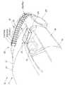
図1は本発明に係る第1実施形態の車両用衝突検知装置の通信方法を採用した車両の斜視図である。
図中、10は車両、11は車体、12はフロントバンパ、15ステアリング、16フロントピラー、17はフロントガラス、18は前ドア、19は後ドア、21はルーフ、22は前輪、24はドアミラー、であり、本発明に係る車両用衝突検知装置30は、フロントバンパフェース13内側に設けた複数のセンサ31a〜31pと、これらのセンサ31a〜31pの情報を受けるために車体11内に設けた制御部としてのSRS制御ユニット51と、からなる。The best mode for carrying out the present invention will be described below with reference to the accompanying drawings. The drawings are viewed in the direction of the reference numerals.
FIG. 1 is a perspective view of a vehicle that employs a communication method for a vehicle collision detection apparatus according to a first embodiment of the present invention.
In the figure, 10 is a vehicle, 11 is a vehicle body, 12 is a front bumper, 15 steering, 16 front pillars, 17 is a windshield, 18 is a front door, 19 is a rear door, 21 is a roof, 22 is a front wheel, 24 is a door mirror, The vehicle
SRSとは、Supplementary Restraint Systemの略であり、SRSはエアバッグ等を指す。なお、シートベルトは主拘束装置である。
また、センサ31a〜31pは、同一構造の部品であり、それぞれにセンサ31a〜31p自身の識別値(IDデータ)を記憶したものである。SRS is an abbreviation for Supplementary Restraint System, and SRS indicates an airbag or the like. The seat belt is a main restraint device.
The
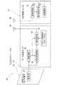
図2は本発明に係る第1実施の形態の車両用衝突検知装置のブロック図であり、センサ31aは、圧電フィルムセンサ素子32と、この圧電フィルムセンサ素子32に付設したデータ送信チップ33と、からなる。
圧電フィルムセンサ素子32は、外力の入力を利用して電力を発生してデータ送信チップ33に電力を供給するとともにデータ送信チップ33に信号電圧を発信する発電部34を備える。FIG. 2 is a block diagram of the vehicle collision detection apparatus according to the first embodiment of the present invention. The
The piezoelectric
データ送信チップ33は、自身の識別値としてのIDデータ41aを記憶した識別値記憶部としてのIDデータ記憶部42と、発電部34から信号電圧を受けて加速度及び/又は変位に対応する出力信号を処理する信号処理回路43と、この信号処理回路43で処理した出力信号及びIDデータ記憶部42に記憶したIDデータ41aを同時にSRS制御ユニット51に送る信号送信部44と、発電部34から電力の供給を受けて信号処理回路43及び信号送信部44に電源を供給するチップ側電源回路45と、からなる。 The
なお、49はチップ側アンテナを示す。また、IDとはidentity(同一であること、同一性、一致)の略である。さらに、図1に示すセンサ31b〜31pにも、それぞれ識別値としてのIDデータ41b〜41pを備える。
SRS制御ユニット(制御部)51は、データ送信チップ33の信号送信部44からの出力信号を受信する信号受信部52と、この信号受信部52からの情報で車両に衝突かあったかどうかを検知(判断)する衝突検知手段(衝突判断手段)53と、これらの信号受信部52及び衝突検知手段53に電源を供給するユニット側電源回路54と、を備える。 なお、59はユニット側アンテナを示す。 The SRS control unit (control unit) 51 detects whether or not the vehicle has collided with the
すなわち、車両用衝突検知装置30の通信方法は、車体11(図1参照)に作用する加速度及び/又は変位を検出する複数のセンサ31a〜31p(図1参照)と、これらセンサ31a〜31pからの信号を受信して衝突の判定を行うSRS制御ユニット(制御部)51と、を無線方式で結んだ車両用衝突検知装置の通信方法であって、センサ31aに、外力の入力を利用して電力を発生する発電部34と、この発電部34からの電力で車体に作用する加速度及び/又は変位に対応する出力信号を発生させる信号処理回路43と、センサ自身のIDデータ(識別値)41aを記憶するIDデータ記憶部(識別値記憶部)42と、を備え、発電部34から供給する電力でSRS制御ユニット51に、IDデータ(識別値)41a〜41p及び出力信号を同時に送信するようにしたものと言える。 That is, the communication method of the vehicle
センサ31aに、外力の入力を利用して電力を発生する発電部34と、この発電部34からの電力で車体に作用する加速度及び/又は変位に対応する出力信号を発生させる信号処理回路43と、センサ自身のIDデータ(識別値)41aを記憶するIDデータ記憶部(識別値記憶部)42と、を備えたので、発電部34で発生させた電力を用い、信号処理回路43で加速度及び/又は変位に対応する出力信号を処理することができるとともに、発電部34から供給する電力でSRS制御ユニット(制御部)51に、IDデータ(識別値)41a〜41p及び出力信号を同時に送信することができる。 A power generation unit 34 that generates electric power by using an external force input to the
これにより、例えば、センサと制御部とを結ぶハーネスなどを取去り、センサ31a〜31p(図1参照)とSRS制御ユニット(制御部)51とを無線方式で結合することができる。この結果、車両用衝突検知装置30を簡易(シンプル)に構成することができるとともに、車両用衝突検知装置30のレイアウトの多様化を図ることができる。 Thereby, the harness etc. which connect a sensor and a control part are removed, for example, and
また、センサ31aに、外力の入力を利用して電力を発生する発電部34を備えることで、例えば、供給電源を省くことができる。この結果、消費電力の節減を図ることができる車両用衝突検知装置30を実現することができる。 Further, by providing the
図3(a),(b)は本発明に係る第1実施形態の車両用衝突検知装置の作用説明図である。
(a)において、待機状態の車両用衝突検知装置30を示し、センサ31a〜31pからのIDデータ(識別値)41a〜41p及びセンサ31a〜31pからの出力信号をSRS制御ユニット51で待機する。FIGS. 3A and 3B are explanatory views of the operation of the vehicle collision detection apparatus according to the first embodiment of the present invention.
In (a), the vehicle
(b)において、障害物39でフロントバンパフェース13が変形することで、障害物39の近傍のセンサ31h,31i,31jが変形することで、センサ31h,31i,31jから、それぞれにIDデータ41h,41i,41j及びそれぞれの出力信号をSRS制御ユニット51に送信する。これにより、SRS制御ユニット51では、車体11に作用する加速度及び/又は変位、若しくは変形位置に対応させてエアバッグ(不図示)やシートベルトなどの作動を調整することができる。 In (b), the
図4は本発明に係る第2実施の形態の車両用衝突検知装置のブロック図であり、車両用衝突検知装置30(図1及び図2参照)と同一部品は同一符号を用い詳細な説明は省略する。
本発明に係る車両用衝突検知装置60は、フロントバンパフェース13(図1参照)内側に設けた複数のセンサ61a〜61pと、これらのセンサ61a〜61pの情報を受けるために車体11内に設けた制御部としてのSRS制御ユニット51と、からなる。FIG. 4 is a block diagram of a vehicle collision detection device according to a second embodiment of the present invention. The same parts as those of the vehicle collision detection device 30 (see FIGS. 1 and 2) are denoted by the same reference numerals, and detailed description thereof will be given. Omitted.
A vehicle
センサ61aは、圧電フィルムセンサ素子62と、この圧電フィルムセンサ素子62に付設したデータ送信チップ63と、からなる。
圧電フィルムセンサ素子62は、外力の入力を利用して電力を発生してデータ送信チップ63に電力を供給するとともにデータ送信チップ63に信号電圧を発信する発電部64と、この発電部64で発電した電力を蓄える電力蓄積部65と、を備える。The
The piezoelectric
データ送信チップ63は、自身の識別値としてのIDデータ71aを記憶した識別値記憶部としてのIDデータ記憶部72と、発電部64から信号電圧を受けて加速度及び/又は変位に対応する出力信号を処理する信号処理回路73と、この信号処理回路73で処理した出力信号及びIDデータ記憶部72に記憶したIDデータ71aを同時にSRS制御ユニット51に送る信号送信部74と、発電部64から電力の供給を受けて信号処理回路73及び信号送信部74に電源を供給するチップ側電源回路75と、からなる。 The
なお、79はチップ側アンテナを示す。また、センサ31b〜31pにも、それぞれ識別値としてのIDデータ(不図示)を備える。図中、51はSRS制御ユニット(制御部)、52は信号受信部、53は衝突検知手段、54はユニット側電源回路、59はユニット側アンテナを示す。
すなわち、車両用衝突検知装置60の通信方法は、車体11(図1参照)に作用する加速度及び/又は変位を検出する複数のセンサ61a〜61pと、これらのセンサ61a〜61pからの信号を受信して衝突の判定を行うSRS制御ユニット(制御部)51と、を無線方式で結んだ車両用衝突検知装置の通信方法であって、センサ61aに、外力の入力を利用して電力を発生する発電部64と、この発電部64で発電した電力を蓄える電力蓄積部65と、発電部64からの電力で車体11に作用する加速度及び/又は変位に対応する出力信号を発生させる信号処理回路73と、センサ61a自身のIDデータ(識別値)71aを記憶するIDデータ記憶部(識別値記憶部)72と、を備え、電力蓄積部65から供給する電力でSRS制御ユニット51に、IDデータ(識別値)71a及び出力信号を同時に送信するようにしたものと言える。 That is, the communication method of the vehicle
センサ61aに、外力の入力を利用して電力を発生する発電部64と、この発電部64で発電した電力を蓄える電力蓄積部65と、発電部64からの電力で車体11に作用する加速度及び/又は変位に対応する出力信号を発生させる信号処理回路73と、センサ61a自身のIDデータ(識別値)71aを記憶するIDデータ記憶部(識別値記憶部)72と、を備えたので、電力蓄積部65に蓄えた電力を用い、信号処理回路73で加速度及び/又は変位に対応する出力信号を処理することができるとともに、電力蓄積部65に蓄えた電力でSRS制御ユニット(制御部)51に、IDデータ(識別値)71a及び出力信号を同時に送信することができる。この結果、さらなる安定したセンサ61aの信号処理及びさらなる安定した出力信号の送信をすることができる。 A
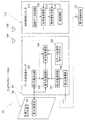
図5は本発明に係る第3実施形態の車両用衝突検知装置のブロック図であり、車両用衝突検知装置30(図1及び図2参照)と同一部品は同一符号を用い詳細な説明は省略する。
本発明に係る車両用衝突検知装置90は、フロントバンパフェース13(図1参照)内側に設けた複数のセンサ91a〜91p(図6に図示)と、これらのセンサ91a〜91pの情報を受けるために車体11内に設けた制御部としてのSRS制御ユニット111と、センサ91a〜91pに電波としてのマイクロ波で電力を供給する電力供給手段121と、からなる。FIG. 5 is a block diagram of a vehicle collision detection device according to a third embodiment of the present invention. The same components as those of the vehicle collision detection device 30 (see FIGS. 1 and 2) are denoted by the same reference numerals, and detailed description thereof is omitted. To do.
The vehicle
センサ91aは、圧電フィルムセンサ素子92と、この圧電フィルムセンサ素子92に付設したデータ送受信チップ93と、からなる。
圧電フィルムセンサ素子92は、外力の入力を利用して電力を発生してデータ送受信チップ93に電力を供給するとともにデータ送受信チップ93に信号電圧を発信する第1の発電部94を備える。The
The piezoelectric
データ送受信チップ93は、自身の識別値としてのIDデータ101aを記憶した識別値記憶部としてのIDデータ記憶部102と、第1の発電部94から信号電圧を受けて加速度及び/又は変位に対応する出力信号を処理する信号処理回路103と、この信号処理回路103で処理した出力信号及びIDデータ記憶部102に記憶したIDデータ101aを同時にSRS制御ユニット111に送る信号送受信部104と、第1の発電部94から電力の供給を受けて信号処理回路103及び信号送受信部104に電源を供給する第1の電源回路105と、電波としてのマイクロ波を受信して電力を発生する第2の発電部106と、この第2の発電部106から電力の供給を受けて信号処理回路103及び信号送受信部104に電源を供給する第2の電源回路107と、からなる。 The data transmission /
なお、109はチップ側アンテナを示す。また、センサ91b〜91pにも、それぞれ識別値としてのIDデータ101a〜101p(図7にて図示)を備える。
SRS制御ユニット(制御部)111は、データ送受信チップ93の信号送信部104からの出力信号を受信するとともに、故障診断データを送信する信号送受信部112と、この信号送受信部112からの情報で車両に衝突かあったかどうかを検知(判断)する衝突検知手段(衝突判断手段)113と、これらの信号送受信部112及び衝突検知手段113に電源を供給するユニット側電源回路114と、故障診断データを記憶させる診断データ記憶部115と、を備える。なお、119はユニット側アンテナを示す。 The SRS control unit (control unit) 111 receives an output signal from the
すなわち、車両用衝突検知装置90の通信方法は、車体11(図1参照)に作用する加速度及び/又は変位を検出する複数のセンサ91a〜91pと、これらのセンサ91a〜91pからの信号を受信して衝突の判定を行うとともに、センサ91a〜91pに故障診断データを送信してセンサの故障診断を行うSRS制御ユニット(制御部)111と、を無線方式で結んだ車両用衝突検知装置の通信方法であって、センサ91aに、外力の入力を利用して電力を発生する第1の発電部94と、マイクロ波(電波)を受信して電力を発生する第2の発電部106と、第1の発電部94からの電力で車体に作用する加速度及び/又は変位に対応する出力信号を発生させる信号処理回路103と、センサ91a自身のIDデータ(識別値)101aを記憶するIDデータ記憶部(識別値記憶部)102と、を備え、第1の発電部94から供給する電力でSRS制御ユニット111にIDデータ(識別値)101a及び出力信号を同時に送信するとともに、第2の発電部106から供給する電力でSRS制御ユニット111から送信する故障診断データを受信するようにしたものと言える。 That is, the communication method of the vehicle
センサ91aに、外力の入力を利用して電力を発生する第1の発電部94と、マイクロ波(電波)を受信して電力を発生する第2の発電部106と、第1の発電部94からの電力で車体に作用する加速度及び/又は変位に対応する出力信号を発生させる信号処理回路103と、センサ91a自身のIDデータ(識別値)101aを記憶するIDデータ記憶部(識別値記憶部)102と、を備えたので、第1の発電部94から供給する電力でSRS制御ユニット(制御部)111にIDデータ(識別値)101a及び出力信号を同時に送信するとともに、第2の発電部106から供給する電力でSRS制御ユニット111から送信する故障診断データを受信することができる。この結果、車両用衝突検知装置の信頼性の向上を図ることができる。 A first power generation unit 94 that generates power by using an external force input to the
図6(a),(b)は本発明に係る第3実施形態の車両用衝突検知装置の作用説明図であり、センサ91a〜91pの故障診断方法を示す、
(a)において、SRS制御ユニット111から各センサ91a〜91pに故障診断データを送信する。図5に示すように、各センサ91a〜91pはで、第2の発電部106から供給する電力を使用して故障診断データを受信する。6 (a) and 6 (b) are operation explanatory views of the vehicle collision detection device according to the third embodiment of the present invention, and show a failure diagnosis method for the
In (a), failure diagnosis data is transmitted from the
(b)において、各センサ91a〜91pからSRS制御ユニット111に故障診断結果を送信する。図5に示すように、各センサ91a〜91pでは、第2の発電部106から供給する電力を使用して故障診断結果を送信する。 In (b), a failure diagnosis result is transmitted from each of the
尚、本発明に係る車両用衝突検知装置の通信方法は、図4に示すように、フロントバンパ12に採用したが、これに限るものではなく、リヤバンパなどのその他ボデーに設けるものであってもよい。 As shown in FIG. 4, the communication method of the vehicle collision detection device according to the present invention is adopted in the
本発明に係る車両用衝突検知装置の通信方法は、図5に示すように、電力供給手段121からセンサ91a〜91pにマイクロ波にて電力を供給するようにしたが、これに限るものではなく、電波により電力を供給できるものであればよく、例えば、レーザー光線を用いるものであってもよい。さらに、SRS制御ユニット111から送信する電波としての故障診断データを用いて直接電力を供給する(発電する)ものであってもよい。 As shown in FIG. 5, the communication method of the vehicle collision detection apparatus according to the present invention supplies power from the power supply means 121 to the
本発明に係る車両用衝突検知装置の通信方法は、図5に示すように、第1の発電部94からの電力で車体11(図1参照)に作用する加速度及び/又は変位に対応する出力信号を信号処理回路103で発生させて信号送受信部104から送信したが、これに限るものではなく、第2の発電部106の電力を信号処理回路103及び信号送受信部104に供給することで、車体11(図1参照)に作用する加速度及び/又は変位に対応する出力信号を発生させて信号送受信部104から送信するものであってもよい。 As shown in FIG. 5, the communication method of the vehicle collision detection apparatus according to the present invention is an output corresponding to acceleration and / or displacement acting on the vehicle body 11 (see FIG. 1) with electric power from the first power generation unit 94. The signal is generated by the
本発明に係る車両用衝突検知装置の通信方法は、セダンやワゴンなどの乗用車に採用するのに好適である。 The vehicle collision detection apparatus communication method according to the present invention is suitable for use in passenger cars such as sedans and wagons.
10…車両、11…車体、30,60,90…車両用衝突検知装置、31a〜31p,61p〜61p,91a〜91p…センサ、34,64…発電部、41a〜41p,71a〜71p,101a〜101p…識別値(IDデータ)、42,72,102…識別値記憶部(IDデータ記憶部)、43,73,103…信号処理回路、51,111…制御部(SRS制御ユニット)、65…電力蓄積部、94…第1の発電部、106…第2の発電部。 DESCRIPTION OF
Claims (3)
Translated fromJapanese前記センサは、圧電フィルムセンサ素子と、この圧電フィルムセンサ素子に付設したデータ送信チップと、からなり、
前記圧電フィルムセンサ素子は、外力の入力を利用して電力を発生して前記データ送信チップに電力を供給するとともに前記データ送信チップに信号電圧を発信する発電部を備え、
前記データ送信チップは、前記発電部からの信号電圧を受けて前記車体に作用する加速度及び/又は変位に対応する出力信号を発生させる信号処理回路と、前記センサ自身の識別値を記憶する識別値記憶部と、を備え、
前記発電部から供給する電力で前記制御部に、前記識別値及び前記出力信号を同時に送信することを特徴とする車両用衝突検知装置の通信方法。A wireless systemthat is provided inside a front or rear bumper face and detects a plurality of sensors that detect acceleration and / or displacement actingon the vehicle body, and a control unit that receives signals from these sensors and determines a collision. A communication method for a vehicle collision detection apparatus connected by
The sensor comprises apiezoelectric film sensor element and a data transmission chip attached to the piezoelectric film sensor element,
The piezoelectric film sensor element includes a power generation unit that generates power using an input of external force to supply power to the data transmission chip and transmit a signal voltage to the data transmission chip,
The data transmission chipreceives asignal voltage from the power generation unit and generates an output signal corresponding to acceleration and / or displacement acting on the vehicle body, and an identification value for storing an identification value of the sensor itself A storage unit,
The vehicle collision detection apparatus communication method, wherein the identification value and the output signal are simultaneously transmitted to the control unit with electric power supplied from the power generation unit.
前記センサは、圧電フィルムセンサ素子と、この圧電フィルムセンサ素子に付設したデータ送信チップと、からなり、
前記圧電フィルムセンサ素子は、外力の入力を利用して電力を発生して前記データ送信チップに電力を供給するとともに前記データ送信チップに信号電圧を発信する発電部と、この発電部で発電した電力を蓄える電力蓄積部と、を備え、
前記データ送信チップは、前記発電部からの信号電圧を受けて前記車体に作用する加速度及び/又は変位に対応する出力信号を発生させる信号処理回路と、前記センサ自身の識別値を記憶する識別値記憶部と、を備え、
前記電力蓄積部から供給する電力で前記制御部に、前記識別値及び前記出力信号を同時に送信することを特徴とする車両用衝突検知装置の通信方法。A plurality of sensorsthat are provided inside the front or rear bumper face and detect acceleration and / or displacement actingon the vehicle body, and a control unit that receives signals from these sensors and determines a collision are wireless. A communication method for a vehicle collision detection device connected by a method,
The sensor comprises apiezoelectric film sensor element and a data transmission chip attached to the piezoelectric film sensor element,
The piezoelectric film sensor element generates power using an external force input to supply power to the data transmission chip and to transmit a signal voltage to the data transmission chip; and power generated by the power generation unit A power storage unit for storing
The data transmission chipreceives asignal voltage from the power generation unit and generates an output signal corresponding to acceleration and / or displacement acting on the vehicle body, and an identification value for storing an identification value of the sensor itself A storage unit,
The vehicle collision detection apparatus communication method, wherein the identification value and the output signal are simultaneously transmitted to the control unit with power supplied from the power storage unit.
前記センサは、圧電フィルムセンサ素子と、この圧電フィルムセンサ素子に付設したデータ送受信チップと、からなり、
前記圧電フィルムセンサ素子は、外力の入力を利用して電力を発生して前記データ送受信チップに電力を供給するとともに前記データ送受信チップに信号電圧を発信する第1の発電部を備え、
前記データ送受信チップは、電波を受信して電力を発生する第2の発電部と、前記第1の発電部からの信号電圧を受けて前記車体に作用する加速度及び/又は変位に対応する出力信号を発生させる信号処理回路と、前記センサ自身の識別値を記憶する識別値記憶部と、を備え、
前記第1の発電部若しくは第2の発電部から供給する電力で前記制御部に前記識別値及び前記出力信号を同時に送信するとともに、前記第2の発電部から供給する電力で前記制御部から送信する前記故障診断データを受信することを特徴とする車両用衝突検知装置の通信方法。A plurality of sensorsthat are installed inside the front or rear bumper face to detect acceleration and / or displacement actingon the vehicle body, receive signals from these sensors, determine collisions, and diagnose failures in the sensors A communication method for a vehicle collision detection apparatus that connects a control unit that transmits data and diagnoses a failure of a sensor in a wireless manner,
The sensor comprises apiezoelectric film sensor element and a data transmission / reception chip attached to the piezoelectric film sensor element,
The piezoelectric film sensor element includes a first power generation unit that generates power using an external force input to supply power to the data transmission / reception chip and transmit a signal voltage to the data transmission / reception chip,
The data transceiver chip, a second power generation unit for generating electric power by receiving a radio wave, the firstreceiving power generationunit or thesesignal voltage output corresponding to the acceleration and / or displacement acting on the vehicle body A signal processing circuit for generating a signal, and an identification value storage unit for storing an identification value of the sensor itself,
Transmits the identification value and the output signal to the control unit by electric power supplied from said first power generation unit or the second power generating unit at the same time, transmitted from the control unit with power supplied fromsaid second power generating unit And receiving the failure diagnosis data. A communication method for a vehicle collision detection device.
Priority Applications (2)
| Application Number | Priority Date | Filing Date | Title |
|---|---|---|---|
| JP2005238699AJP4620548B2 (en) | 2005-08-19 | 2005-08-19 | Communication method for vehicle collision detection device |
| US11/465,277US20070043507A1 (en) | 2005-08-19 | 2006-08-17 | Vehicle collision detection device |
Applications Claiming Priority (1)
| Application Number | Priority Date | Filing Date | Title |
|---|---|---|---|
| JP2005238699AJP4620548B2 (en) | 2005-08-19 | 2005-08-19 | Communication method for vehicle collision detection device |
Publications (2)
| Publication Number | Publication Date |
|---|---|
| JP2007050832A JP2007050832A (en) | 2007-03-01 |
| JP4620548B2true JP4620548B2 (en) | 2011-01-26 |
Family
ID=37768243
Family Applications (1)
| Application Number | Title | Priority Date | Filing Date |
|---|---|---|---|
| JP2005238699AExpired - Fee RelatedJP4620548B2 (en) | 2005-08-19 | 2005-08-19 | Communication method for vehicle collision detection device |
Country Status (2)
| Country | Link |
|---|---|
| US (1) | US20070043507A1 (en) |
| JP (1) | JP4620548B2 (en) |
Families Citing this family (9)
| Publication number | Priority date | Publication date | Assignee | Title |
|---|---|---|---|---|
| JP4726650B2 (en)* | 2006-02-24 | 2011-07-20 | 本田技研工業株式会社 | Vehicle sensor module |
| JP2008265643A (en)* | 2007-04-24 | 2008-11-06 | Calsonic Kansei Corp | Occupant protection device for vehicle |
| US8228208B2 (en)* | 2008-07-28 | 2012-07-24 | Westerngeco L.L.C. | Communication system for survey source and receiver |
| JP6086459B2 (en) | 2013-06-12 | 2017-03-01 | ボッシュ株式会社 | Control device and control system for controlling protection device for protecting vehicle occupant or pedestrian |
| JP6428514B2 (en)* | 2015-07-08 | 2018-11-28 | 株式会社デンソー | Vehicle collision detection device |
| WO2018146992A1 (en)* | 2017-02-09 | 2018-08-16 | 本田技研工業株式会社 | Mounting structure of external environment detection device for vehicle |
| US10926727B2 (en)* | 2017-10-18 | 2021-02-23 | Qirfiraz Siddiqui | Smart surface for detecting collision forces |
| US11532970B2 (en) | 2019-03-27 | 2022-12-20 | Richard A. Schulman | Energy conversion systems and methods |
| US20220371533A1 (en)* | 2021-05-18 | 2022-11-24 | Motional Ad Llc | Distributed vehicle body sensors for event detection |
Family Cites Families (10)
| Publication number | Priority date | Publication date | Assignee | Title |
|---|---|---|---|---|
| US6259372B1 (en)* | 1999-01-22 | 2001-07-10 | Eaton Corporation | Self-powered wireless transducer |
| JP3989309B2 (en)* | 2002-06-25 | 2007-10-10 | 本田技研工業株式会社 | Collision detection system |
| WO2005024750A1 (en)* | 2003-08-29 | 2005-03-17 | Ntn Corporation | Wireless sensor system, and bearing apparatus with wireless sensor |
| JP4175306B2 (en)* | 2003-09-18 | 2008-11-05 | 株式会社デンソー | Tire pressure monitoring system |
| JP2005092704A (en)* | 2003-09-19 | 2005-04-07 | Ntn Corp | Wireless sensor system and bearing device with wireless sensor |
| US7304566B2 (en)* | 2003-11-19 | 2007-12-04 | Honda Motor Co., Ltd. | Collision detection sensor for vehicle and collision detection device for vehicle |
| JP4083665B2 (en)* | 2003-11-19 | 2008-04-30 | 本田技研工業株式会社 | Vehicle collision detection device |
| JP2005193743A (en)* | 2004-01-05 | 2005-07-21 | Bridgestone Corp | Vehicle tire |
| JP2005247217A (en)* | 2004-03-05 | 2005-09-15 | Denso Corp | Power supply unit for on-vehicle equipment, and power supplying method of on-vehicle equipment |
| EP1588905A1 (en)* | 2004-04-22 | 2005-10-26 | IEE INTERNATIONAL ELECTRONICS & ENGINEERING S.A. | Seat sensor system |
- 2005
- 2005-08-19JPJP2005238699Apatent/JP4620548B2/ennot_activeExpired - Fee Related
- 2006
- 2006-08-17USUS11/465,277patent/US20070043507A1/ennot_activeAbandoned
Also Published As
| Publication number | Publication date |
|---|---|
| JP2007050832A (en) | 2007-03-01 |
| US20070043507A1 (en) | 2007-02-22 |
Similar Documents
| Publication | Publication Date | Title |
|---|---|---|
| CN111319522B (en) | Electrical assembly | |
| US10864876B2 (en) | Deployable panel for an airbag | |
| JP5886949B2 (en) | Device and method for activating occupant protection means, activation system and vehicle | |
| JP4620548B2 (en) | Communication method for vehicle collision detection device | |
| US8155842B2 (en) | Occupant protection device for vehicle | |
| US20180304847A1 (en) | Rotatably supported airbag | |
| CN113165553B (en) | Capacitive sensor protection diagnostics based on redundant coupling measurements | |
| US11472360B2 (en) | Restraint system operating method and restraint system for vehicle having detachable doors | |
| US7982590B2 (en) | Occupant restraint system | |
| JP4375372B2 (en) | Seat belt retractor | |
| US8113541B2 (en) | Vehicle supplemental restraint system configuration and method | |
| JP2015529174A (en) | Airbag sensor module and body integrated with airbag sensor module | |
| JP4076849B2 (en) | Start-up control device for airbag device | |
| JP2008155660A (en) | Crew status determination device | |
| JP2010155499A (en) | Vehicle collision detection device, occupant restraint system and vehicle | |
| EP2799279A1 (en) | A safety system for a detachable seat of a vehicle | |
| US20070013496A1 (en) | Collision detection device for vehicle | |
| JPH1178999A (en) | Airbag system for vehicle | |
| CN113306520A (en) | Driver airbag with extension adjacent to rear panel | |
| KR101621874B1 (en) | Airbag system, controlling method thereof and wearble device | |
| JP2005247217A (en) | Power supply unit for on-vehicle equipment, and power supplying method of on-vehicle equipment | |
| US20080290636A1 (en) | Device for Triggering Personal Protective Means | |
| US12344182B2 (en) | Airbag apparatus for vehicle and method of controlling operation of the same | |
| JP2009292375A (en) | Collision determination device | |
| CN220398411U (en) | Safety airbag is with leading steel wire joint detection frock |
Legal Events
| Date | Code | Title | Description |
|---|---|---|---|
| A621 | Written request for application examination | Free format text:JAPANESE INTERMEDIATE CODE: A621 Effective date:20071129 | |
| A977 | Report on retrieval | Free format text:JAPANESE INTERMEDIATE CODE: A971007 Effective date:20091106 | |
| A131 | Notification of reasons for refusal | Free format text:JAPANESE INTERMEDIATE CODE: A131 Effective date:20091125 | |
| A521 | Request for written amendment filed | Free format text:JAPANESE INTERMEDIATE CODE: A523 Effective date:20100119 | |
| A131 | Notification of reasons for refusal | Free format text:JAPANESE INTERMEDIATE CODE: A131 Effective date:20100803 | |
| A521 | Request for written amendment filed | Free format text:JAPANESE INTERMEDIATE CODE: A523 Effective date:20100809 | |
| A131 | Notification of reasons for refusal | Free format text:JAPANESE INTERMEDIATE CODE: A131 Effective date:20100831 | |
| A521 | Request for written amendment filed | Free format text:JAPANESE INTERMEDIATE CODE: A523 Effective date:20100921 | |
| TRDD | Decision of grant or rejection written | ||
| A01 | Written decision to grant a patent or to grant a registration (utility model) | Free format text:JAPANESE INTERMEDIATE CODE: A01 Effective date:20101026 | |
| A01 | Written decision to grant a patent or to grant a registration (utility model) | Free format text:JAPANESE INTERMEDIATE CODE: A01 | |
| A61 | First payment of annual fees (during grant procedure) | Free format text:JAPANESE INTERMEDIATE CODE: A61 Effective date:20101028 | |
| FPAY | Renewal fee payment (event date is renewal date of database) | Free format text:PAYMENT UNTIL: 20131105 Year of fee payment:3 | |
| R150 | Certificate of patent or registration of utility model | Free format text:JAPANESE INTERMEDIATE CODE: R150 | |
| LAPS | Cancellation because of no payment of annual fees |