JP4620465B2 - An embolic filter frame with looped support strut elements - Google Patents
An embolic filter frame with looped support strut elementsDownload PDFInfo
- Publication number
- JP4620465B2 JP4620465B2JP2004545447AJP2004545447AJP4620465B2JP 4620465 B2JP4620465 B2JP 4620465B2JP 2004545447 AJP2004545447 AJP 2004545447AJP 2004545447 AJP2004545447 AJP 2004545447AJP 4620465 B2JP4620465 B2JP 4620465B2
- Authority
- JP
- Japan
- Prior art keywords
- filter
- support
- struts
- frame
- present
- Prior art date
- Legal status (The legal status is an assumption and is not a legal conclusion. Google has not performed a legal analysis and makes no representation as to the accuracy of the status listed.)
- Expired - Fee Related
Links
- 230000003073embolic effectEffects0.000titleclaimsabstractdescription115
- 230000002829reductive effectEffects0.000abstractdescription4
- 238000007789sealingMethods0.000abstractdescription4
- 238000000034methodMethods0.000description14
- 239000000463materialSubstances0.000description11
- 238000006073displacement reactionMethods0.000description8
- 239000004812Fluorinated ethylene propyleneSubstances0.000description7
- 239000012530fluidSubstances0.000description7
- 230000001965increasing effectEffects0.000description7
- 229920009441perflouroethylene propylenePolymers0.000description7
- 239000000843powderSubstances0.000description5
- 235000020637scallopNutrition0.000description5
- 230000001225therapeutic effectEffects0.000description5
- 230000002792vascularEffects0.000description5
- 210000005166vasculatureAnatomy0.000description5
- 208000005189EmbolismDiseases0.000description4
- 241000237509Patinopecten sp.Species0.000description4
- 238000005452bendingMethods0.000description4
- 238000001914filtrationMethods0.000description4
- 238000010438heat treatmentMethods0.000description4
- 208000014674injuryDiseases0.000description4
- 229910001000nickel titaniumInorganic materials0.000description4
- 230000036961partial effectEffects0.000description4
- 239000002243precursorSubstances0.000description4
- 208000007536ThrombosisDiseases0.000description3
- 230000004888barrier functionEffects0.000description3
- 210000004204blood vesselAnatomy0.000description3
- 230000006835compressionEffects0.000description3
- 238000007906compressionMethods0.000description3
- 230000006378damageEffects0.000description3
- 230000000694effectsEffects0.000description3
- 238000013152interventional procedureMethods0.000description3
- 239000012528membraneSubstances0.000description3
- HLXZNVUGXRDIFK-UHFFFAOYSA-Nnickel titaniumChemical compound[Ti].[Ti].[Ti].[Ti].[Ti].[Ti].[Ti].[Ti].[Ti].[Ti].[Ti].[Ni].[Ni].[Ni].[Ni].[Ni].[Ni].[Ni].[Ni].[Ni].[Ni].[Ni].[Ni].[Ni].[Ni]HLXZNVUGXRDIFK-UHFFFAOYSA-N0.000description3
- 239000002245particleSubstances0.000description3
- 229920000642polymerPolymers0.000description3
- 229920001343polytetrafluoroethylenePolymers0.000description3
- 239000004810polytetrafluoroethyleneSubstances0.000description3
- 230000000452restraining effectEffects0.000description3
- 230000008733traumaEffects0.000description3
- XEEYBQQBJWHFJM-UHFFFAOYSA-NIronChemical compound[Fe]XEEYBQQBJWHFJM-UHFFFAOYSA-N0.000description2
- 238000004873anchoringMethods0.000description2
- 238000002399angioplastyMethods0.000description2
- 230000008901benefitEffects0.000description2
- 239000000560biocompatible materialSubstances0.000description2
- 239000008280bloodSubstances0.000description2
- 210000004369bloodAnatomy0.000description2
- 230000017531blood circulationEffects0.000description2
- 230000008859changeEffects0.000description2
- 238000005520cutting processMethods0.000description2
- 238000011161developmentMethods0.000description2
- 230000010102embolizationEffects0.000description2
- 238000005516engineering processMethods0.000description2
- 230000003902lesionEffects0.000description2
- 239000003550markerSubstances0.000description2
- 239000002184metalSubstances0.000description2
- 229910052751metalInorganic materials0.000description2
- 230000010412perfusionEffects0.000description2
- -1polytetrafluoroethylenePolymers0.000description2
- 230000008569processEffects0.000description2
- 238000005476solderingMethods0.000description2
- 239000007787solidSubstances0.000description2
- 238000012546transferMethods0.000description2
- 230000007704transitionEffects0.000description2
- 238000012800visualizationMethods0.000description2
- XLYOFNOQVPJJNP-UHFFFAOYSA-NwaterSubstancesOXLYOFNOQVPJJNP-UHFFFAOYSA-N0.000description2
- 206010011224CoughDiseases0.000description1
- 241001465754MetazoaSpecies0.000description1
- 241000237503PectinidaeSpecies0.000description1
- RTAQQCXQSZGOHL-UHFFFAOYSA-NTitaniumChemical compound[Ti]RTAQQCXQSZGOHL-UHFFFAOYSA-N0.000description1
- 208000027418Wounds and injuryDiseases0.000description1
- 239000000853adhesiveSubstances0.000description1
- 238000004026adhesive bondingMethods0.000description1
- 230000001070adhesive effectEffects0.000description1
- 230000002411adverseEffects0.000description1
- 208000007474aortic aneurysmDiseases0.000description1
- 238000005422blastingMethods0.000description1
- 230000036760body temperatureEffects0.000description1
- 238000005219brazingMethods0.000description1
- 238000007889carotid angioplastyMethods0.000description1
- 238000005266castingMethods0.000description1
- 230000001413cellular effectEffects0.000description1
- 238000006243chemical reactionMethods0.000description1
- 239000011248coating agentSubstances0.000description1
- 238000000576coating methodMethods0.000description1
- 238000004891communicationMethods0.000description1
- 238000007887coronary angioplastyMethods0.000description1
- 210000004351coronary vesselAnatomy0.000description1
- 238000013461designMethods0.000description1
- 201000010099diseaseDiseases0.000description1
- 208000037265diseases, disorders, signs and symptomsDiseases0.000description1
- 238000005553drillingMethods0.000description1
- 239000013013elastic materialSubstances0.000description1
- 238000009760electrical discharge machiningMethods0.000description1
- 238000005530etchingMethods0.000description1
- HQQADJVZYDDRJT-UHFFFAOYSA-Nethene;prop-1-eneChemical groupC=C.CC=CHQQADJVZYDDRJT-UHFFFAOYSA-N0.000description1
- 239000000835fiberSubstances0.000description1
- 238000007667floatingMethods0.000description1
- 230000009969flowable effectEffects0.000description1
- 229920002313fluoropolymerPolymers0.000description1
- 239000004811fluoropolymerSubstances0.000description1
- 238000002594fluoroscopyMethods0.000description1
- 239000011888foilSubstances0.000description1
- 239000007789gasSubstances0.000description1
- 230000001939inductive effectEffects0.000description1
- 238000003780insertionMethods0.000description1
- 230000037431insertionEffects0.000description1
- 229910052742ironInorganic materials0.000description1
- 230000001788irregularEffects0.000description1
- 208000028867ischemiaDiseases0.000description1
- 230000000302ischemic effectEffects0.000description1
- 238000005304joiningMethods0.000description1
- 239000007788liquidSubstances0.000description1
- 238000004519manufacturing processMethods0.000description1
- 239000011159matrix materialSubstances0.000description1
- 239000000203mixtureSubstances0.000description1
- 238000012986modificationMethods0.000description1
- 230000004048modificationEffects0.000description1
- 238000000465mouldingMethods0.000description1
- 238000009740moulding (composite fabrication)Methods0.000description1
- 239000013618particulate matterSubstances0.000description1
- 229920001296polysiloxanePolymers0.000description1
- 238000012545processingMethods0.000description1
- 210000002254renal arteryAnatomy0.000description1
- 230000008439repair processEffects0.000description1
- 230000000250revascularizationEffects0.000description1
- 230000002441reversible effectEffects0.000description1
- 210000003752saphenous veinAnatomy0.000description1
- HBMJWWWQQXIZIP-UHFFFAOYSA-Nsilicon carbideChemical compound[Si+]#[C-]HBMJWWWQQXIZIP-UHFFFAOYSA-N0.000description1
- 229910010271silicon carbideInorganic materials0.000description1
- 229910001220stainless steelInorganic materials0.000description1
- 239000010935stainless steelSubstances0.000description1
- 230000002966stenotic effectEffects0.000description1
- 238000003860storageMethods0.000description1
- 238000001356surgical procedureMethods0.000description1
- 238000012360testing methodMethods0.000description1
- 229920001169thermoplasticPolymers0.000description1
- 239000004416thermosoftening plasticSubstances0.000description1
- 239000010936titaniumSubstances0.000description1
- 229910052719titaniumInorganic materials0.000description1
- 238000011144upstream manufacturingMethods0.000description1
- 238000003466weldingMethods0.000description1
Images


Classifications
- A—HUMAN NECESSITIES
- A61—MEDICAL OR VETERINARY SCIENCE; HYGIENE
- A61F—FILTERS IMPLANTABLE INTO BLOOD VESSELS; PROSTHESES; DEVICES PROVIDING PATENCY TO, OR PREVENTING COLLAPSING OF, TUBULAR STRUCTURES OF THE BODY, e.g. STENTS; ORTHOPAEDIC, NURSING OR CONTRACEPTIVE DEVICES; FOMENTATION; TREATMENT OR PROTECTION OF EYES OR EARS; BANDAGES, DRESSINGS OR ABSORBENT PADS; FIRST-AID KITS
- A61F2/00—Filters implantable into blood vessels; Prostheses, i.e. artificial substitutes or replacements for parts of the body; Appliances for connecting them with the body; Devices providing patency to, or preventing collapsing of, tubular structures of the body, e.g. stents
- A61F2/01—Filters implantable into blood vessels
- A61F2/0105—Open ended, i.e. legs gathered only at one side
- B—PERFORMING OPERATIONS; TRANSPORTING
- B23—MACHINE TOOLS; METAL-WORKING NOT OTHERWISE PROVIDED FOR
- B23P—METAL-WORKING NOT OTHERWISE PROVIDED FOR; COMBINED OPERATIONS; UNIVERSAL MACHINE TOOLS
- B23P11/00—Connecting or disconnecting metal parts or objects by metal-working techniques not otherwise provided for
- A—HUMAN NECESSITIES
- A61—MEDICAL OR VETERINARY SCIENCE; HYGIENE
- A61F—FILTERS IMPLANTABLE INTO BLOOD VESSELS; PROSTHESES; DEVICES PROVIDING PATENCY TO, OR PREVENTING COLLAPSING OF, TUBULAR STRUCTURES OF THE BODY, e.g. STENTS; ORTHOPAEDIC, NURSING OR CONTRACEPTIVE DEVICES; FOMENTATION; TREATMENT OR PROTECTION OF EYES OR EARS; BANDAGES, DRESSINGS OR ABSORBENT PADS; FIRST-AID KITS
- A61F2/00—Filters implantable into blood vessels; Prostheses, i.e. artificial substitutes or replacements for parts of the body; Appliances for connecting them with the body; Devices providing patency to, or preventing collapsing of, tubular structures of the body, e.g. stents
- A61F2/01—Filters implantable into blood vessels
- A61F2002/018—Filters implantable into blood vessels made from tubes or sheets of material, e.g. by etching or laser-cutting
- A—HUMAN NECESSITIES
- A61—MEDICAL OR VETERINARY SCIENCE; HYGIENE
- A61F—FILTERS IMPLANTABLE INTO BLOOD VESSELS; PROSTHESES; DEVICES PROVIDING PATENCY TO, OR PREVENTING COLLAPSING OF, TUBULAR STRUCTURES OF THE BODY, e.g. STENTS; ORTHOPAEDIC, NURSING OR CONTRACEPTIVE DEVICES; FOMENTATION; TREATMENT OR PROTECTION OF EYES OR EARS; BANDAGES, DRESSINGS OR ABSORBENT PADS; FIRST-AID KITS
- A61F2230/00—Geometry of prostheses classified in groups A61F2/00 - A61F2/26 or A61F2/82 or A61F9/00 or A61F11/00 or subgroups thereof
- A61F2230/0002—Two-dimensional shapes, e.g. cross-sections
- A61F2230/0004—Rounded shapes, e.g. with rounded corners
- A61F2230/0006—Rounded shapes, e.g. with rounded corners circular
- A—HUMAN NECESSITIES
- A61—MEDICAL OR VETERINARY SCIENCE; HYGIENE
- A61F—FILTERS IMPLANTABLE INTO BLOOD VESSELS; PROSTHESES; DEVICES PROVIDING PATENCY TO, OR PREVENTING COLLAPSING OF, TUBULAR STRUCTURES OF THE BODY, e.g. STENTS; ORTHOPAEDIC, NURSING OR CONTRACEPTIVE DEVICES; FOMENTATION; TREATMENT OR PROTECTION OF EYES OR EARS; BANDAGES, DRESSINGS OR ABSORBENT PADS; FIRST-AID KITS
- A61F2230/00—Geometry of prostheses classified in groups A61F2/00 - A61F2/26 or A61F2/82 or A61F9/00 or A61F11/00 or subgroups thereof
- A61F2230/0063—Three-dimensional shapes
- A61F2230/0067—Three-dimensional shapes conical
- Y—GENERAL TAGGING OF NEW TECHNOLOGICAL DEVELOPMENTS; GENERAL TAGGING OF CROSS-SECTIONAL TECHNOLOGIES SPANNING OVER SEVERAL SECTIONS OF THE IPC; TECHNICAL SUBJECTS COVERED BY FORMER USPC CROSS-REFERENCE ART COLLECTIONS [XRACs] AND DIGESTS
- Y10—TECHNICAL SUBJECTS COVERED BY FORMER USPC
- Y10T—TECHNICAL SUBJECTS COVERED BY FORMER US CLASSIFICATION
- Y10T29/00—Metal working
- Y10T29/49—Method of mechanical manufacture
- Y10T29/49826—Assembling or joining
Landscapes
- Health & Medical Sciences (AREA)
- Engineering & Computer Science (AREA)
- Life Sciences & Earth Sciences (AREA)
- Animal Behavior & Ethology (AREA)
- Oral & Maxillofacial Surgery (AREA)
- Biomedical Technology (AREA)
- Heart & Thoracic Surgery (AREA)
- Vascular Medicine (AREA)
- Cardiology (AREA)
- Transplantation (AREA)
- General Health & Medical Sciences (AREA)
- Public Health (AREA)
- Veterinary Medicine (AREA)
- Mechanical Engineering (AREA)
- Surgical Instruments (AREA)
- Prostheses (AREA)
Abstract
Description
Translated fromJapanese本発明は、脈管構造及び、特に、塞栓フィルター要素を支持するのに使用される自己拡張フレームにおける配置用塞栓フィルター装置に関する。 The present invention relates to vasculature and in particular to an embolic filter device for placement in a self-expanding frame used to support an embolic filter element.
塞栓保護は、インターベンショナル(すなわち、経カテーテル)及び外科手術と関連した塞栓合併症の危険を減少しようとする高まりつつある臨床的重要性の概念である。治療的血管の処置において、塞栓片(例えば、血栓、凝塊、じゅく状斑等)が遊離すると、下流の脈管構造の潅流を妨げ、細胞性虚血及び/又は死を生じる。不利な塞栓合併症に最も一般的に関連する治療的血管処置には、補助ステント留置をともなうか又はともなわない頸動脈血管形成;及び退化伏在静脈グラフトの血管再開通などがある。さらに、補助ステント留置をともなうか又はともなわない経皮経管冠動脈形成術(PTCA)、外科冠動脈バイパス移植、経皮腎動脈血管再開通及び血管内大動脈瘤修復も、じゅく状塞栓に起因する合併症と関連している。したがって、塞栓片を捕捉し且つ除去する塞栓保護装置を使用すると、塞栓合併症の発生を減少により患者の転帰を改善できることがある。 Embolization protection is a concept of increasing clinical importance that seeks to reduce the risk of embolic complications associated with interventional (ie transcatheter) and surgery. In the treatment of therapeutic blood vessels, the release of embolic pieces (eg, thrombus, clots, plaques, etc.) prevents perfusion of downstream vasculature, resulting in cellular ischemia and / or death. Therapeutic vascular procedures most commonly associated with adverse embolic complications include carotid angioplasty with or without auxiliary stenting; and revascularization of degenerated saphenous vein grafts. In addition, percutaneous transluminal coronary angioplasty (PTCA) with or without auxiliary stent placement, surgical coronary artery bypass grafting, percutaneous renal artery vascular recanalization and endovascular aortic aneurysm repair are also complications due to constricted emboli Is associated with the disease. Thus, the use of an embolic protection device that captures and removes embolic strips may improve patient outcomes by reducing the occurrence of embolic complications.
塞栓保護装置は、典型的には凝血又はプラークのソースと下流の脈管構造との間の介在バリヤーとしての役割を果たす。塞栓保護の非常に数多くの装置及び方法が、経皮介在処置とともに補助的に使用されてきた。これらの方法は、異なるけれども、管腔内デリバリ;柔軟性;追跡性;狭窄損傷のクロシングを可能とする小デリバリプロファイル;通常の介在の実行との寸法的な適合性;フロー摂動を最小にする能力;凝血抵抗性;管腔断面全体に対するバリヤーの追従性(不規則であっても);及び塞栓保護装置及び捕捉された粒状物を安全に除去する手段を含む、多数の所望の特徴を有している。塞栓保護をおこなうのに2つの一般的な方法がある:閉塞バルーンを用いる方法;及び塞栓フィルターを用いる方法。塞栓フィルターの使用は、装置に対して下流の脈管構造の連続灌流が可能となるので、塞栓保護をおこなう所望の手段である。 The embolic protection device typically serves as an intervening barrier between the clot or plaque source and the downstream vasculature. A vast number of devices and methods for embolism protection have been used in conjunction with percutaneous interventional procedures. Although these methods differ, intraluminal delivery; flexibility; traceability; small delivery profiles that allow for stenotic injury crossing; dimensional compatibility with normal intervention practices; minimizing flow perturbations Ability to clot; barrier followability (even irregular) across the luminal section; and a number of desirable features including embolic protection devices and means to safely remove trapped particulate matter is doing. There are two common methods for embolic protection: using an occlusion balloon; and using an embolic filter. The use of an embolic filter is a desirable means of embolic protection because it allows continuous perfusion of the vasculature downstream from the device.
閉塞バルーン法は、従来技術により教示されており、病変に対して遠位の脈管構造への血液流が、介在位置の下流に位置している閉塞バルーンのインフレーションによりブロックされる装置を備えている。治療の後に、病変部位と閉塞バルーンとの間の管腔内コンパートメントを吸引して、介在処置中に遊離した可能性のある血栓又はじゅく状片を排出する。閉塞バルーン法の主な欠点は、作動中、遠位の血液流が完全に妨げられ、虚血性疼痛、遠うっ血/血栓、及び処置した血管部分を介してのコントラストウォッシュアウトによる蛍光透視可視化の困難を生じることがあることが原因である。 The occlusion balloon technique is taught by the prior art and comprises a device in which blood flow to the vasculature distal to the lesion is blocked by inflation of an occlusion balloon located downstream of the intervening location. Yes. Following treatment, the intraluminal compartment between the lesion site and the occlusion balloon is aspirated to expel any thrombus or cough that may have been released during the interventional procedure. The main drawback of the occlusion balloon method is that during operation, the distal blood flow is completely blocked, making it difficult to visualize fluoroscopy with ischemic pain, hypercongestion / thrombosis, and contrast washout through the treated vessel segment. The cause is that this may occur.
米国特許第4,723,549号(Wholey等)に記載されている従来のシステムは、治療用カテーテル(例えば、血管形成バルーン)と一体遠位塞栓フィルターとを組み合わせたものである。血管形成バルーンカテーテル等のカテーテルの遠位端に多孔質フィルター又は塞栓バリヤーを組み込むことにより、介在処置中に遊離した粒状物を、塞栓に関与する同じ治療装置により捕捉し且つ除去することができる。一つの公知の装置は、バルーンカテーテルの末端上に拡張バルーンに対して遠位に位置させた折り畳みフィルター装置を備えている。このフィルターは、拡張バルーンの方向に軸方向に延びているカテーテルの周囲に固定して複数の弾力性リブを備えている。フィルター材料は、リブ及びリブ間に固定されている。フィルターは、フィルターバルーンを膨らませてカップ状トラップ形成するときに展開する。しかしながら、フィルターは、内部容器壁の周囲に必ずしもシールしない。したがって、粒子が、フィルターと容器壁との間を通過する。また、装置は、縦方向の追従性も欠いている。したがって、カテーテルが不注意で移動すると、フィルターが縦方向に平行移動し、容器壁の損傷が生じ、塞栓片が遊離されることがある。 The conventional system described in US Pat. No. 4,723,549 (Wholey et al.) Combines a therapeutic catheter (eg, an angioplasty balloon) and an integral distal embolic filter. By incorporating a porous filter or embolic barrier at the distal end of a catheter, such as an angioplasty balloon catheter, particulates released during the interventional procedure can be captured and removed by the same therapeutic device involved in the embolization. One known device includes a folding filter device positioned distal to the dilatation balloon on the distal end of the balloon catheter. The filter includes a plurality of resilient ribs secured around a catheter extending axially in the direction of the dilatation balloon. The filter material is fixed between the ribs. The filter is deployed when the filter balloon is inflated to form a cup-shaped trap. However, the filter does not necessarily seal around the inner container wall. Thus, particles pass between the filter and the container wall. The device also lacks longitudinal followability. Therefore, if the catheter is inadvertently moved, the filter may translate longitudinally, causing damage to the container wall and releasing the embolic piece.
他の従来のシステムでは、ガイドワイヤと塞栓フィルターとを組み合わせている。塞栓フィルターは、血管内血液濾過のために、ガイドワイヤシステムの遠位端に直接組み込まれている。外科的処置及び介在処置のプラクティスの現在の傾向を前提として、これらの装置は、可能性のある用途において最も用途が広い可能性がある。これらのシステムの代表的なものは、機械的に多孔質フィルター要素を支持するガイドワイヤに取付けられたフィルターフレームである。このフィルターフレームは、放射状に配向したストラット、一つ以上の円形フープ又は予備付形バスケット形態を容器に配置して備えていることがある。フィルター要素は、典型的には高分子又は金属メッシュネットをフィルターフレーム及び/又はガイドワイヤに取付けて備えている。作動中、容器を介して流れる血液は、メッシュフィルター要素を強制的に通過させられることにより、フィルターに塞栓材料が捕捉される。 Other conventional systems combine a guide wire and an embolic filter. The embolic filter is incorporated directly into the distal end of the guidewire system for intravascular blood filtration. Given the current trends in surgical and interventional practice, these devices may be most versatile in potential applications. Typical of these systems is a filter frame attached to a guide wire that mechanically supports a porous filter element. The filter frame may be provided with radially oriented struts, one or more circular hoops or pre-shaped basket configurations disposed on the container. The filter element typically comprises a polymer or metal mesh net attached to the filter frame and / or guide wire. In operation, blood flowing through the container is forced through the mesh filter element, thereby trapping the embolic material in the filter.
この種の初期の装置は、当該技術分野、例えば、米国特許第5,695,519号(Summers等)に記載されており、塞栓を取り込み、保持するための中空ガイドワイヤに取り付けて取り外し可能な血管内フィルターを備えている。このフィルターは、フィルターから中空チューブに延びそこを貫通し、近位端まで延びている作動ワイヤを操作することにより展開することができる。容器内での配置の間、フィルター材料は、完全には拘束されず、装置が凝血塊を通り、通り越して配置されると、フィルター材料に凝血物質がひっかかり、展開前に塞栓が自由に動く恐れがある。また、この装置は、縦方向の追従性を欠いている。 Early devices of this type are described in the art, for example, US Pat. No. 5,695,519 (Summers et al.) And can be attached to and removed from a hollow guidewire for capturing and retaining emboli. Has an intravascular filter. The filter can be deployed by manipulating an actuation wire that extends from the filter to the hollow tube, extends therethrough, and extends to the proximal end. During placement within the container, the filter material is not fully constrained, and if the device is placed past and through the clot, the filter material may become clogged and the embolus may move freely before deployment. There is. In addition, this device lacks longitudinal followability.
従来の装置の別の例である米国特許第5,814,064号(Daniel等)に教示されている装置では、塞栓捕捉装置をガイドワイヤの遠位端に取り付けて使用している。フィルター材料を、ガイドワイヤの遠位部に連結し、ガイドワイヤの長さ部を走っている内腔と連通している流体活性化拡張性部材により容器の内腔にわたって拡張させる。位置決め中、装置が凝血塊を通り、越えて通過すると、フィルター材料が、凝血塊と相互作用して塞栓を生成することがある。また、この装置は、縦方向の追従性を欠いている。 Another device taught in US Pat. No. 5,814,064 (Daniel et al.), Which is another example of a conventional device, uses an embolus capture device attached to the distal end of a guide wire. The filter material is connected to the distal portion of the guidewire and expanded across the lumen of the container by a fluid activated expandable member in communication with the lumen running the length of the guidewire. During positioning, as the device passes through and beyond the clot, the filter material may interact with the clot and create an embolus. In addition, this device lacks longitudinal followability.
浮遊片及びフィルターにおける塞栓を集めるためにボディベッセルに展開するようにされている米国特許第6,152,946号(Broome等)に教示されている別の装置は、折り畳み可能な近接してテーパーを付けたフレームを、折り畳んだ装入プロファイルと拡張された展開プロファイルとの間にフィルターを支持するようにして備えている。テーパーを付けた折り畳み可能なフレームは、拡張され且つ展開されたプロファイルでボディベッセルの壁に延びる大きさの口と、フィルターフレームを支持ワイヤに取付け且つ固定する、実質的に縦のストラットとを備えている。この装置も、実質的に縦方向の追従性を欠いている。この装置は、テーパーを付けたフレームの縦方向に配向したストラット構成であるため、長さが長いというさらなる欠点がある。長さが長いために、曲がった組織内にフィルターをナビゲートし、配置することが複雑となる。 Another device taught in US Pat. No. 6,152,946 (Broom et al.) Adapted to be deployed in a body vessel to collect emboli in floating pieces and filters is a foldable proximal taper. And a frame with a support between the folded charging profile and the expanded deployment profile. The tapered foldable frame comprises a mouth sized to extend to the body vessel wall in an expanded and deployed profile and a substantially vertical strut that attaches and secures the filter frame to the support wire. ing. This device also substantially lacks longitudinal tracking. This device has the further disadvantage of a long length because of the strut configuration oriented in the longitudinal direction of the tapered frame. The long length complicates navigating and placing the filter within the bent tissue.
PCTWO98/33443にみられる別の例の塞栓フィルターシステムは、中央ガイドワイヤのケーブル又はスパインにフィルター材料を固定して有している。ガイドワイヤ内の移動可能なコア又は繊維を使用して、ケーブル又はスパインを、ガイドワイヤにほぼ平行な状態から、ガイドワイヤにほぼ垂直な状態に変えることができる。しかしながら、フィルターは、内部容器壁周囲にシールしないことがある。したがって、粒子が、フィルターと容器壁全体との間を通過することがある。この傘型装置は、展開されたときに浅く、除去のために閉じたときに粒子が逃げてしまう可能性がある。 Another example of an embolic filter system found in PCTWO 98/33443 has a filter material secured to a central guidewire cable or spine. A movable core or fiber in the guide wire can be used to change the cable or spine from being substantially parallel to the guide wire to being substantially perpendicular to the guide wire. However, the filter may not seal around the inner container wall. Thus, particles may pass between the filter and the entire container wall. This umbrella device is shallow when deployed and particles may escape when closed for removal.
要するに、従来の装置に関連する欠点には、縦方向の追従性の不足、フレームの展開長さが長いこと、関連するつなぎ留め要素、並びに不十分なアポジション及び容器壁に対するシールなどがある。縦方向の追従性がないと、フィルターカテーテル又は支持ワイヤが不注意により移動すると、展開されたフィルターが移動し、容器壁の損傷及び/又はイントロジェニック血管外傷、又は極端な場合には、塞栓片が遊離することがある。展開長さが長いと、血管側枝に隣接又はきつく曲がった容器内にフィルターを適切に展開できなくなる。フィルターのアポジション及び容器壁に対するシールが不適切であると、塞栓が通過する望ましくない影響が生じる。 In short, the disadvantages associated with conventional devices include lack of longitudinal followability, long unfolded frame length, associated tethering elements, and inadequate alignment and container wall seals. Without longitudinal follow-up, if the filter catheter or support wire is inadvertently moved, the deployed filter will move, causing damage to the container wall and / or introvascular vessel trauma, or, in extreme cases, an embolic strip. May be liberated. When the deployment length is long, the filter cannot be properly deployed in a container that is adjacent to or tightly bent on the side branch of the blood vessel. Inadequate filter placement and seals to the container wall can cause undesirable effects of emboli passage.
フィルターのアポジション及び容器壁に対するシールを確実にするために、過度の血管外傷を誘発せずに、容器壁に対するフィルターによりかかる半径方向力を最適化しなければならない。フィルターによりかかる半径方向力を増加するのに使用される典型的な方法には、例えば、フィルター支持フレーム、特にフレームのつなぎ留め要素の断面積(慣性モーメント及びしたがって、剛さ)を増加することなどがある。半径方向力は、追加の支持部材を組み込むか、又は展開される容器の直径に対するフィルターフレームの「弛緩」又は展開直径を増加させることにより増加させることができる。これらの方法は、典型的には縦方向の追従性を低下させ、圧縮デリバリプロファイルに付加され、場合によっては、展開長さが増加する望ましくない副次的な悪影響を及ぼす。半径方向力(例えば、より剛い支持フレーム)を増加するのに使用されるある方法では、より大きな壁厚、より大きなプロファイルのデリバリカテーテルを必要とするさらなる欠点がある。剛いフレーム(デリバリカテーテル内に拘束されている)により加えられる増加した圧力に適応するために、同等に厚くしたカテーテル壁が必要であり、デリバリプロファイルが悪くなる。 In order to ensure filter alignment and sealing against the container wall, the radial force applied by the filter against the container wall must be optimized without inducing excessive vascular trauma. Typical methods used to increase the radial force exerted by the filter include, for example, increasing the cross-sectional area (moment of inertia and hence stiffness) of the filter support frame, particularly the tethering element of the frame. There is. The radial force can be increased by incorporating additional support members or by increasing the “relaxed” or deployed diameter of the filter frame relative to the diameter of the deployed container. These methods typically reduce the longitudinal followability, add to the compression delivery profile, and in some cases have undesirable side effects that increase the unfold length. Certain methods used to increase radial forces (eg, stiffer support frames) have the additional disadvantage of requiring larger wall thickness, larger profile delivery catheters. To accommodate the increased pressure exerted by the rigid frame (constrained within the delivery catheter), an equivalently thick catheter wall is required, resulting in a poor delivery profile.
本発明によれば、ループ状支持ストラットを備えた改善された塞栓フィルターフレームが提供される。本発明のフレーム構成により、縦方向の追従性が改善され、容器壁に対するシールが改善され、デリバリプロファイルが小さく、フレーム及びつなぎ留め要素により占められる展開長さを短くできる。 In accordance with the present invention, an improved embolic filter frame with looped support struts is provided. The frame configuration of the present invention improves the longitudinal followability, improves the seal against the container wall, reduces the delivery profile, and shortens the deployed length occupied by the frame and tethering elements.
容器壁に対するアポジション及びシールを改善するために、本発明によれば、「ループ状」の支持ストラットを備えたフィルター支持フレームを組み込む。「ループ状」ストラット構成により、上記した望ましくない悪影響を生じることなく、容器壁に付与される半径方向力を高められる。また、ループ状ストラット構成により、曲がりくねった血管組織において展開するときに、フィルターフレームの付加が容易となる。引張り又は圧縮デリバリ状態にあるときには、本発明のループ状支持ストラットは、実質的に縦の構成をとり、最小の半径方向力をカテーテル壁に付与する。したがって、カテーテル壁又は半径方向の拘束の厚さを最小限として、可撓性を増加し、カテーテルプロファイルを減少させ、挿入追跡性を高めることができる。展開操作中、ループ状支持ストラットは、ループ状形態をとる。一旦展開されてループ状形態となると、支持ストラットは、高度の半径方向力を容器壁に加え、アポジション及びシール性が高まる。また、ループ状支持ストラットにより、従来の設計よりも高度の縦方向追従性が得られる。さらに、ループ状支持ストラットの全長が、フィルター要素に極めて近接して位置され、フィルター媒体支持要素の総展開長さが最小限となる。 In order to improve the positioning and sealing with respect to the container wall, according to the present invention, a filter support frame with “looped” support struts is incorporated. The “looped” strut configuration increases the radial force applied to the container wall without causing the undesirable effects described above. Also, the loop strut configuration facilitates the addition of a filter frame when deployed in tortuous vascular tissue. When in tension or compression delivery, the looped support struts of the present invention take a substantially vertical configuration and apply minimal radial force to the catheter wall. Thus, the thickness of the catheter wall or radial restraint can be minimized to increase flexibility, reduce catheter profile, and enhance insertion tracking. During the deployment operation, the looped support strut takes a looped configuration. Once deployed into a looped configuration, the support strut applies a high degree of radial force to the container wall, increasing the alignment and sealing properties. The loop support struts also provide a higher degree of longitudinal followability than conventional designs. Furthermore, the overall length of the looped support struts is located very close to the filter element, minimizing the total deployed length of the filter media support element.
本発明の重要な利点の中に、本発明の展開装置の「縦方向」剛さが小さいことが含まれる。すなわち、展開された状態において、装置は、縦方向において柔軟且つ弾性がある。その結果、支持ワイヤ又はカテーテルの縦方向の小さなずれは、ガイドワイヤ操作中、フィルターフレーム及び容器壁には移らない。 Among the important advantages of the present invention are the low “longitudinal” stiffness of the deployment device of the present invention. That is, in the deployed state, the device is flexible and elastic in the longitudinal direction. As a result, small longitudinal displacements of the support wire or catheter do not transfer to the filter frame and container wall during guide wire operation.
本発明の別の有益な特徴に、ループ状ストラット、及び本発明の支持ストラットを支持ワイヤに接続している中央カラーは、実質的にフィルター開口面内に位置し、必要に応じて、フィルターフレーム要素自体の内部にさえ配置させることができることがある。これにより、フィルター支持フレームの総展開長さを減少させ、フィルターを処置部位に非常に近接させて配置できるようにすることにより、本発明の塞栓フィルターの有用性を改善することができる。 Another advantageous feature of the present invention is that the loop struts and the central collar connecting the support struts of the present invention to the support wires are located substantially within the filter opening surface and, optionally, a filter frame. Sometimes it can even be placed inside the element itself. This can improve the utility of the embolic filter of the present invention by reducing the total deployed length of the filter support frame and allowing the filter to be placed very close to the treatment site.
本発明の塞栓フィルターの向上した特徴及び他の特性は、以下の記載を参照することによりよりよく理解されるであろう。 The improved features and other characteristics of the embolic filter of the present invention will be better understood by reference to the following description.
本発明の作用は、以下の説明を添付図面に関連して考慮したときに明らかとなろう。 The operation of the present invention will become apparent when the following description is considered in conjunction with the accompanying drawings.
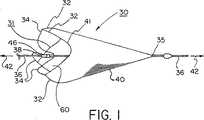
本発明の第一実施態様を、図1に示す。すなわち、図1は、本発明の未拘束非引張り状態の塞栓フィルターアセンブリ30を示す。フィルターアセンブリ30は、2つの異なる部分、フィルター支持部32及び一連のループ状ストラット又はテザー34を有するフレーム31を備えている。各ループ状ストラット34を、中央カラー46に付け、その後、取付け点38で支持ワイヤ36に取付ける。複数のストラット34が、外側に放射状に広がり、フレームのフィルター支持部32に取付けられる。フィルター支持部32に、フィルター要素40を取付ける。また、縦軸42も示されており、これは、支持ワイヤ36と実質的に一致している。 A first embodiment of the present invention is shown in FIG. That is, FIG. 1 shows an unconstrained, non-tensioned
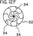
本発明の塞栓フィルターフレームは、2、3、4、5、6、7、8又はそれ以上のループ状支持ストラットを有することができる。支持ストラット数により、フィルター膜開口60のプロファイル及び形状が決まる。例えば、明瞭化のために3つの支持ストラットしか示していない図1のフレーム形態は、典型的にはフィルター支持部32のプロファイルに従う3つの「スカラップ」41を有するフィルター開口が形成される。追加の支持ストラットを組み込むことにより、各スカラップ41の大きさ又はサイズが減少し、フィルター開口が、面内の円により近くなる。好ましい実施態様によれば、6つのループ状支持ストラットを、本発明のフレームに組み込む。フィルター要素をトリミングして、スカロップの輪郭に一致させて、流体の流れが曲がったり、ばらばらになったり、又は塞栓が不注意で通過するのを回避することができる。 The embolic filter frame of the present invention can have 2, 3, 4, 5, 6, 7, 8 or more loop support struts. The profile and shape of the
フィルター要素の遠位端35は、好ましくは支持ワイヤ36の周囲に摺動可能アタッチメントを備えて、フィルター要素が、圧縮寸法と展開寸法との間で支持ワイヤ36に対しての位置を変更できるようにすることが好ましい。さらに、遠位端35と支持要素との間の摺動可能界面により、フィルター要素が、フィルターアセンブリが本明細書に記載の縦方向コンプライアンスを受けたときでさえ、常に容器において完全に延びた状態のままとすることができる。別法として、又はさらに、フィルター要素は、フィルターフレームの位置に対して異なる遠位端位置を収容できる弾性材料から形成できる。 The
図2に、本発明の塞栓フィルター30の未拘束ループ状支持ストラットの拡大図を示す。フィルター支持部32と3つのループ状支持ストラット34を備えたフレーム31が示されている。また、支持ワイヤ36、中央カラー46、ワイヤアタッチメント点38を支持するためのカラー及びフィルター要素40も、示されている。図示されているのは、ループ状支持ストラット34が実質的に「S」字状である好ましい実施態様である。 FIG. 2 shows an enlarged view of an unconstrained loop support strut of the
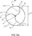
図3Aは、図1及び図2の未拘束塞栓フィルターアセンブリ30を示す。図では、3つの好ましいS字形ループ状支持ストラット34が、中央カラー46から放射状に延びている。支持ストラット34は、フィルター支持部32から延び、そこに取付けられている。フィルター支持部32には、フィルター要素40が取付けられている。未拘束状態で示されている塞栓フィルター30は、未拘束直径44を有している。 FIG. 3A shows the unrestrained
図2には、3つのループ状支持ストラット34と、支持ワイヤ36と、中央カラー46と、ワイヤアタッチメント点38を支持するためのカラーと、フィルター要素40が示されている。アタッチメント点38は、支持ワイヤ36と中央カラー46との間に剛性確保固定点を有するか、又は支持ワイヤ36と中央カラー46との間に摺動可能界面を有することができ、それにより、フィルターフレームから支持ワイヤの縦方向又は回転運動を切り離すことができる。支持ストラット34は、放射状に延び、フィルター支持部32に取付けられている。フィルター支持部32には、フィルター要素40が取付けられている。「フィルター支持部」は、フィルター要素40に少なくとも部分的に取付けられているフィルターフレームの部分として定義される。「支持ストラット」は、フィルター支持部を支持し、一般的にフィルター要素40に直接取付けられていないフィルターフレームの部分として定義される。 In FIG. 2, three looped support struts 34, a
「ループ状支持ストラット」を、さらに図3Bに示す。図では、支持ストラット34が、フィルター要素には取付けられておらず、支持ワイヤ又は縦軸42を中心として拘束されている。図示されているように支持ストラット34を通って描かれている基準軸47は、支持ストラットにおける曲がり又はループの大きさに近似している。軸47は、縦軸42に対する角度48を規定している。また、縦軸42に対する90度角を規定している基準軸49も示している。図では、縦軸42に対するループ状支持ストラット角48が90度を超える。したがって、「ループ状ストラット」は、フィルター要素に取付けられていない部分を有するフィルターフレーム支持ストラットであり、取付けられていない部分に沿って90度に等しいか、又は90度を超える少なくとも一つの曲がりを有しているストラットとして定義される。ループ状角は、いずれかの軸を中心としてみて、測定することができる。 A “looped support strut” is further illustrated in FIG. 3B. In the figure, support struts 34 are not attached to the filter element and are constrained about a support wire or
「S」字状のループ状塞栓フィルターフレーム支持ストラットを、図3Cに示す。図では、支持ストラット34が、フィルター要素に取付けられておらず、且つ縦軸42を中心として拘束されている。また、縦軸42に平行な軸37も示されている。図示されているように支持ストラット34を通過して描かれている基準軸47は、支持ストラットにおける曲がり又はループの大きさに近似している。軸47は、縦軸42に対する角度48を規定している。2つの対向する曲げ角度48も示されており、それらの各々は、少なくとも約90度である。「「S」字を有する支持ストラット」は、フィルター要素には取付けられていない部分を有するフィルターフレーム支持ストラットで、取付けられていない部分にそって約90度を超える少なくとも2つの対向する曲げ角度を有するストラットとして定義される。角度48は、いずれかの軸を中心としてみて、測定できる。 An “S” shaped looped embolic filter frame support strut is shown in FIG. 3C. In the figure, the
「縦方向コンプライアンス」の様子を、さらに図4に示す。弾性容器50(縦断面が示されている)内に配置された本発明の塞栓フィルターアセンブリ30が示されている。容器50は、装置の未拘束直径よりもわずかに小さい(例えば、約90%)内直径を規定している。これは、図3Aにおいて、直径44として示されている。したがって、「小さい」容器により、配置されたフィルターに対して半径方向の拘束がかかり、フィルターが完全な未拘束直径に拡張するのを防止できる。このプロセスにおいて、フィルターと容器壁との間の締まりばめが得られる。したがって、容器により拘束されたときに、ループ状支持ストラット34により、容器壁50に対して半径方向又は拡張力52がかかり、シール領域54が形成される。また、この半径方向、拡張力52は、容器壁に対してかかる「フープ応力」又は「半径方向力」とも称される。 The state of “vertical compliance” is further shown in FIG. Shown is an
本明細書において使用される用語「未拘束直径」は、テーブルトップに自己配置したときの本発明の装置を意味する。この形態では、未拘束且つ未引張り状態にある。また、この状態は、本明細書において「引張られていない」又は「非引張り」状態とも称する。 As used herein, the term “unconstrained diameter” means the apparatus of the present invention when it is self-placed on a table top. In this form, it is in an unconstrained and untensioned state. This state is also referred to herein as an “untensioned” or “non-tensioned” state.
展開されると、中央カラーに又は中央カラーを中心としてしっかりと固定されているとき、支持ワイヤ36は、大きな崩壊又はシール領域54に変換されることなく、方向56又は58に縦軸42に沿ってわずかに移動することができる。したがって、ループ状支持ストラット34により、フィルター要素を小さな支持ワイヤ変位から効果的に分離するある程度の「縦方向コンプライアンス」が得られる。未拘束直径約6mm(0.24”)を有する本発明の装置は、大きな崩壊又はシール領域54に変換することなく、約+/−0.8mm(+/−0.03”)又はそれ以上の方向56又は58における支持ワイヤ変位が許容できる。したがって、支持ワイヤは、シール領域54の崩壊を生じる前に、「最大総変位」を有する。 When deployed, the
縦方向コンプライアンスは、支持ワイヤにしっかりと固定したときに(容器壁に対してシール領域を崩壊又は変換することなく)、未拘束直径を最大総支持ワイヤ変位で割って得た比として表すこともできる。この比を求めるために、本発明の装置を、フィルターの未拘束直径の約80%を有する透明弾性チューブ内に配置することができる。次に、最大総支持ワイヤ変位(シール領域を崩壊又は移動することなく)の近似値を求める。本発明の装置は、未拘束直径を支持ワイヤの最大総変位により割って得た比が約6以下である。好ましくは、本発明の塞栓フィルターは、未拘束直径の最大支持ワイヤ変位に対する比が約5、約4、約3、約2.5、約2、約1.5、約1.2又は約1である。 Longitudinal compliance can also be expressed as the ratio obtained by dividing the unconstrained diameter by the maximum total support wire displacement when firmly secured to the support wire (without collapsing or converting the seal area relative to the container wall). it can. To determine this ratio, the device of the present invention can be placed in a transparent elastic tube having about 80% of the unconstrained diameter of the filter. Next, an approximation of the maximum total support wire displacement (without collapsing or moving the seal area) is determined. The device of the present invention has a ratio of about 6 or less, obtained by dividing the unconstrained diameter by the maximum total displacement of the support wire. Preferably, the embolic filter of the present invention has an unconstrained diameter to maximum support wire displacement ratio of about 5, about 4, about 3, about 2.5, about 2, about 1.5, about 1.2, or about 1. It is.
本発明において縦方向コンプライアンスを定量化するのに比較的容易な試験は、壁厚が小さく約0.25mm(0.01”)であり、内直径が未拘束フィルター装置の約80%であるシリコーンチューブ(例えば、テキサス州ウェザーフォードにあるJAMAK Healthcare Technologies社から入手可能)内にフィルター装置を配置することである。装置と容器との間の20%締まりばめにより装置が移動するのが防止され、十分なシールが得られることから、80%拘束直径を使用することが好ましい。配置し且つ体温(約37℃)では、装置が取付けられる支持ワイヤが縦方向に操作できる。支持ワイヤがシリコーンチューブに対してフィルターフレームを移動することなく変位させる(縦方向)ことができる最大距離を、「縦方向コンプライアンス」として記録される。 A relatively easy test for quantifying longitudinal compliance in the present invention is a silicone with a small wall thickness of about 0.25 mm (0.01 ") and an inner diameter of about 80% of the unconstrained filter device. Place the filter device in a tube (for example, available from JAMAK Healthcare Technologies, Inc., Weatherford, Tex.) A 20% interference fit between the device and the container prevents the device from moving. It is preferable to use a 80% constraining diameter because a sufficient seal is obtained, and at placement and body temperature (about 37 ° C.), the support wire to which the device is attached can be manipulated longitudinally. The filter frame can be displaced (vertical direction) without moving. Large distances are recorded as “longitudinal compliance”.
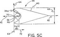
また、本発明は、図5A〜図5Dに示すように、展開長さが短いという有利な特徴を有する。本発明の短い展開距離は、ループ状ストラットと、支持ストラットをフィルター開口の面内に実質的に配置されている支持ワイヤに接続している中央カラーによるものである。特定の用途の必要に応じて、ループ状ストラットを、開口のわずかに上流に、又は開口のわずかに下流にフィルターフレーム要素自体の内部に向くように、フィルター要素の開口の面内に直接展開されるように構成できる。図5Aに、近位端43及び遠位端45を有する未拘束状態の本発明の塞栓フィルター30を示す。フィルター要素40は、x軸62及びy軸64を有する面を規定するフィルター「開口」60を有している。スカロップ41を備えたフィルター開口について、開口軸62及び64を、スカロップ41の最近位端に位置させる。図示されている開口面は、支持ワイヤ36及び縦軸42に直交している。したがって、2つの軸62、64は、フィルター開口60の面を規定している。本発明のループ状ストラット34は、しっかりと固定されるか又は摺動可能な手段を介して支持ワイヤ36のアタッチメント点38で取付けられた中央カラー46上に接合されている。 Moreover, as shown in FIGS. 5A to 5D, the present invention has an advantageous feature that the development length is short. The short deployment distance of the present invention is due to the looped struts and the central collar connecting the support struts to a support wire that is substantially disposed in the plane of the filter opening. Depending on the needs of a particular application, the loop struts can be deployed directly in the plane of the filter element opening so that it faces the interior of the filter frame element itself slightly upstream of the opening or slightly downstream of the opening. Can be configured. FIG. 5A shows the
図5Bに、フィルター開口60、y軸64及び縦軸42を有するフィルター要素40を示す。軸64は、フィルター開口の面の「側面図」である。軸42及び64は、点70で交差する。したがって、点70は、フィルター開口の面上にある。明確にするために、縦軸42上の点又は位置は、点が矢印で示されている縦方向72におけるフィルター要素内にある場合、フィルター開口の面から「遠位オフセット」しているとみなされる。逆に、縦軸42上の点又は位置は、点が矢印で示されている縦方向74におけるフィルター要素の外側にある場合、フィルター開口の面から「近位オフセット」しているとみなされる。 FIG. 5B shows a
図5Cは、ループ状支持ストラット34と、支持ワイヤにしっかりと固定され且つフィルター開口64の面から遠位オフセットしている支持ワイヤアタッチメント点38を有する本発明の中央カラー46を示す。図では、支持ワイヤアタッチメント点38が、遠位方向72におけるフィルター要素40内に位置している。アタッチメント点のオフセットの大きさは、要素80として示されている。 FIG. 5C shows the
図5Dは、ループ状支持ストラット34と、支持ワイヤにしっかりと固定され且つフィルター開口64の面から近位オフセットしている支持ワイヤアタッチメント点38を有する本発明の中央カラー46を示す。図では、支持ワイヤアタッチメント点38が、近位方向74におけるフィルター要素40の外に位置している。アタッチメント点のオフセットの大きさは、アイテム82として示されている。 FIG. 5D shows the
支持ワイヤアタッチメント点とフィルター開口64の面との間のオフセットの方向とともに、オフセットの相対的大きさは、ストラットアタッチメント点オフセットを未拘束直径44により割って得られた「オフセット比」により表すことができる。例えば、ストラットアタッチメント点オフセット4mm及び未拘束直径10mmを有するフィルターの比は、0.4である。この比を、フィルター開口の面に遠位オフセット又は近位オフセットした支持ワイヤアタッチメント点に対するストラットについて適用できる。比が「ゼロ」であることは、オフセットなしである。換言すれば、アタッチメント点が、フィルター開口の面にある。 Along with the direction of the offset between the support wire attachment point and the face of the
本発明の塞栓フィルターの遠位オフセット比(アタッチメント点オフセットを未拘束直径により割って得た)は、約0〜約1であることができ、好ましくは約0〜約0.7、最も好ましくは約0.2〜約0.5である。これらの遠位オフセット比は、フィルター要素内に配置された支持ワイヤアタッチメントに対するストラット/カラーに反映される。同様に、本発明の塞栓フィルターは、近位オフセット比を有することができ、フィルター要素の外側に配置された支持ワイヤアタッチメントに対するストラット/カラーに反映される。これらの構成において、本発明の塞栓フィルターのオフセット比(アタッチメント点オフセットを未拘束直径により割って得た)は、約0〜約1の範囲であることができる。 The distal offset ratio (obtained by dividing the attachment point offset by the unconstrained diameter) of the embolic filter of the present invention can be from about 0 to about 1, preferably from about 0 to about 0.7, most preferably About 0.2 to about 0.5. These distal offset ratios are reflected in struts / collars for support wire attachments located within the filter element. Similarly, the embolic filter of the present invention can have a proximal offset ratio and is reflected in the strut / collar for the support wire attachment located outside the filter element. In these configurations, the offset ratio (obtained by dividing the attachment point offset by the unconstrained diameter) of the embolic filter of the present invention can range from about 0 to about 1.
本発明の装置は、中央カラー対支持ワイヤアタッチメント点とは顕著に異なるストラット対中央カラーアタッチメント点で構成できる。これらの構成では、次に、両方のアタッチメント点を、ストラットに最も近接している支持ワイヤ上の点に近似させる。 The device of the present invention can be constructed with strut-to-center color attachment points that are significantly different from the center-collar-to-support wire attachment points. In these configurations, both attachment points are then approximated to the point on the support wire closest to the strut.
本発明のループ状支持ストラットにより、短展開長さが可能となるため、曲がりくねった容器内でのナビゲーションが向上し、血管側枝付近の展開が可能である。「短展開長さ」の特徴を定量化するために、装置を、以下で定義する5つの比のうちの少なくとも一つにより定義する必要がある。 The loop-shaped support strut of the present invention enables a short deployment length, so that navigation within a tortuous container is improved and deployment near the side branch of the blood vessel is possible. In order to quantify the “short deployment length” feature, the device needs to be defined by at least one of the five ratios defined below.
フィルターの配置長さは、展開長さを、フィルターの未拘束直径により割って得た第一比により表すことができる。図6Aに、フィルター要素40、ループ状ストラット34、ストラット/カラー対支持ワイヤアタッチメント点38(フィルター要素の外側に位置)及び未拘束直径44を備えた本発明の塞栓フィルター30を示す。図では、ループ状ストラット34及びアタッチメント点38を含む展開長さ84が示されている。 The arrangement length of the filter can be represented by a first ratio obtained by dividing the developed length by the unconstrained diameter of the filter. 6A shows an
図6Bは、フィルター要素40、ループ状ストラット34a、ストラット/カラー対支持ワイヤアタッチメント点38(フィルター要素内に位置)及び未拘束直径44を備えている本発明の塞栓フィルター30を示す。図では、フィルター要素の対向端を基準とし、ループ状ストラット34a又はアタッチメント点38を含まない配置長さ86が示されている。 FIG. 6B shows an
本発明の塞栓フィルターは、展開長さ84、86をフィルター未拘束直径44により割って得た比が約0.5〜約7、好ましくは約1〜約5、最も好ましくは約2〜約4であることができる。 The embolic filter of the present invention has a ratio of about 0.5 to about 7, preferably about 1 to about 5, most preferably about 2 to about 4, obtained by dividing the deployed
フィルター展開長さ又はフットプリントの同様なものが、フレームの展開長さ(フィルター要素を含まない)をフレームの未拘束直径により割って得た第二比で表される。図6Cは、フィルター支持部32及びループ状ストラット34、ストラット/カラー対支持ワイヤアタッチメント点38(フィルター要素40の外側に位置)及び未拘束フレーム直径44を備えた本発明の塞栓フィルターフレームを示す。図では、フィルター要素40を含まないフレーム展開長さ87が示されている。 A similar filter deployed length or footprint is represented by a second ratio obtained by dividing the deployed length of the frame (not including the filter element) by the unconstrained diameter of the frame. FIG. 6C shows an embolic filter frame of the present invention with
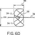
図6Dは、フィルター支持部32とループ状ストラット34、ストラット/カラー対支持ワイヤアタッチメント点38(フィルター要素40内に位置)及び未拘束直径44を備えている本発明の塞栓フィルターフレームである。図では、フィルター要素40を含まないフレーム展開長さ88が示されている。 FIG. 6D is an embolic filter frame of the present invention having a
本発明の塞栓フィルターは、フレーム展開長さ87、88をフレーム未拘束直径44により割って得た比が約0.1〜約7、好ましくは約0.3〜約2、最も好ましくは約0.5〜約1であることができる。 The embolic filter of the present invention has a ratio of about 0.1 to about 7, preferably about 0.3 to about 2, and most preferably about 0, obtained by dividing the
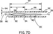
本発明のループ状ストラットのさらなる利点に、図7A〜7Dに示すような塞栓フィルターのデリバリの面がある。本発明のループ状支持ストラットを引張ったときに、細長くなり、コンパクトで実質的に直線状の形態をとる。デリバリカテーテル又は他の拘束手段によりこの直線状態に拘束された状態では、支持ストラットによっては、半径方向拘束手段には相対的にほとんどの力が加わらないので、半径方向の拘束手段は極めて薄く及び/又はデリケートなものでよい。したがって、総デリバリプロファイル及び剛さが、従来の塞栓フィルター装置について必要とされるものよりも減少する。デリバリカテーテルの拘束が展開中に除去されると、本発明のストラットが自然にオープンし、ループ形態をとり、高度の力が容器壁にかかり、フィルター対容器壁シールが向上する。 An additional advantage of the loop struts of the present invention is the embolic filter delivery aspect as shown in FIGS. When the loop support struts of the present invention are pulled, they become elongated, compact and take a substantially linear form. When restrained in this linear state by a delivery catheter or other restraining means, the radial restraining means is very thin and / or relatively little force is applied to the radial restraining means, depending on the support struts. Or it may be delicate. Thus, the total delivery profile and stiffness is reduced from that required for conventional embolic filter devices. When the delivery catheter restraint is removed during deployment, the struts of the present invention open naturally, take a loop configuration, apply high forces to the container wall, and improve the filter-to-container wall seal.
図7Aは、中央カラー46に取付けられたループ状ストラット34を有する本発明の塞栓フィルター30である。中央カラーは、支持ワイヤ36に取付けられている。支持ストラットは、外側に放射状に広がり、フィルター支持部32を有するフレームと一体(又は接合)とされている。フィルター要素40は、フィルター支持部32に取付けられている。 FIG. 7A is an
張力90を支持ワイヤ36及びフィルター要素40にかけると、ループ状ストラット34が弾性的に変形して、図7Bに示す形態となる。さらに張力90をかけると、塞栓フィルター30とループ状ストラット34は、ループ状ストラットが、図7Cに示すような実質的に直線的又は真っ直ぐな形態となるまで長くなる。細長い状態では、塞栓フィルター30をデリバリカテーテルに挿入できるか、又はシースに引っ込ませることができる。図7Dは、本発明の細長塞栓フィルター30を示している。この細長塞栓フィルター30は、デリバリカテーテル92において拘束されている実質的に直線状の形態のループ状ストラット34を備えている。細長いループ状ストラットによりデリバリカテーテルに加えられた小さい力により、比較的薄いカテーテル壁94を使用するのが容易となる。拘束デリバリカテーテルをフィルター展開中に除去すると、本発明のループ状ストラットが自然にオープンし、自然にか、又は支持ワイヤ及び/又はデリバリカテーテルの操作により図4及び図7Aに示す形態をとる。 When
容器内のデリバリの間、本発明の塞栓フィルターのストラット34は、図7Dに示すように「実質的に直線状」形態に拘束される。この実質的に直線状の形態では、中央支持カラー46(又はストラット対支持ワイヤアタッチメント点38)は、フィルター要素40の外側に位置している。また、中央支持カラー46は、細長く且つ実質的に直線状の支持ストラット34によりフィルター要素40から分離される。しかしながら、適切に展開されると、中央支持カラー46(又はストラット対支持ワイヤアタッチメント点38)は、図7Aに示すようにフィルター要素40内に位置する。したがって、中央支持カラー46(又はストラット対支持ワイヤアタッチメント点38)は、展開中フィルター要素に対して移動又は変形する。本発明の典型的なフィルターは、拘束されたフィルター要素96の長さの少なくとも1/2に等しい相対的な変形(支持カラー対フィルター要素)を受ける(図7Dに示すように)。 During delivery within the container, the
また、図7Dには、本発明の塞栓フィルターの総拘束デリバリ長さ97が示されている。本発明の塞栓フィルターは、総拘束デリバリ長さ97を未拘束長さにより割って得られた第三比を有することができる。本発明では、この第三比は、約1、約2、約2.5、約3、約3.5又はそれ以上であることができる。未拘束長さは、長さ84(図6A)又は長さ86(図6B)により定義される。 Also shown in FIG. 7D is the total
同様に、本発明の塞栓フィルターは、総拘束フレームデリバリ長さ98を未拘束フレーム長さにより割って得られた第四比を有することができる。本発明では、この第四比は、約2、約2.5、約3、約3.5又はそれ以上であることができる。未拘束フレーム長さは、長さ87(図6C)又は長さ88(図6D)により定義される。 Similarly, the embolic filter of the present invention can have a fourth ratio obtained by dividing the total constrained
短展開長さに関する第五比は、ストラット拘束デリバリ長さをストラット未拘束展開長さにより割って得たものである。ストラット拘束デリバリ長さは、図7Dに示すように、フィルター支持部32を含まない、フレームのストラット部34の長さとして定義される。したがって、ストラット拘束デリバリ長さは、図7Dにおける総フレーム長さ98の一部分である。ストラット未拘束長さは、フィルター支持部32の長さを含まない、図6C及び図6Dに示すような未拘束ストラット34aの長さとして定義される。本発明のフィルターフレームは、ストラット拘束デリバリ長さをストラット未拘束展開長さにより割って得た比が約2、約3、約4、約5、約6、約7又はそれ以上であることができる。本発明のフィルターフレームは、好ましくは、ストラット拘束デリバリ長さをストラット未拘束展開長さにより割って得た比が約3、約3.5、約4、約4.5若しくは約5又はそれ以上である。ストラット拘束デリバリ長さをストラット未拘束展開長さにより割って得た比は、最も好ましくは、約3、約3.3、約3.6若しくは約4又はそれ以上である。 The fifth ratio for the short deployed length is obtained by dividing the strut restrained delivery length by the strut unconstrained deployed length. The strut restraint delivery length is defined as the length of the
本発明の塞栓フィルターは、種々の一般的な方法及びプロセスを用いて製造できる。例えば、ループ状ストラットを備えた塞栓フィルターフレームは、適切な弾性及び剛さを有する生体適合性材料から加工できる。例えば、ニチノール、ステンレス鋼、チタン及びポリマーを、適用可能な材料として用いることができる。ループ状ストラットを備えた前駆体フレームは、平面シート形態で加工でき、ロール状とし、それ自体に付着して本発明のフレームを形成してもよい。別法として、円筒状管を切断し、拡張するか、又は切断し、圧縮して本発明のフレームを形成してもよい。切断プロセスとして、レーザー、スタンピング、エッチング、ミルカッティング、ウオータージェット、放電加工又は他の好適なプロセスを挙げることができる。 The embolic filter of the present invention can be manufactured using a variety of common methods and processes. For example, an embolic filter frame with looped struts can be fabricated from a biocompatible material with appropriate elasticity and stiffness. For example, nitinol, stainless steel, titanium and polymer can be used as applicable materials. The precursor frame with looped struts can be processed in the form of a flat sheet, can be rolled and attached to itself to form the frame of the present invention. Alternatively, the cylindrical tube may be cut, expanded, or cut and compressed to form the frame of the present invention. The cutting process can include laser, stamping, etching, mill cutting, water jet, electrical discharge machining or other suitable processes.
本発明のループ状ストラットとの関連で使用されるフィルター要素又は部材は、種々の一般的な材料、方法及びプロセスを用いて製造できる。好適な生体適合材料には、金属箔若しくはメッシュ、又は種々のポリマー、例えば、フルオロポリマー、例えば、ポリテトラフルオロエチレンから形成されたシート若しくはメッシュなどがあるが、これらには限定されない。フィルター部材は、成形、キャスト、フォーミングにより形成したり、又は種々の好適な材料を接合することにより加工できる。 The filter elements or members used in connection with the loop struts of the present invention can be manufactured using a variety of common materials, methods and processes. Suitable biocompatible materials include, but are not limited to, metal foils or meshes or various polymers such as sheets or meshes formed from fluoropolymers such as polytetrafluoroethylene. The filter member can be formed by molding, casting, forming, or processed by joining various suitable materials.
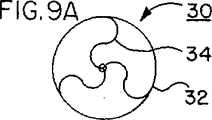
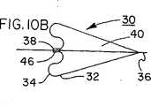
図8〜図12は、本発明のループ状ストラットの種々の別の実施態様を示す(しかしながら、これらには限定されない)。図8A及び図8Bは、好ましいループ状ストラットの形態34を有する塞栓フィルター30を示す。本発明の好ましいストラット34は、直交する2本の軸に沿ってみたときに、ループの形状又はプロファイルを有することができる。したがって、ストラット34は、2つの直交図の投影においてループ形態をとる。 8-12 illustrate various alternative embodiments of the looped struts of the present invention (but are not limited thereto). 8A and 8B show an
本発明の別のストラットの形態では、異なる軸の組み合わせに沿ってみたとき、又は単一の軸に沿ってみたとき、ループ状であることができる。例えば、図9A及び図9Bは、図8A及び図8Bと類似の図であるが、別のループ状ストラット形態を示しており、別のストラット34は、単一軸に沿ってみたときのみに実質的にループ状である。図では、ストラット34は、端面図(図9A)においてループ状であり、側面図(図9B)において実質的に直線状である。 In another strut configuration of the present invention, it can be looped when viewed along a combination of different axes or when viewed along a single axis. For example, FIGS. 9A and 9B are similar to FIGS. 8A and 8B, but show another looped strut configuration, where another
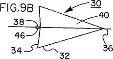
別法として、本発明のストラットは、端部からみたときには実質的に直線状であり、例えば、側面からみたときにはループ状であることができる。この形態を、図10A及び図10Bに示す。図10A及び図10Bは、端部(図10A)からみたときには実質的に直線状であり、側面(図10B)からみたときにはループ形態である別のストラット34を示す。 Alternatively, the struts of the present invention can be substantially straight when viewed from the end, for example, can be looped when viewed from the side. This form is shown in FIGS. 10A and 10B. 10A and 10B show another
本発明のループ状支持ストラットは、約90度超(図3Cにより定義されている)、約120度超、約180度超、約240度超、又はそれ以上の曲げを設けて構成してもよい。例えば、約200度超の曲げを有する本発明のループ状ストラットを、図11Aに示す。図には、約200度以上の「らせん状」の曲げを有するループ状支持ストラット34を備えた塞栓フィルター30が示されている。また、ストラット34は、別の軸、この場合、図11Bに示すような側面図でみたときにループ状であってもよい。したがって、本発明のループ状支持ストラットは、異なる観測面に投影したときに異なる「ループ」形態を有することができる。 The looped support struts of the present invention may be configured with bends greater than about 90 degrees (as defined by FIG. 3C), greater than about 120 degrees, greater than about 180 degrees, greater than about 240 degrees, or more. Good. For example, a looped strut of the present invention having a bend greater than about 200 degrees is shown in FIG. 11A. Illustrated is an
図8〜図11に、3つのループ状支持ストラットを備えた塞栓フィルターを示す。このフィルターでは、支持ワイヤアタッチメント点38及び中央支持カラー46が、図5A及び図5Bについて上記したように、実質的にフィルター要素内にある。本発明の塞栓フィルターフレームは、2、3、4、5、6、7、8又はそれ以上のループ状支持ストラットを有することができる。種々の複数のストラットの形態が、図12A〜図12Fに示されている。 8 to 11 show an embolic filter having three loop-shaped support struts. In this filter, the support
図12Aは、3つのループ状ストラット34を備えた本発明の塞栓フィルターの端面図である。 FIG. 12A is an end view of the embolic filter of the present invention with three looped struts 34.
図12Bは、4つのループ状ストラット34を備えた本発明の塞栓フィルターの端面図である。 FIG. 12B is an end view of the embolic filter of the present invention with four looped
図12Cは、5つのループ状ストラット34を備えた本発明の塞栓フィルターの端面図である。 FIG. 12C is an end view of the embolic filter of the present invention with five looped struts 34.
図12Dは、6つのループ状ストラット34を備えた本発明の塞栓フィルターの端面図である。 FIG. 12D is an end view of the embolic filter of the present invention with six looped struts 34.
図12Eは、7つのループ状ストラット34を備えた本発明の塞栓フィルターの端面図である。 FIG. 12E is an end view of the embolic filter of the present invention with seven looped struts 34.
図12Fは、8つのループ状ストラット34を備えた本発明の塞栓フィルターの端面図である。 FIG. 12F is an end view of the embolic filter of the present invention with eight looped struts 34.
本発明の塞栓フィルターフレームのさらなる機能的特徴を、図13に示す。図13は、ループ状支持ストラット34、フィルター要素支持体32に取付けられたフィルター要素40、中央カラー46及び支持ワイヤ36を備えた塞栓フィルター30を示す。小さい容器(すなわち、フィルターの弛緩した完全配置直径よりも小さい容器)内に展開したとき、圧縮負荷100がフレームに加わり、フレームにより容器に加えられた半径方向力に対抗する。圧縮負荷100により、フレーム部、この場合フィルター要素支持部32が、アイテム102により示されるように外側にたわむ。たわみ102により、フィルター要素40と容器壁との間のシールが改善され、塞栓が不注意で通過してしまうことを減少できる。容器壁にさらなる負荷をかけても、フィルターと容器との間の相対的な移動により生じる「血管外傷」の可能性及び曲がった血管の部分に展開したときの抵抗を減少させることができる。 Additional functional features of the embolic filter frame of the present invention are shown in FIG. FIG. 13 shows an
図14は、ループ状ストラット34及び簡略化されたフィルター支持部(図2に示す細長フィルター支持部32とは異なる)を備えたフレームの別の形態を示す。図には、支持ワイヤ36と、本発明の6つのループ状支持ストラット34の端部に直接取付けられたフィルター要素40が示されている。支持ストラット34は、フィルター要素40のアタッチメント点103に取付けられている。この実施態様におけるストラット34の長さ及び形状は、ストラット34をフィルター要素上の異なる点に接合できるようにしたり、ストラット34の部分的な長さに沿ってフィルター要素40を接合できるように異ならせることができる。 FIG. 14 shows another form of frame with looped
本発明のフィルターフレームのさらなる特徴に、「ロッキングパイラー」又は「中心をはずれた固定クランプ」と類似の、拘束された直線状状態から、「固定」及び逆転した状態へのループ状ストラットの「自然」変形がある。逆転すると、ループ状ストラットは、安定な短い長さのループ状形態を維持する。拘束された直線状に戻すには、張力をかける必要がある。 A further feature of the filter frame of the present invention is the “natural” nature of the looped struts from a constrained linear state to a “fixed” and reversed state, similar to a “rocking pillar” or “off-centered fixed clamp”. There is a deformation. When reversed, the looped struts maintain a stable short length looped configuration. To return to the constrained straight line, it is necessary to apply tension.
本発明に言及及び本発明に関しての用語「支持ワイヤ」(例えば、図1における要素36)は、中実又は中空支持ワイヤを有していてもよいし、又は他の管状物品であって、そこを通過して設けられた少なくとも一つの連続管腔を備えたものを有していてもよい。本発明で使用するのに好適な支持ワイヤには、ガイドワイヤなどがあるが、これには限定されない。 The term “support wire” in reference to and in connection with the present invention (eg,
本発明のフィルターは、種々の物品内に展開、例えば、動物用容器、カテーテル、パイプ、ダクト、流体管、チューブ、ホース、物質移動管、貯蔵容器、ポンプ、バルブ及び他の流体容器(これらには限定されない)内の濾過用途に使用されるように構成できる。濾過できる流体としては、ガス、液体、血漿及び流動性固体又は粒状混合物などがある。流体は、本発明のフィルターを横断して流れてもよいし、又はフィルターを、流体を通して引くか、さもなければ搬送してもよい。本発明のフィルターは、一般的に円形のプロファイル(端面からみたとき)には限定されず、展開したときに、楕円形、三角形、正方形、多角形又は他のプロファイルを有していてもよい。また、本発明のフィルターは、他の装置、例えば、診断、可視化、治療器具又は他のフィルターと組み合わせたり、「連動」させたり、又は連結させたりすることができる。また、本発明のストラットの形態を、非濾過装置、例えば、容器閉塞器、留置診断機器、治療機器又は可視化装置に組み込むこともできる。 The filter of the present invention can be deployed in a variety of articles, such as animal containers, catheters, pipes, ducts, fluid tubes, tubes, hoses, mass transfer tubes, storage containers, pumps, valves and other fluid containers. Can be configured for use in filtration applications within (but not limited to). Fluids that can be filtered include gases, liquids, plasma, and flowable solids or particulate mixtures. The fluid may flow across the filter of the present invention, or the filter may be drawn through or otherwise conveyed through the fluid. The filter of the present invention is not limited to a generally circular profile (when viewed from the end face), and may have an elliptical, triangular, square, polygonal or other profile when unfolded. Also, the filter of the present invention can be combined, “interlocked”, or coupled with other devices, such as diagnostic, visualization, therapeutic instruments or other filters. The strut configuration of the present invention can also be incorporated into non-filtration devices such as container occluders, indwelling diagnostic devices, treatment devices or visualization devices.
以下、本発明の装置及び製造方法を実施例により説明するが、本発明の範囲はこれらには限定されない。 Hereinafter, although the apparatus and manufacturing method of this invention are demonstrated by an Example, the scope of the present invention is not limited to these.
例1
図15に示すように、壁厚約0.09mmの0.9mmニチノールチューブ104(カリフォルニア州サンノゼにあるSMA社製)を、レーザー(イリノイ州ウァキガンにあるLaserage Technologies社)により切断して、単一の波形一体の6頂点リングのフレーム形態とした。フレームは、各遠位頂点に放射線不透過性マーカーハウジング106、並びに各近位頂点108から延び、未切断母材の「カラー」46における対向端で収束している係留又はストラット要素34を備えているものであった。次に、このフレームを、グリットブラスト機(モデルMB1000、カリフォルニア州バーバンクにあるComco社製)により、20ミクロンシリコンカーバイド媒体を用いて30psiで軽くグリットブラストした。次に、フレームを、機能サイズ約6mmとなるまで、徐々にテーパーマンドレルに滑りこませた。Example 1
As shown in FIG. 15, a 0.9 mm Nitinol tube 104 (manufactured by SMA, San Jose, Calif.) Having a wall thickness of about 0.09 mm was cut with a laser (Laserage Technologies, Waukegan, Ill.) To produce a single piece. The corrugated 6-vertex ring frame was used. The frame comprises a
次に、フレーム及びマンドレルを、空気対流オーブン(英国シェフィールドにあるCarbolite社)により初期熱処理に付して初期テーパー(コニカル)形態に形状寸法を固定した。フレームを、周囲温度水で急冷し、マンドレルから取り出して、非反転フレームを得た。 The frame and mandrel were then subjected to an initial heat treatment in an air convection oven (Carbolite, Sheffield, UK) to fix the geometry in the initial tapered (conical) form. The frame was quenched with ambient temperature water and removed from the mandrel to obtain a non-inverted frame.
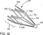
図16に、非反転フレーム110を示す。この非反転フレーム110は、支持ストラット34、中央カラー46、頂点108及び放射線不透過性マーカーハウジング106を備えている。頂点108に対して遠位のフレーム部は、フィルター要素支持部32を形成している。次に、フレームを、係留要素のそれら自体の反転をさせながらフレームの外側を拘束するように設計された第二マンドレル上に配置した。適切な形態に拘束されたら、ツーリング及びフレームを、第二熱処理に付して、最終フレーム形状寸法とし且つ適切な温度にニチノール移行させた。得られた反転フレームを、図17に示す。 FIG. 16 shows a non-inverted frame 110. The non-inverted frame 110 includes a
図17に、反転フレーム112を示す。この反転フレーム112は、6つのループ状支持ストラット34a、頂点108、放射線不透過性ハウジング106及び一体中央カラー46を備えている。頂点108に遠位のフレーム部は、フィルター要素支持部32を構成する。 FIG. 17 shows the
当業者には、フィルターフレーム材料(単一又は複数)、寸法、形状寸法及び/又は処理の差異は、全て、異なる望ましい性質の別の実施態様とすることができることは、理解できるところであろう。例えば、頂点108に対する中央カラー46の相対的な位置は、図5C及び図5Dにしたがって変更できる。 Those skilled in the art will appreciate that differences in filter frame material (s), dimensions, geometry and / or processing can all be alternative embodiments of different desirable properties. For example, the relative position of the
次に、フレーム(ここでは機能的サイズ及び好ましい形状寸法)に、フッ素化エチレンプロピレン(FEP)粉末(例えば、FEP5101、デラウエア州ウィルミントンにあるDuPont社製)を薄くコーティングした。この場合、まず粉末を「クラウド」に混合した後、粉末をキッチンブレンダー(Hamilton Beach Blendmaster)中で攪拌し、フレームをブレンダーに約5秒間(FEPがフレームの表面上に堆積するのに十分な時間)降下して入れた。FEP粉末をコーティングしたフレームを、空気対流オーブン(Grieve Oven、イリノイ州ラウンドレイクにあるThe Grieve社製)中、320℃で約1分間保持した後、室温まで空冷した。 The frame (here, functional size and preferred geometry) was then thinly coated with fluorinated ethylene propylene (FEP) powder (eg, FEP 5101, DuPont, Wilmington, Del.). In this case, the powder is first mixed into the “cloud” and then the powder is stirred in a kitchen blender (Hamilton Beach Blendmaster) and the frame is left in the blender for about 5 seconds (enough time for the FEP to deposit on the surface of the frame). ) Descent and put in. The frame coated with FEP powder was held at 320 ° C. for about 1 minute in an air convection oven (Grieve Oven, The Gliveve, Round Lake, Ill.) And then air cooled to room temperature.
10ワットCO2レーザーを用いて1層の薄ポリテトラフルオロエチレン(PTFE)膜をレーザーせん孔することにより、典型的な濾過媒体を作製した。膜厚は、約0.0002“(0.005mm)であり、引張り強度は、第一方向では約49000psi(約340KPa)であり、第二方向(第一方向に対して垂直)では約17000psi(約120KPa)であった。引張強度の測定は、負荷速度200mm/分、ジョー間隔1”(2.5cm)で実施した。膜の密度は、約2.14g/cm3であった。レーザーパワー及びシャッター時間のパラメータを調整して、レーザーが、膜に均一な直径0.004”(0.1mm)の孔を連続して形成できるようにした。次に、孔パターンの形状寸法を調整して、パターン全体を通じて、孔サイズが均一で、孔間隔が均一で、強度が均一であるパターンを形成した。次に、この有孔パターンをそれ自体に重ね、局部加熱ソース(Weberはんだごて、EC2002M(カリフォルニア州サンタフェスプリングスにあるMcMaster Carr社製)を用いて熱シールして、円錐状のパターンとした。次に、円錐状フラットパターンを、はさみでトリミングし、反転させ、FEP粉末をコーティングしたNiTiフレームに取り付け、局部的に加熱させることにより結合させた(熱により、フレーム上のFEPコーティングが再融解し、フィルターサックの表面上を流れることにより、生体適合性熱可塑性接着がなされる)。A typical filtration media was made by laser drilling a layer of thin polytetrafluoroethylene (PTFE) membrane using a 10 watt CO2 laser. The film thickness is about 0.0002 "(0.005 mm), and the tensile strength is about 49000 psi (about 340 KPa) in the first direction and about 17000 psi in the second direction (perpendicular to the first direction). The tensile strength was measured at a load speed of 200 mm / min and a jaw distance of 1 ″ (2.5 cm). The density of the film was about 2.14 g / cm3 . The laser power and shutter time parameters were adjusted to allow the laser to continuously form holes with a uniform diameter of 0.004 "(0.1 mm) in the film. Adjustments were made to form a pattern with uniform hole size, uniform hole spacing and uniform strength throughout the pattern, which was then superimposed on itself to produce a local heating source (Weber soldering iron). And then heat sealed using EC2002M (McMaster Carr, Santa Fe Springs, Calif.) To form a conical pattern, which was then trimmed with scissors, inverted, and the FEP powder Attached to the coated NiTi frame and bonded by locally heating (by heat, the frame The upper FEP coating remelts and flows over the surface of the filter sack, resulting in a biocompatible thermoplastic bond).
次に、ガイドワイヤコンポーネントを、フレームのカラー端部に挿入し、少量の瞬間接着剤(Loctite401、コネチカット州ロッキーヒルにあるLoctitie社製)を適用し、乾燥して接着し、ガイドワイヤからフレームカラーの外径(OD)までスムーズに移行するようにした。当業者には、ガイドワイヤへのフィルターの取付けが、接着、溶接、はんだ付け、ろう付け、これらの組み合わせ又は多数の他の方法により可能であることが分かるであろう。 Next, insert the guidewire component into the collar end of the frame, apply a small amount of instantaneous adhesive (Loctite 401, Loctiti, Rocky Hill, Conn.), Dry and bond, Smooth transition to outer diameter (OD). One skilled in the art will appreciate that the filter can be attached to the guidewire by gluing, welding, soldering, brazing, combinations thereof, or many other methods.
得られた塞栓フィルターは、図1等に示し且つそれらに関連して説明したとおりである。 The obtained embolic filter is as shown in FIG. 1 etc. and described in relation thereto.
本発明のさらなる実施態様を、図18A〜図18Cに示す。この実施態様によれば、フィルターアセンブリ30は、支持ワイヤ36に摺動可能に取付けられたフレーム31を備えている。この取付けは、種々の手段、例えば、支持ワイヤ36よりもわずかに大きいカラー46を設けて、カラーが使用中に支持ワイヤに対して移動できるようにすることによりおこなうことができる。ストップ114a、114bを、支持ワイヤ36上に設けて、フィルターアセンブリ30と支持ワイヤ36との間の相対的な移動範囲を制限する。このように構成されたフィルターアセンブリ30は、支持ワイヤに対して非常に優れた縦方向コンプライアンスを有しており、支持ワイヤは、縦方向又は回転移動をフィルターアセンブリに移行させることなく、ストップ114の間で自由に動くことができる。ストップ114に対するフィルターアセンブリ30のフルレンジの近位及び遠位移動を、図18B及び図18Cに示す。 A further embodiment of the present invention is shown in FIGS. 18A-18C. According to this embodiment, the
本発明の特定の実施態様を、本明細書において例示し、説明した。本発明は、このような例示及び説明には限定されない。また、変更及び修正、添付の特許請求の範囲内で本発明の一部分として組み込まれ且つ具体化できることは明らかである。 Particular embodiments of the present invention have been illustrated and described herein. The present invention is not limited to such illustrations and descriptions. It will be apparent that changes and modifications may be incorporated and embodied as part of the present invention within the scope of the appended claims.
Claims (4)
Translated fromJapanese支持ワイヤと;
支持ワイヤの周りに円周方向に配置されたフィルター支持部と、前記支持ワイヤに取り付けられた複数の支持ストラットとを備えた塞栓フィルターフレームと;
外縁を有するフィルター要素であって該外縁が前記フィルター支持部に取り付けられたフィルター要素とを備え、
前記支持ストラットが前記支持ワイヤから放射状に延びており;
少なくとも一つの支持ストラットが、展開された状態で引張状態にないときにはループ状の形態をしている塞栓フィルター。An embolic filter,
A support wire;
An embolic filter frame comprisinga filter supportdisposed circumferentially around the support wire and a plurality of support struts attached to the support wire;
A filter element having an outer edge, whereinthe outer edge is attached to the filter support,
The support struts extend radially from the support wire;
An embolic filter in which at least one support strut is in the form of a loop when deployed and not in tension.
Applications Claiming Priority (2)
| Application Number | Priority Date | Filing Date | Title |
|---|---|---|---|
| US10/273,859US20040093012A1 (en) | 2002-10-17 | 2002-10-17 | Embolic filter frame having looped support strut elements |
| PCT/US2003/032962WO2004034884A2 (en) | 2002-10-17 | 2003-10-16 | Embolic filter frame having looped support strut elements |
Related Child Applications (1)
| Application Number | Title | Priority Date | Filing Date |
|---|---|---|---|
| JP2009285029ADivisionJP5065368B2 (en) | 2002-10-17 | 2009-12-16 | An embolic filter frame with looped support strut elements |
Publications (2)
| Publication Number | Publication Date |
|---|---|
| JP2006502808A JP2006502808A (en) | 2006-01-26 |
| JP4620465B2true JP4620465B2 (en) | 2011-01-26 |
Family
ID=32106464
Family Applications (4)
| Application Number | Title | Priority Date | Filing Date |
|---|---|---|---|
| JP2004545447AExpired - Fee RelatedJP4620465B2 (en) | 2002-10-17 | 2003-10-16 | An embolic filter frame with looped support strut elements |
| JP2009285029AExpired - Fee RelatedJP5065368B2 (en) | 2002-10-17 | 2009-12-16 | An embolic filter frame with looped support strut elements |
| JP2012138703AWithdrawnJP2012196515A (en) | 2002-10-17 | 2012-06-20 | Embolic filter frame having looped support strut elements |
| JP2015080006APendingJP2015163207A (en) | 2002-10-17 | 2015-04-09 | Embolic filter frame having loop-like support strut element |
Family Applications After (3)
| Application Number | Title | Priority Date | Filing Date |
|---|---|---|---|
| JP2009285029AExpired - Fee RelatedJP5065368B2 (en) | 2002-10-17 | 2009-12-16 | An embolic filter frame with looped support strut elements |
| JP2012138703AWithdrawnJP2012196515A (en) | 2002-10-17 | 2012-06-20 | Embolic filter frame having looped support strut elements |
| JP2015080006APendingJP2015163207A (en) | 2002-10-17 | 2015-04-09 | Embolic filter frame having loop-like support strut element |
Country Status (8)
| Country | Link |
|---|---|
| US (6) | US20040093012A1 (en) |
| EP (6) | EP2626105A1 (en) |
| JP (4) | JP4620465B2 (en) |
| AT (1) | ATE519519T1 (en) |
| AU (1) | AU2003301259A1 (en) |
| CA (1) | CA2502225C (en) |
| ES (2) | ES2555610T3 (en) |
| WO (1) | WO2004034884A2 (en) |
Families Citing this family (143)
| Publication number | Priority date | Publication date | Assignee | Title |
|---|---|---|---|---|
| US6402771B1 (en) | 1999-12-23 | 2002-06-11 | Guidant Endovascular Solutions | Snare |
| US6660021B1 (en) | 1999-12-23 | 2003-12-09 | Advanced Cardiovascular Systems, Inc. | Intravascular device and system |
| US6575997B1 (en) | 1999-12-23 | 2003-06-10 | Endovascular Technologies, Inc. | Embolic basket |
| US6695813B1 (en) | 1999-12-30 | 2004-02-24 | Advanced Cardiovascular Systems, Inc. | Embolic protection devices |
| US7918820B2 (en) | 1999-12-30 | 2011-04-05 | Advanced Cardiovascular Systems, Inc. | Device for, and method of, blocking emboli in vessels such as blood arteries |
| US6540722B1 (en) | 1999-12-30 | 2003-04-01 | Advanced Cardiovascular Systems, Inc. | Embolic protection devices |
| US6939362B2 (en)* | 2001-11-27 | 2005-09-06 | Advanced Cardiovascular Systems, Inc. | Offset proximal cage for embolic filtering devices |
| US6964670B1 (en) | 2000-07-13 | 2005-11-15 | Advanced Cardiovascular Systems, Inc. | Embolic protection guide wire |
| US6537294B1 (en) | 2000-10-17 | 2003-03-25 | Advanced Cardiovascular Systems, Inc. | Delivery systems for embolic filter devices |
| US6893451B2 (en) | 2000-11-09 | 2005-05-17 | Advanced Cardiovascular Systems, Inc. | Apparatus for capturing objects beyond an operative site utilizing a capture device delivered on a medical guide wire |
| US6506203B1 (en) | 2000-12-19 | 2003-01-14 | Advanced Cardiovascular Systems, Inc. | Low profile sheathless embolic protection system |
| US7044952B2 (en) | 2001-06-06 | 2006-05-16 | Sdgi Holdings, Inc. | Dynamic multilock anterior cervical plate system having non-detachably fastened and moveable segments |
| US7338510B2 (en) | 2001-06-29 | 2008-03-04 | Advanced Cardiovascular Systems, Inc. | Variable thickness embolic filtering devices and method of manufacturing the same |
| US6599307B1 (en) | 2001-06-29 | 2003-07-29 | Advanced Cardiovascular Systems, Inc. | Filter device for embolic protection systems |
| US6638294B1 (en) | 2001-08-30 | 2003-10-28 | Advanced Cardiovascular Systems, Inc. | Self furling umbrella frame for carotid filter |
| US6592606B2 (en) | 2001-08-31 | 2003-07-15 | Advanced Cardiovascular Systems, Inc. | Hinged short cage for an embolic protection device |
| US8262689B2 (en) | 2001-09-28 | 2012-09-11 | Advanced Cardiovascular Systems, Inc. | Embolic filtering devices |
| US7241304B2 (en)* | 2001-12-21 | 2007-07-10 | Advanced Cardiovascular Systems, Inc. | Flexible and conformable embolic filtering devices |
| US20030187495A1 (en) | 2002-04-01 | 2003-10-02 | Cully Edward H. | Endoluminal devices, embolic filters, methods of manufacture and use |
| US6887258B2 (en) | 2002-06-26 | 2005-05-03 | Advanced Cardiovascular Systems, Inc. | Embolic filtering devices for bifurcated vessels |
| US7331973B2 (en) | 2002-09-30 | 2008-02-19 | Avdanced Cardiovascular Systems, Inc. | Guide wire with embolic filtering attachment |
| US7252675B2 (en) | 2002-09-30 | 2007-08-07 | Advanced Cardiovascular, Inc. | Embolic filtering devices |
| US20040093012A1 (en) | 2002-10-17 | 2004-05-13 | Cully Edward H. | Embolic filter frame having looped support strut elements |
| US20040088000A1 (en) | 2002-10-31 | 2004-05-06 | Muller Paul F. | Single-wire expandable cages for embolic filtering devices |
| US20040147955A1 (en)* | 2003-01-28 | 2004-07-29 | Scimed Life Systems, Inc. | Embolic protection filter having an improved filter frame |
| US8591540B2 (en) | 2003-02-27 | 2013-11-26 | Abbott Cardiovascular Systems Inc. | Embolic filtering devices |
| US6969396B2 (en)* | 2003-05-07 | 2005-11-29 | Scimed Life Systems, Inc. | Filter membrane with increased surface area |
| US7892251B1 (en) | 2003-11-12 | 2011-02-22 | Advanced Cardiovascular Systems, Inc. | Component for delivering and locking a medical device to a guide wire |
| US7678129B1 (en) | 2004-03-19 | 2010-03-16 | Advanced Cardiovascular Systems, Inc. | Locking component for an embolic filter assembly |
| CA2758946C (en) | 2004-05-25 | 2014-10-21 | Tyco Healthcare Group Lp | Vascular stenting for aneurysms |
| US8617234B2 (en) | 2004-05-25 | 2013-12-31 | Covidien Lp | Flexible vascular occluding device |
| US20060206200A1 (en) | 2004-05-25 | 2006-09-14 | Chestnut Medical Technologies, Inc. | Flexible vascular occluding device |
| US8623067B2 (en) | 2004-05-25 | 2014-01-07 | Covidien Lp | Methods and apparatus for luminal stenting |
| CA2565106C (en)* | 2004-05-25 | 2013-11-05 | Chestnut Medical Technologies, Inc. | Flexible vascular occluding device |
| EP1858437B1 (en)* | 2004-09-17 | 2011-08-24 | Nitinol Development Corporation | Shape memory thin film embolic protection device |
| CA2580209C (en)* | 2004-09-17 | 2013-11-12 | Nitinol Development Corporation | Shape memory thin film embolic protection device with frame |
| WO2006042114A1 (en) | 2004-10-06 | 2006-04-20 | Cook, Inc. | Emboli capturing device having a coil and method for capturing emboli |
| US9707071B2 (en) | 2004-11-24 | 2017-07-18 | Contego Medical Llc | Percutaneous transluminal angioplasty device with integral embolic filter |
| US20060149312A1 (en)* | 2004-12-30 | 2006-07-06 | Edward Arguello | Distal protection device with improved wall apposition |
| US8945169B2 (en) | 2005-03-15 | 2015-02-03 | Cook Medical Technologies Llc | Embolic protection device |
| US8221446B2 (en) | 2005-03-15 | 2012-07-17 | Cook Medical Technologies | Embolic protection device |
| US9259305B2 (en) | 2005-03-31 | 2016-02-16 | Abbott Cardiovascular Systems Inc. | Guide wire locking mechanism for rapid exchange and other catheter systems |
| US20060229658A1 (en)* | 2005-04-07 | 2006-10-12 | Stivland Timothy M | Embolic protection filter with reduced landing zone |
| AU2005332044B2 (en) | 2005-05-25 | 2012-01-19 | Covidien Lp | System and method for delivering and deploying and occluding device within a vessel |
| US8187298B2 (en) | 2005-08-04 | 2012-05-29 | Cook Medical Technologies Llc | Embolic protection device having inflatable frame |
| US8377092B2 (en)* | 2005-09-16 | 2013-02-19 | Cook Medical Technologies Llc | Embolic protection device |
| US8632562B2 (en) | 2005-10-03 | 2014-01-21 | Cook Medical Technologies Llc | Embolic protection device |
| US8182508B2 (en) | 2005-10-04 | 2012-05-22 | Cook Medical Technologies Llc | Embolic protection device |
| US8252017B2 (en) | 2005-10-18 | 2012-08-28 | Cook Medical Technologies Llc | Invertible filter for embolic protection |
| US8216269B2 (en)* | 2005-11-02 | 2012-07-10 | Cook Medical Technologies Llc | Embolic protection device having reduced profile |
| US8152831B2 (en) | 2005-11-17 | 2012-04-10 | Cook Medical Technologies Llc | Foam embolic protection device |
| US8152833B2 (en) | 2006-02-22 | 2012-04-10 | Tyco Healthcare Group Lp | Embolic protection systems having radiopaque filter mesh |
| WO2007126931A2 (en) | 2006-03-31 | 2007-11-08 | Ev3 Inc. | Embolic protection devices having radiopaque markers |
| US8409238B2 (en)* | 2006-05-18 | 2013-04-02 | Boston Scientific Scimed, Inc. | Mini cams on support loop for vessel stabilization |
| US20080071307A1 (en) | 2006-09-19 | 2008-03-20 | Cook Incorporated | Apparatus and methods for in situ embolic protection |
| WO2008094827A1 (en) | 2007-02-02 | 2008-08-07 | Ev3 Inc. | Embolic protection devices having short landing zones |
| US9901434B2 (en) | 2007-02-27 | 2018-02-27 | Cook Medical Technologies Llc | Embolic protection device including a Z-stent waist band |
| US8216209B2 (en) | 2007-05-31 | 2012-07-10 | Abbott Cardiovascular Systems Inc. | Method and apparatus for delivering an agent to a kidney |
| US7867273B2 (en) | 2007-06-27 | 2011-01-11 | Abbott Laboratories | Endoprostheses for peripheral arteries and other body vessels |
| US8613753B2 (en) | 2007-08-31 | 2013-12-24 | BiO2 Medical, Inc. | Multi-lumen central access vena cava filter apparatus and method of using same |
| US8668712B2 (en) | 2007-08-31 | 2014-03-11 | BiO2 Medical, Inc. | Multi-lumen central access vena cava filter apparatus and method of using same |
| US8252018B2 (en) | 2007-09-14 | 2012-08-28 | Cook Medical Technologies Llc | Helical embolic protection device |
| US9138307B2 (en) | 2007-09-14 | 2015-09-22 | Cook Medical Technologies Llc | Expandable device for treatment of a stricture in a body vessel |
| US8419748B2 (en) | 2007-09-14 | 2013-04-16 | Cook Medical Technologies Llc | Helical thrombus removal device |
| US8052717B2 (en)* | 2008-07-14 | 2011-11-08 | Boston Scientific Scimed, Inc. | Embolic protection device |
| US8388644B2 (en) | 2008-12-29 | 2013-03-05 | Cook Medical Technologies Llc | Embolic protection device and method of use |
| US20100286722A1 (en)* | 2009-05-11 | 2010-11-11 | Intersect Partners, Llc | Temporary venous filter system |
| US20110054515A1 (en) | 2009-08-25 | 2011-03-03 | John Bridgeman | Device and method for occluding the left atrial appendage |
| US20110054593A1 (en)* | 2009-08-28 | 2011-03-03 | Boston Scientific Scimed, Inc. | Sheathless embolic protection device |
| US9211123B2 (en)* | 2009-12-31 | 2015-12-15 | Cook Medical Technologies Llc | Intraluminal occlusion devices and methods of blocking the entry of fluid into bodily passages |
| AU2011217844B2 (en) | 2010-02-18 | 2014-09-25 | BiO2 Medical, Inc. | Vena cava filter catheter and method |
| JP5642170B2 (en)* | 2010-06-03 | 2014-12-17 | 株式会社グツドマン | Medical device for embolus capture |
| US9005234B2 (en) | 2010-12-30 | 2015-04-14 | Cook Medical Technologies Llc | Occlusion device |
| US9744033B2 (en) | 2011-04-01 | 2017-08-29 | W.L. Gore & Associates, Inc. | Elastomeric leaflet for prosthetic heart valves |
| US10117765B2 (en) | 2011-06-14 | 2018-11-06 | W.L. Gore Associates, Inc | Apposition fiber for use in endoluminal deployment of expandable implants |
| US8608771B2 (en) | 2011-07-13 | 2013-12-17 | Cook Medical Technologies Llc | Vascular occlusion device with enhanced feedback |
| US9554806B2 (en) | 2011-09-16 | 2017-01-31 | W. L. Gore & Associates, Inc. | Occlusive devices |
| JP5998147B2 (en)* | 2011-09-27 | 2016-09-28 | 寛治 井上 | Vascular free substance capture device |
| US9877858B2 (en) | 2011-11-14 | 2018-01-30 | W. L. Gore & Associates, Inc. | External steerable fiber for use in endoluminal deployment of expandable devices |
| US9782282B2 (en) | 2011-11-14 | 2017-10-10 | W. L. Gore & Associates, Inc. | External steerable fiber for use in endoluminal deployment of expandable devices |
| US9375308B2 (en) | 2012-03-13 | 2016-06-28 | W. L. Gore & Associates, Inc. | External steerable fiber for use in endoluminal deployment of expandable devices |
| US9668850B2 (en) | 2012-07-06 | 2017-06-06 | Cook Medical Technologies Llc | Conical vena cava filter with jugular or femoral retrieval |
| JP6426088B2 (en)* | 2012-07-25 | 2018-11-21 | ノベート・メディカル・リミテッド | Vascular filter device |
| US9204887B2 (en) | 2012-08-14 | 2015-12-08 | W. L. Gore & Associates, Inc. | Devices and systems for thrombus treatment |
| US9301831B2 (en) | 2012-10-30 | 2016-04-05 | Covidien Lp | Methods for attaining a predetermined porosity of a vascular device |
| US9452070B2 (en) | 2012-10-31 | 2016-09-27 | Covidien Lp | Methods and systems for increasing a density of a region of a vascular device |
| US9943427B2 (en) | 2012-11-06 | 2018-04-17 | Covidien Lp | Shaped occluding devices and methods of using the same |
| US9157174B2 (en) | 2013-02-05 | 2015-10-13 | Covidien Lp | Vascular device for aneurysm treatment and providing blood flow into a perforator vessel |
| CA2905422A1 (en) | 2013-03-14 | 2014-10-02 | Cardiovantage Medical, Inc. | Embolic protection devices and methods of use |
| BR112015023602A2 (en)* | 2013-03-15 | 2017-07-18 | Microvention Inc | embolic protection device |
| EP3666227A1 (en)* | 2013-06-14 | 2020-06-17 | Avantec Vascular Corporation | Inferior vena cava filter and retrieval systems |
| US11911258B2 (en) | 2013-06-26 | 2024-02-27 | W. L. Gore & Associates, Inc. | Space filling devices |
| JP6158616B2 (en)* | 2013-07-09 | 2017-07-05 | 株式会社パイオラックスメディカルデバイス | Foreign body capture device in body cavity |
| US10010398B2 (en) | 2013-10-01 | 2018-07-03 | Cook Medical Technologies Llc | Filter device, system, and method |
| US9782247B2 (en)* | 2014-02-18 | 2017-10-10 | Cook Medical Technologies, LLC | Flexible embolic double filter |
| JP6601501B2 (en) | 2014-11-04 | 2019-11-13 | ニプロ株式会社 | Catheter device internally provided with a longitudinal inflation element for compressing cancellous bone |
| EP3229729B1 (en) | 2014-12-12 | 2023-03-15 | Avantec Vascular Corporation | Ivc filter retrieval systems with interposed support members |
| US10278804B2 (en) | 2014-12-12 | 2019-05-07 | Avantec Vascular Corporation | IVC filter retrieval systems with releasable capture feature |
| AU2016209053B2 (en) | 2015-01-23 | 2020-04-16 | Contego Medical, Inc. | Interventional device having an integrated embolic filter and associated methods |
| CA2986047C (en) | 2015-05-14 | 2020-11-10 | W. L. Gore & Associates, Inc. | Devices and methods for occlusion of an atrial appendage |
| CA2986004C (en)* | 2015-05-15 | 2020-06-30 | Teleflex Medical Incorporated | Tethered filter assemblies and methods for use thereof |
| KR101712733B1 (en)* | 2015-06-23 | 2017-03-06 | 한양대학교 에리카산학협력단 | Robot for Vascular Intervention and System thereof |
| US10548579B2 (en) | 2015-07-29 | 2020-02-04 | Cardiac Pacemakers, Inc. | Left atrial appendage implant |
| EP3184077B1 (en)* | 2015-12-22 | 2021-09-22 | Cook Medical Technologies LLC | Filter device for implantation into a body vessel |
| JP6785106B2 (en)* | 2016-09-27 | 2020-11-18 | テルモ株式会社 | Medical system |
| CN110167482A (en) | 2016-12-22 | 2019-08-23 | 阿万泰血管公司 | Systems, devices and methods for retrieval systems with tethers |
| CA3055567C (en) | 2017-03-08 | 2021-11-23 | W. L. Gore & Associates, Inc. | Steering wire attach for angulation |
| US11173023B2 (en) | 2017-10-16 | 2021-11-16 | W. L. Gore & Associates, Inc. | Medical devices and anchors therefor |
| US12433634B2 (en) | 2017-12-21 | 2025-10-07 | W. L. Gore & Associates, Inc. | Catheter-based occlusion removal systems and method |
| EP3912576B1 (en) | 2017-12-21 | 2024-05-29 | W. L. Gore & Associates, Inc. | Catheter-based occlusion removal systems |
| SG11202008410YA (en) | 2018-03-07 | 2020-09-29 | Innovative Cardiovascular Solutions Llc | Embolic protection device |
| WO2019195860A2 (en) | 2018-04-04 | 2019-10-10 | Vdyne, Llc | Devices and methods for anchoring transcatheter heart valve |
| US11564693B2 (en)* | 2018-05-08 | 2023-01-31 | W. L. Gore & Associates, Inc. | Occluder devices |
| CN112584799A (en) | 2018-06-29 | 2021-03-30 | 阿万泰血管公司 | Systems and methods for implants and deployment devices |
| AU2018439076B2 (en) | 2018-08-31 | 2022-07-07 | W. L. Gore & Associates, Inc. | Apparatus, system, and method for steering an implantable medical device |
| US11071627B2 (en) | 2018-10-18 | 2021-07-27 | Vdyne, Inc. | Orthogonally delivered transcatheter heart valve frame for valve in valve prosthesis |
| US12186187B2 (en) | 2018-09-20 | 2025-01-07 | Vdyne, Inc. | Transcatheter deliverable prosthetic heart valves and methods of delivery |
| US10321995B1 (en) | 2018-09-20 | 2019-06-18 | Vdyne, Llc | Orthogonally delivered transcatheter heart valve replacement |
| US11344413B2 (en) | 2018-09-20 | 2022-05-31 | Vdyne, Inc. | Transcatheter deliverable prosthetic heart valves and methods of delivery |
| US10595994B1 (en) | 2018-09-20 | 2020-03-24 | Vdyne, Llc | Side-delivered transcatheter heart valve replacement |
| US11278437B2 (en) | 2018-12-08 | 2022-03-22 | Vdyne, Inc. | Compression capable annular frames for side delivery of transcatheter heart valve replacement |
| US11109969B2 (en) | 2018-10-22 | 2021-09-07 | Vdyne, Inc. | Guidewire delivery of transcatheter heart valve |
| US11253359B2 (en) | 2018-12-20 | 2022-02-22 | Vdyne, Inc. | Proximal tab for side-delivered transcatheter heart valves and methods of delivery |
| WO2020146842A1 (en) | 2019-01-10 | 2020-07-16 | Vdyne, Llc | Anchor hook for side-delivery transcatheter heart valve prosthesis |
| US11273032B2 (en) | 2019-01-26 | 2022-03-15 | Vdyne, Inc. | Collapsible inner flow control component for side-deliverable transcatheter heart valve prosthesis |
| US11185409B2 (en) | 2019-01-26 | 2021-11-30 | Vdyne, Inc. | Collapsible inner flow control component for side-delivered transcatheter heart valve prosthesis |
| WO2020181154A2 (en) | 2019-03-05 | 2020-09-10 | Vdyne, Inc. | Tricuspid regurgitation control devices for orthogonal transcatheter heart valve prosthesis |
| US11076956B2 (en) | 2019-03-14 | 2021-08-03 | Vdyne, Inc. | Proximal, distal, and anterior anchoring tabs for side-delivered transcatheter mitral valve prosthesis |
| US11173027B2 (en) | 2019-03-14 | 2021-11-16 | Vdyne, Inc. | Side-deliverable transcatheter prosthetic valves and methods for delivering and anchoring the same |
| US10555745B1 (en)* | 2019-04-09 | 2020-02-11 | Timothy William Ingraham Clark | Obstruction retrieval devices |
| CA3138875A1 (en) | 2019-05-04 | 2020-11-12 | Vdyne, Inc. | Cinch device and method for deployment of a side-delivered prosthetic heart valve in a native annulus |
| CN114126540A (en) | 2019-07-17 | 2022-03-01 | 波士顿科学医学有限公司 | Continuously covered left atrial appendage implant |
| EP4480458A3 (en) | 2019-08-20 | 2025-04-09 | Vdyne, Inc. | Delivery devices for side-deliverable transcatheter prosthetic valves |
| CN120531525A (en) | 2019-08-26 | 2025-08-26 | 维迪内股份有限公司 | Laterally deliverable transcatheter prosthetic valve and method for its delivery and anchoring |
| CN110811918B (en)* | 2019-11-20 | 2021-11-09 | 湖南埃普特医疗器械有限公司 | Recoverable filter and filter pusher |
| US11234813B2 (en) | 2020-01-17 | 2022-02-01 | Vdyne, Inc. | Ventricular stability elements for side-deliverable prosthetic heart valves and methods of delivery |
| WO2021195085A1 (en) | 2020-03-24 | 2021-09-30 | Boston Scientific Scimed, Inc. | Medical system for treating a left atrial appendage |
| JP7627761B2 (en) | 2020-11-30 | 2025-02-06 | ボストン サイエンティフィック サイムド,インコーポレイテッド | Implantable passive mean pressure sensor |
| US12383201B2 (en) | 2021-02-03 | 2025-08-12 | Boston Scientific Scimed, Inc. | Medical system for treating a left atrial appendage |
| EP4358872A1 (en) | 2021-06-22 | 2024-05-01 | Boston Scientific Scimed, Inc. | Left atrial appendage implant |
| CN117615720A (en) | 2021-07-08 | 2024-02-27 | 波士顿科学医学有限公司 | Left auricle closing device |
| WO2023038929A1 (en) | 2021-09-08 | 2023-03-16 | Boston Scientific Scimed, Inc. | Occlusive implant with multi-sharpness split tip soft tissue anchors |
| WO2024019606A1 (en)* | 2022-07-18 | 2024-01-25 | Нурлан Токтаганович ИСМАИЛОВ | Cutting catheter |
Family Cites Families (218)
| Publication number | Priority date | Publication date | Assignee | Title |
|---|---|---|---|---|
| DE3016729A1 (en) | 1980-04-30 | 1981-11-05 | Maxs Ag, Sachseln | BASKET FILTER |
| US4425908A (en)* | 1981-10-22 | 1984-01-17 | Beth Israel Hospital | Blood clot filter |
| US4643184A (en) | 1982-09-29 | 1987-02-17 | Mobin Uddin Kazi | Embolus trap |
| DE8426270U1 (en) | 1984-09-06 | 1985-02-14 | Veltrup, Elmar Michael, Dipl.-Ing., 4150 Krefeld | DEVICE FOR REMOVING SOLID BODIES OR DEPOSITS FROM BODY VESSELS |
| FR2580504B1 (en) | 1985-04-22 | 1987-07-10 | Pieronne Alain | FILTER FOR THE PARTIAL AND AT LEAST PROVISIONAL INTERRUPTION OF A VEIN AND CATHETER CARRYING THE FILTER |
| US4706671A (en) | 1985-05-02 | 1987-11-17 | Weinrib Harry P | Catheter with coiled tip |
| US4723549A (en)* | 1986-09-18 | 1988-02-09 | Wholey Mark H | Method and apparatus for dilating blood vessels |
| US5011488A (en) | 1988-12-07 | 1991-04-30 | Robert Ginsburg | Thrombus extraction system |
| US5211651A (en) | 1989-08-18 | 1993-05-18 | Evi Corporation | Catheter atherotome |
| DE8910603U1 (en) | 1989-09-06 | 1989-12-07 | Günther, Rolf W., Prof. Dr. | Device for removing blood clots from arteries and veins |
| GB2238485B (en)* | 1989-11-28 | 1993-07-14 | Cook William Europ | A collapsible filter for introduction in a blood vessel of a patient |
| CA2048120A1 (en) | 1990-08-06 | 1992-02-07 | William J. Drasler | Thrombectomy method and device |
| US6676627B1 (en) | 1990-08-06 | 2004-01-13 | Possis Medical, Inc. | Crossflow thrombectomy catheter and system |
| CA2048307C (en) | 1990-08-14 | 1998-08-18 | Rolf Gunther | Method and apparatus for filtering blood in a blood vessel of a patient |
| US5100423A (en) | 1990-08-21 | 1992-03-31 | Medical Engineering & Development Institute, Inc. | Ablation catheter |
| US5695518A (en) | 1990-12-28 | 1997-12-09 | Laerum; Frode | Filtering device for preventing embolism and/or distension of blood vessel walls |
| US5370685A (en) | 1991-07-16 | 1994-12-06 | Stanford Surgical Technologies, Inc. | Endovascular aortic valve replacement |
| US5192286A (en)* | 1991-07-26 | 1993-03-09 | Regents Of The University Of California | Method and device for retrieving materials from body lumens |
| FR2694687B1 (en) | 1992-08-12 | 1994-09-30 | Celsa Lg | Vascular prosthesis for filtering blood in a vessel and interventional device for such temporary filtering. |
| US5419774A (en) | 1993-07-13 | 1995-05-30 | Scimed Life Systems, Inc. | Thrombus extraction device |
| US5735892A (en)* | 1993-08-18 | 1998-04-07 | W. L. Gore & Associates, Inc. | Intraluminal stent graft |
| GB9319877D0 (en) | 1993-09-27 | 1993-11-10 | Queen Mary | Novel hybridoma & monoclonal antibodies produced thereby |
| US5495519A (en)* | 1993-10-04 | 1996-02-27 | E Lead Electronic Co., Ltd. | Control circuit for control of peripheral equipment of wireless communication appliance |
| FR2713081B1 (en) | 1993-11-29 | 1996-01-12 | Celsa Lg | Improved blood filter with two series of petal legs. |
| US6135977A (en) | 1994-02-16 | 2000-10-24 | Possis Medical, Inc. | Rheolytic catheter |
| US5449373A (en) | 1994-03-17 | 1995-09-12 | Medinol Ltd. | Articulated stent |
| US5853420A (en) | 1994-04-21 | 1998-12-29 | B. Braun Celsa | Assembly comprising a blood filter for temporary or definitive use and device for implanting it, corresponding filter and method of implanting such a filter |
| US5634942A (en) | 1994-04-21 | 1997-06-03 | B. Braun Celsa | Assembly comprising a blood filter for temporary or definitive use and a device for implanting it |
| ES2340142T3 (en) | 1994-07-08 | 2010-05-31 | Ev3 Inc. | SYSTEM TO CARRY OUT AN INTRAVASCULAR PROCEDURE. |
| WO2000053120A1 (en) | 1994-07-08 | 2000-09-14 | Microvena Corporation | Minimally invasive medical device deployment and retrieval system |
| US6123715A (en) | 1994-07-08 | 2000-09-26 | Amplatz; Curtis | Method of forming medical devices; intravascular occlusion devices |
| US5709704A (en)* | 1994-11-30 | 1998-01-20 | Boston Scientific Corporation | Blood clot filtering |
| US6214025B1 (en) | 1994-11-30 | 2001-04-10 | Boston Scientific Corporation | Self-centering, self-expanding and retrievable vena cava filter |
| US6171329B1 (en)* | 1994-12-19 | 2001-01-09 | Gore Enterprise Holdings, Inc. | Self-expanding defect closure device and method of making and using |
| JPH08187294A (en) | 1995-01-12 | 1996-07-23 | Clinical Supply:Kk | Filter for thrombus catching |
| CA2212084C (en) | 1995-02-02 | 2008-11-18 | Boston Scientific Corporation | Surgical wire basket extractor |
| US5833650A (en) | 1995-06-05 | 1998-11-10 | Percusurge, Inc. | Catheter apparatus and method for treating occluded vessels |
| US6083215A (en) | 1995-07-17 | 2000-07-04 | Milavetz; James J. | Method and apparatus for antegrade coronary perfusion |
| US6168604B1 (en)* | 1995-10-06 | 2001-01-02 | Metamorphic Surgical Devices, Llc | Guide wire device for removing solid objects from body canals |
| US5989281A (en)* | 1995-11-07 | 1999-11-23 | Embol-X, Inc. | Cannula with associated filter and methods of use during cardiac surgery |
| US5769816A (en)* | 1995-11-07 | 1998-06-23 | Embol-X, Inc. | Cannula with associated filter |
| US5695519A (en)* | 1995-11-30 | 1997-12-09 | American Biomed, Inc. | Percutaneous filter for carotid angioplasty |
| US6168622B1 (en) | 1996-01-24 | 2001-01-02 | Microvena Corporation | Method and apparatus for occluding aneurysms |
| US5688234A (en) | 1996-01-26 | 1997-11-18 | Cardiometrics Inc. | Apparatus and method for the treatment of thrombotic occlusions in vessels |
| EP1011889B1 (en) | 1996-01-30 | 2002-10-30 | Medtronic, Inc. | Articles for and methods of making stents |
| US5971938A (en) | 1996-04-02 | 1999-10-26 | Hart; Charles C. | Access device with expandable containment member |
| US6251133B1 (en) | 1996-05-03 | 2001-06-26 | Medinol Ltd. | Bifurcated stent with improved side branch aperture and method of making same |
| AU3122197A (en)* | 1996-05-14 | 1997-12-05 | Embol-X, Inc. | Aortic occluder with associated filter and methods of use during cardiac surgery |
| US6544276B1 (en) | 1996-05-20 | 2003-04-08 | Medtronic Ave. Inc. | Exchange method for emboli containment |
| US6270477B1 (en) | 1996-05-20 | 2001-08-07 | Percusurge, Inc. | Catheter for emboli containment |
| US6080170A (en) | 1996-07-26 | 2000-06-27 | Kensey Nash Corporation | System and method of use for revascularizing stenotic bypass grafts and other occluded blood vessels |
| US5730734A (en) | 1996-11-14 | 1998-03-24 | Scimed Life Systems, Inc. | Catheter systems with interchangeable parts |
| US5876367A (en) | 1996-12-05 | 1999-03-02 | Embol-X, Inc. | Cerebral protection during carotid endarterectomy and downstream vascular protection during other surgeries |
| EP1226797B1 (en) | 1997-02-03 | 2005-05-25 | Angioguard, Inc. | Vascular filter |
| US6391044B1 (en)* | 1997-02-03 | 2002-05-21 | Angioguard, Inc. | Vascular filter system |
| US5882329A (en) | 1997-02-12 | 1999-03-16 | Prolifix Medical, Inc. | Apparatus and method for removing stenotic material from stents |
| US5893869A (en) | 1997-02-19 | 1999-04-13 | University Of Iowa Research Foundation | Retrievable inferior vena cava filter system and method for use thereof |
| DE69827046T2 (en) | 1997-03-01 | 2005-03-03 | United Wire Ltd. | Device for repairing or processing a filter screen |
| US5827324A (en) | 1997-03-06 | 1998-10-27 | Scimed Life Systems, Inc. | Distal protection device |
| US6152946A (en) | 1998-03-05 | 2000-11-28 | Scimed Life Systems, Inc. | Distal protection device and method |
| US5814064A (en) | 1997-03-06 | 1998-09-29 | Scimed Life Systems, Inc. | Distal protection device |
| US5902475A (en) | 1997-04-08 | 1999-05-11 | Interventional Technologies, Inc. | Method for manufacturing a stent |
| US6726829B2 (en) | 1997-04-08 | 2004-04-27 | Scimed Life Systems, Inc. | Method of manufacturing a stent |
| EP1011532B1 (en) | 1997-04-23 | 2014-05-07 | Ethicon Endo-Surgery, Inc. | Bifurcated stent and distal protection system |
| US5911734A (en) | 1997-05-08 | 1999-06-15 | Embol-X, Inc. | Percutaneous catheter and guidewire having filter and medical device deployment capabilities |
| US5846260A (en) | 1997-05-08 | 1998-12-08 | Embol-X, Inc. | Cannula with a modular filter for filtering embolic material |
| US6176844B1 (en) | 1997-05-22 | 2001-01-23 | Peter Y. Lee | Catheter system for the isolation of a segment of blood vessel |
| US6059814A (en) | 1997-06-02 | 2000-05-09 | Medtronic Ave., Inc. | Filter for filtering fluid in a bodily passageway |
| US6761727B1 (en) | 1997-06-02 | 2004-07-13 | Medtronic Ave, Inc. | Filter assembly |
| JPH1122566A (en) | 1997-06-30 | 1999-01-26 | Burein Works:Kk | Combustion acceleration auxiliary device for internal combustion engine |
| US5941896A (en) | 1997-09-08 | 1999-08-24 | Montefiore Hospital And Medical Center | Filter and method for trapping emboli during endovascular procedures |
| US6361545B1 (en) | 1997-09-26 | 2002-03-26 | Cardeon Corporation | Perfusion filter catheter |
| US5925063A (en) | 1997-09-26 | 1999-07-20 | Khosravi; Farhad | Coiled sheet valve, filter or occlusive device and methods of use |
| US6066149A (en) | 1997-09-30 | 2000-05-23 | Target Therapeutics, Inc. | Mechanical clot treatment device with distal filter |
| US6099534A (en) | 1997-10-01 | 2000-08-08 | Scimed Life Systems, Inc. | Releasable basket |
| US5908435A (en) | 1997-10-23 | 1999-06-01 | Samuels; Shaun L. W. | Expandable lumen device and method of use |
| WO1999022673A1 (en) | 1997-11-03 | 1999-05-14 | C.R. Bard, Inc. | Temporary vascular filter guide wire |
| EP1028670B1 (en) | 1997-11-07 | 2008-01-02 | Salviac Limited | An embolic protection device |
| DE69839888D1 (en) | 1997-11-12 | 2008-09-25 | Genesis Technologies Llc | DEVICE FOR REMOVING OCCLUSIONS IN BIOLOGICAL PASSES |
| NL1007584C2 (en) | 1997-11-19 | 1999-05-20 | Cordis Europ | Vena cava filter. |
| US6443972B1 (en) | 1997-11-19 | 2002-09-03 | Cordis Europa N.V. | Vascular filter |
| US6755803B1 (en) | 1998-02-06 | 2004-06-29 | Possis Medical, Inc. | Single operator exchange fluid jet thrombectomy device |
| WO1999039648A1 (en) | 1998-02-10 | 1999-08-12 | Dubrul William R | Entrapping apparatus and method for use |
| EP1061856A1 (en)* | 1998-03-04 | 2000-12-27 | Bioguide Consulting, Inc. | Guidewire filter device |
| EP1065993B1 (en) | 1998-03-05 | 2010-08-11 | Boston Scientific Limited | Intraluminal stent |
| US6206868B1 (en) | 1998-03-13 | 2001-03-27 | Arteria Medical Science, Inc. | Protective device and method against embolization during treatment of carotid artery disease |
| JP2002503140A (en) | 1998-04-23 | 2002-01-29 | サイムド ライフ システムズ,インコーポレイテッド | Non-traumatic medical recovery device |
| US6450989B2 (en) | 1998-04-27 | 2002-09-17 | Artemis Medical, Inc. | Dilating and support apparatus with disease inhibitors and methods for use |
| US6007557A (en) | 1998-04-29 | 1999-12-28 | Embol-X, Inc. | Adjustable blood filtration system |
| US6511492B1 (en) | 1998-05-01 | 2003-01-28 | Microvention, Inc. | Embolectomy catheters and methods for treating stroke and other small vessel thromboembolic disorders |
| US6091980A (en) | 1998-05-12 | 2000-07-18 | Massachusetts Institute Of Technology | Stent slip sensing system and method |
| NL1009551C2 (en) | 1998-07-03 | 2000-01-07 | Cordis Europ | Vena cava filter with improvements for controlled ejection. |
| US6306163B1 (en) | 1998-08-04 | 2001-10-23 | Advanced Cardiovascular Systems, Inc. | Assembly for collecting emboli and method of use |
| US6179860B1 (en) | 1998-08-19 | 2001-01-30 | Artemis Medical, Inc. | Target tissue localization device and method |
| DE19843766A1 (en) | 1998-09-24 | 2000-03-30 | Bayer Ag | Substituted thiazole (in) ylidene aminosulfonylamino (thio) carbonyl triazolinones |
| US6051014A (en) | 1998-10-13 | 2000-04-18 | Embol-X, Inc. | Percutaneous filtration catheter for valve repair surgery and methods of use |
| US5989271A (en) | 1998-11-09 | 1999-11-23 | Possis Medical, Inc. | Flexible tip rheolytic thrombectomy catheter and method of constructing same |
| US20020138094A1 (en) | 1999-02-12 | 2002-09-26 | Thomas Borillo | Vascular filter system |
| US6171327B1 (en)* | 1999-02-24 | 2001-01-09 | Scimed Life Systems, Inc. | Intravascular filter and method |
| US6231589B1 (en) | 1999-03-22 | 2001-05-15 | Microvena Corporation | Body vessel filter |
| US6893450B2 (en) | 1999-03-26 | 2005-05-17 | Cook Urological Incorporated | Minimally-invasive medical retrieval device |
| US6277139B1 (en)* | 1999-04-01 | 2001-08-21 | Scion Cardio-Vascular, Inc. | Vascular protection and embolic material retriever |
| US7150756B2 (en)* | 1999-04-01 | 2006-12-19 | Scion Cardio-Vascular, Inc | Radiopaque locking frame, filter and flexible end |
| US6146370A (en) | 1999-04-07 | 2000-11-14 | Coaxia, Inc. | Devices and methods for preventing distal embolization from the internal carotid artery using flow reversal by partial occlusion of the external carotid artery |
| US6436120B1 (en) | 1999-04-20 | 2002-08-20 | Allen J. Meglin | Vena cava filter |
| US6267776B1 (en)* | 1999-05-03 | 2001-07-31 | O'connell Paul T. | Vena cava filter and method for treating pulmonary embolism |
| WO2000067665A1 (en) | 1999-05-07 | 2000-11-16 | Salviac Limited | Support frame for embolic protection device |
| US6918921B2 (en)* | 1999-05-07 | 2005-07-19 | Salviac Limited | Support frame for an embolic protection device |
| US20020058911A1 (en)* | 1999-05-07 | 2002-05-16 | Paul Gilson | Support frame for an embolic protection device |
| GB2365356A (en) | 1999-05-07 | 2002-02-20 | Salviac Ltd | An embolic protection device |
| US6068645A (en) | 1999-06-07 | 2000-05-30 | Tu; Hosheng | Filter system and methods for removing blood clots and biological material |
| US6179859B1 (en)* | 1999-07-16 | 2001-01-30 | Baff Llc | Emboli filtration system and methods of use |
| US6203561B1 (en) | 1999-07-30 | 2001-03-20 | Incept Llc | Integrated vascular device having thrombectomy element and vascular filter and methods of use |
| US7229463B2 (en) | 1999-07-30 | 2007-06-12 | Angioguard, Inc. | Vascular filter system for cardiopulmonary bypass |
| US6544279B1 (en)* | 2000-08-09 | 2003-04-08 | Incept, Llc | Vascular device for emboli, thrombus and foreign body removal and methods of use |
| US7306618B2 (en)* | 1999-07-30 | 2007-12-11 | Incept Llc | Vascular device for emboli and thrombi removal and methods of use |
| US6371970B1 (en)* | 1999-07-30 | 2002-04-16 | Incept Llc | Vascular filter having articulation region and methods of use in the ascending aorta |
| US7229462B2 (en)* | 1999-07-30 | 2007-06-12 | Angioguard, Inc. | Vascular filter system for carotid endarterectomy |
| US20020022858A1 (en) | 1999-07-30 | 2002-02-21 | Demond Jackson F. | Vascular device for emboli removal having suspension strut and methods of use |
| US6530939B1 (en) | 1999-07-30 | 2003-03-11 | Incept, Llc | Vascular device having articulation region and methods of use |
| US6142987A (en) | 1999-08-03 | 2000-11-07 | Scimed Life Systems, Inc. | Guided filter with support wire and methods of use |
| US6346116B1 (en)* | 1999-08-03 | 2002-02-12 | Medtronic Ave, Inc. | Distal protection device |
| WO2001015629A1 (en) | 1999-08-27 | 2001-03-08 | Microvena Corporation | Slideable vascular filter |
| US6187025B1 (en) | 1999-09-09 | 2001-02-13 | Noble-Met, Ltd. | Vascular filter |
| IL131863A0 (en) | 1999-09-10 | 2001-03-19 | Bruckheimer Elchanan | Intravascular device and method using it |
| US6458151B1 (en) | 1999-09-10 | 2002-10-01 | Frank S. Saltiel | Ostial stent positioning device and method |
| DE29916162U1 (en) | 1999-09-14 | 2000-01-13 | Cormedics GmbH, 82041 Deisenhofen | Vascular filter system |
| US6368328B1 (en) | 1999-09-16 | 2002-04-09 | Scimed Life Systems, Inc. | Laser-resistant medical retrieval device |
| US6325815B1 (en) | 1999-09-21 | 2001-12-04 | Microvena Corporation | Temporary vascular filter |
| US6939361B1 (en) | 1999-09-22 | 2005-09-06 | Nmt Medical, Inc. | Guidewire for a free standing intervascular device having an integral stop mechanism |
| US6364895B1 (en)* | 1999-10-07 | 2002-04-02 | Prodesco, Inc. | Intraluminal filter |
| US6375670B1 (en)* | 1999-10-07 | 2002-04-23 | Prodesco, Inc. | Intraluminal filter |
| AU1084101A (en) | 1999-10-14 | 2001-04-23 | United Stenting, Inc. | Stents with multilayered struts |
| US8414543B2 (en) | 1999-10-22 | 2013-04-09 | Rex Medical, L.P. | Rotational thrombectomy wire with blocking device |
| US6264672B1 (en) | 1999-10-25 | 2001-07-24 | Biopsy Sciences, Llc | Emboli capturing device |
| US6217589B1 (en) | 1999-10-27 | 2001-04-17 | Scimed Life Systems, Inc. | Retrieval device made of precursor alloy cable and method of manufacturing |
| US6994092B2 (en) | 1999-11-08 | 2006-02-07 | Ev3 Sunnyvale, Inc. | Device for containing embolic material in the LAA having a plurality of tissue retention structures |
| US6171328B1 (en) | 1999-11-09 | 2001-01-09 | Embol-X, Inc. | Intravascular catheter filter with interlocking petal design and methods of use |
| US6371971B1 (en) | 1999-11-15 | 2002-04-16 | Scimed Life Systems, Inc. | Guidewire filter and methods of use |
| AU2736901A (en) | 1999-12-23 | 2001-07-03 | Percusurge, Inc. | Strut design for an occlusion device |
| AU2737001A (en)* | 1999-12-23 | 2001-07-03 | Percusurge, Inc. | Vascular filters with radiopaque markings |
| US6660021B1 (en) | 1999-12-23 | 2003-12-09 | Advanced Cardiovascular Systems, Inc. | Intravascular device and system |
| US6402771B1 (en) | 1999-12-23 | 2002-06-11 | Guidant Endovascular Solutions | Snare |
| US6290710B1 (en) | 1999-12-29 | 2001-09-18 | Advanced Cardiovascular Systems, Inc. | Embolic protection device |
| US6540722B1 (en) | 1999-12-30 | 2003-04-01 | Advanced Cardiovascular Systems, Inc. | Embolic protection devices |
| US6695813B1 (en) | 1999-12-30 | 2004-02-24 | Advanced Cardiovascular Systems, Inc. | Embolic protection devices |
| DE10000137A1 (en)* | 2000-01-04 | 2001-07-12 | Pfm Prod Fuer Die Med Ag | Implantate for closing defect apertures in human or animal bodies, bearing structure of which can be reversed from secondary to primary form by elastic force |
| US6361546B1 (en)* | 2000-01-13 | 2002-03-26 | Endotex Interventional Systems, Inc. | Deployable recoverable vascular filter and methods for use |
| WO2001058382A2 (en) | 2000-02-11 | 2001-08-16 | Percusurge, Inc. | Intravascular device for filtering emboli |
| US6391037B1 (en)* | 2000-03-02 | 2002-05-21 | Prodesco, Inc. | Bag for use in the intravascular treatment of saccular aneurysms |
| US6346117B1 (en)* | 2000-03-02 | 2002-02-12 | Prodesco, Inc. | Bag for use in the intravascular treatment of saccular aneurysms |
| US6485502B2 (en) | 2000-03-10 | 2002-11-26 | T. Anthony Don Michael | Vascular embolism prevention device employing filters |
| US6695865B2 (en) | 2000-03-20 | 2004-02-24 | Advanced Bio Prosthetic Surfaces, Ltd. | Embolic protection device |
| US6485500B1 (en) | 2000-03-21 | 2002-11-26 | Advanced Cardiovascular Systems, Inc. | Emboli protection system |
| US20010031981A1 (en) | 2000-03-31 | 2001-10-18 | Evans Michael A. | Method and device for locating guidewire and treating chronic total occlusions |
| GB2369575A (en)* | 2000-04-20 | 2002-06-05 | Salviac Ltd | An embolic protection system |
| US6939362B2 (en) | 2001-11-27 | 2005-09-06 | Advanced Cardiovascular Systems, Inc. | Offset proximal cage for embolic filtering devices |
| US6740061B1 (en) | 2000-07-28 | 2004-05-25 | Ev3 Inc. | Distal protection device |
| US6527746B1 (en) | 2000-08-03 | 2003-03-04 | Ev3, Inc. | Back-loading catheter |
| US6485501B1 (en)* | 2000-08-11 | 2002-11-26 | Cordis Corporation | Vascular filter system with guidewire and capture mechanism |
| US6558405B1 (en) | 2000-08-29 | 2003-05-06 | Advanced Cardiovascular Systems, Inc. | Embolic filter |
| US6511496B1 (en)* | 2000-09-12 | 2003-01-28 | Advanced Cardiovascular Systems, Inc. | Embolic protection device for use in interventional procedures |
| US6893451B2 (en) | 2000-11-09 | 2005-05-17 | Advanced Cardiovascular Systems, Inc. | Apparatus for capturing objects beyond an operative site utilizing a capture device delivered on a medical guide wire |
| US6679893B1 (en) | 2000-11-16 | 2004-01-20 | Chestnut Medical Technologies, Inc. | Grasping device and method of use |
| US6517551B1 (en) | 2000-11-22 | 2003-02-11 | George Mark Driskill | Intravascular foreign object retrieval catheter |
| US6610077B1 (en) | 2001-01-23 | 2003-08-26 | Endovascular Technologies, Inc. | Expandable emboli filter and thrombectomy device |
| US6491660B2 (en) | 2001-01-23 | 2002-12-10 | Scimed Life Systems, Inc. | Frontal infusion system for intravenous burrs |
| US7214237B2 (en) | 2001-03-12 | 2007-05-08 | Don Michael T Anthony | Vascular filter with improved strength and flexibility |
| US6635070B2 (en) | 2001-05-21 | 2003-10-21 | Bacchus Vascular, Inc. | Apparatus and methods for capturing particulate material within blood vessels |
| US6599307B1 (en)* | 2001-06-29 | 2003-07-29 | Advanced Cardiovascular Systems, Inc. | Filter device for embolic protection systems |
| US7338510B2 (en) | 2001-06-29 | 2008-03-04 | Advanced Cardiovascular Systems, Inc. | Variable thickness embolic filtering devices and method of manufacturing the same |
| US6575996B1 (en) | 2001-06-29 | 2003-06-10 | Advanced Cardiovascular Systems, Inc. | Filter device for embolic protection system |
| US6551342B1 (en) | 2001-08-24 | 2003-04-22 | Endovascular Technologies, Inc. | Embolic filter |
| US7097651B2 (en) | 2001-09-06 | 2006-08-29 | Advanced Cardiovascular Systems, Inc. | Embolic protection basket |
| CA2457189C (en) | 2001-09-28 | 2011-08-09 | Boston Scientific Limited | Medical devices comprising nanomaterials and therapeutic methods utilizing the same |
| US8262689B2 (en) | 2001-09-28 | 2012-09-11 | Advanced Cardiovascular Systems, Inc. | Embolic filtering devices |
| US8562664B2 (en) | 2001-10-25 | 2013-10-22 | Advanced Cardiovascular Systems, Inc. | Manufacture of fine-grained material for use in medical devices |
| US6989020B2 (en) | 2001-11-15 | 2006-01-24 | Cordis Neurovascular, Inc. | Embolic coil retrieval system |
| US6890340B2 (en) | 2001-11-29 | 2005-05-10 | Medtronic Vascular, Inc. | Apparatus for temporary intraluminal protection |
| EP1455686A2 (en) | 2001-12-21 | 2004-09-15 | Salviac Limited | A support frame for an embolic protection device |
| US7241304B2 (en)* | 2001-12-21 | 2007-07-10 | Advanced Cardiovascular Systems, Inc. | Flexible and conformable embolic filtering devices |
| US20030181942A1 (en) | 2002-01-25 | 2003-09-25 | Sutton Gregg S. | Atrial appendage blood filtration systems |
| US20030144686A1 (en) | 2002-01-30 | 2003-07-31 | Embol-X, Inc. | Distal filtration devices and methods of use during aortic procedures |
| US7344549B2 (en) | 2002-01-31 | 2008-03-18 | Advanced Cardiovascular Systems, Inc. | Expandable cages for embolic filtering devices |
| US6773448B2 (en) | 2002-03-08 | 2004-08-10 | Ev3 Inc. | Distal protection devices having controllable wire motion |
| US20030176884A1 (en) | 2002-03-12 | 2003-09-18 | Marwane Berrada | Everted filter device |
| US20030187495A1 (en) | 2002-04-01 | 2003-10-02 | Cully Edward H. | Endoluminal devices, embolic filters, methods of manufacture and use |
| US8070769B2 (en) | 2002-05-06 | 2011-12-06 | Boston Scientific Scimed, Inc. | Inverted embolic protection filter |
| US20030229374A1 (en) | 2002-05-10 | 2003-12-11 | Salviac Limited | Embolic protection system |
| AU2003263454A1 (en) | 2002-09-19 | 2004-04-08 | Petrus Besselink | Vascular filter with improved strength and flexibility |
| US7252675B2 (en) | 2002-09-30 | 2007-08-07 | Advanced Cardiovascular, Inc. | Embolic filtering devices |
| ATE438354T1 (en) | 2002-10-02 | 2009-08-15 | Boston Scient Ltd | EXPANDABLE RECOVERY DEVICE |
| US20040093012A1 (en) | 2002-10-17 | 2004-05-13 | Cully Edward H. | Embolic filter frame having looped support strut elements |
| US7220271B2 (en) | 2003-01-30 | 2007-05-22 | Ev3 Inc. | Embolic filters having multiple layers and controlled pore size |
| US7163550B2 (en) | 2003-03-26 | 2007-01-16 | Scimed Life Systems, Inc. | Method for manufacturing medical devices from linear elastic materials while maintaining linear elastic properties |
| US7597704B2 (en) | 2003-04-28 | 2009-10-06 | Atritech, Inc. | Left atrial appendage occlusion device with active expansion |
| US7942892B2 (en) | 2003-05-01 | 2011-05-17 | Abbott Cardiovascular Systems Inc. | Radiopaque nitinol embolic protection frame |
| US7220269B1 (en) | 2003-11-06 | 2007-05-22 | Possis Medical, Inc. | Thrombectomy catheter system with occluder and method of using same |
| EP1841488A4 (en) | 2005-01-03 | 2015-08-05 | Crux Biomedical Inc | Retrievable endoluminal filter |
| US7717936B2 (en) | 2005-04-18 | 2010-05-18 | Salviac Limited | Device for loading an embolic protection filter into a catheter |
| US7645290B2 (en) | 2005-05-05 | 2010-01-12 | Lucas Paul R | Multi-functional thrombectomy device |
| US8109962B2 (en) | 2005-06-20 | 2012-02-07 | Cook Medical Technologies Llc | Retrievable device having a reticulation portion with staggered struts |
| US8632562B2 (en) | 2005-10-03 | 2014-01-21 | Cook Medical Technologies Llc | Embolic protection device |
| US8252017B2 (en) | 2005-10-18 | 2012-08-28 | Cook Medical Technologies Llc | Invertible filter for embolic protection |
| US20070191878A1 (en) | 2006-01-20 | 2007-08-16 | Segner Garland L | Body vessel filter |
| US7621946B2 (en) | 2006-03-06 | 2009-11-24 | Boston Scientific Scimed, Inc. | Implantable medical endoprosthesis delivery system with hub |
| US20080234722A1 (en) | 2006-06-14 | 2008-09-25 | Possis Medical, Inc. | Inferior vena cava filter on guidewire |
| US20080097401A1 (en) | 2006-09-22 | 2008-04-24 | Trapp Benjamin M | Cerebral vasculature device |
| US9149609B2 (en) | 2006-10-16 | 2015-10-06 | Embolitech, Llc | Catheter for removal of an organized embolic thrombus |
| US7912386B2 (en) | 2006-12-20 | 2011-03-22 | Xerox Corporation | Systems and methods for determining a charge-to-mass ratio, and a concentration, of one component of a mixture |
| US8088140B2 (en) | 2008-05-19 | 2012-01-03 | Mindframe, Inc. | Blood flow restorative and embolus removal methods |
| US9827084B2 (en) | 2007-10-26 | 2017-11-28 | Embolitech, Llc | Intravascular guidewire filter system for pulmonary embolism protection and embolism removal or maceration |
| JP5762955B2 (en) | 2008-06-23 | 2015-08-12 | ルーメン・バイオメディカル・インコーポレイテッドLumen Biomedical, Inc. | Embolization prevention during percutaneous heart valve replacement and similar procedures |
| CN102186427B (en) | 2008-09-22 | 2013-12-18 | 浩特斯博尔技术公司 | flow recovery system |
| US20100286722A1 (en) | 2009-05-11 | 2010-11-11 | Intersect Partners, Llc | Temporary venous filter system |
| US8357179B2 (en) | 2009-07-08 | 2013-01-22 | Concentric Medical, Inc. | Vascular and bodily duct treatment devices and methods |
| US20140309673A1 (en) | 2011-11-11 | 2014-10-16 | Nathan John Dacuycuy | Devices for removing vessel occlusions |
| US9204887B2 (en) | 2012-08-14 | 2015-12-08 | W. L. Gore & Associates, Inc. | Devices and systems for thrombus treatment |
- 2002
- 2002-10-17USUS10/273,859patent/US20040093012A1/ennot_activeAbandoned
- 2003
- 2003-10-16EPEP20130154960patent/EP2626105A1/ennot_activeWithdrawn
- 2003-10-16AUAU2003301259Apatent/AU2003301259A1/ennot_activeAbandoned
- 2003-10-16CACA2502225Apatent/CA2502225C/ennot_activeExpired - Fee Related
- 2003-10-16ESES13154961.0Tpatent/ES2555610T3/ennot_activeExpired - Lifetime
- 2003-10-16EPEP20030809115patent/EP1558325B1/ennot_activeExpired - Lifetime
- 2003-10-16JPJP2004545447Apatent/JP4620465B2/ennot_activeExpired - Fee Related
- 2003-10-16WOPCT/US2003/032962patent/WO2004034884A2/enactiveApplication Filing
- 2003-10-16EPEP20090007542patent/EP2098263B1/ennot_activeExpired - Lifetime
- 2003-10-16ATAT09007542Tpatent/ATE519519T1/ennot_activeIP Right Cessation
- 2003-10-16EPEP13154957.8Apatent/EP2636423B1/ennot_activeExpired - Lifetime
- 2003-10-16ESES09007542Tpatent/ES2369241T3/ennot_activeExpired - Lifetime
- 2003-10-16EPEP13154961.0Apatent/EP2626106B8/ennot_activeExpired - Lifetime
- 2003-10-16EPEP20130154959patent/EP2626104A1/ennot_activeCeased
- 2004
- 2004-12-22USUS11/020,809patent/US8231650B2/ennot_activeExpired - Fee Related
- 2009
- 2009-12-16JPJP2009285029Apatent/JP5065368B2/ennot_activeExpired - Fee Related
- 2012
- 2012-06-20JPJP2012138703Apatent/JP2012196515A/ennot_activeWithdrawn
- 2012-07-23USUS13/555,543patent/US9023076B2/ennot_activeExpired - Lifetime
- 2013
- 2013-03-14USUS13/804,153patent/US9023077B2/ennot_activeExpired - Lifetime
- 2015
- 2015-04-02USUS14/677,734patent/US9642691B2/ennot_activeExpired - Fee Related
- 2015-04-09JPJP2015080006Apatent/JP2015163207A/enactivePending
- 2017
- 2017-05-05USUS15/587,788patent/US20170265982A1/ennot_activeAbandoned
Also Published As
Similar Documents
| Publication | Publication Date | Title |
|---|---|---|
| JP4620465B2 (en) | An embolic filter frame with looped support strut elements | |
| US6746469B2 (en) | Balloon actuated apparatus having multiple embolic filters, and method of use | |
| US20190223995A1 (en) | Device for delivery and retrieval of protection filters | |
| US20100168786A1 (en) | Support frame for an embolic protection device | |
| AU2017204628B2 (en) | Embolic filter frame having looped support strut elements | |
| AU2007234491B2 (en) | Embolic filter frame having looped support strut elements | |
| HK1188164B (en) | Embolic filter frame | |
| HK1188165A (en) | Embolic filter frame | |
| HK1188167A (en) | Device frame | |
| HK1188164A (en) | Embolic filter frame | |
| HK1188166B (en) | Embolic filter frame |
Legal Events
| Date | Code | Title | Description |
|---|---|---|---|
| A621 | Written request for application examination | Free format text:JAPANESE INTERMEDIATE CODE: A621 Effective date:20060927 | |
| A131 | Notification of reasons for refusal | Free format text:JAPANESE INTERMEDIATE CODE: A131 Effective date:20090616 | |
| A601 | Written request for extension of time | Free format text:JAPANESE INTERMEDIATE CODE: A601 Effective date:20090915 | |
| A602 | Written permission of extension of time | Free format text:JAPANESE INTERMEDIATE CODE: A602 Effective date:20090925 | |
| A521 | Request for written amendment filed | Free format text:JAPANESE INTERMEDIATE CODE: A523 Effective date:20091216 | |
| A131 | Notification of reasons for refusal | Free format text:JAPANESE INTERMEDIATE CODE: A131 Effective date:20100216 | |
| A601 | Written request for extension of time | Free format text:JAPANESE INTERMEDIATE CODE: A601 Effective date:20100514 | |
| A602 | Written permission of extension of time | Free format text:JAPANESE INTERMEDIATE CODE: A602 Effective date:20100521 | |
| TRDD | Decision of grant or rejection written | ||
| A01 | Written decision to grant a patent or to grant a registration (utility model) | Free format text:JAPANESE INTERMEDIATE CODE: A01 Effective date:20100928 | |
| A01 | Written decision to grant a patent or to grant a registration (utility model) | Free format text:JAPANESE INTERMEDIATE CODE: A01 | |
| A61 | First payment of annual fees (during grant procedure) | Free format text:JAPANESE INTERMEDIATE CODE: A61 Effective date:20101028 | |
| FPAY | Renewal fee payment (event date is renewal date of database) | Free format text:PAYMENT UNTIL: 20131105 Year of fee payment:3 | |
| R150 | Certificate of patent or registration of utility model | Ref document number:4620465 Country of ref document:JP Free format text:JAPANESE INTERMEDIATE CODE: R150 Free format text:JAPANESE INTERMEDIATE CODE: R150 | |
| R250 | Receipt of annual fees | Free format text:JAPANESE INTERMEDIATE CODE: R250 | |
| R250 | Receipt of annual fees | Free format text:JAPANESE INTERMEDIATE CODE: R250 | |
| S111 | Request for change of ownership or part of ownership | Free format text:JAPANESE INTERMEDIATE CODE: R313113 | |
| R350 | Written notification of registration of transfer | Free format text:JAPANESE INTERMEDIATE CODE: R350 | |
| R250 | Receipt of annual fees | Free format text:JAPANESE INTERMEDIATE CODE: R250 | |
| R250 | Receipt of annual fees | Free format text:JAPANESE INTERMEDIATE CODE: R250 | |
| R250 | Receipt of annual fees | Free format text:JAPANESE INTERMEDIATE CODE: R250 | |
| R250 | Receipt of annual fees | Free format text:JAPANESE INTERMEDIATE CODE: R250 | |
| R250 | Receipt of annual fees | Free format text:JAPANESE INTERMEDIATE CODE: R250 | |
| LAPS | Cancellation because of no payment of annual fees |