JP4619504B2 - 3D digital map generator - Google Patents
3D digital map generatorDownload PDFInfo
- Publication number
- JP4619504B2 JP4619504B2JP2000283281AJP2000283281AJP4619504B2JP 4619504 B2JP4619504 B2JP 4619504B2JP 2000283281 AJP2000283281 AJP 2000283281AJP 2000283281 AJP2000283281 AJP 2000283281AJP 4619504 B2JP4619504 B2JP 4619504B2
- Authority
- JP
- Japan
- Prior art keywords
- road
- building
- height
- triangle
- digital map
- Prior art date
- Legal status (The legal status is an assumption and is not a legal conclusion. Google has not performed a legal analysis and makes no representation as to the accuracy of the status listed.)
- Expired - Fee Related
Links
Images


Classifications
- Y—GENERAL TAGGING OF NEW TECHNOLOGICAL DEVELOPMENTS; GENERAL TAGGING OF CROSS-SECTIONAL TECHNOLOGIES SPANNING OVER SEVERAL SECTIONS OF THE IPC; TECHNICAL SUBJECTS COVERED BY FORMER USPC CROSS-REFERENCE ART COLLECTIONS [XRACs] AND DIGESTS
- Y02—TECHNOLOGIES OR APPLICATIONS FOR MITIGATION OR ADAPTATION AGAINST CLIMATE CHANGE
- Y02A—TECHNOLOGIES FOR ADAPTATION TO CLIMATE CHANGE
- Y02A10/00—TECHNOLOGIES FOR ADAPTATION TO CLIMATE CHANGE at coastal zones; at river basins
- Y02A10/40—Controlling or monitoring, e.g. of flood or hurricane; Forecasting, e.g. risk assessment or mapping
Landscapes
- Instructional Devices (AREA)
- Processing Or Creating Images (AREA)
Description
Translated fromJapanese【0001】
【発明の属する技術分野】
本発明は、例えば、航空機搭載型のレーザレンジファインダー(LRF:Laser Range Finder)で取得した地物の標高データを用いて、3次元デジタル地図作成装置に関するものである。
【0002】
【従来の技術】
従来の地理情報システムは2次元デジタル地図で構築されている。しかし、この2次元デジタル地図では、高さ情報がないので3次元の実世界を十分に表現することができない。
【0003】
このため、3次元の形状情報が必要な無線通信システムの計画、防災のシミュレーションや都市計画等への利用にあたっては限界があった。
【0004】
例えば、都市に無線通信システムの中継点を設置するとき、建物の高さ情報が分からないために、電波を遮る建物が存在するのかが判断つかず、また、防災分野で、災害のシミュレーションを行っても災害がどのように広がっていくのかが分からないときがあり、その判断に時間を要して、しかも、誤った判断を下す可能性もあった。
【0005】
また、2次元地図データを基にした都市計画や景観設計では、設計者の意志を十分に依頼者に伝えられないケースが多くある。これは、設計者と依頼者との間に視覚的あるいは空間的なイメージが異なっているためであるが、最悪の場合には、依頼者に完全に違うイメージを与えてしまう可能性があった。
【0006】
これらの問題は、前述のごとく3次元の形状情報がないためであるが、下記に示す種々の方法で作成された3次元化の地図があった。
【0007】
例えば、オペレータによって撮影された航空写真から3次元データを取得して3次元の地図を作成したり、コンピュータで自動的に航空写真のステレオマッチングを行ういわゆるデジタル写真測量法や、さらには、2次元デジタル地図の中の建物に、一階当たり何メートルという仮の高さ寸法を設定して3次元デジタル地図を作成する方法があった。
【0008】
また近年では、レーザ計測技術の発展によりアイセーフレーザ(直接目に入っても被害を与えないレーザタイプ)を用いるレーザーレンジファインダー(LRF:Laser Range Finder)を都市空間で利用することが可能になったため、このLRFを航空機に搭載してそのLRFで取得したデータを基に建物や樹木等の地物を3次元化する方法や、また例えば、2次元デジタル地図とLRFデータとを照合し、LRFデータから建物の高さを推定する方法もあった。
【0009】
【発明が解決しようとする課題】
しかしながら、前述したオペレータによる写真測量法では、地形や建物の3次元情報の取得に有効で、精度のよいものであったが、膨大な作業量があり、効率が悪いという欠点があった。
【0010】
デジタル写真測量法は、建物の影や写真に写らない部分(オクルージョン)等の存在があって計測の誤りの原因となっていた。また、アルゴリズムと写真のデジタイザ精度の原因で、よい結果があまり得られないのが現実であった。
【0011】
建物の高さを推定して3次元デジタル地図を作成する方法は、全ての建物に対して、一階当たりの高さが同じであるとは限らないため、このようにできた3次元デジタル地図の精度は非常に悪かった。
【0012】
また、LRFデータから地物を3次元化する方法では、LRFデータだけを用いているため、個々の建物をモデル化するには数cm〜数十cm間隔の高密度なデータを取得しなければ、正確な地物の輪郭が得られないという課題があった。
【0013】
さらに、2次元デジタル地図とLRFデータとの照合から建物高さを推定する方法は、まだ建物の屋根の推定だけしか報告されておらず、一般的に、2次元デジタル地図には建物以外の地物(道路など)は線分になっており、まだ領域化されていないため、これらの地物に高さ情報を付与することはできていなかった。
【0014】
本発明は、かかる課題を解決するためになされたもので、2次元デジタル地図の領域認識を自動的に行って、航空機搭載型のLRFで取得したデータを用いて精度良く効率的に既往の2次元デジタル地図の建物・道路・地盤を3次元化する装置を提供することを目的とする。
【0015】
【課題を解決するための手段】
本発明の3次元デジタル地図作成装置は、所定の地域の二次元デジタル地図と、航空機によって前記地域を取得したLRFデータとを読み出し、両方のデータを同一座標系に定義する手段と、
前記同一座標系に定義された前記二次元デジタル地図から道路縁線を抜き出し、これを前記座標系で定める手段と、
前記道路縁線を制約条件とするTINを発生させる手段と、
前記TINの中で、所定の条件を満たす三角形を種三角形として定義させ、これを探索する手段と、
前記TINにおいて、探索された種三角形から順次に隣接する三角形を塗り潰した後に、前記TIN上で塗り潰しされていない三角形を消去することによって前記塗り潰しされた三角形で構成される道路領域を抽出する手段と、
前記抽出された道路領域において、中心線を生成する手段と、
前記中心線を生成した後に、前記二次元デジタル地図と同一座標系に定義されたLRFデータを読み込み、前記道路領域の中心線を構成する各ノードに最も近いLRFデータのZ値を前記中心線のノードの高さとする手段と、
前記中心線の高さを前記道路領域を形成する道路縁線に付与する手段と
を備えたことを要旨とする。
【0016】
本発明の三次元デジタル地図作成装置は、
道路のモデル化手段、建物のモデル化手段、地盤のモデル化手段並びに合成化手段を有し、
前記道路のモデル化手段は、
所定の地域の二次元デジタル地図と、航空機によって前記地域を取得したLRFデータとを読み出し、両方のデータを同一座標系に定義する手段と、
前記同一座標系に定義された前記二次元デジタル地図から道路縁線を抜き出し、これを前記座標系で定める手段と、
前記道路縁線を制約条件とするTINを発生させる手段と、
前記TINの中で、所定の条件を満たす三角形を種三角形として定義させ、これを探索する手段と、
前記TINにおいて、探索された種三角形から順次に隣接する三角形を塗り潰した後に、前記TIN上で塗り潰しされていない三角形を消去することによって前記塗り潰しされた三角形で構成される道路領域を抽出する手段と、
前記抽出された道路領域において、中心線を生成する手段と、
前記中心線を生成した後に、前記二次元デジタル地図と同一座標系に定義されたLRFデータを読み込み、前記道路領域の中心線を構成する各ノードに最も近いLRFデータのZ値を前記中心線のノードの高さとする手段と、
前記中心線の高さを前記道路領域を形成する道路縁線に付与する手段と、
前記高さが付与された中心線及び前記高さが付与された道路縁線から道路の3次元モデルを生成する手段と、
を備え、
前記建物のモデル化手段は、
前記二次元デジタル地図に記述されている建物の輪郭線内に存在する前記LRFデータを抽出し、これらのLRFデータからのZ値の最頻値を求め、この最頻値のZ値を前記建物の屋根の高さとする手段と、
前記建物の輪郭線から所定距離以内にある全てのLRFデータを読み、これらのLRFデータの最小値を求め、この最小値のZ値を前記建物の地盤の高さとする手段と、
前記建物の輪郭線と建物の屋根の高さと前記建物の地盤の高さとから前記建物の3次元
モデルを生成する手段と、
を備え、
前記地盤のモデル化手段は、
前記所定の地域のLRFデータを用いて、該所定の地域の画像に三角形を生成する手段と、 前記道路領域と建物の前記地盤内に存在する三角形を除去した後に、残った各三角形の法線ベクトルを計算し、閾値以内の三角形だけを残すことで所定のオープンスペースを得る手段と、
残された三角形のLRFデータの集合に、建物の地盤の輪郭と前記道路領域の輪郭とを制約条件として追加する手段と、
該追加に新たな三角形を発生する手段と、
前記オープンスペースの各三角形の頂点の高さに基づいて地盤の3次元モデルを生成する手段と
を備え、
前記合成化手段は、
道路の3次元モデルと建物の3次元モデルと地盤の3次元モデルとを合成した3次元モデルを生成する手段と
を備えたことを要旨とする。
【0018】
【発明の実施の形態】
本発明では、既存デジタル地図にLRFデータを加えて、道路・建物・地盤の3次元モデル化を行うため、次のような手順で処理を行う。
【0019】
初めに既存デジタル地図1とLRFデータ2とを同じ座標系に変換して道路のモデル化処理3、建物のモデル化処理4、地盤のモデル化処理5を行う。
【0020】
[道路のモデル化処理]
既往デジタル地図1にポリラインとして記述されている道路縁より道路領域を生成する。そして、生成された道路領域に対して、道路中心線を求めてから、道路中心線から道路全域への順に高さ情報を付与する。
【0021】
[建物のモデル化]
本研究では、簡単のため単一の平面屋根を仮定する。建物輪郭は2次元地図上に記述されているため、建物輪郭内のLRFデータの最頻値を屋根の高さに、建物輪郭外にあり、且つ建物輪郭から一定の距離以内にあるLRFデータの最小値を建物の地面高さとする。
【0022】
[地盤のモデル化]
建物の密集地である都市では等高線データが得にくいため、本研究ではLRFデータをベースにして地盤のモデル化を行う。ただし、限られた点数のLRFデータから地盤の指定を行うため、地盤の詳細は無視し、建物や道路の近辺や平坦なオープンスペースに着目して地盤のモデル化を行うこととした。
【0023】
次に、道路のモデル化処理3、建物のモデル化処理4、地盤のモデル化処理の詳細を説明する。
【0024】
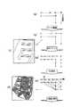
図1は本発明の実施の形態に係る3次元デジタル地図作成方法の概略構成図である。
【0025】
この図1に示す3次元デジタル地図作成方法は、3次元道路モデル化処理部3と、3次元建物モデル化処理部4と、3次元地盤モデル化処理部5とを備えている。
【0026】
(道路モデル化処理部3)
道路モデル化処理3は、まず、地図から道路データを全て読み出し、この道路の道路縁を制約条件として、すなわち道路縁が必ず、生成したTINの辺になるようにTINを発生させる。次に、生成されたTINの中で道路領域内にある可能性が高いと判断される種三角形を探索し、ここを起点にして隣接する三角形の中で道路内にあると判断される三角形を塗りつぶす。
【0027】
そして、塗りつぶしされた三角形に隣接する三角形に対してさらに同じ塗りつぶし処理を繰り返すことで、道路領域を塗りつぶされた三角形群であらわす。この処理は、種三角形が見つからなくなるまで繰り返している。
【0028】
そして、生成できた道路領域において道路中心線を生成して高さ情報を付与する。最後に、高さ情報をもつ中心線から道路領域(道路縁)の各頂点に高さ情報を付与することで、道路の3次元TINモデルを生成している。
【0029】
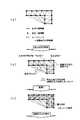
ここで、この説明にあたって、いくつかの概念を図2に基づいて定義する。まず、元の道路縁の端点(End Point)と端点を繋げる線分(点線)を道路のエンドエッジ(End Edge)と呼ぶ。対象三角形において、元の道路縁であった辺を主辺(Key Edge)とし、主辺に対にする頂点を主点(Key Roint)と定義する。また、主点から主辺までの距離を三角形の高さとし、同じ主辺を持つ隣り合う三角形を共主辺三角形と呼ぶことにする。
【0030】
この3次元道路モデル化処理部3は、図1に示すように、前処理6と、TIN発生処理7と、三角形解析処理8と、種三角形探索処理9と、道路領域の塗潰し処理10と、中心線生成処理11と、中心線の3次元化処理12と、道路モデルの生成処理13とを備えている。
【0031】
前処理6は、実際のデジタル地図はポリラインで形成されているが、図3の(a)に示すように、微細な不連続線等も混入しているので、この前処理では、このようなデジタル地図のエラーを修復(ゴミ取り)して図3の(b)に示す道路地図データを得る。図3の(c)は、ゴミ取り後の道路の画面での地図データを示している。
【0032】
次に、後述する種三角形の取捨選択を容易にするために、図3の(b)のエラー修正後の地図データを許容範囲内で全ての道路縁を再構築して、図3の(d)に示すように道路縁におけるポリラインの各セグメントの長さがほぼ同じになるようにする。この前処理6が終わった後にTIN発生処理7を起動させる。
【0033】
次に、TIN発生処理7がこの道路縁を制約条件として図3の(e)に示すようにTINを発生させる。すなわち、道路縁を制約条件として、道路縁が必ず、生成したTIN(Triangulated Irregular network)の辺になるように、TIN(三角形)を発生させている。そして、三角形解析処理8を起動させる。
【0034】
次に、三角形解析処理8は、図4の(a)に示すように、生成された道路領域内に存在する三角形を解析する。この三角形の解析とは、対象三角形に主辺が存在するかどうか、主点の方向を変更するかどうか、三角形の高さが道路縁内に入っているかどうか等の解析を行う。ここで、主点の方向とは、その主点を通る道路縁の方向である。
【0035】
このような解析を全ての三角形に行った後に、種三角形探索処理9を起動させる。
【0036】
種三角形探索処理9は、生成されたTINの中で道路領域内にある可能性が高いと判断される三角形(以下種三角形と称する)を探索する(図4の(b))。
【0037】
この種三角形は、必ず以下の条件を満たしている。
(a)まだ路面として塗潰しされていないこと。
(b)ただひとつの主辺を持つこと。
(c)主点の方向が唯一であり、主辺と平行すること。
(d)三角形の高さが道路幅のしきい値内であること。
(e)共主辺三角形が存在すれば塗りつぶしされていないこと。
(f)主点以外の角が鋭角であること。
(g)共主辺三角形の高さが自分自身より高いこと。
【0038】
これらの条件を満たしているものが種三角形候補として探索されて行き、各種三角形候補に対して共主辺三角形の高さと種三角形候補の高さとの比を該当種三角形候補が道路面に存在する確率とし、すべての種三角形候補に前述確率が最とも高い種三角形候補を種三角形として道路領域の塗潰処理10を起動する。
【0039】
道路領域の塗潰処理10は、道路内に存在すると判定された種三角形を塗潰し、さらに、種三角形に隣接する三角形を前記と同様に塗りつぶして行く。これを道路領域内に三角形が見つからなくなるまで繰り返し行う。
【0040】
つまり、探索した種三角形から図4の(c)に示すように塗りつぶしていく。
【0041】
このとき、三角形▲1▼は種三角形である。三角形▲1▼をカレント三角形として、カレント三角形の主辺とエンドエッジ以外のエッジを共有する別の三角形を探し、塗り潰していく。塗り潰しされた三角形を新たなカレント三角形として、新たに主辺とエンドエッジ以外のエッジを共有する三角形を塗りつぶして行く(番号は塗りつぶしの順番)。
【0042】
次に、道路領域の塗潰処理10は、塗りつぶしされていない三角形を削除して塗り潰しされた三角形だけを残して、図5の(a)に示すような道路領域を生成する。図5の(b)は、不要な三角形を除去した実画面の一例を示している。
【0043】
そして、この処理が終わると中心線生成処理11を起動させる。中心線生成処理11は、図5の(c)に示すように、道路領域を構成する各三角形に対して、ただ一つの主辺を持つ三角形であれば、その主辺と並ぶ三角形に中心線を引く。
【0044】
次に、得られた全ての三角形の中線を繋ぎ、道路中心線を生成する。図5の(d)は道路中心線を引いたときの画面例である。
【0045】
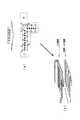
そして、中心線の三次元化処理12を起動させる。中心線の3次元処理12は、道路中心線を構成する各ノードに対して、近傍のLRFデータを探索し、高さの候補値とする。次に滑らかな高さ情報を得るためにスムージング処理を行い、中心線の高さを決定する。
【0046】
例えば、図6の(a)の太い線は道路の中心線、丸印はLRFデータ、点線はサーチエリアである。この図6の(a)において、点線上の任意点から中心線への垂線の長さ(垂線の無いところはもっとも近い頂点までの距離)はサーチ距離であり、言い換えれば、点線上の任意点から中心線までの最短距離は一定であり、サーチ距離である。
【0047】
図6の(b)が点線内のLRF点から中心線まで垂線を引いたことを示すものである。
【0048】
そして、垂足から中心線の始点までの距離を横軸に、LRF点の高さを縦軸にして示したのが図6の(c)である。
【0049】
また、中心線の頂点が複数のLRF点の垂足になることもある。例えば、中心線の始点と終点については、始点は二つのLRF点の垂足になっており、終点は三つのLRF点の終点になっている。
【0050】
そのため、図6の(c)に示すように、始点(Begin)に小さい○が二つ、終点(End)に三つある。
【0051】
図7の(a)は、図6の(c)の各点を最小二乗法を用いて近似直線としたものである。
【0052】
また、図7の(d)は、中心上の元の頂点に対して、中心線に沿って中心線の始点までの距離(横軸)を利用して、近似直線から高さを求めることを示すものである(黒点)。
【0053】
そして、このようにして高さを付与した後に、道路モデルの生成処理13を起動させる。
【0054】
道路モデルの生成処理13は、道路領域を構成する各三角形の各頂点から道路中心線に対して垂線を下ろし、その点の高さを各三角形の頂点、すなわち、道路縁の高さとする。
【0055】
図8の(a)の場合は領域▲1▼内の各三角形が中心線と直接に係わるため、直接に中心線から高さ情報をもらう。
【0056】
領域▲2▼内の三角形の各頂点については、隣のすでに高さ情報が付与された三角形から順次に高さ情報を付与する。例として、図中の点Aと点Bから点Cの高さを計算する。例えば、三角形のA点、B点を結ぶ辺の中心と、BとCとを結ぶ辺の中心を求め、これらの辺の中心を線で結ぶ。このようにして高さ情報を与えて生成したのが図8の(b)の3次元道路画像である。
【0057】
(建物のモデル化処理)
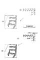
一方、建物のモデル化処理部4は、図1に示すように、前処理15と、屋根の高さの算出処理16と、地面の高さ算出処理17とを備えて、図9に示すように屋根の高さと、地面の高さを求める。
【0058】
これは、建物輪郭はデジタル地図上に記述されているため、建物の上下(屋根と地面)の高さ情報を追加している。
【0059】
前処理15は、デジタル地図は特定の図郭単位に分割されていることが多いため、図10の(a)に示すように、一つの建物が隣接する二つのメッシュに分けられている場合がある。建物のモデル化を行うため、図10の(b)に示すように、分割された建物を連結する必要がある。また、地図に入ったゴミを除外する必要がある。
【0060】
例えば、図10の(a)に示すように、建物Bは図郭Aと図郭Bとに渡っている。このため、図郭Aと図郭Bとの境界線上にある頂点を無くすことで、建物Bの境界線を連結させる。
【0061】
また、例えば建物Cは、頂点数が少なく、かつ形状は細長いので、建物ではないとして除去するゴミ取りを行う。
【0062】
このような処理を各建物について施した後に、屋根の高さ情報の算出処理16を起動させる。
【0063】
屋根の高さ情報の算出処理16は、平面屋根である前提として、建物輪郭内にあるすべてのLRFデータのZ値の最頻値を求めて、平面屋根の高さとする(図10の(c))。
【0064】
このような処理を各建物について施した後に、地面の高さの算出処理17を起動させる。
【0065】
この処理は、図11の(a)に示すように、建物輪郭外にあり、かつ建物輪郭から所定距離(固定値)内にあるLRFデータの最小値を建物の地面の高さとする。
【0066】
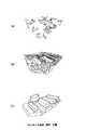
前述の処理によって得られた建物の高さから図11の(b)に示すように、建物の3次元画像が得られる。つまり、図11の(c)に示す2次元原図から図11の(d)に示すような建物の立体図になる。
【0067】
また、地盤のモデル化処理部5は、TIN発生処理20と、建物・道路の内点の削除処理21と、平坦な三角形の探索処理22と、地盤モデルの生成処理23とを備え、LRFデータをベースにして地盤のモデル化を行う。ただし、限られた点数のLRFデータから地盤の推定を行うため、地盤の詳細は無視し、建物や道路の近辺や平坦なオープンスペースに着目して地盤のモデル化を行う。
【0068】
TIN発生工程2は、LRFデータを利用して図12の(a)に示すようにTINを発生させる。
【0069】
次に、建物・道路の内点の削除処理21は、図12の(b)に示すように、建物や道路内に位置するLRFデータを削除した後に、それを頂点とした三角形を除去する。
【0070】
次に、平坦な三角形の探索処理22は、図13の(a)に示すように、平坦なオープンスペースを検出するため、生成された各三角形の法線ベクトルを計算して、しきい値以内の三角形だけを残し、この残した三角形を塗りつぶす(図示せず)。
【0071】
次に、地盤モデルの生成処理23は、図13の(b)に示すように、残された三角形の点の集合に建物の地面輪郭と道路領域の輪郭を制約条件として追加して、TINを新たに発生させ、地盤のTINモデルを生成する(図示せず)。
【0072】
そして、合成化処理部14は、前述の処理によって得られた道路モデル化データ、建物のモデル化データ及び地盤のモデル化データとを入力してこれらを合成し、その結果図13の(c)に示す3次元モデルを得る。
【0073】
【発明の効果】
以上のように本発明によれば、航空機搭載型レーザレンジファインダー(LRF)で取得したLRFデータを利用して、道路、建物、地盤等を素早く3次元化することができるので、3次元地理情報システムの構築に貢献できる。その3次元地理情報システムを利用して、都市計画や防災などの分野に望まれている3次元表示・3次元シミュレーションを効率よく実現することが可能となる。
【図面の簡単な説明】
【図1】本実施の形態の3次元デジタル地図作成装置の概略構成図である。
【図2】道路領域の検出に関する定義を説明する説明図である。
【図3】道路モデルの作成過程を説明する説明図である。
【図4】道路モデルの作成過程を説明する説明図である。
【図5】道路モデルの作成過程を説明する説明図である。
【図6】道路モデルの作成過程を説明する説明図である。
【図7】道路モデルの作成過程を説明する説明図である。
【図8】道路モデルの作成過程を説明する説明図である。
【図9】建物の地盤領域の生成を説明する説明図である。
【図10】建物のモデル化の生成を説明する説明図である。
【図11】建物のモデル化の生成を説明する説明図である。
【図12】地盤のモデル化の生成を説明する説明図である。
【図13】地盤のモデル化の生成を説明する説明図である。
【符号の説明】
3 3次元道路モデル化処理部
4 次元建物モデル化処理部
5 3次元地盤モデル化処理部
14 合成化処理部[0001]
BACKGROUND OF THE INVENTION
The present invention relates to an apparatus for creating a three-dimensional digital map using, for example, altitude data of a feature acquired by an airborne laser range finder (LRF).
[0002]
[Prior art]
Conventional geographic information systems are constructed with two-dimensional digital maps. However, this two-dimensional digital map cannot sufficiently represent the three-dimensional real world because there is no height information.
[0003]
For this reason, there are limits to the use of wireless communication systems that require three-dimensional shape information, disaster prevention simulation, city planning, and the like.
[0004]
For example, when installing a relay point of a wireless communication system in a city, it is impossible to determine whether there is a building that blocks radio waves because the height information of the building is not known, and disaster simulation is performed in the disaster prevention field. However, there are times when it is not known how the disaster will spread, and it took time to make the decision, and there was also the possibility of making a wrong decision.
[0005]
Further, in city planning and landscape design based on two-dimensional map data, there are many cases where the intention of the designer cannot be sufficiently communicated to the client. This is because the visual or spatial image is different between the designer and the client, but in the worst case, the client could be given a completely different image. .
[0006]
These problems are because there is no three-dimensional shape information as described above, but there are three-dimensional maps created by various methods described below.
[0007]
For example, a so-called digital photogrammetry method that obtains 3D data from aerial photographs taken by an operator and creates a 3D map, or stereo matching of aerial photographs automatically by a computer, or even 2D There was a method of creating a three-dimensional digital map by setting a temporary height dimension of several meters per floor on a building in the digital map.
[0008]
In recent years, laser range finder (LRF: Laser Range Finder) that uses eye-safe lasers (laser types that do not cause damage even if they directly enter the eyes) can be used in urban spaces due to the development of laser measurement technology. A method of three-dimensionalizing features such as buildings and trees on the basis of data obtained by installing this LRF on an aircraft, or, for example, comparing a two-dimensional digital map with LRF data, There was also a method to estimate the height of the building from.
[0009]
[Problems to be solved by the invention]
However, the above-mentioned photogrammetry by an operator is effective and accurate for acquiring three-dimensional information of terrain and buildings, but has a drawback that it has a huge amount of work and is inefficient.
[0010]
Digital photogrammetry has been the cause of measurement errors due to the existence of shadows on buildings and parts (occlusions) that are not visible in photographs. Also, the reality is that good results are rarely obtained due to algorithm and photographic digitizer accuracy.
[0011]
The method of creating a 3D digital map by estimating the height of a building is not necessarily the same height per floor for all buildings, so a 3D digital map made in this way The accuracy of was very bad.
[0012]
In addition, since the method of three-dimensionalizing features from LRF data uses only LRF data, in order to model individual buildings, high-density data at intervals of several centimeters to several tens of centimeters must be acquired. There was a problem that the outline of an accurate feature could not be obtained.
[0013]
Furthermore, only the estimation of the building roof has been reported as a method for estimating the building height from the comparison between the two-dimensional digital map and the LRF data. Since the objects (roads, etc.) are line segments and have not yet been made into regions, height information could not be given to these features.
[0014]
The present invention has been made to solve such a problem, and automatically recognizes a region of a two-dimensional digital map and uses the data acquired by an aircraft-mounted LRF to accurately and efficiently perform the past two. An object of the present invention is to provide a three-dimensional device for building, road and ground of a three-dimensional digital map.
[0015]
[Means for Solving the Problems]
The three-dimensional digital map creation device of the present invention reads a two-dimensional digital map of a predetermined region and LRF data obtained by acquiring the region by an aircraft, and defines both data in the same coordinate system;
Means for extracting a road edge line from the two-dimensional digital map defined in the same coordinate system and defining it in the coordinate system;
Means for generating a TIN with the road edge as a constraint;
Among the priorSymbol T IN, it is defined a predetermined condition is satisfied triangle as a seed triangle, and means for searching this,
Means for extracting a road area composed of the filled triangles by erasing the triangles not filled on the TIN after filling adjacent triangles sequentially from the searched seed triangles in the TIN; ,
Means for generating a centerline in the extracted road region;
After generating the center line, LRF data defined in the same coordinate system as that of the two-dimensional digital map is read, and theZ value of the LRF data closest to each node constituting the center line of the road region is calculated. Means to make the height of the node,
And a means for providing a height of the center line to a road edge line forming the road area.
[0016]
The three-dimensional digital map creation device of the present invention is
Road modeling means, building modeling means, ground modeling means and synthesis means,
The road modeling means includes:
Means for reading a two-dimensional digital map of a predetermined area and LRF data obtained by acquiring the area by an aircraft, and defining both data in the same coordinate system;
Means for extracting a road edge line from the two-dimensional digital map defined in the same coordinate system and defining it in the coordinate system;
Means for generating a TIN with the road edge as a constraint;
Amongthe T IN, it is defined a predetermined condition is satisfied triangle as a seed triangle, and means for searching this,
Means for extracting a road area composed of the filled triangles by erasing the triangles not filled on the TIN after filling adjacent triangles sequentially from the searched seed triangles in the TIN; ,
Means for generating a centerline in the extracted road region;
After generating the center line, LRF data defined in the same coordinate system as that of the two-dimensional digital map is read, and the Z value of the LRF data closest to each node constituting the center line of the road region is calculated. Means to make the height of the node,
Means for imparting a height of the center line to a road edge line forming the road region;
Means for generating a three-dimensional model of a road from the centerline given the height and the road edge line given the height;
With
The building modeling means includes:
The LRF data existing in the outline of the building described in the two-dimensional digital map is extracted, the mode value of the Z value is obtained from these LRF data, and the Z value of the mode value is obtained as the building value. Means for the height of the roof,
Means for reading all the LRF data within a predetermined distance from the outline of the building, obtaining a minimum value of the LRF data, and setting the Z value of the minimum value as the height of the ground of the building;
Means for generating a three-dimensional model of the building from the outline of the building, the height of the roof of the building, and the height of the ground of the building;
With
The ground modeling means is:
Using LRF data of the predetermined area, means for generating a triangle onto the predetermined area of the image, after removal of the triangles present beforeSymbol in soil of the road area and buildings, the remaining legal of each triangle Means for obtaining a predetermined open space by calculating a line vector and leaving only triangles within a threshold;
Means for adding the ground contour of the building and the contour of the road region as constraints to the set of remaining triangular LRF data;
Means for generating a new triangle for the addition;
Means for generating a three-dimensional model of the ground based on the height of the vertices of each triangle of the open space;
The synthesizing means includes
The gist of the invention is that it includes means for generating a three-dimensional model obtained by synthesizing a three-dimensional model of a road, a three-dimensional model of a building, and a three-dimensional model of the ground.
[0018]
DETAILED DESCRIPTION OF THE INVENTION
In the present invention, LRF data is added to an existing digital map to create a three-dimensional model of a road, a building, and the ground.
[0019]
First, the existing
[0020]
[Road modeling process]
A road area is generated from a road edge described as a polyline in the past
[0021]
[Building modeling]
In this study, a single flat roof is assumed for simplicity. Since the building outline is described on the 2D map, the mode of the LRF data in the building outline is set to the height of the roof, the LRF data outside the building outline and within a certain distance from the building outline. Let the minimum value be the ground height of the building.
[0022]
[Ground modeling]
Since it is difficult to obtain contour line data in cities where buildings are densely populated, in this study we will model the ground based on LRF data. However, since the ground is designated from the limited number of LRF data, the ground details are ignored, and the ground is modeled by focusing on the vicinity of buildings and roads and flat open spaces.
[0023]
Next, details of the road modeling process 3, the building modeling process 4, and the ground modeling process will be described.
[0024]
FIG. 1 is a schematic configuration diagram of a three-dimensional digital map creation method according to an embodiment of the present invention.
[0025]
The three-dimensional digital map creation method shown in FIG. 1 includes a three-dimensional road modeling processing unit 3, a three-dimensional building modeling processing unit 4, and a three-dimensional ground
[0026]
(Road modeling processor 3)
In the road modeling process 3, first, all road data is read from the map, and a TIN is generated with the road edge of the road as a constraint condition, that is, the road edge is always the side of the generated TIN. Next, a seed triangle that is determined to be highly likely to be in the road area in the generated TIN is searched, and a triangle that is determined to be in the road among the adjacent triangles starting from here is searched. Fill.
[0027]
Then, the road area is represented by a group of filled triangles by repeating the same filling process on the triangles adjacent to the filled triangles. This process is repeated until no seed triangle is found.
[0028]
Then, a road center line is generated in the generated road area, and height information is given. Finally, a three-dimensional TIN model of the road is generated by giving the height information to each vertex of the road area (road edge) from the center line having the height information.
[0029]
Here, in this description, several concepts are defined based on FIG. First, a line segment (end line) connecting the end point (End Point) of the original road edge and the end point is called an end edge (End Edge) of the road. In the target triangle, the side that was the original road edge is defined as the main side (Key Edge), and the vertex that is paired with the main side is defined as the main point (Key Root). The distance from the principal point to the principal side is the height of the triangle, and adjacent triangles having the same principal side are referred to as common principal triangles.
[0030]
As shown in FIG. 1, the three-dimensional road modeling processing unit 3 includes a pre-process 6, a
[0031]
In the preprocessing 6, the actual digital map is formed by polylines, but as shown in FIG. 3A, fine discontinuous lines are also mixed. The error of the digital map is repaired (trash removal) to obtain road map data shown in FIG. FIG. 3C shows map data on the road screen after garbage removal.
[0032]
Next, in order to facilitate the selection of seed triangles to be described later, all road edges are reconstructed within the allowable range of the map data after the error correction of FIG. The length of each segment of the polyline at the road edge is made substantially the same as shown in FIG. After the preprocessing 6 is finished, the
[0033]
Next, the
[0034]
Next, the
[0035]
After performing such an analysis on all the triangles, the seed
[0036]
The seed
[0037]
This kind of triangle always satisfies the following conditions.
(A) It is not yet painted as a road surface.
(B) Having only one main edge.
(C) The direction of the principal point is unique and parallel to the principal side.
(D) The height of the triangle is within the road width threshold.
(E) If a common principal triangle exists, it is not painted.
(F) An angle other than the principal point is an acute angle.
(G) The height of the common edge triangle is higher than itself.
[0038]
Those satisfying these conditions are searched as seed triangle candidates, and the ratio of the height of the common edge triangle to the height of the seed triangle candidate is found on the road surface for each triangle candidate. The road
[0039]
In the road
[0040]
That is, painting is performed from the searched seed triangle as shown in FIG.
[0041]
At this time, triangle (1) is a seed triangle. Using the triangle (1) as the current triangle, another triangle sharing an edge other than the main side and end edge of the current triangle is searched for and filled. The filled triangle is set as a new current triangle, and a triangle that shares an edge other than the main side and the end edge is newly filled (number is the order of filling).
[0042]
Next, the road
[0043]
When this process ends, the center line generation process 11 is activated. As shown in FIG. 5 (c), the center line generation processing 11 is a triangle having only one main side for each triangle constituting the road region. pull.
[0044]
Next, the center line of all the obtained triangles is connected to generate a road center line. FIG. 5D shows a screen example when a road center line is drawn.
[0045]
Then, the three-
[0046]
For example, the thick line in FIG. 6A is the road center line, the circle is the LRF data, and the dotted line is the search area. In FIG. 6A, the length of the perpendicular from the arbitrary point on the dotted line to the center line (the distance from the point where there is no vertical to the nearest vertex) is the search distance, in other words, the arbitrary point on the dotted line. The shortest distance from the center line to the center line is constant and is the search distance.
[0047]
FIG. 6B shows that a perpendicular line is drawn from the LRF point within the dotted line to the center line.
[0048]
FIG. 6C shows the distance from the leg to the start point of the center line on the horizontal axis and the height of the LRF point on the vertical axis.
[0049]
In addition, the vertex of the center line may be a droop of a plurality of LRF points. For example, for the start point and end point of the center line, the start point is a droop of two LRF points, and the end point is the end point of three LRF points.
[0050]
Therefore, as shown in FIG. 6C, there are two small circles at the start point (Begin) and three at the end point (End).
[0051]
FIG. 7A shows an approximate straight line obtained by using the method of least squares for each point shown in FIG. 6C.
[0052]
FIG. 7D shows that the height is obtained from the approximate straight line using the distance (horizontal axis) from the original vertex on the center to the start point of the center line along the center line. It is shown (black dot).
[0053]
Then, after the height is given in this way, the road
[0054]
In the road
[0055]
In the case of FIG. 8A, since each triangle in the area (1) is directly related to the center line, height information is obtained directly from the center line.
[0056]
For each vertex of the triangle in the area {circle around (2)}, height information is assigned sequentially from the adjacent triangle to which height information has already been assigned. As an example, the height of point C is calculated from point A and point B in the figure. For example, the center of the side connecting the points A and B of the triangle and the center of the side connecting B and C are obtained, and the centers of these sides are connected by a line. The three-dimensional road image shown in FIG. 8B is generated by giving height information in this way.
[0057]
(Building modeling process)
On the other hand, as shown in FIG. 1, the building modeling processing unit 4 includes a
[0058]
Since the building outline is described on the digital map, the height information on the top and bottom of the building (roof and ground) is added.
[0059]
In the
[0060]
For example, as shown in (a) of FIG. 10, the building B extends over the figure A and the figure B. For this reason, the boundary line of the building B is connected by eliminating the vertexes on the boundary line between the figure A and the figure B.
[0061]
Further, for example, the building C has a small number of vertices and has an elongated shape.
[0062]
After performing such a process for each building, the calculation process 16 of the roof height information is started.
[0063]
The calculation process 16 of the roof height information is performed on the assumption that the roof is a flat roof, and finds the mode value of the Z values of all the LRF data in the building outline as the height of the flat roof ((c in FIG. 10). )).
[0064]
After performing such processing for each building, the ground height calculation processing 17 is activated.
[0065]
In this process, as shown in FIG. 11A, the minimum value of the LRF data outside the building outline and within a predetermined distance (fixed value) from the building outline is set as the height of the ground of the building.
[0066]
As shown in FIG. 11B, a three-dimensional image of the building is obtained from the height of the building obtained by the above-described processing. In other words, the two-dimensional original drawing shown in FIG. 11C becomes a three-dimensional view of the building as shown in FIG.
[0067]
The ground
[0068]
In the TIN generation step 2, the TIN is generated using the LRF data as shown in FIG.
[0069]
Next, as shown in FIG. 12B, the interior /
[0070]
Next, as shown in FIG. 13A, the flat
[0071]
Next, as shown in FIG. 13B, the ground
[0072]
Then, the
[0073]
【The invention's effect】
As described above, according to the present invention, roads, buildings, grounds, and the like can be quickly three-dimensionalized using LRF data acquired by an aircraft-mounted laser range finder (LRF). Contribute to system construction. By using the 3D geographic information system, it is possible to efficiently realize 3D display and 3D simulation desired in fields such as city planning and disaster prevention.
[Brief description of the drawings]
FIG. 1 is a schematic configuration diagram of a three-dimensional digital map creating apparatus according to an embodiment.
FIG. 2 is an explanatory diagram for explaining a definition related to detection of a road region.
FIG. 3 is an explanatory diagram for explaining a road model creation process;
FIG. 4 is an explanatory diagram for explaining a road model creation process;
FIG. 5 is an explanatory diagram for explaining a road model creation process;
FIG. 6 is an explanatory diagram for explaining a road model creation process;
FIG. 7 is an explanatory diagram for explaining a road model creation process;
FIG. 8 is an explanatory diagram for explaining a road model creation process;
FIG. 9 is an explanatory diagram illustrating generation of a ground area of a building.
FIG. 10 is an explanatory diagram illustrating generation of building modeling.
FIG. 11 is an explanatory diagram illustrating generation of building modeling.
FIG. 12 is an explanatory diagram illustrating generation of ground modeling.
FIG. 13 is an explanatory diagram illustrating generation of ground modeling.
[Explanation of symbols]
3 3D road modeling processing unit 4D building
Claims (9)
Translated fromJapanese前記同一座標系に定義された前記二次元デジタル地図から道路縁線を抜き出し、これを前記座標系で定める手段と、
前記道路縁線を制約条件とするTINを発生させる手段と、
前記TINの中で、所定の条件を満たす三角形を種三角形として定義させ、これを探索する手段と、
前記TINにおいて、探索された種三角形から順次に隣接する三角形を塗り潰した後に、前記TIN上で塗り潰しされていない三角形を消去することによって前記塗り潰しされた三角形で構成される道路領域を抽出する手段と、
前記抽出された道路領域において、中心線を生成する手段と、
前記中心線を生成した後に、前記二次元デジタル地図と同一座標系に定義されたLRFデータを読み込み、前記道路領域の中心線を構成する各ノードに最も近いLRFデータのZ値を前記中心線のノードの高さとする手段と、
前記中心線の高さを前記道路領域を形成する道路縁線に付与する手段と
を有することを特徴とする3次元デジタル地図作成装置。Means for reading a two-dimensional digital map of a predetermined area and LRF data obtained by acquiring the area by an aircraft, and defining both data in the same coordinate system;
Means for extracting a road edge line from the two-dimensional digital map defined in the same coordinate system and defining it in the coordinate system;
Means for generating a TIN with the road edge as a constraint;
Among the priorSymbol T IN, it is defined a predetermined condition is satisfied triangle as a seed triangle, and means for searching this,
Means for extracting a road region composed of the filled triangles by erasing the triangles not filled on the TIN after filling adjacent triangles sequentially from the searched seed triangles in the TIN; ,
Means for generating a centerline in the extracted road region;
After generating the center line, LRF data defined in the same coordinate system as that of the two-dimensional digital map is read, and the Z value of the LRF data closest to each node constituting the center line of the road region is calculated. Means to make the height of the node,
Means for providing a height of the center line to a road edge line forming the road area.
を有することを特徴とする請求項1記載の3次元デジタル地図作成装置。2. The three-dimensional digital map creation device according to claim 1, further comprising means for generating a three-dimensional model of a road from the center line to which the height is given and the road edge line to which the height is given.
前記道路領域を構成する各三角形の道路縁ではない二辺の各中心を求め、これらの辺の中心を結ぶことで得ることを特徴とする請求項1又は2記載の3次元デジタル地図作成装置。The centerline is
3. The three-dimensional digital map creation device according to claim 1, wherein the three-dimensional digital map creation device is obtained by obtaining each center of two sides that are not road edges of each triangle constituting the road region and connecting the centers of these sides.
前記道路領域を構成する各三角形の頂点から前記中心線に垂線を下ろしたときの交点のZ値をその縁の点の高さとして付与する
ことを特徴とする請求項1、2又は3のいずれかに記載の3次元デジタル地図作成装置。The height of the road edge line is given as follows:
The Z value of the intersection point when a perpendicular is dropped from the vertex of each triangle constituting the road area to the center line is given as the height of the edge point. A three-dimensional digital map creation device according to the above.
前記建物の輪郭線から所定距離以内にある全てのLRFデータを読み、これらのLRFデータの最小値を求め、この最小値のZ値を前記所定距離内の建物の地盤の高さとする手段と
を有することを特徴とする請求項1記載の3次元デジタル地図作成装置。The LRF data existing in the outline of the building described in the two-dimensional digital map is extracted, the mode value of the Z value is obtained from these LRF data, and the Z value of the mode value is obtained as the building value. Means for the height of the roof,
Means for reading all the LRF data within a predetermined distance from the outline of the building, obtaining a minimum value of these LRF data, and setting the Z value of the minimum value as the height of the ground of the building within the predetermined distance; The three-dimensional digital map creating apparatus according to claim 1, comprising:
を有することを特徴とする請求項5記載の3次元デジタル地図作成装置。6. The three-dimensional digital map creating apparatus according to claim 5, further comprising means for generating a three-dimensional model of the building from the outline of the building, the height of the roof of the building, and the height of the ground of the building.
前記道路領域と建物の地盤内に存在する三角形を除去した後に、残った各三角形の法線ベクトルを計算し、閾値以内の三角形だけを残すことで所定のオープンスペースを得る手段と、
残された三角形のLRFデータの集合に、建物の前記地盤の輪郭と前記道路領域の輪郭とを制約条件として追加する手段と、
該追加後に新たな三角形を発生する手段と
を有することを特徴とする請求項1記載の3次元デジタル地図作成装置。Means for generating a triangle in the image of the predetermined area using the LRF data of the predetermined area;
After removal of the triangles present in theground plateof the road area and buildings, the remaining vector of each triangle is calculated, means for obtaining a predetermined open space by leaving only triangle within a threshold value,
Means for adding the ground contour of the building and the contour of the road region as constraints to the set of remaining triangular LRF data;
2. A three-dimensional digital map creating apparatus according to claim 1, further comprising means for generating a new triangle after the addition.
を有することを特徴とする請求項7記載の3次元デジタル地図作成装置。8. The three-dimensional digital map creation device according to claim 7, further comprising means for generating a three-dimensional model of the ground based on the height of the vertex of each triangle in the open space.
道路のモデル化手段、建物のモデル化手段、地盤のモデル化手段並びに合成化手段を有し、
前記道路のモデル化手段は、
所定の地域の二次元デジタル地図と、航空機によって前記地域を取得したLRFデータとを読み出し、両方のデータを同一座標系に定義する手段と、
前記同一座標系に定義された前記二次元デジタル地図から道路縁線を抜き出し、これを前記座標系で定める手段と、
前記道路縁線を制約条件とするTINを発生させる手段と、
前記TINの中で、所定の条件を満たす三角形を種三角形として定義させ、これを探索する手段と、
前記TINにおいて、探索された種三角形から順次に隣接する三角形を塗り潰した後に、前記TIN上で塗り潰しされていない三角形を消去することによって前記塗り潰しされた三角形で構成される道路領域を抽出する手段と、
前記抽出された道路領域において、中心線を生成する手段と、
前記中心線を生成した後に、前記二次元デジタル地図と同一座標系に定義されたLRFデータを読み込み、前記道路領域の中心線を構成する各ノードに最も近いLRFデータのZ値を前記中心線のノードの高さとする手段と、
前記中心線の高さを前記道路領域を形成する道路縁線に付与する手段と、
前記高さが付与された中心線及び前記高さが付与された道路縁線から道路の3次元モデルを生成する手段と、
を備え、
前記建物のモデル化手段は、
前記二次元デジタル地図に記述されている建物の輪郭線内に存在する前記LRFデータを抽出し、これらのLRFデータからのZ値の最頻値を求め、この最頻値のZ値を前記建物の屋根の高さとする手段と、
前記建物の輪郭線から所定距離以内にある全てのLRFデータを読み、これらのLRFデータの最小値を求め、この最小値のZ値を前記建物の地盤の高さとする手段と、
前記建物の輪郭線と建物の屋根の高さと前記建物の地盤の高さとから前記建物の3次元モデルを生成する手段と、
を備え、
前記地盤のモデル化手段は、
前記所定の地域のLRFデータを用いて、該所定の地域の画像に三角形を生成する手段と、
前記道路領域と建物の前記地盤内に存在する三角形を除去した後に、残った各三角形の法線ベクトルを計算し、閾値以内の三角形だけを残すことで所定のオープンスペースを得る手段と、
残された三角形のLRFデータの集合に、建物の地盤の輪郭と前記道路領域の輪郭とを制約条件として追加する手段と、
該追加に新たな三角形を発生する手段と、
前記オープンスペースの各三角形の頂点の高さに基づいて地盤の3次元モデルを生成する手段と
を備え、
前記合成化手段は、
道路の3次元モデルと建物の3次元モデルと地盤の3次元モデルとを合成した3次元モデルを生成する手段と
を有することを特徴とする3次元デジタル地図作成装置。3D digital map creation device
Road modeling means, building modeling means, ground modeling means and synthesis means,
The road modeling means includes:
Means for reading a two-dimensional digital map of a predetermined area and LRF data obtained by acquiring the area by an aircraft, and defining both data in the same coordinate system;
Means for extracting a road edge line from the two-dimensional digital map defined in the same coordinate system and defining it in the coordinate system;
Means for generating a TIN with the road edge as a constraint;
Among the priorSymbol T IN, it is defined a predetermined condition is satisfied triangle as a seed triangle, and means for searching this,
Means for extracting a road area composed of the filled triangles by erasing the triangles not filled on the TIN after filling adjacent triangles sequentially from the searched seed triangles in the TIN; ,
Means for generating a centerline in the extracted road region;
After generating the center line, LRF data defined in the same coordinate system as that of the two-dimensional digital map is read, and the Z value of the LRF data closest to each node constituting the center line of the road region is calculated. Means to make the height of the node,
Means for imparting a height of the center line to a road edge line forming the road region;
Means for generating a three-dimensional model of a road from the centerline given the height and the road edge line given the height;
With
The building modeling means includes:
The LRF data existing in the outline of the building described in the two-dimensional digital map is extracted, the mode value of the Z value is obtained from these LRF data, and the Z value of the mode value is obtained as the building value. Means for the height of the roof,
Means for reading all the LRF data within a predetermined distance from the outline of the building, obtaining a minimum value of the LRF data, and setting the Z value of the minimum value as the height of the ground of the building;
Means for generating a three-dimensional model of the building from the outline of the building, the height of the roof of the building, and the height of the ground of the building;
With
The ground modeling means is:
Means for generating a triangle in the image of the predetermined area using the LRF data of the predetermined area;
After removal of the triangles present beforeSymbol insoil of the road area and buildings, the remaining vector of each triangle is calculated, means for obtaining a predetermined open space by leaving only triangle within a threshold value,
Means for adding the ground contour of the building and the contour of the road region as constraints to the set of remaining triangular LRF data;
Means for generating a new triangle for the addition;
Means for generating a three-dimensional model of the ground based on the height of the vertices of each triangle of the open space;
The synthesizing means includes
A three-dimensional digital map creation device comprising means for generating a three-dimensional model obtained by synthesizing a three-dimensional model of a road, a three-dimensional model of a building, and a three-dimensional model of the ground.
Priority Applications (1)
| Application Number | Priority Date | Filing Date | Title |
|---|---|---|---|
| JP2000283281AJP4619504B2 (en) | 2000-09-19 | 2000-09-19 | 3D digital map generator |
Applications Claiming Priority (1)
| Application Number | Priority Date | Filing Date | Title |
|---|---|---|---|
| JP2000283281AJP4619504B2 (en) | 2000-09-19 | 2000-09-19 | 3D digital map generator |
Publications (2)
| Publication Number | Publication Date |
|---|---|
| JP2002092658A JP2002092658A (en) | 2002-03-29 |
| JP4619504B2true JP4619504B2 (en) | 2011-01-26 |
Family
ID=18767667
Family Applications (1)
| Application Number | Title | Priority Date | Filing Date |
|---|---|---|---|
| JP2000283281AExpired - Fee RelatedJP4619504B2 (en) | 2000-09-19 | 2000-09-19 | 3D digital map generator |
Country Status (1)
| Country | Link |
|---|---|
| JP (1) | JP4619504B2 (en) |
Families Citing this family (17)
| Publication number | Priority date | Publication date | Assignee | Title |
|---|---|---|---|---|
| JP4226360B2 (en)* | 2003-03-10 | 2009-02-18 | 株式会社パスコ | Laser data filtering method and program |
| JP2007225628A (en)* | 2004-03-31 | 2007-09-06 | Pioneer Electronic Corp | Map creation device |
| JP4726179B2 (en)* | 2004-06-23 | 2011-07-20 | 株式会社ジオ技術研究所 | Method for generating three-dimensional display data of directional polygon |
| JP4543820B2 (en)* | 2004-08-19 | 2010-09-15 | 朝日航洋株式会社 | Three-dimensional data processing apparatus and program |
| JP2009020779A (en)* | 2007-07-13 | 2009-01-29 | Kokusai Kogyo Co Ltd | Information processing system of building, and information processing method of building |
| JP5088627B2 (en)* | 2008-04-30 | 2012-12-05 | 国際航業株式会社 | Multi-matching method |
| JP4727696B2 (en)* | 2008-06-24 | 2011-07-20 | 株式会社ジオ技術研究所 | Method for generating 3D electronic map data |
| EP2518444B1 (en)* | 2011-04-29 | 2014-06-11 | Harman Becker Automotive Systems GmbH | Navigation device and method of determining a height coordinate |
| JP6543475B2 (en)* | 2015-01-29 | 2019-07-10 | 田中 成典 | Surveying result generator |
| CN111238505B (en)* | 2018-11-29 | 2023-11-24 | 沈阳美行科技股份有限公司 | Road line segment drawing method, device and related system of road map |
| CN112700531B (en)* | 2020-12-18 | 2023-05-16 | 武汉大学 | Hierarchical household display method for building inclination model fused with vector house type diagram |
| JP7742294B2 (en)* | 2021-12-17 | 2025-09-19 | 国際航業株式会社 | Road edge heightening device |
| CN114446118B (en)* | 2022-01-27 | 2023-05-23 | 中国人民解放军战略支援部队信息工程大学 | Semi-physical total station teaching system |
| CN114446108B (en)* | 2022-01-27 | 2023-05-23 | 中国人民解放军战略支援部队信息工程大学 | Semi-physical simulation training method for total station |
| JPWO2024019032A1 (en)* | 2022-07-19 | 2024-01-25 | ||
| CN116186864B (en)* | 2023-04-24 | 2023-07-07 | 中南冶勘资源环境工程有限公司 | Deep foundation pit model rapid modeling method and system based on BIM technology |
| CN116702273B (en)* | 2023-05-22 | 2025-04-08 | 中南建筑设计院股份有限公司 | Grasshopper and Revit road BIM model generation method and system |
Family Cites Families (1)
| Publication number | Priority date | Publication date | Assignee | Title |
|---|---|---|---|---|
| JP3496418B2 (en)* | 1996-12-24 | 2004-02-09 | 住友電気工業株式会社 | Three-dimensional CG map display device and in-vehicle navigation device |
- 2000
- 2000-09-19JPJP2000283281Apatent/JP4619504B2/ennot_activeExpired - Fee Related
Also Published As
| Publication number | Publication date |
|---|---|
| JP2002092658A (en) | 2002-03-29 |
Similar Documents
| Publication | Publication Date | Title |
|---|---|---|
| Yan et al. | Integration of 3D objects and terrain for 3D modelling supporting the digital twin | |
| JP4619504B2 (en) | 3D digital map generator | |
| Zhou et al. | Urban 3D GIS from LiDAR and digital aerial images | |
| Truong-Hong et al. | Octree-based, automatic building facade generation from LiDAR data | |
| US20090105954A1 (en) | Geospatial modeling system and related method using multiple sources of geographic information | |
| WO2018061010A1 (en) | Point cloud transforming in large-scale urban modelling | |
| Karan et al. | Digital modeling of construction site terrain using remotely sensed data and geographic information systems analyses | |
| Laycock et al. | Automatically generating large urban environments based on the footprint data of buildings | |
| US20230419501A1 (en) | Image analysis for aerial images | |
| KR100657870B1 (en) | Ground Level Extraction Method Using Aerial Laser Survey Data | |
| RU2638638C1 (en) | Method and system of automatic constructing three-dimensional models of cities | |
| Komadina et al. | Automated 3D urban landscapes visualization using open data sources on the example of the city of Zagreb | |
| CN115979125A (en) | Method, system, device and storage medium for BIM combined with UAV to measure earthwork | |
| CN115761279A (en) | Spatial layout similarity detection method, device, storage medium and device | |
| US20250258968A1 (en) | Automated monitoring of constructional sites | |
| Pepe et al. | An effective Method For 3D Modelling of Urban Areas from Aerial Images and LiDAR data | |
| Ramadhani | An Analysis of the Three-Dimensional Modelling Using LiDAR Data and Unmanned Aerial Vehicle (UAV)(Case Study: Institut Teknologi Sepuluh Nopember, Sukolilo Campus) | |
| Zhang et al. | Multi-view 3D city model generation with image sequences | |
| Jebur | Application of 3D City Model and Method of Create of 3D Model-A Review Paper | |
| JP7663340B2 (en) | Small Area Generator | |
| Maciąg et al. | Implementation of unmanned aerial vehicles in the automated assessment of geodetic database validity | |
| US11163920B2 (en) | Method for modeling structure in variable terrain | |
| Gorte et al. | Representation and reconconstruction of triangular irregular networks with vertical walls | |
| F Laefer et al. | New advances in automated urban modelling from airborne laser scanning data | |
| Gülch et al. | Semi-automatic object extraction–lessons learned |
Legal Events
| Date | Code | Title | Description |
|---|---|---|---|
| A621 | Written request for application examination | Free format text:JAPANESE INTERMEDIATE CODE: A621 Effective date:20070816 | |
| A977 | Report on retrieval | Free format text:JAPANESE INTERMEDIATE CODE: A971007 Effective date:20091027 | |
| A131 | Notification of reasons for refusal | Free format text:JAPANESE INTERMEDIATE CODE: A131 Effective date:20091104 | |
| A521 | Request for written amendment filed | Free format text:JAPANESE INTERMEDIATE CODE: A523 Effective date:20091228 | |
| A131 | Notification of reasons for refusal | Free format text:JAPANESE INTERMEDIATE CODE: A131 Effective date:20100126 | |
| A521 | Request for written amendment filed | Free format text:JAPANESE INTERMEDIATE CODE: A523 Effective date:20100226 | |
| A131 | Notification of reasons for refusal | Free format text:JAPANESE INTERMEDIATE CODE: A131 Effective date:20100427 | |
| A521 | Request for written amendment filed | Free format text:JAPANESE INTERMEDIATE CODE: A523 Effective date:20100607 | |
| A131 | Notification of reasons for refusal | Free format text:JAPANESE INTERMEDIATE CODE: A131 Effective date:20100720 | |
| A521 | Request for written amendment filed | Free format text:JAPANESE INTERMEDIATE CODE: A523 Effective date:20100806 | |
| TRDD | Decision of grant or rejection written | ||
| A01 | Written decision to grant a patent or to grant a registration (utility model) | Free format text:JAPANESE INTERMEDIATE CODE: A01 Effective date:20101019 | |
| A01 | Written decision to grant a patent or to grant a registration (utility model) | Free format text:JAPANESE INTERMEDIATE CODE: A01 | |
| A61 | First payment of annual fees (during grant procedure) | Free format text:JAPANESE INTERMEDIATE CODE: A61 Effective date:20101027 | |
| FPAY | Renewal fee payment (event date is renewal date of database) | Free format text:PAYMENT UNTIL: 20131105 Year of fee payment:3 | |
| R150 | Certificate of patent or registration of utility model | Free format text:JAPANESE INTERMEDIATE CODE: R150 | |
| LAPS | Cancellation because of no payment of annual fees |