JP4615468B2 - Imaging device - Google Patents
Imaging deviceDownload PDFInfo
- Publication number
- JP4615468B2 JP4615468B2JP2006081569AJP2006081569AJP4615468B2JP 4615468 B2JP4615468 B2JP 4615468B2JP 2006081569 AJP2006081569 AJP 2006081569AJP 2006081569 AJP2006081569 AJP 2006081569AJP 4615468 B2JP4615468 B2JP 4615468B2
- Authority
- JP
- Japan
- Prior art keywords
- unit
- data
- information
- image data
- lens
- Prior art date
- Legal status (The legal status is an assumption and is not a legal conclusion. Google has not performed a legal analysis and makes no representation as to the accuracy of the status listed.)
- Expired - Fee Related
Links
Images


Landscapes
- Studio Devices (AREA)
Description
Translated fromJapanese本発明は、撮影レンズとイメージセンサを内蔵するレンズユニットと、このレンズユニットが着脱自在とされた本体ユニットとで構成される撮影装置に関するものである。 The present invention relates to a photographing apparatus including a photographing lens and a lens unit including an image sensor, and a main body unit in which the lens unit is detachable.
近年では、CCDイメージセンサ等のイメージセンサによって、被写体を撮影し、その画像データをメモリカード等に記憶するデジタルカメラが普及している。画像データをメモリカード等に記憶する場合に、通常では画像データを非可逆圧縮して記録しているが、可逆圧縮(ロスレス圧縮)を採用したデジタルカメラも知られている(例えば特許文献1を参照)。 In recent years, digital cameras that photograph a subject with an image sensor such as a CCD image sensor and store the image data in a memory card or the like have become widespread. When image data is stored in a memory card or the like, the image data is usually recorded with lossy compression, but a digital camera employing lossless compression (lossless compression) is also known (for example, see Patent Document 1). reference).
非可逆圧縮は、圧縮効率が高いが、多少の情報損失がある。このため商用目的など高画質が要求される場合には、圧縮前のデータを完全に復元できる可逆圧縮が用いられることが多い。また、撮影後に種々の画像処理を施したりする場合には、デジタルカメラで画像処理を行っていないRAWデータ形式の画像データを可逆圧縮した画像データを記録することが多い。 Lossy compression has high compression efficiency, but has some information loss. For this reason, when high image quality is required for commercial purposes, lossless compression that can completely restore data before compression is often used. When various image processing is performed after shooting, image data obtained by reversibly compressing image data in a RAW data format that has not been subjected to image processing by a digital camera is often recorded.
一方、例えば特許文献2に示されるように、撮影レンズとイメージセンサ(撮像素子)とを筐体に組み込んだレンズユニット(プラグインユニット)と、このレンズユニットが取り付けられ、そのレンズユニットのイメージセンサで撮影して得られる画像データを受け取るようにした本体ユニット(カメラ本体)とからなる撮影装置が知られている。 On the other hand, as shown in Patent Document 2, for example, a lens unit (plug-in unit) in which a photographing lens and an image sensor (imaging device) are incorporated in a housing, and the lens unit are attached, and the image sensor of the lens unit. 2. Description of the Related Art There is known a photographing apparatus including a main unit (camera main body) that receives image data obtained by photographing with a camera.
上記撮影装置では、レンズユニットとしては、ズームレンズや広角レンズ等の各種のものが用意されており、種々のレンズユニットを交換して利用できるようにされている。また、本体ユニットには、マイクロコンピュータが内蔵されており、装着されたレンズユニットの動作を制御するようにされている。
ところで、上記のようなレンズユニットと本体ユニットとからなる撮影装置においては、撮影で得られる画像データをレンズユニットから本体ユニットに転送する必要がある。RAWデータを記録しようとする場合に、そのRAWデータは、非可逆圧縮の際に最終的に用いられる輝度及び各色差の画像データ(YCデータ)に比べて非常にデータ量が多い。例えばYCデータが各8ビットであるのに対し、RAWデータは各10〜16ビット程度であり、バイト(8ビット)単位で転送処理を行うとすれば、実質的に2倍の転送量であって2倍の転送時間が必要となる。しかしながら、このように転送時間が長くなると、レンズユニットは、その閉ざされた筐体の狭い空間内にイメージセンサや、これを駆動するための回路素子、各種信号処理,データ転送ようの通信回路等の回路素子などが配置してあるため、それらの発熱による温度上昇が問題になる。レンズユニットの内部が温度上昇した場合には、画像信号のS/N比の低下、動作不良等が発生しやすくなる。 By the way, in the photographing apparatus including the lens unit and the main body unit as described above, it is necessary to transfer image data obtained by photographing from the lens unit to the main body unit. When RAW data is to be recorded, the amount of data of the RAW data is much larger than the luminance and color difference image data (YC data) finally used in the lossy compression. For example, YC data is 8 bits each, while RAW data is about 10 to 16 bits each. If transfer processing is performed in units of bytes (8 bits), the transfer amount is substantially doubled. Twice the transfer time is required. However, when the transfer time becomes long in this way, the lens unit is connected to the image sensor, a circuit element for driving the image sensor, various signal processing, a communication circuit for data transfer, etc. in the narrow space of the closed casing. Therefore, a rise in temperature due to the heat generation becomes a problem. When the temperature inside the lens unit rises, a decrease in the S / N ratio of the image signal, malfunction, etc. are likely to occur.
本発明は上記問題を解消するためになされたもので、RAWデータの転送時においても、レンズユニットの内部が温度上昇を抑え、画像信号のS/N比の低下、動作不良等の発生を防止することができる撮影装置を提供することを目的とする。 The present invention has been made to solve the above-described problems. Even when RAW data is transferred, the temperature inside the lens unit is suppressed to prevent a decrease in the S / N ratio of the image signal and the occurrence of malfunction. An object of the present invention is to provide a photographing apparatus capable of performing the above.
上記目的を達成するために、請求項1記載の撮影装置では、本体ユニットまたはレンズユニットの一方に、RAWデータ形式の画像データを記録媒体に記録する第1記録モードと輝度及び各色差の画像データを記録媒体に記録する第2記録モードとを選択する選択手段及びこの選択手段によって選択された記録モードを各ユニットに設定するモード設定手段を有し、レンズユニットは、イメージセンサから出力されるアナログ信号をデジタル変換することでRAWデータ形式の画像データを生成するデジタル変換手段と、画像データを可逆圧縮する可逆圧縮手段と、RAWデータ形式の画像データを輝度及び各色差の画像データに変換するYC変換手段と、画像データを本体ユニットに送信するデータ送信手段と、第1記録モードが設定されているときに、デジタル変換手段からのRAWデータ形式の画像データを可逆圧縮手段を介してデータ送信手段に送り、第2記録モードが設定されているときに、デジタル変換手段からのRAWデータ形式の画像データをYC変換手段を介してデータ送信手段に送るデータ経路制御手段とを有し、本体ユニットは、データ送信手段からの画像データを受信する受信手段と、第2記録モードが設定されているときに、輝度及び各色差の画像データを非可逆圧縮する非可逆圧縮手段と、第1記録モードが設定されているときに、データ受信手段によって受信した可逆圧縮されたRAWデータ形式の画像データを記録媒体に記録し、第2記録モードが設定されているときに、データ受信手段によって受信され、非可逆圧縮手段によって非可逆圧縮された輝度及び各色差の画像データを記録媒体に記録する記録制御手段とを有するように構成したものである。In order to achieve the above object, in the photographing apparatus according to claim 1,the first recording mode for recording the image data in the RAW data format on the recording medium, the image data of the luminance and each color difference, in either themain unit or the lens unit. A second recording mode for recording the image on the recording medium, and a mode setting unit for setting the recording mode selected by the selection unit in each unit. The lens unit is an analog output from the image sensor. Digital conversion means for generating image data in the RAW data format by digitally converting the signal, reversible compression means for reversibly compressing the image data, and YC for converting the image data in the RAW data format into image data of luminance and each color difference The conversion means, the data transmission means for transmitting the image data to the main unit, and the first recording mode are set. RAW data format image data from the digital conversion means is sent to the data transmission means via the lossless compression means, and when the second recording mode is set, the RAW data format image from the digital conversion means is set. A data path control unit that sends data to the data transmission unit via the YC conversion unit, and the main unit receives a reception unit that receives image data from the data transmission unit, and the second recording mode is set In addition, irreversible compression means for irreversibly compressing image data of luminance and each color difference, and reversibly compressed RAW data format image data received by the data reception means when the first recording mode is set are recorded. When data is recorded on a medium and the second recording mode is set, it is received by the data receiving means and is irreversibly compressed by the irreversible compression means. Were those configured to have aluminance and a recording control means for recording theimage data for each color difference.
請求項2記載の撮影装置では、データ経路制御手段を、第2記録モードが設定されているときに、デジタル変換手段からのRAWデータ形式の画像データをYC変換手段及び可逆圧縮手段を介してデータ送信手段に送るようにし、本体ユニットに、レンズユニットで可逆圧縮された輝度及び各色差の画像データを伸張する可逆伸張手段を設け、非可逆圧縮手段が、可逆伸張手段で伸張された輝度及び各色差の画像データを非可逆圧縮するようにしたものである。According to a second aspect of the present invention,when the second recording mode is set , thedata path control means converts the RAW data format image data from the digital conversion means to the data via the YC conversion means and the lossless compression means. The main body unit is provided with reversible decompression means for decompressing the reversibly compressed luminance and color difference image data in the main unit, and the irreversible compression means is provided with the reversible decompression means for the luminance Color difference image data is irreversibly compressed .
請求項3記載の撮影装置では、レンズユニットに、撮影に関する撮影情報を生成する情報生成手段と、撮影情報を可逆圧縮されたRAWデータ形式の画像データに付加する付加手段とを設け、記録制御手段を、撮影情報が付加された画像データを記録媒体に記録するようにしたものである。また、請求項4記載の撮影装置では、レンズユニットに、撮影に関する撮影情報を生成する情報生成手段と、この撮影情報を本体ユニットに送信する情報送信手段とを設け、本体ユニットに、情報送信手段からの撮影情報を受信する情報受信手段と、撮影情報を画像データに付加する付加手段とを設け、記録制御手段が、撮影情報が付加された画像データを記録媒体に記録するようにしたものである。さらに、請求項5記載の撮影装置では、付加手段が、圧縮された画像データに撮影情報を付加するようにしたものである。そして、請求項6記載の撮影装置では、付加手段が、レンズユニットからの撮影情報とともに本体ユニット固有の情報を付加するようにしたものである。According to athird aspect of the present invention, thelens unit is providedwith information generating means for generating shooting information relating to shooting, and an adding means for adding the shooting information to image data in a losslessly compressed RAW data format, and a recording control means. The image data to which the shooting information is added is recorded on a recording medium. According to a fourth aspect of the present invention, the lens unit is provided with information generating means for generating shooting information relating to shooting, and information transmitting means for transmitting the shooting information to the main unit, and the main unit is provided with information transmitting means. Provided with an information receiving means for receiving the shooting information from the camera and an adding means for adding the shooting information to the image data, and the recording control means for recording the image data with the shooting information added to the recording medium. is there. Further, in the photographing apparatus according to the fifth aspect, the adding means adds photographing information to the compressed image data. In the photographing apparatus according to the sixth aspect, the adding means adds information unique to the main unit together with photographing information from the lens unit .
請求項7記載の撮影装置では、情報送信手段及び情報受信手段の転送速度は、データ送信手段及びデータ受信手段の転送速度よりも低速としたものである。また、請求項8記載の撮影装置では、情報送信手段及び情報受信手段として、レンズユニットと本体ユニットとの間の制御信号を送受信する手段を用いたものである。さらに、請求項9記載の撮影装置では、情報送信手段及び情報受信手段の転送、及びデータ送信手段及びデータ受信手段の転送を、シリアル通信によって行うようにしたものである。In the photographing apparatus according to theseventh aspect,the transfer rates of the information transmitting unit and the information receiving unit are set lower than the transfer rates of the data transmitting unit and the data receiving unit. In the photographing apparatus according to the eighth aspect, as the information transmitting means and the information receiving means, means for transmitting and receiving a control signal between the lens unit and the main unit is used. Further, in the photographing apparatus according to the ninth aspect, the transfer of the information transmission unit and the information reception unit and the transfer of the data transmission unit and the data reception unit are performed by serial communication .
本発明の撮影装置によれば、レンズユニットに設けた可逆圧縮手段によって可逆圧縮されたRAWデータ形式の画像データを本体ユニットに送信して、これを記録媒体に記録するようにしたから、本体ユニットに送るべきデータ量が少なくなり、短時間で転送が可能となるとともに、可逆圧縮手段の回路規模が小さく発熱を少なくできるので、レンズユニット内部の温度上昇を抑えることができる。 According to the photographing apparatus of the present invention, the image data in the RAW data format that is reversibly compressed by the reversible compression means provided in the lens unit is transmitted to the main unit and is recorded on the recording medium. The amount of data to be sent to the camera can be reduced, transfer can be performed in a short time, and the circuit scale of the reversible compression means is small, so that heat generation can be reduced.
本発明を実施した撮影装置としてのデジタルカメラを図1に示す。このデジタルカメラ10は、本体ユニット11とレンズユニット12とから構成される。レンズユニット12は、筐体12aに内蔵された撮影レンズ13とこの撮影レンズ13によって結像する被写体像を光電変換するイメージセンサ14とを有している。イメージセンサ14としては、CCDイメージセンサを用いているが、MOS型等であってもよい。 A digital camera as a photographing apparatus embodying the present invention is shown in FIG. The digital camera 10 includes a
本体ユニット11は、装着されたレンズユニット12との間で種々の信号を授受することにより、イメージセンサ14等を駆動し、イメージセンサ14で被写体を撮影して得られる画像データを取得する。本体ユニット11に対して、レンズユニット12は着脱自在としてあり、レンズユニット12としては、例えば撮影レンズ13の焦点距離が異なるもの、イメージセンサ14の画素数が異なるもの、赤外線撮影が可能なものなど、複数種類のものが用意されている。これにより、撮影意図・撮影シーンに応じたレンズユニット12を任意に選択して本体ユニット11に装着して撮影を行うことができる。 The
レンズユニット12の背面に、バヨネット爪15を形成したマウント部16を設けてある。一方、本体ユニット11の前面には、バヨネット溝17を形成したマウント部18を設けてある。レンズユニット12は、そのバヨネット爪16をバヨネット溝17に位置合わせして押し込み、時計方向に回転して固定位置とすることによって本体ユニット11に装着される。なお、このように固定位置とされたときに、イメージセンサ14の受光面が横長の姿勢となるようにしてある。 On the back surface of the
マウント部18には、ロックピン20を設けてある。ロックピン20は、前方に突出したロック位置と、本体ユニット11内に移動した解除位置との間で移動自在としてあり、ロック位置に向けて付勢してある。上記のようにレンズユニット12を本体ユニット11に装着する際に、ロックピン20は、マウント部16に押圧されることでバネの付勢に抗して解除位置に移動し、レンズユニット12が固定位置まで回転されると、マウント部16に形成されたピン穴(図示省略)と係合してレンズユニット12の回転をロックする。これにより、レンズユニット12が不用意に回転して本体ユニット11から脱落することを防止する。 A
マウント部18の近傍には、ロック解除ボタン21を設けてあり、このロック解除ボタン21を押圧操作すると、ロックピン20が解除位置に移動し、ロックピン20とピン穴との係合が解除される。これにより、レンズユニット12の回転が許容され、カメラ本体11からの取り外しが可能になる。 A
マウント部18の中央には、マウント蓋23を設けてある。このマウント蓋23は、前方に向けて付勢してあり、レンズユニット12が装着されていない時には、図1に示すようにバヨネット爪15が入り込む開口を内側から塞ぎ、カメラ本体11内に塵埃などが侵入することを防止する。マウント蓋23は、レンズユニット12が本体ユニット11に装着された際には、レンズユニット12に押圧されて後方に移動することにより、レンズユニット12の装着を許容する。 A
バヨネット爪15には、複数の接点15aを設けてあり、各接点15aは、レンズユニット12が本体ユニット11に固定された際に、本体ユニット11側のマウント部18内に設けた接点(図示省略)と接触する。これにより、本体ユニット11に内蔵された回路とレンズユニット12に内蔵された回路とを電気的に接続される。 The
本体ユニット11の前面には、撮影時にストロボ光を被写体に照射するストロボ発光部24を設けてある。また、カメラ本体11の上面には、デジタルカメラ10に撮影を指示するレリーズボタン25と、モード切替ダイヤル26とを設けてある。モード切替ダイヤル26を操作することにより、静止画撮影を行う撮影モードと、撮影済みの画像を再生表示する再生モードを選択することができる。 On the front surface of the
撮影モード下では、記録モードとして、色等の各種情報の損失がないようにして記録するRAWモードと、JPEGモードとを選択することができる。RAWモードは、イメージセンサから出力されるアナログの画像信号をデジタル変換して得られる画像データ、いわゆるRAWデータ形式の画像データを色等の各種情報等の損失がないようにして記録するモードであり、この例では記録の際には可逆圧縮を施して記録する。 Under the shooting mode, a RAW mode for recording without loss of various information such as color and a JPEG mode can be selected as a recording mode. The RAW mode is a mode for recording image data obtained by digitally converting an analog image signal output from an image sensor, that is, image data in a so-called RAW data format without loss of various information such as colors. In this example, reversible compression is performed during recording.
一方、JPEGモードは、RAWデータにホワイトバランス補正,ガンマ補正、色補正等の画像処理を施し、さらにその画像データを輝度(Y),及び色差(Cr,Cb)の画像データ(以下、YCデータという)に変換し、そのYCデータにJPEG圧縮規格の非可逆圧縮を施して記録する。また、この例ではモード切替えダイヤル26が記録モードを選択する選択手段となっており、撮影モードを選択する際には、記録モードとしてRAWモードを選択した撮影モードの位置と記録モードとしてJPEGモードを選択した撮影モードの位置とのいずれか一方をモード切替えダイヤル26で選択する。なお、このような記録モードを選択する手段をレンズユニット側に設けてもよい。この場合には、レンズユニット12側から記録モードの情報が本体ユニット11に伝えられる。 On the other hand, in the JPEG mode, RAW data is subjected to image processing such as white balance correction, gamma correction, and color correction, and the image data is further converted into image data of luminance (Y) and color difference (Cr, Cb) (hereinafter referred to as YC data). The YC data is subjected to JPEG compression standard lossy compression and recorded. In this example, the
レリーズボタン25は、2段押しとなっており、撮影モード下で軽く押圧した半押しとすると、露出調節(AE処理)、ピント調節(AF処理)等が行われる。この半押しからさらにレリーズボタン25を押し込んで全押しとすると、半押しで行われた露出調節、ピント調節の下で1画面分の撮影が行われ、得られる画像データが記録媒体に記録される。 The
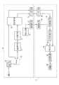
図2に本体ユニット11,レンズユニット12の構成を示す。本体ユニット11には、本体制御部30を設けてあり、レンズユニット12には、レンズ制御部31を設けてある。デジタルカメラ10は、撮影モード下ではこれら本体制御部30とレンズ制御部31とが協働して制御動作を行うことにより、撮影等の各種シーケンスが行われる。 FIG. 2 shows the configuration of the
レンズユニット12側のレンズ制御部31には、ROM31aと、RAM31bとを接続してある。ROM31aには、撮影モード・再生モード時に使用する制御プログラム等のプログラム等が予め記憶されている。レンズ制御部31は、本体ユニット11からの各種信号に応答し、ROM31aの制御プログラムに基づいてレンズユニット12の各部の駆動を制御する。 A
撮影レンズ13は、レンズ駆動部33によって駆動され、ズーミングやフォーカシング、絞りによるイメージセンサ14に入射する光量の調節を行う。この撮影レンズ13の背後に、イメージセンサ14を配してあり、撮影レンズ13による被写体像がイメージセンサ14の受光面に結像される。イメージセンサ14の受光面上には、多数の光電変換セルがマトリクス状に配されている。各光電変換セルは、入射した光をその光量に応じた電荷に変換して蓄積するフォトダイオードと、R(赤色),G(緑色),B(青色)のいずれかの色フィルタとからなる。 The
イメージセンサ14は、上記の各光電変換セルに入射する光を、その入射光量に応じた電荷に変換して蓄積することにより、被写体を撮影する。このイメージセンサ14は、タイミングジェネレータ34からの各種駆動信号により駆動され、撮影した被写体像をアナログ信号である画像信号として出力する。イメージセンサ14としては、例えばCCDイメージセンサを用いているが、それに限るものではなく、例えばMOS型のイメージセンサを用いてもよい。 The
イメージセンサ14からの画像信号は、アナログ信号処理部35に送られる。アナログ信号処理部35は、相関二重サンプリング回路やオートゲインコトローラからなり、入力される画像信号に対してノイズの除去,欠陥画素に対応する画像信号の補間処理,増幅処理を施して出力する。 The image signal from the
A/D変換器36は、アナログ信号処理部35からの画像信号をデジタル変換してRAWデータ形式の画像データ(以下、RAWデータという)を生成する。RAWデータのビット数は、再現しようとする階調数等によって所定のビット数に決められているが、JPEGモードで記録されるデータのビット数よりも大きく、例えば10〜16ビット程度である。 The A /
上記のアナログ信号処理部35,A/D変換器36は、タイミングジェネレータ34からのタイミング信号が入力されることによって、イメージセンサ14の動作に同期して作動する。 The analog
デジタル信号処理回部37は、RAWモード時には、A/D変換器36からのRAWデータに対して処理を施すことなく出力し、JPEGモード時には、入力されるRAWデータに対してオフセット補正処理、ホワイトバランスのためのパラメータ決定及びそのパラメータに基づくホワイトバランス補正処理、イメージセンサ14の色フィルタの特性に応じて色補正するためのリニアマトリクス演算処理、ガンマ補正処理,同時化処理、輪郭補正処理等からなる画像処理と、画像処理が施されたデータをYCデータに変換するYC変換処理とを行う。 In the RAW mode, the digital
AE/AF検出部38は、A/D変換器36からのRAWデータに基づいて被写体像の高周波成分の振幅値であるAF検出値と、被写体輝度を示すAE検出値を発生してレンズ制御部43に送る。レンズ制御部31は、被写体にピントを合致させるために、AF検出値が最大となるように撮影レンズ13のフォーカシングを行い、AE検出値に基づいて絞り値やイメージセンサ14の電子シャッタ速度(電荷蓄積時間)を決定し制御する。 The AE / AF detection unit 38 generates an AF detection value, which is an amplitude value of a high frequency component of the subject image, and an AE detection value indicating the subject luminance based on the RAW data from the A /
可逆圧縮部39は、RAWモード時にロスレスJPEG方式によってデータ圧縮を行う。このような可逆圧縮を行う回路は、作動時に非可逆圧縮に比べて回路規模が小さいので消費電力,発熱が小さい。このため、実装スペースの点で有利であるとともに、レンズユニット12の狭い空間に設けた場合の発熱による温度上昇も特に問題とならない。 The
情報生成部41は、撮影された画像の画素数,ホワイトバランスに必要なパラメータまたはレンズユニット12で行ったホワイトバランスの際のパラメータ、撮影レンズ13の仕様や特性等の撮影に関する情報を撮影情報として生成する。 The
電源部42は、マウント部16,18の接点を介して本体ユニット11から供給される電力をレンズユニット12の各部に給電する。この給電によって、レンズユニット12の各部が動作する。 The
レンズユニット12には、制御用シリアルドライバ43と、高速シリアルドライバ44とを設けてあり、これらはマウント部16,18の接点を介して本体ユニット11側の回路に接続される。制御用シリアルドライバ43は、本体制御部30とレンズ制御部31との間における制御コマンドの授受を行うために設けられている。高速シリアルドライバ44は、撮影情報と画像データ(RAWデータ,YCデータ)をレンズユニット12から本体ユニット11に転送するために設けられている。高速シリアルドライバ44は、画像データの転送時間を短くするために高速にデータ転送が可能なものが用いられ、制御用ドライバ43は、消費電力を低減するために高速シリアルドライバ44よりも転送速度が低いものを用いている。 The
レンズ制御部31,レンズ駆動部33,タイミングジェネレータ34,デジタル信号処理部37,AE/AF検出部38,可逆圧縮部41,情報生成部42,各シリアルドライバ43,44は、バス45を介して接続されており、これら各部はバス45を介してレンズ制御部31に制御されるとともに、相互間でデータの授受が可能になっている。 The
本体制御部30には、撮影モード・再生モード時に使用する制御プログラム等のプログラム等が予め記憶されたROM30aと、ワークメモリとして用いられるRAM30bとを接続してある。ROM30aには、撮影モード・再生モード時に使用する制御プログラム等のプログラム等が予め記憶されており、これに基づいて本体制御部30が作動する。 The main
操作部51は、本体ユニット11に設けたモード切替ダイヤル26等の各種操作部材から構成されており、それらの操作に応じた操作信号を発生し、その操作信号を本体制御部30に送る。本体制御部30は、レリーズボタン25の操作に応じたレリーズ信号と、操作部51からの操作信号とに応答して本体ユニット11の各部を制御するとともに、レンズ制御部31を介してレンズユニット12の動作を制御する。 The operation unit 51 includes various operation members such as a
レリーズボタン25が押圧操作された際に発生するレリーズ信号は、そのレリーズ操作から撮影のためのシーケンスの開始までできるだけ小さくするために、マウント部18,16の接点を介して直接にレンズ制御部31にも送られる。レンズ制御部31は、このレリーズ信号に応答して撮影シーケンスを実行する。 In order to minimize the release signal generated when the
バス52には、制御用シリアルドライバ53、高速シリアルドライバ54,I/O回路55,メモリ部56,ストロボ制御部57,LCDドライバ58,メディアコントローラ59,圧縮伸張部60,デジタル信号処理部61が接続されている。これら各部は、バス45を介して本体制御部30に制御されるとともに、相互間でデータの授受が可能になっている。 The
制御用シリアルドライバ53,高速シリアルドライバ54は、それぞれマウント部18,16の接点を介してレンズユニット12側の対応する制御用シリアルドライバ43,高速シリアルドライバ44と接続され、それぞれ協働してシリアル通信を行う。本体制御部30とレンズ制御部31との相互間の制御コマンド等の通信は、制御用シリアルドライバ43,53を介して行われ、画像データ,撮影情報の転送は、高速シリアルドライバ44,54を介して行われる。なお、撮影情報は、そのデータ量があまり大きくないので制御用シリアルドライバ43,53を介して転送してもよく、このようにすれば消費電力の低減を図ることができる。 The control
I/O回路55は、本体ユニット11にレンズユニット12が装着されているか否かを検出してそれに応じた装着信号を出力する。I/O回路55の入力端は、抵抗55aを介してプルアップされるとともに、マウント部18の本体側検出接点に接続してある。レンズユニット12側のマウント部16には、接地となるように接続されたレンズ側検出接点が設けてあり、レンズユニット12が正しく本体ユニット11に接続されたときには、各検出接点が接続されてI/O回路55の入力端がプルアップされたレベルから接地レベルとなることによって装着したことが検出される。 The I /
メモリ部56は、レンズユニット12から取得した画像データが一時的に書き込まれる。ストロボ制御部57は、本体制御部30からのストロボ発光信号に応答してストロボ発光部24を発光させる。LCDドライバ58には、YCデータが入力され、これをRGBデータに変換して本体ユニット11の背面に設けたLCD62を駆動することによって、そのLCD62にスルー画像表示や撮影済みの画像を表示する。 In the
メディアコントローラ59は、本体ユニット11に装着される記録媒体としてのメモリカード63に対して画像ファイルの読み書きを行う。画像ファイルは、圧縮されたRAWデータあるいはYCデータに撮影情報を結合したものになっている。撮影モードの場合には、レンズユニット12から取得した画像データと撮影情報とを用いて作成した画像ファイルがメモリカード63に記録される。再生モードの場合には、メモリカード63から読み出した画像ファイルから得られる画像データに伸張等の必要な処理を施してからLCDドライバ58に送ることでLCD62に記録されている画像が再生表示される。 The
圧縮伸張部60は、非可逆圧縮伸張回路60aと、可逆圧縮伸張回路60bとから構成される。非可逆圧縮伸張回路60aは、JPEGモード時にレンズユニット12からのYCデータをJPEG形式での非可逆圧縮し、また再生モード時にJPEG形式での非可逆圧縮されているYCデータの伸張を行う。可逆圧縮伸張回路60bは、画像データの可逆圧縮及び可逆圧縮されている画像の伸張を行うものであって、この例では再生モード時にRAWデータの画像を再生する際に、可逆圧縮されているRAWデータの伸張を行う。なお、この可逆圧縮伸張回路60bを用いて、例えばYCデータを非可逆圧縮する代わりに、可逆圧縮して記録する記録モードを設けてもよい。 The compression /
データ処理部61は、撮影モード下では、圧縮されたRAWデータまたはYCデータと撮影情報とを結合することにより画像ファイルを生成する。また、データ処理部61は、再生モード下では、伸張されたRAWデータに対してその撮影情報等に基づき、オフセット補正処理、ホワイトバランス補正処理、リニアマトリクス演算処理、ガンマ補正処理,同時化処理、輪郭補正処理,YC変換等を行い、LCDで画像を再生表示するためのYCデータを生成する。 The
本体ユニット11のバッテリ収納室(図示省略)にバッテリ64が装着され、このバッテリ64が電源制御部65に接続される。電源制御部65は、バッテリ64の出力電圧を所定の電圧に変圧し、本体ユニット11の各部に供給する。また、電源制御部65は、マウント部18,16の接点を介してレンズユニット12への給電を行う。この電源制御部65には、電源スイッチ66を接続してあり、各部への電力の供給と停止とは、電源スイッチ66のON/OFF操作に応答して制御される。 A
図3に機能ブロックを示すように、レリーズボタン25の全押し後にイメージセンサ14から出力される画像信号は、A/D変換器36が対応するデジタル変換手段70によってデジタル変換されてRAWデータとされる。データ経路制御手段71は、第1記録モードとしてのRAWモード時には、入力されるRAWデータを可逆圧縮手段72を介してデータ送信手段72に送り、第2記録モードとしてのJPEGモード時には、入力されるRAWデータを画像処理手段74,YC変換手段75を介してデータ送信手段72に送るようにデータの経路を切り換える。なお、第2記録モードにおいては、必ずしも得られるYCデータを圧縮して記録しなくてもよく、可逆圧縮して記録してもよい。 As shown in the functional block in FIG. 3, the image signal output from the
この実施形態においては、データ経路制御手段71は、RAWモード時にデジタル信号処理部37が入力されるRAWデータをそのままバス45に出力し、そのRAWデータを可逆圧縮部39が取得して圧縮してから高速シリアルドライバ44に送り、JPEGモード時には、デジタル信号処理部37が入力されるRAWデータに対して画像処理、YC変換処理を施してから高速シリアルドライバ44に送るように、レンズ制御部31が制御することに対応している。 In this embodiment, the data path control means 71 outputs the raw data input by the digital
可逆圧縮手段72は、RAWデータを可逆圧縮するものであり、可逆圧縮39に対応する。可逆圧縮手段72による、この実施形態では、ロスレスJPEG形式で可逆圧縮を行っているが、その他の可逆圧縮の形式を採用してもよい。 The lossless compression means 72 is for lossless compression of RAW data and corresponds to the
画像処理手段74は、RAWデータをYCデータに変換する際の前処理としての画像処理を行うためのものであり、デジタル信号処理部37によるRAWデータに対してオフセット補正処理、ホワイトバランス補正処理、リニアマトリクス演算処理、ガンマ補正処理,同時化処理、輪郭補正処理等の画像処理に対応する。この画像処理手段74による画像処理は、適宜に必要な処理を行えばよい。YC変換手段75は、RAWデータをYCデータに変換するためのものであり、デジタル信号処理部37による色差マトリクス演算処理に対応する。 The image processing means 74 is for performing image processing as preprocessing when converting RAW data into YC data. The digital
情報生成手段76は、撮影情報を生成して情報制御手段77に送る。情報生成手段76が生成する撮影情報としては、画素数,ホワイトバランスのパラメータ、撮影レンズ13の仕様や特性等の他にも、レンズユニット12で取得、生成可能な撮影に関する各種情報を採用することができる。この情報生成手段76は、情報生成部41に対応する。 The
データ送信手段73は、画像データとして可逆圧縮手段72からで可逆圧縮されたRAWデータまたはYC変換手段37からのYCデータを本体ユニット11に送り、データ受信手段81はその画像データを受信する。また、情報制御手段77は、情報生成手段76で生成された撮影情報を本体ユニット11に送り、情報受信手段82は、その撮影情報を受信する。データ送信手段73,情報送信手段77は、いずれもレンズユニット12の高速シリアルドライバ44に対応し、データ受信手段81,情報受信手段82は、いずれも本体ユニット11の高速シリアルドライバ54に対応する。なお、制御用シリアルドライバ43,53を用いて撮影情報を転送する場合には、情報送信手段77,情報受信手段は、制御用シリアルドライバ43,53に対応する。情報制御手段77は、情報生成手段76で生成された撮影情報を本体ユニット11に送り、情報受信手段82は、その撮影情報を受信する。また、データ送信手段73とデータ受信手段81,情報送信手段77と情報受信手段82は、いずれもリアル通信を行うようにしているが、通信の形式等はこれに限られるものではない。 The data transmission means 73 sends RAW data reversibly compressed by the reversible compression means 72 or YC data from the YC conversion means 37 to the
非可逆圧縮手段83は、JPEGモード時に転送されてくるYCデータを非可逆圧縮形式でデータ圧縮する。非可逆圧縮手段73は、この例では非可逆圧縮伸張回路60aに対応しており非可逆のJPEG形式で圧縮を行うが、非可逆圧縮の形式はこれに限られるものではない。 The irreversible compression means 83 compresses the YC data transferred in the JPEG mode in the irreversible compression format. In this example, the irreversible compression means 73 corresponds to the irreversible compression /
付加手段84は、RAWモード時では可逆圧縮されたRAWデータに撮影情報を結合して画像ファイルを作成し、JPEGモード時では非可逆圧縮されたYCデータに撮影情報を結合して画像ファイルを作成する。この付加手段は、データ処理部61に対応する。なお、レンズユニット12で生成された撮影情報に加えて、付加手段84が本体ユニット11に固有の情報を加えるように構成してもよい。また、撮影情報等を付加しない画像データを記録媒体86に記録するようにしてもよい。さらには、レンズユニット12で撮影情報をRAWデータに付加した後に本体ユニット11に転送してもよい。 The adding
記録制御手段85は、メディアコントローラ59に対応するものであり、付加手段84で作成された画像ファイルを記憶媒体86に記録する。記録媒体86は、メモリカード63に対応するが、記録媒体76としては、メモリカードに限られるものではなく、光学的あるいは磁気的に記録する例えばディスクであってもよく、本体ユニット11に内蔵したメモリ等であってもよい。 The
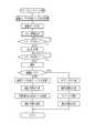
次に、上記構成の作用について図4,図5を参照しながら説明する。なお、図4は、本体ユニット11側のシーケンスの概略を示しており、図5は、レンズユニット12側のシーケンスの概略を示している。 Next, the operation of the above configuration will be described with reference to FIGS. 4 shows the outline of the sequence on the
デジタルカメラ10を使用するには、レンズユニット12を本体ユニット11に取り付けてから、電源スイッチ66をONにする。電源スイッチ66をONにすると、バッテリ64の電圧が電源制御部65によって変圧され、本体ユニット11の各部に供給される。また、この電源制御部65から各マウント部18,16の接点を介してレンズユニット12の電源部42にも電力が供給される。そして、この電源部42によってレンズユニット12の各部に電力が供給される。これにより、デジタルカメラ10が起動する。 In order to use the digital camera 10, the
撮影を行う場合には、上記のようにしてデジタルカメラ10を起動させた後、モード切替ダイヤル26を操作して撮影モードを選択すると同時にRAWモードまたはJPEGモードを選択する。記録モードが選択されると、その選択された記録モードが本体制御部30によって本体ユニットに設定される。また、本体制御部30によって、選択された記録モードが制御用シリアルドライバ53,43を介してレンズ制御部31に送られてレンズユニット12に設定される。 When shooting, after starting the digital camera 10 as described above, the
記録モードにかかわらず撮影モードとなると、スルー画像表示が行われる。イメージセンサ14によって被写体のスルー画像表示のための光電変換が繰り返し行われ、得られる画像信号がアナログ信号処理部35での処理を施されてから、A/D変換器36によってRAWデータに変換される。そして、このRAWデータがデジタル信号処理部37で画像処理が施されてからYCデータに変換される。そして、このようにして得られるYCデータが高速シリアルドライバ44,54を介して本体ユニット11に送られる。なお、スルー画像表示の際には、例えばイメージセンサ14での電荷転送を制御して画素混合や間引き等を行うことにより、画素数が少なくされている。 When the shooting mode is set regardless of the recording mode, a through image display is performed. The
本体ユニット11に送られたYCデータは、バス52を介してメモリ部56に書き込まれた後、LCDドライバ58によって読み出され、それに基づいてLCD62が駆動される。メモリ部56のYCデータは、イメージセンサ14によって1フレーム分の撮影が行われるごとに更新されるから、被写体がスルー画像としてLCD62に表示される。撮影者は、このLCD62に表示されるスルー画像を観察することによってフレーミングを行うことができる。 The YC data sent to the
フレーミングの後、レリーズボタン25を半押しとすると、それに応じたレリーズ信号(以下、半押し信号という)が本体制御部30と、レンズ制御部31にそれぞれ送られる。本体制御部30は、この半押し信号が入力されると、レリーズボタン25の全押しを待った状態となる。一方、レンズ制御部31に半押し信号が入力されると、AE/AF検出部38からのAF検出値が最大になるように撮影レンズ13を駆動してフォーカシングを行い、またAE検出値に基づいて絞り値とイメージセンサ14の電子シャッタ速度を決定する。 When the
レリーズボタン25をさらに押し込んで全押しとすると、そのレリーズ信号(以下、全押し信号という)が本体制御部30及びレンズ制御部31にそれぞれ入力される。そして、この全押し信号に応答して、レンズ制御部31によってレンズユニット12の各部が静止画を撮影するために制御される。これにより、撮影レンズ13の絞りが半押し時に決定した絞り値となるようにした後に、イメージセンサ14が駆動されて1画面分の露光(電荷蓄積)を行う。露光完了後、イメージセンサ14からの1画面分の画像信号がアナログ信号処理部35に入力され、ノイズ除去、増幅等が行われた後にA/D変換器36によってRAWデータに変換される。 When the
例えば記録モードとして、JPEGモードが設定されている場合には、A/D変換器36からのRAWデータは、デジタル信号処理部37で各種の画像処理が施された後に、YC変換処理によりYCデータに変換される。このようにして得られる1画面分のYCデータは、高速シリアルドライバ44,54によって本体ユニット11に順次に転送されメモリ部56に書き込まれる。 For example, when the JPEG mode is set as the recording mode, the RAW data from the A /
このようにして1画面分のYCデータがメモリ部56に書き込まれると、それが非可逆圧縮回路60aによって読み出されて、非可逆なJPEG形式で圧縮されてメモリ部56に書き込まれる。 When YC data for one screen is written in the
また、露光完了後には、情報生成部39によって、撮影された画像の画素数,ホワイトバランスの際のパラメータ等の撮影情報が生成され、これが高速シリアルドライバ44,54を介して本体ユニット11に送られ、メモリ部56に書き込まれる。なお、この撮影情報の転送は、前述のように制御用シリアルドライバ43,53を用いて転送してもよい。また、YCデータと撮影情報との転送順番はどちらが先であってもよい。 After the exposure is completed, the
上記のように、非可逆圧縮されたYCデータと、撮影情報とがメモリ部56に書き込まれた状態になると、データ処理部61によって、メモリ部56上で撮影情報と非可逆圧縮されたYCデータとを結合した画像ファイルが作成される。そして、この画像ファイルが本体制御部30によってメモリ部56からメディアコントローラ59に転送され、メモリカード63に画像ファイルが記録される。 As described above, when the irreversibly compressed YC data and the photographic information are written in the
一方、記録モードとしてRAWモードが設定されている場合には、A/D変換器36からのRAWデータは、デジタル信号処理部37を画像処理,YC変換処理が施されることなく、可逆圧縮部39に送られ、可逆圧縮される。そして、この可逆圧縮されたRAWデータが高速シリアルドライバ44,54によって本体ユニット11に順次に転送されてメモリ部56に書き込まれる。情報生成部39によって生成された撮影情報が高速シリアルドライバ44,54を介して本体ユニット11に送られ、メモリ部56に書き込まれる。なお、この場合にも、撮影情報の転送は制御用シリアルドライバ43,53を用いて転送してもよく、可逆圧縮されたRAWデータと撮影情報とがどちらが先に転送されてもよい。 On the other hand, when the RAW mode is set as the recording mode, the RAW data from the A /
このようにRAWデータの転送を行うが、圧縮前のRAWデータは、YCデータなどに比べてかなり大きなデータ量となるが、可逆圧縮によってデ−タ量が小さくされたRAWデータを転送するので、短時間で転送できるとともに、転送にともなう高速シリアルドライバ44の発熱が問題にならない。また、可逆圧縮なので、色情報などの画像の情報が失われることはない。 Although RAW data is transferred in this way, RAW data before compression has a considerably large data amount compared to YC data or the like, but RAW data whose data amount has been reduced by lossless compression is transferred. The data can be transferred in a short time, and the heat generated by the high-speed
上記のように、可逆圧縮されたRAWデータと撮影情報とがメモリ部56に書き込まれた状態になると、データ処理部61によって、それら撮影情報と可逆圧縮されたRAWデータとが結合されて画像ファイルが作成される。そして、この画像ファイルが本体制御部30によってメモリ部56からメディアコントローラ59に転送され、メモリカード63に画像ファイルが記録される。 As described above, when the losslessly compressed RAW data and shooting information are written in the
図6ないし図8は、RAWデータと同様に、YCデータに可逆圧縮を施してから、本体ユニットに転送する例を示すものである。なお、以下に詳細を説明するように、YCデータに対して、レンズユニット側で可逆圧縮を行い、本体ユニット側で可逆圧縮されたYCデータに伸張処理を行ってから非可逆圧縮する点で異なる他は、上記実施形態と同じであり、実質的に同じ部材には同一の符号を付してその説明を省略する。また、図6はこの例を機能ブロックで示すものであり、図7本体ユニット11側のシーケンスの概略を示しており、図8はレンズユニット12側のシーケンスの概略を示している。 6 to 8 show an example in which YC data is subjected to lossless compression and transferred to the main unit in the same manner as RAW data. Note that, as will be described in detail below, YC data is subjected to lossless compression on the lens unit side, and the lossy compression is performed after decompression processing is performed on the YC data that has been losslessly compressed on the main unit side. Others are the same as the above embodiment, and substantially the same members are denoted by the same reference numerals, and the description thereof is omitted. FIG. 6 shows this example as a functional block, showing an outline of the sequence on the
データ経路制御手段91は、第2記録モードとしてのJPEGモード時に、入力されるRAWデータを画像処理手段74,YC変換手段75,可逆圧縮手段72を介してデータ送信手段72に送るようにデータの経路を切り換える。すなわち、JPEGモード時には、デジタル信号処理部37からのYCデータが可逆圧縮部39で可逆圧縮されてから各高速シリアルドライバ44,54本体ユニット11に送られる。本体ユニット11では、可逆圧縮されたYCデータを可逆圧縮伸張回路60bが対応する可逆伸張手段92で伸張した後に、その伸張したYCデータを非可逆圧縮手段73によって非可逆なJPEG形式でデータ圧縮する。 In the JPEG mode as the second recording mode, the data path control
これによれば、レンズユニット12から本体ユニット11にYCデータを転送する際に、転送されるデータ量が少なくなるから、より短時間で転送できるとともに、転送にともなう高速シリアルドライバ44の発熱をより少なくすることができる。 According to this, when transferring YC data from the
10 デジタルカメラ
11 本体ユニット
12 レンズユニット
13 撮影レンズ
14 イメージセンサ
26 モード切替ダイヤル
36 A/D変換器
37 デジタル信号処理部
39 可逆圧縮部
43,44,53,54 シリアルドライバ
59 メディアコントローラ
60b 可逆圧縮伸張回路
61 データ処理部
63 メモリカードDESCRIPTION OF SYMBOLS 10
Claims (9)
Translated fromJapanese前記本体ユニットまたはレンズユニットの一方に、RAWデータ形式の画像データを前記記録媒体に記録する第1記録モードと輝度及び各色差の画像データを前記記録媒体に記録する第2記録モードとを選択する選択手段及びこの選択手段によって選択された記録モードを各ユニットに設定するモード設定手段を有し、
前記レンズユニットは、
イメージセンサから出力されるアナログ信号をデジタル変換することでRAWデータ形式の画像データを生成するデジタル変換手段と、
画像データを可逆圧縮する可逆圧縮手段と、
RAWデータ形式の画像データを輝度及び各色差の画像データに変換するYC変換手段と、
画像データを前記本体ユニットに送信するデータ送信手段と、
第1記録モードが設定されているときに、前記デジタル変換手段からのRAWデータ形式の画像データを前記可逆圧縮手段を介して前記データ送信手段に送り、第2記録モードが設定されているときに、前記デジタル変換手段からのRAWデータ形式の画像データを前記YC変換手段を介してデータ送信手段に送るデータ経路制御手段とを有し、
前記本体ユニットは、
前記データ送信手段からの画像データを受信する受信手段と、
第2記録モードが設定されているときに、輝度及び各色差の画像データを非可逆圧縮する非可逆圧縮手段と、
第1記録モードが設定されているときに、前記データ受信手段によって受信した可逆圧縮されたRAWデータ形式の画像データを記録媒体に記録し、第2記録モードが設定されているときに、前記データ受信手段によって受信され、前記非可逆圧縮手段によって非可逆圧縮された輝度及び各色差の画像データを前記記録媒体に記録する記録制御手段とを有することを特徴とする撮影装置。A lens unit having a taking lens and the image sensor, the lens unit is detachable, in the imaging apparatus comprisinga main unit to be recorded on the recording medium by receiving the image data from the mounted lens unit,
A first recording mode for recording image data in RAW data format on the recording medium and a second recording mode for recording image data of luminance and each color difference on the recording medium are selected on one of the main unit or the lens unit. A selection means and a mode setting means for setting the recording mode selected by the selection means in each unit;
The lens unit is
Digital conversion means for generating image data in the RAW data format by digitally converting an analog signal output from the image sensor;
Reversible compression means for reversibly compressing image data;
YC conversion means for converting image data in RAW data format into image data of luminance and each color difference;
Data transmission means for transmitting theimages data to said mainunit,
When the first recording mode is set, image data in the RAW data format from the digital conversion means is sent to the data transmission means via the lossless compression means, and when the second recording mode is set A data path control means for sending image data in the RAW data format from the digital conversion means to the data transmission means via the YC conversion means ,
The main unit is
Receiving means for receiving image data from the data transmitting means;
Irreversible compression means for irreversibly compressing image data of luminance and each color difference when the second recording mode is set;
When the first recording mode is set, the reversibly compressed RAW data format image data received by the data receiving means is recorded on a recording medium, and when the second recording mode is set, the data An imaging apparatuscomprising: a recording control unit that recordsimage data of luminance and each color difference received by the receiving unit and irreversibly compressed by the irreversible compressing unit on the recording medium.
前記本体ユニットは、前記レンズユニットで可逆圧縮された輝度及び各色差の画像データを伸張する可逆伸張手段を有し、
前記非可逆圧縮手段は、前記可逆伸張手段で伸張された輝度及び各色差の画像データを非可逆圧縮することを特徴とする請求項1記載の撮影装置。The data path control means,when the second recording mode is set, sending the image data of the RAW data format from said digital converting means tosaid data transmission means via the YC converting means andsaid lossless compression meansThe
The main body unit has reversible decompression means for decompressing the image data of luminance and each color difference reversibly compressed by the lens unit,
The photographing apparatus according to claim 1, wherein the irreversible compression unit irreversibly compresses the image data of luminance and each color difference expanded by the reversible expansion unit.
前記本体ユニットは、情報送信手段からの撮影情報を受信する情報受信手段と、撮影情報を画像データに付加する付加手段とを有し、
前記記録制御手段は、撮影情報が付加された画像データを記録媒体に記録することを特徴とする請求項1または2記載の撮影装置。The lens unit includes information generation means for generating shooting information relating to shooting, and information transmission means for transmitting the shooting information to the main unit.
The main unit has information receiving means for receiving shooting information from the information transmitting means, and adding means for adding shooting information to image data,
3. The photographing apparatus according to claim 1, wherein the recording control unit records image data to which photographing information is added on a recording medium.
Priority Applications (1)
| Application Number | Priority Date | Filing Date | Title |
|---|---|---|---|
| JP2006081569AJP4615468B2 (en) | 2006-03-23 | 2006-03-23 | Imaging device |
Applications Claiming Priority (1)
| Application Number | Priority Date | Filing Date | Title |
|---|---|---|---|
| JP2006081569AJP4615468B2 (en) | 2006-03-23 | 2006-03-23 | Imaging device |
Publications (2)
| Publication Number | Publication Date |
|---|---|
| JP2007259136A JP2007259136A (en) | 2007-10-04 |
| JP4615468B2true JP4615468B2 (en) | 2011-01-19 |
Family
ID=38632905
Family Applications (1)
| Application Number | Title | Priority Date | Filing Date |
|---|---|---|---|
| JP2006081569AExpired - Fee RelatedJP4615468B2 (en) | 2006-03-23 | 2006-03-23 | Imaging device |
Country Status (1)
| Country | Link |
|---|---|
| JP (1) | JP4615468B2 (en) |
Families Citing this family (57)
| Publication number | Priority date | Publication date | Assignee | Title |
|---|---|---|---|---|
| JP5258355B2 (en)* | 2008-04-03 | 2013-08-07 | キヤノン株式会社 | Imaging apparatus and driving method thereof |
| US8866920B2 (en) | 2008-05-20 | 2014-10-21 | Pelican Imaging Corporation | Capturing and processing of images using monolithic camera array with heterogeneous imagers |
| DK3876510T3 (en) | 2008-05-20 | 2024-11-11 | Adeia Imaging Llc | CAPTURE AND PROCESSING OF IMAGES USING MONOLITHIC CAMERA ARRAY WITH HETEROGENEOUS IMAGES |
| US11792538B2 (en) | 2008-05-20 | 2023-10-17 | Adeia Imaging Llc | Capturing and processing of images including occlusions focused on an image sensor by a lens stack array |
| JP5238365B2 (en)* | 2008-06-05 | 2013-07-17 | 富士フイルム株式会社 | Imaging device |
| EP2502115A4 (en) | 2009-11-20 | 2013-11-06 | Pelican Imaging Corp | CAPTURE AND IMAGE PROCESSING USING A MONOLITHIC CAMERAS NETWORK EQUIPPED WITH HETEROGENEOUS IMAGERS |
| US8928793B2 (en) | 2010-05-12 | 2015-01-06 | Pelican Imaging Corporation | Imager array interfaces |
| US8878950B2 (en) | 2010-12-14 | 2014-11-04 | Pelican Imaging Corporation | Systems and methods for synthesizing high resolution images using super-resolution processes |
| EP2708019B1 (en)* | 2011-05-11 | 2019-10-16 | FotoNation Limited | Systems and methods for transmitting and receiving array camera image data |
| US20130070060A1 (en) | 2011-09-19 | 2013-03-21 | Pelican Imaging Corporation | Systems and methods for determining depth from multiple views of a scene that include aliasing using hypothesized fusion |
| CN104081414B (en) | 2011-09-28 | 2017-08-01 | Fotonation开曼有限公司 | Systems and methods for encoding and decoding light field image files |
| EP2817955B1 (en) | 2012-02-21 | 2018-04-11 | FotoNation Cayman Limited | Systems and methods for the manipulation of captured light field image data |
| US9210392B2 (en) | 2012-05-01 | 2015-12-08 | Pelican Imaging Coporation | Camera modules patterned with pi filter groups |
| JP2015534734A (en) | 2012-06-28 | 2015-12-03 | ペリカン イメージング コーポレイション | System and method for detecting defective camera arrays, optical arrays, and sensors |
| US20140002674A1 (en) | 2012-06-30 | 2014-01-02 | Pelican Imaging Corporation | Systems and Methods for Manufacturing Camera Modules Using Active Alignment of Lens Stack Arrays and Sensors |
| PL4296963T3 (en) | 2012-08-21 | 2025-04-28 | Adeia Imaging Llc | Method for depth detection in images captured using array cameras |
| WO2014032020A2 (en) | 2012-08-23 | 2014-02-27 | Pelican Imaging Corporation | Feature based high resolution motion estimation from low resolution images captured using an array source |
| EP4307659A1 (en) | 2012-09-28 | 2024-01-17 | Adeia Imaging LLC | Generating images from light fields utilizing virtual viewpoints |
| WO2014078443A1 (en) | 2012-11-13 | 2014-05-22 | Pelican Imaging Corporation | Systems and methods for array camera focal plane control |
| US9462164B2 (en) | 2013-02-21 | 2016-10-04 | Pelican Imaging Corporation | Systems and methods for generating compressed light field representation data using captured light fields, array geometry, and parallax information |
| US9374512B2 (en) | 2013-02-24 | 2016-06-21 | Pelican Imaging Corporation | Thin form factor computational array cameras and modular array cameras |
| US9774789B2 (en) | 2013-03-08 | 2017-09-26 | Fotonation Cayman Limited | Systems and methods for high dynamic range imaging using array cameras |
| US8866912B2 (en) | 2013-03-10 | 2014-10-21 | Pelican Imaging Corporation | System and methods for calibration of an array camera using a single captured image |
| US9888194B2 (en) | 2013-03-13 | 2018-02-06 | Fotonation Cayman Limited | Array camera architecture implementing quantum film image sensors |
| WO2014165244A1 (en) | 2013-03-13 | 2014-10-09 | Pelican Imaging Corporation | Systems and methods for synthesizing images from image data captured by an array camera using restricted depth of field depth maps in which depth estimation precision varies |
| US9124831B2 (en) | 2013-03-13 | 2015-09-01 | Pelican Imaging Corporation | System and methods for calibration of an array camera |
| US9106784B2 (en) | 2013-03-13 | 2015-08-11 | Pelican Imaging Corporation | Systems and methods for controlling aliasing in images captured by an array camera for use in super-resolution processing |
| US9578259B2 (en) | 2013-03-14 | 2017-02-21 | Fotonation Cayman Limited | Systems and methods for reducing motion blur in images or video in ultra low light with array cameras |
| WO2014153098A1 (en) | 2013-03-14 | 2014-09-25 | Pelican Imaging Corporation | Photmetric normalization in array cameras |
| US10122993B2 (en) | 2013-03-15 | 2018-11-06 | Fotonation Limited | Autofocus system for a conventional camera that uses depth information from an array camera |
| US9497429B2 (en) | 2013-03-15 | 2016-11-15 | Pelican Imaging Corporation | Extended color processing on pelican array cameras |
| US9445003B1 (en) | 2013-03-15 | 2016-09-13 | Pelican Imaging Corporation | Systems and methods for synthesizing high resolution images using image deconvolution based on motion and depth information |
| US9438888B2 (en) | 2013-03-15 | 2016-09-06 | Pelican Imaging Corporation | Systems and methods for stereo imaging with camera arrays |
| US9898856B2 (en) | 2013-09-27 | 2018-02-20 | Fotonation Cayman Limited | Systems and methods for depth-assisted perspective distortion correction |
| US9264592B2 (en) | 2013-11-07 | 2016-02-16 | Pelican Imaging Corporation | Array camera modules incorporating independently aligned lens stacks |
| US10119808B2 (en) | 2013-11-18 | 2018-11-06 | Fotonation Limited | Systems and methods for estimating depth from projected texture using camera arrays |
| WO2015081279A1 (en) | 2013-11-26 | 2015-06-04 | Pelican Imaging Corporation | Array camera configurations incorporating multiple constituent array cameras |
| US10089740B2 (en) | 2014-03-07 | 2018-10-02 | Fotonation Limited | System and methods for depth regularization and semiautomatic interactive matting using RGB-D images |
| JP2017531976A (en) | 2014-09-29 | 2017-10-26 | フォトネイション ケイマン リミテッド | System and method for dynamically calibrating an array camera |
| US9942474B2 (en) | 2015-04-17 | 2018-04-10 | Fotonation Cayman Limited | Systems and methods for performing high speed video capture and depth estimation using array cameras |
| US10482618B2 (en) | 2017-08-21 | 2019-11-19 | Fotonation Limited | Systems and methods for hybrid depth regularization |
| US11270110B2 (en) | 2019-09-17 | 2022-03-08 | Boston Polarimetrics, Inc. | Systems and methods for surface modeling using polarization cues |
| WO2021071992A1 (en) | 2019-10-07 | 2021-04-15 | Boston Polarimetrics, Inc. | Systems and methods for augmentation of sensor systems and imaging systems with polarization |
| DE112020005932T5 (en) | 2019-11-30 | 2023-01-05 | Boston Polarimetrics, Inc. | SYSTEMS AND METHODS FOR SEGMENTATION OF TRANSPARENT OBJECTS USING POLARIZATION CHARACTERISTICS |
| EP4081933A4 (en) | 2020-01-29 | 2024-03-20 | Intrinsic Innovation LLC | Systems and methods for characterizing object pose detection and measurement systems |
| US11797863B2 (en) | 2020-01-30 | 2023-10-24 | Intrinsic Innovation Llc | Systems and methods for synthesizing data for training statistical models on different imaging modalities including polarized images |
| US11953700B2 (en) | 2020-05-27 | 2024-04-09 | Intrinsic Innovation Llc | Multi-aperture polarization optical systems using beam splitters |
| US12069227B2 (en) | 2021-03-10 | 2024-08-20 | Intrinsic Innovation Llc | Multi-modal and multi-spectral stereo camera arrays |
| US12020455B2 (en) | 2021-03-10 | 2024-06-25 | Intrinsic Innovation Llc | Systems and methods for high dynamic range image reconstruction |
| US11954886B2 (en) | 2021-04-15 | 2024-04-09 | Intrinsic Innovation Llc | Systems and methods for six-degree of freedom pose estimation of deformable objects |
| US11290658B1 (en) | 2021-04-15 | 2022-03-29 | Boston Polarimetrics, Inc. | Systems and methods for camera exposure control |
| US12067746B2 (en) | 2021-05-07 | 2024-08-20 | Intrinsic Innovation Llc | Systems and methods for using computer vision to pick up small objects |
| US12175741B2 (en) | 2021-06-22 | 2024-12-24 | Intrinsic Innovation Llc | Systems and methods for a vision guided end effector |
| US12340538B2 (en) | 2021-06-25 | 2025-06-24 | Intrinsic Innovation Llc | Systems and methods for generating and using visual datasets for training computer vision models |
| US12172310B2 (en) | 2021-06-29 | 2024-12-24 | Intrinsic Innovation Llc | Systems and methods for picking objects using 3-D geometry and segmentation |
| US11689813B2 (en) | 2021-07-01 | 2023-06-27 | Intrinsic Innovation Llc | Systems and methods for high dynamic range imaging using crossed polarizers |
| US12293535B2 (en) | 2021-08-03 | 2025-05-06 | Intrinsic Innovation Llc | Systems and methods for training pose estimators in computer vision |
Family Cites Families (6)
| Publication number | Priority date | Publication date | Assignee | Title |
|---|---|---|---|---|
| JP3630879B2 (en)* | 1996-10-11 | 2005-03-23 | キヤノン株式会社 | Video camera |
| JP2001038965A (en)* | 1999-07-29 | 2001-02-13 | Asahi Optical Co Ltd | Printer color adjustment device |
| JP4513205B2 (en)* | 2000-12-20 | 2010-07-28 | 株式会社ニコン | Electronic camera and recording medium for image processing program |
| JP4065482B2 (en)* | 2001-09-18 | 2008-03-26 | キヤノン株式会社 | Image data processing method, apparatus, storage medium, and program |
| JP2005167862A (en)* | 2003-12-05 | 2005-06-23 | Fuji Photo Film Co Ltd | Imaging device and point sequential image data reproducing device, and control method of them |
| JP4451181B2 (en)* | 2004-03-26 | 2010-04-14 | オリンパス株式会社 | Image compression method and image compression apparatus |
- 2006
- 2006-03-23JPJP2006081569Apatent/JP4615468B2/ennot_activeExpired - Fee Related
Also Published As
| Publication number | Publication date |
|---|---|
| JP2007259136A (en) | 2007-10-04 |
Similar Documents
| Publication | Publication Date | Title |
|---|---|---|
| JP4615468B2 (en) | Imaging device | |
| JP4301308B2 (en) | Imaging apparatus and image processing method | |
| JP3945052B2 (en) | Interchangeable lens electronic camera, interchangeable lens unit and camera body | |
| US20070132878A1 (en) | Digital camera system | |
| JP2008219428A (en) | Imaging device | |
| JP4764854B2 (en) | Imaging apparatus, image reproducing apparatus, imaging method, system, and program | |
| JP2000050129A (en) | Digital camera | |
| JP2005117395A (en) | Imaging device | |
| JP2008294668A (en) | Imaging apparatus and control method thereof | |
| JPH11308562A (en) | Digital camera system | |
| JP2008258981A (en) | Imaging apparatus, control method therefor, and program | |
| JP2000253293A (en) | Digital camera | |
| JP3734069B2 (en) | Digital camera and its system | |
| JP3807007B2 (en) | Accessories for digital cameras | |
| JP2002209125A (en) | Digital camera | |
| JP2009005356A (en) | Imaging apparatus, image processing apparatus, image processing system, image processing method, and image processing program | |
| JP2007325211A (en) | Digital camera | |
| JP4794726B2 (en) | Electronic camera and printer | |
| JP4605400B2 (en) | Image output system, image generation apparatus, and image generation method | |
| JP4400953B2 (en) | Print control device | |
| JP4692971B2 (en) | Shooting system | |
| JP3716181B2 (en) | Digital camera | |
| JP4912680B2 (en) | Camera system, camera and external flash | |
| JP4416691B2 (en) | Communication information transfer method | |
| JP2007166024A (en) | Imaging apparatus and control method thereof |
Legal Events
| Date | Code | Title | Description |
|---|---|---|---|
| A621 | Written request for application examination | Free format text:JAPANESE INTERMEDIATE CODE: A621 Effective date:20080716 | |
| A977 | Report on retrieval | Free format text:JAPANESE INTERMEDIATE CODE: A971007 Effective date:20100615 | |
| A131 | Notification of reasons for refusal | Free format text:JAPANESE INTERMEDIATE CODE: A131 Effective date:20100721 | |
| A521 | Request for written amendment filed | Free format text:JAPANESE INTERMEDIATE CODE: A523 Effective date:20100831 | |
| TRDD | Decision of grant or rejection written | ||
| A01 | Written decision to grant a patent or to grant a registration (utility model) | Free format text:JAPANESE INTERMEDIATE CODE: A01 Effective date:20100922 | |
| A01 | Written decision to grant a patent or to grant a registration (utility model) | Free format text:JAPANESE INTERMEDIATE CODE: A01 | |
| A61 | First payment of annual fees (during grant procedure) | Free format text:JAPANESE INTERMEDIATE CODE: A61 Effective date:20101020 | |
| R150 | Certificate of patent or registration of utility model | Free format text:JAPANESE INTERMEDIATE CODE: R150 | |
| FPAY | Renewal fee payment (event date is renewal date of database) | Free format text:PAYMENT UNTIL: 20131029 Year of fee payment:3 | |
| R250 | Receipt of annual fees | Free format text:JAPANESE INTERMEDIATE CODE: R250 | |
| R250 | Receipt of annual fees | Free format text:JAPANESE INTERMEDIATE CODE: R250 | |
| LAPS | Cancellation because of no payment of annual fees |