JP4614067B2 - How to delete a vehicle window - Google Patents
How to delete a vehicle windowDownload PDFInfo
- Publication number
- JP4614067B2 JP4614067B2JP2004572170AJP2004572170AJP4614067B2JP 4614067 B2JP4614067 B2JP 4614067B2JP 2004572170 AJP2004572170 AJP 2004572170AJP 2004572170 AJP2004572170 AJP 2004572170AJP 4614067 B2JP4614067 B2JP 4614067B2
- Authority
- JP
- Japan
- Prior art keywords
- wire
- window element
- side window
- adhesive
- tool
- Prior art date
- Legal status (The legal status is an assumption and is not a legal conclusion. Google has not performed a legal analysis and makes no representation as to the accuracy of the status listed.)
- Expired - Fee Related
Links
- 238000000034methodMethods0.000claimsabstractdescription30
- 238000005520cutting processMethods0.000claimsabstractdescription21
- 239000000853adhesiveSubstances0.000claimsabstractdescription19
- 230000001070adhesive effectEffects0.000claimsabstractdescription19
- 230000007246mechanismEffects0.000claimsdescription27
- 238000004804windingMethods0.000claimsdescription8
- 230000001066destructive effectEffects0.000abstractdescription2
- 238000004026adhesive bondingMethods0.000abstract1
- 238000003780insertionMethods0.000description9
- 230000037431insertionEffects0.000description9
- 230000001154acute effectEffects0.000description3
- 238000012986modificationMethods0.000description3
- 230000004048modificationEffects0.000description3
- 238000013461designMethods0.000description2
- 239000002184metalSubstances0.000description2
- 238000005452bendingMethods0.000description1
- 238000004140cleaningMethods0.000description1
- 238000010586diagramMethods0.000description1
- 238000011017operating methodMethods0.000description1
- 238000010422paintingMethods0.000description1
- 239000000565sealantSubstances0.000description1
- 238000001179sorption measurementMethods0.000description1
Images


Classifications
- B—PERFORMING OPERATIONS; TRANSPORTING
- B25—HAND TOOLS; PORTABLE POWER-DRIVEN TOOLS; MANIPULATORS
- B25B—TOOLS OR BENCH DEVICES NOT OTHERWISE PROVIDED FOR, FOR FASTENING, CONNECTING, DISENGAGING OR HOLDING
- B25B11/00—Work holders not covered by any preceding group in the subclass, e.g. magnetic work holders, vacuum work holders
- B25B11/005—Vacuum work holders
- B25B11/007—Vacuum work holders portable, e.g. handheld
- B—PERFORMING OPERATIONS; TRANSPORTING
- B26—HAND CUTTING TOOLS; CUTTING; SEVERING
- B26B—HAND-HELD CUTTING TOOLS NOT OTHERWISE PROVIDED FOR
- B26B27/00—Hand cutting tools not provided for in the preceding groups, e.g. finger rings for cutting string, devices for cutting by means of wires
- B26B27/002—Tools using wires as cutting means
- B—PERFORMING OPERATIONS; TRANSPORTING
- B26—HAND CUTTING TOOLS; CUTTING; SEVERING
- B26D—CUTTING; DETAILS COMMON TO MACHINES FOR PERFORATING, PUNCHING, CUTTING-OUT, STAMPING-OUT OR SEVERING
- B26D1/00—Cutting through work characterised by the nature or movement of the cutting member or particular materials not otherwise provided for; Apparatus or machines therefor; Cutting members therefor
- B26D1/01—Cutting through work characterised by the nature or movement of the cutting member or particular materials not otherwise provided for; Apparatus or machines therefor; Cutting members therefor involving a cutting member which does not travel with the work
- B26D1/547—Cutting through work characterised by the nature or movement of the cutting member or particular materials not otherwise provided for; Apparatus or machines therefor; Cutting members therefor involving a cutting member which does not travel with the work having a wire-like cutting member
- B—PERFORMING OPERATIONS; TRANSPORTING
- B62—LAND VEHICLES FOR TRAVELLING OTHERWISE THAN ON RAILS
- B62D—MOTOR VEHICLES; TRAILERS
- B62D67/00—Systematic disassembly of vehicles for recovery of salvageable components, e.g. for recycling
- Y—GENERAL TAGGING OF NEW TECHNOLOGICAL DEVELOPMENTS; GENERAL TAGGING OF CROSS-SECTIONAL TECHNOLOGIES SPANNING OVER SEVERAL SECTIONS OF THE IPC; TECHNICAL SUBJECTS COVERED BY FORMER USPC CROSS-REFERENCE ART COLLECTIONS [XRACs] AND DIGESTS
- Y02—TECHNOLOGIES OR APPLICATIONS FOR MITIGATION OR ADAPTATION AGAINST CLIMATE CHANGE
- Y02W—CLIMATE CHANGE MITIGATION TECHNOLOGIES RELATED TO WASTEWATER TREATMENT OR WASTE MANAGEMENT
- Y02W30/00—Technologies for solid waste management
- Y02W30/50—Reuse, recycling or recovery technologies
- Y02W30/56—Reuse, recycling or recovery technologies of vehicles
- Y—GENERAL TAGGING OF NEW TECHNOLOGICAL DEVELOPMENTS; GENERAL TAGGING OF CROSS-SECTIONAL TECHNOLOGIES SPANNING OVER SEVERAL SECTIONS OF THE IPC; TECHNICAL SUBJECTS COVERED BY FORMER USPC CROSS-REFERENCE ART COLLECTIONS [XRACs] AND DIGESTS
- Y10—TECHNICAL SUBJECTS COVERED BY FORMER USPC
- Y10S—TECHNICAL SUBJECTS COVERED BY FORMER USPC CROSS-REFERENCE ART COLLECTIONS [XRACs] AND DIGESTS
- Y10S269/00—Work holders
- Y10S269/909—Work holder for specific work
- Y—GENERAL TAGGING OF NEW TECHNOLOGICAL DEVELOPMENTS; GENERAL TAGGING OF CROSS-SECTIONAL TECHNOLOGIES SPANNING OVER SEVERAL SECTIONS OF THE IPC; TECHNICAL SUBJECTS COVERED BY FORMER USPC CROSS-REFERENCE ART COLLECTIONS [XRACs] AND DIGESTS
- Y10—TECHNICAL SUBJECTS COVERED BY FORMER USPC
- Y10T—TECHNICAL SUBJECTS COVERED BY FORMER US CLASSIFICATION
- Y10T29/00—Metal working
- Y10T29/49—Method of mechanical manufacture
- Y10T29/49815—Disassembling
- Y10T29/49821—Disassembling by altering or destroying work part or connector
- Y—GENERAL TAGGING OF NEW TECHNOLOGICAL DEVELOPMENTS; GENERAL TAGGING OF CROSS-SECTIONAL TECHNOLOGIES SPANNING OVER SEVERAL SECTIONS OF THE IPC; TECHNICAL SUBJECTS COVERED BY FORMER USPC CROSS-REFERENCE ART COLLECTIONS [XRACs] AND DIGESTS
- Y10—TECHNICAL SUBJECTS COVERED BY FORMER USPC
- Y10T—TECHNICAL SUBJECTS COVERED BY FORMER US CLASSIFICATION
- Y10T29/00—Metal working
- Y10T29/49—Method of mechanical manufacture
- Y10T29/49998—Work holding
- Y—GENERAL TAGGING OF NEW TECHNOLOGICAL DEVELOPMENTS; GENERAL TAGGING OF CROSS-SECTIONAL TECHNOLOGIES SPANNING OVER SEVERAL SECTIONS OF THE IPC; TECHNICAL SUBJECTS COVERED BY FORMER USPC CROSS-REFERENCE ART COLLECTIONS [XRACs] AND DIGESTS
- Y10—TECHNICAL SUBJECTS COVERED BY FORMER USPC
- Y10T—TECHNICAL SUBJECTS COVERED BY FORMER US CLASSIFICATION
- Y10T83/00—Cutting
- Y10T83/04—Processes
- Y—GENERAL TAGGING OF NEW TECHNOLOGICAL DEVELOPMENTS; GENERAL TAGGING OF CROSS-SECTIONAL TECHNOLOGIES SPANNING OVER SEVERAL SECTIONS OF THE IPC; TECHNICAL SUBJECTS COVERED BY FORMER USPC CROSS-REFERENCE ART COLLECTIONS [XRACs] AND DIGESTS
- Y10—TECHNICAL SUBJECTS COVERED BY FORMER USPC
- Y10T—TECHNICAL SUBJECTS COVERED BY FORMER US CLASSIFICATION
- Y10T83/00—Cutting
- Y10T83/424—By increased tensioning of work-enclosing wire
- Y—GENERAL TAGGING OF NEW TECHNOLOGICAL DEVELOPMENTS; GENERAL TAGGING OF CROSS-SECTIONAL TECHNOLOGIES SPANNING OVER SEVERAL SECTIONS OF THE IPC; TECHNICAL SUBJECTS COVERED BY FORMER USPC CROSS-REFERENCE ART COLLECTIONS [XRACs] AND DIGESTS
- Y10—TECHNICAL SUBJECTS COVERED BY FORMER USPC
- Y10T—TECHNICAL SUBJECTS COVERED BY FORMER US CLASSIFICATION
- Y10T83/00—Cutting
- Y10T83/929—Tool or tool with support
Landscapes
- Engineering & Computer Science (AREA)
- Mechanical Engineering (AREA)
- Life Sciences & Earth Sciences (AREA)
- Forests & Forestry (AREA)
- Sustainable Development (AREA)
- Chemical & Material Sciences (AREA)
- Combustion & Propulsion (AREA)
- Transportation (AREA)
- Automobile Manufacture Line, Endless Track Vehicle, Trailer (AREA)
- Window Of Vehicle (AREA)
- Knives (AREA)
- Control And Other Processes For Unpacking Of Materials (AREA)
- Measuring Or Testing Involving Enzymes Or Micro-Organisms (AREA)
- Peptides Or Proteins (AREA)
- Adhesives Or Adhesive Processes (AREA)
- Vehicle Cleaning, Maintenance, Repair, Refitting, And Outriggers (AREA)
Abstract
Description
Translated fromJapanese 本発明は乗り物の固定ウィンドウ要素に関係する。本発明は、特に、乗り物から固定サイドウィンドウを取り除くための方法に関する。
The present invention relates to a fixed window element of a vehicle. The present invention is particularly directedto how to remove the fixed side window from a vehicle.
交換や海難救助のため乗り物に取り付けたウィンドウ除去するには、乗り物のフレームに取り付けたウィンドウ要素を接合する接着シール材にツールを通して切断する。その数年の間じゅう、主として乗り物のフロントガラス及びリヤウインドウの除去のための様々な方法が示唆、実行されました。そのようなものの中で既知の方法は、ナイフのツールを接着ボンドを切り離すために使用し、同時に外部からの圧力を、フロントガラスに加えられる方法が知られている(参照:特許文献1)。他の方法としては、糸が接着に沿って通すワイヤーを利用し、フロントガラスの周囲のシールを全面に切り離すために前後に移動するものがある(参照:特許文献2、特許文献3)。これらの方法はすべて比較的長い作業時間を必要とし、厄介なことに、ウィンドウ要素及び乗り物の内装部品や外装部品を破損する明白な危険性がある。 To remove a window attached to the vehicle for replacement or rescue, cut the tool through an adhesive seal that joins the window elements attached to the vehicle frame. Over the years, various methods have been suggested and implemented, primarily for vehicle windshield and rear window removal. Among such methods, a known method is known in which a knife tool is used to break an adhesive bond, and at the same time external pressure is applied to the windshield (see Patent Document 1). As another method, there is a method that uses a wire through which a thread passes along an adhesion and moves back and forth in order to cut off the seal around the windshield in its entirety (refer to
乗り物のフロントガラスの除去のための改善された方法は、本出願人が出願中の米国特許出願第326763号に開示されている。この方法は、2つの別個のツールを結合して使用し、一定間隔で配置された位置で吸着盤によりフロントガラスに固定し、フロントガラスの接着剤に沿って通すワイヤーの1端を巻くための手段を各々含む。この方法は、切断オペレーション中に、2つの別個の手工具及びそれらの再ポジショニングに必要な適当なスペースを、フロントガラスの除去のために特に設計してある。 An improved method for vehicle windshield removal is disclosed in commonly-assigned US Patent Application No. 3,267,763. This method uses two separate tools in combination and is used to wind one end of a wire that is fixed to the windshield by a suction cup at spaced intervals and passed along the windshield adhesive. Each including means. This method is specifically designed for the removal of the windshield during the cutting operation, two separate hand tools and the appropriate space required for their repositioning.
最近、乗り物に固定されたサイドウィンドウ要素を非破壊で除去することが注目されている。この主な理由のうちの1つは、保険会社が固定されたサイドウィンドウを交換する費用の支払に乗り気でなくなっているということである。サイドウィンドウ事故でも損害をあまり受けず高品質のボディー修理及び塗装に除去しなければならないからである。そのような状況下でも、現在では、ウィンドウ要素を砕くのが一般的なやり方であり、そのためのクリーニングと、新しいウィンドウ要素の追加費用が生じていた。
残りの数少ない手段としては、ナイフあるいは手で操作するワイヤーを使用し、上述した時間を消費する、厄介で、恐らく車体等を破損する方法のうちの1つを使用することである。 The remaining few means are to use one of the messy and possibly damaging car bodies etc. which consumes the time mentioned above, using knives or manually operated wires.
しかし、このような方法は、しばしば実際にウィンドウ要素に破損することがある。その結果、ウィンドウ要素はとにかく交換されなければならなくなってしまうのである。 However, such methods often can actually break into window elements. As a result, window elements must be replaced anyway.
本発明は、乗り物に固定されたウィンドウ要素を取り除くための公知技術で経験される、上記問題を解決可能な技術を提供することを目的とする。 It is an object of the present invention to provide a technique capable of solving the above-mentioned problems experienced with known techniques for removing window elements fixed to a vehicle.
本発明の基本的な目的は、サイドウィンドウ等の乗り物からの固定された小さなウィンドウ要素を非破壊で除去するための改善された方法を提供することにある。 A basic object of the present invention is to provide an improved method for non-destructive removal of fixed small window elements from vehicles such as side windows.
簡潔には、本発明は、固定されている乗り物ウィンドウを削除する方法を提供し、それを、乗り物へウィンドウ要素を接合するための接着剤に沿って通し、ウィンドウ要素の周囲に輪形に置くものである。本発明によれば、切断ワイヤーの最初の端は、単一のツールからなる第1のワイヤー巻上手段に取り付け、また、前記切断ワイヤーの第2の端は、前記単一ツールの別のワイヤー巻上手段に付ける。その後、ワイヤーの第1と第2の端は、サイドウィンドウ要素の全周囲の接着剤を通してワイヤー・カットまで、第1、第2ワイヤー巻上手段で引っぱられる。 Briefly, the present invention provides a method for removing a fixed vehicle window, passing it along an adhesive for joining the window element to the vehicle and placing it in a ring around the window element It is. According to the invention, the first end of the cutting wire is attached to a first wire hoisting means comprising a single tool, and the second end of the cutting wire is another wire of the single tool. Attach to hoisting means. Thereafter, the first and second ends of the wire are pulled by the first and second wire hoisting means through the adhesive around the entire side window element to the wire cut.
本発明の別の態様によれば、本発明は、その実施に使用する吸着盤ツールを提供する。簡潔には、前記ツール上には2つの別個の一定間隔で配置されたウィンチを備え、輪状の切断ワイヤの遊離端を受け入れ、動作させる。切断ワイヤはウィンドウ要素の接着剤に沿って通す。 According to another aspect of the present invention, the present invention provides a suction cup tool for use in its implementation. Briefly, there are two separate spaced apart winches on the tool to receive and operate the free end of a ring-shaped cutting wire. The cutting wire passes along the adhesive of the window element.
本発明が開示した方法は、単一のダブルウィンチ・ツールによる実際の使用領域、及びその操作の両方に関して非常にコンパクトである。したがって、本発明の方法は、乗り物からの小型の固定されたサイドウィンドウを安全かつ有効に非破壊で除去することに関してユニークな可能性を提供する。 The method disclosed by the present invention is very compact both in terms of the actual use area with a single double winch tool and its operation. Thus, the method of the present invention offers a unique possibility for safely and effectively non-destructively removing small fixed side windows from vehicles.
本発明の長所は、上述の記載に加え、以下に説明する発明の実施例の詳細な記述により容易に評価されるであろう。 The advantages of the present invention will be readily appreciated by the detailed description of the embodiments of the invention described below in addition to the above description.
以下本発明を実施するための最良の形態を図面を参照して説明する。 The best mode for carrying out the present invention will be described below with reference to the drawings.
本発明によるツール3の典型的な実施例を図1A、1B及び1C中例示する。このツール3の基本設計は、本発明者自身が現在使用されているハンドツール「Rollout2000(登録商標)」に基づく。このツールは、シーラント/接着剤をカットするのに使用し、乗り物ボディーへとりつけられているフロントガラス等を取り除くために用いられている。前記基本設計では、ツール3は2つの吸着部材5、6を有する細長いハンドル4からなる。吸着部材5,6は、ボルト30及びナット31によって、ハンドル4の各立面部4A、4Bに取り付けてある。ボルトは図1A中の左側に示した一つの穴5Cに通す。穴5Cは、各吸着部材5,6の支持部5A、6Aに設けてあり、ハンドルの各端部4A、4Bの中の穴4Cを通る。 An exemplary embodiment of a
本発明の図示した実施例中で、吸着部材5、6の間の相互の距離、したがってツール3の全長L1、L2は調整可能である。特に図1Bを参照されたい。図示の実施例では、ハンドル4の各端部4A、4Bの中に多くの貫通孔4Cを一定間隔で配置することにより長さの調節を行える。この実施例では、穴4Cは各端部に2箇所設けてあるが、これらのうち1つだけが図1Bにおいて示してある。吸着部材5、6は、ハンドル4の各端部4A、4Bに適切な穴4Cを通してボルト30を挿入することによって取り付けられる。したがって、ボルト30を異なる穴4Cに挿入することによって、ツール3の長を、除去するウィンドウ要素へ対応させ得る。 In the illustrated embodiment of the invention, the mutual distance between the
吸着部材5、6は部分5A,6Aを支持し、ハンドル各端部4A、4Bを緩く受け入れ、それによってツールを適当かつ適切に、曲がっているウィンドウ要素に取り付け得るようにする。吸着部材5、6は、円形のゴム吸着盤部7、8、及びラッチ装置9、10をそれぞれ備える。ラッチ装置9、10を使うことによって、すなわち図1B中で示すように直立位置から吸着盤部7,8側へ引き倒し、図中破線で示した水平状態に位置させることにより、吸着部材7、8に吸着力が掛かり、しっかりと滑らかな表面に取り付けることができる。吸着部材7、8は金属ディスク11、12に取り付ける。ディスク11,12はガイド溝13、14を持ち、後述するように、ツール3に取り付ける切断ワイヤー15をガイドする。 The
本発明のツール3は2つのウィンチ機構16、17を備える。ウィンチ機構16、17は、ハンドル4の中央の部分でツール3に取り付けられるブラケット25上に支持する。図示の実施例では、一対のウィンチ1機構16、17は、ハンドル4の中心軸Cとほぼ平行なラインBに沿って、互いに並んで離して設けてある。2つのウィンチ機構16、17ツール3は、現在用いられているハンドツールの一つと同様の一般的な種類のものでよい。特に、ウィンチ機構16、17は、ワイヤー15を受け取り、上へ曲げるためのローラー18を有する。ワイヤー15を、ローラー18に巻き取るように回転する間に、ローラー18にワイヤー15を固定するために偏心させて位置した開口19に挿入する。 The
巻き取りローラー18は巻き取り方向WUにおいて回転可能で、通常は反対方向への回転を防ぐ、内部ロック装置(特に図示せず)を備えている。ウィンチ機構16、17はそれぞれ、ロック装置をリリースするための解除ボタン20を持ち、ローラー18はワイヤー15の巻き取り方向UWと反対方向へ回転できる。各巻き取りローラー18の回転は、ラチェット・レンチ等のようなねじ回し状のハンドル21(図2Bを参照)によって行なう。このハンドル21は各ローラー18の上端に設けるソケット22と係合する。本発明のハンドルツール3の2つの隣接したウィンチ機構16、17は、各々同じ方向WU及びUWに回転可能で、それぞれ切断ワイヤー15を巻き取る。対応するウィンチを同方向へ回転させることにより2つのワイヤを端部から巻き取るのにとても実際的で、ユーザにわかりやすい。ラチェット・レンチも組み合わせて使用する場合、1つのウィンチから別のウィンチに移動させる場合は再度調節しなければならない。 The take-up
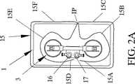
本発明の方法を実施するための上述した装置/ツール3の使用について、特に図2A−Cを用いて説明する。最初に、切断ワイヤー15を接着剤に沿って挿入する。接着剤は、通常、固定の乗り物用サイドウィンドウ1要素を概略的に示した受け入れ構造体2へ接合する。図1Cを参照された。切断ワイヤー15は、接着剤に沿って、一般に使用されるくぼんだ針(図示せず)により、ウィンドウ要素1の側面の端1Cと構造体2の間に挿入される。以下に明確にするように、ワイヤー15の長さは、ウィンドウ要素1のサイズに対応する。特に、挿入ポイントIPでは、ワイヤー15の両端15A及び15Dは、通常はウィンドウ1の外部側である第一の側1Aから挿入し、そのウィンドウ1の外部の内部側である他の側1Bへ通す。その結果、自由端15A、15Dは、乗り物の内部に配置される。ワイヤの端部15A、ワイヤ部分15B及びワイヤ端部15D、ワイヤ部分15Eは、内部で、ほぼ等しい長さである。ワイヤ部分15C、15Fは図2Aに示すように、ウィンドウ1の第一の側/外部1A上にある。ウィンドウ1の周囲の閉ループ中に配する。ユーザは、内部の両端を少し引いてもよい。図2Bで示すように、ワイヤー15はウィンドウ要素1の外部に端部1Cに配置する。 The use of the device /
装置/ツール3は、吸着盤7、8を真空にすることにより、ウィンドウ1の第二の側1Bに取り付けられる。ワイヤー15の第一の端部15A及び内側の部分15Bは隣接し、関連する溝14の中で吸着部材6のまわりでガイドされる。上述のように、ワイヤ端15Aは、ウィンチ機構16のローラー18のうちの一つに取り付けられる。第一のワイヤ端15Aは、特に、吸着部材6からもっとも離れているウィンチ機構ローラー18に取り付けられる。その理由は後述する。レンチ21の操作でウィンチ機構16を駆動し、ワイヤーを引き、その張力が増加する。またワイヤー15の内部の部分15Bと外部の部分15Cの間に鋭角αが形成される。このような鋭角部分は切断の有効性を改善する。ワイヤー15Aからワイヤー部分15Cまでの張力がさらに増加するため、ワイヤーは、鋭角部分でウィンドウ要素1と構造2の間の接着剤を切り離し始める。The device /
この初期動作、すなわち第一のワイヤー端部15Aからワイヤー部分15Cまでを緊張させることが切断動作に加えて重要な目的である。ワイヤ端部が挿入ポイントIPで交差しないことを確実にするために利用できるからである。ワイヤ端部が挿入ポイントIPで交差した場合、第一のワイヤ端部の張力が、ワイヤーが切断するとともに緩んでしまうからである。ワイヤー部分が交差していないことを確認したら、すぐに、ワイヤー15の第2の端部15Dを対応するウィンチ機構17に取り付ける。この段階では、第一のウィンチ機構16を動作させるか、それとも、二者択一で2つのウィンチ16、17を操作するかは選択できる。対応するワイヤー端部15Aからワイヤー部分15Cまで及び15Dからワイヤー部分15Fまでが会合点MP(図2C参照)に達すると、そこで2つのワイヤー端が構造2からのウィンドウ1を切断して緩む。 In addition to the cutting operation, this initial operation, that is, tensioning from the
第一のケースでは、ワイヤー端部15Aからワイヤー部分15Cまでは、第一のウィンチ機構16及び切断ポイントのローラー18上に巻かれる。そのとき、ワイヤー部分15Bと15Cの間の角度はαで、第2のウィンチ機構17の動作が始まるまで、挿入ポイントIPから会合点MPまで、移動する。この第一のケースでは、第二の緩んでいるワイヤー端部15Dを第一のウィンチ16の動作中に取り付ける必要はない。接着剤とワイヤー15の間の摩擦によってウィンドウ1の外部の端に沿ってワイヤー15が滑ること防がれるためである。ワイヤーが交差しないことを確認したらすぐに、ワイヤーの第二の端部15Dはウィンチ機構17に取り付けられる。そして、2つのウィンチ機構は、会合点MPで両方のワイヤー部分15A−C及び15D−Fが出会うまで、交互的に操作する。 In the first case, the
ワイヤ端15A、15Dを整えることによって、対応するガイド吸着部材5、6から離れている、それぞれのウィンチ機構のローラー18に取り付け、そして、ワイヤエンドはウィンチ在校のエリアで交差し、好的な鋭い削り角αが、両方のワイヤー部分15A−C、15D−Fのための十分な切断操作中に維持される。これは、ツール3の位置を調節せずにウィンドウ1の周囲で有効な切断が達成されることを意味する。 By arranging the wire ends 15A, 15D, they are attached to the
図示の実施例では、挿入ポイントIPは、ほぼウィンドウ要素1の一つの側の中間点にある。この位置は一つの正常な選択位置である。しかしながら、本発明は、挿入ポイントIPの位置をそのように選ぶことに制限されない。実際、最も適切な挿入ポイントIPは各適用及び/または/状況に応じて変わり、図2A−Cで見られるように、ウィンドウ要素1の上部かより低い側にあってもよい。挿入ポイントIPの様々な位置のうちでただ一つ効果的な位置は、ウィンチ機構16あるいは17のうちの1つが他のもの以上に操作されなければならないであろうということである。 In the illustrated embodiment, the insertion point IP is approximately at the midpoint on one side of the
本発明の方法は、乗り物に固定されたサイドウィンドウを安全かつ非破壊で除去を可能な点で独特である。さらに、本発明の方法は非常に有効で、実施が簡単であり、オペレーターが単一のツールを使用し、装置の位置を変えることも要求せずに、ウィンドウ要素を十分に緩く切断できる。
How the present inventionis unique in being fixed to the vehicle the side windows safe and possible points nondestructive removal. Furthermore, the method of the present invention is very effective and simple to implement, and the window elements can be cut sufficiently loosely without requiring the operator to use a single tool and reposition the device.
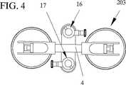
本発明は、現在最も実際的なものであると考えられる実施例、具体例に関して記述いる。したがって、本発明が図示された例に制限されないことは理解されよう。例えば、装置3は、2つのウィンチ16、17が、ハンドルとほぼ平行なラインに沿って並んでいる具体例として示した。これは、正常な用途には実際的なために尊重され、好まれる配置である。しかしながら、これはその他のウィンチの配置であって、特定の状況あるいは適用にふさわしいものを排除しない。そのような可能な修正済の配置例を図3、図4中に示す。図3は、2つのウィンチ16、17が、直角にハンドル4の中心線Cと交差するラインDに沿って並んで位置するツール103の実施例を示す。図4は、2つのウィンチ16、17がハンドル4の異なるサイドに置かれるツール203の実施例を示す。例えば、図3に示した具体例の変形としては、ハンドルの中心線に垂直でないラインに沿って2つのウィンチを並設するものが考えられる。
The present invention has been described with reference to examples and examples which are presently considered to be the most practical. Accordingly, it will be understood that the invention is not limited to the illustrated example. For example, the
この変形例の主な利点は、ハンドル、及びそのために全ツールの長さが縮小され得るということである。他方、そのような変形例は、ウィンドウの周囲を十分に切断するために装置の再ポジショニングを要求するかもしれない。 The main advantage of this variant is that the length of the handle and therefore the total tool can be reduced. On the other hand, such a variant may require repositioning of the device in order to sufficiently cut around the window.
したがって、本発明は、請求の範囲の記載の範囲内に含まれる様々な修正及び等価な例をも含む。 Accordingly, the present invention includes various modifications and equivalent examples included within the scope of the claims.
1 ウィンドウ要素
2 受け入れ構造体
3 ツール
5、6 吸着部材
4 ハンドル
4A、4B ハンドルの立面部
4A、4B ハンドルの端部
5A、6A 支持部
5C 穴
7、8 ゴム吸着盤部
9、10 ラッチ装置
11、12 金属ディスク
13、14 ガイド溝
15 切断ワイヤー
15A ワイヤの端部
15B ワイヤ部分
15D ワイヤ端部
15E ワイヤ部分
16、17 ウィンチ機構
18 ローラー
19 開口
20 解除ボタン
21 ハンドル
22 ソケット
25 ブラケット
30 ボルト
31 ナット
103 ツール
L1、L2 ツールの全長
IP 挿入ポイント
MP 会合点
DESCRIPTION OF
Claims (6)
Translated fromJapanese前記サイドウィンドウ要素(1)は、第一の側面(1A)及び他の側面である第2の側面(1B)を有し、かつ前記乗り物の受け枠(2)に前記サイドウィンドウ要素(1)の周囲全体の端部(1C)を接着剤で接合してあり、
前記サイドウィンドウ要素(1)の第一の側面(1A)から前記サイドウィンドウ要素(1)の第2の側面(1B)まで、前記サイドウィンドウ要素(1)の端部(1C)の周囲全体を接合している接着剤中を通してワイヤー(15)の第一と第二端(15A、15D)を挿入して前記ワイヤー(15)通し、そして、
該ワイヤー(15)の第一と第二端(15A、15D)を前記第2の側面(1B)の上に出して前記サイドウィンドウ要素(1)の前記周囲全体の端部(1C)に沿ってワイヤー(15)を輪形をなすように配し、
前記サイドウィンドウ要素(1)の前記第2の側面(1B)に固着した単一のツール(3)の第一のワイヤー巻き取り機構(16)に前記ワイヤーの第一の端(15A)を取り付け、前記第一のワイヤー巻き取り機構(16)で前記ワイヤー(15)の第一の端(15A)を引いて、ワイヤー(15)に張力を与え、
前記単一ツール(3)の他のワイヤー巻き取り機構(17)に前記ワイヤー(15)の第二の端(15D)を取り付け、そして
前記ワイヤー(15)の第一と第二の端(15A、15D)を引き、前記サイドウィンドウ要素(1)の端部(1C)の周囲全体のまわりの接着剤を該ワイヤー(15)で切断することを特徴とする乗り物に固定されたサイドウィンドウ要素を取り除く方法。A method of removing from a vehicle a side window element (1) fixed to the vehicle,
The side window element (1) has a first side surface (1A) and a second side surface (1B) which is another side surface, and the side window element (1) is mounted on a receiving frame (2) of the vehicle. The end part (1C) of the entire periphery of is joined with an adhesive,
The entire periphery of the end portion (1C) of the side window element (1) from the first side surface (1A) of the side window element (1) to the second side surface (1B) of the side window element (1). Insert the first and second ends (15A, 15D) of the wire (15) through the bonding adhesive and thread the wire (15); and
The first and second ends (15A, 15D) of the wire (15) are placed on the second side surface (1B) and along the end portion (1C) of the entire periphery of the side window element (1). And arrange the wire (15) in a ring shape,
Attaching the first end (15A) of the wire to the first wire winding mechanism (16) of a single tool (3) secured to the second side (1B) of the side window element (1) The first wire winding mechanism (16) pulls the first end (15A) of the wire (15) to give tension to the wire (15),
The second end (15D) of the wire (15) is attached to the other wire winding mechanism (17) of the single tool (3), and the first and second ends (15A) of the wire (15) , 15D) and cutting the adhesive around the entire periphery (1C) of the end portion of the side window element (1) with the wire (15). How to get rid of.
Applications Claiming Priority (1)
| Application Number | Priority Date | Filing Date | Title |
|---|---|---|---|
| PCT/SE2003/000818WO2004103747A1 (en) | 2003-05-21 | 2003-05-21 | A method and a device for removing vehicle windows |
Publications (2)
| Publication Number | Publication Date |
|---|---|
| JP2006526136A JP2006526136A (en) | 2006-11-16 |
| JP4614067B2true JP4614067B2 (en) | 2011-01-19 |
Family
ID=33476138
Family Applications (1)
| Application Number | Title | Priority Date | Filing Date |
|---|---|---|---|
| JP2004572170AExpired - Fee RelatedJP4614067B2 (en) | 2003-05-21 | 2003-05-21 | How to delete a vehicle window |
Country Status (9)
| Country | Link |
|---|---|
| US (2) | US7618023B2 (en) |
| EP (2) | EP1628846B1 (en) |
| JP (1) | JP4614067B2 (en) |
| AT (1) | ATE465038T1 (en) |
| AU (1) | AU2003243068A1 (en) |
| CA (2) | CA2525152C (en) |
| DE (1) | DE60332286D1 (en) |
| ES (1) | ES2344787T3 (en) |
| WO (2) | WO2004103747A1 (en) |
Families Citing this family (41)
| Publication number | Priority date | Publication date | Assignee | Title |
|---|---|---|---|---|
| JP4614067B2 (en)* | 2003-05-21 | 2011-01-19 | ラムフセット・ダラ−シュペグラー・アクティエボラーグ | How to delete a vehicle window |
| GB0420468D0 (en)* | 2004-09-14 | 2004-10-20 | Carglass Luxembourg Sarl Zug | Vehicle glazing panel cut out |
| US20080012349A1 (en)* | 2005-09-14 | 2008-01-17 | William Finck | Vehicle Glazing Panel Cut Out |
| GB2430909A (en)* | 2005-10-04 | 2007-04-11 | Carglass Luxembourg Sarl Zug | Tool for handling glazing panels |
| DE102006013417A1 (en) | 2006-03-14 | 2007-09-20 | C. & E. Fein Gmbh | Device and method for severing the adhesive bead of a vehicle window |
| DE102006048518B4 (en)* | 2006-10-13 | 2009-07-30 | Airbus Deutschland Gmbh | Device for largely residue-free removal of glued window frames |
| US20090283214A1 (en)* | 2008-05-16 | 2009-11-19 | Jack Richard Nelson | Device and method for separating adhesive |
| EP2191943B1 (en)* | 2008-12-01 | 2013-01-16 | C. & E. Fein GmbH | Device and method for separating the adhesive beaded rim of adhered windows |
| DE102008060803A1 (en) | 2008-12-01 | 2010-06-02 | C. & E. Fein Gmbh | Coil for a winding device |
| DE102008060802A1 (en)* | 2008-12-01 | 2010-06-02 | C. & E. Fein Gmbh | Device for severing the adhesive bead of glued-in panes |
| DE102008060812A1 (en)* | 2008-12-01 | 2010-06-02 | C. & E. Fein Gmbh | Device for severing adhesive bulge of disk, has motor-driven winding unit and coil for winding cutting unit for severing adhesive bulge, where winding unit is detachably held by coupling on suction plate fixed at disk inner surface |
| DE102008060811A1 (en)* | 2008-12-01 | 2010-06-02 | C. & E. Fein Gmbh | Device for severing adhesive bulge of disk, has motor-driven winding unit and coil for winding cutting unit for severing adhesive bulge, where winding unit is detachably held by coupling on suction plate fixed at disk inner surface |
| DE102008060804A1 (en)* | 2008-12-01 | 2010-06-02 | C. & E. Fein Gmbh | Device for cutting-through adhesive bead of adhesive disk, has cutting unit, winding unit for winding up cutting unit, where exchangeable support is provided for supporting winding unit at vehicle, particularly at disk frame |
| GB2465847B (en)* | 2008-12-08 | 2013-01-16 | Belron Hungary Kft Zug Branch | Vehicle glazing panel cut out |
| WO2011030480A1 (en)* | 2009-09-14 | 2011-03-17 | シャープ株式会社 | Apparatus and method for peeling adhesive film |
| US8572835B2 (en)* | 2009-10-29 | 2013-11-05 | Dell Skluzak | Automotive glass-setting tool |
| GB2477955B (en) | 2010-02-19 | 2015-01-28 | Belron Hungary Kft Zug Branch | Wire handling for vehicle glazing panel cut out |
| GB201018558D0 (en)* | 2010-11-03 | 2010-12-15 | Belron Hungary Kft Zug Branch | Windscreen installation apparatus and method |
| GB2540053B (en) | 2010-11-22 | 2017-06-07 | Belron Hungary Kft - Zug Branch | Apparatus and method for cutting out a vehicle glazing panel |
| FR2968264B1 (en)* | 2010-12-03 | 2013-03-01 | Gillet Group | DEVICE FOR SECURING CUT |
| KR101235705B1 (en)* | 2010-12-09 | 2013-02-21 | 심명섭 | front window separation apparatus for vehicle |
| PH12013501345A1 (en)* | 2010-12-23 | 2022-10-24 | Purdue Pharma Lp | Tamper resistant solid oral dosage forms |
| DE102011013790B4 (en)* | 2011-03-03 | 2018-03-29 | C. & E. Fein Gmbh | Apparatus and method for severing the adhesive bead of glued-in panes |
| WO2012121631A1 (en)* | 2011-03-04 | 2012-09-13 | Ramhuset Patent Ab | Winch friction brake, method and winch tool |
| DE102011013890A1 (en)* | 2011-03-07 | 2012-09-13 | C. & E. Fein Gmbh | Apparatus and method for severing the adhesive bead of glued-in panes |
| GB2489835B (en)* | 2011-05-19 | 2016-09-28 | Terry Vaughan Richard | Cutting device |
| EP2540463B8 (en)* | 2011-06-27 | 2015-02-25 | Iosif Robert Horvath | Device and method for separating the adhesive beaded rim of fixed windows |
| US20140137416A1 (en)* | 2012-11-22 | 2014-05-22 | Horvath Iosif Robert | Cutting Blade Cutting Device |
| SI3046737T1 (en)* | 2013-09-20 | 2020-07-31 | Belron International Limited, | Vehicle glazing panel cut out |
| ITAN20130211A1 (en)* | 2013-11-15 | 2015-05-16 | Pietro Ubaldo Antonio Allegra | MANUAL DEVICE FOR THE REMOVAL OF MOTOR VEHICLE GLASSES |
| DE202013105337U1 (en) | 2013-11-22 | 2013-12-04 | Ktl International Co., Ltd. | Dismantling device for vehicle glass |
| GB2526308B (en) | 2014-05-20 | 2021-06-09 | Belron Int Ltd | Glazing panel removal |
| GB201418184D0 (en) | 2014-10-14 | 2014-11-26 | Belron Hungary Kft Zug Branch | Apparatus and method for cutting out a vehicle glazing panel |
| SE538489C2 (en)* | 2014-12-02 | 2016-08-02 | Ramhuset Patent Ab | Method and device for removing vehicle windshields |
| US10227965B2 (en)* | 2015-03-23 | 2019-03-12 | Kent R. Mayhugh | Windshield removal assist device |
| KR101720564B1 (en)* | 2016-11-07 | 2017-03-29 | 권용진 | Removal device for Automotive glass |
| CZ2017232A3 (en)* | 2017-04-27 | 2018-04-18 | VladimĂr Hauser | A device for releasing glass from vehicle bodies and a method of releasing glass from vehicle bodies |
| CN107640669B (en)* | 2017-09-06 | 2019-06-21 | 中国电子科技集团公司第三十八研究所 | A cable retracting device with adjustable wrap angle |
| TWD212442S (en)* | 2020-04-08 | 2021-07-01 | 德商博勒股份公司 | Suction lifter |
| US12214516B2 (en) | 2021-03-03 | 2025-02-04 | Equalizer Industries, Inc. | Line-type auto glass removal tools for use with an independent vacuum cup device |
| US20230234428A1 (en)* | 2022-01-27 | 2023-07-27 | Mcs Industries, Inc. | Support apparatus for a golf cart windshield, golf cart utilizing the same and related methods |
Family Cites Families (26)
| Publication number | Priority date | Publication date | Assignee | Title |
|---|---|---|---|---|
| US2305995A (en)* | 1940-10-17 | 1942-12-22 | William F Roberts | Auto glass removing and replacement tool |
| US3711677A (en)* | 1970-03-11 | 1973-01-16 | Rubie Nell Little Howell | Automobile windshield and backglass removal tool |
| US3765550A (en)* | 1971-08-05 | 1973-10-16 | Ace Glass Co | Dolly for lifting and transporting and installing large sheets of flat glass and other flat sheet products |
| US3770259A (en)* | 1972-10-20 | 1973-11-06 | M Wagreich | Vacuumatic clamp |
| US4457503A (en)* | 1982-03-10 | 1984-07-03 | Connor Donald R | Suction clamp |
| DE3215892A1 (en) | 1982-04-29 | 1983-11-10 | Audi Nsu Auto Union Ag, 7107 Neckarsulm | DEVICE FOR CUTTING OUT GLUED WINDOWS |
| SE8502633D0 (en) | 1985-05-31 | 1985-05-29 | Folksam Auto Ab | REMOVAL SET AND DEVICE |
| DE4012207C1 (en) | 1990-04-14 | 1991-10-24 | Gurit-Essex Ag, Freienbach, Ch | |
| EP0437793A3 (en) | 1990-01-15 | 1991-12-18 | Gurit-Essex Ag | Cutting string |
| US4995153A (en)* | 1990-03-09 | 1991-02-26 | Equalizer Tools, Inc. | Glass cut-out wire gripper apparatus and method |
| JPH081598A (en) | 1994-06-24 | 1996-01-09 | Koizumi:Kk | Method and device for removing window glass |
| US5622093A (en)* | 1995-01-19 | 1997-04-22 | Equalizer Industries, Inc. | Automobile windshield removal apparatus and method |
| WO1998058779A1 (en)* | 1997-06-20 | 1998-12-30 | Naessl Walter | Process and device for detaching an element glued to a part |
| DE29711291U1 (en) | 1997-06-28 | 1997-09-04 | Eduard Wille Gmbh & Co, 42349 Wuppertal | Disc cutting device |
| US6101702A (en)* | 1998-02-19 | 2000-08-15 | Claycomb; Kevin | Windshield lift and method of use |
| US6338619B1 (en)* | 1998-09-15 | 2002-01-15 | Auto Glass Specialists, Inc. | Fixture for window repair |
| DE29819258U1 (en)* | 1998-10-28 | 1999-04-15 | Gmeilbauer, Engelbert, 82229 Seefeld | Tool for cutting out car windscreens |
| JP4221126B2 (en) | 1999-10-14 | 2009-02-12 | ビューテック株式会社 | Mall mounting method, mall mounting apparatus, and glass plate with mall |
| US6616800B2 (en) | 2001-03-05 | 2003-09-09 | Rolf O. Eriksson | Method and device for removing windshields |
| JP2003145486A (en)* | 2001-11-19 | 2003-05-20 | Asahi Glass Co Ltd | How to remove vehicle window material |
| US6778086B2 (en)* | 2002-05-02 | 2004-08-17 | Gerald Angelo Morrone | Open window security lock |
| US7823845B2 (en)* | 2002-05-09 | 2010-11-02 | Dmr Holding Group, Llc | Corner climber |
| JP4614067B2 (en)* | 2003-05-21 | 2011-01-19 | ラムフセット・ダラ−シュペグラー・アクティエボラーグ | How to delete a vehicle window |
| JP2007160431A (en)* | 2005-12-12 | 2007-06-28 | Takatori Corp | Cutting method using wire saw and cut work receiving member of wire saw |
| DE102006013417A1 (en)* | 2006-03-14 | 2007-09-20 | C. & E. Fein Gmbh | Device and method for severing the adhesive bead of a vehicle window |
| US7270357B1 (en)* | 2006-03-16 | 2007-09-18 | Lih Yann Industrial Co., Ltd. | Distance and orientation adjustable suction device |
- 2003
- 2003-05-21JPJP2004572170Apatent/JP4614067B2/ennot_activeExpired - Fee Related
- 2003-05-21USUS10/556,500patent/US7618023B2/ennot_activeExpired - Fee Related
- 2003-05-21ESES03817023Tpatent/ES2344787T3/ennot_activeExpired - Lifetime
- 2003-05-21CACA 2525152patent/CA2525152C/ennot_activeExpired - Fee Related
- 2003-05-21DEDE60332286Tpatent/DE60332286D1/ennot_activeExpired - Lifetime
- 2003-05-21EPEP20030817023patent/EP1628846B1/ennot_activeExpired - Lifetime
- 2003-05-21ATAT03817023Tpatent/ATE465038T1/ennot_activeIP Right Cessation
- 2003-05-21WOPCT/SE2003/000818patent/WO2004103747A1/enactiveApplication Filing
- 2003-05-21AUAU2003243068Apatent/AU2003243068A1/ennot_activeAbandoned
- 2004
- 2004-05-21EPEP20040734461patent/EP1628847A1/ennot_activeWithdrawn
- 2004-05-21USUS10/555,691patent/US20070000361A1/ennot_activeAbandoned
- 2004-05-21WOPCT/SE2004/000800patent/WO2004103748A1/enactiveApplication Filing
- 2004-05-21CACA 2525154patent/CA2525154A1/ennot_activeAbandoned
Also Published As
| Publication number | Publication date |
|---|---|
| US7618023B2 (en) | 2009-11-17 |
| ATE465038T1 (en) | 2010-05-15 |
| AU2003243068A1 (en) | 2004-12-13 |
| US20070040415A1 (en) | 2007-02-22 |
| DE60332286D1 (en) | 2010-06-02 |
| JP2006526136A (en) | 2006-11-16 |
| WO2004103747A1 (en) | 2004-12-02 |
| CA2525154A1 (en) | 2004-12-02 |
| WO2004103748A1 (en) | 2004-12-02 |
| CA2525152A1 (en) | 2004-12-02 |
| EP1628847A1 (en) | 2006-03-01 |
| EP1628846B1 (en) | 2010-04-21 |
| ES2344787T3 (en) | 2010-09-07 |
| CA2525152C (en) | 2011-03-15 |
| US20070000361A1 (en) | 2007-01-04 |
| EP1628846A1 (en) | 2006-03-01 |
Similar Documents
| Publication | Publication Date | Title |
|---|---|---|
| JP4614067B2 (en) | How to delete a vehicle window | |
| JP6018577B2 (en) | Apparatus and method for cutting a glazing panel for a vehicle | |
| US6616800B2 (en) | Method and device for removing windshields | |
| ES2539658T3 (en) | Apparatus and technique for cutting glass panels of vehicles | |
| CN107002423B (en) | Lifting mechanism, lifting equipment, lifting method using this equipment | |
| JP2016508073A (en) | Glass panel removal apparatus and method | |
| EP2540463B1 (en) | Device and method for separating the adhesive beaded rim of fixed windows | |
| JP6427170B2 (en) | Vehicle glazing panel cutting method | |
| US20200086518A1 (en) | Windshied removal tool | |
| GB2511108A (en) | Device for removing a window from a frame of a vehicle | |
| JP4532400B2 (en) | Hard snow ring removal device and hard snow ring removal method | |
| EP3708315B1 (en) | Car windshield removal apparatus and method | |
| CN107411829B (en) | Crown extractor | |
| JP2007247216A (en) | Winding spring adjusting device for mesh or planar screen | |
| JP2007247216A5 (en) | ||
| BE1015994A5 (en) | Winder strap. | |
| JP4179791B2 (en) | Resin pipe cutoff tool | |
| IE20120374A1 (en) | Device for removing a window from a frame of a vehicle | |
| KR101071765B1 (en) | Wire harness hand winder | |
| US20140137416A1 (en) | Cutting Blade Cutting Device | |
| JP2002264645A (en) | Method for removing window pane of automobile | |
| JPH10129942A (en) | Vehicle code collection device | |
| JPH07156700A (en) | Pulling device for trolley wire connection | |
| JP2007224681A (en) | Device for mounting/dismounting winding shaft for net or plane screen | |
| JP2006094695A (en) | Hard snow ring removal device and hard snow ring removal method |
Legal Events
| Date | Code | Title | Description |
|---|---|---|---|
| A621 | Written request for application examination | Free format text:JAPANESE INTERMEDIATE CODE: A621 Effective date:20060605 | |
| A621 | Written request for application examination | Free format text:JAPANESE INTERMEDIATE CODE: A621 Effective date:20060517 | |
| A131 | Notification of reasons for refusal | Free format text:JAPANESE INTERMEDIATE CODE: A131 Effective date:20090213 | |
| A601 | Written request for extension of time | Free format text:JAPANESE INTERMEDIATE CODE: A601 Effective date:20090512 | |
| A602 | Written permission of extension of time | Free format text:JAPANESE INTERMEDIATE CODE: A602 Effective date:20090519 | |
| A521 | Request for written amendment filed | Free format text:JAPANESE INTERMEDIATE CODE: A523 Effective date:20090612 | |
| A02 | Decision of refusal | Free format text:JAPANESE INTERMEDIATE CODE: A02 Effective date:20091210 | |
| A521 | Request for written amendment filed | Free format text:JAPANESE INTERMEDIATE CODE: A523 Effective date:20100405 | |
| A521 | Request for written amendment filed | Free format text:JAPANESE INTERMEDIATE CODE: A523 Effective date:20100511 | |
| A911 | Transfer to examiner for re-examination before appeal (zenchi) | Free format text:JAPANESE INTERMEDIATE CODE: A911 Effective date:20100618 | |
| TRDD | Decision of grant or rejection written | ||
| A01 | Written decision to grant a patent or to grant a registration (utility model) | Free format text:JAPANESE INTERMEDIATE CODE: A01 Effective date:20100921 | |
| A01 | Written decision to grant a patent or to grant a registration (utility model) | Free format text:JAPANESE INTERMEDIATE CODE: A01 | |
| A61 | First payment of annual fees (during grant procedure) | Free format text:JAPANESE INTERMEDIATE CODE: A61 Effective date:20101005 | |
| R150 | Certificate of patent or registration of utility model | Ref document number:4614067 Country of ref document:JP Free format text:JAPANESE INTERMEDIATE CODE: R150 Free format text:JAPANESE INTERMEDIATE CODE: R150 | |
| FPAY | Renewal fee payment (event date is renewal date of database) | Free format text:PAYMENT UNTIL: 20131029 Year of fee payment:3 | |
| A711 | Notification of change in applicant | Free format text:JAPANESE INTERMEDIATE CODE: A711 Effective date:20101117 | |
| FPAY | Renewal fee payment (event date is renewal date of database) | Free format text:PAYMENT UNTIL: 20131029 Year of fee payment:3 | |
| S111 | Request for change of ownership or part of ownership | Free format text:JAPANESE INTERMEDIATE CODE: R313113 | |
| FPAY | Renewal fee payment (event date is renewal date of database) | Free format text:PAYMENT UNTIL: 20131029 Year of fee payment:3 | |
| R350 | Written notification of registration of transfer | Free format text:JAPANESE INTERMEDIATE CODE: R350 | |
| R250 | Receipt of annual fees | Free format text:JAPANESE INTERMEDIATE CODE: R250 | |
| R250 | Receipt of annual fees | Free format text:JAPANESE INTERMEDIATE CODE: R250 | |
| R250 | Receipt of annual fees | Free format text:JAPANESE INTERMEDIATE CODE: R250 | |
| R250 | Receipt of annual fees | Free format text:JAPANESE INTERMEDIATE CODE: R250 | |
| R250 | Receipt of annual fees | Free format text:JAPANESE INTERMEDIATE CODE: R250 | |
| R250 | Receipt of annual fees | Free format text:JAPANESE INTERMEDIATE CODE: R250 | |
| R250 | Receipt of annual fees | Free format text:JAPANESE INTERMEDIATE CODE: R250 | |
| LAPS | Cancellation because of no payment of annual fees |