JP4613455B2 - Vehicle cooling system - Google Patents
Vehicle cooling systemDownload PDFInfo
- Publication number
- JP4613455B2 JP4613455B2JP2001206890AJP2001206890AJP4613455B2JP 4613455 B2JP4613455 B2JP 4613455B2JP 2001206890 AJP2001206890 AJP 2001206890AJP 2001206890 AJP2001206890 AJP 2001206890AJP 4613455 B2JP4613455 B2JP 4613455B2
- Authority
- JP
- Japan
- Prior art keywords
- engine
- motor
- control device
- compressor
- stopped
- Prior art date
- Legal status (The legal status is an assumption and is not a legal conclusion. Google has not performed a legal analysis and makes no representation as to the accuracy of the status listed.)
- Expired - Fee Related
Links
Images


Classifications
- F—MECHANICAL ENGINEERING; LIGHTING; HEATING; WEAPONS; BLASTING
- F25—REFRIGERATION OR COOLING; COMBINED HEATING AND REFRIGERATION SYSTEMS; HEAT PUMP SYSTEMS; MANUFACTURE OR STORAGE OF ICE; LIQUEFACTION SOLIDIFICATION OF GASES
- F25B—REFRIGERATION MACHINES, PLANTS OR SYSTEMS; COMBINED HEATING AND REFRIGERATION SYSTEMS; HEAT PUMP SYSTEMS
- F25B2400/00—General features or devices for refrigeration machines, plants or systems, combined heating and refrigeration systems or heat-pump systems, i.e. not limited to a particular subgroup of F25B
- F25B2400/07—Details of compressors or related parts
- F25B2400/075—Details of compressors or related parts with parallel compressors
Landscapes
- Air-Conditioning For Vehicles (AREA)
Description
Translated fromJapanese【0001】
【発明の属する技術分野】
本発明は、走行中に一時停車した時に、エンジンを停止させる所謂アイドルストップ車両における車両用冷房装置に関するものである。
【0002】
【従来の技術】
従来の車両用冷房装置は、特開2000−80348号公報に示されるように、装置内にエンジンおよびモータを駆動源とする圧縮機を有し、エンジン停止時にはモータを駆動源として圧縮機を駆動させるものにおいて、モータの負荷を低減する手段を設けたものが知られている。具体的には、モータ作動時にエアミックスドアをフルクール位置に固定したり、内気循環モード側に固定したり、蒸発器凍結防止温度を所定値だけ上昇させたりするように制御するものとしている。
【0003】
これにより、エンジンによって駆動されていた時に必要とされていた圧縮仕事を減らして、圧縮機の消費動力を低減し、モータにかかる負荷を低減させている。そして、バッテリ電源の異常な消費を防止するようにしている。
【0004】
【発明が解決しようとする課題】
しかしながら、上記技術によって定常的な使用条件での圧縮機の消費動力を低減することができるものの、乗員による冷房の使用条件や走行時のエンジン停止頻度等には、当然バラツキが有り、冷房負荷条件が高い場合やエンジン停止時間が長い場合のような非定常的な条件においても、それに合せて圧縮機を作動させれば、バッテリ電源のチャージ容量を確保することができなくなる。即ち、バッテリ上りとなる。
【0005】
本発明の目的は、上記問題に鑑み、走行中に繰返されるエンジン停止において、各停止時には平均的な冷房性能を確保して、モータの過度な作動によるバッテリ上りを確実に防止する車両用冷房装置を提供することにある。
【0006】
【課題を解決するための手段】
本発明は上記目的を達成するために、以下の技術的手段を採用する。
【0007】
請求項1に記載の発明では、走行中に一時停車した時に、エンジン(10)が停止される車両に適用されるものであって、エンジン(10)およびバッテリ(140)を電源とするモータ(121)の駆動力を受けて作動する圧縮機(111、122)を含む冷凍サイクル装置(110)と、モータ(121)の作動を制御する制御装置(130)とが設けられ、冷凍サイクル装置(110)作動時に、エンジン(10)が停止した場合、圧縮機(122)を駆動させるために、制御装置(130)によってモータ(121)が作動される車両用冷房装置において、制御装置(130)は、1回の停車中におけるモータ(121)の累積作動時間が第1所定時間(t1)以内となるように作動させ、
第1所定時間(t1)は、外気温度あるいは冷凍サイクル装置(110)の冷房負荷が低いほど、短くなるように設定されることを特徴としている。
【0008】
これにより、第1所定時間(t1)以上モータ(121)が作動されることがないので、バッテリ上りを確実に防止することができる。
【0009】
ここで、第1所定時間(t1)を、例えば、車両走行条件からシュミレートした時のアイドリングの頻度と、バッテリ(140)の使用回数から求められる放電深度(使用時間)とから決定するようにしてやれば、各停車時の冷房性能を平均的に確保しつつ、上記バッテリ上りを確実に防止することができるようになる。
【0010】
そして、第1所定時間(t1)は、外気温度あるいは冷凍サイクル装置(110)の冷房負荷が低いほど、短くなるように設定してやれば、外気温度や冷房負荷に応じてモータ(121)を作動させてやれば良くなるので、不要な電力の消費を抑制し、モータ(121)の消費電力を更に低減することができる。
【0011】
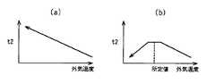
更に、請求項2に記載の発明のように、第1所定時間(t1)は、外気温度あるいは冷房負荷が所定値を越えて更に低くなると、逆に長くなるように設定してやれば、冬場における車両窓ガラスへの防曇性を向上させることができる。
【0012】
請求項3に記載の発明では、制御装置(130)は、エンジン(10)の作動を制御するエンジン制御装置(11)に対して、エンジン(10)の始動を要求するエンジン始動要求機能を有しており、制御装置(130)によって、モータ(121)が作動され、バッテリ(140)のバッテリ容量(C)が、所定容量(C1)を下回った時に、制御装置(130)は、モータ(121)の累積作動時間が第1所定時間(t1)以内であっても、その時点でモータ(121)を停止させると共に、エンジン始動要求機能によって、エンジン(10)を始動させるようにしたことを特徴としている。
【0013】
これにより、エンジン(10)を駆動源として圧縮機(111)が駆動されるので、冷房性能を確保しつつ、バッテリ上りを確実に防止できる。尚、エンジン10始動後は、バッテリ140の充電がなされる。
【0014】
請求項4に記載の発明では、モータ(121)の累積作動時間が第1所定時間(t1)を経過し、制御装置(130)によってモータ(121)が停止された後もエンジン(10)が停止状態にあり、所定部位(114)における冷房温度が第1所定温度(T1)を上回った時に、制御装置(130)は、エンジン始動要求機能によって、エンジン(10)を始動させるようにしたことを特徴としている。
【0015】
これにより、エンジン(10)停止時間が第1所定時間(t1)に対して長い場合でも、第1所定時間(t1)でモータ(121)を停止させバッテリ上りを防止し、且つ、エンジン(10)を駆動源として圧縮機(111)を作動させることで、冷房性能を確保することができる。
【0016】
請求項5に記載の発明では、制御装置(130)は、1回の停車中におけるモータ(121)の累積作動時間が第1所定時間(t1)以内となるように作動させ、
制御装置(130)によってモータ(121)が作動されており、所定部位(114)における冷房温度が、第2所定温度(T2)を下回った時に、制御装置(130)は、モータ(121)の累積作動時間が第1所定時間(t1)以内であっても、その時点でモータ(121)を停止するようにしたことを特徴としている。
【0017】
これにより、冷房温度が早い時点で充分に低下するならば、それに応じてモータ(121)の作動を停止するので、更にバッテリ(140)の消費電力を低減することができる。
【0018】
請求項6に記載の発明では、制御装置(130)は、エンジン(10)が停止してから、第2所定時間(t2)経過した後にモータ(121)を作動させるようにし、
制御装置(130)は、1回の停車中におけるモータ(121)の累積作動時間が第1所定時間(t1)以内となるように作動させることを特徴としている。
【0019】
これにより、エンジン(10)作動時に得られていた吐出圧力(P)が第2所定時間(t2)の間に順次低下することになる。この低下した吐出圧力(Pd)で、圧縮機(122)のモータ(121)を起動させてやれば良いので、エンジン(10)作動時の吐出圧力(P)で起動するのに比べて圧縮機(122)の消費動力を低減させることができ、モータ(121)の消費電力を低減できる。これに合せて、モータ(121)の起動時の突入電流値を低減させることができるので、突入電流による関連部品の寿命低下防止や、バッテリ(140)の電圧降下抑制による補機類の誤作動防止を図ることができる。
【0020】
ここで、請求項7に記載の発明のように、第2所定時間(t2)は、外気温度あるいは冷凍サイクル装置(110)の冷房負荷が低いほど、長くなるように設定してやれば、外気温度や冷房負荷に応じてモータ(121)を作動させてやれば良くなるので、不要な電力の消費を抑制し、モータ(121)の消費電力、突入電流を更に低減することができる。
【0021】
また、請求項8に記載の発明のように、第2所定時間(t2)は、外気温度あるいは冷房負荷が所定値を越えて更に低くなると、逆に短くなるように設定してやれば、請求項2に記載の発明と同様に、冬場における車両窓ガラスへの防雲性を向上させることができる。
【0022】
請求項9に記載の発明では、エンジン(10)が停止してから所定部位(114)における冷房温度が第3所定温度(T3)を上回るまでの温度上昇時間が、第2所定時間(t2)よりも長い場合、制御装置(130)は、第2所定時間(t2)に対して温度上昇時間を優先して、モータ(121)を作動させるようにしたことを特徴としている。
【0023】
これにより、第3所定温度(T3)までの冷房性能を確保しつつ、第2所定時間(t2)よりも長い時間分、モータ(121)の作動を行なわないようにできるので、更に消費電力の節約ができる。
【0024】
また、モータ(121)を作動させるタイミングを第3所定温度(T3)を基に決定できるので、第2所定時間(t2)を設定するよりも容易に対応できる。
【0025】
請求項10に記載の発明では、制御装置(130)は、1回の停車中におけるモータ(121)の累積作動時間が第1所定時間(t1)以内となるように作動させ、
エンジン(10)が停止状態から始動する際に、モータ(121)が第1所定時間(t1)の範囲内で作動している場合、制御装置(130)は、モータ(121)を停止させると共に、エンジン始動要求機能によって、その時点から第3所定時間(t3)経過の後にエンジン(10)を始動させるようにしたことを特徴としている。
【0026】
これにより、エンジン(10)を始動するためのスタータとモータ(121)とが同時に作動することがなく、バッテリ(140)の電圧降下を低減でき、補機類の誤作動を防止することができる。
【0027】
ここで、請求項11に記載の発明のように、第3所定時間(t3)は、0.5秒以下とするのが好ましい。
【0028】
これにより、エンジン(10)始動までの時間を不要に延ばすことなく、また乗員に対しても停車から発進に至るスムースな運転を可能とすることができる。
【0029】
請求項12に記載の発明では、エンジン(10)作動中の圧縮機(111)による吐出圧力(P)が、エンジン(10)停止後に、第1所定圧力(P1)を下回った時に、制御装置(130)は、モータ(121)を作動させるようにし、
制御装置(130)は、1回の停車中におけるモータ(121)の累積作動時間が第1所定時間(t1)以内となるように作動させることを特徴としている。
【0030】
請求項13に記載の発明では、制御装置(130)は、圧縮機(111)がエンジン(10)によって駆動される場合の吐出圧力(P)を可変する制御機能を有しており、エンジン(10)停止前に、エンジン(10)によって駆動される圧縮機(111)の吐出圧力(P)が、制御装置(130)によって低下する側に制御されている場合、制御装置(130)は、エンジン(10)が停止された時点でモータ(121)を作動させるようにし、
制御装置(130)は、1回の停車中におけるモータ(121)の累積作動時間が第1所定時間(t1)以内となるように作動させることを特徴としている。
【0031】
請求項14に記載の発明では、制御装置(130)は、圧縮機(111)がエンジン(10)によって駆動される場合の吐出圧力(P)を可変する制御機能を有しており、車両が減速状態にあり、停車するまでの間に、制御装置(130)は、エンジン(10)によって駆動される圧縮機(111)の吐出圧力(P)をそれ以前の値より低下させると共に、エンジン(10)が停止された後にモータ(121)を作動させるようにしたことを特徴としている。
【0032】
尚、請求項15、請求項16に記載の発明のように、圧縮機(111)の吐出量を低下させたり、冷凍サイクル装置(110)内に設けられる凝縮器(112)に空気を送風する送風機(112a)の送風量を増加させることで、吐出圧力(P)を低下させるようにするのが良い。
【0033】
請求項12〜請求項16に記載の発明によれば、モータ(121)を作動させる前に吐出圧力(P)を低下させることで、請求項6に記載の発明と同様の効果を得ることができる。
【0037】
上記請求項1〜請求項16に記載の発明には、請求項17に記載の発明のように、圧縮機(111)は、第1圧縮機(111)と第2圧縮機(122)とから成り、第1圧縮機(111)は、エンジン(10)を駆動源として作動するものとし、第2圧縮機(122)は、モータ(121)を駆動源として作動するものとし、第1圧縮機(111)および第2圧縮機(121)は、冷凍サイクル装置(110)内に並列に接続されるようにして用いるのが好適である。
【0038】
更に、請求項18に記載の発明のように、圧縮機(111)は、エンジン(10)およびモータ(121)を選択的に駆動源として作動するハイブリッドコンプレッサ(111a)としても良い。
【0039】
尚、上記各手段の括弧内の符号は、後述する実施形態記載の具体的手段との対応関係を示すものである。
【0040】
【発明の実施の形態】
(第1実施形態)
本発明の第1実施形態を図1〜図5に示し、まず、具体的な構成について図1を用いて説明する。
【0041】
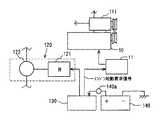
車両用冷房装置100は、走行中一時停車した時にエンジン10が停止される所謂アイドルストップ車両に適用されるものとしており、冷凍サイクル装置110、制御装置130およびバッテリ140とから成る。
【0042】
冷凍サイクル装置110は、周知の冷凍サイクルを形成するものであり、ここでは2つの圧縮機111、122を配設するものとしている。まず、冷凍サイクル内の冷媒を高温高圧に圧縮する第1圧縮機(以下、圧縮機)111、圧縮された冷媒を液化凝縮する凝縮器112、液化された冷媒を断熱膨張させる膨張弁113、膨張した冷媒を蒸発させ、その蒸発潜熱により自身を通過する空気を冷却する蒸発器114が冷媒配管115によって順次接続されている。尚、圧縮機111は、車両走行用のエンジン10を駆動源としてプーリーおよびプーリーベルトを介して作動するようにしている。
【0043】
凝縮器112には、この凝縮器112に空気を送風して冷媒の液化凝縮を促進させるための送風機112aが設けられている。
【0044】
同様に、蒸発器114には、送風機114bが設けられ、送風空気を冷媒との熱交換により冷却し、車室内に送風するようにしている。また、この蒸発器114の空気流れ下流側には、冷却された空気温度(蒸発器後方空気温度)を検出するための蒸発器温度センサ114aが設けられている。
【0045】
そして、第2圧縮機122が、上記圧縮機111に対して並列になるように、具体的には、凝縮器112の流入側と蒸発器114の流出側の間に配設されており、冷媒配管123によって接続されている。この第2圧縮機122は、バッテリ140を電源として作動されるモータ121を駆動源として駆動するものとしており、このモータ121と共に電動圧縮機120を構成している。この第2圧縮機122は、エンジン10が停止され上記圧縮機111が停止された時に駆動されるものである。
【0046】
尚、バッテリ140から後述する制御装置120に接続されるリード線部には、モータ121作動時における電流値を検出する電流センサ140aが設けられている。また、これら両圧縮機111、122の吐出側には、吐出圧力Pを検出する圧力センサ116が設けられている。
【0047】
次に、本発明の要部となる制御装置130の構成について説明する。
【0048】
制御装置130は、上記電動圧縮機120の作動を制御するものである。上記の蒸発器温度センサ114a、圧力センサ116、電流センサ140aからの検出信号が入力され、また、図示しない各種センサからの信号、即ち、車速、エンジン回転数、アイドルストップ判定、内気温度、外気温度、A/C要求信号等が入力されるようにしている。そして、これらの信号に基づいて、モータ121を駆動させ、第2圧縮機122を作動させるようにしている。(詳細後述)
また、この制御装置130は、当然のことながら、冷凍サイクル装置110の通常の運転のために、上記各信号に基づいて圧縮機111のON−OFF制御、送風機112a、114bのON−OFFおよび送風量の可変制御を行なうようにしている。
【0049】
本実施形態では、モータ121を消費電力の面で効果的に作動させ、且つ、モータ121の作動に伴なうバッテリ上りを確実に防止するための制御プログラムを予めメモリするようにしている。
【0050】
まず、車両が停車して、エンジン10が停止(アイドルストップ)されている間に、モータ121を作動させる累積作動時間を第1所定時間t1として定めている。この第1所定時間t1の設定に当たっては、例えば、車両走行条件からシュミレートした時のアイドリングの頻度と、バッテリ140の使用回数から求められる放電深度(使用時間)とから定めるようにしている。即ち、繰返される各アイドリング時間には当然、長短のバラツキが考えられるが、ここでは、バッテリ寿命時間を考慮して、各アイドリング時に対して、一回当りのモータ121の累積作動時間(第1所定時間t1)を平均的な値として定めたものとしている。
【0051】
尚、この第1所定時間t1は、図2(a)に示すように、外気温度に応じて変化するように設定しており、この特性線図を予め制御装置130にメモリするようにしている。具体的には、外気温度が低いほどこの第1所定時間t1が短くなるようにしている。これは、外気温度が低ければ、当然第2圧縮機122で行なう圧縮仕事は少なくて済むため、モータ121を作動させる時間を短く設定する訳である。
【0052】
次に、車両が停車して、エンジン10が停止された時点から、第2所定時間t2が経過した後にモータ121を作動させるように、遅延時間を設けるようにしている。これは、エンジン10によって駆動される圧縮機111によって圧縮された冷媒の吐出圧力Pを、エンジン10の停止(圧縮機111の停止)に伴なって第2所定時間t2の間に、所定値(吐出圧力Pd)まで低下させるための時間として設定している。そして、モータ121を作動させる時は、この降下した吐出圧力Pdで第2圧縮機122を起動させるようにしている。
【0053】
尚、この第2所定時間t2は、図3(a)に示すように、外気温度に応じて変化するように設定しており、この特性線図を予め制御装置130にメモリするようにしている。具体的には、外気温度が低いほどこの第2所定時間t2が長くなるようにしている。これは、外気温度が低ければ、当然吐出圧力Pの降下する分を大きくしても冷房性能への影響が少ないため、遅延時間としては長く設定する訳である。
【0054】
そして、上記第1、第2所定時間t1、t2を織込んだ制御プログラムがメモリされ、モータ121の作動が制御されるようにしている。
【0055】
以上の構成に基づく本実施形態の作動について説明する。
【0056】
車両走行時、即ち、エンジン10が作動している場合は、冷凍サイクル装置110は通常の作動を行なう。即ち、エンジン10の駆動力を受けて圧縮機111が作動し冷媒を圧縮し、圧縮された冷媒は、以下凝縮器112、膨張弁113、蒸発器114で順次液化凝縮、断熱膨張、蒸発され、蒸発器114を通過する空気を冷却する。
【0057】
しかしながら、適用車両がアイドルストップ車両のため、車両が一時停車した時にはエンジン10が停止し、エンジン10を駆動源とする圧縮機111が作動しなくなるため、基本的には、この時に電動圧縮機120、即ち、モータ121を作動させるようにしている。
【0058】
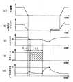
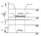
以下、制御装置130によるモータ121の制御の詳細について、図4に示すフローチャートおよび図5に示すタイムチャートを用いて説明する。
【0059】
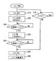
まず、エンジン10停止後にステップS10で、モータ121を停止状態とする。次に、ステップS20で、第1、第2所定時間t1、t2を決定する。即ち、上記図2(a)、図3(a)で示したように、予めメモリした第1所定時間t1、第2所定時間t2の外気温度に対する特性線図から現在の制御時における両所定時間t1、t2を決定する。そして、第2所定時間t2の計時がスタートされる。
【0060】
次に、ステップS30で、第2所定時間t2だけ経過したか否かを判定し、経過していればステップS40に進む。尚、否であればこのステップS30が繰返される。
【0061】
次に、ステップS40で、モータ121が作動される。この時、上記したように、第2所定時間t2の間に降下した吐出圧力Pdで第2圧縮機122を起動させるようにしている。この時、第1所定時間t1の計時がスタートされる。
【0062】
次に、ステップS50で、第1所定時間t1だけ経過したか否かを判定し、経過していればステップS60で、モータ121は停止される。尚、ステップS50で、否と判定されれば、このステップが繰返される。
【0063】
以上の構成および作動説明より、本実施形態における作用効果について説明する。
【0064】
本実施形態によれば、モータ121は、予め定めた第1所定時間t1以上、作動されることがないので、バッテリ上りを確実に防止することができる。尚、ここでは、第1所定時間t1を、繰返されるアイドリングに対して、平均的な値として定めているので、アイドリング時の冷房性能を平均的に確保することができる。
【0065】
そして、上記第1所定時間t1は、外気温度に応じて変化させるようにしているので、不要な電力の消費を抑制し、モータ121の消費電力を更に低減することができる。
【0066】
また、モータ121を作動させるまでに遅延時間として第2所定時間t2を設けているので、エンジン10作動時に得られていた吐出圧力Pが第2所定時間t2の間に順次低下することになる。この低下した吐出圧力Pdで第2圧縮機122のモータ121を起動させるので、エンジン10作動時の吐出圧力Pで起動するのに比べて第2圧縮機122の消費動力を低減させることができ、モータ121の消費電力を低減できる。これに合せて、モータ121の起動時の突入電流値を低減させることができるので、突入電流による関連部品の寿命低下防止や、バッテリ140の電圧降下抑制による補機類の誤作動防止を図ることができる。
【0067】
また、第2所定時間t2を外気温度に応じて変化させるようにしているので、不要な電力の消費を抑制し、更に消費電力、突入電流の低減ができる。
【0068】
尚、第1所定時間t1は、図2(b)に示すように、外気温度が所定値を越えて更に低くなると逆に長くなるように設定しても良い。そして、第2所定時間t2は、図3(b)に示すように、外気温度が所定値を越えて更に低くなると逆に短くなるように設定しても良い。これにより、冬場における車両窓ガラスへの防雲性を向上させることができる。
【0069】
また、第1、第2所定時間t1、t2は、外気温度に代えて冷凍サイクル装置110の冷房負荷に対応する変数として関係付けるものにしても良い。
【0070】
(第2実施形態)
本発明の第2実施形態を図6〜図8に示す。基本的な構成は上記第1実施形態に対して、図6に示すように、制御装置130には、バッテリ容量Cに応じてエンジン10の始動を要求するエンジン始動要求機能を持たせるようにしている。
【0071】
即ち、電流センサ140aからの信号に基づいて、バッテリ容量Cを演算するようにしており、このバッテリ容量Cが所定容量C1を下回った時に、モータ121を停止させ、エンジン10の作動を制御するエンジン制御装置11に対して、エンジン始動要求信号を出力しエンジン10を始動させるようにしたものである。
【0072】
図7、図8はモータ121の制御時におけるフローチャートおよびタイムチャートを示すものである。基本的な制御は、上記第1実施形態と同様に、ステップS10〜ステップS60が行われるが、同時にステップS70で、バッテリ容量Cをチェックするようにしている。即ち、エンジン10停止中にモータ121が作動されると、バッテリ140のバッテリ容量Cは、低下していくが、予め定めた所定容量C1を下回った時に、モータ121の作動経過時間が第1所定時間t1以内であっても、ステップS60で、モータ121は停止され、ステップS80で、エンジン制御装置11にエンジン始動要求信号が出力され、エンジン10を始動させるようにしている。
【0073】
これにより、エンジン10を駆動源として、圧縮機111が駆動されるので、冷房性能を確保しつつ、バッテリ上りを確実に防止できる。尚、エンジン10始動後は、バッテリ140の充電がなされる。
【0074】
(第3実施形態)
本発明の第3実施形態を図9に示す。第3実施形態は、上記第1実施形態に対して、モータ121停止後に、冷房温度に応じてエンジン10を始動するようにしたものである。尚、ここでは、制御装置130には、上記第2実施形態と同様に、エンジン始動要求機能を持たせるようにしている。
【0075】
まず、冷房装置100内の代表的な冷房温度を把握する部位(所定部位)として、ここでは蒸発器114と定め、上記図1で示した蒸発器温度センサ114aによって得られる後方空気温度(以下、蒸発器温度)Teのうち、冷房性能上の許容上限値を第1所定温度T1として予め設定するようにしている。
【0076】
そして、図9に示すように、エンジン10が停止し、第2所定時間t2経過後にモータ121が作動され、作動時間が第1所定時間t1を経過するとモータ121は停止される。その後エンジン10が長く停止状態にあるような場合、蒸発器温度Teは上昇していくことになるが、この蒸発器温度Teが第1所定温度T1を上回った時に、上記第2実施形態と同様に、エンジン10を始動させるようにしている。
【0077】
これにより、エンジン10停止時間が第1所定時間t1に対して長い場合でも、第1所定時間t1でモータ121を停止させバッテリ上りを防止し、且つ、エンジン10を駆動源として圧縮機111を作動させることで、冷房性能を確保することができる。
【0078】
(第4実施形態)
本発明の第4実施形態を図10〜図12に示す。第4実施形態は、冷房温度としての蒸発器温度Teに応じてモータ121のON−OFFおよびエンジン10の始動を行なうようにしたものである。
【0079】
まず、蒸発器温度Teにおいて、冷房性能上の許容上限値となる第1所定温度T1と許容下限値となる第2所定温度T2と両者の間の値となる第3所定温度T3を、図10(a)に示すように、外気温度に対応するような特性線図として予め定め、制御装置130にメモリするようにしている。
【0080】
そして、図11、図12に示すように、これらの各所定温度T1、T2、T3を判定条件としてモータ121のON−OFFおよびエンジン10の始動を行なう。
【0081】
図11に示す制御フローチャートは、第1実施形態における図4で示したものに対して、ステップS20をステップS21に置換え、ステップS31、S51、S61を追加したものとしており、他のステップは同一である。ここでは、主に、これら追加されたステップを中心にその制御の内容を説明する。
【0082】
まずステップS21で、第1、第2所定時間t1、t2に加えて、第1〜第3所定温度T1、T2、T3を予め定めた特性線図より決定する。
【0083】
次に、ステップS30で第2所定時間t2が経過した後に、ステップS31で、蒸発器温度Teが第3所定温度T3よりも高いか否かが判定され、否であればこのステップが繰返され、第2所定時間t2以降の時間が経過していく。この時、蒸発器温度Teは上昇していくことになり、蒸発器温度Teが第3所定温度T3を上回った時に、ステップS40でモータ121を作動させるようにしている。即ち、蒸発器温度Teが第3所定温度T3を上回るまでの温度上昇時間が、第2所定時間t2よりも長い場合は、この温度上昇時間が優先されて、モータ121が作動される訳である。
【0084】
次に、モータ121が作動されることによって蒸発器温度Teが逆に低下していくことになり、第1所定時間t1が経過するまでの間に蒸発器温度Teが第2所定温度T2を下回ったか否かの判定が、ステップS51において行われる。そして、蒸発器温度Teが第2所定温度T2を下回った時には、モータ121の作動時間が第1所定時間t1以内であっても、モータ121はステップS60で停止される。
【0085】
更に、蒸発器温度Teは再び上昇していくことになり、ステップS61で、その後の蒸発器温度Teが第1所定温度T1を上回ったか否かが判定され、上回った場合は、エンジン10を始動するようにしている。
【0086】
これにより、エンジン10停止後に第3所定温度T3までの冷房性能を確保しつつ、第2所定時間t2よりも長い時間分、モータ121の作動を行なわないようにできるので、更に消費電力の節約ができる。
【0087】
また、モータ121を作動させるタイミングを第3所定温度T3を基に決定できるので、第2所定時間t2を設定するよりも容易に対応できる。
【0088】
また、モータ121の作動によって蒸発器温度Teが早い時点で充分に低下するならば、それに応じてモータ121の作動を停止するので、更にバッテリ140の消費電力を低減することができる。
【0089】
そして、エンジン10始動後は、圧縮機111によって冷房性能が確保されることになる。
【0090】
尚、第1〜第3所定温度T1、T2、T3は、図10(b)に示すように、外気温度が所定値を越えて更に低くなると逆に低くなるように設定しても良い。これにより、冬場における車両窓ガラスへの防雲性を向上させることができる。
【0091】
また、第1〜第3所定温度T1、T2、T3は、外気温度に代えて冷凍サイクル装置110の冷房負荷に対応する変数として関係付けるものにしても良い。
【0092】
(第5実施形態)
本発明の第5実施形態を図13、図14に示す。第5実施形態は、第3所定時間t3を設定して、モータ121を停止させた後に、この第3所定時間t3だけエンジン10の始動を遅らせるようにしたものである。
【0093】
ここでは、モータ121を停止させてからのエンジン10を始動させるまでの遅延時間として第3所定時間t3を予め制御装置130にメモリするようにしている。この第3所定時間t3は、ここでは0.5秒以下としている。そして、図13、図14に示すように制御を行なう。(図13のステップS10〜ステップS50までは上記第1実施形態と同一であり、詳細説明は割愛する。)
第2所定時間t2経過後に、モータ121は作動され、この作動時間が計時される中で、ステップS52において、エンジン10の始動信号が発生されたか否かをチェックするようにしている。このチェックは、図6に示したエンジン制御装置11において、エンジン10を始動させる図示しないスタータへの作動信号が出力されたか否かを見るものである。
【0094】
ここで、第1所定時間t1が経過する以前にエンジン10の始動信号が発生されたと判定されると、ステップS60で、モータ121が停止され、同時にステップS81で、エンジン10への始動要求を行なう。この場合の始動要求は、モータ121を停止させた時点から、上記第3所定時間t3経過後にスタータを作動させてエンジン10を始動するようにしている。
【0095】
これにより、エンジン10を始動するためのスタータとモータ121とが同時に作動することがなく、バッテリ140の電圧降下を低減でき、補機類の誤作動を防止することができる。
【0096】
ここで、第3所定時間t3は、0.5秒以下となるように短い時間としているので、エンジン10始動までの時間を不要に延ばすことなく、また乗員に対しても停車から発進に至るスムースな運転を可能とすることができる。
【0097】
(第6実施形態)
本発明の第6実施形態を図15に示す。第6実施形態は、圧縮機111の吐出圧力Pに応じて、モータ121を作動するようにしたものである。
【0098】
ここでは、エンジン10停止後、モータ121を作動させるタイミングを圧縮機111の吐出圧力Pに応じて行なうようにしている。即ち、エンジン10によって駆動される圧縮機111の通常の吐出圧力Pよりも低い側で、且つ、冷房性能を許容できうる圧力値として予め定めた第1所定圧力P1を下回った時に、モータ121を作動させるようにしている。
【0099】
これにより、低下した第1吐出圧力P1で圧縮機122のモータ121を起動させてやれば、冷房性能を確保しつつ、上記第1実施形態と同様に、エンジン10作動時の吐出圧力Pで起動するのに比べて圧縮機122の消費動力を低減させることができ、モータ121の消費電力を低減できる。合せてモータ121の起動時の突入電流値を低減させることができ、突入電流による関連部品の寿命低下防止や、バッテリ140の電圧降下抑制による補機類の誤作動防止を図ることができる。
【0100】
(第7実施形態)
本発明の第7実施形態を図16に示す。第7実施形態では、エンジン10によって駆動される圧縮機111の吐出圧力Pが、エンジン10停止前に低下する側に制御されている場合、即ち、ここでは、圧縮機111がOFF状態とされている時は、エンジン10が停止された時点で、モータ121を作動させるようにしている。
【0101】
これにより、低下した吐出圧力Pで圧縮機122のモータ121を起動させてやれば、上記第1実施形態と同様に、エンジン10作動時の吐出圧力Pで起動するのに比べて圧縮機122の消費動力を低減させることができ、モータ121の消費電力を低減できる。合せてモータ121の起動時の突入電流値を低減させることができ、突入電流による関連部品の寿命低下防止や、バッテリ140の電圧降下抑制による補機類の誤作動防止を図ることができる。
【0102】
尚、圧縮機111は、ON−OFF制御のものに限らず、容量可変型のものとしても良い。
【0103】
(第8実施形態)
本発明の第8実施形態を図17に示す。第8実施形態は、車両が減速状態にあり、停車するまでの間に(例えば、所定車速V1を下回った時に)、エンジン10によって駆動される圧縮機111の吐出圧力Pを低下させるようにして、エンジン10が停止された後にモータ121を作動するようにしている。ここでは具体的には、圧縮機111をOFFにして、吐出量を低下させることで吐出圧力Pを低下させるようにしている。
【0104】
これにより、上記第7実施形態と同様の効果を得ることができる。
【0105】
(第9実施形態)
本発明の第9実施形態を図18に示す。第9実施形態は、上記第8実施形態に対して、図1で示した凝縮器112の送風機112aの送風量を増加させることで、吐出圧力Pを低下させるものとしている。
【0106】
これにより、凝縮器112での冷媒の冷却が促進され、モータ121を作動させる前に吐出圧力Pを低下させることができ、上記第7、第8実施形態と同様の効果を得ることができる。
【0107】
(第10実施形態)
本発明の第10実施形態を図19、図20に示す。第10実施形態は、エンジン10の停止前の冷凍サイクル装置110の冷房負荷が所定負荷よりも高い場合は、エマージェンシー対応として、モータ121を作動させないようにしたものである。
【0108】
ここでは、冷凍サイクル装置110の冷房負荷を圧縮機111の吐出圧力Pを代表変数として取りあげており、第6実施形態の図15で示した第1所定圧力P1よりも高い側に設定される第2所定圧力P2を判定値と定めている。
【0109】
具体的には、図19に示すように、エンジン10停止前の吐出圧力Pが第2所定圧力P2よりも高い場合、車両が停車してもエンジン始動要求信号をエンジン制御装置11に入力して、エンジン10を停止させないようにし、エンジン10を駆動源とする圧縮機111を継続して作動させるようにしている。(モータ121は作動させず。)
また、図20に示すように、エンジン10が停止となった場合でも、モータ121を作動させないようにしている。
【0110】
これにより、吐出圧力Pが第2所定圧力P2よりも高く、冷房負荷が非常に高いような場合は、エマージェンシー対応としてモータ121を完全に作動させないことで、極端なモータ121の消費電力を抑えて、バッテリ上りを確実に防止することができる。
【0111】
尚、図19に示すように、エンジン10を始動させる場合は、圧縮機111によって冷房性能を確保できる。
【0112】
また、冷凍サイクル装置110の冷房負荷としては、車両内気温度、蒸発器温度Te等を用いるようにしても良い。
【0113】
(その他の実施形態)
上記第1〜第10実施形態では、圧縮機は第1圧縮機111と第2圧縮機122とから成るように構成し、それぞれがエンジン10およびモータ121によって駆動されるものとして説明したが、これに限らず、図21に示すように、エンジン10およびモータ121を選択的に駆動源として作動する所謂ハイブリッドコンプレッサ111aとしても良い。
【図面の簡単な説明】
【図1】本発明の第1実施形態における全体構成を示す模式図である。
【図2】外気温度と第1所定時間との関係を示す(a)は第1パターン、(b)は第2パターンにおける特性線図である。
【図3】外気温度と第2所定時間との関係を示す(a)は第1パターン、(b)は第2パターンにおける特性線図である。
【図4】図1におけるモータの作動制御を示すフローチャートである。
【図5】図1における制御時の(a)は車速、(b)は吐出圧力、(c)はモータのON−OFF状態、(d)はモータの電流値を示すタイムチャートである。
【図6】本発明の第2実施形態における部分構成を示す模式図である。
【図7】図6におけるモータの作動制御を示すフローチャートである。
【図8】図6における制御時の(a)は車速、(b)はエンジン回転数、(c)は吐出圧力、(d)はモータのON−OFF状態、(e)はバッテリ容量、(f)は蒸発器温度を示すタイムチャートである。
【図9】本発明の第3実施形態における制御時の(a)は車速、(b)はエンジン回転数、(c)は吐出圧力、(d)はモータのON−OFF状態、(e)は蒸発器温度を示すタイムチャートである。
【図10】本発明の第4実施形態における外気温度と第1、第2、第3所定温度との関係を示す(a)は第1パターン、(b)は第2パターンにおける特性線図である。
【図11】第4実施形態におけるモータの作動制御を示すフローチャートである。
【図12】第4実施形態における(a)は車速、(b)はエンジン回転数、(c)は吐出圧力、(d)はモータのON−OFF状態、(e)は蒸発器温度を示すタイムチャートである
【図13】本発明の第5実施形態におけるモータの作動制御を示すフローチャートである。
【図14】第5実施形態における(a)は車速、(b)はエンジン回転数、(c)は吐出圧力、(d)はモータのON−OFF状態、(e)はスタータのON−OFF状態、(f)はバッテリ電圧を示すタイムチャートである。
【図15】本発明の第6実施形態における(a)は車速、(b)は吐出圧力、(c)はモータのON−OFF状態を示すタイムチャートである。
【図16】本発明の第7実施形態における(a)は車速、(b)は圧縮機のON−OFF状態、(c)は吐出圧力、(d)はモータのON−OFF状態を示すタイムチャートである。
【図17】本発明の第8実施形態における(a)は車速、(b)は圧縮機のON−OFF状態、(c)は吐出圧力、(d)はモータのON−OFF状態を示すタイムチャートである。
【図18】本発明の第9実施形態における(a)は車速、(b)は送風機の送風量、(c)は吐出圧力、(d)はモータのON−OFF状態を示すタイムチャートである。
【図19】本発明の第10実施形態の第1パターンにおける(a)は車速、(b)はエンジン回転数、(c)は吐出圧力、(d)はモータのON−OFF状態を示すタイムチャートである。
【図20】第10実施形態の第2パターンにおける(a)は車速、(b)はエンジン回転数、(c)は吐出圧力、(d)はモータのON−OFF状態を示すタイムチャートである。
【図21】その他の実施形態における全体構成を示す模式図である。
【符号の説明】
10 エンジン
11 エンジン制御装置
100 車両用冷房装置
110 冷凍サイクル装置
111 圧縮機(第1圧縮機)
111a ハイブリッドコンプレッサ
112 凝縮器
112a 送風機
114 蒸発器(所定部位)
121 モータ
122 圧縮機(第2圧縮機)
130 制御装置
140 バッテリ[0001]
BACKGROUND OF THE INVENTION
The present invention relates to a vehicle cooling device for a so-called idle stop vehicle that stops an engine when the vehicle is temporarily stopped during traveling.
[0002]
[Prior art]
As shown in Japanese Patent Application Laid-Open No. 2000-80348, a conventional vehicle cooling device has a compressor that uses an engine and a motor as drive sources in the device, and drives the compressor using the motor as a drive source when the engine is stopped. Among them, one provided with means for reducing the load on the motor is known. Specifically, the control is performed so that the air mix door is fixed at the full cool position during operation of the motor, is fixed to the inside air circulation mode side, or the evaporator freeze prevention temperature is increased by a predetermined value.
[0003]
As a result, the compression work required when driven by the engine is reduced, the power consumption of the compressor is reduced, and the load on the motor is reduced. Then, abnormal consumption of the battery power is prevented.
[0004]
[Problems to be solved by the invention]
However, although the power consumption of the compressor under steady use conditions can be reduced by the above technology, there are naturally variations in the use conditions of cooling by the occupant and the frequency of engine stoppage during driving, etc. Even under unsteady conditions such as when the engine is high or when the engine stop time is long, the charge capacity of the battery power source cannot be ensured by operating the compressor accordingly. That is, the battery goes up.
[0005]
SUMMARY OF THE INVENTION In view of the above problems, an object of the present invention is to provide a vehicle cooling device that ensures an average cooling performance at each stop and reliably prevents a battery from rising due to excessive operation of the motor when the engine is repeatedly stopped during traveling. Is to provide.
[0006]
[Means for Solving the Problems]
In order to achieve the above object, the present invention employs the following technical means.
[0007]
In the first aspect of the invention, the motor (10) is applied to a vehicle in which the engine (10) is stopped when the vehicle is temporarily stopped during traveling. 121) includes a refrigeration cycle apparatus (110) including a compressor (111, 122) that operates by receiving the driving force of 121), and a control device (130) that controls the operation of the motor (121). 110) In the vehicle cooling device in which the motor (121) is operated by the control device (130) to drive the compressor (122) when the engine (10) is stopped during operation, the control device (130) Is operated so that the cumulative operating time of the motor (121) during one stop is within the first predetermined time (t1).,
The first predetermined time (t1) is set to be shorter as the outside air temperature or the cooling load of the refrigeration cycle apparatus (110) is lower.It is characterized by that.
[0008]
Thereby, since the motor (121) is not operated for the first predetermined time (t1) or more, the battery can be reliably prevented from rising.
[0009]
Here, the first predetermined time (t1) may be determined from, for example, the idling frequency when simulated from the vehicle running conditions and the discharge depth (usage time) obtained from the number of times the battery (140) is used. As a result, it is possible to reliably prevent the battery from going up while ensuring an average cooling performance at each stop.
[0010]
And,If the first predetermined time (t1) is set to be shorter as the outside air temperature or the cooling load of the refrigeration cycle apparatus (110) is lower, the motor (121) can be operated according to the outside air temperature or the cooling load. Therefore, unnecessary power consumption can be suppressed, and the power consumption of the motor (121) can be further reduced.
[0011]
Further claims2As described in the invention, the first predetermined time (t1) is set to be longer when the outside air temperature or the cooling load exceeds a predetermined value and becomes longer. The haze can be improved.
[0012]
Claim3In the invention described in (1), the control device (130) has an engine start request function for requesting the engine control device (11) for controlling the operation of the engine (10) to start the engine (10). When the motor (121) is operated by the control device (130) and the battery capacity (C) of the battery (140) falls below the predetermined capacity (C1), the control device (130) Even if the accumulated operation time is within the first predetermined time (t1), the motor (121) is stopped at that time, and the engine (10) is started by the engine start request function. .
[0013]
Thereby, since the compressor (111) is driven using the engine (10) as a drive source, it is possible to reliably prevent the battery from rising while ensuring the cooling performance. The
[0014]
Claim4In the invention described in the above, the engine (10) is in a stopped state even after the cumulative operating time of the motor (121) has passed the first predetermined time (t1) and the motor (121) is stopped by the control device (130). Yes, when the cooling temperature at the predetermined part (114) exceeds the first predetermined temperature (T1), the control device (130) starts the engine (10) by the engine start request function. Yes.
[0015]
Thus, even when the engine (10) stop time is longer than the first predetermined time (t1), the motor (121) is stopped at the first predetermined time (t1) to prevent the battery from rising, and the engine (10 ) Is used as a drive source to actuate the compressor (111), thereby ensuring cooling performance.
[0016]
Claim5In the invention described inThe control device (130) operates so that the cumulative operation time of the motor (121) during one stop is within the first predetermined time (t1),
When the motor (121) is operated by the control device (130) and the cooling temperature at the predetermined portion (114) falls below the second predetermined temperature (T2), the control device (130) Even if the cumulative operation time is within the first predetermined time (t1), the motor (121) is stopped at that time.
[0017]
Accordingly, if the cooling temperature is sufficiently lowered at an early point, the operation of the motor (121) is stopped accordingly, so that the power consumption of the battery (140) can be further reduced.
[0018]
Claim6In the present invention, the control device (130) operates the motor (121) after a second predetermined time (t2) has elapsed since the engine (10) stopped.,
The control device (130) operates so that the cumulative operation time of the motor (121) during one stop is within the first predetermined time (t1).It is characterized by that.
[0019]
As a result, the discharge pressure (P) obtained when the engine (10) is operated is sequentially decreased during the second predetermined time (t2). Since the motor (121) of the compressor (122) has only to be started up with the reduced discharge pressure (Pd), the compressor can be compared with starting up with the discharge pressure (P) when the engine (10) is operating. The power consumption of (122) can be reduced, and the power consumption of the motor (121) can be reduced. In accordance with this, since the inrush current value at the start of the motor (121) can be reduced, the lifespan of related parts due to the inrush current can be prevented, and the auxiliary equipment malfunctions by suppressing the voltage drop of the battery (140). Prevention can be achieved.
[0020]
Where the claim7If the second predetermined time (t2) is set to be longer as the outside air temperature or the cooling load of the refrigeration cycle apparatus (110) is lower as in the invention described in the above, the motor is set according to the outside air temperature or the cooling load. Since (121) can be operated, unnecessary power consumption can be suppressed, and the power consumption and inrush current of the motor (121) can be further reduced.
[0021]
Claims8If the second predetermined time (t2) is set so as to be shortened when the outside air temperature or the cooling load is further reduced beyond the predetermined value, the second predetermined time (t2) is claimed.2As in the invention described in (1), it is possible to improve the cloud resistance to the vehicle window glass in winter.
[0022]
Claim9In the invention described in the above, the temperature rise time from when the engine (10) is stopped until the cooling temperature at the predetermined portion (114) exceeds the third predetermined temperature (T3) is longer than the second predetermined time (t2). In this case, the controller (130) is characterized in that the motor (121) is operated with priority given to the temperature rise time over the second predetermined time (t2).
[0023]
As a result, it is possible to prevent the motor (121) from operating for a time longer than the second predetermined time (t2) while ensuring the cooling performance up to the third predetermined temperature (T3). You can save.
[0024]
Moreover, since the timing which operates a motor (121) can be determined based on 3rd predetermined temperature (T3), it can respond easily rather than setting 2nd predetermined time (t2).
[0025]
Claim10In the invention described inThe control device (130) operates so that the cumulative operation time of the motor (121) during one stop is within the first predetermined time (t1),
When the engine (10) is started from the stopped state and the motor (121) is operating within the first predetermined time (t1), the control device (130) stops the motor (121). The engine start request function is characterized in that the engine (10) is started after a third predetermined time (t3) has elapsed since that time.
[0026]
Thereby, the starter for starting the engine (10) and the motor (121) do not operate at the same time, the voltage drop of the battery (140) can be reduced, and the malfunction of the auxiliary machinery can be prevented.Inwear.
[0027]
Where the claim11As described in the invention, the third predetermined time (t3) is preferably 0.5 seconds or less.
[0028]
Thereby, it is possible to enable a smooth operation from the stop to the start of the occupant without unnecessarily extending the time until the engine (10) is started.
[0029]
Claim12When the discharge pressure (P) by the compressor (111) operating the engine (10) falls below the first predetermined pressure (P1) after the engine (10) is stopped, the control device (130) To operate the motor (121),
The control device (130) operates so that the cumulative operation time of the motor (121) during one stop is within the first predetermined time (t1).It is characterized by that.
[0030]
Claim13In the invention described in (1), the control device (130) has a control function of varying the discharge pressure (P) when the compressor (111) is driven by the engine (10), and the engine (10) is stopped. When the discharge pressure (P) of the compressor (111) driven by the engine (10) is controlled to be decreased before by the control device (130), the control device (130) ) Is stopped when the motor (121) is activated.,
The control device (130) operates so that the cumulative operation time of the motor (121) during one stop is within the first predetermined time (t1).It is characterized by that.
[0031]
Claim14In the invention described in (1), the control device (130) has a control function of varying the discharge pressure (P) when the compressor (111) is driven by the engine (10), and the vehicle is in a decelerating state. Yes, until the vehicle stops, the control device (130) reduces the discharge pressure (P) of the compressor (111) driven by the engine (10) from the previous value, and the engine (10) The motor (121) is operated after being stopped.
[0032]
Claims15, Claims16As described in the invention, the discharge amount of the compressor (111) is reduced, or the blower amount of the blower (112a) that blows air to the condenser (112) provided in the refrigeration cycle device (110) is increased. By doing so, the discharge pressure (P) is preferably lowered.
[0033]
Claim12~ Claim16According to the invention described in
[0037]
[0038]
Further claims18As described in the invention, the compressor (111) may be a hybrid compressor (111a) that selectively operates using the engine (10) and the motor (121) as drive sources.
[0039]
In addition, the code | symbol in the bracket | parenthesis of each said means shows a corresponding relationship with the specific means of embodiment description mentioned later.
[0040]
DETAILED DESCRIPTION OF THE INVENTION
(First embodiment)
A first embodiment of the present invention is shown in FIGS. 1 to 5, and a specific configuration will be described with reference to FIG.
[0041]
The
[0042]
The
[0043]
The
[0044]
Similarly, the
[0045]
The
[0046]
A lead wire portion connected from the
[0047]
Next, the structure of the
[0048]
The
Further, of course, the
[0049]
In the present embodiment, a control program for effectively operating the
[0050]
First, the cumulative operating time for operating the
[0051]
The first predetermined time t1 is set so as to change according to the outside air temperature as shown in FIG. 2A, and this characteristic diagram is stored in the
[0052]
Next, a delay time is provided so that the
[0053]
As shown in FIG. 3A, the second predetermined time t2 is set so as to change according to the outside air temperature, and this characteristic diagram is stored in the
[0054]
A control program incorporating the first and second predetermined times t1 and t2 is stored in memory so that the operation of the
[0055]
The operation of the present embodiment based on the above configuration will be described.
[0056]
When the vehicle is traveling, that is, when the
[0057]
However, since the applicable vehicle is an idle stop vehicle, the
[0058]
Hereinafter, details of control of the
[0059]
First, after the
[0060]
Next, in step S30, it is determined whether or not the second predetermined time t2 has elapsed. If it has elapsed, the process proceeds to step S40. If no, step S30 is repeated.
[0061]
Next, in step S40, the
[0062]
Next, in step S50, it is determined whether or not the first predetermined time t1 has elapsed. If it has elapsed, the
[0063]
From the above configuration and operation description, the operation and effect of the present embodiment will be described.
[0064]
According to the present embodiment, since the
[0065]
And since the said 1st predetermined time t1 is made to change according to outside temperature, consumption of unnecessary electric power can be suppressed and the power consumption of the
[0066]
Further, since the second predetermined time t2 is provided as a delay time until the
[0067]
Further, since the second predetermined time t2 is changed according to the outside air temperature, it is possible to suppress unnecessary power consumption and further reduce power consumption and inrush current.
[0068]
Note that, as shown in FIG. 2B, the first predetermined time t1 may be set to become longer when the outside air temperature becomes lower than a predetermined value. And as shown in FIG.3 (b), you may set the 2nd predetermined time t2 so that it may become conversely short when outside temperature exceeds a predetermined value and becomes still lower. Thereby, the cloud-proof property to the vehicle window glass in winter can be improved.
[0069]
Further, the first and second predetermined times t1 and t2 may be related as variables corresponding to the cooling load of the
[0070]
(Second Embodiment)
A second embodiment of the present invention is shown in FIGS. As shown in FIG. 6, the basic configuration of the first embodiment is that the
[0071]
That is, the battery capacity C is calculated based on the signal from the
[0072]
7 and 8 are a flowchart and a time chart when the
[0073]
Thereby, since the
[0074]
(Third embodiment)
A third embodiment of the present invention is shown in FIG. In the third embodiment, the
[0075]
First, as a part (predetermined part) for grasping a typical cooling temperature in the
[0076]
Then, as shown in FIG. 9, the
[0077]
Thus, even when the
[0078]
(Fourth embodiment)
A fourth embodiment of the present invention is shown in FIGS. In the fourth embodiment, the
[0079]
First, at the evaporator temperature Te, a first predetermined temperature T1 that is an allowable upper limit value for cooling performance, a second predetermined temperature T2 that is an allowable lower limit value, and a third predetermined temperature T3 that is a value between them are shown in FIG. As shown in (a), a characteristic diagram corresponding to the outside air temperature is determined in advance and stored in the
[0080]
Then, as shown in FIGS. 11 and 12, the
[0081]
The control flowchart shown in FIG. 11 is obtained by replacing step S20 with step S21 and adding steps S31, S51, and S61 to the one shown in FIG. 4 in the first embodiment, and other steps are the same. is there. Here, the contents of the control will be mainly described focusing on these added steps.
[0082]
First, in step S21, in addition to the first and second predetermined times t1 and t2, first to third predetermined temperatures T1, T2, and T3 are determined from a predetermined characteristic diagram.
[0083]
Next, after the second predetermined time t2 has elapsed in step S30, in step S31, it is determined whether the evaporator temperature Te is higher than the third predetermined temperature T3. If not, this step is repeated. The time after the second predetermined time t2 elapses. At this time, the evaporator temperature Te rises, and when the evaporator temperature Te exceeds the third predetermined temperature T3, the
[0084]
Next, when the
[0085]
Further, the evaporator temperature Te is increased again. In step S61, it is determined whether or not the subsequent evaporator temperature Te exceeds the first predetermined temperature T1, and if it exceeds, the
[0086]
As a result, it is possible to prevent the
[0087]
In addition, since the timing for operating the
[0088]
Further, if the evaporator temperature Te decreases sufficiently at an early point due to the operation of the
[0089]
After the
[0090]
Note that the first to third predetermined temperatures T1, T2, and T3 may be set so as to decrease as the outside air temperature further decreases beyond a predetermined value, as shown in FIG. 10B. Thereby, the cloud-proof property to the vehicle window glass in winter can be improved.
[0091]
The first to third predetermined temperatures T1, T2, and T3 may be related as variables corresponding to the cooling load of the
[0092]
(Fifth embodiment)
A fifth embodiment of the present invention is shown in FIGS. In the fifth embodiment, after the third predetermined time t3 is set and the
[0093]
Here, a third predetermined time t3 is stored in advance in the
After the second predetermined time t2 has elapsed, the
[0094]
If it is determined that the start signal of the
[0095]
Thereby, the starter for starting the
[0096]
Here, since the third predetermined time t3 is set to a short time so as to be 0.5 seconds or less, the time required for starting the
[0097]
(Sixth embodiment)
A sixth embodiment of the present invention is shown in FIG. In the sixth embodiment, the
[0098]
Here, after the
[0099]
As a result, if the
[0100]
(Seventh embodiment)
A seventh embodiment of the present invention is shown in FIG. In the seventh embodiment, when the discharge pressure P of the
[0101]
As a result, if the
[0102]
The
[0103]
(Eighth embodiment)
FIG. 17 shows an eighth embodiment of the present invention. In the eighth embodiment, the discharge pressure P of the
[0104]
Thereby, the same effect as that of the seventh embodiment can be obtained.
[0105]
(Ninth embodiment)
FIG. 18 shows a ninth embodiment of the invention. In the ninth embodiment, the discharge pressure P is reduced by increasing the amount of air blown from the
[0106]
Thereby, cooling of the refrigerant in the
[0107]
(10th Embodiment)
A tenth embodiment of the present invention is shown in FIGS. In the tenth embodiment, when the cooling load of the
[0108]
Here, the cooling load of the
[0109]
Specifically, as shown in FIG. 19, when the discharge pressure P before stopping the
Further, as shown in FIG. 20, even when the
[0110]
Thereby, when the discharge pressure P is higher than the second predetermined pressure P2 and the cooling load is very high, the power consumption of the
[0111]
As shown in FIG. 19, when the
[0112]
Further, as the cooling load of the
[0113]
(Other embodiments)
In the first to tenth embodiments, the compressor is configured to include the
[Brief description of the drawings]
FIG. 1 is a schematic diagram showing an overall configuration in a first embodiment of the present invention.
2A is a characteristic diagram of a first pattern, and FIG. 2B is a characteristic diagram of a second pattern showing a relationship between an outside air temperature and a first predetermined time.
3A is a characteristic diagram of the first pattern, and FIG. 3B is a characteristic diagram of the second pattern showing the relationship between the outside air temperature and the second predetermined time.
4 is a flowchart showing operation control of the motor in FIG. 1. FIG.
5A is a time chart showing a vehicle speed, FIG. 5B is a discharge pressure, FIG. 5C is a motor ON-OFF state, and FIG. 5D is a time chart showing a motor current value.
FIG. 6 is a schematic diagram showing a partial configuration in a second embodiment of the present invention.
7 is a flowchart showing operation control of the motor in FIG. 6. FIG.
8A is the vehicle speed, FIG. 6B is the engine speed, FIG. 8C is the discharge pressure, FIG. 8D is the motor ON-OFF state, FIG. 8E is the battery capacity, f) is a time chart showing the evaporator temperature.
9A is a vehicle speed, FIG. 9B is an engine speed, FIG. 9C is a discharge pressure, FIG. 9D is a motor ON-OFF state, and FIG. Is a time chart showing the evaporator temperature.
FIGS. 10A and 10B are graphs showing the relationship between the outside air temperature and the first, second, and third predetermined temperatures in the fourth embodiment of the present invention, wherein FIG. is there.
FIG. 11 is a flowchart showing operation control of a motor in the fourth embodiment.
12A is a vehicle speed, FIG. 12B is an engine speed, FIG. 12C is a discharge pressure, FIG. 12D is a motor ON-OFF state, and FIG. 12E is an evaporator temperature. It is a time chart
FIG. 13 is a flowchart showing operation control of a motor in the fifth embodiment of the present invention.
14A is a vehicle speed, FIG. 14B is an engine speed, FIG. 14C is a discharge pressure, FIG. 14D is a motor ON-OFF state, and FIG. 14E is a starter ON-OFF. State (f) is a time chart showing the battery voltage.
15A is a time chart showing a vehicle speed, FIG. 15B is a discharge pressure, and FIG. 15C is a time chart showing an ON / OFF state of a motor in a sixth embodiment of the present invention.
16A is a vehicle speed, FIG. 16B is a compressor ON-OFF state, FIG. 16C is a discharge pressure, and FIG. 16D is a time showing a motor ON-OFF state. It is a chart.
17A is a vehicle speed, FIG. 17B is a compressor ON-OFF state, FIG. 17C is a discharge pressure, and FIG. 17D is a motor ON / OFF time. It is a chart.
18A is a time chart showing the vehicle speed, FIG. 18B is the air flow rate of the blower, FIG. 18C is the discharge pressure, and FIG. 18D is the time chart showing the ON / OFF state of the motor. .
19A is a vehicle speed, FIG. 19B is an engine speed, FIG. 19C is a discharge pressure, and FIG. 19D is a time indicating the ON / OFF state of the motor in the first pattern of the tenth embodiment of the present invention. It is a chart.
20A is a time chart showing a vehicle speed, FIG. 20B is an engine speed, FIG. 20C is a discharge pressure, and FIG. 20D is a time chart showing an ON / OFF state of the motor in the second pattern of the tenth embodiment. .
FIG. 21 is a schematic diagram showing an overall configuration in another embodiment.
[Explanation of symbols]
10 engine
11 Engine control device
100 Cooling device for vehicle
110 Refrigeration cycle equipment
111 Compressor (first compressor)
111a Hybrid compressor
112 Condenser
112a blower
114 Evaporator (predetermined part)
121 motor
122 Compressor (second compressor)
130 Controller
140 battery
Claims (18)
Translated fromJapanese前記エンジン(10)およびバッテリ(140)を電源とするモータ(121)の駆動力を受けて作動する圧縮機(111、122)を含む冷凍サイクル装置(110)と、
前記モータ(121)の作動を制御する制御装置(130)とが設けられ、
前記冷凍サイクル装置(110)作動時に、前記エンジン(10)が停止した場合、前記圧縮機(122)を駆動させるために、前記制御装置(130)によって前記モータ(121)が作動される車両用冷房装置において、
前記制御装置(130)は、1回の停車中における前記モータ(121)の累積作動時間が第1所定時間(t1)以内となるように作動させ、
前記第1所定時間(t1)は、外気温度あるいは前記冷凍サイクル装置(110)の冷房負荷が低いほど、短くなるように設定されることを特徴とする車両用冷房装置。When the vehicle is temporarily stopped during traveling, the engine (10) is applied to a vehicle that is stopped,
A refrigeration cycle apparatus (110) including a compressor (111, 122) that operates by receiving driving force of a motor (121) that uses the engine (10) and a battery (140) as power sources;
A control device (130) for controlling the operation of the motor (121),
When the engine (10) is stopped when the refrigeration cycle device (110) is operated, the motor (121) is operated by the control device (130) to drive the compressor (122). In the air conditioner,
The control device (130) is operated so that a cumulative operation time of the motor (121) during one stop is within a first predetermined time (t1),
The vehicle cooling device according toclaim 1, wherein the first predetermined time (t1) is set to be shorter as the outside air temperature or the cooling load of the refrigeration cycle device (110) is lower .
前記制御装置(130)によって、前記モータ(121)が作動され、前記バッテリ(140)のバッテリ容量(C)が、所定容量(C1)を下回った時に、
前記制御装置(130)は、前記モータ(121)の前記累積作動時間が前記第1所定時間(t1)以内であっても、その時点で前記モータ(121)を停止させると共に、前記エンジン始動要求機能によって、前記エンジン(10)を始動させるようにしたことを特徴とする請求項1または請求項2に記載の車両用冷房装置。The control device (130) has an engine start request function for requesting the engine control device (11) for controlling the operation of the engine (10) to start the engine (10),
When the motor (121) is operated by the controller (130) and the battery capacity (C) of the battery (140) falls below a predetermined capacity (C1),
The control device (130) stops the motor (121) at the time even if the cumulative operation time of the motor (121) is within the first predetermined time (t1), and also requests the engine start The vehicle cooling device according to claim 1or2 , wherein the engine (10) is started by a function.
前記モータ(121)の前記累積作動時間が前記第1所定時間(t1)を経過し、前記制御装置(130)によって前記モータ(121)が停止された後も前記エンジン(10)が停止状態にあり、所定部位(114)における冷房温度が第1所定温度(T1)を上回った時に、
前記制御装置(130)は、前記エンジン始動要求機能によって、前記エンジン(10)を始動させるようにしたことを特徴とする請求項1または請求項2に記載の車両用冷房装置。The control device (130) has an engine start request function for requesting the engine control device (11) for controlling the operation of the engine (10) to start the engine (10),
The engine (10) is stopped even after the cumulative operating time of the motor (121) has passed the first predetermined time (t1) and the motor (121) is stopped by the control device (130). Yes, when the cooling temperature at the predetermined portion (114) exceeds the first predetermined temperature (T1),
The vehicle cooling device according to claim 1or2, wherein the control device (130) starts the engine (10) by the engine start request function.
前記エンジン(10)およびバッテリ(140)を電源とするモータ(121)の駆動力を受けて作動する圧縮機(111、122)を含む冷凍サイクル装置(110)と、
前記モータ(121)の作動を制御する制御装置(130)とが設けられ、
前記冷凍サイクル装置(110)作動時に、前記エンジン(10)が停止した場合、前記圧縮機(122)を駆動させるために、前記制御装置(130)によって前記モータ(121)が作動される車両用冷房装置において、
前記制御装置(130)は、1回の停車中における前記モータ(121)の累積作動時間が第1所定時間(t1)以内となるように作動させ、
前記制御装置(130)によって前記モータ(121)が作動されており、前記所定部位(114)における冷房温度が、第2所定温度(T2)を下回った時に、
前記制御装置(130)は、前記モータ(121)の前記累積作動時間が前記第1所定時間(t1)以内であっても、その時点で前記モータ(121)を停止するようにしたことを特徴とする車両用冷房装置。When the vehicle is temporarily stopped during traveling, the engine (10) is applied to a vehicle that is stopped,
A refrigeration cycle apparatus (110) including a compressor (111, 122) that operates by receiving driving force of a motor (121) that uses the engine (10) and a battery (140) as power sources;
A control device (130) for controlling the operation of the motor (121),
When the engine (10) is stopped when the refrigeration cycle device (110) is operated, the motor (121) is operated by the control device (130) to drive the compressor (122). In the air conditioner,
The control device (130) is operated so that a cumulative operation time of the motor (121) during one stop is within a first predetermined time (t1),
When the motor (121) is operated by the controller (130) and the cooling temperature at the predetermined portion (114) is lower than a second predetermined temperature (T2),
The control device (130) is configured to stop the motor (121) at that time even if the cumulative operation time of the motor (121) is within the first predetermined time (t1). thecar dual air conditioning systemyou.
前記エンジン(10)およびバッテリ(140)を電源とするモータ(121)の駆動力を受けて作動する圧縮機(111、122)を含む冷凍サイクル装置(110)と、
前記モータ(121)の作動を制御する制御装置(130)とが設けられ、
前記冷凍サイクル装置(110)作動時に、前記エンジン(10)が停止した場合、前記圧縮機(122)を駆動させるために、前記制御装置(130)によって前記モータ(121)が作動される車両用冷房装置において、
前記制御装置(130)は、前記エンジン(10)が停止してから、第2所定時間(t2)経過した後に前記モータ(121)を作動させるようにし、
前記制御装置(130)は、1回の停車中における前記モータ(121)の累積作動時間が第1所定時間(t1)以内となるように作動させることを特徴とする車両用冷房装置。When the vehicle is temporarily stopped during traveling, the engine (10) is applied to a vehicle that is stopped,
A refrigeration cycle apparatus (110) including a compressor (111, 122) that operates by receiving driving force of a motor (121) that uses the engine (10) and a battery (140) as power sources;
A control device (130) for controlling the operation of the motor (121),
When the engine (10) is stopped when the refrigeration cycle device (110) is operated, the motor (121) is operated by the control device (130) to drive the compressor (122). In the air conditioner,
The controller (130) operates the motor (121) after a second predetermined time (t2) has elapsed since the engine (10) was stopped,
Wherein the control device (130), onecar dual cooling apparatuscumulative operating timeyou wherein theactuating so that within the first predetermined time (t1) of said motor (121) in the stop.
前記制御装置(130)は、前記第2所定時間(t2)に対して前記温度上昇時間を優先して、前記モータ(121)を作動させるようにしたことを特徴とする請求項6に記載の車両用冷房装置。When the temperature rise time from when the engine (10) is stopped until the cooling temperature at the predetermined portion (114) exceeds the third predetermined temperature (T3) is longer than the second predetermined time (t2),
The control device (130) according to claim6 , wherein the motor (121) is operated with priority given to the temperature rise time with respect to the second predetermined time (t2). Air conditioner for vehicles.
前記エンジン(10)およびバッテリ(140)を電源とするモータ(121)の駆動力を受けて作動する圧縮機(111、122)を含む冷凍サイクル装置(110)と、
前記モータ(121)の作動を制御する制御装置(130)とが設けられ、
前記冷凍サイクル装置(110)作動時に、前記エンジン(10)が停止した場合、前記圧縮機(122)を駆動させるために、前記制御装置(130)によって前記モータ(121)が作動される車両用冷房装置において、
前記制御装置(130)は、1回の停車中における前記モータ(121)の累積作動時間が第1所定時間(t1)以内となるように作動させ、
前記制御装置(130)は、前記エンジン(10)の作動を制御するエンジン制御装置(11)に対して、前記エンジン(10)の始動を要求するエンジン始動要求機能を有しており、
前記エンジン(10)が停止状態から始動する際に、前記モータ(121)が前記第1所定時間(t1)の範囲内で作動している場合、
前記制御装置(130)は、前記モータ(121)を停止させると共に、前記エンジン始動要求機能によって、その時点から第3所定時間(t3)経過の後に前記エンジン(10)を始動させるようにしたことを特徴とする車両用冷房装置。When the vehicle is temporarily stopped during traveling, the engine (10) is applied to a vehicle that is stopped,
A refrigeration cycle apparatus (110) including a compressor (111, 122) that operates by receiving driving force of a motor (121) that uses the engine (10) and a battery (140) as power sources;
A control device (130) for controlling the operation of the motor (121),
When the engine (10) is stopped when the refrigeration cycle device (110) is operated, the motor (121) is operated by the control device (130) to drive the compressor (122). In the air conditioner,
The control device (130) is operated so that a cumulative operation time of the motor (121) during one stop is within a first predetermined time (t1),
The control device (130) has an engine start request function for requesting the engine control device (11) for controlling the operation of the engine (10) to start the engine (10),
When the engine (10) starts from a stopped state, the motor (121) is operating within the first predetermined time (t1),
The control device (130) stops the motor (121), and starts the engine (10) after a third predetermined time (t3) has elapsed from that time by the engine start request function.car dual air conditioning systemshall be the features a.
前記エンジン(10)およびバッテリ(140)を電源とするモータ(121)の駆動力を受けて作動する圧縮機(111、122)を含む冷凍サイクル装置(110)と、
前記モータ(121)の作動を制御する制御装置(130)とが設けられ、
前記冷凍サイクル装置(110)作動時に、前記エンジン(10)が停止した場合、前記圧縮機(122)を駆動させるために、前記制御装置(130)によって前記モータ(121)が作動される車両用冷房装置において、
前記エンジン(10)作動中の前記圧縮機(111)による吐出圧力(P)が、前記エンジン(10)停止後に、第1所定圧力(P1)を下回った時に、
前記制御装置(130)は、前記モータ(121)を作動させるようにし、
前記制御装置(130)は、1回の停車中における前記モータ(121)の累積作動時間が第1所定時間(t1)以内となるように作動させることを特徴とする車両用冷房装置。When the vehicle is temporarily stopped during traveling, the engine (10) is applied to a vehicle that is stopped,
A refrigeration cycle apparatus (110) including a compressor (111, 122) that operates by receiving driving force of a motor (121) that uses the engine (10) and a battery (140) as power sources;
A control device (130) for controlling the operation of the motor (121),
When the engine (10) is stopped when the refrigeration cycle device (110) is operated, the motor (121) is operated by the control device (130) to drive the compressor (122). In the air conditioner,
When the discharge pressure (P) by the compressor (111) during operation of the engine (10) is lower than the first predetermined pressure (P1) after the engine (10) is stopped,
The controller (130) operates the motor (121);
Wherein the control device (130), onecar dual cooling apparatuscumulative operating timeyou wherein theactuating so that within the first predetermined time (t1) of said motor (121) in the stop.
前記エンジン(10)およびバッテリ(140)を電源とするモータ(121)の駆動力を受けて作動する圧縮機(111、122)を含む冷凍サイクル装置(110)と、
前記モータ(121)の作動を制御する制御装置(130)とが設けられ、
前記冷凍サイクル装置(110)作動時に、前記エンジン(10)が停止した場合、前記圧縮機(122)を駆動させるために、前記制御装置(130)によって前記モータ(121)が作動される車両用冷房装置において、
前記制御装置(130)は、前記圧縮機(111)が前記エンジン(10)によって駆動される場合の前記吐出圧力(P)を可変する制御機能を有しており、
前記エンジン(10)停止前に、前記エンジン(10)によって駆動される前記圧縮機(111)の前記吐出圧力(P)が、前記制御装置(130)によって低下する側に制御されている場合、
前記制御装置(130)は、前記エンジン(10)が停止された時点で前記モータ(121)を作動させるようにし、
前記制御装置(130)は、1回の停車中における前記モータ(121)の累積作動時間が第1所定時間(t1)以内となるように作動させることを特徴とする車両用冷房装置。When the vehicle is temporarily stopped during traveling, the engine (10) is applied to a vehicle that is stopped,
A refrigeration cycle apparatus (110) including a compressor (111, 122) that operates by receiving driving force of a motor (121) that uses the engine (10) and a battery (140) as power sources;
A control device (130) for controlling the operation of the motor (121),
When the engine (10) is stopped when the refrigeration cycle device (110) is operated, the motor (121) is operated by the control device (130) to drive the compressor (122). In the air conditioner,
The control device (130) has a control function of varying the discharge pressure (P) when the compressor (111) is driven by the engine (10),
When the discharge pressure (P) of the compressor (111) driven by the engine (10) is controlled to be decreased by the control device (130) before the engine (10) is stopped,
The control device (130) operates the motor (121) when the engine (10) is stopped,
Wherein the control device (130), onecar dual cooling apparatuscumulative operating timeyou wherein theactuating so that within the first predetermined time (t1) of said motor (121) in the stop.
前記エンジン(10)およびバッテリ(140)を電源とするモータ(121)の駆動力を受けて作動する圧縮機(111、122)を含む冷凍サイクル装置(110)と、
前記モータ(121)の作動を制御する制御装置(130)とが設けられ、
前記冷凍サイクル装置(110)作動時に、前記エンジン(10)が停止した場合、前記圧縮機(122)を駆動させるために、前記制御装置(130)によって前記モータ(121)が作動される車両用冷房装置において、
前記制御装置(130)は、前記圧縮機(111)が前記エンジン(10)によって駆動される場合の前記吐出圧力(P)を可変する制御機能を有しており、
前記車両が減速状態にあり、停車するまでの間に、前記制御装置(130)は、前記エンジン(10)によって駆動される前記圧縮機(111)の前記吐出圧力(P)をそれ以前の値より低下させると共に、前記エンジン(10)が停止された後に前記モータ(121)を作動させるようにしたことを特徴とする車両用冷房装置。When the vehicle is temporarily stopped during traveling, the engine (10) is applied to a vehicle that is stopped,
A refrigeration cycle apparatus (110) including a compressor (111, 122) that operates by receiving driving force of a motor (121) that uses the engine (10) and a battery (140) as power sources;
A control device (130) for controlling the operation of the motor (121),
When the engine (10) is stopped when the refrigeration cycle device (110) is operated, the motor (121) is operated by the control device (130) to drive the compressor (122). In the air conditioner,
The control device (130) has a control function of varying the discharge pressure (P) when the compressor (111) is driven by the engine (10),
Before the vehicle is decelerated and stops, the control device (130) sets the discharge pressure (P) of the compressor (111) driven by the engine (10) to a previous value. The vehicle air conditioner is further lowered and the motor (121) is operated after the engine (10) is stopped.
前記制御手段(130)は、前記送風機(112a)の送風量を増加させることにより、前記吐出圧力(P)を低下させるようにしたことを特徴とする請求項14に記載の車両用冷房装置。The condenser (112) provided in the refrigeration cycle device (110) is provided with a blower (112a) for blowing air to the condenser (112), and the control device (130) is provided with the blower (112a). )
The cooling device for a vehicle according to claim14 , wherein the control means (130) decreases the discharge pressure (P) by increasing an air flow rate of the blower (112a).
前記第1圧縮機(111)は、前記エンジン(10)を駆動源として作動するものとし、
前記第2圧縮機(122)は、前記モータ(121)を駆動源として作動するものとし、
前記第1圧縮機(111)および前記第2圧縮機(121)は、前記冷凍サイクル装置(110)内に並列に接続されるようにしたことを特徴とする請求項1〜請求項16のいずれかに記載の車両用冷房装置。The compressor (111) comprises a first compressor (111) and a second compressor (122),
The first compressor (111) operates using the engine (10) as a drive source,
The second compressor (122) operates using the motor (121) as a drive source,
It said first compressor (111) and said second compressor (121), one of the claims 1 to16, characterized in that it has to be connected in parallel to the refrigeration cycle device (110) The vehicle cooling device according to claim 1.
Priority Applications (4)
| Application Number | Priority Date | Filing Date | Title |
|---|---|---|---|
| JP2001206890AJP4613455B2 (en) | 2001-07-06 | 2001-07-06 | Vehicle cooling system |
| US10/132,764US6981544B2 (en) | 2001-04-27 | 2002-04-26 | Air-conditioning apparatus including motor-driven compressor for idle stopping vehicles |
| DE10218731ADE10218731A1 (en) | 2001-04-27 | 2002-04-26 | Air conditioner with a drive-driven compressor for vehicles to stop without an engine |
| US11/029,404US7287583B2 (en) | 2001-04-27 | 2005-01-06 | Air-conditioning apparatus including motor-driven compressor for idle stopping vehicles |
Applications Claiming Priority (1)
| Application Number | Priority Date | Filing Date | Title |
|---|---|---|---|
| JP2001206890AJP4613455B2 (en) | 2001-07-06 | 2001-07-06 | Vehicle cooling system |
Publications (2)
| Publication Number | Publication Date |
|---|---|
| JP2003019908A JP2003019908A (en) | 2003-01-21 |
| JP4613455B2true JP4613455B2 (en) | 2011-01-19 |
Family
ID=19042956
Family Applications (1)
| Application Number | Title | Priority Date | Filing Date |
|---|---|---|---|
| JP2001206890AExpired - Fee RelatedJP4613455B2 (en) | 2001-04-27 | 2001-07-06 | Vehicle cooling system |
Country Status (1)
| Country | Link |
|---|---|
| JP (1) | JP4613455B2 (en) |
Families Citing this family (5)
| Publication number | Priority date | Publication date | Assignee | Title |
|---|---|---|---|---|
| JP4436152B2 (en) | 2004-02-16 | 2010-03-24 | サンデン株式会社 | Air conditioner |
| JP4460913B2 (en) | 2004-02-16 | 2010-05-12 | サンデン株式会社 | Air conditioner |
| KR100841257B1 (en) | 2008-03-24 | 2008-06-25 | 이형주 | Air conditioner refrigeration unit for refrigeration tower |
| JP5459060B2 (en)* | 2009-07-10 | 2014-04-02 | 株式会社デンソー | Air conditioner for vehicles |
| KR20230053307A (en)* | 2021-10-14 | 2023-04-21 | 이종식 | Storage air conditioner for refrigeration vehicles |
Family Cites Families (10)
| Publication number | Priority date | Publication date | Assignee | Title |
|---|---|---|---|---|
| JP3171070B2 (en)* | 1995-10-16 | 2001-05-28 | 三菱自動車工業株式会社 | Vehicle cooling fan control device |
| JPH09295510A (en)* | 1996-05-07 | 1997-11-18 | Mitsubishi Heavy Ind Ltd | Vehicle air conditioner |
| JP3697817B2 (en)* | 1997-02-24 | 2005-09-21 | 株式会社デンソー | Control device for vehicle compressor |
| JP3656439B2 (en)* | 1998-11-19 | 2005-06-08 | 日産自動車株式会社 | Air conditioner for vehicles |
| JP4072270B2 (en)* | 1999-01-22 | 2008-04-09 | カルソニックカンセイ株式会社 | Air conditioner for vehicles |
| JP4067701B2 (en)* | 1999-06-10 | 2008-03-26 | カルソニックカンセイ株式会社 | Air conditioner for vehicles |
| JP2001080348A (en)* | 1999-09-14 | 2001-03-27 | Zexel Valeo Climate Control Corp | Vehicular air conditioner |
| JP3716686B2 (en)* | 1999-09-27 | 2005-11-16 | 日産自動車株式会社 | Air conditioner for vehicles |
| JP2001173480A (en)* | 1999-12-17 | 2001-06-26 | Mitsubishi Motors Corp | Engine control device |
| JP2001341520A (en)* | 2000-06-01 | 2001-12-11 | Suzuki Motor Corp | Heating device for vehicle |
- 2001
- 2001-07-06JPJP2001206890Apatent/JP4613455B2/ennot_activeExpired - Fee Related
Also Published As
| Publication number | Publication date |
|---|---|
| JP2003019908A (en) | 2003-01-21 |
Similar Documents
| Publication | Publication Date | Title |
|---|---|---|
| EP2703198B1 (en) | HVAC system for a vehicle | |
| JP5475501B2 (en) | Air conditioner for vehicles | |
| CN103561978B (en) | Vehicular air conditioner control device, vehicle air-conditioning control method, Vehicular air-conditioning control program and recording medium | |
| WO2011046167A1 (en) | Control device for vehicle | |
| JP4453724B2 (en) | Refrigeration cycle equipment for vehicles | |
| JP2003306031A (en) | Air conditioner for vehicle | |
| JP2004189175A (en) | Air conditioner for vehicle | |
| JP5962601B2 (en) | Air conditioner for vehicles | |
| JP2004306901A (en) | Air conditioning system for vehicle | |
| JP4655893B2 (en) | Refrigeration cycle equipment for vehicles | |
| JP4613455B2 (en) | Vehicle cooling system | |
| JP4438856B2 (en) | Refrigeration cycle apparatus and vehicle air conditioner | |
| JP2002234340A (en) | Vehicle control device | |
| JP5585825B2 (en) | Vehicle air conditioning control device | |
| JPWO2018185875A1 (en) | Control method for vehicle air conditioner and vehicle air conditioner | |
| JP2007106260A (en) | Air conditioner for vehicle | |
| JP2014104889A (en) | Air conditioner for vehicle | |
| JP2011189812A (en) | Control device for vehicle | |
| JP4624853B2 (en) | Air conditioner control device for vehicle | |
| JP4329487B2 (en) | Vehicle auxiliary engine controller | |
| JP2007253901A (en) | Vehicular air conditioner | |
| JP2003080937A (en) | Air conditioner for vehicle | |
| JP2003080934A (en) | Control device for air conditioner, for vehicle | |
| JP2012180053A (en) | Vehicle air conditioning control device | |
| JP7644791B2 (en) | Vehicle equipment control device |
Legal Events
| Date | Code | Title | Description |
|---|---|---|---|
| A621 | Written request for application examination | Free format text:JAPANESE INTERMEDIATE CODE: A621 Effective date:20070731 | |
| RD01 | Notification of change of attorney | Free format text:JAPANESE INTERMEDIATE CODE: A7421 Effective date:20080509 | |
| A977 | Report on retrieval | Free format text:JAPANESE INTERMEDIATE CODE: A971007 Effective date:20100129 | |
| A131 | Notification of reasons for refusal | Free format text:JAPANESE INTERMEDIATE CODE: A131 Effective date:20100420 | |
| A521 | Request for written amendment filed | Free format text:JAPANESE INTERMEDIATE CODE: A523 Effective date:20100601 | |
| TRDD | Decision of grant or rejection written | ||
| A01 | Written decision to grant a patent or to grant a registration (utility model) | Free format text:JAPANESE INTERMEDIATE CODE: A01 Effective date:20100921 | |
| A01 | Written decision to grant a patent or to grant a registration (utility model) | Free format text:JAPANESE INTERMEDIATE CODE: A01 | |
| A61 | First payment of annual fees (during grant procedure) | Free format text:JAPANESE INTERMEDIATE CODE: A61 Effective date:20101004 | |
| FPAY | Renewal fee payment (event date is renewal date of database) | Free format text:PAYMENT UNTIL: 20131029 Year of fee payment:3 | |
| LAPS | Cancellation because of no payment of annual fees |