JP4613427B2 - Portable information processing apparatus having an input device - Google Patents
Portable information processing apparatus having an input deviceDownload PDFInfo
- Publication number
- JP4613427B2 JP4613427B2JP2001038051AJP2001038051AJP4613427B2JP 4613427 B2JP4613427 B2JP 4613427B2JP 2001038051 AJP2001038051 AJP 2001038051AJP 2001038051 AJP2001038051 AJP 2001038051AJP 4613427 B2JP4613427 B2JP 4613427B2
- Authority
- JP
- Japan
- Prior art keywords
- input device
- liquid crystal
- crystal display
- base unit
- holding means
- Prior art date
- Legal status (The legal status is an assumption and is not a legal conclusion. Google has not performed a legal analysis and makes no representation as to the accuracy of the status listed.)
- Expired - Lifetime
Links
Images


Classifications
- G—PHYSICS
- G06—COMPUTING OR CALCULATING; COUNTING
- G06F—ELECTRIC DIGITAL DATA PROCESSING
- G06F1/00—Details not covered by groups G06F3/00 - G06F13/00 and G06F21/00
- G06F1/16—Constructional details or arrangements
- G06F1/1613—Constructional details or arrangements for portable computers
- G06F1/1633—Constructional details or arrangements of portable computers not specific to the type of enclosures covered by groups G06F1/1615 - G06F1/1626
- G06F1/1662—Details related to the integrated keyboard
- G—PHYSICS
- G06—COMPUTING OR CALCULATING; COUNTING
- G06F—ELECTRIC DIGITAL DATA PROCESSING
- G06F1/00—Details not covered by groups G06F3/00 - G06F13/00 and G06F21/00
- G06F1/16—Constructional details or arrangements
- G06F1/1613—Constructional details or arrangements for portable computers
- G06F1/1615—Constructional details or arrangements for portable computers with several enclosures having relative motions, each enclosure supporting at least one I/O or computing function
- G06F1/1622—Constructional details or arrangements for portable computers with several enclosures having relative motions, each enclosure supporting at least one I/O or computing function with enclosures rotating around an axis perpendicular to the plane they define or with ball-joint coupling, e.g. PDA with display enclosure orientation changeable between portrait and landscape by rotation with respect to a coplanar body enclosure
- G—PHYSICS
- G06—COMPUTING OR CALCULATING; COUNTING
- G06F—ELECTRIC DIGITAL DATA PROCESSING
- G06F1/00—Details not covered by groups G06F3/00 - G06F13/00 and G06F21/00
- G06F1/16—Constructional details or arrangements
- G06F1/1613—Constructional details or arrangements for portable computers
- G06F1/1633—Constructional details or arrangements of portable computers not specific to the type of enclosures covered by groups G06F1/1615 - G06F1/1626
- G06F1/1675—Miscellaneous details related to the relative movement between the different enclosures or enclosure parts
- G06F1/1677—Miscellaneous details related to the relative movement between the different enclosures or enclosure parts for detecting open or closed state or particular intermediate positions assumed by movable parts of the enclosure, e.g. detection of display lid position with respect to main body in a laptop, detection of opening of the cover of battery compartment
- G—PHYSICS
- G06—COMPUTING OR CALCULATING; COUNTING
- G06F—ELECTRIC DIGITAL DATA PROCESSING
- G06F1/00—Details not covered by groups G06F3/00 - G06F13/00 and G06F21/00
- G06F1/16—Constructional details or arrangements
- G06F1/1613—Constructional details or arrangements for portable computers
- G06F1/1633—Constructional details or arrangements of portable computers not specific to the type of enclosures covered by groups G06F1/1615 - G06F1/1626
- G06F1/1675—Miscellaneous details related to the relative movement between the different enclosures or enclosure parts
- G06F1/1679—Miscellaneous details related to the relative movement between the different enclosures or enclosure parts for locking or maintaining the movable parts of the enclosure in a fixed position, e.g. latching mechanism at the edge of the display in a laptop or for the screen protective cover of a PDA
- G—PHYSICS
- G06—COMPUTING OR CALCULATING; COUNTING
- G06F—ELECTRIC DIGITAL DATA PROCESSING
- G06F1/00—Details not covered by groups G06F3/00 - G06F13/00 and G06F21/00
- G06F1/16—Constructional details or arrangements
- G06F1/1613—Constructional details or arrangements for portable computers
- G06F1/1633—Constructional details or arrangements of portable computers not specific to the type of enclosures covered by groups G06F1/1615 - G06F1/1626
- G06F1/1684—Constructional details or arrangements related to integrated I/O peripherals not covered by groups G06F1/1635 - G06F1/1675
- G06F1/169—Constructional details or arrangements related to integrated I/O peripherals not covered by groups G06F1/1635 - G06F1/1675 the I/O peripheral being an integrated pointing device, e.g. trackball in the palm rest area, mini-joystick integrated between keyboard keys, touch pads or touch stripes
Landscapes
- Engineering & Computer Science (AREA)
- Theoretical Computer Science (AREA)
- Computer Hardware Design (AREA)
- Physics & Mathematics (AREA)
- General Physics & Mathematics (AREA)
- General Engineering & Computer Science (AREA)
- Human Computer Interaction (AREA)
- Mathematical Physics (AREA)
- Switches That Are Operated By Magnetic Or Electric Fields (AREA)
- Push-Button Switches (AREA)
- Devices For Indicating Variable Information By Combining Individual Elements (AREA)
- Liquid Crystal (AREA)
- Input From Keyboards Or The Like (AREA)
- Position Input By Displaying (AREA)
- Calculators And Similar Devices (AREA)
Description
Translated fromJapanese【0001】
【発明の属する技術分野】
本発明は、概ねポケットに入れて持ち運べるサイズの縦型の表示装置を有する携帯用情報端末、いわゆるPDA(パーソナルデジタルアシスタンス)に関するものである。
【0002】
【従来の技術】
従来の携帯用情報処理装置の中でもPDA(パーソナルデジタルアシスタント)と呼ばれる胸ポケットに入れられる程度の大きさで縦長の液晶ディスプレイを持つ機器が普及してきている。これらの機器においては、十分な大きさのキーボードを持つことができないためペンによりポインティングデバイスの機能だけでなく文字入力までを行うものが一般的である。しかしながら、ペンを用いて文字入力を行うためには画面の一部を文字入力のパッドが占めるため、元々パソコンに比べて小さい画面の表示部分がさらに小さくなるため、一度に表示できる情報量が少なく見難くなってしまっていた。これを解決するため、例えば、表示部分とは別にキー入力のためのキースイッチを設けたものもあるが、キー間のピッチが狭く隣接するキーまでを同時に押し易いという課題があった。
【0003】
【発明が解決しようとする課題】
このような携帯用情報処理装置においては、表示装置が縦型であるため、全体が縦長の形状となる一方で、キー入力のためのキースイッチがある程度のキーピッチを持つよう入力装置は横長形状であることが望まれる。あるいは、入力装置の幅に合わせて全体を横長にすると液晶ディスプレイの縦方向が短くなってしまう。
【0004】
本発明は上記の課題を解決するためになされたもので、携帯時においては入力装置を回転させることにより可搬性が優れると共に、キー入力の操作性に優れる携帯型情報処理装置を提供する事を目的とする。
【0005】
【課題を解決するための手段】
この目的を達成するため、本発明の携帯型情報処理装置は縦型の液晶ディスプレイおよび電池やCPU(中央処理装置)などの主な電子回路を格納したベースユニットとなる筐体の液晶ディスプレイの概ね左下側に入力装置を回転軸を介して回転可能に接続する。回転軸を中心にベースユニットと入力装置とが角度可変として接続される。また、入力装置を液晶ディスプレイと重なるように回転した状態では液晶ディスプレイを露出させるための開口部を入力装置が完全に覆うような大きさおよび形状にする。本発明の携帯型情報処理装置を持ち運ぶ時には、入力装置により液晶ディスプレイが覆われるようにする。
【0006】
また、ベースユニットの液晶ディスプレイ部分が露出した状態では、液晶ディスプレイの手前側に入力装置が左右横長となって位置し、かつ液晶ディスプレイの左右の中心線と入力装置の左右の中心線がほぼ一致する位置で安定するものとする。これにより、両手で入力装置を保持しながらキー入力操作が容易に行えるようになる。
【0007】
キーボードの前面をエラストマなどの柔軟性に富む素材でかつ、継目のない一体構造のカバーで覆うことにより、キー操作を可能としつつ防水性を実現することが可能となる。
【0008】
これにより、携帯性に優れると共に、キー入力操作が容易な携帯型情報処理装置が実現できる。
【0009】
【発明の実施の形態】
本発明は、少なくとも液晶ディスプレイと、前記液晶ディスプレイに対して垂直方向の回転軸とを備えたベースユニットと、前記液晶ディスプレイの開口部よりも広く前記回転軸を介して前記ベースユニットと結合する入力装置とからなり、前記入力装置を、前記回転軸を中心に回転して前記液晶ディスプレイ側に回転した状態では前記液晶ディスプレイが露出しない状態となり、逆方向に回転した状態では前記液晶ディスプレイが完全に露出するよう前記入力装置が回転移動することを特徴とする携帯型情報処理装置であり、収納時における携帯性を高めながら、使用時には文字入力が容易になるという作用を有する。
さらに、入力装置を回転させてベースユニットと液晶ディスプレイを覆った状態と、入力装置を逆方向に回転させて液晶ディスプレイを完全に露出させた状態を、ベースユニットの円弧状のガイド溝の両端に設けた第1の窪みおよび第2の窪みと入力装置に設けられ、前記ガイド溝内の移動によりそのガイド溝の両端の第1の窪みおよび第2の窪みに嵌合可能な突起によりそれぞれ規制し、安定させている。
【0010】
また、本発明は、前記回転軸は前記液晶ディスプレイの左下側に位置し、前記回転軸を中心に入力装置が回転し前記液晶ディスプレイが開いた状態で前記液晶ディスプレイの左右の中心線と前記入力装置の左右の中心線がほぼ等しいことを特徴とする携帯型情報処理装置であり、使用時には入力装置と液晶ディスプレイが正面に向くため操作性に優れるという作用を有する。
【0011】
また、本発明は、前記入力装置を前記液晶ディスプレイが露出する方向で回転させ、前記液晶ディスプレイが完全に露出した状態を検知する検知部を備え、前記検知部が露出を検知すると電源を投入し、前記検知部が露出していないことを検知すると電源を遮断することを特徴とする携帯型情報処理装置であり、非使用時には自動的に電源の供給を遮断するため、不注意により電池の残量がなくなることを防ぐという作用を有する。
【0012】
さらに、本発明は、前記ベースユニットおよび前記入力装置共に前記回転軸を除く部分の開口部を持たない密閉構造とし、かつ前記検知部はマグネットスイッチであり、前記ベースユニットおよび前記入力装置共に防水性を備えたことを特徴とする携帯型情報処理装置であり、防水性を容易に実現できるため雨天の屋外のように水滴のかかる環境でも使用することが可能となる。
【0013】
また、本発明は、入力装置には文字や記号などを入力するためのスイッチに加えて、フラットパッドやXY方向のジョイスティックなどのポインティングデバイスを備えたことを特徴とする携帯型情報処理装置であり、文字入力とポインティング操作が同時にできるという作用を有する。
以下、本発明の実施の形態について、図1から図11を用いて説明する。
【0014】
(実施の形態1)
図1は本発明の一実施の形態における携帯型情報処理装置の概観を示す正面図であり、(a)は入力装置を回転して液晶ディスプレイを閉じた場合の正面図、(b)は入力装置を回転して液晶ディスプレイを開いた場合の正面図である。図2は図1(a)におけるA−A断面図である。
【0015】
図1において、1は文字や記号を入力するための入力装置、2はベースユニットでCPUやメモリーなどの電子回路と、電子回路を動作させるためのバッテリを格納している。ベースユニット2の前面には表示のための液晶ディスプレイ3を設けている。入力装置1とベースユニット2とは回転軸4を介して角度可変に結合している。
【0016】
入力装置1の前面には文字や記号に対応するスイッチ5がマトリクス状に配置され、スイッチ5の前面にはそのスイッチ5に対応する文字または記号のシンボル(図示せず)が表示されている。スイッチ5の上面を指またはペンなどの先でタッチすることにより文字や記号の入力を行う。文字の配列は一般のキーボードの配列(例えばQWERTY配列)に準じたものとする。スイッチ5は指でタッチすることもあるため、隣接するスイッチ5との間隔が狭すぎると、スイッチ5を押した際に隣接するスイッチ5までを押してしまうため、できる限り間隔を広くとるものとする。QWERTY配列の場合は縦よりも横に並ぶキーの数が多いため横長形状であることが望ましい。従って横長の形状とする。
【0017】
ベースユニット2には液晶ディスプレイ3が装備されている。液晶ディスプレイ3の幅はベースユニット2の横幅よりも、液晶ディスプレイ3の回路の分だけ狭い幅とし、可能な限り広いものがよい。また、形状は正方形あるいはやや縦長の形状であることが望ましい。受信メールなどの文章を表示する場合左右の幅が広いと、改行の部分で視線の移動が大きくなるため、縦長の液晶により縦方向に多く表示することにより見易くなる。このため、本発明の携帯型情報処理装置では縦長の液晶ディスプレイを用いるものとする。
【0018】
携帯型情報処理装置を使用しない場合においては、回転軸4を中心に入力装置1を回転させて、図2のA−A断面図に示すようにベースユニット2を入力装置1が覆い隠すようにする。入力装置1は横長形状であるため、縦長のベースユニット2とちょうど一致する形状にできる。この状態において液晶ディスプレイ3は入力装置1により覆い隠される。鞄の中やポケットに入れて携帯する場合は、入力装置1が液晶ディスプレイ3を保護する位置にあるので、液晶ディスプレイ3が機械的な衝撃により破損することを防ぐことができる。
【0019】
次に、回転軸4を中心に入力装置1を回転させ、液晶ディスプレイ3を露出させる。回転軸は液晶ディスプレイ3の左手前に設けているため、入力装置1は液晶ディスプレイ3の手前側に位置し、液晶ディスプレイ3の左右の中心線と入力装置1の左右の中心線がほぼ重なる位置関係になる。液晶ディスプレイ3を開いて入力装置1からキー入力を行う状態を図4に示す。左右両手で携帯型情報処理装置を保持しながら入力すると、液晶ディスプレイ3がちょうど全体の正面に位置するため見易く操作性に優れる。
【0020】
図3は左手片手で携帯型情報処理装置を保持しながら入力装置1の開閉を行う途中を示す。本実施の形態では小型であるため図に示すように片手で開閉操作することも可能である。そして、図4に示すように開いた状態では画面を見ながら操作することがきる。
【0021】
回転軸4および回転角度の調整について説明する。本発明では入力装置1は90°回転させることが可能であり、液晶ディスプレイ3が完全に開いた状態あるいは完全に閉じた状態のいずれかの状態で用いる。また、入力装置1は90°以上回転する必要はないので、回転角を規制する方法について説明する。図5は回転角度を規制するための構造を説明する図であり、(a)は斜視図、(b)は溝部分の断面図である。図5において7はベースユニット2に設けられたガイド溝、9aはガイド溝の一端に位置する窪みであり、9bはガイド溝の他端に位置する窪みである。入力装置1の背面にはガイド溝7に嵌合する突起8を設ける。
【0022】
ガイド溝7は回転軸4を中心とする90°の円弧であり、突起8の高さよりガイド溝が浅くなるようにする。またガイド溝7の両端には窪み9aおよび9bを設け、窪み9a、9bの深さと突起8の高さは等しいものとする。入力装置1により液晶ディスプレイ3を閉じた状態では、突起8はガイド溝7の一端にある窪み9bに嵌合している。この状態では突起8の先端が窪み9bにはまり込むため少しの力では動かず、液晶ディスプレイ3は閉じた状態で安定する。この状態で入力装置1を図中で左側に力を加えると突起8は窪み9bを乗り越えてガイド溝7を移動する。この時ガイド溝7の深さより突起8の高さが大きいので入力装置1はやや浮いた状態になる。その後90°回転すると突起8はガイド溝7の他端に位置する溝9aに嵌合し位置が安定する。以上の構成により入力装置1は液晶ディスプレイ3が開いた状態あるいは閉じた状態で安定して使うことができる。
【0023】
回転角度を規制する別の方法を図6に示す。図6はベースユニット2側の回転軸4の周囲を示す斜視図である。回転軸4には羽根状の突起が設けられ、2本の棒状の突起により羽根の回転角を規制する。回転軸の中央もしくは周囲には入力装置1とベースユニット2に格納された電子回路とを結ぶ配線(図示せず)が通っているが、このように入力装置1の回転角を90°に規制することにより、配線が捩れることを防ぐことができる。
【0024】
(実施の形態2)
本発明の携帯型情報処理装置の第二の実施の形態について詳細に説明する。図7は本発明の第二の実施の形態における入力装置の断面図である。図7において、71は入力装置であり、75はマトリクス状に配置され押圧を検知するシート状の面スイッチで所謂メンブレンと呼ばれるものである。面スイッチ75の上面を覆うようにエラストマカバー76の外装を設ける。面スイッチ75の個々のスイッチに対応する位置のエラストマカバー76の表面にはスイッチを示す文字あるいは記号のシンボル表示(図示せず)を印刷する。また、エラストマカバー76は上面だけでなく、入力装置71の側面あるいは背面まで回り込む形状とする。ベースユニット側の構造および入力装置71の回転方法については実施の形態1と同様なので説明を省略する。
【0025】
本実施の形態によれば、入力装置71の表面は継目のない、柔軟性に富んだ素材で覆われるため、水滴の浸入を防ぐことができる。また、携帯時においては液晶ディスプレイ3の表面を入力装置71が覆い、かつ入力装置71の表面はエラストマカバー76で覆われるため、落下などによる機械的な衝撃を受けても液晶ディスプレイ3が損傷するリスクが大幅に減少でき、携帯時の取り扱い不注意による破損を防ぐことができる。
【0026】
更に、入力装置71およびベースユニット2が無線通信ユニットを介してデータの授受を行うことにより防水性能を更に改善することが可能となる。この場合入力装置71とベースユニット2は近接して用いられるため、無線に電波を用いても赤外線を用いても微弱な電力で通信することが可能である。
【0027】
(実施の形態3)
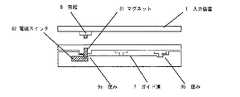
本発明の第三の実施の形態について図8を用いて説明する。図8において81は突起8の中または近傍に設けたマグネットであり、82はベースユニット2側の窪み9a近傍に設けた電磁スイッチである。これ以外の部分については実施の形態1と同じなので省略する。
【0028】
液晶ディスプレイ3が開いた状態一杯まで入力装置1を回転させると、マグネット81と電磁スイッチ82が、入力装置1の筐体およびベースユニット2の筐体を挟み隣接することになる。これにより電磁スイッチ82が導通するため携帯型情報処理装置の電源を投入し、携帯型情報処理装置が稼動状態となる。
【0029】
また、稼動状態から入力装置1を回転させ液晶ディスプレイ3を閉じた状態にする。突起部8は窪み9aからガイド溝7に沿って窪み9bに移動するため、マグネット81も電磁スイッチ82から遠ざかるため、電磁スイッチ82が遮断状態になる。電磁スイッチ82の遮断を受けて携帯型情報処理装置の電源をオフにする。電源の切り方としては、電子回路への電力供給をカットしても良いし、電磁スイッチ82の信号により作業中のデータをフラッシュメモリーなどの不揮発性メモリーに格納したのち電子回路の電源を遮断してもよい。
【0030】
入力装置1により液晶ディスプレイ3を閉じた状態で使用することはなく、閉じた状態では電子回路の電源を遮断し消費電力を節約することにより電池の寿命を大きく伸ばすことができる。
【0031】
(実施の形態4)
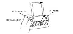
本発明の第四の実施の形態について図9および図10を用いて説明する。図9において91は入力装置であり92はジョイスティックである。その他の構成については実施の形態1と同様なので省略する。ポインティングデバイスとしてはXY方向に倒れる棒状または板状のジョイスティック92を回転軸の上または近傍に設けるものとする。図9に示すように携帯型情報処理装置を左手で保持するとちょうど親指の位置にジョイスティック92が位置するため、左手の親指で携帯型情報処理装置を保持しながらポインティングデバイスの操作が可能となる。さらに、右手を使って文字入力が可能なのでポインティングデバイスの操作と文字入力の操作を同時に行うことが可能となる。
【0032】
なお、ジョイスティック92の位置をほぼ左右対称の位置(図9では右側になる)にして、右手でポインティングデバイスの操作を行い左手で文字入力を行っても同様の効果が得られる。
【0033】
図10はタッチパネルを備えた場合の正面図であり、液晶ディスプレイ3の前面にタッチパネル93が位置する。携帯型情報処理装置を左手で保持しながら右手でペン94を用いて入力を行うことによりポインティング操作ができる。
【0034】
図11は図10における入力装置101の断面図であり、入力装置101の表面は継ぎ目のないエラストマカバー102で覆われるとともに、エラストマカバー102の面スイッチ103を覆う部分には窪み104を設ける。タッチパネル93の操作は専用のペン94で行うことになるが、この場合はタッチパネル93だけでなく、キーボードに相当する入力装置101もタッチペン94で操作することがある。図11の入力装置の断面図で示すように、タッチペン94で入力装置101を操作すると、ペン先はエラストマカバー102に設けた窪み104に引っかかるため入力のミスが生じにくいものとなる。
【0035】
本発明は、以上説明したように、使用時には露出された縦長形状の液晶ディスプレイに対して入力装置が横長となるため、キー間のピッチを大きく取り易く文字入力の際の誤操作が少なくなるのみならず、この液晶ディスプレイを備えたベースユニットとこれとは別体の入力装置を回転軸で連結された形式の装置であっても、使用時には液晶ディスプレイの左右の中心線と入力装置の左右の中心線がほぼ重なった位置になるようにしたため、縦長形状の液晶ディスプレイが横長形状の入力装置の中心正面に位置し、このため、表示が見やすく、かつ、操作性に優れるという効果を有する。
そして、非使用時には入力装置により液晶ディスプレイが覆い隠されるため、液晶ディスプレイの表面を圧力や衝撃から保護するという有益なものである。
さらに、ベースユニットに設けられた円弧状のガイド溝の両端に設けられた第1の窪みおよび第2の窪みと、入力装置に設けられ、前記ガイド溝内の移動により第1の窪みおよび第2の窪みに嵌合可能な突起からなる第一の保持手段および第二の保持手段により、ベースユニットとともに液晶ディスプレイが覆い隠された非使用時と液晶ディスプレイが露出されて液晶ディスプレイの左右の中心線と入力装置の左右の中心線がほぼ重なった使用時の状態が確実に規制され、これらの状態が安定するものである。
【図面の簡単な説明】
【図1】 (a)本発明の一実施の形態における液晶ディスプレイを閉じた状態の正面図
(b)本発明の一実施の形態における液晶ディスプレイを開いた状態の正面図
【図2】 図1(a)におけるA−A断面図
【図3】 液晶ディスプレイの開閉の途中の状態を示す斜視図
【図4】 液晶ディスプレイを開いて使用している状態を示す斜視図
【図5】 (a)回転角を規制するための構造を示す斜視図
(b)回転角を規制するための構造を示す断面図
【図6】 同回転角を規制するための他の構造を示す斜視図
【図7】 本発明の第二の実施の形態における入力装置の構造を示す断面図
【図8】 本発明の第三の実施の形態における液晶ディスプレイの開閉を検知するための構造を示す断面図
【図9】 本発明の第四の実施の形態における入力装置にポインティングデバイスを備えた場合の正面図
【図10】 本発明の第四の実施の形態におけるタッチパネルを備えた場合の正面図
【図11】 本発明の第四の実施の形態における入力装置の構造を示す断面図
【符号の説明】
1、71、91、101 入力装置
2、72 ベースユニット
3 液晶ディスプレイ
4 回転軸
7 ガイド溝
8 突起
9a、9b 窪み
75、103 面スイッチ
76、102 エラストマカバー
81 マグネット
82 電磁スイッチ
92 ジョイスティック
93 タッチパネル
104 窪み(入力装置上面)[0001]
BACKGROUND OF THE INVENTION
The present invention relates to a portable information terminal, a so-called PDA (Personal Digital Assistance), having a vertical display device that is generally sized to be carried in a pocket.
[0002]
[Prior art]
Among conventional portable information processing apparatuses, a device called a PDA (Personal Digital Assistant) having a vertically long liquid crystal display that is large enough to be placed in a breast pocket has become widespread. In these devices, since it is not possible to have a sufficiently large keyboard, it is common to perform not only the function of the pointing device but also the character input with a pen. However, since character input pads occupy a part of the screen for inputting characters using a pen, the display portion of a small screen is smaller than that of a personal computer, so the amount of information that can be displayed at one time is small. It was hard to see. To solve this,For example, thetable radical 113 min some Separately provided with a key switch for a key input, but there is a problem that it is easy press up key pitch adjacent narrow between keys simultaneously.
[0003]
[Problems to be solved by the invention]
In such a portable information processing device, since the display device is a vertical type, theentire display device is vertically long. On the other hand, the input device is horizontally long so that a key switch for key input has a certain key pitch. It is desirable to be. Alternatively, the longitudinal direction of the liquid crystal display resulting inTsu shorter and when the horizontal thewhole to the width of the input device.
[0004]
The present invention has been made to solve the above-described problems, and provides a portable information processing device that is excellent in portability byrotating the input device when carried and has excellent operability for key input. Objective.
[0005]
[Means for Solving the Problems]
In order to achieve this object, the portable information processing apparatus of the present invention is generally a vertical liquid crystal display and a liquid crystal display of a casing serving as a base unit storing main electronic circuits such as a battery and a CPU (central processing unit). An input deviceis rotatably connected to the lower left side through a rotating shaft. The base unit aboutthe axis of rotation and the input device is connected as an angle variable. In addition, when the input device is rotated so as to overlap the liquid crystal display, the size and shape are set such that the input device completely covers the opening for exposing the liquid crystal display. When carrying the portable information processing apparatus of the present invention is such thatmore liquid crystal display is covered by the input device.
[0006]
In a state where the liquid crystal display portion of the base unit is exposed,and position input device in front of the liquid crystal displayis turned left and right horizontally, and the center lineof the left and right of the center line and the input deviceof the right and left liquid crystal display substantially coincide It shall be stable at the position where As a result, the key input operation can be easily performed while holding the input device with both hands.
[0007]
By covering the front surface of the keyboard with a flexible material such as an elastomer and a seamless integrated cover, it is possible to realize waterproofness while enabling key operation.
[0008]
Thereby, it is possible to realize a portable information processing apparatus that is excellent in portability and that allows easy key input operation.
[0009]
DETAILED DESCRIPTION OF THE INVENTION
The present invention relates to a base unit having at least a liquid crystal display and a rotation axis in a direction perpendicular to the liquid crystal display, and an input coupled to the base unit via the rotation axis that is wider than an opening of the liquid crystal display. The liquid crystal display is not exposed when the input device is rotated about the rotation axis and rotated toward the liquid crystal display, and the liquid crystal display is completely rotated when rotated in the opposite direction. The portable information processing device is characterized in that the input device is rotated so as to be exposed, and has an effect of facilitating character input during use while improving portability during storage.
Furthermore, the state where the input device is rotated to cover the base unit and the liquid crystal display, and the state where the input device is rotated in the opposite direction to completely expose the liquid crystal display are displayed at both ends of the arc guide groove of the base unit. The first depression and the second depression provided and the input device are respectively regulated by protrusions that can be fitted into the first depression and the second depression at both ends of the guide groove by movement in the guide groove. Is stable.
[0010]
In the present invention, the rotation axis is positioned on the lower left side of the liquid crystal display, the input device rotates around the rotation axis, and the liquid crystal display is opened, and theleft and right center lines of the liquid crystal display and the input The portable information processing device is characterized in that theleft and right center lines of the device are substantially equal, and has an effect of excellent operability because the input device and the liquid crystal display face the front when in use.
[0011]
The present invention also includes a detection unit that detects the state in which the liquid crystal display is completely exposed by rotating the input device in a direction in which the liquid crystal display is exposed, and when the detection unit detects exposure, the power is turned on. The portable information processing apparatus is characterized in that the power supply is cut off when it is detected that the detection unit is not exposed, and the power supply is cut off automatically when not in use. It has the effect of preventing the amount from being lost.
[0012]
Furthermore, the present invention provides a sealed structure in which both the base unit and the input device do not have an opening in a portion excluding the rotating shaft, and the detection unit is a magnet switch, and both the base unit and the input device are waterproof. Since the portable information processing device is characterized by being easily waterproofed and can be easily realized, the portable information processing device can be used even in the rainy environment such as outdoors.
[0013]
Further, the present invention, the input device in addition to the switch for inputting characters and symbols,mobile type information processing apparatusyou comprising the pointing device such as a touch pad or XY direction of the joystick It has the effect that character input and pointing operation can be performed simultaneously.
Hereinafter, embodiments of the present invention will be described with reference to FIGS.
[0014]
(Embodiment 1)
FIG. 1 is a front view showing an overview of a portable information processing device according to an embodiment of the present invention. FIG. 1A is a front view when a liquid crystal display is closed by rotating an input device, and FIG. It is a front view at the time of rotating a device and opening a liquid crystal display. FIG. 2 is a cross-sectional view taken along line AA in FIG.
[0015]
In FIG. 1, 1 is an input device for inputting characters and symbols, and 2 is a base unit which stores electronic circuits such as a CPU and a memory, and a battery for operating the electronic circuits. A liquid crystal display 3 for display is provided on the front surface of the base unit 2. The input device 1 and the base unit 2 are coupled to each other through a rotating shaft 4 so that the angle is variable.
[0016]
Switches 5 corresponding to characters and symbols are arranged in a matrix on the front surface of the input device 1, and symbols (not shown) of characters or symbols corresponding to the switches 5 are displayed on the front surface of the switch 5. Characters and symbols are input by touching the upper surface of the switch 5 with the tip of a finger or a pen. The character arrangement conforms to a general keyboard arrangement (for example, QWERTY arrangement). Since the switch 5 may be touched with a finger, if the distance between the adjacent switches 5 is too narrow, when the switch 5 is pressed, the adjacent switches 5 are pushed, so the gap should be as wide as possible. . In the case of the QWERTY arrangement, since the number of keys arranged in the horizontal direction is larger than that in the vertical direction, a horizontally long shape is desirable. Therefore, it is a horizontally long shape.
[0017]
The base unit 2 is equipped with a liquid crystal display 3. The width of the liquid crystal display 3 is preferably narrower than the width of the base unit 2 by the circuit of the liquid crystal display 3 and as wide as possible. The shape is preferably a square or a slightly vertically long shape. If the width of the left and right if you want to display text, such as incoming e-mail is wide, because the movement of the line of sight increases in the portion of the new line, easilyseen Ri due to be displayed more in the vertical direction by the liquid crystal of the portrait. For this reason, a vertically long liquid crystaldisplay is used in the portable information processing apparatus of the present invention.
[0018]
When the portable information processing device is not used, the input device 1 is rotated around the rotation shaft 4 so that the input device 1 covers the base unit 2 as shown in the AA sectional view of FIG. To do. Since the input device 1 has a horizontally long shape, the input device 1 can have a shape that exactly matches the vertically long base unit 2. In this state, the liquid crystal display 3 is covered with the input device 1. When carrying in a bag or in a pocket, the input device 1 is in a position to protect the liquid crystal display 3, so that the liquid crystal display 3 can be prevented from being damaged by a mechanical shock.
[0019]
Next, the input device 1 is rotated around the rotation shaft 4 to expose the liquid crystal display 3. Since the rotation axis is provided in front of the liquid crystal display 3, theinput device 1 is positioned in front of the liquid crystal display 3, and the left and right center lines of the liquid crystal display 3 and the left and right center lines of the input device 1 substantially overlap. Become a relationship. FIG.4 shows a state in which the liquid crystal display 3 is opened and key input is performed from the input device 1. When the input is performed while holding the portable information processing apparatus with both the left and right hands, the liquid crystal display 3 is located justin front of thewhole, so that it is easy to see and excellent in operability.
[0020]
FIG. 3 shows a state where the input device 1 is opened and closed while holding the portable information processing device with one hand of the left hand. Since this embodiment is small in size, it can be opened and closed with one hand as shown in the figure. In the opened state as shown in FIG. 4, the user can operate while viewing the screen.
[0021]
The adjustment of the rotation shaft 4 and the rotation angle will be described. In the present invention, the input device 1 can be rotated by 90 °, and is used in a state where the liquid crystal display 3 is fully opened or completely closed. Moreover, since the input device 1 does not need to rotate 90 degrees or more, the method for regulating the rotation angle will be described. 5A and 5B are views for explaining a structure for regulating the rotation angle, where FIG. 5A is a perspective view and FIG. 5B is a cross-sectional view of a groove portion. In FIG. 5, 7 isa guide grooveprovided in the base unit 2 , 9a is a recess located at one end of the guide groove, and 9b is a recess located at the other end of the guide groove. A protrusion 8 that fits into the guide groove 7 is provided on the back surface of the input device 1.
[0022]
The guide groove 7 is a 90 ° arc centered on the rotating shaft 4, and the guide groove is shallower than the height of the protrusion 8. In addition, depressions 9a and 9b are provided at both ends of the guide groove 7, and the depths of the depressions 9a and 9b and the height of the protrusions 8 are equal. In a state where the liquid crystal display 3 is closed by the input device 1, the protrusion 8 is fitted in a recess 9 b at one end of the guide groove 7. In this state, the tip of the protrusion 8 fits into the recess 9b, so that it does not move with a little force, and the liquid crystal display 3is stable in the closed state. When a force is applied to the left side of the input device 1 in this state, the protrusion 8 moves over the recess 9b and moves through the guide groove 7. At this time, since the height of the protrusion 8 is larger than the depth of the guide groove 7, the input device 1 is slightly lifted. Thereafter, when rotated 90 °, the protrusion 8 is fitted into the groove 9a located at the other end of the guide groove 7, and the position is stabilized. With the above configuration, the input device 1 can be used stably with the liquid crystal display 3 opened or closed.
[0023]
FIG. 6 shows another method for regulating the rotation angle. FIG. 6 is a perspective view showing the periphery of the rotating shaft 4 on the base unit 2 side. The rotating shaft 4 is provided with a blade-like protrusion, and the rotation angle of the blade is regulated by the two rod-like protrusions. A wiring (not shown) connecting the input device 1 and the electronic circuit stored in the base unit 2 passes through the center or the periphery of the rotation shaft. In this way, the rotation angle of the input device 1 is restricted to 90 °. By doing so, it is possible to prevent the wiring from being twisted.
[0024]
(Embodiment 2)
The second embodiment of the portable information processing apparatus of the present invention will be described in detail. FIG. 7 is a cross-sectional view of the input device according to the second embodiment of the present invention. In FIG. 7, reference numeral 71 denotes an input device, and reference numeral 75 denotes a sheet-like surface switch which is arranged in a matrix and detects pressing, and is called a so-called membrane. An outer cover of the elastomer cover 76 is provided so as to cover the upper surface of the surface switch 75. On the surface of the elastomer cover 76 at a position corresponding to each switch of the surface switch 75, a symbol display (not shown) of characters or symbols indicating the switches is printed. Further, the elastomer cover 76 has a shape that extends not only to the top surface but also to the side surface or back surface of the input device 71. Since the structure on the base unit side and the rotation method of the input device 71 are the same as those in the first embodiment, the description thereof is omitted.
[0025]
According to the present embodiment, since the surface of the input device 71 is covered with a seamless and flexible material, it is possible to prevent water droplets from entering. Further, when the mobile phone is carried, the input device 71 covers the surface of the liquid crystal display 3 and the surface of the input device 71 is covered with an elastomer cover 76, so that the liquid crystal display 3 is damaged even when subjected to a mechanical shock due to dropping or the like. Risk can be greatly reduced and damage due to careless handling when carrying can be prevented.
[0026]
Furthermore, the waterproof performance can be further improved by the input device 71 and the base unit 2 exchanging data via the wireless communication unit. In this case, since the input device 71 and the base unit 2 are used close to each other, it is possible to communicate with weak power using radio waves or infrared rays.
[0027]
(Embodiment 3)
A third embodiment of the present invention will be described with reference to FIG. In FIG. 8, 81 is a magnet provided in or near the protrusion 8, and 82 is an electromagnetic switch provided in the vicinity of the recess 9 a on the base unit 2 side. Since other parts are the same as those of the first embodiment, they are omitted.
[0028]
When the input device 1 is rotated until the liquid crystal display 3 is fully opened, the magnet 81 and the electromagnetic switch 82 are adjacent to each other with the housing of the input device 1 and the housing of the base unit 2 interposed therebetween. As a result, the electromagnetic switch 82 is turned on, so that the portable information processing apparatus is turned on, and the portable information processing apparatus enters an operating state.
[0029]
Further, the input device 1 is rotated from the operating state to close the liquid crystal display 3. Since the protrusion 8 moves from the depression 9a to the depression 9b along the guide groove 7, the magnet 81 also moves away from the electromagnetic switch 82, so that the electromagnetic switch 82 is cut off. When the electromagnetic switch 82 is cut off, the portable information processing apparatus is turned off. The power can be turned off by cutting off the power supply to the electronic circuit, or by storing the data being worked on in a non-volatile memory such as a flash memory in accordance with the signal from the electromagnetic switch 82 and then turning off the power to the electronic circuit. May be.
[0030]
The liquid crystal display 3 is not used in the closed state by the input device 1, and in the closed state, the battery life can be greatly extended by cutting off the power supply of the electronic circuit to save power consumption.
[0031]
(Embodiment 4)
A fourth embodiment of the present invention will be described with reference to FIGS. In FIG. 9, 91 is an input device, and 92 is a joystick. Other configurations are the same as those in the first embodiment, and thus are omitted. As the pointing device, a rod-like or plate-like joystick 92 that falls in the XY directions is provided on or near the rotation axis. As shown in FIG. 9, when the portable information processing apparatus is held with the left hand, the joystick 92 is positioned at the position of the thumb, so that the pointing device can be operated while holding the portable information processing apparatus with the left thumb. Furthermore, since it is possible to input characters using the right hand, it is possible to perform the pointing device operation and the character input operation simultaneously.
[0032]
It is to be noted that the same effect can be obtained by setting the position of the joystick 92 to a substantially symmetrical position (on the right side in FIG. 9), operating the pointing device with the right hand, and inputting characters with the left hand.
[0033]
FIG. 10 is a front view when a touch panel is provided, and a touch panel 93 is located on the front surface of the liquid crystal display 3. A pointing operation can be performed by performing input using the pen 94 with the right hand while holding the portable information processing apparatus with the left hand.
[0034]
FIG. 11 is a cross-sectional view of the input device 101 in FIG. 10. The surface of the input device 101 is covered with a seamless elastomer cover 102, and a recess 104 is provided in a portion of the elastomer cover 102 covering the surface switch 103. The touch panel 93 is operated with the dedicated pen 94. In this case, not only the touch panel 93 but also the input device 101 corresponding to the keyboard may be operated with the touch pen 94. As shown in the cross-sectional view of the input device in FIG. 11, when the input device 101 is operated with the touch pen 94, the pen tip is caught in the depression 104 provided in the elastomer cover 102, and thus an input error is less likely to occur.
[0035]
The present invention, As described above, since the input device is horizontally long with respect to the liquid crystal display of the exposed elongated shape in use, a less erroneous operation at the time of easy text input takes the large pitch between keysRunomi Even if the base unit having the liquid crystal display is connected to a separate input device by a rotating shaft, the right and left center lines of the liquid crystal display and the left and right input devices Since the center lines are substantially overlapped with each other, the vertically long liquid crystal display is positioned in front of the center of the horizontally long input device, so that the display is easy to see and the operability is excellent.
Since the liquid crystal display is covered with the input device when not in use, it is beneficial to protect the surface of the liquid crystal display from pressure and impact.
Furthermore, the first recess and the second recess provided at both ends of the arc-shaped guide groove provided in the base unit, and the input device, the first recess and the second recess provided by the movement in the guide groove. When the liquid crystal display is covered with the base unit and the liquid crystal display is exposed when the liquid crystal display is covered with the base unit by the first holding means and the second holding means that can be fitted in the recesses of the liquid crystal display, the left and right center lines of the liquid crystal display And the state at the time of use in which the left and right center lines of the input device substantially overlap each other is reliably regulated, and these states are stabilized.
[Brief description of the drawings]
1A is a front view of a liquid crystal display according to an embodiment of the present invention when the liquid crystal display is closed. FIG. 1B is a front view of a liquid crystal display according to an embodiment of the present invention when the liquid crystal display is opened. FIG. 3 is a perspective view showing a state in the middle of opening and closing of the liquid crystal display. FIG. 4 is a perspective view showing a state in which the liquid crystal display is opened and used. FIG. 6 is a perspective view showing a structure for regulating the rotation angle. FIG. 6 is a perspective view showing another structure for regulating the rotation angle. Sectional drawing which shows the structure of the input device in 2nd embodiment of this invention. FIG. 8 is sectional drawing which shows the structure for detecting opening and closing of the liquid crystal display in 3rd embodiment of this invention. In the input device in the fourth embodiment of the present invention FIG. 10 is a front view when a touch panel is provided according to the fourth embodiment of the present invention. FIG. 11 is a diagram illustrating a structure of an input device according to the fourth embodiment of the present invention. Sectional view showing [signs]
1, 71, 91, 101 Input device 2, 72 Base unit 3 Liquid crystal display 4 Rotating shaft 7 Guide groove 8 Projection 9a, 9b Recess 75, 103 Surface switch 76, 102 Elastomer cover 81 Magnet 82 Electromagnetic switch 92 Joystick 93 Touch panel 104 Recess (Top of input device)
Claims (1)
Translated fromJapanese前記ベースユニットに備えられ、使用状態が縦長形状に設定された液晶ディスプレイと、
文字や記号の入力を行うスイッチを有し、使用状態が横長形状に設定された入力装置と、
前記ベースユニットと入力装置を回転可能に連結する回転軸と、
前記ベースユニットに対する入力装置の回転角を規制する第一の保持手段および第二の保持手段とを備え、
前記第一の保持手段および第二の保持手段は、前記回転軸を中心として前記ベースユニットに設けられた円弧状のガイド溝の両端に設けられた第1の窪みおよび第2の窪みと、前記入力装置に設けられ、前記ガイド溝内の移動によりそのガイド溝の両端に位置する第1の窪みおよび第2の窪みに嵌合可能な突起からなり、
前記ベースユニットに対して入力装置が前記回転軸を中心に回転されて前記突起と前記第1の窪みからなる第一の保持手段により回転角が規制された状態では、当該入力装置は前記ベースユニットとともに液晶ディスプレイを覆い隠す状態となり、かつ、前記ベースユニットに対して入力装置が回転されてその入力装置が前記突起と前記第2の窪みからなる第二の保持手段により回転角が規制された状態では、ベースユニットに備えられた液晶ディスプレイは露出され、
前記入力装置が前記第二の保持手段により回転角が規制された状態では、前記液晶ディスプレイの左右の中心線と入力装置の左右の中心線がほぼ重なった位置で縦長形状に設定された液晶ディスプレイとベースユニットに対して入力装置が横長形状になるように構成したことを特徴とする入力装置を備えた携帯型情報処理装置。A base unit in which an electronic circuit is stored and the usage state is set to a vertically long shape;
A liquid crystal display provided in the base unit and in which the use state is set to a vertically long shape;
An input device that has a switch for inputting characters and symbols and whose usage state is set to a horizontally long shape;
A rotating shaft rotatably connecting the base unit and the input device;
A first holding means and a second holding means for regulating a rotation angle of the input device with respect to the base unit;
The first holding means and the second holding means include a first depression and a second depression provided at both ends of an arcuate guide groove provided in the base unit with the rotation axis as a center, and It is provided in the input device, and includes a projection that can be fitted into the first recess and the second recess located at both ends of the guide groove by movement in the guide groove,
In a state where the input device isrotated around the rotation axis with respect to the base unitand the rotation angle is regulated by the first holding means including theprotrusion and the first depression , theinput device is the base unit. In addition, theliquid crystal display is covered and the input device is rotated with respect to the base unit, and the rotation angle of the input device is restricted by the second holding means including theprotrusion and the second depression. Then, the liquid crystal display provided in the base unit is exposed,
In a state where the rotation angle of the input device is restricted by the second holding means, a liquid crystal display set in a vertically long shape at a position where the left and right center lines of the liquid crystal display and the left and right center lines of the input device substantially overlap each other. A portable information processing apparatus having an input device, wherein the input device is configured to be horizontally long with respect to the base unit.
Priority Applications (2)
| Application Number | Priority Date | Filing Date | Title |
|---|---|---|---|
| JP2001038051AJP4613427B2 (en) | 2001-02-15 | 2001-02-15 | Portable information processing apparatus having an input device |
| US09/842,651US6477040B2 (en) | 2001-02-15 | 2001-04-27 | Portable information processing device having input unit |
Applications Claiming Priority (1)
| Application Number | Priority Date | Filing Date | Title |
|---|---|---|---|
| JP2001038051AJP4613427B2 (en) | 2001-02-15 | 2001-02-15 | Portable information processing apparatus having an input device |
Publications (2)
| Publication Number | Publication Date |
|---|---|
| JP2002244764A JP2002244764A (en) | 2002-08-30 |
| JP4613427B2true JP4613427B2 (en) | 2011-01-19 |
Family
ID=18901096
Family Applications (1)
| Application Number | Title | Priority Date | Filing Date |
|---|---|---|---|
| JP2001038051AExpired - LifetimeJP4613427B2 (en) | 2001-02-15 | 2001-02-15 | Portable information processing apparatus having an input device |
Country Status (2)
| Country | Link |
|---|---|
| US (1) | US6477040B2 (en) |
| JP (1) | JP4613427B2 (en) |
Families Citing this family (27)
| Publication number | Priority date | Publication date | Assignee | Title |
|---|---|---|---|---|
| JP4084582B2 (en) | 2001-04-27 | 2008-04-30 | 俊司 加藤 | Touch type key input device |
| AU2002360497A1 (en) | 2001-12-06 | 2003-06-23 | Rast Associates, Llc | Expandable and contractible keyboard device |
| US20030132863A1 (en)* | 2001-12-06 | 2003-07-17 | Lahr Roy J. | Articulated, rotatable expandable and contractible keyboard device |
| KR100474678B1 (en)* | 2002-10-24 | 2005-03-10 | 삼성전자주식회사 | Portable communication apparatus with data inputting expansion |
| WO2004049150A2 (en)* | 2002-11-21 | 2004-06-10 | Danger, Inc. | Data processing device with adjuntable display and input devices with multiple orientations |
| JP2004246605A (en)* | 2003-02-13 | 2004-09-02 | Sony Corp | Information processor |
| US7071916B2 (en)* | 2003-09-29 | 2006-07-04 | Danger, Inc. | User input configurations for a data processing device |
| US7636748B2 (en) | 2003-09-29 | 2009-12-22 | Microsoft Corporation | Display configurations for a data processing device |
| US7280346B2 (en)* | 2003-09-29 | 2007-10-09 | Danger, Inc. | Adjustable display for a data processing apparatus |
| TWM249125U (en)* | 2003-11-03 | 2004-11-01 | High Tech Comp Corp | Handheld electronic device |
| EP1600843A1 (en)* | 2004-05-26 | 2005-11-30 | High Tech Computer Corp. | Handheld electronic device with keyboard |
| JP2006019925A (en)* | 2004-06-30 | 2006-01-19 | Sharp Corp | Portable information terminal, opening / closing method thereof, and display method thereof |
| JP4203476B2 (en) | 2005-01-24 | 2009-01-07 | シャープ株式会社 | Portable information device |
| TWI274982B (en)* | 2005-05-06 | 2007-03-01 | Asia Optical Co Inc | Handheld input device having a rotating mechanism |
| JP4749035B2 (en)* | 2005-05-24 | 2011-08-17 | 株式会社小松製作所 | Monitor device |
| KR101299323B1 (en)* | 2005-09-20 | 2013-08-26 | 스가쓰네 고우교 가부시키가이샤 | Mobile device |
| US7809414B2 (en) | 2005-12-14 | 2010-10-05 | Sharp Kabushiki Kaisha | Portable information terminal, opening/closing operation method, and display method |
| CN101309307B (en)* | 2007-05-18 | 2011-06-08 | 深圳富泰宏精密工业有限公司 | Portable electronic device |
| US7549692B2 (en)* | 2007-10-31 | 2009-06-23 | Washington Derron K | Ramp assembly for a vehicle tailgate |
| US7715191B2 (en)* | 2008-04-07 | 2010-05-11 | Research In Motion Limited | Handheld electronic communication device transitionable between compact and expanded configurations |
| JP2009207198A (en)* | 2009-06-16 | 2009-09-10 | Sharp Corp | Personal digital assistant |
| DE102011002024A1 (en)* | 2011-04-13 | 2012-10-18 | Tyco Electronics Amp Gmbh | Charging plug with contactless switching device |
| CN209462415U (en) | 2018-09-07 | 2019-10-01 | Oppo广东移动通信有限公司 | mobile terminal |
| CN113489814B (en)* | 2018-12-10 | 2024-01-05 | Oppo广东移动通信有限公司 | Electronic equipment |
| KR102288129B1 (en)* | 2020-02-06 | 2021-08-10 | 주식회사 토비스 | Button complex structure |
| US20230084154A1 (en)* | 2021-09-13 | 2023-03-16 | Finalmouse LLC | Computer keyboard with a display |
| US11899849B1 (en) | 2022-11-02 | 2024-02-13 | Finalmouse LLC | Computer keyboard with a display |
Family Cites Families (12)
| Publication number | Priority date | Publication date | Assignee | Title |
|---|---|---|---|---|
| JPS6361050U (en)* | 1986-10-13 | 1988-04-22 | ||
| US6141667A (en)* | 1994-07-12 | 2000-10-31 | Duff; Mark Blaise | Waterproofing and increasing portability of a portable computer |
| US6137476A (en)* | 1994-08-25 | 2000-10-24 | International Business Machines Corp. | Data mouse |
| JP3360455B2 (en)* | 1994-12-27 | 2002-12-24 | カシオ計算機株式会社 | Information processing equipment |
| US5548477A (en)* | 1995-01-27 | 1996-08-20 | Khyber Technologies Corporation | Combination keyboard and cover for a handheld computer |
| JPH1055227A (en)* | 1996-08-09 | 1998-02-24 | Sharp Corp | Information processing device |
| US5973915A (en)* | 1996-12-13 | 1999-10-26 | Ncr Corporation | Pivotable display for portable electronic device |
| IL119955A0 (en)* | 1997-01-01 | 1997-04-15 | Advanced Recognition Tech | An instruction and/or identification input unit |
| JP4243344B2 (en)* | 1997-05-23 | 2009-03-25 | 株式会社Access | Mobile communication equipment |
| US6137479A (en)* | 1997-12-05 | 2000-10-24 | Timex Corporation | Programmable computer pointing device |
| US6052624A (en)* | 1999-01-07 | 2000-04-18 | Advanced Bionics Corporation | Directional programming for implantable electrode arrays |
| US6109039A (en)* | 1999-03-24 | 2000-08-29 | International Business Machines Corporation | Heat transfer in electronic apparatus |
- 2001
- 2001-02-15JPJP2001038051Apatent/JP4613427B2/ennot_activeExpired - Lifetime
- 2001-04-27USUS09/842,651patent/US6477040B2/ennot_activeExpired - Lifetime
Also Published As
| Publication number | Publication date |
|---|---|
| JP2002244764A (en) | 2002-08-30 |
| US20020109965A1 (en) | 2002-08-15 |
| US6477040B2 (en) | 2002-11-05 |
Similar Documents
| Publication | Publication Date | Title |
|---|---|---|
| JP4613427B2 (en) | Portable information processing apparatus having an input device | |
| CN205068296U (en) | Electronic equipment and portable electronic equipment | |
| US20050091431A1 (en) | Portable communication devices | |
| US7447527B2 (en) | Handheld electronic data processing device with multiple operation modes for different functions | |
| US7336481B2 (en) | Information processing apparatus having switch for inputting key data | |
| US20050125570A1 (en) | Portable communication devices | |
| CN101930865B (en) | Electronic device with rotary keyboard | |
| KR20050026989A (en) | Portable computing device with foldable keyboard | |
| CA2270213A1 (en) | Hand-held computer and communications apparatus | |
| JP2008269061A (en) | Electronic apparatus | |
| JP3993986B2 (en) | Input device and information processing device | |
| JP2013089257A (en) | Portable electronic equipment | |
| US20030197745A1 (en) | Portable computing device keyboard | |
| JP2003044199A (en) | Portable electronic apparatus | |
| BRPI0901285B1 (en) | device for connecting a trackball set and portable electronic device | |
| CN216052838U (en) | Tablet personal computer protective shell convenient to hold by hand | |
| US20140253456A1 (en) | Electronic device including keypad with keys having a ridged surface profile | |
| CN101617283A (en) | Portable terminal and operation method of portable terminal | |
| CN208766630U (en) | It is a kind of can be with the portable equipment of turnover screen | |
| JP4668932B2 (en) | Mobile terminal device | |
| JP2003345497A (en) | Electronic apparatus | |
| US20090195509A1 (en) | Narrow angular keyboard for a handheld mobile communication device | |
| KR20090076021A (en) | Mobile devices | |
| EP2088496A1 (en) | Narrow angular keyboard for a handheld mobile communication device | |
| JP2003167665A (en) | Input device |
Legal Events
| Date | Code | Title | Description |
|---|---|---|---|
| A621 | Written request for application examination | Free format text:JAPANESE INTERMEDIATE CODE: A621 Effective date:20070510 | |
| RD01 | Notification of change of attorney | Free format text:JAPANESE INTERMEDIATE CODE: A7421 Effective date:20070613 | |
| RD01 | Notification of change of attorney | Free format text:JAPANESE INTERMEDIATE CODE: A7421 Effective date:20091119 | |
| A977 | Report on retrieval | Free format text:JAPANESE INTERMEDIATE CODE: A971007 Effective date:20100121 | |
| A131 | Notification of reasons for refusal | Free format text:JAPANESE INTERMEDIATE CODE: A131 Effective date:20100126 | |
| A521 | Request for written amendment filed | Free format text:JAPANESE INTERMEDIATE CODE: A523 Effective date:20100302 | |
| A131 | Notification of reasons for refusal | Free format text:JAPANESE INTERMEDIATE CODE: A131 Effective date:20100720 | |
| A521 | Request for written amendment filed | Free format text:JAPANESE INTERMEDIATE CODE: A523 Effective date:20100901 | |
| TRDD | Decision of grant or rejection written | ||
| A01 | Written decision to grant a patent or to grant a registration (utility model) | Free format text:JAPANESE INTERMEDIATE CODE: A01 Effective date:20100921 | |
| A01 | Written decision to grant a patent or to grant a registration (utility model) | Free format text:JAPANESE INTERMEDIATE CODE: A01 | |
| A61 | First payment of annual fees (during grant procedure) | Free format text:JAPANESE INTERMEDIATE CODE: A61 Effective date:20101004 | |
| R151 | Written notification of patent or utility model registration | Ref document number:4613427 Country of ref document:JP Free format text:JAPANESE INTERMEDIATE CODE: R151 | |
| FPAY | Renewal fee payment (event date is renewal date of database) | Free format text:PAYMENT UNTIL: 20131029 Year of fee payment:3 | |
| S111 | Request for change of ownership or part of ownership | Free format text:JAPANESE INTERMEDIATE CODE: R313113 | |
| R350 | Written notification of registration of transfer | Free format text:JAPANESE INTERMEDIATE CODE: R350 | |
| S111 | Request for change of ownership or part of ownership | Free format text:JAPANESE INTERMEDIATE CODE: R313113 | |
| R350 | Written notification of registration of transfer | Free format text:JAPANESE INTERMEDIATE CODE: R350 | |
| EXPY | Cancellation because of completion of term |