JP4612679B2 - Surveillance system workstation - Google Patents
Surveillance system workstationDownload PDFInfo
- Publication number
- JP4612679B2 JP4612679B2JP2007515308AJP2007515308AJP4612679B2JP 4612679 B2JP4612679 B2JP 4612679B2JP 2007515308 AJP2007515308 AJP 2007515308AJP 2007515308 AJP2007515308 AJP 2007515308AJP 4612679 B2JP4612679 B2JP 4612679B2
- Authority
- JP
- Japan
- Prior art keywords
- control unit
- user input
- input device
- display
- icon
- Prior art date
- Legal status (The legal status is an assumption and is not a legal conclusion. Google has not performed a legal analysis and makes no representation as to the accuracy of the status listed.)
- Expired - Fee Related
Links
Images


Classifications
- G—PHYSICS
- G08—SIGNALLING
- G08B—SIGNALLING OR CALLING SYSTEMS; ORDER TELEGRAPHS; ALARM SYSTEMS
- G08B25/00—Alarm systems in which the location of the alarm condition is signalled to a central station, e.g. fire or police telegraphic systems
- G08B25/14—Central alarm receiver or annunciator arrangements
- G—PHYSICS
- G06—COMPUTING OR CALCULATING; COUNTING
- G06F—ELECTRIC DIGITAL DATA PROCESSING
- G06F3/00—Input arrangements for transferring data to be processed into a form capable of being handled by the computer; Output arrangements for transferring data from processing unit to output unit, e.g. interface arrangements
- G06F3/01—Input arrangements or combined input and output arrangements for interaction between user and computer
- G06F3/02—Input arrangements using manually operated switches, e.g. using keyboards or dials
- G06F3/0202—Constructional details or processes of manufacture of the input device
- G—PHYSICS
- G06—COMPUTING OR CALCULATING; COUNTING
- G06F—ELECTRIC DIGITAL DATA PROCESSING
- G06F3/00—Input arrangements for transferring data to be processed into a form capable of being handled by the computer; Output arrangements for transferring data from processing unit to output unit, e.g. interface arrangements
- G06F3/01—Input arrangements or combined input and output arrangements for interaction between user and computer
- G06F3/048—Interaction techniques based on graphical user interfaces [GUI]
- G06F3/0481—Interaction techniques based on graphical user interfaces [GUI] based on specific properties of the displayed interaction object or a metaphor-based environment, e.g. interaction with desktop elements like windows or icons, or assisted by a cursor's changing behaviour or appearance
- G06F3/04817—Interaction techniques based on graphical user interfaces [GUI] based on specific properties of the displayed interaction object or a metaphor-based environment, e.g. interaction with desktop elements like windows or icons, or assisted by a cursor's changing behaviour or appearance using icons
- G—PHYSICS
- G06—COMPUTING OR CALCULATING; COUNTING
- G06F—ELECTRIC DIGITAL DATA PROCESSING
- G06F3/00—Input arrangements for transferring data to be processed into a form capable of being handled by the computer; Output arrangements for transferring data from processing unit to output unit, e.g. interface arrangements
- G06F3/01—Input arrangements or combined input and output arrangements for interaction between user and computer
- G06F3/048—Interaction techniques based on graphical user interfaces [GUI]
- G06F3/0487—Interaction techniques based on graphical user interfaces [GUI] using specific features provided by the input device, e.g. functions controlled by the rotation of a mouse with dual sensing arrangements, or of the nature of the input device, e.g. tap gestures based on pressure sensed by a digitiser
- G06F3/0489—Interaction techniques based on graphical user interfaces [GUI] using specific features provided by the input device, e.g. functions controlled by the rotation of a mouse with dual sensing arrangements, or of the nature of the input device, e.g. tap gestures based on pressure sensed by a digitiser using dedicated keyboard keys or combinations thereof
Landscapes
- Engineering & Computer Science (AREA)
- General Engineering & Computer Science (AREA)
- Theoretical Computer Science (AREA)
- Physics & Mathematics (AREA)
- General Physics & Mathematics (AREA)
- Human Computer Interaction (AREA)
- Business, Economics & Management (AREA)
- Emergency Management (AREA)
- User Interface Of Digital Computer (AREA)
- Alarm Systems (AREA)
- Input From Keyboards Or The Like (AREA)
- Selective Calling Equipment (AREA)
Description
Translated fromJapanese発明の背景
この発明は監視システムに関し、特に監視システムに使用するワークステーションに関する。ここに使用される監視システムは、ビル管理、警備システムを含むものである。BACKGROUND OF THE INVENTION 1. Field of the Invention The present invention relates to a monitoring system, and more particularly to a workstation used in the monitoring system. The monitoring system used here includes building management and security systems.
従来の監視システムワークステーションは、コントローラのキーボードの幅広いファンクションキーの記憶をユーザに要求し、確実に望まれる機能を操作する事はユーザにとっては扱いが難しいものであった。さらに、これらのキーは特殊な機能を有しており、それはデイスプレイの変更をユーザインターフェイスとして変更ができず、そのため機能付加の可能性が遂行できないものである。さらに、従来のシステムは、モニタに現れるユーザインターフェイスに対しユーザ入力装置で得られるべき操作に関連したユーザ手順を提供しないからである。したがって、これらは監視システムで使用するための改善されたワークステーションが必要とされており、それはユーザへのよりゆったりした使用感が備えられたものである。 Conventional surveillance system workstations require the user to memorize a wide range of function keys on the controller keyboard, making it difficult for the user to reliably operate the desired functions. In addition, these keys have special functions, which cannot be changed by changing the display as a user interface, so that the possibility of adding functions cannot be performed. Furthermore, conventional systems do not provide user procedures related to the operations to be obtained with the user input device for the user interface appearing on the monitor. Thus, there is a need for an improved workstation for use in a surveillance system, which provides a more relaxed user experience.
発明の概要
この発明によれば、それはディスプレイ、ユーザ入力装置そしてディスプレイとユーザ入力装置間の通信をなすコントロールユニットにて構成する監視システム用ワークステーションを提供するものである。ユーザ入力装置は、複数のキーと複数のカラーにてそのキーを照明する光源を有している。コントロールユニットはディスプレイ上にイメージを生成させるもので、そのディスプレイは複数の異なるカラー化アイコンを有し、当該複数のアイコンの各々は、コントロールユニットで遂行される機能をシンボル化する。コントロールユニットは、ユーザ入力装置にコントロール信号を生成するもので、それはディスプレイ上のイメージ内のアイコンカラーに対応するカラーでユーザ入力装置内の複数のキーの光源を点灯させる信号である。コントロールユニットは、異なるカラーにした複数のアイコンから特定のアイコンに対応するコントロール機能を成すもので、それはユーザが特定のアイコンのカラーに相当するカラーを有した特定のキーによるキーを起動したときである。SUMMARY OF THE INVENTION According to the present invention, it provides a surveillance system workstation comprising a display, a user input device and a control unit for communication between the display and the user input device. The user input device has a light source that illuminates the key with a plurality of keys and a plurality of colors. Control unit intended to produce an image on a display, the displaymayhave a different color of the icon ofseveral, each of the plurality of iconssymbolizing the function performed by the control unit. The control unit generates a control signal for the user input device, and is a signal for lighting the light sources of a plurality of keys in the user input device with a color corresponding to the icon color in the image on the display. The control unit forms a control function corresponding to a specific icon from a plurality of icons of different colors when the user activates a key with a specific key having a color corresponding to the color of the specific icon. is there.
この発明によれば、それはディスプレイ、ユーザ入力装置そしてディスプレイとユーザ入力装置間の通信をなすコントロールユニットにて構成する監視システム用ワークステーションをさらに提供するものである。ユーザ入力装置は複数のキーとキーを照明する光源を有している。コントロールユニットはディスプレイ上にイメージを生成させ、そのディスプレイはコントロールユニットにより遂行される機能をシンボル化した複数の異なったアイコンを有している。コントロールユニットはアラーム状態が起こっているときにコントロール信号を生成し、スクリーンの明滅でアラーム状態のアイコン表示を起動させ、かつユーザ入力装置内の光源を起動させる信号を生成し、アラーム状態を解除するためにユーザ入力が要求されるキー内照明を明滅させる。According to the invention, it further provides a monitoring system workstation comprising a display, a user input device and a control unit for communication between the display and the user input device. The user input device has a plurality of keys and a light source that illuminates the keys. The control unit generates an image on the display, which has a plurality of different icons symbolizing the functions performed by the control unit. Controlunit generates a control signal when that occurredalarmcondition,generates a signal to activate the icon display of alarm conditions by flashing thescan cleanactivates the light source orthe rainy season over The input in theapparatus, Blinksin- key lightingthat requires user input toclear the alarm condition.
この発明の他の優位性および応用は、発明の好ましい態様についてした詳細な説明にて明らかになる。 Other advantages and applications of the present invention will become apparent in the detailed description of the preferred embodiments of the invention.
この発明のより完全な理解と付随した優位性および特徴は、次の詳細な説明、添付の図面を参照することでより容易に理解される。 A more complete understanding of the present invention and the attendant advantages and features will be more readily understood by reference to the following detailed description and accompanying drawings.
発明の詳細な説明
図1について説明すると、警備システム10はこの発明によるユーザワークステーション12を付加して示してある。ユーザワークステーション12は、入力装置14を備え、コントロールユニット16およびディスプレイ18がネットワーク20にて接続されている。それは、近接ネットワーク、ローカルエリアネットワークあるいはインターネットのような広域ネットワークである。ユーザ入力装置14とディスプレイ18は近接して位置しており、そうすることでユーザがユーザ入力装置14を操作する間、ディスプレイ18のイメージを見ることができるようになっている。一方、マイクロプロセッサー、メモリーおよびプログラムインストラクションを備えたコントロールユニット16は、監視システム10内のいずれかに位置させることができる。コントロールユニット16と組合せたユーザ入力装置14からの入力は、カメラ22、24およびビデオストレージ26の動作を既に知られた技術にてコントロールする。DETAILED DESCRIPTION OF THE INVENTION Referring to FIG. 1, a
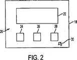
図2において、ディスプレイ18はイメージ20にて示され、それはビデオデータ22および長方形や特殊な形のアイコン24、26そして28を含んでいる。アイコン24、26そして28は、イメージ20内に異なる機能をシンボル化した異なるカラーをもってコントロールユニット16にて表示され、それは例えばカメラの選択である。イメージ20はまたポインタ30を有し、それはアイコン24、26そして28の選択、動作のためにジョイステイック、マウスあるいはキーパッドにて動かすことができる。2, deI
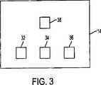
ユーザ入力装置14は、図3、図4にその詳細が示してある。ユーザ入力装置14はキー32、34そして36を有し、それは透明なアクリルあるいは他の適切な素材にて形成してある。赤、グリーンそしてブルーの発光ダイオードのような光源40は、各キー32、34および36の下に位置し、そうすることでコントロールユニット16は、適切なカラーで適切なキーを点灯するユーザ入力装置14にコントロール信号を供給でき、各キー32、34および36のカラーがアイコン24、26そして28のカラーに夫々対応するものとなる。図4は光源がキー32の下にどのように位置しているかの概要を示したもので、光源40がコントロールユニット16からのコントロール信号で起動されているときに適切な発光ダイオードまたはダイオードが起動され、そうすることでキー32はアイコン24のカラーに対応する適切なカラーになる。キー32、34および36のカラーは、アイコン24、26そして28と上記のように同一オーダでも異なっていても良い。ユーザ入力装置14は、さらに既に知られているような技術で幅広いコントロール機能を果たすジョイステイック38を有している。 The
キー32、34および36が起動すると、アイコン24、26そして28で示された対応の機能が働き、図5に示すようにディスプレイ18に新しいイメージ42が現れる。イメージ42はビデオデータ22内に留まるが、新しいアイコン44、46および48はユーザに新しい機能を提供するための表示がされる。図5では三つの新しいアイコンが示されているが、総てのアイコンの変化は必ずしも必要ではない。それは、コントロールユニット16が、押圧されたキーで実施される機能を基に表示される適切なイメージを表すためのコントロール信号を提供するからである。When the
コントロールユニット16はコントロール信号を生成するが、それはアラーム状態が、スクリーン上の明滅でアラーム状態を表すアイコンに生じたときである。さらに、コントロールユニット16は適正なキー内の光源40に明滅を起こさせる信号を生成し、それはユーザがアラーム状態から開放するために押圧が必要なキーに相当するキーである。したがって、ユーザ入力装置14の適正なキーは、それが明滅するのでユーザは速やかに認識できる。さらに、コントロールユニット16は、スクリーン上の明滅アイコンのカラーに相当するカラーにて明滅キーを照明できる。 The
この発明の改変および修正は、発明の範囲から逸脱することなく達成できることが理解される。さらに、発明の範囲は、ここに開示した詳細な態様に制限されるように解釈されるものではなく、また先の開示を考慮して理解される特許請求の範囲によってのみ解釈されるということが理解される。 It will be understood that variations and modifications of the present invention can be achieved without departing from the scope of the invention. Further, it is to be understood that the scope of the invention is not to be construed as limited to the detailed embodiments disclosed herein, but is only construed by the claims that are understood in light of the foregoing disclosure. Understood.
この発明は、先に特に示されかつ述べられてきたことに制限されないということが当業者によって理解されるであろう。加えて、特別な記載がない限り、添付の図面は一定の比率ではないことに注意すべきである。多様な修正、改変はこの発明の概念、範囲を逸脱することなく上記の教示を考慮して可能であり、以下の特許請求の範囲によってのみ制限されるものである。 It will be appreciated by persons skilled in the art that the present invention is not limited to what has been particularly shown and described hereinabove. In addition, it should be noted that the attached drawings are not to scale unless otherwise noted. Various modifications and alterations can be made in light of the above teachings without departing from the spirit or scope of the invention, and are limited only by the following claims.
10:監視システム
12:ユーザワークステーション
14:入力装置
16:コントロールユニット
18:ディスプレイ
20:ネットワーク
30:ポインタ
40:光源10: Monitoring System 12: User Workstation 14: Input device 16: control unit 18: DeI Spray <br/> 20: Network 30: Pointer 40: light source
Claims (10)
Translated fromJapanese前記コントロールユニットは、ユーザが前記ユーザ入力装置上の前記複数の照明されたキーの一つを起動するとき、第二のイメージを前記ディスプレイ上に生成し、前記ディスプレイは複数の異なるカラー化したアイコンを有し、少なくとも幾つかの前記アイコンはディスプレイ上に表示された前のイメージにおける機能とは異なる、前記コントロールユニットにて遂行される機能をシンボル化する、監視システム用ワークステーション。Display, is constituted by a control unit which forms a communication between the user input device and thede-I spray a user input device, said user input device includes a light source for illuminating the keys of a plurality of keys and a plurality of different colors, the the control unit causes the image on the display, the displayhas an icon different colored ofseveral,each of the plurality of iconssymbolizing the function performed by the controlunit, said control unit generates a control signal to the user input device to activate a light source illuminating the plurality of keys in the user input device with a color corresponding to the color of the icon in the image on the deI spray, the control unitis specified Multiple colors that correspond to the icon color A key fromkey遂line control function corresponding to a particular icon fromthe plurality of different colored and icons when a user activates,
Before SL controlunit, when a user activates one of said plurality of illuminated keys on the user input device,generates an second image on thedisplay, wherein the display color of a plurality of different to have icons, at least some ofthe icon is different from the functions in the previous image displayed on the display,symbolizing the function performed by the controlunit, workstation monitoring system.
前記コントロールユニットは、ユーザが前記ディスプレイ上前記イメージ内の前記カラー化したアイコンの一つを起動するとき、第二のイメージを前記ディスプレイ上に生成し、前記ディスプレイは複数の異なるカラー化したアイコンを有し、少なくとも幾つかの前記アイコンはディスプレイ上に表示された前のイメージにおける機能とは異なる、前記コントロールユニットにて遂行される機能をシンボル化する、監視システム用ワークステーション。Display, is constituted by a control unit which forms a communication between the user input device and thede-I spray a user input device, said user input device includes a light source for illuminating the keys of a plurality of keys and a plurality of different colors, the the control unit causes the image on the display, the displayhas an icon different colored ofseveral,each of the plurality of iconssymbolizing the function performed by the controlunit, said control unit generates a control signal to the user input device to activate a light source illuminating the plurality of keys in the user input device with a color corresponding to the color of the icon in the image on the deI spray, the control unitis specified Multiple colors that correspond to the icon color A key fromkey遂line control function corresponding to a particular icon fromthe plurality of different colored and icons when a user activates,
Iconsaid controlunit, when a user activates one of said colorized the icon in the on the displayimage,generates ansecond image on thedisplay, which the display is colored different A workstation fora surveillance system,wherein at least some of the icons symbolize functions performed by the control unit that differ from functions in the previous image displayed on the display.
Applications Claiming Priority (2)
| Application Number | Priority Date | Filing Date | Title |
|---|---|---|---|
| US10/853,010US7385590B2 (en) | 2004-05-25 | 2004-05-25 | Surveillance system workstation |
| PCT/US2005/018397WO2005116980A2 (en) | 2004-05-25 | 2005-05-25 | Surveillance system workstation |
Publications (2)
| Publication Number | Publication Date |
|---|---|
| JP2008500641A JP2008500641A (en) | 2008-01-10 |
| JP4612679B2true JP4612679B2 (en) | 2011-01-12 |
Family
ID=35451542
Family Applications (1)
| Application Number | Title | Priority Date | Filing Date |
|---|---|---|---|
| JP2007515308AExpired - Fee RelatedJP4612679B2 (en) | 2004-05-25 | 2005-05-25 | Surveillance system workstation |
Country Status (7)
| Country | Link |
|---|---|
| US (1) | US7385590B2 (en) |
| EP (1) | EP1754216B1 (en) |
| JP (1) | JP4612679B2 (en) |
| CN (2) | CN103647951A (en) |
| AU (1) | AU2005248852B2 (en) |
| ES (1) | ES2525696T3 (en) |
| WO (1) | WO2005116980A2 (en) |
Families Citing this family (8)
| Publication number | Priority date | Publication date | Assignee | Title |
|---|---|---|---|---|
| US7385590B2 (en)* | 2004-05-25 | 2008-06-10 | Pelco, Inc. | Surveillance system workstation |
| JP4063795B2 (en)* | 2004-06-24 | 2008-03-19 | Necディスプレイソリューションズ株式会社 | Image display system |
| US7956890B2 (en)* | 2004-09-17 | 2011-06-07 | Proximex Corporation | Adaptive multi-modal integrated biometric identification detection and surveillance systems |
| US7546555B2 (en)* | 2006-02-24 | 2009-06-09 | Sony Ericsson Mobile Communications Ab | Method and apparatus for matching a control with an icon |
| US9544563B1 (en) | 2007-03-23 | 2017-01-10 | Proximex Corporation | Multi-video navigation system |
| US7777783B1 (en) | 2007-03-23 | 2010-08-17 | Proximex Corporation | Multi-video navigation |
| CN106921377B (en)* | 2015-12-24 | 2020-06-02 | 小米科技有限责任公司 | Touch key module, key icon display method and device |
| CN106328569B (en)* | 2016-11-07 | 2021-04-09 | 北京七星华创电子股份有限公司 | Monitoring system and detection method for working state of semiconductor cleaning equipment |
Family Cites Families (15)
| Publication number | Priority date | Publication date | Assignee | Title |
|---|---|---|---|---|
| JPH06309134A (en)* | 1993-04-23 | 1994-11-04 | Zanabui Infuomateikusu:Kk | Display device |
| US6310609B1 (en)* | 1997-04-17 | 2001-10-30 | Nokia Mobile Phones Limited | User interface with guide lights |
| US6757001B2 (en)* | 1999-03-30 | 2004-06-29 | Research Investment Network, Inc. | Method of using physical buttons in association with a display to access and execute functions available through associated hardware and software |
| US6583813B1 (en) | 1998-10-09 | 2003-06-24 | Diebold, Incorporated | System and method for capturing and searching image data associated with transactions |
| US6917288B2 (en) | 1999-09-01 | 2005-07-12 | Nettalon Security Systems, Inc. | Method and apparatus for remotely monitoring a site |
| US20030174154A1 (en) | 2000-04-04 | 2003-09-18 | Satoru Yukie | User interface for interfacing with plural real-time data sources |
| US6765557B1 (en)* | 2000-04-10 | 2004-07-20 | Interlink Electronics, Inc. | Remote control having touch pad to screen mapping |
| US6917373B2 (en)* | 2000-12-28 | 2005-07-12 | Microsoft Corporation | Context sensitive labels for an electronic device |
| US20030172380A1 (en)* | 2001-06-05 | 2003-09-11 | Dan Kikinis | Audio command and response for IPGs |
| AUPR584801A0 (en)* | 2001-06-21 | 2001-07-12 | Kain, Olga Mrs | Memory jogger |
| US6906701B1 (en)* | 2001-07-30 | 2005-06-14 | Palmone, Inc. | Illuminatable buttons and method for indicating information using illuminatable buttons |
| EP1435731A4 (en)* | 2001-09-26 | 2008-12-31 | Mitsubishi Electric Corp | DIFFUSION RECEIVER |
| US7154428B2 (en)* | 2003-06-25 | 2006-12-26 | Universal Electronics Inc. | Remote control with selective key illumination |
| US7876255B2 (en)* | 2003-09-19 | 2011-01-25 | Universal Electronics Inc. | Controlling device using visual cues to indicate appliance and function key relationships |
| US7385590B2 (en)* | 2004-05-25 | 2008-06-10 | Pelco, Inc. | Surveillance system workstation |
- 2004
- 2004-05-25USUS10/853,010patent/US7385590B2/enactiveActive
- 2005
- 2005-05-25AUAU2005248852Apatent/AU2005248852B2/ennot_activeCeased
- 2005-05-25ESES05757203.4Tpatent/ES2525696T3/ennot_activeExpired - Lifetime
- 2005-05-25EPEP05757203.4Apatent/EP1754216B1/ennot_activeExpired - Lifetime
- 2005-05-25CNCN201310693494.1Apatent/CN103647951A/enactivePending
- 2005-05-25WOPCT/US2005/018397patent/WO2005116980A2/enactiveApplication Filing
- 2005-05-25CNCNA2005800168533Apatent/CN101292531A/enactivePending
- 2005-05-25JPJP2007515308Apatent/JP4612679B2/ennot_activeExpired - Fee Related
Also Published As
| Publication number | Publication date |
|---|---|
| AU2005248852B2 (en) | 2009-08-27 |
| US20050275631A1 (en) | 2005-12-15 |
| US7385590B2 (en) | 2008-06-10 |
| AU2005248852A1 (en) | 2005-12-08 |
| CN103647951A (en) | 2014-03-19 |
| JP2008500641A (en) | 2008-01-10 |
| ES2525696T3 (en) | 2014-12-29 |
| WO2005116980A2 (en) | 2005-12-08 |
| WO2005116980A3 (en) | 2007-12-21 |
| EP1754216A4 (en) | 2010-09-08 |
| CN101292531A (en) | 2008-10-22 |
| EP1754216A2 (en) | 2007-02-21 |
| EP1754216B1 (en) | 2014-09-03 |
Similar Documents
| Publication | Publication Date | Title |
|---|---|---|
| CA2578640C (en) | Cursor management system | |
| JP4612679B2 (en) | Surveillance system workstation | |
| EP2778882A2 (en) | Gesture control for electronic safety devices | |
| JP5670617B2 (en) | Dialogue mechanism for lighting systems | |
| KR20140080300A (en) | Control system for vehicle using hand gesture | |
| JP7360316B2 (en) | Light irradiation system and control device | |
| TWI776491B (en) | Electronic device with auxiliary lighting function and operation method thereof | |
| DE112012006877T5 (en) | information device | |
| HK1123425A (en) | Surveillance system workstation | |
| US20090167887A1 (en) | Imaging device | |
| WO2001099045A1 (en) | A system and method for use in determining a cursor position | |
| JP2008242865A (en) | Kvm switching unit | |
| KR200480446Y1 (en) | Apparatus for controlling cctv system | |
| EP4289671A1 (en) | Switch device for work vehicle | |
| JP6694607B2 (en) | Switch device and lighting system | |
| US10795561B2 (en) | Computer system and interface operation method thereof | |
| JP4842222B2 (en) | Camera control panel | |
| JP2023177610A (en) | Image processing apparatus, image processing method, and computer program | |
| JPH11352944A (en) | Remote monitoring control system and flicker display method in remote monitoring control system | |
| JP2019159674A (en) | Multi-display control system, multi-display control method, and multi-display control program | |
| JP2021158543A (en) | Setting device, setting method and setting program | |
| JP2000005174A (en) | Ultrasound diagnostic equipment | |
| JP3002238U (en) | Display switch | |
| JP2021168267A (en) | Illumination system for inspection and control unit | |
| US20130200804A1 (en) | Operating unit |
Legal Events
| Date | Code | Title | Description |
|---|---|---|---|
| A621 | Written request for application examination | Free format text:JAPANESE INTERMEDIATE CODE: A621 Effective date:20070201 | |
| A131 | Notification of reasons for refusal | Free format text:JAPANESE INTERMEDIATE CODE: A131 Effective date:20081028 | |
| A601 | Written request for extension of time | Free format text:JAPANESE INTERMEDIATE CODE: A601 Effective date:20090128 | |
| A602 | Written permission of extension of time | Free format text:JAPANESE INTERMEDIATE CODE: A602 Effective date:20090205 | |
| A521 | Request for written amendment filed | Free format text:JAPANESE INTERMEDIATE CODE: A523 Effective date:20090220 | |
| A131 | Notification of reasons for refusal | Free format text:JAPANESE INTERMEDIATE CODE: A131 Effective date:20090317 | |
| A521 | Request for written amendment filed | Free format text:JAPANESE INTERMEDIATE CODE: A523 Effective date:20090521 | |
| A131 | Notification of reasons for refusal | Free format text:JAPANESE INTERMEDIATE CODE: A131 Effective date:20100622 | |
| A521 | Request for written amendment filed | Free format text:JAPANESE INTERMEDIATE CODE: A523 Effective date:20100915 | |
| TRDD | Decision of grant or rejection written | ||
| A01 | Written decision to grant a patent or to grant a registration (utility model) | Free format text:JAPANESE INTERMEDIATE CODE: A01 Effective date:20101012 | |
| A01 | Written decision to grant a patent or to grant a registration (utility model) | Free format text:JAPANESE INTERMEDIATE CODE: A01 | |
| A61 | First payment of annual fees (during grant procedure) | Free format text:JAPANESE INTERMEDIATE CODE: A61 Effective date:20101015 | |
| FPAY | Renewal fee payment (event date is renewal date of database) | Free format text:PAYMENT UNTIL: 20131022 Year of fee payment:3 | |
| R150 | Certificate of patent or registration of utility model | Ref document number:4612679 Country of ref document:JP Free format text:JAPANESE INTERMEDIATE CODE: R150 Free format text:JAPANESE INTERMEDIATE CODE: R150 | |
| R250 | Receipt of annual fees | Free format text:JAPANESE INTERMEDIATE CODE: R250 | |
| R250 | Receipt of annual fees | Free format text:JAPANESE INTERMEDIATE CODE: R250 | |
| R250 | Receipt of annual fees | Free format text:JAPANESE INTERMEDIATE CODE: R250 | |
| R250 | Receipt of annual fees | Free format text:JAPANESE INTERMEDIATE CODE: R250 | |
| R250 | Receipt of annual fees | Free format text:JAPANESE INTERMEDIATE CODE: R250 | |
| R250 | Receipt of annual fees | Free format text:JAPANESE INTERMEDIATE CODE: R250 | |
| R250 | Receipt of annual fees | Free format text:JAPANESE INTERMEDIATE CODE: R250 | |
| R250 | Receipt of annual fees | Free format text:JAPANESE INTERMEDIATE CODE: R250 | |
| R250 | Receipt of annual fees | Free format text:JAPANESE INTERMEDIATE CODE: R250 | |
| S531 | Written request for registration of change of domicile | Free format text:JAPANESE INTERMEDIATE CODE: R313531 | |
| R350 | Written notification of registration of transfer | Free format text:JAPANESE INTERMEDIATE CODE: R350 | |
| RD02 | Notification of acceptance of power of attorney | Free format text:JAPANESE INTERMEDIATE CODE: R3D02 | |
| R250 | Receipt of annual fees | Free format text:JAPANESE INTERMEDIATE CODE: R250 | |
| LAPS | Cancellation because of no payment of annual fees |