JP4611278B2 - Flexible needle - Google Patents
Flexible needleDownload PDFInfo
- Publication number
- JP4611278B2 JP4611278B2JP2006500584AJP2006500584AJP4611278B2JP 4611278 B2JP4611278 B2JP 4611278B2JP 2006500584 AJP2006500584 AJP 2006500584AJP 2006500584 AJP2006500584 AJP 2006500584AJP 4611278 B2JP4611278 B2JP 4611278B2
- Authority
- JP
- Japan
- Prior art keywords
- state
- injection needle
- needle
- tube
- injection
- Prior art date
- Legal status (The legal status is an assumption and is not a legal conclusion. Google has not performed a legal analysis and makes no representation as to the accuracy of the status listed.)
- Expired - Fee Related
Links
Images


Classifications
- A—HUMAN NECESSITIES
- A61—MEDICAL OR VETERINARY SCIENCE; HYGIENE
- A61L—METHODS OR APPARATUS FOR STERILISING MATERIALS OR OBJECTS IN GENERAL; DISINFECTION, STERILISATION OR DEODORISATION OF AIR; CHEMICAL ASPECTS OF BANDAGES, DRESSINGS, ABSORBENT PADS OR SURGICAL ARTICLES; MATERIALS FOR BANDAGES, DRESSINGS, ABSORBENT PADS OR SURGICAL ARTICLES
- A61L31/00—Materials for other surgical articles, e.g. stents, stent-grafts, shunts, surgical drapes, guide wires, materials for adhesion prevention, occluding devices, surgical gloves, tissue fixation devices
- A61L31/14—Materials characterised by their function or physical properties, e.g. injectable or lubricating compositions, shape-memory materials, surface modified materials
- A—HUMAN NECESSITIES
- A61—MEDICAL OR VETERINARY SCIENCE; HYGIENE
- A61M—DEVICES FOR INTRODUCING MEDIA INTO, OR ONTO, THE BODY; DEVICES FOR TRANSDUCING BODY MEDIA OR FOR TAKING MEDIA FROM THE BODY; DEVICES FOR PRODUCING OR ENDING SLEEP OR STUPOR
- A61M5/00—Devices for bringing media into the body in a subcutaneous, intra-vascular or intramuscular way; Accessories therefor, e.g. filling or cleaning devices, arm-rests
- A61M5/14—Infusion devices, e.g. infusing by gravity; Blood infusion; Accessories therefor
- A61M5/158—Needles for infusions; Accessories therefor, e.g. for inserting infusion needles, or for holding them on the body
- A—HUMAN NECESSITIES
- A61—MEDICAL OR VETERINARY SCIENCE; HYGIENE
- A61M—DEVICES FOR INTRODUCING MEDIA INTO, OR ONTO, THE BODY; DEVICES FOR TRANSDUCING BODY MEDIA OR FOR TAKING MEDIA FROM THE BODY; DEVICES FOR PRODUCING OR ENDING SLEEP OR STUPOR
- A61M25/00—Catheters; Hollow probes
- A61M25/0043—Catheters; Hollow probes characterised by structural features
- A61M2025/0063—Catheters; Hollow probes characterised by structural features having means, e.g. stylets, mandrils, rods or wires to reinforce or adjust temporarily the stiffness, column strength or pushability of catheters which are already inserted into the human body
- A61M2025/0064—Catheters; Hollow probes characterised by structural features having means, e.g. stylets, mandrils, rods or wires to reinforce or adjust temporarily the stiffness, column strength or pushability of catheters which are already inserted into the human body which become stiffer or softer when heated
- A—HUMAN NECESSITIES
- A61—MEDICAL OR VETERINARY SCIENCE; HYGIENE
- A61M—DEVICES FOR INTRODUCING MEDIA INTO, OR ONTO, THE BODY; DEVICES FOR TRANSDUCING BODY MEDIA OR FOR TAKING MEDIA FROM THE BODY; DEVICES FOR PRODUCING OR ENDING SLEEP OR STUPOR
- A61M2205/00—General characteristics of the apparatus
- A61M2205/36—General characteristics of the apparatus related to heating or cooling
- A61M2205/3606—General characteristics of the apparatus related to heating or cooling cooled
Landscapes
- Health & Medical Sciences (AREA)
- Animal Behavior & Ethology (AREA)
- Vascular Medicine (AREA)
- Veterinary Medicine (AREA)
- Public Health (AREA)
- Heart & Thoracic Surgery (AREA)
- General Health & Medical Sciences (AREA)
- Life Sciences & Earth Sciences (AREA)
- Biomedical Technology (AREA)
- Hematology (AREA)
- Anesthesiology (AREA)
- Engineering & Computer Science (AREA)
- Surgery (AREA)
- Epidemiology (AREA)
- Infusion, Injection, And Reservoir Apparatuses (AREA)
- Surgical Instruments (AREA)
- Thermotherapy And Cooling Therapy Devices (AREA)
- Shaping Of Tube Ends By Bending Or Straightening (AREA)
- Bending Of Plates, Rods, And Pipes (AREA)
Abstract
Description
Translated fromJapanese本発明は、身体組織、好ましくは、人間の皮膚内に又は人間の皮膚を通して注射するための注射針であって、挿入状態にて可撓性であり且つ、投与すべき流体を組織内に運ぶ、注射針に関する。該注射針は、流体を運ぶときに通る内部通路を形成することが好ましい、すなわち該注射針は、注射カニューレを形成することが好ましい。 The present invention is an injection needle for injection into or through body tissue, preferably human skin, which is flexible when inserted and carries the fluid to be administered into the tissue. , Regarding injection needles. The injection needle preferably forms an internal passage through which fluid is carried, i.e. the injection needle preferably forms an injection cannula.
極めて多くの治療又は診断用途において、例えば、治療用又は診断用流体を反復的に又は継続的に投与することを許容し得るように、極めて長時間に亙って注射針が身体組織内に存在するようにする必要がある。例えば、糖尿病患者の治療において、数日の期間に亙って患者の身体の組織上に止まる注射針を通してインシュリンが規則的な間隔にて投与される。 In very many therapeutic or diagnostic applications, for example, the needle is present in the body tissue for a very long time to allow repeated or continuous administration of the therapeutic or diagnostic fluid. It is necessary to do so. For example, in the treatment of diabetic patients, insulin is administered at regular intervals through a needle that rests on the patient's body tissue over a period of several days.
この目的のため、スチールで出来た注射針を使用することは、例えば、米国特許明細書4,562,751号から既知である。スチール針は、簡単な構造であるが、各種の不利益な点がある。剛性な注射針の鋭利な針の先端は、組織の動きに適応することができないから、取り巻く組織に常に刺激する可能性がある。かかる剛性な注射針は、挿入されるとき、患者にとって不快であり且つ痛みを生じることもある。また、針の先端を取り巻く組織に針を突刺して負傷させ、また、注射針を組織から除去するとき、負傷させる虞れが大きい。 For this purpose, the use of a needle made of steel is known, for example, from US Pat. No. 4,562,751. Steel needles have a simple structure, but have various disadvantages. The sharp needle tip of a rigid injection needle cannot always adapt to the movement of the tissue and can therefore always irritate the surrounding tissue. Such rigid needles can be uncomfortable and painful to the patient when inserted. In addition, there is a high risk of injury when the needle is pierced into the tissue surrounding the tip of the needle, and when the injection needle is removed from the tissue.
このため、柔軟なカニューレと称され且つ可撓性である装置が開発されている。例えば、米国特許明細書4,755,173号には、流体を経皮的に投与するための注射セットが記載されており、ここにおいて、スチール針は柔軟なカテーテルを通して案内され、このため、スチール針の鋭利な先端は柔軟なカニューレから突き出している。スチール針の助けを受けて、柔軟なカニューレを、身体組織内に挿入する。次に、スチール針を柔軟なカニューレから除去し、その結果、柔軟なカニューレと組織との間に流体接続部が確立される。 For this reason, devices have been developed that are called flexible cannulas and are flexible. For example, U.S. Pat. No. 4,755,173 describes an injection set for administering fluids percutaneously, where a steel needle is guided through a flexible catheter, and thus steel. The sharp tip of the needle protrudes from a flexible cannula. With the help of a steel needle, a flexible cannula is inserted into the body tissue. The steel needle is then removed from the flexible cannula so that a fluid connection is established between the flexible cannula and the tissue.
この型式の柔軟なカニューレは、組織の動きに容易に従動することができ、このため、取り巻く組織は全く刺激されず、又は僅かに刺激されるだけである。しかし、柔軟なカニューレを挿入するためには、依然、例えば、スチール針のような、剛性な注射針を使用することが必要であり、このスチール針は、上述した柔軟なカニューレを挿入した後、除去しなければならない。このため、柔軟なカニューレも針の突刺しにより負傷する虞れを伴う。更に、スチール針を除去するときに通る開口部は、注射針を正確に使用することを許容し得るよう密封しなければならない。この手順は複雑であり且つ、カニューレを取り付けたときの漏洩密が欠如する虞れを増大させるものである。 This type of flexible cannula can easily follow the movement of the tissue, so that the surrounding tissue is not stimulated at all or only slightly. However, in order to insert a flexible cannula, it is still necessary to use a rigid injection needle, such as a steel needle, which, after inserting the flexible cannula described above, Must be removed. For this reason, a flexible cannula may be injured by the needle stick. Furthermore, the opening through which the steel needle is removed must be sealed to allow accurate use of the injection needle. This procedure is complex and increases the risk of lack of leak tightness when the cannula is attached.
本発明の1つの目的は、身体組織内に挿入するための注射針の取り扱い及び構造を簡略化し、注射に必要とされる個々の部品の数を減少させ、注射針の着用を快適にし、また、注射針を取り扱うときの針の突刺しによる負傷の虞れを更に減少させることである。 One object of the present invention is to simplify the handling and structure of a needle for insertion into body tissue, reduce the number of individual parts required for injection, make the needle comfortable to wear, and It is to further reduce the risk of injury due to needle sticks when handling the injection needle.
この目的は、請求項1に記載された注射針によって実現される。有利な実施の形態は、従属請求項に記載されている。 This object is achieved by an injection needle as claimed in
従って、本発明は、身体組織内に挿入される注射針であって、挿入された状態にて可撓性であり、また、流体を導入するための内部通路を有することが好ましい、上記注射針を基本とする。身体組織に挿入する前、注射針は、身体組織の表面に貫入し且つ、組織内に更に挿入するのに十分な剛性を有している。本発明に従って、注射針は、少なくとも一部分、第一の状態において、撓み可能に剛性であり、且つ適当であれば、その他の応力に対する抵抗性があり、また、第二の状態において、可撓性であり、好ましくは、弾性的である材料にて出来ているものとする。第一の状態は、注射針が十分な剛性を有し、また、少なくとも先端にて身体組織内に押し込むのに十分な剛性を有することを特徴とする。第二の状態は、使用される材料が例えば、注射針の長手方向に対して半径方向の異なる方向に曲げ可能であり、又は、可圧縮性であり、その後に、再度、膨張するが、流体を組織内に運ぶための十分な内部通路及び(又は)選択的に、外部通路を形成することを特徴とする。 Therefore, the present invention is an injection needle that is inserted into a body tissue, is flexible in the inserted state, and preferably has an internal passage for introducing a fluid. Based on. Prior to insertion into body tissue, the injection needle penetrates the surface of the body tissue and is sufficiently rigid to be further inserted into the tissue. In accordance with the present invention, the injection needle is flexibly rigid at least in a first state and, if appropriate, is resistant to other stresses and is flexible in a second state. Preferably, it is made of a material that is elastic. The first state is characterized in that the injection needle is sufficiently rigid and sufficiently rigid to be pushed into body tissue at least at the tip. The second state is that the material used is, for example, bendable in a different radial direction relative to the longitudinal direction of the needle, or is compressible and then expands again, A sufficient internal passage and / or optionally an external passage for carrying the tissue into the tissue.
好ましい実施の形態において、曲げ可能な注射針は、その全長に沿って又は少なくとも部分的に、注射針の第一の状態において、1000MPa以上、好ましくは、2000MPa以上の弾性率を有する材料にて出来ている。材料は、更に少なくとも3000MPaの弾性率を有しなければならない。挿入する間、又は、好ましくは、20ないし30分以下でなければならない挿入後の所定の時間にて、材料の弾性率は変化し、また、1000MPa以下でなければならない。第二の状態において、その弾性率は、800MPa以下であることが好ましい。特に好ましい材料は、第一の状態において、3000MPa又はそれ以上の弾性率を有し、また、第二の状態において、700MPa±100MPaの弾性率を有する。 In a preferred embodiment, the bendable needle is made of a material having an elastic modulus of 1000 MPa or more, preferably 2000 MPa or more, along its entire length or at least partially in the first state of the needle. ing. The material must further have an elastic modulus of at least 3000 MPa. The elastic modulus of the material changes and must be 1000 MPa or less during insertion or preferably at a predetermined time after insertion which must be 20 to 30 minutes or less. In the second state, the elastic modulus is preferably 800 MPa or less. Particularly preferred materials have an elastic modulus of 3000 MPa or higher in the first state and an elastic modulus of 700 MPa ± 100 MPa in the second state.
弾性率が変更可能な材料は、均質な材料又は複合材料とすることができる。好ましい実施の形態において、形状記憶材料、好ましくは、ポリマー又は、例えばポリマーゲルのようなポリマー又は幾つかの形状記憶材料の組み合わせを使用することが可能である。 The material whose elastic modulus can be changed can be a homogeneous material or a composite material. In a preferred embodiment, it is possible to use a shape memory material, preferably a polymer or a polymer such as a polymer gel or a combination of several shape memory materials.
弾性率が変更可能な材料は、複合材料とすることができ、特に、支持基質材料、好ましくは、プラスチック材料と、支持基質内に埋め込まれたフィラーとから成るものとすることができる。フィラーは、好ましくは、少なくとも5000MPaの弾性率を有し且つ、好ましくは、小さい粒子にて存在する硬く且つ剛性な材料にて形成する必要がある。適宜なフィラー材料は、特に、セラミック材料であるが、ガラス、金属又はポリマー物質でさえあってもよい。フィラーは、複合材料の少なくとも5%、最大95%、好ましくは最大80%の容積比率を有しなければならない。圧密化した材料に代えて、フィラーは、また、そのファイバが注射針よりも実質的に短いことが好ましいフィラー材料とすることもできる。フィラー材料は、注射針の長さに沿って均一に支持基質内に分配し、注射針の第一の状態にてフィラー材料によって得られた補強効果が注射針の長さに沿って均一であるようにすることができる。しかし、これと代替的に、フィラー材料は、また、注射針の剛性に所期の仕方にて影響を与えるよう一部の領域にて異なる状態で分配することもできる。このように、フィラー材料の含有率は、軸領域内よりも特に、注射針の先端にて高くすることができる。かかる形態において、先端におけるフィラー材料の含有率、すなわち容積比率は、50ないし80%の範囲、また、軸領域にて50%以下、好ましくは、5ないし20%の範囲、更により好ましくは、10ないし20%の範囲にあるものとする。フィラー材料の比率が大きい部分と、これと比較してフィラー材料の比率が小さい部分との間の遷移部は、連続的であることが好ましいが、急激にすなわち不連続的であるように形成することもできる。例えば、注射針の先端からその基端まで減少するフィラー材料の比率の変化は、注射針を押出し成形することで実現することができ、フィラー材料は、注射針内の容積比率に相応する体積流れにて押出し成形機に供給され、支持基質は、押出し成形機内の材料と混合させる。支持基質材料は、その弾性率が挿入した状態にて又はそれ自体を挿入する間でさえ減少する形状記憶材料であることが好ましい。支持基質の材料は、弾性率に関して、上述した性質を有するものとすることができる。しかし、フィラー材料を埋め込むことにより、組織外の、すなわち挿入する前の支持基質材料の弾性率も、導入されたフィラー材料が無い、弾性率の変更可能な材料の場合よりも低くすることができる。 The material with a variable modulus of elasticity can be a composite material, in particular a support matrix material, preferably a plastic material and a filler embedded in the support matrix. The filler preferably has an elastic modulus of at least 5000 MPa and should preferably be formed of a hard and rigid material present in small particles. Suitable filler materials are in particular ceramic materials, but they can also be glass, metal or even polymer substances. The filler should have a volume ratio of at least 5%, up to 95%, preferably up to 80% of the composite material. Instead of a consolidated material, the filler can also be a filler material whose fiber is preferably substantially shorter than the injection needle. The filler material is uniformly distributed in the support matrix along the length of the injection needle, and the reinforcing effect obtained by the filler material in the first state of the injection needle is uniform along the length of the injection needle Can be. However, alternatively, the filler material can also be dispensed differently in some areas to affect the stiffness of the needle in the desired manner. Thus, the content of the filler material can be made higher at the tip of the injection needle, particularly than in the axial region. In such a form, the content of filler material at the tip, ie, the volume ratio, is in the range of 50 to 80%, 50% or less in the axial region, preferably in the range of 5 to 20%, and even more preferably 10%. It shall be in the range of 20%. The transition portion between the portion having a large filler material ratio and the portion having a relatively small filler material ratio is preferably continuous, but formed so as to be abrupt or discontinuous. You can also For example, a change in the proportion of filler material that decreases from the tip of the needle to its proximal end can be achieved by extruding the needle, and the filler material flows in a volumetric flow that corresponds to the volume ratio within the needle. To the extruder and the support substrate is mixed with the material in the extruder. The support matrix material is preferably a shape memory material whose elastic modulus decreases in the inserted state or even while inserting itself. The material of the support matrix can have the properties described above with respect to the elastic modulus. However, by embedding the filler material, the elastic modulus of the support matrix material outside the tissue, that is, before insertion, can also be made lower than in the case of a material with a variable elastic modulus without the introduced filler material. .
弾性率が変更可能な使用できる材料は、特に、プラスチック材料、好ましくは、熱可塑性ポリマーである。当該材料の弾性率の変化によって表現されることが好ましい、本発明に従った材料の性質の変化は、非結晶状態への転移に基づくものであることが望ましい。この転移は、特に、温度変化又はpHの変化又は材料と取り巻く媒体との化学的反応、又はこれら因子の幾つかの組み合わせに基づくものとすることができる。1つの好ましい材料は、少なくとも30℃、好ましくは、少なくとも32℃のガラス転移温度及び最高体温すなわち少なくとも最高37℃、好ましくは、最高36℃の温度を有する熱可塑性ポリマーである。所望の範囲のガラス転移温度を有するガラス又はかかるガラスの組み合わせ体を使用することに代えて、体温以下であるが、雰囲気温度よりも高い溶融温度を有する材料を使用することが可能である。従って、切り換え温度は、針が少なくとも切り換え温度まで加熱されたとき、可撓性が変化することを条件として、特に、ガラス転移温度又は溶融温度とし、又は原理上、材料の別の転移が生ずる温度とすることのできる温度として全体的に説明することができる。一般的な雰囲気温度にて針が第一の状態をとることを保証するため、切り換え温度は少なくとも30℃でなければならない。 Materials that can be used whose elastic modulus can be varied are in particular plastic materials, preferably thermoplastic polymers. The change in the properties of the material according to the invention, which is preferably expressed by a change in the elastic modulus of the material, is preferably based on a transition to an amorphous state. This transition may in particular be based on a temperature change or pH change or a chemical reaction between the material and the surrounding medium, or some combination of these factors. One preferred material is a thermoplastic polymer having a glass transition temperature of at least 30 ° C., preferably at least 32 ° C. and a maximum body temperature, ie a temperature of at least up to 37 ° C., preferably up to 36 ° C. Instead of using a glass having a glass transition temperature in the desired range or a combination of such glasses, it is possible to use a material that is below body temperature but has a melting temperature higher than the ambient temperature. Thus, the switching temperature is, in particular, the glass transition temperature or the melting temperature, provided that the flexibility changes when the needle is heated at least to the switching temperature, or in principle the temperature at which another transition of the material occurs. It can be explained as a whole as the temperature that can be. The switching temperature must be at least 30 ° C. to ensure that the needle assumes the first state at typical ambient temperatures.
プラスチックは好ましい針の材料ではあるが、注射針は、原理上、生体適合性であり且つ、状態の変化を受ける別の材料にて製造することもできる。
弾性率を変化させることにより注射針の撓み強度の変化を生じさせることに代えて、注射針の臨界的な慣性モーメントを変更させ、すなわち注射針又は注射針の少なくとも一部分の形状を変化させることにより、撓み強度を変化させることができる。最後に、撓み強度は、弾性率及び慣性モーメントを変化させることの組み合わせによって変化させることもできる。Although plastic is a preferred needle material, injection needles can in principle be made of other materials that are biocompatible and subject to a change in state.
Instead of causing a change in the flexural strength of the injection needle by changing the elastic modulus, by changing the critical moment of inertia of the injection needle, i.e. changing the shape of the injection needle or at least a portion of the injection needle The bending strength can be changed. Finally, the flexural strength can be changed by a combination of changing the elastic modulus and moment of inertia.
注射針の先端を第二の状態にて柔軟である、すなわち、弾性率が変更可能な材料にて製造することは好ましいことである。しかし、原理上、先端を恒久的に剛性であるように形成することも可能である。しかし、挿入された状態において、可能な限り短く、従って少なくとも短時間にて、注射針の可撓性部分(同様に挿入された状態にて、この場合、剛性である)が先端に隣接し、注射針を挿入した状態にて伸延動作、好ましくは、曲がりを許容することにより痛みを緩和する必要がある。 It is preferable that the tip of the injection needle is made of a material that is flexible in the second state, that is, a material whose elastic modulus can be changed. However, in principle it is also possible to form the tip so that it is permanently rigid. However, in the inserted state, as short as possible, and therefore in at least a short time, the flexible part of the injection needle (which is also rigid in this case when inserted) is adjacent to the tip, It is necessary to alleviate the pain by allowing a distraction operation, preferably bending, with the injection needle inserted.
1つの実施の形態において、本発明に従った注射針は、完全に形状記憶材料にて出来ている。形状記憶材料は、注射針を形成するため管状の形態であることが好ましく、このため、内部空間は流体が通るための内部通路として形成することができる。第一の状態において、形状記憶材料にて出来た管は、少なくとも1つの鋭利な端縁が管又は注射針の周縁に形成され、すなわち端縁が鋭角な角度を有し、該端縁が注射針を挿入するための一種の切刃として機能するような形態を有する。この第一の状態において、形状記憶材料にて出来た管の内部に形成された中空の空間が存在するようにする必要はない。実際上、第一の状態において中空の空間又は通路は何ら形成されないことが好ましい。管の壁の内面は一方が他方に当接するようにする。更に、この第一の状態において、身体組織内に挿入する働きをする中実で且つ、好ましくは閉じた先端が注射針の一端に形成される。その場合、注射針の先端は開口部を有さず、それに代えて、該先端は、形状記憶材料の中実な領域から成るものとする。しかし、原理上、先端が開放するようにしてもよい。 In one embodiment, the injection needle according to the present invention is made entirely of shape memory material. The shape memory material is preferably in the form of a tube to form an injection needle, so that the interior space can be formed as an interior passage for fluid to pass through. In the first state, the tube made of shape memory material has at least one sharp edge formed at the periphery of the tube or needle, i.e. the edge has an acute angle, the edge being an injection. It has a form that functions as a kind of cutting blade for inserting a needle. In this first state, there is no need to have a hollow space formed inside the tube made of shape memory material. In practice, it is preferred that no hollow space or passage is formed in the first state. One of the inner walls of the tube wall is in contact with the other. Furthermore, in this first state, a solid and preferably closed tip is formed at one end of the injection needle which serves to be inserted into the body tissue. In that case, the tip of the injection needle does not have an opening, but instead the tip consists of a solid region of shape memory material. However, in principle, the tip may be opened.
注射カニューレとしての好ましい形態において、注射針は、第二の状態にて管のように作用することが好ましい一方、注射自体に関するその性質は、管の性質に相応する、換言すれば、注射カニューレとして好ましい形態にある注射針は、第一の状態における管のようである。しかし、変更可能な材料は、また、挿入に必要な剛性を獲得し得るよう補強されるならば、第一の状態にて管状とすることもできる。以下にて「管」及び「管状」という語が使用されるとき、これらの語は、第二の状態にて注射針として好ましい形態にある注射針を説明することを目的とするものであり、この場合、かかる注射針は、第一の状態において管状であるようにすることができるが、必ずしもそうする必要はない。 In a preferred form as an injection cannula, the needle preferably acts like a tube in the second state, while its nature with respect to the injection itself corresponds to the nature of the tube, in other words as an injection cannula. The needle in its preferred form is like a tube in the first state. However, the changeable material can also be tubular in the first state if it is reinforced to obtain the necessary stiffness for insertion. In the following, when the terms “tube” and “tubular” are used, these terms are intended to describe the needle in its preferred form as a needle in the second state, In this case, such an injection needle may be tubular in the first state, but this is not necessarily so.
剛性な第一の状態において、注射針は、その他の補助具無くしてその先端により及び注射針の長手方向に伸びる切刃により組織表面内に容易に押し込み、組織内にさらに挿入することができる。第一の状態において、形状記憶材料で出来た管は、注射針の長手方向に折り重ねられ、管の壁の内面が一方が他方に対して当接し、好ましくは直角にクロス形状に配置された4つの折り重ね部が注射針の長手方向軸線に沿って形成されるようにすることが好ましい。しかし、原理上、管は、3つの折り重ね部又は5つの折り重ね部又はそれ以上が注射針の長手方向軸線に沿って形成されるように折り重ねることもできる。管の内面が一方が他方に折り重ねられるならば、注射針は、第一の状態にて中空の内部空間を有しない。 In the rigid first state, the injection needle can easily be pushed into the tissue surface by its tip and by a cutting blade extending in the longitudinal direction of the injection needle without further aids and further inserted into the tissue. In the first state, the tube made of shape memory material is folded in the longitudinal direction of the injection needle, the inner surface of the tube wall abuts one against the other, preferably arranged in a cross shape at right angles Preferably, the four folds are formed along the longitudinal axis of the injection needle. In principle, however, the tube can also be folded so that three or five folds or more are formed along the longitudinal axis of the injection needle. If the inner surface of the tube is folded one on the other, the injection needle does not have a hollow interior space in the first state.
注射針を挿入した後、形状記憶材料は、第一の状態を構成する第一の形態から注射針の第二の状態を形成する第二の形態に変化する。この第二の形態において、管又は注射針の円周は端縁無しの形態であることが好ましく、また、注射針の長手方向軸線に沿って伸びる内部通路が形成され、また、注射針の端部にて、すなわち先端にて注射針の長手方向軸線の方向に開口部が形成される。これを行うためには、形状記憶材料から出来た管は、例えば、展開させ、折り重ね部により形成された端縁が平滑となるようにする。この展開の結果、注射針の長手方向軸線に沿って伸び且つ、注射針の端部から長手方向軸線の方向への開口部として出る内部通路が形成される。身体組織内に挿入された注射針のこの第二の展開した状態において、流体を内部通路及び開口部を介して組織内に導入することができる。 After inserting the injection needle, the shape memory material changes from a first configuration constituting the first state to a second configuration forming the second state of the injection needle. In this second configuration, the circumference of the tube or needle is preferably endless, and an internal passage extending along the longitudinal axis of the needle is formed, and the end of the needle is An opening is formed at the part, ie at the tip, in the direction of the longitudinal axis of the injection needle. To do this, the tube made of shape memory material is, for example, unfolded so that the edges formed by the folds are smooth. As a result of this development, an internal passage is formed that extends along the longitudinal axis of the injection needle and exits as an opening from the end of the injection needle in the direction of the longitudinal axis. In this second deployed state of the injection needle inserted into the body tissue, fluid can be introduced into the tissue via the internal passage and the opening.
本発明に従った注射針の別の実施の形態において、注射針は、膨張可能であることも好ましい形状記憶ポリマーにて出来たものであることが好ましい弾性管を備えている。管により形成された内部空間内にて、剛性なファイバ、好ましくは炭素ファイバ又はガラスファイバが注射針の長手方向軸線に沿って配置されている。第一の形態、すなわち、注射針の第一の状態において、ファイバは管によって互いに押し付けられるため、注射針は中実であり、また、注射針はその内部に中空の空間を有しないことが好ましい。この圧密化した形態において、ファイバを互いに補強するため、注射針は、組織内に挿入するのに十分に剛性である。管はファイバに収縮させ且つ、ファイバを取り囲むようにすることができる。第二の形態、すなわち注射針の第二の状態において、管は膨張している。ファイバは管内に緩く位置しており、個別のファイバの撓み強度のみが依然として曲げに反作用する。 In another embodiment of the injection needle according to the invention, the injection needle comprises an elastic tube which is preferably made of a shape memory polymer which is preferably inflatable. Within the interior space formed by the tube, a rigid fiber, preferably a carbon fiber or glass fiber, is arranged along the longitudinal axis of the injection needle. In the first configuration, i.e. in the first state of the injection needle, the fibers are pressed together by the tube, so that the injection needle is solid and the injection needle preferably has no hollow space inside. . In this consolidated form, the injection needle is sufficiently rigid to be inserted into tissue to reinforce the fibers together. The tube can be shrunk into a fiber and surround the fiber. In the second configuration, ie the second state of the needle, the tube is inflated. The fiber is loosely located in the tube, and only the bending strength of the individual fibers still counteracts bending.
更に別の実施の形態において、本発明に従った注射針は、その壁の幾つかの部分に形状記憶材料で出来た領域を有する管を備えている。形状記憶材料の領域の間に位置する壁の部分は剛性であることが望ましい。形状記憶材料の領域は折り重ねた領域の形態とされ、その折り重ね部が注射針の長手方向軸線に対し垂直に伸びる、すなわち管が折り重ね部により短くなるような形態とすることが好ましい。形状記憶材料の第一の形態において、折り重ね部は一方が他方に当接する。このように、折り重ね部、すなわち形状記憶材料の領域は、注射針の長手方向軸線の方向に更に圧縮することができず、注射針は、組織内に押し込むことができるよう剛性である。第二の形態において、形状記憶材料は、折り重ね部が一方が他方から引き出されて分離した膨張形状をとる。この形態において、注射針の長手方向軸線に沿った形状記憶材料の領域は、可圧縮性で且つ膨張可能である。このように、注射針は、注射針の長手方向軸線に対し半径方向に可動である。形状記憶材料の領域は、注射針の管の円周の周りに環状領域として配置されることが好ましい。これらの環状領域にて、第二の形態、すなわち第二の状態にある注射針は、組織内に挿入された後、組織の動きに従動することができる。 In yet another embodiment, an injection needle according to the present invention comprises a tube having regions made of shape memory material in several portions of its wall. Desirably, the portion of the wall located between the regions of shape memory material is rigid. The region of the shape memory material is in the form of a folded region, and the folded portion preferably extends perpendicular to the longitudinal axis of the injection needle, that is, the tube is shortened by the folded portion. In the first form of the shape memory material, one of the folded portions is in contact with the other. Thus, the fold, i.e. the region of shape memory material, cannot be further compressed in the direction of the longitudinal axis of the injection needle, and the injection needle is rigid so that it can be pushed into the tissue. In the second form, the shape memory material takes an expanded shape in which one of the folded portions is pulled out from the other and separated. In this configuration, the region of shape memory material along the longitudinal axis of the injection needle is compressible and expandable. Thus, the injection needle is movable in the radial direction with respect to the longitudinal axis of the injection needle. The region of shape memory material is preferably arranged as an annular region around the circumference of the syringe needle tube. In these annular regions, the needle in the second configuration, i.e. the second state, can follow the movement of the tissue after being inserted into the tissue.
更なる実施の形態において、管の正面領域には挿入補助具が設けられており、該挿入補助具は、注射針の第一の状態において、注射針の先端を形成する端部を経て長手方向に突き出す。挿入補助具は、例えば、針先端により形成することができ、該針先端は、伸長体の助けを受けて注射針の先端からある距離に設けられた取り付け箇所にて注射針に固定される。このことは、挿入補助具の取り付け位置は注射針の末端になく、それに代えて、注射針から遠方の基端方向の位置にあることを意味する。形状記憶領域の折り重ね部が一方が他方に対し当接する第一の状態において、先端は、注射針の管の端部から突き出す。上述したように、形状記憶材料の幾つかの領域は、挿入補助具の先端とその取り付け箇所との間に設けられる。注射針の第二の状態において、これら領域は展開し、このため、取り付け箇所と注射針の端部との間の注射針部分の長さは長くなる。この手段により、注射針の管は挿入補助具の上方に沿って押し出され、このため、注射針の管は挿入先端に対する保護部として機能することができる。 In a further embodiment, an insertion aid is provided in the front region of the tube, and the insertion aid is longitudinal in the first state of the injection needle through the end forming the tip of the injection needle. Stick out. The insertion assisting tool can be formed by, for example, a needle tip, and the needle tip is fixed to the injection needle at an attachment point provided at a distance from the tip of the injection needle with the help of an elongated body. This means that the attachment position of the insertion assisting tool is not at the distal end of the injection needle, but instead is at a position in the proximal direction far from the injection needle. In a first state in which one of the folded portions of the shape memory area abuts against the other, the tip protrudes from the end of the tube of the injection needle. As described above, several regions of the shape memory material are provided between the distal end of the insertion aid and its attachment location. In the second state of the injection needle, these areas expand, and therefore the length of the injection needle portion between the attachment point and the end of the injection needle is increased. By this means, the tube of the injection needle is pushed out along the upper side of the insertion assisting tool, so that the tube of the injection needle can function as a protection part for the insertion tip.
折り重ねた形態を有することに代えて、注射針の管の壁における形状記憶材料の領域は、挿入針の第一の状態にて十分な剛性を有し且つ、注射針の第二の状態にて十分な可撓性、好ましくは柔軟性を有する限り、別の形態とすることも勿論可能である。例えば、該領域は、孔の形態とすることもできる。孔部分として、例えば、管の壁には小さいスリットを形成することができ、該スリットは、例えば、周方向に向けて連続的に伸び且つ、一方が互いに沿って幾つかの列にて配置されるようにする。スリットは、管の表面にのみ形成することができ又はこれらスリットは、壁を直角に貫通するよう形成することもできる。形状記憶材料の領域の第一の形態において、スリットは、一方が他方の上に位置する状態となる。第二の形態において、スリットは、その幅が外方に拡張して注射針の長手方向軸線に対し半径方向に柔軟性を提供する。 Instead of having a folded configuration, the area of the shape memory material in the tube wall of the injection needle is sufficiently rigid in the first state of the insertion needle and in the second state of the injection needle. Of course, other forms are possible as long as they have sufficient flexibility, preferably flexibility. For example, the region can be in the form of a hole. As the hole part, for example, a small slit can be formed in the wall of the tube, for example, the slit extends continuously in the circumferential direction and one is arranged in several rows along each other. So that The slits can be formed only on the surface of the tube, or they can be formed through the wall at right angles. In the first form of the region of shape memory material, one of the slits is positioned over the other. In the second configuration, the slit expands outwardly to provide flexibility in the radial direction with respect to the longitudinal axis of the injection needle.
別の実施の形態において、注射針は、少なくとも幾つかの領域にて、少なくとも1つのゲルにて形成される。注射針は管にて形成されることが好ましく、該管は、その壁の少なくとも幾つかの部分にて、注射針の長手方向軸線の長手方向に向けて伸びる1つ又はより多数の中空の空間を有するようにする。このため、管は、流体が通るための少なくとも1つの内部通路と、壁の内部に設けられた中空の空間とを備えている。壁の内部の中空の空間はゲルにて充填される。管自体は、弾性的な可撓性の材料にて出来ている。ゲルを管状シース内に提供し且つ、シースを注射針の管の外面又は内面に配置することも可能である。 In another embodiment, the injection needle is formed of at least one gel in at least some areas. The injection needle is preferably formed by a tube, the tube being one or more hollow spaces extending in the longitudinal direction of the longitudinal axis of the injection needle in at least some parts of its wall. To have. For this purpose, the tube comprises at least one internal passage for the fluid to pass through and a hollow space provided inside the wall. The hollow space inside the wall is filled with gel. The tube itself is made of an elastic flexible material. It is also possible to provide the gel within a tubular sheath and place the sheath on the outer or inner surface of the needle tube.
第一の状態において、ゲルは固体である。この状態において、該ゲルは、注射針の管に対する支持構造体を形成し、このため、該注射針の管は、身体組織内に挿入するのに十分、剛性に形成される。第二の状態において、ゲルは柔軟であり、このため、ゲルにて充填された中空の空間又はゲルシースは弾性的であり、注射針の管に対する支持作用を提供しない。 In the first state, the gel is a solid. In this state, the gel forms a support structure for the needle tube, so that the needle tube is formed rigid enough to be inserted into body tissue. In the second state, the gel is flexible, so that the hollow space or gel sheath filled with the gel is elastic and does not provide support for the needle tube.
注射針の材料の第一な剛性な状態と可撓性の好ましくは弾性的な第二の状態との間の変化は、注射針を組織内に挿入したとき、幾つかの異なる個別の部品を必要とせずに、簡単に取り扱うことを許容する。注射針の材料の第一の状態と第二の状態との間の状態の変化は、例えば、本発明に従って注射針又は材料に電圧又は放射線を印加する、状態の変化手段を介して実現することができる。状態の変化は、化学的反応、温度変化又はpHの変化の効果により実現することもできる。このことは、例えば、組織内に挿入したとき、注射針の環境、すなわち組織の取り巻く媒体を変化させることを通じて又は注射針を通って流れる流体によって実現することができる。状態の変化は可逆的であることが好ましい。このことは、注射針は剛性な第一の状態から弾性的な第二の状態に変化させ、その後、剛性な第一の状態に戻すことができることを意味する。 The change between the first rigid state of the needle material and the flexible, preferably elastic, second state is that several different individual parts are removed when the needle is inserted into the tissue. Allow easy handling without need. The change in state between the first state and the second state of the needle material is realized via a state change means, for example applying a voltage or radiation to the needle or material according to the invention. Can do. The change of state can also be realized by the effect of chemical reaction, temperature change or pH change. This can be accomplished, for example, by changing the environment of the needle, i.e., the medium surrounding the tissue, or by fluid flowing through the needle when inserted into the tissue. The change in state is preferably reversible. This means that the injection needle can be changed from the rigid first state to the elastic second state and then returned to the rigid first state.
本発明の更なる面に従い、注射針は、注射針の長手方向軸線の長手方向に向けて注射針に力が作用するとき、剛性であり、また、注射針の長手方向軸線に対して半径方向に力が作用するとき、弾性的である。注射針を挿入するため、注射針には、身体組織の表面に注射針の先端と共に配置され且つ、身体組織に押し付けられる。これを行うとき、注射針の軸線の長手方向に力が作用する。かかる力の作用の下、注射針は剛性であり且つ伸延しない。身体組織内にて、例えば、患者の筋肉の動きを通じて注射針の側方向に作用する力、すなわち、注射針の長手方向軸線に対して半径方向に作用する力が生ずる。注射針は、この力に対して弾性的に振る舞う、すなわち、注射針はこの方向に伸延する。 According to a further aspect of the invention, the injection needle is rigid when a force is applied to the injection needle in the longitudinal direction of the longitudinal axis of the injection needle and is also radial with respect to the longitudinal axis of the injection needle. It is elastic when a force acts on it. To insert the injection needle, the injection needle is placed with the tip of the injection needle on the surface of the body tissue and pressed against the body tissue. When doing this, a force acts in the longitudinal direction of the axis of the injection needle. Under the action of such force, the injection needle is rigid and does not distract. Within the body tissue, for example, a force acting in the lateral direction of the needle through the movement of the patient's muscles, i.e. a force acting radially with respect to the longitudinal axis of the needle is generated. The injection needle behaves elastically against this force, ie the injection needle extends in this direction.
1つの実施の形態において、注射針は、その壁が可撓性領域と交互に現れる剛性領域を有する管を備えており、このことは、管を注射針の長手方向軸線に対して半径方向に曲げることを許容する。可撓性領域は、例えば、壁を折り重ねることにより又は壁の開口によって得ることができる。これら領域は、形状記憶材料の領域について上述したものと同一の形態とすることができる。しかし、領域は形状記憶材料にて形成する必要はない。注射針の剛性又は可撓性は、この実施の形態にて、管壁の特別な構造により得られる。壁を折り重ねる場合、折り重なった領域は、個別の折り重ね部の一方が他方に対して当接するとき、更に圧縮することはできない。このため、圧縮のための適宜な力の下、すなわち、注射針の軸線の長手方向に作用する力の下、これらの領域は剛性となる。しかし、折り重ね部は分離するよう引き離すことができる。管の円周の周りに環状に配置された折り重ね領域が反対側部よりも一側部にてより大きく引き離されるならば、その結果、管又は注射針は曲がることになる。管壁の可撓性領域及び剛性領域は交互に現れ、注射針は、組織内に挿入された状態のとき、曲げによる側方向力に応答する。 In one embodiment, the injection needle comprises a tube having a rigid region whose wall alternates with the flexible region, which means that the tube is in a radial direction relative to the longitudinal axis of the injection needle. Allow bending. The flexible region can be obtained, for example, by folding the wall or by opening the wall. These regions can be in the same form as described above for the region of shape memory material. However, the region need not be formed of shape memory material. The rigidity or flexibility of the injection needle is obtained in this embodiment by the special structure of the tube wall. When folding the wall, the folded area cannot be further compressed when one of the individual folds abuts the other. For this reason, these regions become rigid under a suitable force for compression, ie under a force acting in the longitudinal direction of the axis of the injection needle. However, the folds can be pulled apart to separate. If the folded region, which is annularly arranged around the circumference of the tube, is pulled apart more on one side than on the opposite side, the tube or needle will bend as a result. The flexible and rigid regions of the tube wall appear alternately and the needle responds to lateral forces due to bending when inserted into the tissue.
別の実施の形態において、注射針は、その内部が支持構造体を受け入れる弾性管を備えている。支持構造体は、注射針の長手方向軸線に対し半径方向に可動であり且つ、注射針の長手方向軸線に沿った方向に剛性である。使用される支持構造体は、例えば、ヘリカルばねとし、ヘリカルばねが直線状の状態にあるとき、その巻き線の一方が他方に当接するようにすることができる。ヘリカルばねは、管がばねの外周に位置するような仕方にて弾性管内に導入される。巻き線の間にスペーサを提供し、該スペーサにより、巻き線の一方が他方にて又はスペーサ上にて間隔をおいた位置に位置するようにすることも可能である。巻き線の接触により力がばね又は注射針の長手方向に作用するとき、ヘリカルばねは剛性である。注射針の長手方向軸線に対する半径方向に側方力が作用する場合、巻き線は、一側部にて一方が他方から持ち上がり、このようにして、ヘリカルばね又は注射針が曲がるのを許容することができる。望ましくは、ばねのヘリカルな形状は、その端部にて、注射針を組織内に挿入する挿入先端を形成するようにする。 In another embodiment, the injection needle includes an elastic tube that receives the support structure therein. The support structure is radially movable with respect to the longitudinal axis of the injection needle and is rigid in a direction along the longitudinal axis of the injection needle. The support structure used may be, for example, a helical spring, and when the helical spring is in a linear state, one of the windings may abut against the other. The helical spring is introduced into the elastic tube in such a way that the tube is located on the outer periphery of the spring. It is also possible to provide a spacer between the windings so that one of the windings is located at a spaced position on the other or on the spacer. A helical spring is rigid when a force is applied in the longitudinal direction of the spring or needle by contact of the winding. When a lateral force acts in the radial direction with respect to the longitudinal axis of the injection needle, the winding shall lift from one to the other at one side, thus allowing the helical spring or needle to bend. Can do. Desirably, the helical shape of the spring forms at its end an insertion tip for inserting the injection needle into the tissue.
更に別の実施の形態において、本発明に従った注射針は、流体が通るための内部通路、すなわち注射針の長手方向軸線に沿って伸びる内部空間と、管の壁に形成された少なくとも1つの隙間空間とを有する弾性管を備えている。本発明に従い、隙間空間にはフィラー材料が提供され、該フィラー材料は、第一の状態において、圧縮ばねにより注射針の長手方向軸線の方向に圧縮され、また、第二の状態において、圧縮手段が解放することによりその圧縮状態から自由とされる。使用されるフィラー材料は、例えば、ファイバ材料、グラニュール、ゲル又はガラスとすることができる。フィラー材料を圧縮することにより、隙間空間は注射針の長手方向軸線に対し垂直に膨張し、その結果、隙間空間は、剛性となり且つ、注射針に対する支持体として機能する。隙間空間は、管の内部空間の方向に向けて膨張し、その結果、隙間空間は狭小となるが、管の全周は感知し得るほど増大しないようにすることが好ましい。隙間空間がその圧縮状態から自由とされたとき、フィラー材料は、注射針の長手方向軸線に沿って隙間空間の増大した全周に沿って拡がり且つ、隙間空間内にて実質的に可動であり、このため、注射針は可撓性となる。使用される圧縮手段は、例えば、管の周りに配置され且つ、注射針の長手方向軸線に沿って動くことのできるリングとすることができる。リングが注射針の長手方向軸線に沿って動くことにより、隙間空間内のフィラー材料は圧縮され又はその圧縮状態から自由とされる。 In yet another embodiment, an injection needle according to the invention comprises an internal passage for fluid to pass through, i.e. an internal space extending along the longitudinal axis of the injection needle, and at least one formed in the wall of the tube. An elastic tube having a gap space is provided. According to the invention, a filler material is provided in the interstitial space, the filler material being compressed in the first state by a compression spring in the direction of the longitudinal axis of the injection needle, and in the second state the compression means Is released from its compressed state. The filler material used can be, for example, a fiber material, granule, gel or glass. By compressing the filler material, the gap space expands perpendicular to the longitudinal axis of the injection needle, so that the gap space becomes rigid and functions as a support for the injection needle. It is preferred that the gap space expands in the direction of the internal space of the tube, so that the gap space becomes narrow, but the entire circumference of the tube does not increase appreciably. When the gap space is freed from its compressed state, the filler material extends along the increased circumference of the gap space along the longitudinal axis of the injection needle and is substantially movable within the gap space. For this reason, the injection needle becomes flexible. The compression means used can be, for example, a ring which is arranged around the tube and can move along the longitudinal axis of the injection needle. By moving the ring along the longitudinal axis of the injection needle, the filler material in the interstitial space is compressed or released from its compressed state.
この実施の形態において、弾性管の外壁は、低延伸性であることが好ましく、また、隙間空間と内部空間との管の仕切り壁として機能する内壁は、極めて延伸可能であるように形成されることが好ましい。このため、フィラー材料が隙間空間内にて圧縮されるとき、隙間空間は主として管の内部に膨張する。 In this embodiment, the outer wall of the elastic tube is preferably low stretchable, and the inner wall functioning as a partition wall for the tube between the gap space and the internal space is formed to be extremely stretchable. It is preferable. For this reason, when the filler material is compressed in the gap space, the gap space expands mainly inside the tube.
本発明について各種の一例としての実施の形態に基づいて説明した。しかし、個別の一例としての実施の形態の個別の特徴を互いに好ましいように組み合わせることができ、例えば、注射針の実際の形態は、注射針の壁に設けられ且つ形状記憶材料で出来た折り重ね状領域と組み合わせた形態とすることができる。このため、本発明の注射針の特徴のその他の組み合わせ(明確には説明せず)は、本発明に属すると見なすべきである。以下に、色々な一例としての実施の形態に基づき且つ、添付図面を参照して本発明について説明する。 The present invention has been described based on various exemplary embodiments. However, the individual features of the individual exemplary embodiments can be combined with each other in a preferred manner, for example, the actual form of the injection needle is provided on the wall of the injection needle and is a fold made of shape memory material. The shape can be combined with the shape region. For this reason, other combinations of features of the needle of the present invention (not explicitly described) should be considered as belonging to the present invention. The present invention will be described below based on various exemplary embodiments and with reference to the accompanying drawings.
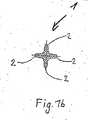
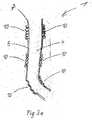
本発明に従った注射針1の第一の実施の形態が図1aないし図1dに示されている。該注射針は、管状の形態にて提供される形状記憶材料から完全に出来ている。図1a、図1bにおいて、注射針1は、組織内に挿入するのに適した剛性な状態をとる第一の形態にて示されている。この状態における形状記憶材料は、折り重ねた管のように形成され、このため、4つの端縁2が存在する。図1bから理解し得るように、この実施の形態における4つの端縁は、一方が他方に対しクロス形状に配置されている。管状の形状記憶材料の内部には、第一の形態にて中空の空間は存在しない。しかし、この1つの変更例において、中空の空間を第一の状態にて形成してもよい。管状の形状記憶材料の一端は、注射針1の先端3を形成する。先端3にて、端縁2は、共に1点まで伸びている。硬く且つ鋭利な要素の形態にて追加的な挿入補助具を先端3に設け、組織の表面を突き刺すことも考えられる。この折り重ね且つ剛性な第一の状態において、折り重ねた端縁2は一方が他方に対して支持する。注射針は、身体組織内に貫入するのに十分に剛性である。 A first embodiment of an
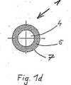
図1c及び図1dにおいて、第一の実施の形態に従った注射針は、注射針1が第一の状態と比較して撓み強度が低下した可撓性の第二の状態で示されており、このため、注射針は、より可撓性である、好ましくは弾性的に可撓性である。例えば、加熱又は入射放射線により管状の形状記憶材料を刺激することにより、形状記憶材料は、注射針が可撓性であり且つ流体が通るための内部通路4を有するその第二の形態をとる。この状態において、注射針は、第一の形態に従った折り重ね状態が打ち消され、管7は、図1dの断面図から理解し得るように円形の壁5が得られる管7の形態をとる。この状態において、注射針は、流体を組織内に供給するときに通る開口部6として開放した一端を有する。第二の状態における可撓性は、針材料の弾性率を低下させることを通じて実現される。これと代替的に、第一の状態における注射針の断面形状及び(又は)寸法は、第一の状態における幾何学的慣性モーメンが第二の状態におけるものよりも大きいように選ぶことができる。第一の状態において、弾性率及び慣性モーメントの双方は第二の状態におけるよりも大きいようにすることも考えられる。 In FIG. 1c and FIG. 1d, the injection needle according to the first embodiment is shown in a flexible second state in which the
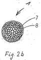
本発明に従った注射針1の第二の実施の形態が図2aないし図2cに示されている。図2aに示すように、注射針1は、形状記憶材料で出来た弾性管7を備えている。該管7は、注射針1の長手方向軸線に沿って伸びるファイバ束の形態をしたフィラー材料8を取り囲む。第一の状態において、形状記憶材料は、ファイバ束8を強固に取り囲み、このため、束8のファイバが管7内に緊密に圧密化した形態にて受け入れられる。束8の個別のファイバは、一方が他方に対し緊密に位置し、このため、これらファイバは一方を他方に対し支持し、このため、管7の内部に中空の空間は残らない。このため、第一の状態において、注射針1の曲がりは、ファイバの間の摩擦力による反作用を受ける。この状態において、注射針1を、身体組織内に押し込むことができる。管7は、前端にて2つの斜角面状端縁を有しており、このため、注射針を組織内に挿入するための先端3が形成される。図2bには、剛性な第一の状態、すなわち曲げ抵抗性がある注射針の断面が示されており、この状態において、束8のファイバは管7内にて一方が他方に対し緊密に位置する。 A second embodiment of the
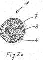
身体組織内に導入した後、管7は第二の状態に変化するよう刺激され、この第二の状態において、束8の個別のファイバは、最早、その一方が他方に対し押し付けられず、又は任意の程度にて一方が他方に対し緩くのみ押し付けられ、このため、通路4として機能するその間の隙間空間が寸法の点にて増大するか、又はその空間が最初に得られるようにする。この形態において、ルーズとなった束8のファイバは、一方が他方に対して動き且つ曲がることができる。 After introduction into the body tissue, the
管7のフィラー材料8は、必ずしもファイバの形態とする必要はないが、かかるフィラー材料であることが好ましい。原理上、注射針1が、第一の状態において、組織内に挿入するのに十分な剛性を有し、また、第二の状態において、十分な可撓性を有する限り、その他の適宜な形態とすることも可能である。例えば、フィラー材料8は、小球の形態としてもよい。管7は、かかるフィラー材料を取り囲み且つ互いに加圧する。 The
本発明に従った注射針1の第三の実施の形態が図3aに示されている。注射針1は管状の形態をしている。該注射針は形状記憶材料にて出来たものであることが望ましい。折り重ね領域10が注射針の長手方向軸線に沿った規則的な間隔にて管7の壁5に形成されており、該折り重ね領域にて、壁5は、注射針の長手方向軸線の長手方向に向けて互いに隣接して配置された周方向に伸びる折り重ね部を有する。形状記憶材料にて折り重ね領域10のみを形成し、且つこれらの間に位置する管の部分に対し別の材料を使用することも考えられる。 A third embodiment of the
第一の状態において、折り重ね領域10の個別の折り重ね層は一方が他方に当接する。折り重ね領域10を互いに注射針の長手方向軸線の長手方向に向けて更に加圧することはできない。このため、力が注射針の長手方向軸線の長手方向に向けて作用するとき、注射針1は剛性である。注射針の長手方向軸線に対して半径方向に作用する力が加えられたとき、注射針1は、長手方向軸線に対して折り重ね領域10にて曲がることができる。このようにして、折り重ね領域10の個別の折り重ね部は、図3aの最下方の折り重ね領域10にて示すように、外方に開放する。折り重ね領域が形状記憶材料で出来ているならば、力を長手方向に加えたときの剛性は、折り重ね領域10の折り重ね部を引き離すことができない形状記憶材料の第一の形態により支えることができる。第二の形態において、注射針1が身体組織内に挿入されたとき、折り重ね領域10における形状記憶材料は折り重ねられて分離し、注射針が挿入した状態にて可撓性であるようにすることができる。 In the first state, one of the individual folded layers of the folded
図3bには、図3aの第三の実施の形態と同様である、本発明に従った注射針1の第四の実施の形態が示されている。折り重ね領域10の代わりに、第四の実施の形態にて、孔領域11が設けられている。孔領域11内にて管7の壁は、周方向に一方が他方の後となるように配置された小さいスリットを有する。個別のスリットの列は、注射針の長手方向軸線の長手方向に向けて一方が他方の隣となるように配置されており、スリットは、相互に変位されている。スリットが壁を貫通するように設けられているならば、例えば、流体がスリットを通って注射針から逃げることがないように管の内部に薄い弾性的な外皮を設けることができる。しかし、例えば、流体を1つの正確な箇所ではなくて組織内の大きい表面積を亙って供給するならば、かかる外皮は廃止してよい。しかし、スリットはまた、管の内面又は外面内に深く達するが、管の壁を貫通して伸びないような形態とすることもできる。 FIG. 3b shows a fourth embodiment of the
長手方向に向けて注射針1に力が加わるとき、スリットは、互いに閉じた位置に位置し、このため、注射針は身体組織内に挿入するのに十分に剛性となる。注射針の軸線に対し半径方向に作用する力が加えられるとき、孔領域11内のスリットは一側部にて開放し、このため、注射針は、注射針の長手方向軸線に対し反対側部にて可撓性である。孔領域11の孔は、極めて多数の異なる形態をとることができ、例えば、該孔は凹凸状としてもよい。 When a force is applied to the
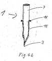
図3cには、図3aに示した第三の実施の形態に従った注射針1が示されており、この注射針1は、挿入補助具12を更に有している。上述したように、注射針の管7は、幾つかの箇所にて折り重ね領域10を有している。挿入補助具12は、伸長体13に配置された挿入先端12を備えている。伸長体13は、挿入先端12が注射針の第一の状態にて管7の端部から突き出すような仕方にて管7の内部に配置されている。伸長体13は、管7の内部にて取り付け箇所14に固定されている。取り付け箇所14は、管7の内部の箇所に位置しており、このため、取り付け箇所14と管7の端部との間に幾つかの折り重ね領域10が配置されている。第二の状態において、管7の折り重ね領域10の折り重ね部は展開する、すなわち引き離され、このため、取り付け箇所14から管の端部までの距離は増大する。第二の状態において、管は挿入補助具の挿入先端12の上を摺動する。この状態において、管は、挿入先端12に損傷に対する保護部を形成する。 FIG. 3 c shows the
図4a、図4bには、本発明に従った注射針1の第五の実施の形態が示されている。注射針は、身体組織内に挿入することを目的とする一端に、その壁に中空の空間15を有する管7を備えており、該中空の空間15は、壁の全周の周りを周方向に伸び、また、注射針を組織内に挿入するための注射針の全長に沿って多少なりとも長手方向に伸びている。中空の空間15にはゲルが充填される。第一の状態において、ゲルは、固体の形態を有し、このため、注射針1は、身体組織内に挿入するのに十分に剛性である。例えば、温度又はpH値の変化によりゲルを刺激することにより、ゲルは、注射針1が可撓性であるように柔軟な状態をとる。中空の空間15又は管7の端部にて、中空の空間又は管は、組織内に挿入する先端3を形成し得るよう、ある箇所までテーパー付きの設計とされている。先端3から遠方の端部にて、切り換え要素16を中空の空間15に配置することができ、該切り換え要素は、例えば、状態の変化を起動させ得るようゲルを刺激することができる。切り換え要素16は、注射時点にて、特に、機械的圧力又はその他の方法により励起させることができ、その励起がゲルの状態を変化させるスイッチを形成することができる。 4a and 4b show a fifth embodiment of the
図5には、本発明に従った注射針1の第六の実施の形態が示されている。注射針1は、その内部通路4がヘリカルばね17の形態をした支持構造体17を受け入れる管7を備えている。スペーサ18がヘリカルばね17の個別の巻線間を実質的に半径方向に伸びている。個別の巻線は、スペーサ18の端縁に当接する。力が長手方向に向けて注射針に作用するとき、個別のスペーサ18は、この方向に向けて一方が他方に押し付けられる。スペーサ18は非弾性的な形態のものであり、このため、力が長手方向に加えられたとき、注射針は剛性であり、また、注射針は組織内に挿入することができる。注射針の一側部から注射針の長手方向軸線に対して半径方向に作用する力が加えられたとき、反対側部におけるヘリカルばね17の巻線は一方が他方から離れるように移動する。この側部における巻線の間の距離は、スペーサ18の長さよりも長くなる。反対側部にて、巻線はスペーサ18に当接するままである。側部から挿入部に力が加えられたとき、注射針は、ヘリカルばね17の巻線が押し拡げられる結果として、この力に対し伸延することができる。 FIG. 5 shows a sixth embodiment of the
図6a、図6bには、本発明に従った注射針1の第七の実施の形態が示されている。注射針1は、管7を備えており、該管7は、その壁にて、注射針の長手方向軸線の長手方向に伸び且つ仕切り壁23により通路4から分離された隙間空間19を有する。隙間空間19は、管7の円周の周りにて周方向に完全に伸びないことが好ましい。例えば、グラニュールのようなフィラー材料20が隙間空間19内に供給される。 6a and 6b show a seventh embodiment of the
図6aにおいて、注射針1は、注射針1の管7の周りに配置されたリング21が隙間空間19内にグラニュール20を備える第一の状態にて示されている。これを行うため、リング21は、フィラー材料20が隙間空間19の端部壁22の方向に押し付けられるような仕方にて管7に沿って移動する。隙間空間19と流体が通るための通路4との間の仕切り壁23は、管7の材料よりも弾性的であることが好ましい。このため、リング21が管7に沿って移動するとき、フィラー材料を圧縮することにより、仕切り壁23は管の反対側の内壁に当接する迄、通路及び管の反対側の内壁の方向に膨張する。フィラー材料が圧縮された状態において、フィラー材料は、緊密に加圧され且つ剛性な形態をとり、このため、フィラー材料は、注射針1の管7に対する補強効果を提供する。注射針をこの状態にて身体組織内に挿入することができる。 In FIG. 6 a, the
図6bにおいて、リング21は、管7に沿って後方に移動している、すなわち、端部壁22から更に遠方に達している。この状態において、フィラー材料20は、隙間空間19内にてより長い長さに沿って押し拡げられ、このため、仕切り壁23は、後方に動き且つ、流体が通るための通路4を自由にする。その結果、管の前壁とフィラー材料20が配置された仕切り壁との間の距離が短くなり、このため、薄い材料層のみが存在する。リング21がフィラー材料をその圧縮状態から自由されたこの第二の状態において、フィラー材料20は隙間空間19内にて可動であり、また、注射針は可撓性である。原理上、単一の隙間空間に代えて、注射針又は管7の長手方向軸線に沿って配置された幾つかの隙間スペーサを提供することも可能である。更に、フィラー材料は、例えば、第二の実施の形態にて説明したのと同一の仕方にて形状記憶材料を備えることができる。 In FIG. 6 b, the
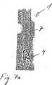
図7a、図7bには、第八の実施の形態における注射針1が示されている。注射針1は、組織内に挿入されるその全長に沿って均質な形状記憶材料で出来ている。図7aに示した第一の状態において、注射針は直線状であり、組織内に挿入するのに十分な撓み強度を有している。注射針は、特に、熱可塑性ポリマーにて出来たものとすることができる。図7bには、組織内に挿入した後の第八の実施の形態の注射針1が示されている。組織内にて優勢な状態のため、注射針1の材料は第一の状態から第二の状態に変化し、該第二の状態において、注射針は柔軟であり、注射針は、組織内にて生ずる荷重を受けて弾性的に曲がる。第八の実施の形態の材料の弾性率は、組織内にて優勢な状態下にて減少する。組織外の雰囲気状態において、注射針は、好ましくは少なくとも3000MPaの弾性率を有する。これに反して、挿入された状態において、注射針は、最大1000MPa、例えば、700MPaの弾性率のみを有する。状態の変化は、特に、ポリマーが非結晶状態に転移することにより生じさせることができる。ポリマーは、組織の温度にあり又は好ましくは組織の温度より僅かに低いが、通常の雰囲気温度よりも高いガラス転移温度を有するから、状態の変化は、温度変化により実現されることが好ましい。このため、ガラス転移温度は、少なくとも30℃、好ましくは32℃とし、最大で、体温、好ましくは最高36℃に相応とするものでなければならない。注射針1には、鋭利な切刃部を形成する先端が設けられる。この先端はまた、挿入された状態にて極めて柔軟である、すなわち、最早、切断することができないことが望ましい。第一の状態及び第二の状態における、第八の実施の形態の注射針1は注射カニューレである、すなわち、双方の状態において、注射針は、投与すべき流体が通るための内部通路4を有している。 7a and 7b show the
図8a、図8bには、同様に双方の状態にてカニューレである第九の実施の形態における注射針1が示されている。第九の実施の形態のおいて、注射針1は、その全長に沿って管7として複合材料から出来ている。複合材料は、第一の材料24で出来た支持基質と、支持基質内に埋め込まれた固体粒子25とから成っている。固体粒子25の体積比率は、注射針1の先端からその基端に向けて連続的に減少する。先端に形成された切刃部にて直接、フィラー材料25の体積比率は約70%であり、この値は、注射針1の基端に向けて、すなわち、組織内に挿入すべき注射針1の長さに沿って20%以下、好ましくは10ないし15%の比率まで低下する。支持基質24の材料は、同様に、挿入された状態における弾性率が挿入前のものよりも小さい材料である。特に、熱可塑性ポリマーは、支持基質材料を形成することができ、第八の実施の形態に関する説明は、このポリマーにも当て嵌まることが好ましい。管7は、身体外の雰囲気状態にて剛性であり、この第一の状態において、挿入のための管を形成するものと見なすことができる。第二の状態において、管は弾性的に可撓性である。 FIGS. 8a and 8b show the
1cは、可撓性の第二の状態にある第一の実施の形態に従った注射針の縦断面図である。
1dは、図1cに従った注射針の断面図である。
1d is a cross-sectional view of the injection needle according to FIG. 1c.
2bは、図2aの注射針の断面図である。
2cは、可撓性の第二の状態にある第二の実施の形態に従った注射針の断面図である。
2c is a cross-sectional view of the injection needle according to the second embodiment in the flexible second state.
3bは、本発明に従った注射針の第四の実施の形態を示す概略図である。
3cは、本発明に従った注射針の第三の実施の形態を示す概略図である。
3c is a schematic view showing a third embodiment of the injection needle according to the present invention.
4bは、可撓性の第二の状態にある第五の実施の形態を示す概略図である。
7bは、可撓性の第二の状態にある第八の実施の形態の注射針を示す図である。
8bは、可撓性の第二の状態にある第九の実施の形態の注射針を示す図である。 8b is a view showing the injection needle of the ninth embodiment in the flexible second state.
1 注射針の長手方向軸線
2 端部
3 先端
4 通路
5 壁
6 開口部
7 管/形状記憶材料
8 フィラー材料
9 −
10 折り重ね領域
11 孔領域
12 挿入先端
13 伸長体
14 取り付け箇所
15 中空の空間
16 切り換え要素
17 ヘリカルばね
18 スペーサ
19 隙間空間
20 フィラー材料
21 リング
22 端部壁
23 仕切り壁
24 支持基質
25 フィラー材料DESCRIPTION OF
DESCRIPTION OF
Claims (9)
Translated fromJapanese単一の管状部材から成り、身体組織に挿入するために鋭利な先端縁を有し、
第一の状態において、挿入に十分な撓み強度を有し、また、第二の状態において減少した撓み強度を有する少なくとも1つの材料(7)により少なくとも部分的に形成され、
力が長手方向に向けて注射針(1)に加わるとき剛性であり、力が注射針の長手方向軸線に対して半径方向に加わるとき可撓性であり、
注射針(1)が、第一の状態において、その円周に長手方向に伸びる少なくとも1つの端縁(2)を有し、第二の状態において、端縁無しの円周を有することを特徴とする、注射針。In an injection needle (1) for injection into body tissue, which is flexible in the inserted state and has a passage for introducing fluid,
Consisting of a single tubular member, with a sharp tip edge for insertion into body tissue,
In a first state, it has sufficient flexural strength to insertion, addition,aremore at least partially formed on at least one material (7) having a reduced flexural strength in the secondstate,
Force is rigid when applied to the injection needle (1) toward the longitudinal direction,Ri flexible der when a force is applied radially relative to the longitudinal axis of theneedle,
The injection needle (1) has at least one edge (2) extending longitudinally around its circumference in the first state and has a circumference without an edge in the second state. And an injection needle.
単一の管状部材から成り、身体組織に挿入するために鋭利な先端縁を有し、
第一の状態において、挿入に十分な撓み強度を有し、また、第二の状態において減少した撓み強度を有する少なくとも1つの材料(7)により少なくとも部分的に形成され、
力が長手方向に向けて注射針(1)に加わるとき剛性であり、力が注射針の長手方向軸線に対して半径方向に加わるとき可撓性であり、
第一の状態において、内部の中空の空間が存在しない設計とされ、第二の状態において、注射針の長手方向軸線に沿った内部通路(4)が存在する設計とされることを特徴とする、注射針。In an injection needle (1) for injection into body tissue, which is flexible in the inserted state and has a passage for introducing fluid,
Consisting of a single tubular member, with a sharp tip edge for insertion into body tissue,
In a first state, it has sufficient flexural strength to insertion, addition,aremore at least partially formed on at least one material (7) having a reduced flexural strength in the secondstate,
Force is rigid when applied to the injection needle (1) toward the longitudinal direction,Ri flexible der when a force is applied radially relative to the longitudinal axis of theneedle,
In the first state, the design is such that there is no internal hollow space, and in the second state, the design is such that there is an internal passage (4) along the longitudinal axis of the injection needle. ,Needle.
単一の管状部材から成り、身体組織に挿入するために鋭利な先端縁を有し、
第一の状態において、挿入に十分な撓み強度を有し、また、第二の状態において減少した撓み強度を有する少なくとも1つの材料(7)により少なくとも部分的に形成され、
力が長手方向に向けて注射針(1)に加わるとき剛性であり、力が注射針の長手方向軸線に対して半径方向に加わるとき可撓性であり、
第一の状態において、閉じた先端(3)を有し、第二の状態において、先端(3)の開口部(6)を有することを特徴とする、注射針。In an injection needle (1) for injection into body tissue, which is flexible in the inserted state and has a passage for introducing fluid,
Consisting of a single tubular member, with a sharp tip edge for insertion into body tissue,
In a first state, it has sufficient flexural strength to insertion, addition,aremore at least partially formed on at least one material (7) having a reduced flexural strength in the secondstate,
Force is rigid when applied to the injection needle (1) toward the longitudinal direction,Ri flexible der when a force is applied radially relative to the longitudinal axis of theneedle,
An injection needle having a closed tip (3) in the first state and an opening (6) in the tip (3) in the second state.
Applications Claiming Priority (3)
| Application Number | Priority Date | Filing Date | Title |
|---|---|---|---|
| CH732003 | 2003-01-17 | ||
| DE2003106013DE10306013A1 (en) | 2003-01-17 | 2003-02-13 | Simplified and improved temperature-sensitive cannula for e.g. longer-term infusion, softens following insertion at a critical temperature |
| PCT/EP2004/000309WO2004064898A1 (en) | 2003-01-17 | 2004-01-16 | Flexible injection needle |
Publications (2)
| Publication Number | Publication Date |
|---|---|
| JP2006514873A JP2006514873A (en) | 2006-05-18 |
| JP4611278B2true JP4611278B2 (en) | 2011-01-12 |
Family
ID=32772545
Family Applications (1)
| Application Number | Title | Priority Date | Filing Date |
|---|---|---|---|
| JP2006500584AExpired - Fee RelatedJP4611278B2 (en) | 2003-01-17 | 2004-01-16 | Flexible needle |
Country Status (8)
| Country | Link |
|---|---|
| US (2) | US7513891B2 (en) |
| EP (1) | EP1583572B1 (en) |
| JP (1) | JP4611278B2 (en) |
| AT (1) | ATE361109T1 (en) |
| CA (1) | CA2511574C (en) |
| DE (1) | DE502004003673D1 (en) |
| ES (1) | ES2285412T3 (en) |
| WO (2) | WO2004064898A1 (en) |
Families Citing this family (76)
| Publication number | Priority date | Publication date | Assignee | Title |
|---|---|---|---|---|
| EP1515775A4 (en) | 2002-05-07 | 2010-03-03 | Oncostim Inc | Method and device for treating concer with electrical therapy in conjunction with chemotherapeutic agents and radiation therapy |
| DE102004002472B4 (en)* | 2004-01-16 | 2007-09-13 | Disetronic Licensing Ag | needle |
| MXPA06010784A (en) | 2004-03-26 | 2006-12-15 | Unomedical As | Injector device for infusion set. |
| US8062250B2 (en) | 2004-08-10 | 2011-11-22 | Unomedical A/S | Cannula device |
| DE102004039408A1 (en) | 2004-08-13 | 2006-03-02 | Disetronic Licensing Ag | Insertion head for medical or pharmaceutical applications |
| JP4982637B2 (en)* | 2004-12-15 | 2012-07-25 | クック メディカル テクノロジーズ エルエルシー | Flexible surgical needle device |
| US7985199B2 (en) | 2005-03-17 | 2011-07-26 | Unomedical A/S | Gateway system |
| EP1762259B2 (en) | 2005-09-12 | 2025-01-01 | Unomedical A/S | Inserter for an infusion set with a first and second spring units |
| US8251963B2 (en) | 2005-12-08 | 2012-08-28 | Boston Scientific Scimed, Inc. | Flexible needle |
| DK1962926T3 (en) | 2005-12-23 | 2009-09-28 | Unomedical As | injection device |
| WO2007098771A2 (en) | 2006-02-28 | 2007-09-07 | Unomedical A/S | Inserter for infusion part and infusion part provided with needle protector |
| CA2653631A1 (en) | 2006-06-07 | 2007-12-13 | Unomedical A/S | Inserter |
| CA2653764A1 (en) | 2006-06-09 | 2007-12-13 | Unomedical A/S | Mounting pad |
| US8882715B2 (en) | 2006-07-31 | 2014-11-11 | Carlos Jaramillo | Catheterization device and method |
| JP2009545341A (en) | 2006-08-02 | 2009-12-24 | ウノメディカル アクティーゼルスカブ | Cannula and delivery device |
| EP1917990A1 (en) | 2006-10-31 | 2008-05-07 | Unomedical A/S | Infusion set |
| ATE514442T1 (en)* | 2007-02-02 | 2011-07-15 | Unomedical As | GATEWAY DEVICE |
| ATE485858T1 (en) | 2007-03-14 | 2010-11-15 | Hoffmann La Roche | INSERTION HEAD FOR MEDICAL OR PHARMACEUTICAL APPLICATIONS |
| ATE477011T1 (en) | 2007-03-14 | 2010-08-15 | Hoffmann La Roche | INSERTION DEVICE FOR AN INSERTION HEAD, IN PARTICULAR FOR AN INFUSION SET |
| EP2155311B1 (en) | 2007-06-20 | 2013-01-02 | Unomedical A/S | A method and an apparatus for making a catheter |
| AU2008270327A1 (en) | 2007-07-03 | 2009-01-08 | Unomedical A/S | Inserter having bistable equilibrium states |
| DE602008005153D1 (en) | 2007-07-10 | 2011-04-07 | Unomedical As | INSERT WITH TWO SPRINGS |
| AU2008277763B2 (en) | 2007-07-18 | 2011-11-10 | Unomedical A/S | Insertion device with pivoting action |
| ATE522240T1 (en) | 2008-02-13 | 2011-09-15 | Unomedical As | SEAL BETWEEN A CANNULAR PART AND A FLUID PATH |
| US9566384B2 (en) | 2008-02-20 | 2017-02-14 | Unomedical A/S | Insertion device with horizontally moving part |
| US7938800B2 (en)* | 2008-05-13 | 2011-05-10 | Lawrence R. Koh and Nina Merrell-Koh | Needleshield assembly and methods of use |
| EP2326274B8 (en)* | 2008-08-20 | 2019-11-27 | Prostacare Pty Ltd | Catheter for treating tissue with non-thermal ablation |
| US9597145B2 (en) | 2008-08-20 | 2017-03-21 | Prostacare Pty Ltd | Non-thermal ablation system for treating tissue |
| AU2009331635A1 (en) | 2008-12-22 | 2011-06-23 | Unomedical A/S | Medical device comprising adhesive pad |
| EP3384942B1 (en)* | 2009-01-12 | 2025-09-17 | Becton, Dickinson and Company | Infusion set and/or patch pump having at least one of an in-dwelling rigid catheter with flexible features and/or a flexible catheter attachment |
| EP2250959A1 (en) | 2009-05-13 | 2010-11-17 | Roche Diagnostics GmbH | Controllable sensor insertion needle |
| WO2010144545A1 (en)* | 2009-06-09 | 2010-12-16 | Vascular Technology, Inc. | Soft tissue dissector |
| AU2010277755A1 (en) | 2009-07-30 | 2012-02-02 | Unomedical A/S | Inserter device with horizontal moving part |
| KR20120047896A (en) | 2009-08-07 | 2012-05-14 | 우노메디컬 에이/에스 | Delivery device with sensor and one or more cannulas |
| JP2013505743A (en)* | 2009-09-25 | 2013-02-21 | エスエスビー テクノロジー プロプライエタリー リミテッド | Lockable syringe system |
| US10973994B2 (en)* | 2013-09-16 | 2021-04-13 | Pourang Bral | Means and method to invade skin, mucosa, and underlying tissues with little or no pain |
| US9770560B2 (en) | 2009-11-12 | 2017-09-26 | Pourang Bral | Means and method to administer injections with little or no pain |
| EP2589408A3 (en)* | 2010-01-29 | 2013-05-29 | Ubiomed Inc. | Micro needle and micro needle apparatus |
| KR20130018783A (en) | 2010-03-30 | 2013-02-25 | 우노메디컬 에이/에스 | Medical device |
| EP2433663A1 (en) | 2010-09-27 | 2012-03-28 | Unomedical A/S | Insertion system |
| EP2436412A1 (en) | 2010-10-04 | 2012-04-04 | Unomedical A/S | A sprinkler cannula |
| US10106278B2 (en) | 2011-01-28 | 2018-10-23 | Aquavit Pharmaceuticals, Inc. | System and method for personalized injection treatment |
| EP2667965B1 (en) | 2011-01-28 | 2016-07-27 | Aquavit Pharmaceuticals, Inc. | System and method for personalized injection treatment |
| US20120197396A1 (en)* | 2011-01-31 | 2012-08-02 | Berg Jeffrey H | Hybrid solid-flexible passing pin and anterior cruciate ligament repair using the pin |
| WO2013050277A1 (en) | 2011-10-05 | 2013-04-11 | Unomedical A/S | Inserter for simultaneous insertion of multiple transcutaneous parts |
| EP2583715A1 (en) | 2011-10-19 | 2013-04-24 | Unomedical A/S | Infusion tube system and method for manufacture |
| US9440051B2 (en) | 2011-10-27 | 2016-09-13 | Unomedical A/S | Inserter for a multiplicity of subcutaneous parts |
| US9192375B2 (en)* | 2012-02-29 | 2015-11-24 | Marker Medical, Llc | Surgical apparatus and method |
| US9717554B2 (en) | 2012-03-26 | 2017-08-01 | Biosense Webster (Israel) Ltd. | Catheter with composite construction |
| US9737671B2 (en)* | 2012-04-20 | 2017-08-22 | Steven Williams | Trocar assemblies |
| US10639099B2 (en) | 2012-05-25 | 2020-05-05 | Biosense Webster (Israel), Ltd. | Catheter having a distal section with spring sections for biased deflection |
| US10980865B2 (en)* | 2012-08-10 | 2021-04-20 | Aquavit Pharmaceuticals, Inc. | Direct application system and method for the delivery of bioactive compositions and formulations |
| EP2895221B1 (en)* | 2012-09-14 | 2016-05-18 | Fresenius Kabi Deutschland GmbH | Medical injection device |
| US20140213866A1 (en) | 2012-10-12 | 2014-07-31 | Dexcom, Inc. | Sensors for continuous analyte monitoring, and related methods |
| US20140107450A1 (en) | 2012-10-12 | 2014-04-17 | Dexcom, Inc. | Sensors for continuous analyte monitoring, and related methods |
| CN108433732B (en)* | 2013-03-12 | 2021-05-28 | 木兰医药技术股份有限公司 | Apparatus and method for selectively occluding a lumen of a needle body |
| US10548628B2 (en) | 2013-03-15 | 2020-02-04 | Vanderbilt University | Steerable surgical needle |
| US9295512B2 (en)* | 2013-03-15 | 2016-03-29 | Myoscience, Inc. | Methods and devices for pain management |
| US9610112B2 (en)* | 2013-03-15 | 2017-04-04 | Myoscience, Inc. | Cryogenic enhancement of joint function, alleviation of joint stiffness and/or alleviation of pain associated with osteoarthritis |
| US20150289788A1 (en) | 2014-04-10 | 2015-10-15 | Dexcom, Inc. | Sensors for continuous analyte monitoring, and related methods |
| US10279124B2 (en) | 2015-01-22 | 2019-05-07 | Aesynt Incorporated | Expanding needle device and method of expansion for the transfer of fluids |
| WO2017087888A1 (en) | 2015-11-18 | 2017-05-26 | President And Fellows Of Harvard College | Systems and methods for monitoring, managing, and treating asthma and anaphylaxis |
| US10113537B2 (en) | 2016-04-08 | 2018-10-30 | Ecole Polytechnique Federale De Lausanne (Epfl) | Variable stiffness device and method of manufacturing the same |
| US10220195B2 (en) | 2016-06-08 | 2019-03-05 | Eclipse Medcorp, Llc | Radio frequency needling device for use with disposable needle cartridges |
| US9629991B1 (en) | 2016-06-08 | 2017-04-25 | Eclipse Aesthetics, LLC | Disposable radio frequency needle cartridges having absorbing containment barriers |
| US9636491B1 (en) | 2016-06-08 | 2017-05-02 | Eclipse Aesthetics, LLC | Disposable needle cartridges having absorbing contaminant barriers |
| EP3630257A4 (en) | 2017-05-26 | 2021-03-17 | Piper Access, LLC | Catheter delivery devices, systems, and methods |
| EP3449965A1 (en)* | 2017-09-05 | 2019-03-06 | ETH Zurich | Steerable catheter with portions of different stiffness |
| WO2019104326A1 (en) | 2017-11-27 | 2019-05-31 | Prostacare Pty Ltd | An apparatus and a method for the treatment of a prostatic disease |
| CN109985303B (en)* | 2017-12-29 | 2022-09-23 | 东莞科威医疗器械有限公司 | Medical intubation and manufacturing process thereof |
| WO2019168949A1 (en) | 2018-02-28 | 2019-09-06 | Prostacare Pty Ltd | System for managing high impedance changes in a non-thermal ablation system for bph |
| US11471650B2 (en) | 2019-09-20 | 2022-10-18 | Biosense Webster (Israel) Ltd. | Mechanism for manipulating a puller wire |
| JP2021109007A (en)* | 2020-01-14 | 2021-08-02 | 持田製薬株式会社 | needle |
| US11202753B1 (en) | 2020-03-06 | 2021-12-21 | Aquavit Pharmaceuticals, Inc. | Systems and methods for generating immune responses in subjects using microchannel delivery devices |
| TW202448544A (en) | 2023-02-15 | 2024-12-16 | 瑞士商赫孚孟拉羅股份公司 | Insertion system and method for inserting a medical device |
| KR102661017B1 (en)* | 2023-04-10 | 2024-04-29 | 한국과학기술원 | Body temperature-responsive, stiffness-varying and non-reusable intravenous needle with on-site temperature sensing for improved patient care, intravenous infusion set having the same, and manufacturing method of the same |
Family Cites Families (28)
| Publication number | Priority date | Publication date | Assignee | Title |
|---|---|---|---|---|
| US2828744A (en)* | 1956-02-13 | 1958-04-01 | Hirsch Sidney | Flexible needle for use in intravenous therapy |
| US3830239A (en)* | 1972-09-12 | 1974-08-20 | Frigitronics Of Conn Inc | Cryosurgical device |
| US4022215A (en)* | 1973-12-10 | 1977-05-10 | Benson Jerrel W | Cryosurgical system |
| US3986506A (en)* | 1974-09-03 | 1976-10-19 | Baxter Travenol Laboratories, Inc. | Apparatus for separation of cryoprecipitate from blood plasma and method |
| US4562751A (en) | 1984-01-06 | 1986-01-07 | Nason Clyde K | Solenoid drive apparatus for an external infusion pump |
| US4790817A (en)* | 1985-03-28 | 1988-12-13 | Luther Medical Products, Inc. | Assembly of stylet and catheter, and needle and catheter |
| US4664660A (en)* | 1985-04-01 | 1987-05-12 | Becton, Dickinson And Company | Chest drainage apparatus with ambient air sealing |
| US4755173A (en) | 1986-02-25 | 1988-07-05 | Pacesetter Infusion, Ltd. | Soft cannula subcutaneous injection set |
| US4841970A (en)* | 1988-01-26 | 1989-06-27 | Herbert Rand | Cryogenic rectal insert |
| JP2561853B2 (en)* | 1988-01-28 | 1996-12-11 | 株式会社ジェイ・エム・エス | Shaped memory molded article and method of using the same |
| WO1990011793A1 (en)* | 1989-04-13 | 1990-10-18 | Mitsubishi Cable Industries, Ltd. | Catheter |
| US5141497A (en)* | 1989-06-06 | 1992-08-25 | Becton, Dickinson And Company | Apparatus and method for an introducer |
| US4976704A (en)* | 1989-07-17 | 1990-12-11 | Mclees Donald J | Moisture disabled needle |
| JP2723190B2 (en)* | 1989-07-28 | 1998-03-09 | 株式会社ニッショー | Indwelling needle |
| US5219358A (en)* | 1991-08-29 | 1993-06-15 | Ethicon, Inc. | Shape memory effect surgical needles |
| US5853408A (en)* | 1992-08-20 | 1998-12-29 | Advanced Cardiovascular Systems, Inc. | In-vivo modification of the mechanical properties of surgical devices |
| US5445140A (en)* | 1993-06-07 | 1995-08-29 | United States Surgical Corporation | Endoscopic surgical device |
| US5624727A (en)* | 1994-12-14 | 1997-04-29 | S.K.Y. Polymers, Inc. | Structural devices with changing mechanical properties responsive to external forces |
| WO1996036860A2 (en) | 1995-05-01 | 1996-11-21 | Ep Technologies, Inc. | Systems and methods for sensing sub-surface temperatures in body tissue during ablation with actively cooled electrodes |
| US5885258A (en)* | 1996-02-23 | 1999-03-23 | Memory Medical Systems, Inc. | Medical instrument with slotted memory metal tube |
| US5800421A (en)* | 1996-06-12 | 1998-09-01 | Lemelson; Jerome H. | Medical devices using electrosensitive gels |
| US6096012A (en)* | 1996-08-27 | 2000-08-01 | Johnson & Johnson Medical, Inc. | Coated one-piece composite plastic catheter and cannula |
| US5762630A (en)* | 1996-12-23 | 1998-06-09 | Johnson & Johnson Medical, Inc. | Thermally softening stylet |
| JPH1176403A (en)* | 1997-07-11 | 1999-03-23 | Olympus Optical Co Ltd | Surgical treatment instrument |
| DE19738942A1 (en) | 1997-09-05 | 1999-03-25 | Pulsion Verwaltungs Gmbh & Co | Method and device for determining the injection time and duration of injection in thermodilution measurements |
| JP2002017855A (en)* | 2000-07-04 | 2002-01-22 | Nihon Medi Physics Co Ltd | Plunger for radiopharmaceutical syringe |
| WO2002028458A1 (en)* | 2000-10-06 | 2002-04-11 | Maxwell Edmund Whisson | Body heat actuated parenteral device |
| US6616680B1 (en)* | 2000-11-01 | 2003-09-09 | Joseph M. Thielen | Distal protection and delivery system and method |
- 2004
- 2004-01-16JPJP2006500584Apatent/JP4611278B2/ennot_activeExpired - Fee Related
- 2004-01-16ATAT04702689Tpatent/ATE361109T1/enactive
- 2004-01-16WOPCT/EP2004/000309patent/WO2004064898A1/enactiveIP Right Grant
- 2004-01-16WOPCT/EP2004/000310patent/WO2004064593A2/enactiveApplication Filing
- 2004-01-16ESES04702689Tpatent/ES2285412T3/ennot_activeExpired - Lifetime
- 2004-01-16DEDE502004003673Tpatent/DE502004003673D1/ennot_activeExpired - Lifetime
- 2004-01-16EPEP04702689Apatent/EP1583572B1/ennot_activeExpired - Lifetime
- 2004-01-16CACA2511574Apatent/CA2511574C/ennot_activeExpired - Fee Related
- 2005
- 2005-07-15USUS11/183,270patent/US7513891B2/ennot_activeExpired - Fee Related
- 2005-07-15USUS11/182,524patent/US7435240B2/ennot_activeExpired - Fee Related
Also Published As
| Publication number | Publication date |
|---|---|
| CA2511574A1 (en) | 2004-08-05 |
| US7513891B2 (en) | 2009-04-07 |
| WO2004064898A1 (en) | 2004-08-05 |
| JP2006514873A (en) | 2006-05-18 |
| ATE361109T1 (en) | 2007-05-15 |
| ES2285412T3 (en) | 2007-11-16 |
| US20060030824A1 (en) | 2006-02-09 |
| WO2004064593A3 (en) | 2004-09-16 |
| EP1583572B1 (en) | 2007-05-02 |
| CA2511574C (en) | 2011-07-19 |
| EP1583572A1 (en) | 2005-10-12 |
| US20050283125A1 (en) | 2005-12-22 |
| DE502004003673D1 (en) | 2007-06-14 |
| US7435240B2 (en) | 2008-10-14 |
| WO2004064593A2 (en) | 2004-08-05 |
Similar Documents
| Publication | Publication Date | Title |
|---|---|---|
| JP4611278B2 (en) | Flexible needle | |
| JP6375292B2 (en) | Crushable inflatable catheter | |
| JP4940390B2 (en) | Medical device having knitted structure and coil | |
| US6361528B1 (en) | Dynamically compliant catheter | |
| US6979321B2 (en) | Apparatus for inserting particles into tissue, in particular muscle tissue | |
| US6659996B1 (en) | Device for delivering biological agents | |
| US10173039B2 (en) | Balloon catheter | |
| JP2008515567A (en) | Reinforced and drug-eluting balloon catheter and method for manufacturing the same | |
| WO1999015068A2 (en) | Optical endoscopic portals and methods of using the same to establish passages through cavity walls | |
| US7758549B2 (en) | Injection needle assembly comprising an injection needle and a needle guide | |
| WO2009097650A1 (en) | Expandable catheter | |
| US20140243783A1 (en) | Method of backflow reduction during material delivery through a needle into tissue | |
| US20040193113A1 (en) | Expandable bore injection needle | |
| JP2022552859A (en) | Guide member for controllable vascular expansion system and controllable vascular expansion system | |
| US8945045B2 (en) | Needleless injection device components, systems, and methods | |
| CN117729957A (en) | Indwelling cannula | |
| US8858514B2 (en) | Internal device for injection and sampling of a liquid inside a living organism | |
| KR101610282B1 (en) | Balloon Catheter | |
| KR102360445B1 (en) | A Rigidity Adjustable Catheter | |
| JP2005342503A (en) | Balloon catheter |
Legal Events
| Date | Code | Title | Description |
|---|---|---|---|
| A621 | Written request for application examination | Free format text:JAPANESE INTERMEDIATE CODE: A621 Effective date:20060801 | |
| A131 | Notification of reasons for refusal | Free format text:JAPANESE INTERMEDIATE CODE: A131 Effective date:20090706 | |
| A521 | Request for written amendment filed | Free format text:JAPANESE INTERMEDIATE CODE: A523 Effective date:20090930 | |
| A02 | Decision of refusal | Free format text:JAPANESE INTERMEDIATE CODE: A02 Effective date:20100308 | |
| A521 | Request for written amendment filed | Free format text:JAPANESE INTERMEDIATE CODE: A523 Effective date:20100707 | |
| A521 | Request for written amendment filed | Free format text:JAPANESE INTERMEDIATE CODE: A821 Effective date:20100707 | |
| A911 | Transfer to examiner for re-examination before appeal (zenchi) | Free format text:JAPANESE INTERMEDIATE CODE: A911 Effective date:20100729 | |
| TRDD | Decision of grant or rejection written | ||
| A01 | Written decision to grant a patent or to grant a registration (utility model) | Free format text:JAPANESE INTERMEDIATE CODE: A01 Effective date:20100914 | |
| A01 | Written decision to grant a patent or to grant a registration (utility model) | Free format text:JAPANESE INTERMEDIATE CODE: A01 | |
| A61 | First payment of annual fees (during grant procedure) | Free format text:JAPANESE INTERMEDIATE CODE: A61 Effective date:20101013 | |
| FPAY | Renewal fee payment (event date is renewal date of database) | Free format text:PAYMENT UNTIL: 20131022 Year of fee payment:3 | |
| R150 | Certificate of patent or registration of utility model | Free format text:JAPANESE INTERMEDIATE CODE: R150 | |
| LAPS | Cancellation because of no payment of annual fees |