JP4611208B2 - Blood component measuring method, sensor and measuring apparatus used therefor - Google Patents
Blood component measuring method, sensor and measuring apparatus used thereforDownload PDFInfo
- Publication number
- JP4611208B2 JP4611208B2JP2005515983AJP2005515983AJP4611208B2JP 4611208 B2JP4611208 B2JP 4611208B2JP 2005515983 AJP2005515983 AJP 2005515983AJP 2005515983 AJP2005515983 AJP 2005515983AJP 4611208 B2JP4611208 B2JP 4611208B2
- Authority
- JP
- Japan
- Prior art keywords
- electrode
- blood
- sensor
- electrode system
- voltage
- Prior art date
- Legal status (The legal status is an assumption and is not a legal conclusion. Google has not performed a legal analysis and makes no representation as to the accuracy of the status listed.)
- Expired - Fee Related
Links
Images


Classifications
- A—HUMAN NECESSITIES
- A61—MEDICAL OR VETERINARY SCIENCE; HYGIENE
- A61B—DIAGNOSIS; SURGERY; IDENTIFICATION
- A61B5/00—Measuring for diagnostic purposes; Identification of persons
- A61B5/14—Devices for taking samples of blood ; Measuring characteristics of blood in vivo, e.g. gas concentration within the blood, pH-value of blood
- G—PHYSICS
- G01—MEASURING; TESTING
- G01N—INVESTIGATING OR ANALYSING MATERIALS BY DETERMINING THEIR CHEMICAL OR PHYSICAL PROPERTIES
- G01N27/00—Investigating or analysing materials by the use of electric, electrochemical, or magnetic means
- G01N27/26—Investigating or analysing materials by the use of electric, electrochemical, or magnetic means by investigating electrochemical variables; by using electrolysis or electrophoresis
- G01N27/28—Electrolytic cell components
- G01N27/30—Electrodes, e.g. test electrodes; Half-cells
- G01N27/327—Biochemical electrodes, e.g. electrical or mechanical details for in vitro measurements
- G01N27/3271—Amperometric enzyme electrodes for analytes in body fluids, e.g. glucose in blood
- G01N27/3274—Corrective measures, e.g. error detection, compensation for temperature or hematocrit, calibration
- C—CHEMISTRY; METALLURGY
- C12—BIOCHEMISTRY; BEER; SPIRITS; WINE; VINEGAR; MICROBIOLOGY; ENZYMOLOGY; MUTATION OR GENETIC ENGINEERING
- C12Q—MEASURING OR TESTING PROCESSES INVOLVING ENZYMES, NUCLEIC ACIDS OR MICROORGANISMS; COMPOSITIONS OR TEST PAPERS THEREFOR; PROCESSES OF PREPARING SUCH COMPOSITIONS; CONDITION-RESPONSIVE CONTROL IN MICROBIOLOGICAL OR ENZYMOLOGICAL PROCESSES
- C12Q1/00—Measuring or testing processes involving enzymes, nucleic acids or microorganisms; Compositions therefor; Processes of preparing such compositions
- C12Q1/001—Enzyme electrodes
- C12Q1/005—Enzyme electrodes involving specific analytes or enzymes
- C12Q1/006—Enzyme electrodes involving specific analytes or enzymes for glucose
- G—PHYSICS
- G01—MEASURING; TESTING
- G01N—INVESTIGATING OR ANALYSING MATERIALS BY DETERMINING THEIR CHEMICAL OR PHYSICAL PROPERTIES
- G01N27/00—Investigating or analysing materials by the use of electric, electrochemical, or magnetic means
- G01N27/26—Investigating or analysing materials by the use of electric, electrochemical, or magnetic means by investigating electrochemical variables; by using electrolysis or electrophoresis
- G—PHYSICS
- G01—MEASURING; TESTING
- G01N—INVESTIGATING OR ANALYSING MATERIALS BY DETERMINING THEIR CHEMICAL OR PHYSICAL PROPERTIES
- G01N33/00—Investigating or analysing materials by specific methods not covered by groups G01N1/00 - G01N31/00
- G01N33/48—Biological material, e.g. blood, urine; Haemocytometers
- G01N33/483—Physical analysis of biological material
- G01N33/487—Physical analysis of biological material of liquid biological material
- G—PHYSICS
- G01—MEASURING; TESTING
- G01N—INVESTIGATING OR ANALYSING MATERIALS BY DETERMINING THEIR CHEMICAL OR PHYSICAL PROPERTIES
- G01N33/00—Investigating or analysing materials by specific methods not covered by groups G01N1/00 - G01N31/00
- G01N33/48—Biological material, e.g. blood, urine; Haemocytometers
- G01N33/50—Chemical analysis of biological material, e.g. blood, urine; Testing involving biospecific ligand binding methods; Immunological testing
- G01N33/66—Chemical analysis of biological material, e.g. blood, urine; Testing involving biospecific ligand binding methods; Immunological testing involving blood sugars, e.g. galactose
- G—PHYSICS
- G01—MEASURING; TESTING
- G01N—INVESTIGATING OR ANALYSING MATERIALS BY DETERMINING THEIR CHEMICAL OR PHYSICAL PROPERTIES
- G01N33/00—Investigating or analysing materials by specific methods not covered by groups G01N1/00 - G01N31/00
- G01N33/48—Biological material, e.g. blood, urine; Haemocytometers
- G01N33/50—Chemical analysis of biological material, e.g. blood, urine; Testing involving biospecific ligand binding methods; Immunological testing
- G01N33/72—Chemical analysis of biological material, e.g. blood, urine; Testing involving biospecific ligand binding methods; Immunological testing involving blood pigments, e.g. haemoglobin, bilirubin or other porphyrins; involving occult blood
- G01N33/728—Bilirubin; including biliverdin
Landscapes
- Health & Medical Sciences (AREA)
- Life Sciences & Earth Sciences (AREA)
- Chemical & Material Sciences (AREA)
- Engineering & Computer Science (AREA)
- Hematology (AREA)
- Molecular Biology (AREA)
- Immunology (AREA)
- Physics & Mathematics (AREA)
- General Health & Medical Sciences (AREA)
- Biomedical Technology (AREA)
- Analytical Chemistry (AREA)
- Biochemistry (AREA)
- Organic Chemistry (AREA)
- Urology & Nephrology (AREA)
- Pathology (AREA)
- General Physics & Mathematics (AREA)
- Biotechnology (AREA)
- Microbiology (AREA)
- Proteomics, Peptides & Aminoacids (AREA)
- Wood Science & Technology (AREA)
- Zoology (AREA)
- Biophysics (AREA)
- Food Science & Technology (AREA)
- Medicinal Chemistry (AREA)
- Cell Biology (AREA)
- Bioinformatics & Cheminformatics (AREA)
- General Engineering & Computer Science (AREA)
- Genetics & Genomics (AREA)
- Chemical Kinetics & Catalysis (AREA)
- Electrochemistry (AREA)
- Diabetes (AREA)
- Emergency Medicine (AREA)
- Heart & Thoracic Surgery (AREA)
- Medical Informatics (AREA)
- Surgery (AREA)
- Animal Behavior & Ethology (AREA)
- Public Health (AREA)
- Veterinary Medicine (AREA)
- Investigating Or Analysing Biological Materials (AREA)
- Apparatus Associated With Microorganisms And Enzymes (AREA)
Description
Translated fromJapanese本発明は、血液成分の測定方法およびそれに用いるセンサならびに測定装置に関する。 The present invention relates to a blood component measurement method, a sensor used therefor, and a measurement apparatus.
臨床検査や糖尿病患者の血糖値自己測定等において、血液成分測定用センサが従来から使用されている。血液成分測定用センサは、例えば、その表面に作用極および対極が形成された絶縁基板の上に、スペーサーを介してカバーが配置されている構成である。前記作用極および対極の上には、酸化還元酵素およびメディエータ(電子伝達体)等を含む試薬が配置されており、この部分が分析部となる。この分析部には、血液を導入するための流路の一端が連通しており、前記流路の他端は外部に向かって開口しており、ここが血液供給口となる。このようなセンサを用いた血液成分の分析(例えば、血糖値)は、例えば、次のようにして行われる。すなわち、まず、前記センサを専用の測定装置(メータ)にセットする。そして、指先等をランセットで傷つけて出血させ、これに前記センサの血液供給口を接触させる。血液は、毛細管現象によりセンサの流路に吸い込まれ、これを通って分析部に導入され、ここで、前記試薬と接触する。そして、血液中の成分と、酸化還元酵素とが反応して酸化還元反応が起こり、これによりメディエータを介して電流が流れる。この電流を検出し、この電流値に基づき、前記測定装置において血液成分量を算出し、これを表示する。 Conventionally, blood component measurement sensors have been used in clinical tests and self-measurement of blood glucose levels in diabetic patients. The blood component measurement sensor has, for example, a configuration in which a cover is arranged via a spacer on an insulating substrate having a working electrode and a counter electrode formed on the surface thereof. Reagents including an oxidoreductase and a mediator (electron carrier) are disposed on the working electrode and the counter electrode, and this portion serves as an analysis unit. One end of a flow channel for introducing blood is communicated with the analysis unit, and the other end of the flow channel is open to the outside, which serves as a blood supply port. Analysis of blood components (for example, blood glucose level) using such a sensor is performed as follows, for example. That is, first, the sensor is set in a dedicated measuring device (meter). And a fingertip etc. are injured with a lancet, it is made to bleed, and the blood supply port of the said sensor is made to contact this. The blood is sucked into the flow path of the sensor by capillary action, and is introduced into the analysis section through this, where it comes into contact with the reagent. Then, a component in the blood and the oxidoreductase react to cause an oxidation-reduction reaction, whereby an electric current flows through the mediator. This current is detected, and based on this current value, the blood component amount is calculated in the measuring device and displayed.
上記のようにして、センサを用いて血液成分を測定することができるが、その測定値は、ヘマトクリット(Hct)の影響を受ける場合があるので、正しい測定値を得るためには、Hct値を測定し、この値に基づき血液成分量の値を補正する必要がある。例えば、2つの作用極と、1つの参照電極とによるHct値の測定により、血液成分量を補正するセンサがある(特許文献1参照)。この他に、メディエータを用いてHct値を測定する方法もある(特許文献2参照)。しかしながら、従来の技術では、測定されるHct値の精度および信頼性に問題があり、十分かつ正確な補正ができなかった。
そこで、本発明は、Hct値を高精度および高信頼性で測定することにより血液成分量を十分かつ正確に補正可能な血液成分の測定方法およびそれに用いるセンサならびに測定装置の提供を目的とする。 Therefore, an object of the present invention is to provide a blood component measurement method, a sensor used for the blood component measurement device, and a measurement device that can sufficiently and accurately correct the blood component amount by measuring the Hct value with high accuracy and high reliability.
前記目的を達成するために、本発明の測定方法は、メディエータの存在下、血液中の血液成分を酸化還元酵素で酸化還元し、その際に生じる酸化電流若しくは還元電流を電極系で検出し、前記電流値に基づき前記血液成分量を算出する血液成分の測定方法であって、さらに、前記血液中のHct値を測定し、このHct値により前記血液成分値を補正する補正工程を含み、前記Hct値の測定は、作用極および対極を有する電極系を準備し、前記両電極のうち作用極上には、メディエータを配置せず、対極上にはメディエータを配置し、前記電極系に血液を導入し、この状態で前記電極系に電圧を印加し、これにより前記両電極間に流れる酸化電流若しくは還元電流を検出し、この電流値に基づきHct値を算出する方法である、血液成分の測定方法である。 In order to achieve the above-mentioned object, the measurement method of the present invention oxidizes and reduces blood components in blood with an oxidoreductase in the presence of a mediator, and detects an oxidation current or a reduction current generated at that time with an electrode system, A blood component measurement method for calculating the blood component amount based on the current value, further comprising a correction step of measuring an Hct value in the blood and correcting the blood component value based on the Hct value, For the measurement of the Hct value, an electrode system having a working electrode and a counter electrode is prepared, and a mediator is not disposed on the working electrode, and a mediator is disposed on the counter electrode, and blood is introduced into the electrode system. In this state, a voltage is applied to the electrode system, thereby detecting an oxidation current or a reduction current flowing between the electrodes, and calculating a Hct value based on the current value. A constant way.
また、本発明のセンサは、血液成分を酸化還元し、その反応による酸化電流若しくは還元電流を電極で検出することにより前記血液成分を測定するためのセンサであって、第1の分析部および第2の分析部を有し、前記第1の分析部は、第1の電極系を有し、前記第2の分析部は、第2の電極系を有し、前記第1の電極系上には、少なくとも前記血液成分を基質とする酸化還元酵素とメディエータとが配置され、前記第1の分析部において、メディエータの存在下、前記血液成分を前記酸化還元酵素で酸化還元し、電圧印加した際に生じる酸化電流若しくは還元電流を前記第1の電極系で検出して前記血液成分を測定し、前記第2の分析部において、前記第2の電極系は、作用極および対極を有し、前記2つの電極のうち作用極上には、メディエータが配置されておらず、対極上にメディエータが配置されており、前記第2の電極系に前記血液を導入し、この状態で前記血液に電圧を印加し、これにより作用極と対極の間に流れる酸化電流もしくは還元電流の電流値を検出することにより前記血液のHct値を測定するセンサである。 The sensor of the present invention is a sensor for measuring the blood component by oxidizing and reducing the blood component and detecting an oxidation current or a reduction current due to the reaction with an electrode. 2 analysis units, the first analysis unit has a first electrode system, the second analysis unit has a second electrode system, and is disposed on the first electrode system. Is provided with at least an oxidoreductase and a mediator using the blood component as a substrate, and in the first analyzer, the blood component is oxidized and reduced with the oxidoreductase in the presence of the mediator, and a voltage is applied. In the second analysis unit, the second electrode system has a working electrode and a counter electrode, and detects the blood component by detecting an oxidation current or a reduction current generated in the first electrode system. On the working electrode of the two electrodes, An eta is not disposed, and a mediator is disposed on the counter electrode, and the blood is introduced into the second electrode system, and a voltage is applied to the blood in this state, whereby a gap between the working electrode and the counter electrode is obtained. 2 is a sensor that measures the Hct value of the blood by detecting the current value of the oxidation current or the reduction current flowing in the blood.
そして、本発明の測定装置は、血液成分の測定装置であって、前記本発明のセンサを保持する保持手段と、前記センサの第1の電極系に電圧を印加する手段と、前記第1の電極系に流れる酸化電流若しくは還元電流を検出する検出手段と、前記検出された電流値から前記血液成分量を算出する算出手段と、前記センサの第2の電極系に電圧を印加する印加手段と、前記センサの第2の電極系に流れる酸化電流若しくは還元電流を検出する手段と、前記検出された電流値から前記血液中のHct値を算出する算出手段とを有する測定装置である。 The measuring device of the present invention is a blood component measuring device, the holding means for holding the sensor of the present invention, the means for applying a voltage to the first electrode system of the sensor, and the first Detection means for detecting an oxidation current or a reduction current flowing in the electrode system; calculation means for calculating the blood component amount from the detected current value; and application means for applying a voltage to the second electrode system of the sensor; And a measuring device having means for detecting an oxidation current or a reduction current flowing in the second electrode system of the sensor, and a calculation means for calculating the Hct value in the blood from the detected current value.
このように、本発明では、Hct値の測定に特徴を有する。すわなち、Hct値を測定するにあたり、対極のみにメディエータを配置することにより、Hct値を反映した電流を、高精度および高信頼性で簡単に検出することが可能である。このため、本発明の測定方法、センサおよび測定装置では、この高精度および高信頼性で測定したHct値に基づき血液成分の量を補正するため、十分かつ正確な補正が可能となり、この結果、補正後の血液成分量の値も、高精度および高信頼性となる。 Thus, the present invention is characterized by the measurement of the Hct value. In other words, when measuring the Hct value, it is possible to easily detect a current reflecting the Hct value with high accuracy and high reliability by arranging the mediator only on the counter electrode. For this reason, in the measurement method, sensor, and measurement device of the present invention, the amount of blood components is corrected based on the Hct value measured with high accuracy and high reliability, so that sufficient and accurate correction is possible. The corrected blood component amount also has high accuracy and high reliability.
つぎに、本発明を詳しく説明する。 Next, the present invention will be described in detail.
本発明の血液成分の測定方法およびセンサにおいて、前記Hct値の測定若しくは前記第2の分析部におけるメディエータは、特に制限されず、例えば、フェリシアン化物、p−ベンゾキノン、p−ベンゾキノン誘導体、フェナジンメトサルフェート、メチレンブルー、フェロセン、フェロセン誘導体があげられる。この中で、フェリシアン化物が好ましく、より好ましくはフェリシアン化カリウムである。前記メディエータの配合量は、特に制限されず、1回の測定当り若しくはセンサ1個当り、例えば、0.1〜1000mMであり、好ましくは1〜500mMであり、より好ましくは、10〜200mMである。 In the blood component measurement method and sensor of the present invention, the mediator in the measurement of the Hct value or the second analysis unit is not particularly limited, and examples thereof include ferricyanide, p-benzoquinone, p-benzoquinone derivatives, and phenazine metho. Examples thereof include sulfate, methylene blue, ferrocene, and ferrocene derivatives. Among these, ferricyanide is preferable, and potassium ferricyanide is more preferable. The blending amount of the mediator is not particularly limited, and is, for example, 0.1 to 1000 mM, preferably 1 to 500 mM, more preferably 10 to 200 mM per measurement or per sensor. .
本発明の血液成分の測定方法およびセンサにおいて、不純物の付着防止および酸化防止等の目的で、前記Hct値の測定および第2の分析部のメディエータを配置しない電極は、高分子材料により被覆されていることが好ましい。前記高分子材料としては、例えば、カルボキシメチルセルロース(CMC)、ヒドロキシエチルセルロース、ヒドロキシプロピルセルロース、メチルセルロース、エチルセルロース、エチルヒドロキシエチルセルロース、カルボキシエチルセルロース、ポリビニルアルコール、ポリビニルピロリドン、ポリジン等のポリアミノ酸、ポリスチレンスルホン酸、ゼラチンおよびその誘導体、ポリアクリル酸およびその塩、ポリメタクリル酸およびその塩、スターチおよびその誘導体、無水マレイン酸重合体およびその塩、アガロースゲルおよびその誘導体、などがあげられる。これらは、単独で使用してもよいし、2種類以上で併用してもよい。高分子材料による電極の被覆は特に制限されず、例えば、高分子材料溶液を準備し、これを電極表面に塗布し、ついで乾燥させて前記塗膜中の溶媒を除去すればよい。 In the blood component measurement method and sensor according to the present invention, the electrode on which the measurement of the Hct value and the mediator of the second analysis unit are not arranged is coated with a polymer material for the purpose of preventing adhesion of impurities and preventing oxidation. Preferably it is. Examples of the polymer material include carboxymethyl cellulose (CMC), hydroxyethyl cellulose, hydroxypropyl cellulose, methyl cellulose, ethyl cellulose, ethyl hydroxyethyl cellulose, carboxyethyl cellulose, polyvinyl alcohol, polyvinyl pyrrolidone, polyzine and other polyamino acids, polystyrene sulfonic acid, gelatin And derivatives thereof, polyacrylic acid and salts thereof, polymethacrylic acid and salts thereof, starch and derivatives thereof, maleic anhydride polymer and salts thereof, agarose gel and derivatives thereof, and the like. These may be used alone or in combination of two or more. The coating of the electrode with the polymer material is not particularly limited, and for example, a polymer material solution may be prepared, applied to the electrode surface, and then dried to remove the solvent in the coating film.
本発明の血液成分の測定方法およびセンサにおいて、前記Hct値の測定および第2の分析部の前記作用極と対極の間の印加電圧が、水が電気分解する電圧以上であるのが好ましく、より好ましくは1〜10Vの範囲、さらに好ましくは1〜6.5Vの範囲である。水が電気分解する電圧以上の電圧を印加することで、ヘマトクリットにのみ依存した電流をさらに高感度で測定することができ、血液中に存在する他の酸化還元物質の影響を受けず、個体差(個人差)に依存しない安定した電流が得られる。また、印加時間は、例えば、0.001〜60秒、好ましくは0.01〜10秒、より好ましくは0.01〜5秒である。 In the blood component measurement method and sensor of the present invention, it is preferable that the measurement of the Hct value and the applied voltage between the working electrode and the counter electrode of the second analysis unit be equal to or higher than the voltage at which water is electrolyzed, Preferably it is the range of 1-10V, More preferably, it is the range of 1-6.5V. By applying a voltage that is higher than the voltage at which water is electrolyzed, it is possible to measure currents that depend only on hematocrit with even higher sensitivity and are not affected by other redox substances present in the blood. A stable current independent of (individual differences) can be obtained. The application time is, for example, 0.001 to 60 seconds, preferably 0.01 to 10 seconds, and more preferably 0.01 to 5 seconds.
本発明の血液成分の測定方法およびセンサにおいて、前記Hct値の測定および第2の分析部における前記作用極と対極の間の最近接距離が、0.05mm以上であるのが好ましい。このように0.05mm以上の電極間距離があれば、測定値の信頼性が向上する。より好ましい電極間距離は、0.1mm以上であり、さらに好ましくは0.5mm以上である。 In the blood component measuring method and sensor of the present invention, it is preferable that the closest distance between the working electrode and the counter electrode in the measurement of the Hct value and the second analysis unit is 0.05 mm or more. Thus, if there is a distance between electrodes of 0.05 mm or more, the reliability of the measured value is improved. The distance between the electrodes is more preferably 0.1 mm or more, and further preferably 0.5 mm or more.
本発明の血液成分の測定方法において、前記Hct値による補正は、予め作成したHct値と血液成分量との検量線および検量テーブルのいずれかに基づく補正であることが好ましい。 In the blood component measurement method of the present invention, the correction based on the Hct value is preferably correction based on either a calibration curve between a Hct value and a blood component amount prepared in advance or a calibration table.
本発明の血液成分の測定方法において、血液成分の測定とHct値の測定との測定順序は特に制限されないが、後述のように、電極を共有する場合は、まず血液成分を測定してから、その後、Hct値を測定することが好ましい。すなわち、血液成分測定における作用極が、Hct値測定では対極として使用される場合である。この電極には、最初は酸化状態のメディエータ(例えば、フェリシアン化カリウム)が配置されている。これが血液成分の測定によって酵素反応により一旦還元され、血液成分測定のために再び酸化される。このため、血液成分測定後の該電極界面には、フェリシアン化イオンが支配的に存在する。一方、対極での電解還元反応が律速過程になることを抑制するために、Hct測定における対極近傍には多量のフェリシアン化イオンが存在することが好ましい。よって、血液成分測定時の作用極を、その測定後にHct測定における対極として併用することが、好ましい。 In the blood component measurement method of the present invention, the measurement order of the blood component measurement and the Hct value measurement is not particularly limited. However, as described later, when the electrode is shared, the blood component is first measured, Thereafter, it is preferable to measure the Hct value. That is, the working electrode in blood component measurement is used as a counter electrode in Hct value measurement. This electrode is initially provided with an oxidized mediator (eg, potassium ferricyanide). This is once reduced by an enzymatic reaction due to the measurement of blood components, and then oxidized again for the measurement of blood components. For this reason, ferricyanide ions exist predominantly at the electrode interface after blood component measurement. On the other hand, in order to suppress the electrolytic reduction reaction at the counter electrode from becoming a rate-determining process, it is preferable that a large amount of ferricyanide ions exist in the vicinity of the counter electrode in Hct measurement. Therefore, it is preferable to use the working electrode at the time of blood component measurement as a counter electrode in Hct measurement after the measurement.
本発明の血液成分の測定方法において、前記血液成分測定における前記酸化電流若しくは還元電流を検出する電極系は、作用極および対極を含むことが好ましい。 In the blood component measurement method of the present invention, the electrode system for detecting the oxidation current or the reduction current in the blood component measurement preferably includes a working electrode and a counter electrode.
本発明の血液成分の測定方法において、さらに、前記測定環境温度を測定し、これにより前記血液成分量を補正することが好ましい。酵素反応は、その環境温度に影響されるからである。この場合、前記温度による補正は、予め作成した検量線および検量テーブルのいずれかに基づく補正であることが好ましい。 In the blood component measurement method of the present invention, it is preferable that the measurement environment temperature is further measured to thereby correct the blood component amount. This is because the enzyme reaction is affected by the environmental temperature. In this case, the correction based on the temperature is preferably correction based on either a calibration curve or a calibration table created in advance.
本発明の血液成分の測定方法およびセンサにおいて、測定対象の血液成分は、例えば、グルコース、乳酸、尿酸、ビリルビンおよびコレステロール等である。また、前記酸化還元酵素は、測定対象の血液成分に応じ適宜選択される。前記酸化還元酵素としては、例えば、グルコースオキシダーゼ、ラクテートオキシダーゼ、コレステロールオキシダーゼ、ビリルビンオキシダーゼ、グルコースデヒドロゲナーゼ、ラクテートデヒドロゲナーゼなどがある。前記酸化還元酵素の量は、例えば、センサ1個当り、若しくは1回の測定当り、例えば、0.01〜100Uであり、好ましくは、0.05〜10Uであり、より好ましくは、0.1〜5Uである。このなかでも、グルコースを測定対象にすることが好ましく、この場合の酸化還元酵素は、グルコースオキシダーゼおよびグルコースデヒドロゲナーゼが好ましい。 In the blood component measuring method and sensor of the present invention, the blood component to be measured is, for example, glucose, lactic acid, uric acid, bilirubin, cholesterol and the like. The oxidoreductase is appropriately selected according to the blood component to be measured. Examples of the oxidoreductase include glucose oxidase, lactate oxidase, cholesterol oxidase, bilirubin oxidase, glucose dehydrogenase, and lactate dehydrogenase. The amount of the oxidoreductase is, for example, from 0.01 to 100 U, preferably from 0.05 to 10 U, more preferably from 0.1 to 100 U per sensor or per measurement. ~ 5U. Among these, it is preferable to use glucose as a measurement target, and in this case, oxidoreductase is preferably glucose oxidase and glucose dehydrogenase.
本発明の血液成分測定用センサにおいて、前記第1の電極系は、作用極と対極を有することが好ましい。さらに、本発明のセンサにおいて、前記第1の電極系および第2の電極系において、前記第1の電極系に包含される、いずれかの電極、あるいは全ての電極が前記第2の電極系の対極を兼ねることが好ましい。より好ましくは、前記第1の電極系および第2の電極系において、前記第1の電極系の前記作用極のみが前記第2の電極系の対極を兼ねることである。 In the blood component measurement sensor of the present invention, it is preferable that the first electrode system has a working electrode and a counter electrode. Furthermore, in the sensor of the present invention, in the first electrode system and the second electrode system, any one or all of the electrodes included in the first electrode system are the same as those in the second electrode system. It is also preferable to serve as a counter electrode. More preferably, in the first electrode system and the second electrode system, only the working electrode of the first electrode system also serves as a counter electrode of the second electrode system.
本発明の血液成分測定用センサにおいて、前記第1の電極系上に配置されるメディエータは、特に制限されず、例えば、フェリシアン化物、p−ベンゾキノン、p−ベンゾキノン誘導体、フェナジンメトサルフェート、メチレンブルー、フェロセン、フェロセン誘導体があげられる。この中で、フェリシアン化物が好ましく、より好ましくはフェリシアン化カリウムである。前記メディエータの配合量は、特に制限されず、1回の測定当り若しくはセンサ1個当り、例えば、0.1〜1000mMであり、好ましくは1〜500mMであり、より好ましくは、10〜200mMである。 In the blood component measurement sensor of the present invention, the mediator disposed on the first electrode system is not particularly limited. For example, ferricyanide, p-benzoquinone, p-benzoquinone derivative, phenazine methosulfate, methylene blue, Examples include ferrocene and ferrocene derivatives. Among these, ferricyanide is preferable, and potassium ferricyanide is more preferable. The blending amount of the mediator is not particularly limited, and is, for example, 0.1 to 1000 mM, preferably 1 to 500 mM, more preferably 10 to 200 mM per measurement or per sensor. .
本発明の血液成分測定用センサは、さらに、絶縁基板を有し、この上に第1の分析部および第2の分析部と、前記各分析部に血液を導入するための流路とが形成され、前記流路の一端は、センサ外部に開口して血液供給口となっていることが好ましい。この場合、前記血液供給口は一つであり、前記流路は、その途中で分岐しており、分岐した各流路の端部は前記各分析部に連通している構成であってもよい。その他、前記流路の途中に第2の分析部が位置し、その後方に第1の分析部が位置している構成であってもよい。 The blood component measurement sensor of the present invention further includes an insulating substrate, on which a first analysis unit and a second analysis unit, and a flow path for introducing blood into each analysis unit are formed. Preferably, one end of the flow path is opened to the outside of the sensor and serves as a blood supply port. In this case, the blood supply port may be one, the flow channel may be branched in the middle, and the end of each branched flow channel may be in communication with the analysis unit. . In addition, the 2nd analysis part may be located in the middle of the flow path, and the 1st analysis part may be located behind it.
本発明の血液成分測定用センサは、さらに、スペーサーおよびカバーを有し、前記絶縁基板の上に、前記スペーサーを介して前記カバーが配置されている構成が好ましい。 The blood component measurement sensor of the present invention preferably further includes a spacer and a cover, and the cover is disposed on the insulating substrate via the spacer.
本発明の血液成分測定用センサにおいて、第1の電極系上に、さらに、高分子材料、酵素安定化剤および結晶均質化剤が配置されていることが好ましい。 In the blood component measurement sensor of the present invention, it is preferable that a polymer material, an enzyme stabilizer, and a crystal homogenizer are further disposed on the first electrode system.
前記高分子材料は、電極表面への不純物の付着や電極表面の酸化を防止し、電極表面を保護する。前記高分子材料としては、例えば、CMC、ヒドロキシエチルセルロース、ヒドロキシプロピルセルロース、メチルセルロース、エチルセルロース、エチルヒドロキシエチルセルロース、カルボキシエチルセルロース、ポリビニルアルコール、ポリビニルピロリドン、ポリジン等のポリアミノ酸、ポリスチレンスルホン酸、ゼラチンおよびその誘導体、ポリアクリル酸およびその塩、ポリメタクリル酸およびその塩、スターチおよびその誘導体、無水マレイン酸重合体およびその塩、アガロースゲルおよびその誘導体、などがあげられる。これらは、単独で使用してもよいし、2種類以上で併用してもよい。この中で、好ましいのは、CMCである。前記高分子材料の割合は、試薬部を作製するための試薬液全体に対し、例えば、0.001〜10重量%であり、好ましくは、0.005〜5重量%であり、より好ましくは0.01〜2重量%である。 The polymer material protects the electrode surface by preventing adhesion of impurities to the electrode surface and oxidation of the electrode surface. Examples of the polymer material include CMC, hydroxyethyl cellulose, hydroxypropyl cellulose, methyl cellulose, ethyl cellulose, ethyl hydroxyethyl cellulose, carboxyethyl cellulose, polyvinyl alcohol, polyvinyl pyrrolidone, polyzine and other polyamino acids, polystyrene sulfonic acid, gelatin and derivatives thereof, Examples thereof include polyacrylic acid and salts thereof, polymethacrylic acid and salts thereof, starch and derivatives thereof, maleic anhydride polymer and salts thereof, agarose gel and derivatives thereof, and the like. These may be used alone or in combination of two or more. Among these, CMC is preferable. The ratio of the polymer material is, for example, 0.001 to 10% by weight, preferably 0.005 to 5% by weight, and more preferably 0% with respect to the whole reagent solution for producing the reagent part. 0.01 to 2% by weight.
前記酵素安定化剤としては、例えば、糖アルコールがあげられる。前記糖アルコールとしては、例えば、ソルビトール、マルチトール、キシリトール、マンニトール、ラクチトール、還元パラチノース、アラビニトール、グリセロール、リビトール、ガラクチトール、セドヘプチトール、ペルセイトール、ボレミトール、スチラシトール、ポリガリトール、イジトール、タリトール、アリトール、イシリトール、還元澱粉糖化物、イシリトールなどの鎖状の多価アルコールや環式糖アルコールがあげられる。また、これらの糖アルコールの立体異性体、置換体または誘導体であってもよい。これらの糖アルコールは、単独で使用してもよいし、2種類以上で併用してもよい。これらの中で、好ましいのは、マルチトールである。前記酵素安定化剤の配合量は、1回の測定当り若しくは1センサ当り、例えば、0.1〜500mMの範囲であり、好ましくは、0.5〜100mMの範囲であり、より好ましくは1〜50mMの範囲である。 Examples of the enzyme stabilizer include sugar alcohol. Examples of the sugar alcohol include, for example, sorbitol, maltitol, xylitol, mannitol, lactitol, reduced palatinose, arabinitol, glycerol, ribitol, galactitol, sedheptitol, perseitol, boremitol, suffler, polygallitol, iditol, tallitol, allitol, isitol. , Reduced starch saccharified products, chain polyhydric alcohols such as isilitol, and cyclic sugar alcohols. Further, these sugar alcohols may be stereoisomers, substitutes or derivatives. These sugar alcohols may be used alone or in combination of two or more. Of these, maltitol is preferred. The amount of the enzyme stabilizer is, for example, in the range of 0.1 to 500 mM, preferably in the range of 0.5 to 100 mM, more preferably 1 to 1 per measurement or per sensor. It is in the range of 50 mM.
前記結晶均質化剤は、試薬部の結晶状態を均質にするためのものであり、例えば、アミノ酸があげられる。前記アミノ酸としては、例えば、グリシン、アラニン、バリン、ロイシン、イソロイシン、セリン、トレオニン、メチオニン、アスパラギン、グルタミン、アルギニン、リシン、ヒスチジン、フェニルアラニン、トリプトファン、プロリン、サルコシン、ベタイン、タウリン、これらの塩、置換体および誘導体があげられる。これらは、単独で使用してもよいし、2種類以上で併用してもよい。これらのなかで、グリシン、セリン、プロリン、トレオニン、リシン、タウリンが好ましく、より好ましくは、タウリンである。前記結晶均質化剤の配合量は、1回の測定当り若しくは1センサ当り、例えば、0.1〜1000mMであり、好ましくは、10〜500mMであり、より好ましくは20〜200mMである。 The crystal homogenizing agent is for homogenizing the crystal state of the reagent part, and examples thereof include amino acids. Examples of the amino acids include glycine, alanine, valine, leucine, isoleucine, serine, threonine, methionine, asparagine, glutamine, arginine, lysine, histidine, phenylalanine, tryptophan, proline, sarcosine, betaine, taurine, salts thereof, substitution Bodies and derivatives. These may be used alone or in combination of two or more. Among these, glycine, serine, proline, threonine, lysine and taurine are preferable, and taurine is more preferable. The blending amount of the crystal homogenizing agent is, for example, 0.1 to 1000 mM, preferably 10 to 500 mM, more preferably 20 to 200 mM per measurement or per sensor.
本発明の血液成分測定用センサは、さらに、血液検知電極を有し、この血液検知電極は、前記血液供給口から前記各分析部の少なくとも一つよりも後方に位置し、この血液検知電極により、前記各分析部の少なくとも一つに確実に血液が導入されたことが検知可能であることが好ましい。より好ましくは、前記血液検知電極が、前記各分析部の最後方に位置することである。 The blood component measurement sensor of the present invention further includes a blood detection electrode, and the blood detection electrode is located behind the at least one of the analysis units from the blood supply port, and the blood detection electrode It is preferable that it is possible to detect that blood has been reliably introduced into at least one of the analysis units. More preferably, the blood detection electrode is located at the end of each analysis unit.
つぎに、本発明の測定装置において、さらに、前記Hct値により、前記血液成分量を補正する補正手段を有することが好ましい。また、本発明の測定装置において、前記第2の電極系に印加される電圧が、水が電気分解する値以上の電圧であることが好ましく、より好ましくは1〜10Vの範囲であり、さらに好ましくは1〜6.5Vの範囲である。 Next, it is preferable that the measuring apparatus of the present invention further includes a correcting unit that corrects the blood component amount based on the Hct value. In the measurement apparatus of the present invention, the voltage applied to the second electrode system is preferably a voltage equal to or higher than the value at which water is electrolyzed, more preferably in the range of 1 to 10 V, and even more preferably. Is in the range of 1 to 6.5V.
図29の斜視図に、本発明のセンサを装着した状態の本発明の測定装置の一例を示す。図示のように、この測定装置123は、その一端にセンサの装着口125を有し、ここにセンサ121を装着して保持する。なお、122は、センサ121の検体供給口である。また、この測定装置123の略中央には表示部124を有し、ここに測定結果を表示する。 The perspective view of FIG. 29 shows an example of the measuring apparatus of the present invention in a state where the sensor of the present invention is mounted. As shown in the figure, this measuring
本発明の測定装置において、コネクタ、切換回路、電流/電圧変換回路、A/D変換回路、基準電圧源、CPUおよび液晶表示部(LCD)を有することが好ましい。これらによって、本発明のセンサにおける第1の電極系および第2の電極系に対し、電圧を印加することができ、また、前記両電極系において流れる電流値を検出し、これから血液成分量若しくはHct値を算出し、さらに、前記Hct値に基づき前記血液成分量を補正し、この補正値を表示することができる。なお、本発明の測定装置の回路構成は、例えば、後述の例がある。 The measurement apparatus of the present invention preferably includes a connector, a switching circuit, a current / voltage conversion circuit, an A / D conversion circuit, a reference voltage source, a CPU, and a liquid crystal display (LCD). As a result, a voltage can be applied to the first electrode system and the second electrode system in the sensor of the present invention, and the value of the current flowing in both the electrode systems is detected, from which the blood component amount or Hct A value is calculated, and the blood component amount is corrected based on the Hct value, and the correction value can be displayed. The circuit configuration of the measurement apparatus of the present invention includes, for example, examples described later.
つぎに、本発明の血液成分測定用センサの実施例について、図面に基づき説明する。 Next, examples of the blood component measurement sensor of the present invention will be described with reference to the drawings.
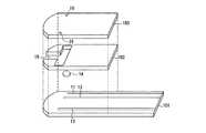
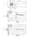
図1、図2および図3に、本発明の血液成分測定用センサの一例を示す。図1は、前記センサの分解斜視図であり、図2は断面図であり、図3は平面図であり、前記三図において、同一部分には同一符号を付している。 1, 2 and 3 show an example of the blood component measurement sensor of the present invention. FIG. 1 is an exploded perspective view of the sensor, FIG. 2 is a cross-sectional view, FIG. 3 is a plan view, and the same parts in FIG.
図示のように、このセンサは、絶縁基板101の上に、3個の電極11、12および13が形成されている。これらの電極は、作用極と対極に切り換え可能である。電極13の表面は、CMC等の高分子材料で被覆されている。電極11および12が形成する電極部には試薬層14が配置されている。試薬層14は、グルコースデヒドロゲナーゼ等の酸化還元酵素、メディエータを含み、任意成分として、高分子材料、酵素安定化剤、結晶均質化剤を含む。これらの試薬の種類や配合割合は、前述のとおりである。前記絶縁基板101の上には、一方の端部(図において右側端部)を残してスペーサー102を介しカバー103が配置されている。このセンサには、電極13および電極11、12に血液を導入するための流路15が形成されている。この流路15は、途中から分岐したT字形状であり、各分岐端は、前記各電極部に連通しており、また前記流路の先端は、センサの他方の端部(図において左側端部)まで延びており、外部に対し開口して、血液供給口となっている。前記の3個の電極11、12および13は、それぞれリードと連結し、これらのリードは、前記一方の端部側に延びており、リードの先端はカバーに覆われずに露出している。前記カバー103の流路15の分岐端に対応する部分には、2つの空気抜孔16が形成されている。 As shown in the figure, this sensor has three
本発明において、前記絶縁基板の材質は特に制限されず、例えば、ポリエチレンテレフタレート(PET)、ポリカーボネート(PC)、ポリイミド(PI)、ポリエチレン(PE)、ポリプロピレン(PP)、ポリスチレン(PS)、ポリ塩化ビニル(PVC)、ポリオキシメチレン(POM)、モノマーキャストナイロン(MC)、ポリブチレンテレフタレート(PBT)、メタクリル樹脂(PMMA)、ABS樹脂(ABS)、ガラス等が使用でき、このなかで、ポリエチレンテレフタレート(PET)、ポリカーボネート(PC)、ポリイミド(PI)が好ましく、より好ましくは、ポリエチレンテレフタレート(PET)である。絶縁基板の大きさは、特に制限されず、例えば、全長5〜100mm、幅2〜50mm、厚み0.05〜2mmであり、好ましくは、全長7〜50mm、幅3〜20mm、厚み0.1〜1mmであり、より好ましくは、全長10〜30mm、幅3〜10mm、厚み0.1〜0.6mmである。 In the present invention, the material of the insulating substrate is not particularly limited. For example, polyethylene terephthalate (PET), polycarbonate (PC), polyimide (PI), polyethylene (PE), polypropylene (PP), polystyrene (PS), polychlorinated Vinyl (PVC), polyoxymethylene (POM), monomer cast nylon (MC), polybutylene terephthalate (PBT), methacrylic resin (PMMA), ABS resin (ABS), glass, etc. can be used. Among these, polyethylene terephthalate (PET), polycarbonate (PC), and polyimide (PI) are preferable, and polyethylene terephthalate (PET) is more preferable. The size of the insulating substrate is not particularly limited, and is, for example, a total length of 5 to 100 mm, a width of 2 to 50 mm, and a thickness of 0.05 to 2 mm, preferably a total length of 7 to 50 mm, a width of 3 to 20 mm, and a thickness of 0.1. More preferably, the total length is 10 to 30 mm, the width is 3 to 10 mm, and the thickness is 0.1 to 0.6 mm.
絶縁基板上の電極およびリードは、例えば、金、白金、パラジウム等を材料として、スパッタリング法あるいは蒸着法により導電層を形成し、これをレーザーにより特定の電極パターンに加工することで形成できる。レーザーとしては、例えば、YAGレーザー、CO2レーザー、エキシマレーザー等が使用できる。なお、電極パターンについては、実施例等に開示されたもののみには限定されず、本発明における効果を実現できるものであれば、電極パターンに制限はない。電極13の表面の被覆は、例えば、高分子材料の溶液を調製し、これを前記電極表面に滴下若しくは塗布し、ついで乾燥させることにより実施できる。乾燥は、例えば、自然乾燥、風乾、熱風乾燥、加熱乾燥などがある。 The electrodes and leads on the insulating substrate can be formed, for example, by forming a conductive layer by sputtering or vapor deposition using gold, platinum, palladium or the like as a material, and processing this into a specific electrode pattern by laser. As the laser, for example, a YAG laser, a CO2 laser, an excimer laser or the like can be used. In addition, about an electrode pattern, it is not limited only to what was disclosed by the Example etc., If an effect in this invention is realizable, there will be no restriction | limiting in an electrode pattern. The surface of the
前記試薬部14は、例えば、0.01〜2.0wt%CMC水溶液に、PQQ−GDHを0.1〜5.0U/センサ、フェリシアン化カリウムを10〜200mM、マルチトールを1〜50mM、タウリンを20〜200mM添加して溶解させて試薬溶液を調製し、これを、前記基板の電極11および12の上に滴下し、乾燥させることで形成できる。前記乾燥は、例えば、自然乾燥でも温風を用いた強制乾燥でもよいが、高温過ぎると酵素が失活するおそれがあるから、50℃前後の温風が好ましい。 The
つぎに、本発明において、スペーサーの材質は、特に制限されず、例えば、前記絶縁基板と同様の材料が使用できる。また、スペーサーの大きさは、特に制限されず、例えば、全長5〜100mm、幅2〜50mm、厚み0.01〜1mmであり、好ましくは、全長7〜50mm、幅3〜20mm、厚み0.05〜0.5mmであり、より好ましくは、全長10〜30mm、幅3〜10mm、厚み0.05〜0.25mmである。スペーサーには、血液導入のための流路となるT字形状の切り欠き部が形成されているが、その大きさは、例えば、血液供給口から分岐部までの長さ0.5〜20mm、分岐部から分岐端までの長さ1〜25mm、幅0.1〜5mm、好ましくは、血液供給口から分岐部までの長さ1〜10mm、分岐部から分岐端までの長さ1.5〜10mm、幅0.2〜3mm、より好ましくは、血液供給口から分岐部までの長さ1〜5mm、分岐部から分岐端までの長さ1.5〜5mm、幅0.5〜2mmである。この切り欠き部は、例えば、レーザーやドリル等で穿孔して形成してもよいし、スペーサーの形成時に、切り欠き部が形成できるような金型を使用して形成してもよい。 Next, in the present invention, the material of the spacer is not particularly limited, and for example, the same material as that of the insulating substrate can be used. The size of the spacer is not particularly limited, and is, for example, 5 to 100 mm in length, 2 to 50 mm in width, and 0.01 to 1 mm in thickness, and preferably 7 to 50 mm in length, 3 to 20 mm in width, and 0. More preferably, the total length is 10 to 30 mm, the width is 3 to 10 mm, and the thickness is 0.05 to 0.25 mm. The spacer is formed with a T-shaped notch that serves as a flow path for blood introduction. The size of the spacer is, for example, a length of 0.5 to 20 mm from the blood supply port to the branch portion, 1 to 25 mm in length from the branch part to the branch end, 0.1 to 5 mm in width, preferably 1 to 10 mm in length from the blood supply port to the branch part, 1.5 to 1.5 mm in length from the branch part to the branch end 10 mm, width 0.2 to 3 mm, more preferably 1 to 5 mm from the blood supply port to the branch, 1.5 to 5 mm from the branch to the branch end, and 0.5 to 2 mm . This notch may be formed by, for example, drilling with a laser, a drill, or the like, or may be formed by using a mold that can form the notch when the spacer is formed.
つぎに、本発明において、カバーの材質は、特に制限されず、例えば、前記絶縁基板と同様の材料が使用できる。カバーの試料供給路の天井部に相当する部分は、親水性処理することが、更に好ましい。親水性処理としては、例えば、界面活性剤を塗布する方法、プラズマ処理などによりカバー表面に水酸基、カルボニル基、カルボキシル基などの親水性官能基を導入する方法がある。カバーの大きさは、特に制限されず、例えば、全長5〜100mm、幅3〜50mm、厚み0.01〜0.5mmであり、好ましくは、全長10〜50mm、幅3〜20mm、厚み0.05〜0.25mmであり、より好ましくは、全長15〜30mm、幅5〜10mm、厚み0.05〜0.2mmである。カバーには、空気抜孔が形成されていることが好ましく、形状は、例えば、円形、楕円形、多角形などであり、その大きさは、例えば、最大直径0.01〜10mm、好ましくは、最大直径0.025〜5mm、より好ましくは、最大直径0.025〜2mmである。また、空気抜孔を複数個設けてもかまわない。この空気抜孔は、例えば、レーザーやドリル等で穿孔して形成してもよいし、カバーの形成時に、空気抜き部が形成できるような金型を使用して形成してもよい。つぎに、このセンサは、絶縁基板、スペーサーおよびカバーをこの順序で積層し、一体化することにより製造できる。一体化には、前記3つの部材を接着剤で貼り付けたり、若しくは熱融着してもよい。前記接着剤としては、例えば、エポキシ系接着剤、アクリル系接着剤、ポリウレタン系接着剤、また熱硬化性接着剤(ホットメルト接着剤等)、UV硬化性接着剤等が使用できる。 Next, in the present invention, the material of the cover is not particularly limited, and for example, the same material as that of the insulating substrate can be used. More preferably, the portion of the cover corresponding to the ceiling of the sample supply path is hydrophilically treated. Examples of the hydrophilic treatment include a method of applying a surfactant and a method of introducing a hydrophilic functional group such as a hydroxyl group, a carbonyl group, or a carboxyl group into the cover surface by plasma treatment or the like. The size of the cover is not particularly limited, and is, for example, a total length of 5 to 100 mm, a width of 3 to 50 mm, and a thickness of 0.01 to 0.5 mm, and preferably a total length of 10 to 50 mm, a width of 3 to 20 mm, and a thickness of 0. It is 05-0.25 mm, More preferably, it is full length 15-30 mm, width 5-10 mm, and thickness 0.05-0.2 mm. The cover is preferably formed with an air vent, and the shape is, for example, a circle, an ellipse, or a polygon, and the size is, for example, a maximum diameter of 0.01 to 10 mm, preferably a maximum. The diameter is 0.025 to 5 mm, and more preferably the maximum diameter is 0.025 to 2 mm. A plurality of air vent holes may be provided. The air vent hole may be formed by, for example, drilling with a laser or a drill, or may be formed using a mold that can form an air vent portion when the cover is formed. Next, this sensor can be manufactured by stacking and integrating the insulating substrate, the spacer, and the cover in this order. For the integration, the three members may be attached with an adhesive or heat-sealed. Examples of the adhesive include epoxy adhesives, acrylic adhesives, polyurethane adhesives, thermosetting adhesives (hot melt adhesives, etc.), UV curable adhesives, and the like.
このセンサを用いた血糖値測定は、例えば、次のようにして実施される。すなわち、まず、専用のランセットで指先等を穿刺し、出血させる。一方、前記センサを専用の測定装置(メータ)にセットする。そして、出血した血液に、測定装置にセットしたセンサの血液供給口を接触させ、毛細管現象により、血液をセンサ内部に導入させる。そして、このセンサによる分析は、つぎのステップにより行われる。 For example, blood glucose level measurement using this sensor is performed as follows. That is, first, a fingertip or the like is punctured with a dedicated lancet to cause bleeding. On the other hand, the sensor is set in a dedicated measuring device (meter). Then, the blood supply port of the sensor set in the measuring device is brought into contact with the bleeding blood, and blood is introduced into the sensor by capillary action. The analysis by this sensor is performed by the following steps.
(ステップ1:検体(血液)の検知)
電極11、電極13の両電極間に電圧を印加し、血液の導入に伴う電流値の変化により血液の導入を検知する。血液の導入を確認したら、以降のステップを開始する。ステップ1での印加電圧は、例えば、0.05〜1Vである。(Step 1: Detection of specimen (blood))
A voltage is applied between the
(ステップ2:グルコースの測定)
血液中のグルコースとグルコース酸化還元酵素とを一定時間反応させた後、電極11を作用極、電極12を対極とし、前記両電極に電圧を印加し、酵素反応により電極11の上に生じた還元状態のメディエータを酸化し、その酸化電流を検出する。前記グルコースと酸化還元酵素との反応時間は、例えば、0〜60秒、好ましくは0.5〜30秒、より好ましくは1〜10秒である。ステップ2での印加電圧および印加時間は、例えば、0.05〜1V、好ましくは0.1〜0.8V、より好ましくは0.2〜0.5Vであり、印加時間は、例えば、0.01〜30秒、好ましくは0.1〜10秒、より好ましくは1〜5秒である。(Step 2: Measurement of glucose)
After glucose in the blood reacts with glucose oxidoreductase for a certain period of time,
(ステップ3:Hct値の測定)
電極13を作用極、電極11を対極として、前記両電極に電圧を印加することにより、血液成分の電解酸化反応に基づくHct値に依存する電流が検出することができる。なお、検出した電流からHct値への換算は、予め検量線または検量線テーブルを求めておくことにより行うことができる。この補正では、予め作成された電流とHct値との検量線から求めたHct値を使用してもよいし、検出された電流をそのまま使用してもよい。ステップ3での印加電圧および印加時間は、例えば、1〜10V、好ましくは1〜6.5V、より好ましくは2〜3Vであり、印加時間は、例えば、0.001〜60秒、好ましくは0.01〜10秒、より好ましくは0.01〜5秒である。このステップにおいて、作用極である電極13にはメディエータが配置されず、かつ電極13と電極11との間は一定の間隙があり、この間隙にはメディエータなど試薬が配置されておらず血液のみ存在するので、試薬の影響を受けることなくHct値に依存した酸化電流が検出できる。このステップ3は、ステップ2の終了後に実施されることが好ましい。また、対極は、この例では電極11としたが、電極12を対極としても測定は可能である。電極11および12の双方を対極としてもよい。なお、電極13の表面に高分子材料等による被覆をしない場合においても、測定は可能である。(Step 3: Hct value measurement)
By applying a voltage to both electrodes with the
(ステップ4:血液成分の補正)
ステップ3で検出したHct値により、ステップ2で得られたグルコース量を補正する。この補正は、予め作成した検量線(検量テーブルを含む)に基づき行うことが好ましい。補正されたグルコース量は、測定装置に表示若しくは記憶される。なお、上述のように一旦、Hct値を求めてからグルコース量を補正するのではなく、ステップ3にて検出したHct値に依存した電流をそのまま用いてグルコース量を補正してもよい。(Step 4: correction of blood components)
Based on the Hct value detected in
図4、図5および図6に、本発明の血液成分測定用センサのその他の例を示す。図4は、前記センサの分解斜視図であり、図5は断面図であり、図6は平面図であり、前記三図において、同一部分には同一符号を付している。 4, 5 and 6 show other examples of the blood component measurement sensor of the present invention. 4 is an exploded perspective view of the sensor, FIG. 5 is a cross-sectional view, FIG. 6 is a plan view, and the same parts in FIG.
図示のように、このセンサは、絶縁基板201の上に、4個の電極21、22、23および24が形成されている。これらの電極は、作用極と対極に切り換え可能である。電極24の表面は、前述のようにして高分子材料で被覆されている。電極21、22および23が形成する電極部には試薬層25が配置されている。試薬層25は、グルコースデヒドロゲナーゼ等の酸化還元酵素、メディエータを含み、任意成分として、高分子材料、酵素安定化剤、結晶均質化剤を含む。これらの試薬の種類や配合割合は、前述のとおりである。前記絶縁基板201の上には、一方の端部(図において右側端部)を残してスペーサー202を介しカバー203が配置されている。このセンサには、前記試薬部25に血液を導入するための流路26が形成されている。この流路26は、一直線(I字形状)であり、また前記流路の先端は、センサの他方の端部(図において左側端部)まで延びており、外部に対し開口して、血液供給口となっている。前記4個の電極は、前記流路に直列に並んでおり、血液供給口側から、電極22は最も後方に位置している。前記の4個の電極21、22、23および24は、それぞれリードと連結し、これらのリードは、前記一方の端部側に延びており、リードの先端はカバーに覆われずに露出している。前記カバー203の流路26の後方に対応する部分には、空気抜孔27が形成されている。 As shown in the figure, this sensor has four
この例において、前記絶縁基板の材質および大きさ等は、特に制限されず、実施例1と同様である。また、電極、リード、高分子材料による電極表面の被覆および試薬部も実施例1と同様である。そして、スペーサーの材質、大きさおよび加工方法も実施例1と同様である。この例のスペーサーには、血液導入のための流路となるI字形状の切り欠き部が形成されているが、その大きさは、例えば、全長0.5〜50mm、幅0.1〜5mm、好ましくは、全長1〜10mm、幅0.2〜3mm、より好ましくは、全長1〜5mm、幅0.5〜2mmである。この切り欠き部は、例えば、レーザーやドリル等で穿孔して形成してもよいし、スペーサーの形成時に、切り欠き部が形成できるような金型を使用して形成してもよい。カバーの材質、大きさ、親水性処理および空気抜き孔も、実施例1と同様である。そして、この例のセンサの製造方法も実施例1と同様である。 In this example, the material and size of the insulating substrate are not particularly limited, and are the same as those in the first embodiment. The electrode, lead, electrode surface coating with a polymer material, and the reagent part are the same as in Example 1. The spacer material, size, and processing method are the same as those in the first embodiment. The spacer of this example is formed with an I-shaped notch that serves as a flow path for blood introduction. The size of the spacer is, for example, 0.5 to 50 mm in length and 0.1 to 5 mm in width. The total length is preferably 1 to 10 mm and the width is 0.2 to 3 mm, and more preferably the total length is 1 to 5 mm and the width is 0.5 to 2 mm. This notch may be formed by, for example, drilling with a laser, a drill, or the like, or may be formed by using a mold that can form the notch when the spacer is formed. The cover material, size, hydrophilic treatment and air vent holes are the same as in the first embodiment. The manufacturing method of the sensor of this example is the same as that of the first embodiment.
このセンサを用いた血糖値測定は、例えば、次のようにして実施される。すなわち、まず、専用のランセットで指先等を穿刺し、出血させる。一方、前記センサを専用の測定装置(メータ)にセットする。そして、出血した血液に、測定装置にセットしたセンサの血液供給口を接触させ、毛細管現象により、血液をセンサ内部に導入させる。そして、このセンサによる分析は、つぎのステップにより行われる。 For example, blood glucose level measurement using this sensor is performed as follows. That is, first, a fingertip or the like is punctured with a dedicated lancet to cause bleeding. On the other hand, the sensor is set in a dedicated measuring device (meter). Then, the blood supply port of the sensor set in the measuring device is brought into contact with the bleeding blood, and blood is introduced into the sensor by capillary action. The analysis by this sensor is performed by the following steps.
(ステップ1:検体(血液)の検知)
電極24、電極22の両電極間に電圧を印加することにより、血液が、流路の端まで導入されたかを検知する。血液が流路の端まで導入されたことを確認したら、以降のステップを開始する。また、流路の端まで導入されない場合は、検体量不足となり、測定装置はエラーを表示することになる。ステップ1での印加電圧は、例えば、0.05〜1Vである。なおこの場合、電極22とそれ以外のいずれかの電極(21、23、24)間における電流変化を検知することで、検体の検知が可能である。(Step 1: Detection of specimen (blood))
By applying a voltage between the
(ステップ2:グルコースの測定)
血液中のグルコースとグルコース酸化還元酵素とを一定時間反応させた後、電極21を作用極、電極23を対極として、前記両電極に電圧を印加し、酵素反応により電極21の上に生じた還元状態のメディエータを酸化し、その酸化電流を検出する。前記グルコースと酸化還元酵素との反応時間は、例えば、0〜60秒、好ましくは0.5〜30秒、より好ましくは1〜10秒である。ステップ2での印加電圧および印加時間は、例えば、0.05〜1V、好ましくは0.1〜0.8V、より好ましくは0.2〜0.5Vであり、印加時間は、例えば、0.01〜30秒、好ましくは0.1〜10秒、より好ましくは1〜5秒である。(Step 2: Measurement of glucose)
After reacting glucose in the blood with glucose oxidoreductase for a certain period of time, the
(ステップ3:Hct値の測定)
電極24を作用極、電極21を対極として、前記両電極に電圧を印加することにより、Hct値に依存する電流が検出でき、これに基づきHct値を測定する。このHct値は、グルコース測定時の補正に使用される。この補正では、予め作成された電流とHct値との検量線から求めたHct値を使用してもよいし、検出された電流をそのまま使用してもよい。ステップ3での印加電圧および印加時間は、例えば、1〜10V、好ましくは1〜6.5V、より好ましくは2〜3Vであり、印加時間は、例えば、0.001〜60秒、好ましくは0.01〜10秒、より好ましくは0.01〜5秒である。このステップにおいて、作用極である電極24にはメディエータが配置されておらず、かつ電極24と電極21との間は一定の間隙があり、この間隙にはメディエータなど試薬が配置されておらず血液のみ存在するので、試薬の影響を受けることなくHct値に依存した酸化電流が検出できる。このステップ3は、ステップ2の終了後に実施されることが好ましい。なお、この例では、電極21単独で対極としたが、本発明はこれには限定されず、電極23単独、電極22単独、電極21と電極22の組み合わせ、電極21と電極23の組み合わせ、電極22と電極23の組み合わせ、電極21と電極22と電極23の組み合わせを、それぞれ対極としてもよい。また、電極13の表面に高分子材料等による被覆をしない場合においても、測定は可能である。(Step 3: Hct value measurement)
By applying a voltage to both electrodes with the
(ステップ4:血液成分の補正)
ステップ3で検出したHct値により、ステップ2で得られたグルコース量を補正する。この補正は、予め作成した検量線(検量テーブルを含む)に基づき行うことが好ましい。補正されたグルコース量は、測定装置に表示若しくは記憶される。(Step 4: correction of blood components)
Based on the Hct value detected in
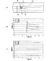
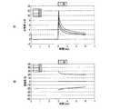
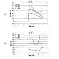
本実施例では、6種類のセンサ(3−1〜3−6)を作製し、それぞれのセンサにおいて、Hct測定における作用極もしくは対極に対するメディエータを含む試薬層の配置を変えて、応答電流および感度差を測定した。また、併せて、比較例1として、3種類のセンサ(3−7〜3−9)を作製し、それぞれのセンサにおいて、Hct測定における作用極もしくは対極に対するメディエータを含む試薬層の配置を変えて、応答電流および感度差を測定した。なお、検体(血液)およびグルコースの測定、ならびに血液成分の補正は、実施例2と同様にして行った。前記各センサは、試薬層の配置以外は、基本的には実施例2と同様にして作製した。なお、試薬層は、フェリシアン化カリウム(量:60mM)、タウリン(80mM)を、CMC水溶液(0.1wt%)に溶解して調製した試薬液を、電極上に滴下した後、乾燥させて作製した。作用極および対極の間の距離は、0.1mm以上とした。また、Hct値を、25、45および65に調整した、3種類の血液試料を準備した。これら3つの血液試料について、前記各センサにより、印加電圧2.5V、印加時間3秒の条件で、前記各センサの前記両電極に流れる電流を測定し、Hct値の測定における応答電流値および感度差の測定をおこなった。以下、前記各センサの試薬層の配置パターンと、前記測定結果を、図7〜図15に示す。なお、図7〜図15において、図Aは、試薬層25の配置パターンを示す図であり、図Bは、印加電圧(V)に対する応答電流値(μA)の経時的変化を表すグラフであり、図Cは、印加電圧(V)に対する感度差(%)の経時変化のグラフであり、図4〜6と同一部分には同一符号を付している。 In this example, six types of sensors (3-1 to 3-6) were produced, and in each sensor, the arrangement of the reagent layer including the mediator with respect to the working electrode or the counter electrode in the Hct measurement was changed, and the response current and sensitivity were changed. The difference was measured. In addition, as Comparative Example 1, three types of sensors (3-7 to 3-9) were prepared, and in each sensor, the arrangement of the reagent layer including the mediator for the working electrode or the counter electrode in the Hct measurement was changed. The response current and sensitivity difference were measured. The measurement of the specimen (blood) and glucose and the correction of blood components were performed in the same manner as in Example 2. Each of the sensors was basically manufactured in the same manner as in Example 2 except for the arrangement of the reagent layer. The reagent layer was prepared by dropping a reagent solution prepared by dissolving potassium ferricyanide (amount: 60 mM) and taurine (80 mM) in a CMC aqueous solution (0.1 wt%) on the electrode and then drying it. . The distance between the working electrode and the counter electrode was 0.1 mm or more. In addition, three types of blood samples with Hct values adjusted to 25, 45 and 65 were prepared. With respect to these three blood samples, the currents flowing through the electrodes of the sensors are measured by the sensors under the conditions of an applied voltage of 2.5 V and an applied time of 3 seconds. The difference was measured. Hereinafter, the arrangement pattern of the reagent layer of each sensor and the measurement result are shown in FIGS. 7 to 15, FIG. A is a diagram showing an arrangement pattern of the
(3−1)
図7Aに示すように、この例のセンサでは、試薬層25を、Hct測定用の対極21からはみ出るように配置しており、対極21表面上と、前記血液成分測定用の両電極間の対極側の一部とに、試薬層25が存在している。このセンサの前記両電極に流れる電流を測定した結果を、図7Bおよび図7Cのグラフに示す。前記両図に示すように、このセンサによれば、その感度差が電圧印加時間に依存せず、Hct値を反映した応答電流を明確かつ良好に検出することができた。(3-1)
As shown in FIG. 7A, in the sensor of this example, the
(3−2)
図8Aに示すように、この例のセンサでは、試薬層25を、対極21の表面上のみに配置している。このセンサの作用極24および対極21に流れる電流を測定した結果を、図8Bおよび図8Cのグラフに示す。前記両図に示すように、このセンサによれば、その感度差が電圧印加時間に依存せず、Hct値を反映した応答電流を明確かつ良好に検出することができた。(3-2)
As shown in FIG. 8A, in the sensor of this example, the
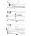
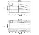
(3−3)
図9Aに示すように、この例のセンサでは、試薬層25を、対極21からはみ出るように配置しており、対極21表面上と、前記両電極間とに、試薬層25が存在している。なお、作用極24上には酸化還元物質は存在していない。このセンサの前記両電極に流れる電流を測定した結果を、図9Bおよび図9Cのグラフに示す。前記両図に示すように、このセンサによれば、その感度差が電圧印加時間に依存せず、Hct値を反映した応答電流を明確に検出することができた。(3-3)
As shown in FIG. 9A, in the sensor of this example, the
(3−4)
図10Aに示すように、この例のセンサでは、Hct測定用の作用極24と対極21の配置を入れ替えており、試薬層25は、対極21表面上と、前記血液成分測定用の両電極間の対極側の一部に形成している。このセンサの前記両電極に流れる電流を測定した結果を、図10Bおよび図10Cのグラフに示す。前記両図に示すように、このセンサによれば、その感度差が電圧印加時間に依存せず、Hct値を反映した応答電流を明確に検出することができたが、上記(3−1)、(3−2)、(3−3)の例に比べると、感度差が若干小さかった。(3-4)
As shown in FIG. 10A, in the sensor of this example, the arrangement of the working
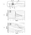
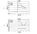
(3−5)
図11Aに示すように、この例のセンサでは、試薬層25を、対極21からはみ出るように配置しており、対極21表面の一部上と、前記両電極間の一部とに、試薬層25が存在している。このセンサの前記両電極に流れる電流を測定した結果を、図11Bおよび図11Cのグラフに示す。前記両図に示すように、このセンサによれば、電圧を印加した直後の1秒間(図中3〜4秒の間)においては、Hct値を反映した応答電流を明確に検出することができた。(3-5)
As shown in FIG. 11A, in the sensor of this example, the
(3−6)
図12Aに示すように、この例のセンサでは、試薬層25を、対極21からはみ出るように配置しており、対極21表面の一部に、試薬層25が存在している。なお、前記両電極間には、酸化還元物質は存在していない。このセンサの前記両電極に流れる電流を測定した結果を、図12Bおよび図12Cのグラフに示す。前記両図に示すように、このセンサによれば、電圧を印加した直後の1秒間(図中3〜4秒の間)においては、Hct値を反映した応答電流を明確に検出することができた。(3-6)
As shown in FIG. 12A, in the sensor of this example, the
(3−7)
図13Aに示すように、この比較例のセンサでは、試薬層25を、作用極24、対極21および前記両電極間の全てに配置している。このセンサの前記両電極間に流れる電流を測定した結果を、図13Bおよび図13Cのグラフに示す。前記両図に示すように、このセンサでは、Hct値を反映した応答電流を明確に検出できなかった。(3-7)
As shown in FIG. 13A, in the sensor of this comparative example, the
(3−8)
図14Aに示すように、この比較例のセンサでは、試薬層25を、作用極24および対極21のそれぞれ配置しており、前記両電極間の一部にも試薬層25が位置している。このセンサの前記両電極に流れる電流を測定した結果を、図14Bおよび図14Cのグラフに示す。前記両図に示すように、このセンサでは、Hct値を反映した応答電流を明確に検出できなかった。(3-8)
As shown in FIG. 14A, in the sensor of this comparative example, the
(3−9)
図15Aに示すように、この比較例のセンサでは、試薬層25を配置していない。このセンサの前記両電極に流れる電流を測定した結果を、図15Bおよび図15Cのグラフに示す。前記両図に示すように、このセンサでは、Hct値を反映した応答電流を検出できなかった。(3-9)
As shown in FIG. 15A, the
本実施例では、印加電圧を0.5〜6.5Vの範囲で変化させて、Hct測定における応答電流および感度差を測定した。検体(血液)およびグルコースの測定、ならびに血液成分の補正は、実施例2と同様にして行った。この測定に使用したセンサは、実施例3と同様にして作製した。なお、試薬層25は、対極21上に配置し、作用極24には配置しなかった(図7A参照)。また、応答電流値および感度差の測定も、実施例3と同様にして行った。この測定結果を、図16〜図28の各グラフに示す。なお、図16〜図28において、図Aは、印加電圧(V)に対する応答電流値(μA)の経時的変化を表すグラフであり、図Bは、印加電圧(V)に対する感度差(%)の経時変化のグラフである。 In this example, the applied current was changed in the range of 0.5 to 6.5 V, and the response current and sensitivity difference in the Hct measurement were measured. Measurement of the specimen (blood) and glucose, and correction of blood components were performed in the same manner as in Example 2. The sensor used for this measurement was produced in the same manner as in Example 3. In addition, the
図16に示すように、0.5Vの印加電圧であってもHct値を反映した応答電流を検出できたが、1〜6.5Vで印加すると、図17〜図28に示すように、さら明確に応答電流が検出可能であり、最も好ましいのは、図17〜図21に示すように、1〜3Vで印加した場合であった。なお、5V以上で印加すると、時間の経過により波形が乱れるが、印加直後から短い時間内であれば、Hct値を反映した応答電流を明確に検出できる。なお、本実施例では、一定の条件下で印加電圧を変化させてHct値に基づく電流を検出したが、本発明は、これに限定されず、印加電圧が本実施例で示した範囲に無くても、電極間距離、酸化還元物質の種類や量等のその他の条件を適宜設定することで、Hct値を反映した応答電流を明確に検出することが可能であり、これに基づき血液成分量を補正できる。 As shown in FIG. 16, a response current reflecting the Hct value could be detected even with an applied voltage of 0.5 V, but when applied at 1 to 6.5 V, as shown in FIGS. The response current can be clearly detected, and the most preferable case is when the voltage is applied at 1 to 3 V as shown in FIGS. When applied at 5 V or higher, the waveform is disturbed over time, but the response current reflecting the Hct value can be clearly detected within a short time immediately after application. In this embodiment, the current based on the Hct value is detected by changing the applied voltage under a certain condition. However, the present invention is not limited to this, and the applied voltage is not in the range shown in this embodiment. However, it is possible to clearly detect the response current reflecting the Hct value by appropriately setting other conditions such as the distance between the electrodes and the type and amount of the redox substance, and based on this, the blood component amount Can be corrected.
図30の平面図に、本発明のセンサのさらにその他の例を示す。このセンサは、前記実施例1〜4で示したセンサの電極パターンとは、異なる電極パターンを有する。図示のように、このセンサは、絶縁基板の上において、血液の流れの上流側に、Hct測定用の第2の分析部を構成する2つの電極111、112を有し、さらに、下流側に、血液成分測定用の第1の分析部を構成する2つの電極113、114を有する。このセンサにおいて、第1の分析部と第2の分析部のそれぞれに試薬層(図示せず)が配置される。第1の分析部に配置される試薬層は、グルコースデヒドロゲナーゼ等の酸化還元酵素、メディエータを含み、任意成分として、高分子材料、酵素安定化剤、結晶均質化剤を含み、その配置は特に制限されない。一方、第2の分析部に配置される試薬層は、メディエータを含み、任意成分として高分子材料を含む。第2の分析部において、試薬層は、対極のみに配置される。これら以外については、実施例1もしくは2に例示したセンサと同様である。 The plan view of FIG. 30 shows still another example of the sensor of the present invention. This sensor has an electrode pattern different from the electrode pattern of the sensor shown in the first to fourth embodiments. As shown in the figure, this sensor has two
つぎに、図31に本発明の測定装置の構成の一例を示す。この測定装置は、例えば、実施例2で示したセンサが装着可能である。図示のように、この測定装置130は、4つのコネクタ137a〜137d、切換回路136、電流/電圧変換回路135、A/D変換回路134、基準電圧源133、CPU131、および液晶表示装置(LCD)132を主要構成要素としている。なお、基準電圧源133は、グランドとしてもよい。センサの各電極21、22、23、24は、コネクタ137a〜137d、および切換回路136を介して電流/電圧変換回路135と基準電圧源133とに接続されている。電流/電圧変換回路135は、A/D変換回路134を介してCPU131に接続されている。 Next, FIG. 31 shows an example of the configuration of the measuring apparatus of the present invention. For example, the sensor shown in Example 2 can be attached to this measuring apparatus. As shown in the figure, this measuring
この測定装置において、血液成分量の測定は、例えば、次のようにして実施される。 In this measuring apparatus, the blood component amount is measured, for example, as follows.
まずCPU131の指令により、切換回路136により、血液成分量を測定するための作用極となる電極21がコネクタ137aを介して電流/電圧変換回路135に接続され、血液の導入を検地するための検知極となる電極22がコネクタ137bを介して基準電圧源133に接続される。CPU131の指令により電流/電圧変換回路135および基準電圧源133から、電極21および電極22間に一定の電圧が印加され、血液が導入されると、電極21、22間に電流が流れる。この電流は、電流/電圧変換回路135によって電圧に変換され、その電圧値は、A/D変換回路134によってデジタル値に変換されて、CPU131に出力される。CPU131はそのデジタル値をもとに血液が導入されたことを検出する。 First, in response to a command from the
血液が導入されたことを検知後、血液成分量の測定がおこなわれる。血液成分量の測定は次のようにして実施される。まずCPU131の指令により、切換回路136により血液成分量の測定のための作用極となる電極21がコネクタ137aを介して電流/電圧変換回路135に接続され、血液成分量の測定のための対極となる電極23がコネクタ137cを介して基準電圧源133に接続される。 After detecting that blood has been introduced, the amount of blood components is measured. The measurement of the amount of blood components is performed as follows. First, in response to a command from the
なお、例えば血液中グルコースとその酸化還元酵素とを一定時間反応させる間は、電流/電圧変換回路135および基準電圧源133をオフしておき、一定時間の経過後に、CPU131の指令により、上記電極21と23間に一定の電圧を印加する。電極21、23間に電流が流れ、この電流は、電流/電圧変換回路135によって電圧に変換され、その電圧値は、A/D変換回路134によって、デジタル値に変換されてCPU131に出力される。CPU131はそのデジタル値をもとに血液成分量に換算する。 For example, the current /
血液成分量の測定後、Hct値の測定がおこなわれる。Hct値の測定は例えば次のようにしておこなわれる。まず、CPU131の指令により、切換回路136によりHct値の測定のための作用極となる電極24がコネクタ137dを介して電流/電圧変換回路135に接続され、Hct値の測定のための対極となる電極21が基準電圧源133に接続される。 After the blood component amount is measured, the Hct value is measured. The Hct value is measured as follows, for example. First, in response to a command from the
CPU131の指令により、電流/電圧変換回路135および基準電圧源133から電極24と21間に一定の電圧が印加される。電極24と21間に流れる電流は、電流/電圧変換回路135によって電圧に変換され、その電圧値は、A/D変換回路134によって、デジタル値に変換されてCPU131に出力される。CPU131はそのデジタル値をもとにHct値に換算する。 A constant voltage is applied between the
上記の測定で得られたHct値と血液成分量を用い、予め求めておいた検量線または検量線テーブルを参照して、血液成分量をHct値で補正し、その補正された結果をLCD132に表示する。 Using the Hct value and blood component amount obtained in the above measurement, referring to a calibration curve or a calibration curve table obtained in advance, the blood component amount is corrected with the Hct value, and the corrected result is displayed on the
以上、グルコースを測定する実施例を示し本発明を説明したが、本発明は、それに限定されるものではない。既に述べたが、本発明は、乳酸、コレステロールのような他の血液成分の測定にも有用である。また、本発明の測定方法およびセンサは、センサに導入される試料の種類に応じた電流応答が得られることから、その結果に基づき、試料の種類を判別することもできる。したがって、本発明の測定方法およびセンサは、例えば、センサ較正用の標準液、血漿、および血液の判別も容易に行うことができる。 As mentioned above, although the Example which measures glucose was shown and this invention was demonstrated, this invention is not limited to it. As already described, the present invention is also useful for measuring other blood components such as lactic acid and cholesterol. In addition, since the measurement method and sensor of the present invention can obtain a current response corresponding to the type of sample introduced into the sensor, the type of sample can also be determined based on the result. Therefore, the measurement method and sensor of the present invention can easily discriminate, for example, standard solutions, plasma, and blood for sensor calibration.
以上のように、本発明の血液成分の測定方法およびこれに用いるセンサならびに測定装置は、Hct値を電気化学的に高精度および高信頼度で、しかも簡単に測定することができ、これに基づき血液成分量を補正することができる。したがって、本発明の測定方法およびセンサならびに測定装置は、生物学、生化学および医学等の血液成分を測定するあらゆる分野に好ましく使用でき、特に臨床検査の分野に好適である。 As described above, the blood component measurement method of the present invention and the sensor and measurement apparatus used therefor can electrochemically measure the Hct value electrochemically with high accuracy and high reliability, and based on this. The amount of blood components can be corrected. Therefore, the measuring method, sensor, and measuring apparatus of the present invention can be preferably used in all fields for measuring blood components such as biology, biochemistry, and medicine, and are particularly suitable for the field of clinical examination.
11、12、13、21、22、23、24、81、82、111、112、113、114 電極
14、25、83 試薬部(試薬層)
15、26、84 流路
16、27、85 空気抜孔
101、201、801 絶縁基板
102、202、802 スペーサー
103、203、803 カバー
121 センサ
122 検体供給口
130、123 測定装置
124 表示部
125 装着口
131 CPU
132 LCD
133 基準電圧源
134 A/D変換回路
135 電流/電圧変換回路
136 切換回路
137a、137b、137c、137d コネクタ11, 12, 13, 21, 22, 23, 24, 81, 82, 111, 112, 113, 114
15, 26, 84
132 LCD
133 Reference voltage source 134 A /
Claims (43)
Translated fromJapaneseApplications Claiming Priority (3)
| Application Number | Priority Date | Filing Date | Title |
|---|---|---|---|
| JP2003405480 | 2003-12-04 | ||
| JP2003405480 | 2003-12-04 | ||
| PCT/JP2004/018020WO2005054840A1 (en) | 2003-12-04 | 2004-12-03 | Blood component measuring method, sensor used therefor, and measuring instrument |
Publications (2)
| Publication Number | Publication Date |
|---|---|
| JPWO2005054840A1 JPWO2005054840A1 (en) | 2007-06-28 |
| JP4611208B2true JP4611208B2 (en) | 2011-01-12 |
Family
ID=34650218
Family Applications (1)
| Application Number | Title | Priority Date | Filing Date |
|---|---|---|---|
| JP2005515983AExpired - Fee RelatedJP4611208B2 (en) | 2003-12-04 | 2004-12-03 | Blood component measuring method, sensor and measuring apparatus used therefor |
Country Status (7)
| Country | Link |
|---|---|
| US (6) | US8535497B2 (en) |
| EP (4) | EP3273232A2 (en) |
| JP (1) | JP4611208B2 (en) |
| KR (1) | KR101117332B1 (en) |
| CN (1) | CN100472210C (en) |
| CA (1) | CA2548440C (en) |
| WO (1) | WO2005054840A1 (en) |
Cited By (3)
| Publication number | Priority date | Publication date | Assignee | Title |
|---|---|---|---|---|
| JPWO2012172772A1 (en)* | 2011-06-16 | 2015-02-23 | パナソニックヘルスケア株式会社 | Sensor and sensor system including the same |
| EP3444602A1 (en) | 2017-08-17 | 2019-02-20 | ARKRAY, Inc. | Measuring method and measuring apparatus |
| EP3454057A1 (en) | 2017-08-17 | 2019-03-13 | ARKRAY, Inc. | Measuring method and measuring apparatus |
Families Citing this family (145)
| Publication number | Priority date | Publication date | Assignee | Title |
|---|---|---|---|---|
| US6391005B1 (en) | 1998-03-30 | 2002-05-21 | Agilent Technologies, Inc. | Apparatus and method for penetration with shaft having a sensor for sensing penetration depth |
| US8641644B2 (en) | 2000-11-21 | 2014-02-04 | Sanofi-Aventis Deutschland Gmbh | Blood testing apparatus having a rotatable cartridge with multiple lancing elements and testing means |
| US7981056B2 (en) | 2002-04-19 | 2011-07-19 | Pelikan Technologies, Inc. | Methods and apparatus for lancet actuation |
| US7749174B2 (en) | 2001-06-12 | 2010-07-06 | Pelikan Technologies, Inc. | Method and apparatus for lancet launching device intergrated onto a blood-sampling cartridge |
| US9427532B2 (en) | 2001-06-12 | 2016-08-30 | Sanofi-Aventis Deutschland Gmbh | Tissue penetration device |
| US8337419B2 (en) | 2002-04-19 | 2012-12-25 | Sanofi-Aventis Deutschland Gmbh | Tissue penetration device |
| US9226699B2 (en) | 2002-04-19 | 2016-01-05 | Sanofi-Aventis Deutschland Gmbh | Body fluid sampling module with a continuous compression tissue interface surface |
| US9795747B2 (en) | 2010-06-02 | 2017-10-24 | Sanofi-Aventis Deutschland Gmbh | Methods and apparatus for lancet actuation |
| JP4209767B2 (en) | 2001-06-12 | 2009-01-14 | ペリカン テクノロジーズ インコーポレイテッド | Self-optimized cutting instrument with adaptive means for temporary changes in skin properties |
| US7344507B2 (en) | 2002-04-19 | 2008-03-18 | Pelikan Technologies, Inc. | Method and apparatus for lancet actuation |
| US7041068B2 (en) | 2001-06-12 | 2006-05-09 | Pelikan Technologies, Inc. | Sampling module device and method |
| EP1395185B1 (en) | 2001-06-12 | 2010-10-27 | Pelikan Technologies Inc. | Electric lancet actuator |
| US7331931B2 (en) | 2002-04-19 | 2008-02-19 | Pelikan Technologies, Inc. | Method and apparatus for penetrating tissue |
| US7909778B2 (en) | 2002-04-19 | 2011-03-22 | Pelikan Technologies, Inc. | Method and apparatus for penetrating tissue |
| US7901362B2 (en) | 2002-04-19 | 2011-03-08 | Pelikan Technologies, Inc. | Method and apparatus for penetrating tissue |
| US7708701B2 (en) | 2002-04-19 | 2010-05-04 | Pelikan Technologies, Inc. | Method and apparatus for a multi-use body fluid sampling device |
| US9248267B2 (en) | 2002-04-19 | 2016-02-02 | Sanofi-Aventis Deustchland Gmbh | Tissue penetration device |
| US7297122B2 (en) | 2002-04-19 | 2007-11-20 | Pelikan Technologies, Inc. | Method and apparatus for penetrating tissue |
| US8372016B2 (en) | 2002-04-19 | 2013-02-12 | Sanofi-Aventis Deutschland Gmbh | Method and apparatus for body fluid sampling and analyte sensing |
| US9795334B2 (en) | 2002-04-19 | 2017-10-24 | Sanofi-Aventis Deutschland Gmbh | Method and apparatus for penetrating tissue |
| US7674232B2 (en) | 2002-04-19 | 2010-03-09 | Pelikan Technologies, Inc. | Method and apparatus for penetrating tissue |
| US7232451B2 (en) | 2002-04-19 | 2007-06-19 | Pelikan Technologies, Inc. | Method and apparatus for penetrating tissue |
| US7892183B2 (en) | 2002-04-19 | 2011-02-22 | Pelikan Technologies, Inc. | Method and apparatus for body fluid sampling and analyte sensing |
| US7491178B2 (en) | 2002-04-19 | 2009-02-17 | Pelikan Technologies, Inc. | Method and apparatus for penetrating tissue |
| US8360992B2 (en) | 2002-04-19 | 2013-01-29 | Sanofi-Aventis Deutschland Gmbh | Method and apparatus for penetrating tissue |
| US8702624B2 (en) | 2006-09-29 | 2014-04-22 | Sanofi-Aventis Deutschland Gmbh | Analyte measurement device with a single shot actuator |
| US7976476B2 (en) | 2002-04-19 | 2011-07-12 | Pelikan Technologies, Inc. | Device and method for variable speed lancet |
| US9314194B2 (en) | 2002-04-19 | 2016-04-19 | Sanofi-Aventis Deutschland Gmbh | Tissue penetration device |
| US8267870B2 (en) | 2002-04-19 | 2012-09-18 | Sanofi-Aventis Deutschland Gmbh | Method and apparatus for body fluid sampling with hybrid actuation |
| US8784335B2 (en) | 2002-04-19 | 2014-07-22 | Sanofi-Aventis Deutschland Gmbh | Body fluid sampling device with a capacitive sensor |
| US7229458B2 (en) | 2002-04-19 | 2007-06-12 | Pelikan Technologies, Inc. | Method and apparatus for penetrating tissue |
| US8221334B2 (en) | 2002-04-19 | 2012-07-17 | Sanofi-Aventis Deutschland Gmbh | Method and apparatus for penetrating tissue |
| US8579831B2 (en) | 2002-04-19 | 2013-11-12 | Sanofi-Aventis Deutschland Gmbh | Method and apparatus for penetrating tissue |
| US7547287B2 (en) | 2002-04-19 | 2009-06-16 | Pelikan Technologies, Inc. | Method and apparatus for penetrating tissue |
| US8574895B2 (en) | 2002-12-30 | 2013-11-05 | Sanofi-Aventis Deutschland Gmbh | Method and apparatus using optical techniques to measure analyte levels |
| DE602004028463D1 (en) | 2003-05-30 | 2010-09-16 | Pelikan Technologies Inc | METHOD AND DEVICE FOR INJECTING LIQUID |
| US7850621B2 (en) | 2003-06-06 | 2010-12-14 | Pelikan Technologies, Inc. | Method and apparatus for body fluid sampling and analyte sensing |
| WO2006001797A1 (en) | 2004-06-14 | 2006-01-05 | Pelikan Technologies, Inc. | Low pain penetrating |
| US8282576B2 (en) | 2003-09-29 | 2012-10-09 | Sanofi-Aventis Deutschland Gmbh | Method and apparatus for an improved sample capture device |
| EP1680014A4 (en) | 2003-10-14 | 2009-01-21 | Pelikan Technologies Inc | METHOD AND DEVICE FOR A VARIABLE USER INTERFACE |
| US8007656B2 (en) | 2003-10-24 | 2011-08-30 | Bayer Healthcare Llc | Enzymatic electrochemical biosensor |
| CN100472210C (en) | 2003-12-04 | 2009-03-25 | 松下电器产业株式会社 | Method for measuring blood components and sensor and measuring device used in the method |
| EP1707953B1 (en) | 2003-12-04 | 2015-07-01 | Panasonic Healthcare Holdings Co., Ltd. | Method of measuring hematocrit (Hct) |
| US8668656B2 (en) | 2003-12-31 | 2014-03-11 | Sanofi-Aventis Deutschland Gmbh | Method and apparatus for improving fluidic flow and sample capture |
| US7822454B1 (en) | 2005-01-03 | 2010-10-26 | Pelikan Technologies, Inc. | Fluid sampling device with improved analyte detecting member configuration |
| EP3115777B1 (en)* | 2004-04-19 | 2020-01-08 | PHC Holdings Corporation | Method for measuring blood components |
| MXPA06013233A (en)* | 2004-05-14 | 2007-02-28 | Bayer Healthcare Llc | Methods for performing hematocrit adjustment in glucose assays and devices for same. |
| WO2006011062A2 (en) | 2004-05-20 | 2006-02-02 | Albatros Technologies Gmbh & Co. Kg | Printable hydrogel for biosensors |
| WO2005120365A1 (en) | 2004-06-03 | 2005-12-22 | Pelikan Technologies, Inc. | Method and apparatus for a fluid sampling device |
| US9775553B2 (en) | 2004-06-03 | 2017-10-03 | Sanofi-Aventis Deutschland Gmbh | Method and apparatus for a fluid sampling device |
| US8652831B2 (en) | 2004-12-30 | 2014-02-18 | Sanofi-Aventis Deutschland Gmbh | Method and apparatus for analyte measurement test time |
| US20060281187A1 (en) | 2005-06-13 | 2006-12-14 | Rosedale Medical, Inc. | Analyte detection devices and methods with hematocrit/volume correction and feedback control |
| GB0514728D0 (en) | 2005-07-19 | 2005-08-24 | Hypoguard Ltd | Biosensor and method of manufacture |
| WO2007026683A1 (en)* | 2005-09-02 | 2007-03-08 | Arkray, Inc. | Method for detecting sample supply condition, and analyzer |
| US7846311B2 (en)* | 2005-09-27 | 2010-12-07 | Abbott Diabetes Care Inc. | In vitro analyte sensor and methods of use |
| EP1928302B1 (en) | 2005-09-30 | 2012-08-01 | Intuity Medical, Inc. | Fully integrated wearable or handheld monitor |
| US8801631B2 (en) | 2005-09-30 | 2014-08-12 | Intuity Medical, Inc. | Devices and methods for facilitating fluid transport |
| KR101577176B1 (en)* | 2005-09-30 | 2015-12-14 | 바이엘 헬스케어 엘엘씨 | Gated voltammetry analyte determination |
| US8057404B2 (en) | 2005-10-12 | 2011-11-15 | Panasonic Corporation | Blood sensor, blood testing apparatus, and method for controlling blood testing apparatus |
| KR100981222B1 (en)* | 2006-01-31 | 2010-09-10 | 파나소닉 주식회사 | Blood sensor and blood test device having it |
| BRPI0621544A2 (en)* | 2006-04-18 | 2011-12-13 | Home Doagnostics Inc | biosensors for measurement of fluid analysis product and blood glucose levels and their production method |
| CA2658023C (en)* | 2006-04-19 | 2012-01-10 | Panasonic Corporation | Biosensor |
| US20090065356A1 (en)* | 2006-04-19 | 2009-03-12 | Junko Nakayama | Biosensor |
| EP2053388B1 (en) | 2006-07-26 | 2016-08-31 | Panasonic Healthcare Holdings Co., Ltd. | Biosensor measuring system and measuring method |
| WO2008036516A1 (en) | 2006-09-22 | 2008-03-27 | Bayer Healthcare Llc | Biosensor system having enhanced stability and hematocrit performance |
| US20100276303A1 (en)* | 2006-10-19 | 2010-11-04 | Panasonic Corporation | Method for measuring hematocrit value of blood sample, method for measuring concentration of analyte in blood sample, sensor chip and sensor unit |
| US8691072B2 (en) | 2006-10-19 | 2014-04-08 | Panasonic Corporation | Method for measuring hematocrit value of blood sample, method for measuring concentration of analyte in blood sample, sensor chip and sensor unit |
| US7749766B2 (en)* | 2007-01-12 | 2010-07-06 | Nova Biomedical Corporation | Bilirubin sensor |
| US8460524B2 (en)* | 2007-04-18 | 2013-06-11 | Nipro Diagnostics, Inc. | System and methods of chemistry patterning for a multiple well biosensor |
| EP1985994A1 (en)* | 2007-04-27 | 2008-10-29 | Radiometer Medical ApS | An optical sensor system |
| HRP20150979T1 (en) | 2007-09-24 | 2015-11-20 | Bayer Healthcare Llc | MULTI-SECTORAL AND TEST SENSORS FOR POTENTIAL, PROCEDURES AND SYSTEMS |
| US8343331B2 (en) | 2007-09-27 | 2013-01-01 | Philosys Co., Ltd. | Method for correcting erroneous results of measurement in biosensors and apparatus using the same |
| RU2518310C2 (en) | 2007-12-10 | 2014-06-10 | БАЙЕР ХЕЛТКЭА ЭлЭлСи | Reagents and methods for detecting analytes |
| JP2009250806A (en)* | 2008-04-07 | 2009-10-29 | Panasonic Corp | Biosensor system, sensor chip and measuring method of concentration of analyte in blood sample |
| EP2265324B1 (en) | 2008-04-11 | 2015-01-28 | Sanofi-Aventis Deutschland GmbH | Integrated analyte measurement system |
| US9833183B2 (en) | 2008-05-30 | 2017-12-05 | Intuity Medical, Inc. | Body fluid sampling device—sampling site interface |
| EP3984454A1 (en) | 2008-06-06 | 2022-04-20 | Intuity Medical, Inc. | Medical diagnostic devices and methods |
| WO2009148624A1 (en) | 2008-06-06 | 2009-12-10 | Intuity Medical, Inc. | Detection meter and mode of operation |
| KR100972108B1 (en)* | 2008-07-09 | 2010-07-26 | 주식회사 올메디쿠스 | Biosensor |
| CN102209893B (en) | 2008-11-28 | 2013-06-26 | 松下电器产业株式会社 | Sensor chip, biosensor system, method for measuring temperature of biological sample, method for measuring temperature of blood sample, method for measuring concentration of analyte in blood sample |
| US9289168B2 (en)* | 2008-12-29 | 2016-03-22 | Medtronic Minimed, Inc. | System and/or method for glucose sensor calibration |
| US9375169B2 (en) | 2009-01-30 | 2016-06-28 | Sanofi-Aventis Deutschland Gmbh | Cam drive for managing disposable penetrating member actions with a single motor and motor and control system |
| EP2392921B1 (en) | 2009-01-30 | 2018-11-14 | PHC Holdings Corporation | Method for measuring temperature of biological sample, method for measuring concentration of biological sample and biosensor system |
| WO2010095442A1 (en) | 2009-02-18 | 2010-08-26 | パナソニック株式会社 | Puncture tool, device for measuring biological sample and system for measuring biological sample |
| EP2408931A2 (en)* | 2009-03-20 | 2012-01-25 | Roche Diagnostics GmbH | Test element for determining a body fluid and measurement method |
| KR101104400B1 (en)* | 2009-06-02 | 2012-01-16 | 주식회사 세라젬메디시스 | Biosensor for Measuring Biological Material |
| KR101104398B1 (en)* | 2009-06-02 | 2012-01-16 | 주식회사 세라젬메디시스 | Apparatus for Measuring Biomaterials and Manufacturing Method Thereof |
| KR101100620B1 (en) | 2009-06-04 | 2012-01-03 | 주식회사 인포피아 | Biometric data measuring device and biometric data measuring method using algorithm for improving reproducibility |
| WO2011013694A1 (en)* | 2009-07-28 | 2011-02-03 | パナソニック電工株式会社 | Device for estimating blood sugar level |
| KR101022837B1 (en)* | 2009-08-13 | 2011-03-18 | 에스디 바이오센서 주식회사 | Sensor strip showing sensor characteristics as resistance and autocoding method using same |
| JP5350960B2 (en)* | 2009-09-30 | 2013-11-27 | アークレイ株式会社 | Method for measuring target components in erythrocyte-containing samples |
| US8760178B2 (en)* | 2009-09-30 | 2014-06-24 | Arkray, Inc. | Method for measuring target component in erythrocyte-containing specimen |
| KR101022838B1 (en)* | 2009-10-06 | 2011-03-18 | 에스디 바이오센서 주식회사 | Blood glucose measurement device employing sensor strip with resistance electrode for autocoding |
| EP2506768B1 (en) | 2009-11-30 | 2016-07-06 | Intuity Medical, Inc. | Calibration material delivery devices and methods |
| US8101065B2 (en) | 2009-12-30 | 2012-01-24 | Lifescan, Inc. | Systems, devices, and methods for improving accuracy of biosensors using fill time |
| US8877034B2 (en) | 2009-12-30 | 2014-11-04 | Lifescan, Inc. | Systems, devices, and methods for measuring whole blood hematocrit based on initial fill velocity |
| US8965476B2 (en) | 2010-04-16 | 2015-02-24 | Sanofi-Aventis Deutschland Gmbh | Tissue penetration device |
| US8932445B2 (en) | 2010-09-30 | 2015-01-13 | Cilag Gmbh International | Systems and methods for improved stability of electrochemical sensors |
| US8617370B2 (en) | 2010-09-30 | 2013-12-31 | Cilag Gmbh International | Systems and methods of discriminating between a control sample and a test fluid using capacitance |
| US9782114B2 (en) | 2011-08-03 | 2017-10-10 | Intuity Medical, Inc. | Devices and methods for body fluid sampling and analysis |
| GB201113880D0 (en)* | 2011-08-12 | 2011-09-28 | Archimed Llp | Novel compositions |
| US8969069B2 (en) | 2011-09-15 | 2015-03-03 | Ndd, Inc. | Glycated protein measurement sensor and portable glycated protein measurement apparatus including same |
| US8623660B2 (en)* | 2011-09-30 | 2014-01-07 | Lifescan Scotland Limited | Hand-held test meter with phase-shift-based hematocrit measurement circuit |
| US8870763B2 (en)* | 2011-10-26 | 2014-10-28 | Medtronic Minimed, Inc. | Method and/or system for multicompartment analyte monitoring |
| KR101669739B1 (en)* | 2011-11-14 | 2016-10-27 | 에프. 호프만-라 로슈 아게 | Analytical apparatus for detecting at least one analyte in a sample |
| EP2781914A1 (en)* | 2011-11-18 | 2014-09-24 | Murata Manufacturing Co., Ltd. | Method for measuring hematocrit levels, quantitative analysis method using said measurement method, and sensor chip |
| WO2013105678A1 (en)* | 2012-01-11 | 2013-07-18 | 경원대학교 산학협력단 | Blood glucose measurement unit, blood glucose measurement system comprising same, and blood glucose measurement method |
| WO2013157263A1 (en)* | 2012-04-19 | 2013-10-24 | パナソニック株式会社 | Biological information measurement device, and biological information measurement method using same |
| US9629577B2 (en) | 2012-05-07 | 2017-04-25 | Panasonic Healthcare Holdings Co., Ltd. | Biological information measurement device and biological information measurement method using same |
| KR101466222B1 (en)* | 2012-06-01 | 2014-12-01 | 주식회사 아이센스 | Electrochemical biosensor with improved accuracy |
| EP2860518B1 (en) | 2012-06-06 | 2019-06-12 | PHC Holdings Corporation | Biometric information measurement device and biometric information measurement method using same |
| TWI547687B (en)* | 2012-06-13 | 2016-09-01 | 達爾生技股份有限公司 | Calibration method for blood glucose of blood sample and calibration system of the same |
| US8877023B2 (en)* | 2012-06-21 | 2014-11-04 | Lifescan Scotland Limited | Electrochemical-based analytical test strip with intersecting sample-receiving chambers |
| JP6218749B2 (en)* | 2012-11-28 | 2017-10-25 | パナソニックヘルスケアホールディングス株式会社 | Biological information measuring device, biosensor system, and error detecting method of biological information measuring device |
| TWI493186B (en)* | 2013-02-08 | 2015-07-21 | Hmd Biomedical Inc | Test strip, detecting device and detection method |
| US9097659B2 (en)* | 2013-03-14 | 2015-08-04 | Bayer Healthcare Llc | Maintaining electrode function during manufacture with a protective layer |
| JP6158133B2 (en)* | 2013-05-02 | 2017-07-05 | アークレイ株式会社 | Measuring apparatus and measuring method |
| US9523653B2 (en) | 2013-05-09 | 2016-12-20 | Changsha Sinocare Inc. | Disposable test sensor with improved sampling entrance |
| GB2514846B (en)* | 2013-06-07 | 2015-09-30 | Lifescan Scotland Ltd | Electrochemical-based analytical test strip with a soluble electrochemically-active coating opposite a bare electrode |
| WO2015004900A1 (en)* | 2013-07-08 | 2015-01-15 | パナソニックヘルスケア株式会社 | Blood component measurement device and blood component measurement method |
| JP6404681B2 (en)* | 2013-11-08 | 2018-10-10 | アークレイ株式会社 | Measuring apparatus and measuring method |
| JP6635789B2 (en) | 2013-11-27 | 2020-01-29 | Phcホールディングス株式会社 | How to measure blood components |
| US9518951B2 (en) | 2013-12-06 | 2016-12-13 | Changsha Sinocare Inc. | Disposable test sensor with improved sampling entrance |
| US9897566B2 (en) | 2014-01-13 | 2018-02-20 | Changsha Sinocare Inc. | Disposable test sensor |
| JP6402887B2 (en)* | 2014-01-27 | 2018-10-10 | 東洋紡株式会社 | Glucose dehydrogenase composition |
| US9939401B2 (en) | 2014-02-20 | 2018-04-10 | Changsha Sinocare Inc. | Test sensor with multiple sampling routes |
| US20150276650A1 (en)* | 2014-03-28 | 2015-10-01 | Broadmaster Biotech Corp. | Method for fast measurement of specimen concentration |
| TWI531789B (en)* | 2014-06-25 | 2016-05-01 | 達爾生技股份有限公司 | Calibration method for blood glucose of blood sample |
| US9897567B2 (en)* | 2014-06-25 | 2018-02-20 | Delbio, Inc. | Detection method for detecting blood glucose and hemoglobin of blood sample |
| GB2531728A (en)* | 2014-10-27 | 2016-05-04 | Cilag Gmbh Int | Method for determining diffusion |
| CN104407025A (en)* | 2014-11-19 | 2015-03-11 | 东莞市青麦田数码科技有限公司 | Electrochemical sensor and manufacture method thereof |
| US9903832B2 (en) | 2015-04-28 | 2018-02-27 | Industrial Technology Research Institute | Methods for measuring analyte concentration |
| JP6607437B2 (en)* | 2015-06-26 | 2019-11-20 | 国立研究開発法人産業技術総合研究所 | Biosensor |
| JP6576170B2 (en)* | 2015-09-02 | 2019-09-18 | 旭化成ファーマ株式会社 | Method for measuring glycated protein using comb electrode |
| US11255834B2 (en) | 2016-03-22 | 2022-02-22 | Conductive Technologies, Inc. | Physical characteristic determination of a biological sample |
| CN110140046A (en)* | 2016-11-25 | 2019-08-16 | 普和希控股公司 | The method for measuring the ingredient of organism sample |
| US20190056345A1 (en)* | 2017-08-16 | 2019-02-21 | Tyson Bioresearch Inc. | Method of operation of a meter |
| JP7175129B2 (en)* | 2017-08-17 | 2022-11-18 | アークレイ株式会社 | Measuring method and measuring device |
| US10636722B2 (en)* | 2017-09-26 | 2020-04-28 | Western Digital Technologies, Inc. | System and method to enhance solder joint reliability |
| JP2019074442A (en) | 2017-10-18 | 2019-05-16 | ルネサスエレクトロニクス株式会社 | Semiconductor circuit for impedance measurement and blood glucose meter |
| JP7016152B2 (en)* | 2018-02-21 | 2022-02-04 | 国立研究開発法人産業技術総合研究所 | Assay device |
| EP3770594A4 (en)* | 2018-03-19 | 2021-05-05 | PHC Holdings Corporation | METHOD OF MEASURING THE AMOUNT OF A BLOOD COMPONENT IN THE BLOOD |
| CA3106192C (en)* | 2018-07-13 | 2023-03-14 | Siemens Healthcare Diagnostics Inc. | Microalbumin creatinine assay detection flag and methods of production and use related thereto |
| CN111239229B (en)* | 2020-02-24 | 2023-04-11 | 江苏鱼跃医疗设备股份有限公司 | Dual-channel electrochemical biosensor and method for measuring heme concentration |
| CN114778629B (en)* | 2022-04-28 | 2023-10-20 | 孟栋栋 | Clinical blood drawing detection device for medical endocrinology department |
Family Cites Families (68)
| Publication number | Priority date | Publication date | Assignee | Title |
|---|---|---|---|---|
| US3922598A (en)* | 1974-08-15 | 1975-11-25 | Robert R Steuer | Hematocrit measurements by electrical conductivity |
| DE3627814A1 (en)* | 1986-08-16 | 1988-02-25 | Fresenius Ag | DEVICE FOR DETERMINING THE HAEMATOCRIT |
| US4897162A (en)* | 1986-11-14 | 1990-01-30 | The Cleveland Clinic Foundation | Pulse voltammetry |
| JP2665806B2 (en) | 1989-09-13 | 1997-10-22 | 株式会社豊田中央研究所 | Hematocrit measuring device |
| US5475454A (en)* | 1990-02-09 | 1995-12-12 | Nikon Corporation | Film magazine and camera |
| US5463435A (en)* | 1990-02-09 | 1995-10-31 | Nikon Corporation | Camera |
| JP3321734B2 (en) | 1990-02-09 | 2002-09-09 | 株式会社ニコン | Film patrone and device capable of loading the film patrone |
| US5264103A (en) | 1991-10-18 | 1993-11-23 | Matsushita Electric Industrial Co., Ltd. | Biosensor and a method for measuring a concentration of a substrate in a sample |
| JP2960265B2 (en)* | 1991-10-18 | 1999-10-06 | 松下電器産業株式会社 | Biosensor and measurement method using the same |
| JP2658769B2 (en)* | 1991-10-21 | 1997-09-30 | 松下電器産業株式会社 | Biosensor |
| US5385846A (en)* | 1993-06-03 | 1995-01-31 | Boehringer Mannheim Corporation | Biosensor and method for hematocrit determination |
| US5582697A (en)* | 1995-03-17 | 1996-12-10 | Matsushita Electric Industrial Co., Ltd. | Biosensor, and a method and a device for quantifying a substrate in a sample liquid using the same |
| WO1996032883A1 (en) | 1995-04-20 | 1996-10-24 | Microcor, Inc. | Method and apparatus for noninvasively determining hematocrit |
| US6058934A (en) | 1995-11-02 | 2000-05-09 | Chiron Diagnostics Corporation | Planar hematocrit sensor incorporating a seven-electrode conductivity measurement cell |
| US6632349B1 (en)* | 1996-11-15 | 2003-10-14 | Lifescan, Inc. | Hemoglobin sensor |
| JP3810534B2 (en)* | 1997-10-17 | 2006-08-16 | 松下電器産業株式会社 | Hematocrit value measuring element and method for measuring hematocrit value |
| US5997817A (en)* | 1997-12-05 | 1999-12-07 | Roche Diagnostics Corporation | Electrochemical biosensor test strip |
| US7494816B2 (en)* | 1997-12-22 | 2009-02-24 | Roche Diagnostic Operations, Inc. | System and method for determining a temperature during analyte measurement |
| US6645368B1 (en) | 1997-12-22 | 2003-11-11 | Roche Diagnostics Corporation | Meter and method of using the meter for determining the concentration of a component of a fluid |
| JP3848993B2 (en) | 1998-01-06 | 2006-11-22 | アークレイ株式会社 | Method and apparatus for measuring the amount of components in the presence of coexisting substances |
| JP3267933B2 (en) | 1998-01-27 | 2002-03-25 | 松下電器産業株式会社 | Substrate quantification method |
| DE69937326T2 (en)* | 1998-04-02 | 2008-07-17 | Matsushita Electric Industrial Co., Ltd., Kadoma | METHOD FOR DETERMINING A SUBSTRATE |
| JP2000039416A (en) | 1998-05-21 | 2000-02-08 | Matsushita Electric Ind Co Ltd | Biosensor |
| JP3267936B2 (en) | 1998-08-26 | 2002-03-25 | 松下電器産業株式会社 | Biosensor |
| US6475372B1 (en) | 2000-02-02 | 2002-11-05 | Lifescan, Inc. | Electrochemical methods and devices for use in the determination of hematocrit corrected analyte concentrations |
| US6471839B1 (en)* | 1999-05-20 | 2002-10-29 | Matsushita Electric Industrial Co., Ltd. | Biosensor |
| US6287451B1 (en) | 1999-06-02 | 2001-09-11 | Handani Winarta | Disposable sensor and method of making |
| JP2001091512A (en) | 1999-07-16 | 2001-04-06 | Matsushita Electric Ind Co Ltd | Blood component analyzer |
| US6741839B1 (en)* | 1999-09-16 | 2004-05-25 | Samsung Electronics Co., Ltd. | System and method for monitoring adjacent channel power in a wireless base station |
| US6616819B1 (en)* | 1999-11-04 | 2003-09-09 | Therasense, Inc. | Small volume in vitro analyte sensor and methods |
| EP2151683A3 (en)* | 1999-11-15 | 2010-07-28 | Panasonic Corporation | Biosensor, thin film electrode forming method, quantification apparatus, and quantification method |
| US6541216B1 (en)* | 1999-12-22 | 2003-04-01 | Roche Diagnostics Corporation | Amperometric biosensor test strip |
| ES2238254T3 (en)* | 1999-12-27 | 2005-09-01 | Matsushita Electric Industrial Co., Ltd. | BIOSENSOR |
| JP2001249103A (en)* | 1999-12-27 | 2001-09-14 | Matsushita Electric Ind Co Ltd | Biosensor |
| JP2001201479A (en)* | 2000-01-21 | 2001-07-27 | Matsushita Electric Ind Co Ltd | Biosensor |
| JP4522528B2 (en) | 2000-03-02 | 2010-08-11 | 文代 楠 | Ulcerative colorectal disease measuring electrode, ulcerative colorectal disease measuring device, and ulcerative colorectal disease determining method |
| WO2001071328A1 (en)* | 2000-03-22 | 2001-09-27 | All Medicus Co., Ltd. | Electrochemical biosensor test strip with recognition electrode and readout meter using this test strip |
| US6911131B2 (en)* | 2000-03-29 | 2005-06-28 | Matsushita Electric Industrial Co., Ltd. | Biosensor |
| JP2002017186A (en)* | 2000-06-30 | 2002-01-22 | Hayashibara Biochem Lab Inc | Transgenic plants |
| EP1167538A1 (en)* | 2000-06-30 | 2002-01-02 | Schibli Engineering GmbH | Biosensor and method for its production |
| US6444115B1 (en)* | 2000-07-14 | 2002-09-03 | Lifescan, Inc. | Electrochemical method for measuring chemical reaction rates |
| JP2002057767A (en) | 2000-08-08 | 2002-02-22 | Denso Corp | Telephone set |
| TW466344B (en)* | 2000-09-01 | 2001-12-01 | Apex Biotechnology Corp | Disposable electrode for whole blood hemoglobin (HGB) and hematocrit (HCT) measurement, and preparation and application thereof |
| US20030082076A1 (en)* | 2000-09-01 | 2003-05-01 | Yueh-Hui Lin | Disposable electrode for whole blood hemoglobin (HGB) and hematocrit (HCT) measurement, and preparation and application |
| EP2388587B1 (en)* | 2000-11-30 | 2018-01-10 | Panasonic Healthcare Holdings Co., Ltd. | Method of quantifying substrate |
| JP4183902B2 (en)* | 2000-12-27 | 2008-11-19 | 松下電器産業株式会社 | Biosensor |
| EP1353169B1 (en) | 2001-01-17 | 2012-06-13 | Panasonic Corporation | Biosensor |
| EP1288654B1 (en)* | 2001-05-29 | 2008-10-22 | Matsushita Electric Industrial Co., Ltd. | Biosensor |
| CN100401045C (en) | 2001-07-18 | 2008-07-09 | 爱科来株式会社 | Analytical Tools and Analytical Devices |
| US7491310B2 (en)* | 2001-10-12 | 2009-02-17 | Arkray, Inc. | Concentration measuring method and concentration measuring apparatus |
| US7018843B2 (en)* | 2001-11-07 | 2006-03-28 | Roche Diagnostics Operations, Inc. | Instrument |
| CN1639563A (en)* | 2002-03-08 | 2005-07-13 | 松下电器产业株式会社 | Substrate determining method |
| CN2528010Y (en)* | 2002-04-02 | 2002-12-25 | 泰博科技股份有限公司 | biosensor device |
| US6837976B2 (en) | 2002-04-19 | 2005-01-04 | Nova Biomedical Corporation | Disposable sensor with enhanced sample port inlet |
| CN100504371C (en)* | 2002-07-25 | 2009-06-24 | 爱科来株式会社 | Sample analyzing method and sample analyzer |
| AU2003234944A1 (en) | 2002-08-27 | 2004-03-18 | Bayer Healthcare, Llc | Methods of Determining Glucose Concentration in Whole Blood Samples |
| EP1396717A1 (en)* | 2002-09-03 | 2004-03-10 | Matsushita Electric Industrial Co., Ltd. | Biosensor and measuring method using the same |
| JP2004117342A (en) | 2002-09-03 | 2004-04-15 | Matsushita Electric Ind Co Ltd | Biosensor and measurement method using the same |
| US7144485B2 (en)* | 2003-01-13 | 2006-12-05 | Hmd Biomedical Inc. | Strips for analyzing samples |
| US7304934B2 (en)* | 2003-04-28 | 2007-12-04 | Nidec Sankyo Corporation | Lens, optical head apparatus, and objective lens for the optical head apparatus |
| US7867369B2 (en)* | 2003-06-20 | 2011-01-11 | Roche Diagnostics Operations, Inc. | Biosensor with multiple electrical functionalities |
| JP4458802B2 (en)* | 2003-10-02 | 2010-04-28 | パナソニック株式会社 | Method for measuring glucose in blood and sensor used therefor |
| US8007656B2 (en)* | 2003-10-24 | 2011-08-30 | Bayer Healthcare Llc | Enzymatic electrochemical biosensor |
| DE602004021835D1 (en)* | 2003-10-31 | 2009-08-13 | Lifescan Scotland Ltd | METHOD FOR REDUCING INTERFERENCE IN AN ELECTROCHEMICAL SENSOR USING TWO DIFFERENT APPROPRIATE POTENTIALS |
| JP4449431B2 (en) | 2003-11-19 | 2010-04-14 | パナソニック株式会社 | Substrate concentration measurement method |
| EP1707953B1 (en) | 2003-12-04 | 2015-07-01 | Panasonic Healthcare Holdings Co., Ltd. | Method of measuring hematocrit (Hct) |
| CN100472210C (en)* | 2003-12-04 | 2009-03-25 | 松下电器产业株式会社 | Method for measuring blood components and sensor and measuring device used in the method |
| EP3115777B1 (en) | 2004-04-19 | 2020-01-08 | PHC Holdings Corporation | Method for measuring blood components |
- 2004
- 2004-12-03CNCNB2004800355821Apatent/CN100472210C/ennot_activeExpired - Lifetime
- 2004-12-03EPEP17185406.0Apatent/EP3273232A2/ennot_activeWithdrawn
- 2004-12-03WOPCT/JP2004/018020patent/WO2005054840A1/ennot_activeCeased
- 2004-12-03EPEP12190642.4Apatent/EP2579031B1/ennot_activeExpired - Lifetime
- 2004-12-03EPEP17211212.0Apatent/EP3399047A1/ennot_activeWithdrawn
- 2004-12-03CACA2548440Apatent/CA2548440C/ennot_activeExpired - Lifetime
- 2004-12-03EPEP04819924.4Apatent/EP1691192B1/ennot_activeExpired - Lifetime
- 2004-12-03USUS10/578,275patent/US8535497B2/enactiveActive
- 2004-12-03JPJP2005515983Apatent/JP4611208B2/ennot_activeExpired - Fee Related
- 2006
- 2006-06-08KRKR1020067011240Apatent/KR101117332B1/ennot_activeExpired - Lifetime
- 2010
- 2010-07-01USUS12/829,077patent/US8540864B2/ennot_activeExpired - Lifetime
- 2013
- 2013-08-21USUS13/972,389patent/US9213012B2/ennot_activeExpired - Lifetime
- 2015
- 2015-11-12USUS14/939,281patent/US9719956B2/ennot_activeExpired - Fee Related
- 2017
- 2017-06-27USUS15/634,548patent/US20170292929A1/ennot_activeAbandoned
- 2018
- 2018-01-02USUS15/860,190patent/US20180128769A1/ennot_activeAbandoned
Cited By (4)
| Publication number | Priority date | Publication date | Assignee | Title |
|---|---|---|---|---|
| JPWO2012172772A1 (en)* | 2011-06-16 | 2015-02-23 | パナソニックヘルスケア株式会社 | Sensor and sensor system including the same |
| US9733205B2 (en) | 2011-06-16 | 2017-08-15 | Panasonic Healthcare Holdings Co., Ltd. | Sensor and sensor system equipped with same |
| EP3444602A1 (en) | 2017-08-17 | 2019-02-20 | ARKRAY, Inc. | Measuring method and measuring apparatus |
| EP3454057A1 (en) | 2017-08-17 | 2019-03-13 | ARKRAY, Inc. | Measuring method and measuring apparatus |
Also Published As
| Publication number | Publication date |
|---|---|
| US20180128769A1 (en) | 2018-05-10 |
| CA2548440A1 (en) | 2005-06-16 |
| US8540864B2 (en) | 2013-09-24 |
| US20140158553A1 (en) | 2014-06-12 |
| EP3399047A1 (en) | 2018-11-07 |
| KR20060133989A (en) | 2006-12-27 |
| US20100270177A1 (en) | 2010-10-28 |
| WO2005054840A1 (en) | 2005-06-16 |
| CA2548440C (en) | 2016-01-12 |
| US20070131565A1 (en) | 2007-06-14 |
| US9213012B2 (en) | 2015-12-15 |
| EP3273232A2 (en) | 2018-01-24 |
| CN1886651A (en) | 2006-12-27 |
| US9719956B2 (en) | 2017-08-01 |
| EP1691192B1 (en) | 2015-07-01 |
| KR101117332B1 (en) | 2012-03-05 |
| EP1691192A1 (en) | 2006-08-16 |
| US20160077040A1 (en) | 2016-03-17 |
| JPWO2005054840A1 (en) | 2007-06-28 |
| CN100472210C (en) | 2009-03-25 |
| EP2579031A1 (en) | 2013-04-10 |
| US8535497B2 (en) | 2013-09-17 |
| EP2579031B1 (en) | 2017-09-27 |
| US20170292929A1 (en) | 2017-10-12 |
| EP1691192A4 (en) | 2009-12-23 |
Similar Documents
| Publication | Publication Date | Title |
|---|---|---|
| JP4611208B2 (en) | Blood component measuring method, sensor and measuring apparatus used therefor | |
| JP4689601B2 (en) | Blood component measuring method, biosensor and measuring apparatus used therefor | |
| EP3076167B1 (en) | Method of measuring blood component amount | |
| US11635405B2 (en) | Method for measuring components of biological sample | |
| JPWO2019031421A1 (en) | How to measure the amount of blood components in blood |
Legal Events
| Date | Code | Title | Description |
|---|---|---|---|
| A621 | Written request for application examination | Free format text:JAPANESE INTERMEDIATE CODE: A621 Effective date:20071130 | |
| TRDD | Decision of grant or rejection written | ||
| A01 | Written decision to grant a patent or to grant a registration (utility model) | Free format text:JAPANESE INTERMEDIATE CODE: A01 Effective date:20101005 | |
| A01 | Written decision to grant a patent or to grant a registration (utility model) | Free format text:JAPANESE INTERMEDIATE CODE: A01 | |
| A61 | First payment of annual fees (during grant procedure) | Free format text:JAPANESE INTERMEDIATE CODE: A61 Effective date:20101013 | |
| FPAY | Renewal fee payment (event date is renewal date of database) | Free format text:PAYMENT UNTIL: 20131022 Year of fee payment:3 | |
| R150 | Certificate of patent or registration of utility model | Ref document number:4611208 Country of ref document:JP Free format text:JAPANESE INTERMEDIATE CODE: R150 Free format text:JAPANESE INTERMEDIATE CODE: R150 | |
| S111 | Request for change of ownership or part of ownership | Free format text:JAPANESE INTERMEDIATE CODE: R313113 | |
| R350 | Written notification of registration of transfer | Free format text:JAPANESE INTERMEDIATE CODE: R350 | |
| S111 | Request for change of ownership or part of ownership | Free format text:JAPANESE INTERMEDIATE CODE: R313113 | |
| R350 | Written notification of registration of transfer | Free format text:JAPANESE INTERMEDIATE CODE: R350 | |
| S111 | Request for change of ownership or part of ownership | Free format text:JAPANESE INTERMEDIATE CODE: R313113 | |
| R350 | Written notification of registration of transfer | Free format text:JAPANESE INTERMEDIATE CODE: R350 | |
| R250 | Receipt of annual fees | Free format text:JAPANESE INTERMEDIATE CODE: R250 | |
| R250 | Receipt of annual fees | Free format text:JAPANESE INTERMEDIATE CODE: R250 | |
| R250 | Receipt of annual fees | Free format text:JAPANESE INTERMEDIATE CODE: R250 | |
| S533 | Written request for registration of change of name | Free format text:JAPANESE INTERMEDIATE CODE: R313533 | |
| R350 | Written notification of registration of transfer | Free format text:JAPANESE INTERMEDIATE CODE: R350 | |
| R250 | Receipt of annual fees | Free format text:JAPANESE INTERMEDIATE CODE: R250 | |
| R250 | Receipt of annual fees | Free format text:JAPANESE INTERMEDIATE CODE: R250 | |
| R250 | Receipt of annual fees | Free format text:JAPANESE INTERMEDIATE CODE: R250 | |
| R250 | Receipt of annual fees | Free format text:JAPANESE INTERMEDIATE CODE: R250 | |
| R250 | Receipt of annual fees | Free format text:JAPANESE INTERMEDIATE CODE: R250 | |
| R250 | Receipt of annual fees | Free format text:JAPANESE INTERMEDIATE CODE: R250 | |
| LAPS | Cancellation because of no payment of annual fees |