JP4610934B2 - Surgical instrument - Google Patents
Surgical instrumentDownload PDFInfo
- Publication number
- JP4610934B2 JP4610934B2JP2004166362AJP2004166362AJP4610934B2JP 4610934 B2JP4610934 B2JP 4610934B2JP 2004166362 AJP2004166362 AJP 2004166362AJP 2004166362 AJP2004166362 AJP 2004166362AJP 4610934 B2JP4610934 B2JP 4610934B2
- Authority
- JP
- Japan
- Prior art keywords
- rod
- needle
- gripping
- main body
- distal end
- Prior art date
- Legal status (The legal status is an assumption and is not a legal conclusion. Google has not performed a legal analysis and makes no representation as to the accuracy of the status listed.)
- Expired - Fee Related
Links
Images


Landscapes
- Surgical Instruments (AREA)
Description
Translated fromJapaneseこの発明は、外科手術時に使用される縫合針、吻合針等の被把持物を保持する外科用処置具に関する。 The present invention relates to a surgical treatment instrument for holding an object to be grasped such as a suture needle and an anastomosis needle used during a surgical operation.
例えば特許文献1には鉗子(例えば持針器として使用される外科用処置具)が開示されている。この鉗子の挿入部の先端部には、互いに対して開閉可能な第1および第2の処置片を有する処置部(把持部)が設けられている。この処置部は、挿入部の先端部で挿入部の軸方向に対して第1および第2の処置片の開閉方向の1つの平面内に沿って回動可能であるとともに、挿入部の長手方向軸回りに回動可能である。このように、この鉗子は多自由度鉗子であり、例えば吻合針を第1および第2の処置片で把持した状態で、吻合針を様々な方向に運針して複雑な吻合操作を行なうことができる。
上記特許文献1に開示された鉗子は自由度が多く、吻合針等の被把持物を容易に回動させて複雑な部位の吻合などを行なうことができるが、自由度が多すぎるためにかえって吻合などを行なう場合の術者の操作が複雑になることがある。また、多自由度を実現するために複雑な構成を有するので、重量が従来の一般的な鉗子よりも増加してしまうという問題がある。 The forceps disclosed in
この発明は、このような課題を解決するためになされたもので、その目的とするところは、例えば吻合針等の被把持物の角度を挿入部に対して可変可能で、吻合針等を把持した状態で吻合などの処置を容易に行なうことができる軽量で操作し易い外科用処置具を提供することにある。 The present invention has been made to solve such a problem, and the object of the present invention is to change the angle of an object to be grasped, such as an anastomosis needle, with respect to an insertion portion, and to grasp an anastomosis needle or the like. It is an object of the present invention to provide a lightweight and easy-to-operate surgical treatment tool that can easily perform an anastomosis and the like in a state of being performed.
上記課題を解決するために、この発明の外科用処置具は、先端部と基端部とを有する挿入部と、把持部と、回動力伝達部と、操作部とを備えている。把持部は、前記挿入部の先端部から延出された把持部本体と、前記挿入部に対する前記把持部本体の遠位端から一端が突出され、前記把持部本体に対して前記把持部本体の長軸方向に沿って進退自在なロッドと、前記挿入部に対する前記把持部本体の遠位端に対して前記ロッドの先端を接離可能で、前記把持部本体の遠位端と前記ロッドの先端との間で被把持物を把持する把持機構とを有する。回動力伝達部は、前記挿入部の内部に配設され、前記把持部本体の長軸方向回りに前記把持部を回動自在な回転力を前記把持部本体の側方から伝達する。操作部は、前記挿入部の基端部に設けられ、前記回動力伝達部に対する前記回転力を入力操作可能である。In order to solve the above-described problems, a surgical treatment instrument of the present invention includesan insertion portionhaving a distal end portion and a proximal end portion, a gripping portion,a rotational force transmission portion, and an operation portion.The gripping part has one end protruding from the distal end of the gripping part main body extending from the distal end part of the insertion part and the gripping part main body with respect to the insertion part, and the gripping part main body A rod that can be moved back and forth along the long axis direction, and a tip of the rod that can be moved toward and away from a distal end of the grip portion main body with respect to the insertion portion, and a distal end of the grip portion main body and a tip of the rod And a gripping mechanism for gripping an object to be gripped. The rotational force transmission part is disposed inside the insertion part, and transmits a rotational force that allows the grip part to rotate about the major axis direction of the grip part body from the side of the grip part body. An operation part is provided in the base end part of the said insertion part, and can input the said rotational force with respect to the said rotational force transmission part.
また、好ましくは、前記把持部の把持機構は、前記把持部本体と前記ロッドとの間に配設され、前記ロッドの先端を前記把持部本体の遠位端に対して近接させる状態に付勢する弾性部材を備えている。Preferably, the gripping mechanism of the gripping part is disposed between the gripping part main body and the rod, and is biased so that the tip of the rod is brought close to the distal end of the gripping part main body. An elastic member is provided .
また、好ましくは、前記把持部は、前記把持部本体に設けられ前記ロッドが挿通された把持部回動体をさらに有し、前記挿入部には、前記把持部回動体を回動可能に受け、前記把持部本体をその長軸方向回りに回動可能とするとともに、前記把持部回動体を支点として前記把持部本体の前記挿入部に対する延出角度を偏向可能なソケットと、前記挿入部の先端部から前記把持部本体を延出させ、前記挿入部に対する前記把持部本体の延出角度を偏向させる際の偏向範囲を規定する長穴とが設けられている。Preferably, the gripping part further includes a gripping part rotating body provided in the gripping part main body and through which the rod is inserted, and the insertion part receives the gripping part rotating body rotatably. A socket capable of rotating the gripper body about its longitudinal axis and deflecting an extension angle of the gripper body with respect to the insertion portion with the gripper rotation body as a fulcrum; and a tip of the insertion portion An elongated hole is provided that defines a deflection range when the grip portion main body is extended from a portion and the extension angle of the grip portion main body with respect to the insertion portion is deflected .
また、好ましくは、前記挿入部に設けられ、前記操作部の操作により前記把持部本体の長軸方向回りの回動を規制する規制状態と、前記把持部本体の長軸方向回りの回動を許容する許容状態とに切替可能なブレーキ機構をさらに備えている。Preferably, a restriction state that is provided in the insertion portion and restricts the rotation of the grip portion main body around the long axis direction by the operation of the operation portion and the rotation of the grip portion main body around the long axis direction are controlled. A brake mechanism that can be switched to an allowable state is further provided .
また、好ましくは、前記挿入部には、前記操作部と前記回動力伝達部とを連結するワイヤと、前記ワイヤの張力を維持するテンション維持機構とが設けられている。Preferably, the insertion portion is provided with a wire that connects the operation portion and the rotational force transmission portion, and a tension maintaining mechanism that maintains the tension of the wire .
また、好ましくは、前記操作部の操作によって前記挿入部の先端部に対する前記把持部本体の角度を偏向する角度偏向機構をさらに備えている。Preferably, an angle deflection mechanism is further provided for deflecting an angle of the grip portion main body with respect to a distal end portion of the insertion portion by operating the operation portion .
この発明によれば、例えば吻合針等の被把持物の角度を挿入部に対して可変可能で、吻合針等を把持した状態で吻合などの処置を容易に行なうことができる軽量で操作し易い外科用処置具を提供することができる。 According to the present invention, for example, the angle of an object to be grasped such as an anastomosis needle can be changed with respect to the insertion portion, and a procedure such as anastomosis can be easily performed while grasping the anastomosis needle or the like. A surgical instrument can be provided.
以下、図面を参照しながらこの発明を実施するための最良の形態(以下、実施の形態という)について説明する。 The best mode for carrying out the present invention (hereinafter referred to as an embodiment) will be described below with reference to the drawings.
まず、第1の実施の形態について図1ないし図3を用いて説明する。 First, a first embodiment will be described with reference to FIGS. 1 to 3.
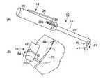
図1(A)に示すように、この実施の形態に係る外科用処置具である持針器10は、術者が操作する操作部(本体部)12と、この操作部12に接続され、患者の体腔内に挿入される挿入部14と、挿入部14の先端部に配設され、各種部位の吻合等に使用する吻合針(被把持物)18(図1(B)参照)を把持する持針部(把持部)16とを備えている。 As shown in FIG. 1A, a
操作部12は、術者に保持される略円筒状のグリップ22と、このグリップ22にそれぞれ配置された持針部回転ダイヤル(円盤体)24および開閉レバー26とを備えている。持針部回転ダイヤル24および開閉レバー26は、術者にグリップ22が保持された状態でそれぞれ操作可能な位置に配設されている。持針部回転ダイヤル24はグリップ22の側面に形成された切り欠き22aから一部が外部に突出されている。持針部回転ダイヤル24は、グリップ22の長手方向軸(中心軸)に対して直交する方向に軸(図示せず)を備えている。このため、持針部回転ダイヤル24は、図1(A)中の矢印α1方向に回転可能である。 The
図2に示すように、グリップ22の側部には、凹部22bが形成されている。グリップ22の凹部22bの基端部には、開閉レバー26の一端部が回転軸26aによって枢着されている。この回転軸26aは、グリップ22の長手方向に対して直交する方向に配設されている。このため、開閉レバー26は、図2中の矢印β1方向に回動可能である。 As shown in FIG. 2, a
開閉レバー26の他端部の回動先端部は、回転軸26aを中心としてグリップ22に対して回動可能である。開閉レバー26の回動先端部(他端部)には、グリップ22の長手方向に対して直交する方向(凹部22b側)にプッシュピン26bが一体的に取り付けられている。このプッシュピン26bの開閉レバー26から突き出した先端部は、略球状に形成されて後述する斜面ブロック34aの斜面34bに接触されている。 The rotation tip of the other end of the opening /
グリップ22には、開閉レバー26の回動可能範囲を制限するストッパ22cが取り付けられている。このため、図2中の矢印β1方向に開閉レバー26を操作したときに、ストッパ22cに開閉レバー26の回動先端部が当接されて開閉レバー26の回動が規制される。 The
グリップ22の先端部と挿入部14の基端部とは、一体的に連結されている。挿入部14には、挿入部14の長手方向軸に沿って後述するスライドロッド34をガイドする第1のガイド部(第1のチャンネル)32aが形成されている。この第1のガイド部32aの基端部は、グリップ22の先端部まで達するとともに、グリップ22の凹部22bにより形成される空間に連通されている。 The distal end portion of the
この第1のガイド部32aには、スライドロッド(スライダ)34が挿入部14の長手方向軸に沿って摺動自在に配設されている。このスライドロッド34の一端(操作部12側端部)は、グリップ22の凹部22bに達している。このスライドロッド34の一端には、斜面34bを有する斜面ブロック34aが一体的に取り付けられている。なお、図3(A)に示すように、スライドロッド34の他端には、後述するプッシュロッド48の丸頭部48aに当接されたテーパ面34cが形成されている。 A slide rod (slider) 34 is slidably disposed along the longitudinal axis of the
挿入部14には、上述した第1のガイド部32aに並設され、後述するベルト38が配設された第2のガイド部(第2のチャンネル)32bが形成されている。この第2のガイド部32bの基端部は、操作部12の上記回転ダイヤル24まで達している。 The
第2のガイド部32bの先端部には、挿入部14の長手方向軸に対して直交し、かつ、上記回転ダイヤル24の軸(図示せず)に平行な軸36aを有する歯車(回転体)36が枢支されている。この第2のガイド部32bには、ベルト(操作力伝達部材)38が挿入部14の長手方向に配設されている。このベルト38は、回転ダイヤル24と歯車36(図3参照)とに適当な張力をもって巻回されている。このため、術者が回転ダイヤル24を回転させると、ベルト38が追従して回転して歯車36を回転させる。 A gear (rotary body) having a
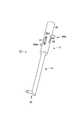
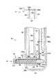
図3(A)に示すように、挿入部14の先端部には、第2のガイド部32bの先端部で第2のガイド部32bに連通し、内周面が球面状のソケット部52が形成されている。図3(A)および図3(B)に示すように、このソケット部52は、挿入部14の先端部の側部に形成された長穴64により挿入部14外に連通されている。この長穴64は、持針部16の後述する持針部本体42の直径よりも僅かに大きな幅を備え、持針部本体42を所定の範囲内で後述する球状体54の中心を支点として傾斜可能な長さを備えている。また、長穴64の、挿入部14の先端部側の縁部と、挿入部14の基端部側の縁部とは、ともに持針部本体42の傾斜角度と同じ角度に傾斜されている。すなわち、挿入部14の内側から外側に向かって広げられている。この長穴64により持針部16は長穴64の長手方向に沿ってのみ移動して挿入部14に対して傾斜する。 As shown in FIG. 3A, the distal end portion of the
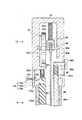
図3(A)に示すように、持針部16は、持針部本体(把持部本体)42と持針ロッド(把持用ロッド)44とコイルバネ(弾性部材)46とプッシュロッド48とを備えている。なお、持針部本体42と持針ロッド44とコイルバネ46とプッシュロッド48とは、持針部本体42の後述する回転中心O1に近接する側、すなわち挿入部14の内部側を一端部とし、回転中心O1から離隔する側、すなわち、挿入部14の内部に対して離隔する側を他端部とする。 As shown in FIG. 3A, the
持針部本体42の一端部(図3(A)中の上端部)には、中空で一部が球状の球状体(把持部球状体)54が形成されている。この球状体54は、挿入部14の上記ソケット部52に嵌め込まれている。このため、挿入部14のソケット部52と、持針部本体42の球状体54とによりボールジョイントが形成されている。ソケット部52の中心は、持針部本体42の回動中心に一致する。なお、ソケット部52と球状体54との間の摩擦力は、持針部本体42の傾斜角度が変化しない、すなわち吻合時に上述した吻合針18の向きが変わらない大きさに設定されている。 A hollow spherical body (gripping part spherical body) 54 that is hollow and partially spherical is formed at one end (the upper end in FIG. 3A) of the needle holder
球状体54の外周面には、上記歯車36の歯部36bに噛み合わせられた歯部54aが形成されている。このため、歯車36が回転すると、球状体54もソケット部52に対して回転する。すなわち、歯車36が回転すると持針部本体42がその中心軸回りに回転する。 On the outer peripheral surface of the
持針部本体42の他端部(図3(A)中の下端部)には、持針部本体42の径方向内方に突出したフランジ部56が形成されている。この持針部本体42には、持針ロッド44が摺動可能に配設されている。この持針ロッド44は、頭部(把持用ロッド頭部)44aとロッド部44bと保持部(挟持部)44cとを備えている。 At the other end (the lower end in FIG. 3A) of the needle holder
頭部44aは持針部本体42の内周面に沿って摺動可能であり、一部が球状体54の内部に配設されている。ロッド部44bは、頭部44aの他端部(図3(A)中の下端部)に一端部(図3(A)中の上端部)が接続され、持針部本体42の中心軸上で持針部本体42の下端部に向かって延びている。保持部44cは、ロッド部44bの一端部(図3(A)中の下端部)に配設され、持針部本体42の下端部のフランジ部56の他端面(図3(A)中の下端面)に対して接離可能である。 The
持針ロッド44の頭部44aの他端面(図3(A)中の下端面)と、持針部本体42のフランジ部56の一端面(図3(A)中の上端面)との間には、コイルバネ46が配設されている。このコイルバネ46の弾性力により、頭部44aは持針部本体42の上方に向かって付勢されている。このため、上述した吻合針18(図1(B)参照)は、持針部本体42のフランジ部56の下端面と持針ロッド44の保持部44cの一端面(図3(A)中の上端面)との間に挟持される。なお、持針ロッド44の頭部44aの一端部(図3(A)中の上端部)は、球面形状に形成されている。頭部44aの上端位置は、保持部44cと持針部本体42との間に吻合針18を把持していない状態で、持針部本体42の回転中心O1と略一致する。 Between the other end surface (the lower end surface in FIG. 3A) of the
挿入部14のソケット部52には、挿入部14の長手方向に直交する方向(図3(A)中の上下方向)に中心軸を有する円柱状の開口62が形成されている。この開口62には、プッシュロッド48が配設されている。プッシュロッド48は、丸頭部(プッシュロッド頭部)48aと軸部48bとを備えている。丸頭部48aは、第1のガイド部32aの先端部の摺動用空間内に配設され、上述したスライドロッド34のテーパ面34cに接触されている。 A
ここで、スライドロッド34は、操作部12の開閉レバー26を押し込む操作(図2中の矢印β1方向の操作)により、挿入部14の先端部側(矢印β2方向)に移動する。このため、スライドロッド34のテーパ面34cにより丸頭部48aが押される。すなわち、スライドロッド34の矢印β2方向の移動が、プッシュロッド48の軸部48bの矢印β3方向の移動に変換される。すなわち、スライドロッド34およびプッシュロッド48は動作方向変換手段を備えている。 Here, the
そうすると、開閉レバー26を押し込む操作によりスライドロッド34は矢印β2の方向にスライドされる。このため、プッシュロッド48は、スライドロッド34が摺動することにより、挿入部14の軸方向に対して直交する方向(矢印β3方向)に摺動自在である。 Then, the
プッシュロッド48の軸部48bの一端部(図3(A)中の下端部)には、球面形状の球面部(円弧形状の円弧状部)48cが形成されている。軸部48bの下端部は、上述した回転中心O1で持針ロッド44の頭部44aの上端部に接触されている。この軸部48bの下端部の球面部48cの中心O2と下端面(中心O1)との間の長さ(半径)は、上述した吻合針18の基端部の太さと略一致するように構成されている。このため、吻合針18が保持部44cと持針部本体42との間に把持された状態では、プッシュロッド48の軸部48bの下端部の球面部48cの中心O2が、持針部本体42の回動中心と一致する。 A spherical surface portion (arc-shaped arc-shaped portion) 48c is formed at one end portion (the lower end portion in FIG. 3A) of the
次に、このような構成を有する持針器10の作用について説明する。 Next, the operation of the
開閉レバー26を図2中の矢印β1方向に操作範囲いっぱいまで操作すると、プッシュピン26bの先端部が斜面ブロック34aの斜面34bに接触して斜面ブロック34aが挿入部14の長手方向に沿って先端部側に移動する。このため、スライドロッド34が第1のガイド部32aに沿って挿入部14の先端部側(矢印β2方向)に摺動する。 When the open /
スライドロッド34が矢印β2方向に移動すると、スライドロッド34のテーパ面34cによってプッシュロッド48の丸頭部48aが図3(A)中の矢印β3方向(下方)に押圧される。このとき、プッシュロッド48の軸部48bの下端部の球面部48cの中心O2は、ソケット部52の中心O1を越えるまで移動する。このため、持針ロッド44の頭部44aの上端部がプッシュロッド48の軸部48bの下端部に押圧される。頭部44aが持針部本体42の内部に沿って移動し、コイルバネ46の付勢力に抗して持針ロッド44の保持部44cを図3(A)中の破線位置まで矢印β4方向に下方に移動させる。 When the
この破線位置に保持部44cが配置された状態では、吻合や縫合に使用するように糸18aが配設された吻合針18を持針部本体42の下端面との間で挟持するのに十分な開き量、すなわち、吻合針18の太さよりも大きな開き量を有する。この状態で吻合針18を保持部44cと持針部本体42の下端部との間に配置し、開閉レバー26から手を放す。コイルバネ46の弾性力により持針ロッド44が移動して吻合針18を保持部44cと持針部本体42の下端面との間に挟み込むと同時に、コイルバネ46の弾性力によりプッシュロッド48とスライドロッド34とが押し戻される。このため、吻合針18は、保持部44cと持針部本体42の下端面との間に挟持(装着)される。 In the state where the holding
次に、吻合針18を保持部44cと持針部本体42の下端面との間に挟持した持針器10の挿入部14を、患者の体に複数開けたポート(図示せず)の1つから体腔内に挿入する。吻合部位70(図1(B)参照)の近辺に持針部16および吻合針18を近づけるとともに、持針部16が吻合に最適な傾斜となるように、一般に内視鏡下外科手術で使用される別のポートから挿入した把持鉗子(図示せず)を使って持針部16の傾斜角度を変更する。このとき、プッシュロッド48の球面部48cの先端中心O2はソケット部52の中心O1に略一致された状態にあるので持針ロッド44が矢印β4方向に動かされることはない。このため、保持部44cと持針部本体42との間に把持(挟持)した吻合針18が脱落することもない。 Next, one of the ports (not shown) in which a plurality of
この状態で持針部回転ダイヤル24を図1(A)中の矢印α1方向に回転操作すると、ベルト38が矢印α2方向に移動し、歯車36を矢印α3方向に回転させる。この歯車36の回転により、持針部本体42が矢印α4方向に回転する。このように持針部16を矢印α4方向に回転させて吻合針18を運針して吻合を実施する。ここで、持針部本体42の球状体54と挿入部14のソケット部52との間の摩擦力は最適に設定されているので、吻合中に持針部本体42の傾斜角度が変わることが防止される。すなわち、吻合針18の向きが吻合中に変わることが防止される。 In this state, when the needle
以上説明したように、この実施の形態によれば、以下の効果が得られる。 As described above, according to this embodiment, the following effects can be obtained.
持針部16を挿入部14の先端部に対して傾斜(回動)させることができ、傾斜状態で保持させたい場合、他の部分を操作する必要がなく、持針部16に他の鉗子等を用いて外力を加えるだけで所望の角度に可変可能である。所望の角度に可変した状態を保持した状態で持針部16を回転させる操作や、持針器10自体を動かす操作などにより、吻合針18を運針して吻合処置を行なうことができるので処置操作を容易に行なうことができる。また、持針器10の構成が簡単で低コストに製造でき、重量も術者に負担がかかるほど大きくなることを防止することができる。 When the
なお、この実施の形態では歯車36の歯部36bと噛み合う球状体54の外周には、通常用いられるインボリュート形状の歯部54aが形成されていることが好適であるが、例えばピッチが同一であるローレットなど、歯車36の歯部36bと噛み合う形状であれば同様の効果が得られる。 In this embodiment, it is preferable that a normally used involute-shaped
次に、第2の実施の形態について図4および図5を用いて説明する。この実施の形態は、第1の実施の形態の変形例であって、第1の実施の形態で説明した部材と同一の部材には同一の符号を付し、詳しい説明を省略する。 Next, a second embodiment will be described with reference to FIGS. This embodiment is a modification of the first embodiment. The same members as those described in the first embodiment are denoted by the same reference numerals, and detailed description thereof is omitted.
図4に示すように、挿入部14の第2のガイド部32bの先端部には、図3(A)に示す歯車36の代わりに摩擦車(回転体)74が枢支されている。持針部本体42の球状体54の外周面からは歯部54aが除去され、球状体54の外周面が摩擦車74の外周面に圧接されている。すなわち、摩擦車74は球状体54に対するブレーキ作用を有する。ここで、持針部本体42の球状体54と挿入部14のソケット部52との互いの接触面の摩擦力は第1の実施の形態で説明した状態よりも小さく、持針部16の傾斜量を調節するのに最適な摩擦力に設定されている。 As shown in FIG. 4, a friction wheel (rotating body) 74 is pivotally supported at the distal end portion of the
第2のガイド部32bの先端部の側部には、1対の溝部76a,76bが形成されている。これら溝部76a,76bの基端部と摩擦車74の回転軸74aとの間には、それぞれ圧縮バネ78a,78bが配設されている。このため、摩擦車74の回転軸74aは、溝部76a,76bにより回転可能、かつ、矢印α2方向に移動可能に挿入部14の先端部側に付勢されている。これら圧縮バネ78a,78bの付勢力は、ベルト38の張力よりも小さく設定されている。このため、圧縮バネ78a,78bを縮ませることができる。球状体54の外周面と摩擦車74との間の摩擦力は、摩擦車74を回転させたときの吻合針18の運針時に持針部16を適切な操作力で回転させることが可能な大きさに設定されている。 A pair of
図5中に破線で示すように、グリップ22には、持針部回転ダイヤル24の回転軸24aを矢印α5方向に摺動可能に配設する1対の溝部82が形成されている。 As shown by a broken line in FIG. 5, the
図4に示すベルト38は、図5に示す持針部回転ダイヤル24の回転を摩擦車74に伝達可能に持針部回転ダイヤル24と摩擦車74とを連結している。ここで、ベルト38はある程度の伸縮性を有しており、摩擦車74が球状体54の外周に圧縮バネ78a,78bにより押し付けられている。この状態で、ベルト38には常に回転力を伝達可能な張力が与えられている。 The
次に、このような構成を有する持針器10の作用について説明する。 Next, the operation of the
術者が挿入部14に対して持針部16を傾斜させたい場合は、図5に示す持針部回転ダイヤル24を矢印α5方向に移動させる。回転ダイヤル24に巻回されたベルト38の張力により、圧縮バネ78a,78bの付勢力に抗して摩擦車74の回転軸74aが溝部76a,76bに沿って挿入部14の基端部側(矢印α2方向)に移動する。このため、摩擦車74が持針部本体42の球状体54の外周面から離れる。この状態で持針部16に外力を加えて球状体54の中心を支点として所望の量だけ長穴64aに沿って傾斜させ、所望の傾斜量となったところで持針部回転ダイヤル24から手を放す。すると、圧縮バネ78a,78bの弾性力により摩擦車74が溝部76a,76bに沿って挿入部14の先端部側に移動して球状体54の外周に押し付けられる。このため、摩擦車74と球状体54との間の摩擦(ブレーキ作用)により、持針部16の傾斜状態が所望の状態に維持される。この状態で第1の実施の形態で説明したように、吻合針18を把持して吻合処置にとりかかる。 When the surgeon wants to tilt the
以上説明したように、この実施の形態によれば、第1の実施の形態で説明した効果に加えて以下の効果が得られる。 As described above, according to this embodiment, the following effects can be obtained in addition to the effects described in the first embodiment.
持針部16の傾斜角度を適切な角度に調節する際、最適な力量で調節が可能であるとともに、吻合操作時には傾斜角度を強固に維持することができる。 When adjusting the inclination angle of the
次に、第3の実施の形態について図6を用いて説明する。この実施の形態は、第1の実施の形態の変形例であって、第1の実施の形態で説明した部材と同一の部材には同一の符号を付し、詳しい説明を省略する。 Next, a third embodiment will be described with reference to FIG. This embodiment is a modification of the first embodiment. The same members as those described in the first embodiment are denoted by the same reference numerals, and detailed description thereof is omitted.
図6に示すように、球状体54の歯部54aの歯幅中心付近に歯車36の歯部36bが噛み合わせられた状態で、持針部本体42は挿入部14の長手方向に対して直交する方向から傾けられている。図6に示す場合、持針部本体42は、挿入部14の先端側に傾けられている。挿入部14の先端部の側部に形成された長穴64aは、球状体54の歯部54aの歯幅中心付近に歯車36の歯部36bが噛み合わせられた状態で持針部本体42が中央に配置されるように形成されている。このため、挿入部14の先端部からさらに先端部側に延びた挿入部14の長手方向軸に対する持針部本体42の傾斜角度θは、90°よりも小さく設定されている。このときの角度は、吻合に適した傾斜角度に適宜に設定可能である。他の構成は第1の実施の形態で説明した構成と同じである。
なお、この実施の形態では、挿入部14の長手方向に対する傾斜角度θが90°よりも小さくなるように構成したが、傾斜角度θが90°よりも大きくなるような構成でも同一の作用が得られる。As shown in FIG. 6, the
In this embodiment, the inclination angle θ with respect to the longitudinal direction of the
次に、このような構成を有する持針器10の作用について説明する。 Next, the operation of the
第1の実施の形態で説明した作用と同様に持針部本体42を長穴64aに沿って傾斜させる。持針部本体42が挿入部14の長穴64aの中央に配置された状態から、図6中で角度θが小さくなる(持針部本体42の中心軸が挿入部42の長手方向軸に近づく)ようにさらに傾斜させる。持針部本体42が長穴64aの中央に配置された状態で、歯車36は球状体54の外周に形成された歯部54aの歯幅の中心に位置するように形成されているため、吻合に適した傾斜角度を基準として十分な可動範囲が得られる。 Similar to the operation described in the first embodiment, the needle holder
以上説明したように、この実施の形態によれば、第1の実施の形態で説明した効果に加えて以下の効果が得られる。 As described above, according to this embodiment, the following effects can be obtained in addition to the effects described in the first embodiment.
持針部本体42の傾斜可動範囲は第1の実施の形態で説明した範囲と同一としても、挿入部14に対する持針部本体42の傾斜角度θを小さく(または大きく)設定することができる。 Even if the tilt movable range of the
なお、ここでは持針部本体42を傾斜させるための入力手段として持針部本体42に直接外力を加えて操作して傾斜させているが、操作部12から挿入部14内部にワイヤやロッド(図示せず)を通して長穴64aの長手方向にワイヤやロッドを押し引きすることが可能な構成を設け、このワイヤやロッドを操作部12で操作することにより持針部16を傾斜させることもできる。 Here, as an input means for tilting the needle holder
次に、第4の実施の形態について図7ないし図12を用いて説明する。 Next, a fourth embodiment will be described with reference to FIGS.
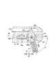
図7に示すように、この実施の形態に係る持針器(外科用処置具)10は、操作部12と挿入部14と持針部(処置部)16とを備えている。持針器10には、持針部16を回転させる回転機構と、持針部16の角度変化を許容する状態と規制する状態とを切り替える角度可変切替機構と、持針部16で針を挟持可能に保持部44cを持針部本体42に対して開閉させる把持部開閉機構とを備えている。 As shown in FIG. 7, the needle holder (surgical treatment instrument) 10 according to this embodiment includes an
図8および図9に示すように、上述した回転機構、角度可変切替機構および把持部開閉機構は、操作部12のグリップ22、およびシース80を備えた挿入部14に内挿されている。図8に示すように、このシース80の基端部は、グリップ22の先端部に一体的に連結されている。 As shown in FIGS. 8 and 9, the rotation mechanism, the variable angle switching mechanism, and the gripper opening / closing mechanism described above are inserted in the
まず、回転機構について説明する。図8に示すように、グリップ22には、回転ダイヤル24の後述する回転軸84bを受ける1対の軸受溝82a,82bが形成されている。これら軸受溝82a,82bは、グリップ22の内側でグリップ22の長手方向に沿って所定の長さに形成されている。 First, the rotation mechanism will be described. As shown in FIG. 8, the
回転ダイヤル24は、円盤体84aと、この円盤体84aの中心を貫通し、固着された回転軸84bとを備えている。円盤体84aの側部には、断面が略U字状の操作部プーリ牽引部材86と、この操作部プーリ牽引部材86の内側に配置された操作部プーリ88とが配置されている。これら円盤体84a、操作部プーリ牽引部材86および操作部プーリ88には、回転軸84bが貫通されている。操作部プーリ88は、回転軸84bに対して固着されている。操作部プーリ牽引部材86は、回転軸84bに対して回転自在である。回転軸84bの両端部は、それぞれ軸受溝82a,82bに支持されている。なお、回転ダイヤル24の円盤体84aの一部は、術者が回動操作可能なように、グリップ22に設けられた両サイドの切り欠き22a(図7参照)よりグリップ22から突出している。このため、円盤体84aを回転させると、回転軸84bとともに操作部プーリ88が回転する。操作部プーリ牽引部材86は、回転軸84bが回転してもその位置に留まる。 The
操作部プーリ牽引部材86は、グリップ22の基端部(持針部(把持ユニット)16に対して遠位側端部)の内面(図8中の上端面)に対してコイルバネ90aによって接続されている。このコイルバネ90aは、操作部プーリ牽引部材86をグリップ22の基端部側(図8中の上側)に向かって付勢している。このため、円盤体84a、回転軸84b、操作部プーリ牽引部材86および操作部プーリ88は、グリップ22の基端部側(図8中の上側)に向かって付勢されている。 The operation portion
操作部プーリ88には、ワイヤ(操作力伝達部材)92が巻回されている。このワイヤ92は、挿入部14の先端部側に延びている。このため、円盤体84aが回転されると、ワイヤ92が挿入部14の長手方向に沿って進退する。 A wire (operation force transmission member) 92 is wound around the
図9に示すように、持針部16は、円筒状の持針部本体42と持針ロッド44とコイルバネ46とを備えている。この円筒状の持針部本体42の一端部(図9中の右端部)および他端部(図9中の左端部)は共に開口され、他端部には径方向内方に突出したフランジ部56が形成されている。 As shown in FIG. 9, the
この持針部本体42の内部には、持針ロッド44が挿通されている。この持針ロッド44は、頭部44aとロッド部(スライド軸)44bと保持部(挟持部)44cとを備えている。 A
頭部44aは、持針部本体42の一端部(図9中の右端部)で持針部本体42の内周面に沿って摺動可能である。 The
ロッド部44bは、頭部44aの他端部(図9中の左端部)に一端部(図9中の右端部)が接続され、持針部本体42の中心軸上で持針部本体42の他端部(保持部44c)に向かって延びている。保持部44cは、ロッド部44bの他端部(図9中の左端部)に配設され、持針部本体42の他端部のフランジ部56の図9中の左側端面(以下、保持部側端面という)56aに対して接離可能である。 The
保持部44cはリング状に形成され、ロッド部44bの他端部(図9中の左端部)に対して例えばレーザ溶接により結合されている。この保持部44cは、持針部本体42の他端部の外側に配設され、フランジ部56の保持部側端面56aに対して接離可能である。 The holding
持針ロッド44の頭部44aの他端部と、持針部本体42のフランジ部56の図9中の右側端面(以下、弾性部材側端面という)56bとの間には、コイルバネ46が配設されている。このコイルバネ46は、フランジ部56bの弾性部材側端面56bと持針ロッド44の頭部44aの一端部との間で圧縮されながら装填されている。このため、そのコイルバネ46の装備力量により、頭部44aは持針部本体42の一端部側に向かって付勢されている。よって、保持部44cが常にフランジ部56の保持部側端面56aに対して所定の力量で付勢されている。このため、例えば上記吻合針18(図1(B)参照)がフランジ部56の保持部側端面56aと保持部44cとの間に挟持されていないときには、保持部44cはフランジ部56の保持部側端面56aに対して所定の力量で当接された状態で付勢されている。一方、上記吻合針18(図1(B)参照)は、持針部本体42のフランジ部56の保持部側端面56aと持針ロッド44の保持部44cとの間に挟持される。 A
筒状の持針部本体42の他端部の外周面には、持針部本体42の中心軸と同一軸上に中心軸を有するプーリ(回転体)94が装着(固着)されている。このプーリ94には、上記ワイヤ92が巻回されている。このため、このプーリ94と操作部プーリ88(図8参照)とは、ワイヤ92によって連結されている。このとき、図8に示す操作部プーリ牽引部材86とグリップ22の基端部との間に配設されたコイルバネ90aによって、ワイヤ92は操作部プーリ牽引部材86、回転軸84bおよび操作部プーリ88を介してグリップの基端部側(図8および図9中の上側)に向かって引っ張られている。 A pulley (rotary body) 94 having a central axis on the same axis as the central axis of the
次に、把持部開閉機構について説明する。図8に示すように、グリップ22の軸受溝82a,82bよりも先端部側で、グリップ22の側部には、グリップ22の長手方向に沿って長穴96が形成されている。この長穴96は、グリップ22の内部および外部を連通している。この長穴96には、L字状に屈曲されたL字部材98aが配設され、基端部がグリップ22の外部に突出され、先端部が挿入部14の先端部側に延びている。このL字部材98aの基端部には、開閉ノブ98bが取り付けられている。グリップ22の長穴96の先端部には、グリップ22の内方に突出した第1の突出部100aが形成されている。L字部材98aの屈曲部と第1の突出部100aとの間には、L字部材98aの外周にコイルバネ90bが配設されている。この第1の突出部100aには、L字部材98aが貫通された貫通孔がグリップ22の長手方向に沿って形成されている。この貫通孔によりL字部材98aは挿入部14の長手方向に沿って直線上に摺動可能に保持される。 Next, the gripper opening / closing mechanism will be described. As shown in FIG. 8, a
図9に示すように、L字部材98aの先端部にはテーパ面を有するクサビ部98cが形成されている。持針ロッド44の頭部44aの球状部の頂点に対して、クサビ部98cが操作部12側から配置されている。クサビ部98cに設けられたテーパ面の先端と、持針ロッド44の頭部44aの球状部の頂点とは、略同一線上に並ぶように配置されている。このため、術者が図8に示す開閉ノブ98bをコイルバネ90bの付勢力に抗して長穴96に沿ってグリップ22の先端部側に移動させてL字部材98aを挿入部14の先端部側(図9中の下方)に移動させると、クサビ部98cを持針ロッド44の頭部44aに当接可能である。 As shown in FIG. 9, the
次に、角度可変切替機構について説明する。図8に示すように、グリップ22の先端部の側部で、上記長穴96に略対向する位置には、グリップ22の長手方向に直交する方向に貫通孔102が形成されている。この貫通孔102には、角度可変切替ボタン(ブレーキ操作部)104が配設されている。この角度可変切替ボタン104は、貫通孔102に沿って摺動可能な軸部104aと、軸部104aの一端部に装着されてグリップ22の外部に配設されたボタン部104bと、軸部104aの他端部に連結されてグリップ22の内部に配設されたクサビ部材104cとを備えている。ボタン部104bとグリップ22の外周面との間には、軸部104aの外周にコイルバネ90cが配設されている。このため、ボタン部104bは、クサビ部材104cが後述するブレーキ部材106の傾斜面を有する穴部106aに対して常に離れるように付勢されている。 Next, the variable angle switching mechanism will be described. As shown in FIG. 8, a through
グリップ22の先端部で、上述した貫通孔102よりもグリップ22の基端部側(図8中の上側)には、グリップ22の内方に突出した第2の突出部100bが形成されている。この第2の突出部100bの挿入部14の先端部側の面には、コイルバネ90dの一端部(図8中の上端部)が支持されている。このコイルバネ90dの他端部(図8中の下端部)には、挿入部14の長手方向に沿って先端部側に延びたブレーキ部材106の基端部が装着されている。コイルバネ90dは、ブレーキ部材106を挿入部14の先端部側(図8中の下側)に付勢している。このブレーキ部材106の基端部には、上述したクサビ部材104cを挿脱可能な穴部106aが形成されている。この穴部106aは、クサビ部材104cの斜面部に当接される斜面部を備えている。 A second projecting
図9に示すように、持針部本体42の外周面には、円筒部材(円柱部材)110が配設されている。この円筒部材110は、その中心軸に対して直交する方向に持針部本体42が配設される貫通孔が形成されている。持針部本体42は、円筒部材110の貫通孔に対して回転可能である。 As shown in FIG. 9, a cylindrical member (column member) 110 is disposed on the outer peripheral surface of the needle holder
図10に示すように、円筒部材110の中心軸上には、1対の枢軸110aが配設されている。これら枢軸110aは、挿入部14のシース80に設けられた穴(図示せず)に挿入されている。これら枢軸110aは、挿入部14の長手方向に対して直交するとともに持針部本体42の軸方向に対して直交する方向に配設されている。 As shown in FIG. 10, a pair of
図9に示すように、挿入部14のシース80の先端部には、挿入部14の先端から基端部側に延びた突出部114が形成されている。この突出部114の挿入部14の基端部側の面(図9中の上端部)には、円筒部材110の外周面の一部を支持するように、円筒部材110の外周面と同じ形状を有する円筒接触面114aが形成されている。 As shown in FIG. 9, a protruding
上述したブレーキ部材106は、この円筒接触面114aに対向した状態でブレーキ面(当接面)106bが形成されている。このブレーキ面106bは切削加工や放電加工等により表面を荒らしていることが望ましい。また、ダイヤモンド、サファイヤなどの超硬素材の粒子を金属メッキで付着させて荒らしてあっても良い。なお、ブレーキ部材106の中心軸は、円筒部材110の中心軸(枢軸110a)に直交し、円筒接触面114aを支持する突出部114の中心軸上に位置されている。 The
次に、このような構成を有する持針器10の作用について説明する。 Next, the operation of the
術者は図8に示す開閉ノブ98bをグリップ22の長穴96に沿って挿入部14の先端部側にスライドさせる。L字部材98aの先端部のクサビ部98cが挿入部14の先端部側に移動する。図11に示すように、クサビ部98cの斜面部が持針ロッド44の頭部44aの球状部に当接されて頭部44aを持針ロッド44の他端部側(図11中の左方向)にスライドさせるように挿入部14の先端部側(図11中の下方向)に移動させる。すなわち、持針ロッド44の軸部(スライド軸)44aを挿入部14の持針部本体42の軸方向に沿ってスライドさせる。このとき、コイルバネ46が持針ロッド44の頭部44aと持針部本体42のフランジ部56の弾性部材側端面56bとの間で圧縮させられる。このため、コイルバネ46の付勢力に抗して保持部44cが持針部本体42のフランジ部56の保持部側端面56aから離れて保持部44cと持針部本体42のフランジ部56との間に吻合針18を把持するための隙間が生ずる。このとき、保持部44cと持針部本体42のフランジ部56との間に吻合針18を配置する。 The operator slides the opening /
術者が開閉ノブ98bから指を離すと、グリップ22内のコイルバネ90bの付勢力に従ってL字部材98aが挿入部14の基端部側に移動させられる。すなわち、クサビ部98cが元の位置に移動させられて持針ロッド44の頭部44aから離れる。このため、コイルバネ46の付勢力(バネ力)により頭部44aおよび軸部(スライド軸)44bは元の位置に自動的に復帰しようとし、保持部(リング部材)44cは持針部本体42のフランジ部56の保持部側端面56aに当接する方向に移動する。 When the operator releases his / her finger from the opening /
コイルバネ46は持針部本体42のフランジ部56と持針ロッド44の頭部44aとの間で持針ロッド44の長手方向で他端部側(図9中の右側)に付勢されているため、持針部本体42のフランジ部56と保持部44cとの間には常に圧縮力が生じている。よって、吻合針18(図1(B)参照)などを保持部44cとフランジ部56との間で十分な把持力で把持することができる。 The
術者が回転ダイヤル24を矢印α1方向に回転させると、図10に示すように、円盤体84aを介して回転軸84bが回転する。このため、操作部プーリ88が回転し、ワイヤ92が操作部プーリ88の回転に伴って矢印α2方向に移動する。このワイヤ92の移動によりプーリ94が矢印α3方向に回転し、持針部本体42が矢印α4方向に回転する。すなわち、回転ダイヤル24の回転により、円盤体84a、回転軸84b、操作部プーリ88、ワイヤ92を介してプーリ94に回転力が伝達されて持針部16が回転する。このとき、円筒部材110に対して持針部本体42が持針部本体42の中心軸回りに回転する。結果として、吻合針18を把持した状態で持針部本体42の軸周りに吻合針18を自在に回転させることができる。 When the surgeon rotates the
ブレーキ部材106は、ブレーキ部材106の基端部のコイルバネ90dによって、ブレーキ面106bが円筒部材110の外周面に付勢されて当接されている。すなわち、ブレーキ部材106のブレーキ面106bは、円筒部材110の外周面に圧接されている。このため、ブレーキ面106bと円筒接触面114aとの間で円筒部材110を枢軸110a回りに動かさないように保持している。 The
術者が角度可変切替ボタン部104bをグリップ22の内側に押すと、クサビ部材104cの傾斜面が、ブレーキ部材106の穴部106aの傾斜面に当接し、かつ、傾斜面をスライドして穴部106aをグリップ22の基端部側に移動させる。ブレーキ部材106の穴部106aがグリップ22の基端部側に移動すると、図12に示すように、ブレーキ部材106のブレーキ面106bが円筒部材110から離れてブレーキが解除される。このため、円筒部材110が枢軸110aの軸周りに回動自在な状態となる。 When the surgeon pushes the variable angle
この状態で術者が図12に示すように、体腔内において術者がもう一方の手で把持した把持鉗子200などで持針部本体42を押すと、持針部本体42の挿入部14の長手方向に対する突出角度が挿入部14の先端部の側部に形成された長穴64bの範囲内で変更される。持針部本体42が挿入部14の長手方向に対して所望の角度となったときに、角度可変切替ボタン部104bの押圧を解除すると、コイルバネ90dの付勢力によりクサビ部材104cがブレーキ部材106の穴部106aから抜かれるとともに、コイルバネ90の付勢力によりブレーキ部材106が挿入部14の先端部側に移動する。このため、ブレーキ部材106のブレーキ面106bが再び円筒部材110に当接されて持針部本体42の角度を保持する。 In this state, as shown in FIG. 12, when the operator presses the
図9に示すように、コイルバネ90aは常に操作部プーリ牽引部材86を介して操作部プーリ88および回転軸84bをグリップ22の基端部側に引っ張る方向に付勢している。このため、常にワイヤ92にはテンションがかけられている。 As shown in FIG. 9, the
図12に示すように、持針部本体42の挿入部14の先端部に対する突出角度を変えるとシース80の長手方向軸に対してワイヤ92が傾けられる。このため、図8に示す回転ダイヤル24の位置を同じ位置に配置すると考えると、ワイヤ92が傾けられる以前のプーリ94と操作部プーリ88との間の長さとでワイヤ92の長さが合わなくなる。操作部プーリ牽引部材86とグリップ22の基端部の当接面との間に固着されたコイルバネ90aが伸び、回転ダイヤル24全体、すなわち、円盤体84aの回転軸84bが軸受溝82a,82bに沿って操作部プーリ88、操作部プーリ牽引部材86が先端側に移動する。このため、ワイヤ92の長さのつじつまを合わせ、ワイヤ92に対して常に所定のテンションをかけた状態を継続することができる。 As shown in FIG. 12, the
角度を変更した状態で角度可変ボタン部104bを押してブレーキ面106bを解除すると、ワイヤ92には常にテンションがかけられているため、ワイヤ92がプーリ94を介して持針部本体42を元の位置に戻そうとする力が働く。持針部本体42は自動的に元の位置に復元される。 When the angle
以上説明したように、この実施の形態によれば、以下の効果が得られる。 As described above, according to this embodiment, the following effects can be obtained.
持針部本体42の角度を手術の状況によって可変させることができるので、別の処置具に持ち替える必要がなく、使い勝手を向上させることができるばかりでなく、手術時間が短縮され、患者に対する侵襲を減少させることができる。 Since the angle of the needle holder
持針部16は外部から力を与えることなく独立して吻合針18の把持状態を維持しているため、従来あったように把持力伝達手段が回動操作の負荷に影響を与えることは全くない。よって、把持部に把持対象を把持した状態でも回動がスムーズであり、使い勝手を向上させることができる。加えて、術者は把持対象を把持するために、持針器10に常に力を与えなくても良いので、極めて操作性が良い。術者は把持対象物(被把持物)の回動やその他の操作に集中することができる。 Since the
次に、第5の実施の形態について図13を用いて説明する。この実施の形態は、第4の実施の形態の変形例であって、第4の実施の形態で説明した部材と同一の部材には同一の符号を付し、詳しい説明を省略する。第4の実施の形態と異なる部分のみ説明する。 Next, a fifth embodiment will be described with reference to FIG. This embodiment is a modification of the fourth embodiment. The same members as those described in the fourth embodiment are denoted by the same reference numerals, and detailed description thereof is omitted. Only parts different from the fourth embodiment will be described.
図13(A)に示すように、図9に示すブレーキ部材106および突出部114は、挿入部14のシース80の内部から除去されている。 As shown in FIG. 13A, the
挿入部14のシース80の先端部には、長穴64cが形成されている。この長穴64cのそれぞれの縁部には、第1および第2の永久磁石120a,120bが配設されている。第1の永久磁石120aは、第2の永久磁石120bに近接する位置にS極が配置されている。第2の永久磁石120bは、第1の永久磁石120aに近接する位置にN極が配置されている。第1の永久磁石120aのS極には、第1の滑り面部材122aが配設されている。第2の永久磁石120bのN極には、第2の滑り面部材122bが配設されている。第1および第2の滑り面部材122a,122bの互いに対向する面には、円筒部材110が摺動回転可能に当接されて支持されている。これら滑り面部材122a,122bと円筒部材110の外周面とが当接されているので、円筒部材110の回転が制限されている。この円筒部材110は、枢軸110a(図10参照)により挿入部14のシース80に保持されている。 An
円筒部材110の内部で、持針部本体(回動部材)42の外周面には、電磁石(ソレノイド)124が装着されている。図13(B)に示すように、電磁石124は、コア126の周囲に導線128が幾重にも巻き付けられて形成されている。コア126は、例えば鉄等、円筒状で透磁率の高い素材で形成されている。 An electromagnet (solenoid) 124 is mounted on the outer peripheral surface of the needle holder main body (rotating member) 42 inside the
図13(A)に示すように、この電磁石124の導線128の線材の両端はそれぞれ電線130a,130bに電気的に接続されている。これら電線130a,130bは挿入部14のシース80を通して操作部12に配置されている。操作部12には電源・スイッチユニット132が設けられている。この電源・スイッチユニット132のスイッチ132aは操作部12に設けられた図示しない押しボタンスイッチにより操作される。なお、図13(A)中に示したスイッチ132aの状態では、電磁石124の符号124aで示す位置(図13(A)中の右側)がS極、符号124bで示す位置(図13(A)中の左側)がN極である。 As shown in FIG. 13A, both ends of the wire of the
次に、このような構成を有する持針器10の作用について説明する。 Next, the operation of the
電磁石124の符号124bで示す位置のN極と第1の永久磁石120aのS極との間、および、電磁石124の符号124aで示す位置のS極と第2の永久磁石120bのN極との間は、それぞれ引き合う引力が働いている。このため、電磁石124の図13(A)中の符号124aで示す位置がS極に磁化された状態では図13(A)に示した状態で持針部本体42の位置が維持される。 Between the N pole at the position indicated by reference numeral 124b of the
電源・スイッチユニット132のスイッチ132aを切り替えると、電磁石124の極性が逆転する。電磁石124の図13(A)中の符号124aで示す位置(紙面右側)がN極に切り替わり、符号124bで示す位置(紙面左側)がS極に切り替わる。このため、電磁石124の符号124bで示すS極と第1の永久磁石120aのS極との間、および、電磁石124の符号124aで示すN極と第2の永久磁石120bのN極との間は、それぞれ反発し合う斥力が働く。第1および第2の永久磁石120a,120bは動かないので、円筒部材110が中心軸(枢軸110a)を支点として滑り面部材122a,122bを摺動しながら回動する。このため、持針部本体42が回動する。このとき、第1の永久磁石120aのS極に電磁石124の符号124aで示すN極が近接し、第2の永久磁石120bのN極に電磁石124の符号124bで示すS極が近接するまで回動する。なお、持針部本体42は、第1の滑り面部材122aに持針部本体42が当接されるまで回動する。すなわち、第1および第2の滑り面部材122a,122bの縁部が、長穴64cの縁部として規定されている。 When the
以上説明したように、この実施の形態によれば、以下の効果が得られる。 As described above, according to this embodiment, the following effects can be obtained.
上述した第4の実施の形態では、持針部16の角度を可変させるのに例えば他の鉗子200(図12参照)など外部からの力が必要であったが、このような外部からの力が不要で、スイッチ132aの操作のみで持針部本体42の角度を可変させることができるので持針器10の使い勝手を向上させることができる。このとき、電源・スイッチユニット132のスイッチ132aを切り替えることによって、持針部16は、図13(A)中に実線で示す位置と、破線で示す位置との二段階に可変させることができる。 In the above-described fourth embodiment, an external force such as another forceps 200 (see FIG. 12) is required to change the angle of the
次に、第6の実施の形態について図14および図15を用いて説明する。この実施の形態は、第4の実施の形態の変形例であって、第4の実施の形態で説明した部材と同一の部材には同一の符号を付し、詳しい説明を省略する。 Next, a sixth embodiment will be described with reference to FIGS. 14 and 15. This embodiment is a modification of the fourth embodiment. The same members as those described in the fourth embodiment are denoted by the same reference numerals, and detailed description thereof is omitted.
持針部本体42の外周面には、スリーブ142が配設されている。すなわち、持針部本体42は、スリーブ142に挿入されている。このスリーブ142の一端部(図14(A)中の右端部)にはL字型のワイヤ牽引部材144の一端が固着されている。ワイヤ牽引部材144の他端には、コア(枢軸)146aを介して第1のワイヤ受けプーリ(ワイヤ受部材)146が回転自在に配設されている。第1のワイヤ受けプーリ146はワイヤ92を引っ掛けるような形態で接するように配置されている。第1のワイヤ受けプーリ146から操作部12側には、ワイヤ92を挟んで第2のワイヤ受けプーリ148が枢軸148aを介して回転自在にシース80に設けられている。第1および第2のワイヤ受けプーリ146,148はワイヤ92を互いによって挟み、かつワイヤ92の直線状態を維持する位置関係にある。 A
スリーブ142には第1および第2のリンク棒150,152がそれぞれ枢軸150a,152aを介して接続されている。これらリンク棒150,152はそれぞれ枢軸150a,152aを中心として互いに対して平行に回動自在である。 First and
シース80の先端部にはシース80の内方に突出した固定台154が設けられている。第1のリンク棒150の枢軸150aの位置の移動を防止するため、その枢軸150aは固定台154に挿入されて固定されている。 A fixed
第1および第2のリンク棒150,152の他端部は、操作部12のグリップ(操作カバー)22(ここでは図示せず)の中で枢軸156a,156bを介してリンク移動棒156に連結されている。第1および第2のリンク棒150,152は枢軸150a,152aを中心としてそれぞれリンク移動棒156に対して回動自在である。なお、図14(B)に示すように、リンク移動棒156の一端部には、上記枢軸156bが配設されている。 The other end portions of the first and
一方、操作部12側の枢軸156aの位置の移動を防止するため、その枢軸156aはグリップ22に設けられた図示しない穴に挿入されて固定されている。 On the other hand, in order to prevent the movement of the position of the
図14(B)に示すように、リンク移動棒156の他端部には、角度可変ノブ(傾斜操作部)158が固着されている。この角度可変ノブ158は術者によって操作可能にグリップ22の外側に突出されている。 As shown in FIG. 14B, a variable angle knob (tilting operation unit) 158 is fixed to the other end of the
次に、このような構成を有する持針器10の作用について説明する。 Next, the operation of the
図15(B)に示すように、術者が角度可変ノブ158を挿入部14の先端部側に移動させると、枢軸156aを中心としてリンク移動棒156が回動する。平行リンクの作用によって枢軸150aを中心としてスリーブ142がリンク移動棒156と平行に回動させられる。このため、図15(A)に示すように、持針部本体42の角度を長穴64bの範囲内など、所定の範囲内で可変可能である。 As shown in FIG. 15B, when the surgeon moves the angle
持針部本体42の角度を変化させたとき、第1および第2のワイヤ受けプーリ146,148によってワイヤ92が引っ張られる。第1のワイヤ受けプーリ146とプーリ94との間ではワイヤ92はプーリ94のフランジ94aと平行になるように位置関係が保たれる。 When the angle of the needle holder
第2のワイヤ受けプーリ148によって第2のワイヤ受けプーリ148から操作部12側に向かったワイヤ92は、シース80の軸方向に平行な状態を保つことが可能である。よって、第4および第5の実施の形態に比べて持針部16の角度を変えたときのプーリ94とワイヤ92の引っ掛かり方が安定する。 The
このとき、操作部プーリ88とプーリ94の間でのワイヤ92のテンション維持機構(第1および第2のワイヤ受けプーリ146,148)が働いているので、第4の実施の形態の図10で示したように、ワイヤ92の軸方向の長さのつじつまが合わなくなってもこれはコイルバネ90aによって吸収される。 At this time, the tension maintaining mechanism (the first and second
以上説明したように、この実施の形態によれば、以下の効果が得られる。 As described above, according to this embodiment, the following effects can be obtained.
第4の実施の形態に比べ、持針部16の角度を操作部での角度可変ノブ158の操作のみで変えることができるので使い勝手を向上させることができる。 Compared with the fourth embodiment, the angle of the
第5の実施の形態に比べ、持針部16の角度を連続的に変化させることができるので、使い勝手を向上させることができる。 Compared to the fifth embodiment, the angle of the
次に、第7の実施の形態について図16を用いて説明する。この実施の形態は、第1の実施の形態の変形例であって、第1の実施の形態で説明した部材と同一の部材には同一の符号を付し、詳しい説明を省略する。 Next, a seventh embodiment will be described with reference to FIG. This embodiment is a modification of the first embodiment. The same members as those described in the first embodiment are denoted by the same reference numerals, and detailed description thereof is omitted.
図16(A)に示すように、持針部本体42aは、球状体(把持部球状体)162と、この球状体162から延びた管部164とを一体的に備えている。管部164は、球状体162の中心から径方向外方に延びている。球状体162および管部164には、管部164の中心軸を通るとともに球状体162の中心を通る貫通孔166が形成されている。この貫通孔166は、球状体162の内部で段差部166aを備え、管部164および球状体162の管部164側が小径部166bで、球状体162では小径部166bよりも大径の大径部166cに形成されている。 As shown in FIG. 16A, the needle holding portion main body 42a is integrally provided with a spherical body (gripping portion spherical body) 162 and a
このような貫通孔166には、持針ロッド44とコイルバネ46とが配設されている。持針ロッド44は、頭部44aとロッド部44bと保持部44cとを備えている。頭部44aは、ロッド部44bに接続された大径部168aと、この大径部168aに形成された小径部168bとを備え、小径部168bの先端(図16(A)中の上端)には、球体状部168cが形成されている。 In such a through
コイルバネ46は、持針ロッド44の頭部44aの大径部168aと貫通孔166の大径部166cの段差部166aとの間に配設されている。このため、持針ロッド44は、保持部44cが管部164の先端部に当接される方向に付勢されている。 The
挿入部14の先端部のソケット部52には、例えば2つなど複数の穴部(凹部)172a,172bが形成されている。これら穴部172a,172bの径は、持針ロッド44の頭部44aの大径部168aの外径よりも僅かに大きく形成されている。これら穴部172a,172bの中央部には、頭部44aの小径部168bの外径よりも僅かに大きい小穴部172c,172dが形成されている。2つの穴部172a,172bの小穴部172c,172dは、溝部174によって連通されている。 A plurality of hole portions (concave portions) 172a and 172b such as two are formed in the
このようにして、ソケット部52に対して球状体162を位置決めする位置決め機構が形成されている。 In this way, a positioning mechanism for positioning the
挿入部14の第1のガイド部32aには、軸方向に摺動可能なスライドロッド34が配設されている。このスライドロッド34の先端部には、持針ロッド44の頭部44aの小径部168bと接する円弧状面34dが形成されている。 A
第2のガイド部32bの先端部には、摩擦車74が配設されている。この摩擦車74は、持針部本体42aの球状体162に対して常に押し当てられている。この摩擦車74は、第2のガイド部32bの先端部で挿入部14の軸方向に直交する方向に回転軸74aを備えている。この回転軸74aには、ベルト38がかけられている。このベルト38は操作部12で回転ダイヤル24(図1(A)参照)にかけられている。 A
次に、このような構成を有する持針器10の作用について説明する。 Next, the operation of the
術者は操作部12からスライドロッド34を挿入部14の先端部側に向けて移動させる。スライドロッド34の円弧状面34dで持針ロッド44の頭部44aの小径部168bを押して球状体162の内部のコイルバネ46を縮ませる。管部164の先端面と保持部44cとの間を開け、吻合針18(図1(B)参照)を管部164の先端面と保持部44cとの間に位置させる。この状態でスライドロッド34を挿入部14の基端部側に移動させる。コイルバネ46の弾性力により吻合針18が管部164の先端面と保持部44cとの間に把持(挟持)される。 The surgeon moves the
操作部12の回転ダイヤル24(図1(A)参照)を回転操作することによりベルト38を動かして摩擦車74を回転させる。摩擦車74と球状体162との間の摩擦により球状体162と管部164と持針ロッド44とが吻合針18とともに貫通孔166の軸周りに回転する。 By rotating the rotary dial 24 (see FIG. 1A) of the
挿入部14に対する管部164や保持部44cの方向を変えたい場合は、保持部44cを管部164の先端面に対して離隔する方向に引っ張り、コイルバネ46を圧縮する。持針ロッド44の頭部44aの大径部168aを穴部172aから抜くとともに小穴部172cから小径部168bを抜き、小径部168bを溝部174に沿って動かして大径部168aを他の穴部172bに入れるとともに小径部168bを小穴部172dに入れる。 When it is desired to change the direction of the
このように持針部16の方向を変えた場合でも吻合針18の把持回転は同様の操作で可能である。 Thus, even when the direction of the
以上説明したように、この実施の形態によれば、以下の効果が得られる。 As described above, according to this embodiment, the following effects can be obtained.
持針部16の方向を簡単に変えることができ、方向が安定した状態に保つことができる。 The direction of the
次に、第8の実施の形態について図17を用いて説明する。この実施の形態は、第7の実施の形態の変形例であって、第7の実施の形態で説明した部材と同一の部材には同一の符号を付し、詳しい説明を省略する。 Next, an eighth embodiment will be described with reference to FIG. This embodiment is a modification of the seventh embodiment. The same members as those described in the seventh embodiment are denoted by the same reference numerals, and detailed description thereof is omitted.
この実施の形態に係る持針器10は、ソケット部52に対して球状体162を位置決めする位置決め機構を備えている。 The
球状体162の外周面には、例えば2つなど複数のV字溝(凹部)178a,178bが形成されている。これらV字溝178a,178bは、上記貫通孔166の軸回りに球状体162の外周面に形成されている。挿入部14のソケット部52の内周面には、凹部52aが形成され、この凹部52aの底部には、圧縮バネ182が配設されている。この凹部52aの内部で圧縮バネ182の上側には、上述したV字溝178a,178bに係合可能なピン180が配設されている。 A plurality of V-shaped grooves (recesses) 178 a and 178 b such as two are formed on the outer peripheral surface of the
挿入部14の先端部には持針ロッド44が回転、移動可能な形状の溝部184が形成されている。他の構成は第7の実施の形態と同様である。 A
次に、このような構成を有する持針器10の作用について説明する。 Next, the operation of the
操作部12の回転ダイヤル24(図1(A)参照)を回転操作することによりベルト38を動かして摩擦車74を回転させる。摩擦車74と球状体162との間の摩擦により球状体162と管部164と持針ロッド44とが吻合針18とともに持針ロッド44の軸周りに回転する。このとき、V字溝178aとピン180とが係合状態を保持しながらV字溝178aに沿って球状体162がピン180の回りを回転する。 By rotating the rotary dial 24 (see FIG. 1A) of the
挿入部14に対して持針部16の方向を変える場合、挿入部14に対して管部164を指等で矢印γ方向に押す。このため、V字溝178aでピン180を押して圧縮バネ182を圧縮してピン180を凹部52aの内部に引っ込める。この状態で持針ロッド44を溝部184に沿って動かし、他のV字溝178bにピン180を係合させる。 When changing the direction of the
このように持針部16の方向を変えた場合でも針18を把持し、管部164を回転させる動作は上述した操作と同様の操作で可能である。 Thus, even when the direction of the
以上説明したように、この実施の形態によれば、第7の実施の形態で得られた効果と同様の効果が得られる。 As described above, according to this embodiment, the same effect as that obtained in the seventh embodiment can be obtained.
これまで、いくつかの実施の形態について図面を参照しながら具体的に説明したが、この発明は、上述した実施の形態に限定されるものではなく、その要旨を逸脱しない範囲で行なわれるすべての実施を含む。 Although several embodiments have been specifically described so far with reference to the drawings, the present invention is not limited to the above-described embodiments, and all the embodiments performed without departing from the scope of the invention are described. Including implementation.
上記説明によれば、下記の事項の発明が得られる。また、各項の組み合わせも可能である。 According to the above description, the following matters can be obtained. Combinations of the terms are also possible.
[付記]
(付記項1) 患者体腔内に挿入され先端に吻合用針を把持して運針するための手術用器具において、挿入部に対して傾斜自在かつ自転可能にボールジョイント部で接続された傾斜部と、傾斜部の先端に配置され弾性部材の弾性力により針を把持する把持部と、前記傾斜部の内部に配置され前記把持部を開くために前記弾性部材を間接的に押圧するための部材で押圧する部分が球形状をしたプッシュロッドとから構成され、把持部に針を把持した状態では前記プッシュロッドの球形状の中心位置とボールジョイントの回転中心位置が略一致していることを特徴とする先端傾斜角可変持針器。[Appendix]
(Additional Item 1) In a surgical instrument that is inserted into a patient's body cavity and is operated by grasping an anastomosis needle at the tip thereof, an inclined part connected to the insertion part by a ball joint part so as to be able to tilt and rotate. A grip portion that is disposed at the tip of the inclined portion and grips the needle by the elastic force of the elastic member, and a member that is disposed inside the inclined portion and indirectly presses the elastic member to open the grip portion. The pressing portion is composed of a spherical push rod, and the spherical center position of the push rod and the rotation center position of the ball joint substantially coincide with each other when the needle is gripped by the grip portion. A needle holder with variable tip tilt angle.
(付記項2) 前記プッシュロッドの弾性部材を間接的に押圧する部分が円弧形状に形成され、
前記把持部に針を把持した状態では前記プッシュロッドの円弧形状の中心位置と前記ボールジョイントの回転中心位置とが略一致していることを特徴とする付記項1に記載の持針器。(Additional Item 2) A portion that indirectly presses the elastic member of the push rod is formed in an arc shape,
2. The needle holder according to
(付記項3) 前記傾斜部を自転させるための回転力を伝達するためにボールジョイント部のボール外周面に噛み合う歯車と、この歯車の歯と係合するための歯がボールジョイント部に形成されていることを特徴とする付記項1に記載の持針器。 (Additional Item 3) A gear that meshes with the ball outer peripheral surface of the ball joint portion to transmit a rotational force for rotating the inclined portion, and teeth that engage with the teeth of the gear are formed in the ball joint portion. The needle holder according to
(付記項4) 前記歯車の歯は、インボリュート歯形以外の形状を有することを特徴とする付記項2に記載の持針器。 (Additional Item 4) The needle holder according to
(付記項5) 前記歯車は、前記ボールジョイント部から遠ざける方向に移動可能であることを特徴とする付記項2に記載の持針器。 (Additional Item 5) The needle holder according to
(付記項6) 前記歯車の回転中心軸と前記傾斜部の自転回転軸とが角度をなす状態が前記傾斜部の傾斜範囲の中心位置であることを特徴とする付記項1に記載の持針器。 (Additional Item 6) The needle holding device according to
(付記項7) 前記歯車の代わりに摩擦車によって構成されていることを特徴とする付記項2,4,5のいずれか1に記載の持針器。 (Additional Item 7) The needle holder according to any one of
(付記項8) 術者によって把持される本体部と、
一端が前記本体部と接続された挿入部と、
前記挿入部の他端に回動自在に設けられた、針を把持可能な持針部と、
を有することを特徴とする持針器。(Additional Item 8) A body portion gripped by an operator,
An insertion portion having one end connected to the body portion;
A needle-holding portion that is rotatably provided at the other end of the insertion portion and can hold a needle;
A needle holder characterized by having.
(付記項9) 挿入部の一端に設けた操作部と、挿入部のもう一端に挿入部に対して所定の角度で延出するように設けられた処置部と、操作部に設けた処置部を回動するための回動操作部と、操作部に設けた処置部を開閉するための開閉操作部と、操作部に設けた処置部の延出方向の角度を変化するための角度操作部とからなり、処置部は回動操作部における回動操作に応じて延出方向の軸回りに回動可能であり、かつ、開閉操作部における開閉操作に応じてそれぞれ平面を有する2つの狭持部材の少なくとも1方を動かして開閉可能であり、かつ、角度操作部における角度操作に応じて処置部の延出角度を変化できることを特徴とする外科用処置具。 (Additional Item 9) An operation unit provided at one end of the insertion unit, a treatment unit provided at the other end of the insertion unit so as to extend at a predetermined angle with respect to the insertion unit, and a treatment unit provided in the operation unit A rotation operation section for rotating the operation section, an opening / closing operation section for opening and closing a treatment section provided in the operation section, and an angle operation section for changing the angle in the extending direction of the treatment section provided in the operation section The treatment section can be rotated around an axis in the extending direction in accordance with the rotation operation in the rotation operation section, and has two planes each having a flat surface in accordance with the opening / closing operation in the opening / closing operation section. A surgical treatment instrument characterized in that it can be opened and closed by moving at least one of the members, and the extension angle of the treatment section can be changed according to the angle operation in the angle operation section.
(付記項10) 処置部は円筒状でかつ回転摺動自在にスリーブ部材にはまり込んでおり、スリーブ部材には処置部の延出方向軸に略直角に枢軸部を設け、枢軸部は回転摺動自在に挿入部にはめ込んである、付記項9に記載の外科用処置具。 (Additional Item 10) The treatment portion is cylindrical and is fitted into the sleeve member so as to be rotatable and slidable. The sleeve member is provided with a pivot portion substantially perpendicular to the extending direction axis of the treatment portion. The surgical treatment tool according to appendix 9, wherein the surgical treatment tool is movably fitted into the insertion portion.
(付記項11) 枢軸と挿入部の互いの摺動を規制するブレーキ手段を設け、前記角度操作により、ブレーキが駆除される、付記項10に記載の外科用処置具。 (Additional Item 11) The surgical treatment instrument according to
(付記項12) 前記角度操作に連動した電磁駆動により処置部延出の角度を枢軸部軸周りに可変できる、付記項10に記載の外科用処置具。 (Additional Item 12) The surgical treatment tool according to
(付記項13) 前記角度操作に連動した平行リンク機構により処置部延出の角度を枢軸部軸周りに可変できる、付記項10に記載の外科用処置具。 (Additional Item 13) The surgical treatment tool according to
(付記項14) 回動操作部からの処置部への回動力は、第1プーリとワイヤと第2プーリの順に伝達される、付記項10に記載の外科用処置具。 (Additional Item 14) The surgical treatment tool according to
(付記項15) ワイヤを第1プーリと第2プーリに掛け渡した方向に常にテンションを掛けておくための、ワイヤテンション維持機構を設ける、付記項14に記載の外科用処置具。 (Additional Item 15) The surgical treatment instrument according to
(付記項16) 処置部は、2つの狭持部材の少なくとも1方を他方に対して当接する方向に常に付勢する付勢手段を有し、一方の狭持部材が開閉操作における開操作によって、当接する方向の付勢力に抗して、他方の狭持部材から離間する方向に移動する、付記項9に記載の外科用処置具。 (Additional Item 16) The treatment section has a biasing means that always biases at least one of the two holding members in a direction in which the holding member is in contact with the other, and the one holding member is opened by an opening operation in the opening / closing operation. The surgical treatment instrument according to appendix 9, wherein the surgical instrument moves in a direction away from the other holding member against an urging force in a contact direction.
(付記項17) 患者体腔内に挿入され、先端に吻合用針を把持して運針するための持針器であって、把持部の開閉、把持面と垂直な軸周りの回転ができ、把持部の根元部と挿入部との間をボールジョイント状に形成し、ジョイント部の少なくともどちらか一方に弾性力で他方に向け付勢された位置決め部材を設け、もう一方にはその位置決め部材を受ける穴や溝等の係止部を複数個設けたことを特徴とする持針器。 (Additional Item 17) A needle holder which is inserted into a patient's body cavity and holds the anastomosis needle at the tip and moves the needle, and can open and close the grip part and rotate about an axis perpendicular to the grip surface. A ball joint is formed between the base part and the insertion part of the part, and at least one of the joint parts is provided with a positioning member biased toward the other by elastic force, and the other receives the positioning member A needle holder having a plurality of locking portions such as holes and grooves.
(付記項18) 術者に把持される操作部と、
前記操作部に一端部が接続され、他端部から体腔内に挿入される細長い挿入部と、
前記挿入部の他端部に回動可能に設けられ、被把持物を把持して保持する開閉可能な保持部を有する把持部と
を有することを特徴とする外科用処置具。(Additional Item 18) An operation unit gripped by an operator,
An elongated insertion portion connected at one end to the operation portion and inserted into the body cavity from the other end;
A surgical treatment instrument comprising: a gripping portion that is rotatably provided at the other end of the insertion portion and has an openable / closable holding portion that grips and holds an object to be gripped.
(付記項19) 前記操作部で操作され、前記保持部を開閉させる保持部開閉機構を備えていることを特徴とする付記項18に記載の外科用処置具。 (Additional Item 19) The surgical treatment tool according to
(付記項20) 前記把持部は、
一端部が前記挿入部の内部に配設され、他端部が前記挿入部の外部に突出された筒状の把持部本体と、
前記把持部本体の内面に沿って摺動可能で、前記把持部本体の他端部に対して前記保持部を接離可能な把持用ロッドと、
前記把持用ロッドの前記保持部を前記把持部本体に対して閉じる方向に付勢した弾性部材と
を備え、前記保持部開閉機構は、
前記操作部に設けられた開閉操作部と、
前記挿入部の長手方向に沿って配設され、前記開閉操作部が操作されると前記挿入部の長手方向に沿って進退し、前記把持用ロッドを前記弾性部材の付勢力に抗して/従って前記把持部本体に沿って進退させるスライダと
を備えていることを特徴とする付記項19に記載の外科用処置具。(Additional Item 20)
A cylindrical gripping part main body having one end disposed inside the insertion part and the other end protruding outside the insertion part;
A gripping rod that is slidable along the inner surface of the gripper body, and that is capable of contacting and separating the holding part with respect to the other end of the gripper body;
An elastic member that urges the holding portion of the holding rod in a direction to close the holding portion main body, and the holding portion opening / closing mechanism includes:
An opening / closing operation unit provided in the operation unit;
It is disposed along the longitudinal direction of the insertion portion, and when the opening / closing operation portion is operated, it advances and retreats along the longitudinal direction of the insertion portion, and the gripping rod is moved against the urging force of the elastic member / Accordingly, the surgical instrument according to item 19, further comprising a slider that moves forward and backward along the grip body.
(付記項21) 前記把持部本体の一端部には、前記挿入部に対して回動可能な把持部回動体が形成され、
前記挿入部の他端部には、前記把持部回動体を受けるソケットが形成されて前記ソケットに前記把持部回動体が嵌め込まれ、
前記把持用ロッドは、前記把持部本体の内面に沿って摺動可能な把持用ロッド頭部を備え、
前記スライダと前記把持用ロッドとの間には、前記スライダの先端部に当接されるプッシュロッド頭部と、前記把持用ロッド頭部に当接され球状に形成されたプッシュロッド球状部を端部に備えた軸部とを有するプッシュロッドが配設され、
前記挿入部の他端部には、前記保持部と前記把持部本体との間に前記被把持物を把持した状態で前記プッシュロッド球状部の中心位置と前記挿入部の前記ソケットの中心位置とが一致した状態で前記把持部本体が前記挿入部の内部から外部に突出し、前記中心位置を中心として前記把持部本体の回動範囲を規定する長穴が前記挿入部の少なくとも長手方向に形成されていることを特徴とする付記項20に記載の外科用処置具。(Additional Item 21) At one end of the gripping part main body, a gripping part rotating body capable of rotating with respect to the insertion part is formed,
At the other end of the insertion part, a socket for receiving the gripping part rotating body is formed, and the gripping part rotating body is fitted into the socket,
The grip rod includes a grip rod head slidable along the inner surface of the grip body,
Between the slider and the gripping rod, there are a push rod head abutting on the tip of the slider, and a push rod spherical portion abutting on the grip rod head and formed in a spherical shape. A push rod having a shaft portion provided in the portion is disposed;
At the other end of the insertion part, a center position of the push rod spherical part and a center position of the socket of the insertion part in a state where the object to be grasped is gripped between the holding part and the grip part main body. The gripping part body protrudes from the inside of the insertion part to the outside in a state in which they match, and an elongated hole that defines the rotation range of the gripping part body around the center position is formed at least in the longitudinal direction of the insertion part. The surgical treatment tool according to
(付記項22) 前記把持部本体の一端部には、前記挿入部に対して回動可能な把持部回動体が形成され、
前記挿入部の他端部には、前記把持部回動体を受けるソケットが形成されて前記ソケットに前記把持部回動体が嵌め込まれ、
前記把持用ロッドは、前記把持部本体の内面に沿って摺動可能な把持用ロッド頭部を備え、
前記スライダと前記把持用ロッドとの間には、前記スライダの先端部に当接されるプッシュロッド頭部と、前記把持用ロッド頭部に当接され外周面が円弧状に形成されたプッシュロッド円弧状部を端部に備えた軸部とを有するプッシュロッドが配設され、
前記挿入部の他端部には、前記保持部と前記把持部本体との間に前記被把持物を把持した状態で前記プッシュロッド円弧状部の中心位置と前記挿入部の前記ソケットの中心位置とが一致した状態で前記把持部本体が前記挿入部の内部から外部に突出し、前記中心位置を中心として前記把持部本体の回動範囲を規定する長穴が前記挿入部の少なくとも長手方向に形成されていることを特徴とする付記項20に記載の外科用処置具。(Additional Item 22) A gripping part rotating body that is rotatable with respect to the insertion part is formed at one end of the gripping part main body,
At the other end of the insertion part, a socket for receiving the gripping part rotating body is formed, and the gripping part rotating body is fitted into the socket,
The grip rod includes a grip rod head slidable along the inner surface of the grip body,
Between the slider and the gripping rod, a push rod head that is in contact with the tip of the slider, and a push rod that is in contact with the gripping rod head and has an outer peripheral surface formed in an arc shape A push rod having a shaft portion provided with an arc-shaped portion at an end thereof is disposed;
At the other end of the insertion portion, a center position of the push rod arcuate portion and a center position of the socket of the insertion portion in a state where the object to be gripped is gripped between the holding portion and the grip portion main body. The gripper body protrudes from the inside of the insertion portion to the outside, and a long hole that defines the rotation range of the gripper body around the center position is formed in at least the longitudinal direction of the insertion portion. The surgical treatment tool according to
(付記項23) 前記挿入部の前記長穴の中央に前記把持部本体が配設された状態で、前記把持部本体の中心軸は、前記挿入部の長手方向に対して直交状態にあることを特徴とする付記項21もしくは付記項22に記載の外科用処置具。 (Additional Item 23) In a state where the gripping part main body is disposed at the center of the elongated hole of the insertion part, the central axis of the gripping part main body is orthogonal to the longitudinal direction of the insertion part. The surgical treatment tool according to Supplementary Item 21 or
(付記項24) 前記挿入部の前記長穴の中央に前記把持部本体が配設された状態で、前記把持部本体の中心軸は、前記挿入部の長手方向に対して非直交状態にあることを特徴とする付記項21もしくは付記項22に記載の外科用処置具。 (Additional Item 24) With the gripping part main body disposed in the center of the elongated hole of the insertion part, the central axis of the gripping part main body is in a non-orthogonal state with respect to the longitudinal direction of the insertion part. The surgical treatment tool according to Supplementary Item 21 or
(付記項25) 前記操作部で操作され、前記把持部を前記把持部本体の軸回りに回転させる回転機構を備えていることを特徴とする付記項20に記載の外科用処置具。 (Additional Item 25) The surgical treatment tool according to
(付記項26) 前記回転機構は、
前記操作部に設けられた回転操作部と、
前記回転操作部に連結され、前記回転操作部で操作された操作力を前記挿入部の先端部に伝達する操作力伝達部材と、
前記操作力伝達部材に連結されているとともに前記把持部本体に配設され、前記操作力伝達部材により伝達される操作力に基づいて前記把持部を前記把持部本体の中心軸回りに回転させる回転体と
を備えていることを特徴とする付記項25に記載の外科用処置具。(Additional Item 26) The rotating mechanism is
A rotation operation unit provided in the operation unit;
An operation force transmission member connected to the rotation operation unit and transmitting an operation force operated by the rotation operation unit to a distal end portion of the insertion unit;
Rotation coupled to the operating force transmission member and disposed on the grip portion main body, and rotating the grip portion around the central axis of the grip portion main body based on the operation force transmitted by the operation force transmission member A surgical instrument according to item 25, further comprising: a body.
(付記項27) 前記回転体は、前記把持部本体の外周に一体的に配設されたプーリを備えていることを特徴とする付記項26に記載の外科用処置具。 (Additional Item 27) The surgical treatment tool according to
(付記項28) 前記把持部本体の一端部には、少なくとも一部の外周面に歯部を有する球状の把持部球状体が形成され、
前記回転体は、前記把持部球状体の外周面に係合された歯車を備えていることを特徴とする付記項26に記載の外科用処置具。(Additional Item 28) At one end portion of the grip portion main body, a spherical grip portion spherical body having a tooth portion on at least a part of the outer peripheral surface is formed,
27. The surgical treatment instrument according to
(付記項29) 前記把持部本体の一端部には、少なくとも一部の外周面に歯部を有する球状の把持部球状体が形成され、
前記回転体は、前記把持部本体の外周面に係合された歯車を備え、
前記把持部本体の外周面には、前記歯車の歯に係合されるインボリュート歯型以外の形状を有する係合部を備えていることを特徴とする付記項26に記載の外科用処置具。(Additional Item 29) A spherical gripping part spherical body having a tooth part on at least a part of the outer peripheral surface is formed at one end of the gripping part main body,
The rotating body includes a gear engaged with an outer peripheral surface of the grip portion main body,
27. The surgical treatment tool according to
(付記項30) 前記操作力伝達部材は、前記回転体と前記回転操作部とに巻回されたベルトを備えていることを特徴とする付記項26に記載の外科用処置具。 (Additional Item 30) The surgical treatment instrument according to
(付記項31) 前記操作力伝達部材は、前記回転体と前記回転操作部とに巻回されたワイヤを備えていることを特徴とする付記項26に記載の外科用処置具。 (Additional Item 31) The surgical treatment tool according to
(付記項32) 前記回転体は、前記把持部本体の外周面に対して接離可能であることを特徴とする付記項26に記載の外科用処置具。 (Additional Item 32) The surgical treatment tool according to
(付記項33) 前記把持部本体の一端部には、球状の把持部球状体が形成され、
前記回転体は、前記把持部球状体の外周面と摩擦係合可能な摩擦車を備えていることを特徴とする付記項32に記載の外科用処置具。(Additional Item 33) A spherical gripping part spherical body is formed at one end of the gripping part main body,
33. The surgical treatment tool according to Additional Item 32, wherein the rotating body includes a friction wheel capable of frictional engagement with an outer peripheral surface of the gripping portion spherical body.
(付記項34) 術者に把持される操作部と、
前記操作部に一端部が接続され、他端部に少なくとも長手方向に沿って形成された長穴を有する体腔内に挿入される細長い挿入部と、
一端部が前記挿入部の他端部の内部に配設され、他端部が前記長穴を通して前記挿入部の外部に突出されるとともに前記長穴に沿って前記一端部の内部側を支点として回動可能に設けられ、被把持物を把持して保持する開閉可能な保持部を有する把持部と
を有することを特徴とする外科用処置具。(Additional Item 34) An operation unit gripped by an operator;
An elongated insertion portion that is connected to the operation portion at one end and is inserted into a body cavity having a long hole formed at least along the longitudinal direction at the other end;
One end portion is disposed inside the other end portion of the insertion portion, the other end portion protrudes to the outside of the insertion portion through the elongated hole, and the inner side of the one end portion is used as a fulcrum along the elongated hole. A surgical treatment instrument, comprising: a gripping portion that is rotatably provided and has an openable / closable holding portion that holds and holds an object to be gripped.
(付記項35) 前記操作部で操作され、前記把持部を前記挿入部に対して傾斜させる傾斜機構を備えていることを特徴とする付記項34に記載の外科用処置具。 (Additional Item 35) The surgical treatment tool according to
(付記項36) 前記把持部は、
一端部が前記挿入部の内部に配設され、他端部が前記挿入部の外部に突出された筒状の把持部本体と、
前記把持部本体の内面に沿って摺動可能で、前記把持部本体の他端部に対して前記保持部が接離可能な把持用ロッドと、
前記保持部を前記把持部本体に対して閉じる方向に付勢した弾性部材と
を備え、
前記傾斜機構は、一端部がそれぞれ前記把持部本体に連結され、他端部が前記操作部に延出された1対のリンク棒と、前記リンク棒にそれぞれ連結され、前記操作部で操作される傾斜操作部とを有する平行リンク機構を備えていることを特徴とする付記項35に記載の外科用処置具。(Additional Item 36)
A cylindrical gripping part main body having one end disposed inside the insertion part and the other end protruding outside the insertion part;
A gripping rod that is slidable along the inner surface of the gripper body, and that the holding part can contact and separate from the other end of the gripper body;
An elastic member that urges the holding portion in a direction to close the holding portion main body, and
The tilting mechanism has one end connected to the gripper main body and the other end connected to the link bar extending to the operation unit and the link bar, respectively, and is operated by the operation unit. 36. The surgical treatment tool according to additional item 35, further comprising a parallel link mechanism having an inclined operation portion.
(付記項37) 前記操作部で操作され、前記把持部を前記把持部本体の軸回りに回転させる回転機構を備えていることを特徴とする付記項36に記載の外科用処置具。 (Additional Item 37) The surgical treatment tool according to
(付記項38) 前記回転機構は、
前記操作部に設けられた回転操作部と、
前記回転操作部に連結され、前記回転操作部で操作された操作力を前記挿入部の先端部に伝達する操作力伝達部材と、
前記操作力伝達部材に連結されているとともに前記把持部本体に配設され、前記操作力伝達部材により伝達される操作力に基づいて前記把持部を前記把持部本体の中心軸回りに回転させる回転体と
を備えていることを特徴とする付記項37に記載の外科用処置具。(Additional Item 38) The rotation mechanism is
A rotation operation unit provided in the operation unit;
An operation force transmission member connected to the rotation operation unit and transmitting an operation force operated by the rotation operation unit to a distal end portion of the insertion unit;
Rotation coupled to the operating force transmission member and disposed on the grip portion main body, and rotating the grip portion around the central axis of the grip portion main body based on the operation force transmitted by the operation force transmission member The surgical treatment tool according to item 37, further comprising: a body.
(付記項39) 前記回転操作部は、前記操作部に設けられた円盤体を備え、
前記回転体は、前記把持部本体に設けられたプーリを備え、
前記操作力伝達部材は、前記円盤体および前記プーリに巻回されたワイヤを備えていることを特徴とする付記項38に記載の外科用処置具。(Additional Item 39) The rotation operation unit includes a disk body provided in the operation unit,
The rotating body includes a pulley provided on the grip portion main body,
The surgical treatment instrument according to
(付記項40) 前記ワイヤを前記円盤体および前記プーリに掛け渡した方向にテンションをかけるテンション維持機構を備えていることを特徴とする付記項39に記載の外科用処置具。 (Additional Item 40) The surgical treatment tool according to Additional Item 39, further comprising a tension maintaining mechanism that applies tension in a direction in which the wire is stretched over the disk body and the pulley.
(付記項41) 前記テンション維持機構は、前記把持部本体に設けられたワイヤ受部材と、前記挿入部に設けられたワイヤ牽引部材とを備えていることを特徴とする付記項40に記載の外科用処置具。 (Additional Item 41) The additional force item according to Additional Item 40, wherein the tension maintaining mechanism includes a wire receiving member provided in the grip portion main body and a wire pulling member provided in the insertion portion. Surgical instrument.
(付記項42) 前記把持部は、
一端部が前記挿入部の内部に配設され、他端部が前記挿入部の外部に突出された筒状の把持部本体と、
前記把持部本体の内面に沿って摺動可能で、前記把持部本体の他端部に対して前記保持部が接離可能な把持用ロッドと、
前記保持部を前記把持部本体に対して閉じる方向に付勢した弾性部材と、
前記挿入部の他端部で前記挿入部の長手方向に対して傾斜した方向に軸を有する回動部材と
を備え、前記傾斜機構は、前記長穴の互いに対向する縁部に設けられた永久磁石と、前記回動部材に設けられ、S極およびN極を切り替え可能な電磁石とを備えていることを特徴とする付記項35に記載の外科用処置具。(Additional Item 42)
A cylindrical gripping part main body having one end disposed inside the insertion part and the other end protruding outside the insertion part;
A gripping rod that is slidable along the inner surface of the gripper body, and that the holding part can contact and separate from the other end of the gripper body;
An elastic member that urges the holding part in a direction to close the holding part body;
A rotating member having an axis in a direction inclined with respect to the longitudinal direction of the insertion portion at the other end of the insertion portion, and the inclination mechanism is a permanent member provided at the mutually opposing edges of the elongated hole. 36. The surgical treatment tool according to Additional Item 35, comprising a magnet and an electromagnet provided on the rotating member and capable of switching between the S pole and the N pole.
(付記項43) 前記操作部で操作され、前記把持部の角度を可変状態に許容する状態と規制する状態とに切り替え可能なブレーキ機構を備えていることを特徴とする付記項34に記載の外科用処置具。 (Supplementary Item 43) The
(付記項44) 前記ブレーキ機構は、
前記操作部に設けられたブレーキ操作部と、
前記挿入部に設けられ、前記ブレーキ操作部の操作によって前記挿入部の長手方向に沿って進退可能で、先端部に前記把持部に当接されるブレーキ面を有するブレーキ部材と
を備えていることを特徴とする付記項43に記載の外科用処置具。(Additional Item 44) The brake mechanism is
A brake operation unit provided in the operation unit;
A brake member that is provided in the insertion portion and is capable of advancing and retreating along the longitudinal direction of the insertion portion by operation of the brake operation portion, and having a brake surface that is in contact with the gripping portion at a distal end portion. 45. The surgical treatment tool according to additional item 43, which is characterized by the following.
(付記項45) 前記操作部で操作され、前記保持部を開閉させる保持部開閉機構を備えていることを特徴とする付記項34に記載の外科用処置具。 (Additional Item 45) The surgical treatment instrument according to
(付記項46) 術者に把持される操作部と、
前記操作部に一端部が接続され、他端部の外面に少なくとも長手方向に沿って形成された長穴と、前記長穴に連通された球状のソケット部とを有する体腔内に挿入される細長い挿入部と、
前記ソケット部に回動可能な把持部球状体が一端部に配設され、前記長穴を通して前記挿入部の外部に突出されるとともに前記長穴に沿って回動可能に設けられ、被把持物を把持して保持する開閉可能な保持部を他端部に有する把持部と、
前記挿入部の前記ソケット部と前記把持部球状体とに設けられ、互いに対して位置決めされる位置決め機構と
を具備することを特徴とする外科用処置具。(Additional Item 46) An operation unit gripped by an operator;
One end portion is connected to the operation portion, and the elongated portion is inserted into a body cavity having an elongated hole formed at least in the longitudinal direction on the outer surface of the other end portion and a spherical socket portion communicating with the elongated hole. An insertion part;
A gripping part spherical body that is rotatable at the socket part is disposed at one end, protrudes to the outside of the insertion part through the elongated hole, and is rotatably provided along the elongated hole. A holding part having an openable and closable holding part at the other end,
A surgical treatment instrument, comprising: a positioning mechanism that is provided on the socket portion and the grip portion spherical body of the insertion portion and is positioned with respect to each other.
(付記項47) 前記位置決め機構は、前記ソケット部に設けられた複数の凹部と、前記把持部球状体に配設され、前記把持部球状体に対して付勢されて前記把持部球状体の径方向外方に突出可能に弾性体を有して前記凹部にそれぞれ係脱可能なロッドとを有することを特徴とする付記項46に記載の外科用処置具。 (Additional Item 47) The positioning mechanism is disposed in the plurality of concave portions provided in the socket portion and the grip portion spherical body, and is urged against the grip portion spherical body to 47. The surgical treatment instrument according to
(付記項48) 前記位置決め機構は、前記ソケット部に設けられ、前記把持部球状体の径方向内方に突出可能に弾性体を有する突出部材と、前記把持部球状体に形成され、前記突出部材が係脱可能に嵌合される複数の凹部とを備えていることを特徴とする付記項46に記載の外科用処置具。 (Additional Item 48) The positioning mechanism is provided on the socket part, and is formed on the protrusion spherical member, the protrusion member having an elastic body that can protrude inward in the radial direction of the grip spherical part, and the protrusion 47. The surgical treatment tool according to
(付記項49) 術者に把持される操作部と、
前記操作部に基端部が接続され、体腔内に挿入される細長い挿入部と、
前記挿入部の先端部に回動可能に設けられ、針を把持して保持する開閉可能な保持部を有する把持部と
を有することを特徴とする持針器。(Additional Item 49) An operation unit gripped by the operator;
An elongated insertion portion having a proximal end connected to the operation portion and inserted into a body cavity;
A needle holder having a holding part that is provided at a distal end part of the insertion part so as to be rotatable and that can be opened and closed to hold and hold a needle.
(付記項50) 前記操作部で操作され、前記保持部を開閉させる保持部開閉機構を備えていることを特徴とする付記項49に記載の持針器。 (Additional Item 50) The needle holder according to Additional Item 49, further comprising a holding unit opening / closing mechanism that is operated by the operation unit to open and close the holding unit.
(付記項51) 前記操作部で操作され、前記把持部を前記把持部本体の軸回りに回転させる回転機構を備えていることを特徴とする付記項49に記載の持針器。 (Additional Item 51) The needle holder according to Additional Item 49, further comprising a rotation mechanism that is operated by the operation unit and rotates the grip unit around an axis of the grip unit main body.
(付記項52) 前記操作部で操作され、前記把持部を前記挿入部に対して傾斜させる傾斜機構を備えていることを特徴とする付記項49に記載の持針器。 (Additional Item 52) The needle holder according to Additional Item 49, further comprising a tilting mechanism that is operated by the operation unit and tilts the gripping unit with respect to the insertion unit.
(付記項53) 前記操作部で操作され、前記把持部の角度を可変状態に許容する状態と規制する状態とに切り替え可能なブレーキ機構を備えていることを特徴とする付記項49に記載の持針器。 (Additional Item 53) An additional item according to Additional Item 49, further comprising a brake mechanism that is operated by the operation unit and is capable of switching between a state in which the angle of the gripping unit is allowed to be variable and a state in which the angle is restricted. Needle holder.
O1…回転中心、O2…先端中心、14…挿入部、16…持針部、32a…第1のガイド部、32b…第2のガイド部、34…スライドロッド、34c…テーパ面、36a…軸、36…歯車、36b…歯部、38…ベルト、42…持針部本体、44…持針ロッド、44a…頭部、44b…ロッド部、44c…保持部、46…コイルバネ、48…プッシュロッド、48a…丸頭部、48b…軸部、48c…球面部、52…ソケット部、52a…凹部、54…球状体、54a…歯部、56…フランジ部、62…開口、64…長穴 O1 ... rotation center, O2 ... tip center, 14 ... insertion part, 16 ... needle holding part, 32a ... first guide part, 32b ... second guide part, 34 ... slide rod, 34c ... taper surface, 36a ...
Claims (9)
Translated fromJapanese前記挿入部の先端部から延出された把持部本体と、
前記挿入部に対する前記把持部本体の遠位端から一端が突出され、前記把持部本体に対して前記把持部本体の長軸方向に沿って進退自在なロッドと、
前記挿入部に対する前記把持部本体の遠位端に対して前記ロッドの先端を接離可能で、前記把持部本体の遠位端と前記ロッドの先端との間で被把持物を把持する把持機構と
を有する把持部と、
前記挿入部の内部に配設され、前記把持部本体の長軸方向回りに前記把持部を回動自在な回転力を前記把持部本体の側方から伝達する回動力伝達部と、
前記挿入部の基端部に設けられ、前記回動力伝達部に対する前記回転力を入力操作可能な操作部と
を備えていることを特徴とする外科用処置具。An insertion portionhaving a distal end portion and a proximal end portion ;
A gripping partbody extending from the distal end of the insertion part;
One end protrudes from the distal end of the grip portion main body with respect to the insertion portion, and a rod that is movable forward and backward along the major axis direction of the grip portion main body with respect to the grip portion main body,
A gripping mechanism for gripping an object to be gripped between the distal end of the gripping part body and the tip of the rod, the tip of the rod being able to contact and separate from the distal end of the gripping part body with respect to the insertion part When
A gripping part having
A rotational power transmission unit that is disposed inside the insertion unit and transmits a rotational force that allows the grip unit to rotate about a major axis direction of the grip unit body from a side of the grip unit body;
Wherein provided at the base end portion of the insertion portion, the surgical treatmentinstrument, characterized inthat it comprises aninput operable operating unitof the rotational force to the rotational force transmitting portion.
前記挿入部には、
前記把持部回動体を回動可能に受け、前記把持部本体をその長軸方向回りに回動可能とするとともに、前記把持部回動体を支点として前記把持部本体の前記挿入部に対する延出角度を偏向可能なソケットと、
前記挿入部の先端部から前記把持部本体を延出させ、前記挿入部に対する前記把持部本体の延出角度を偏向させる際の偏向範囲を規定する長穴と
が設けられていることを特徴とする請求項1もしくは請求項2に記載の外科用処置具。The grip portion further includes a grip portion rotating body provided in the grip portion main body and through which the rod is inserted,
In the insertion part,
The gripping part rotating body is rotatably received, the gripping part main body can be rotated about its long axis direction, and an extension angle of the gripping part main body with respect to the insertion part with the gripping part rotating body as a fulcrum A deflectable socket,
An elongated hole for defining a deflection range when the gripper body is extended from the distal end of the insertion part and the extension angle of the gripper body with respect to the insertion part is deflected;
The surgical treatment instrument according to claim 1or claim 2, characterized inthat is provided.
前記ロッドは、
前記ロッドの先端に対して反対側に把持用ロッド頭部を有する把持用ロッドと、
前記スライダの移動によって前記挿入部の軸方向に対して傾斜した方向に移動可能で、前記把持用ロッド頭部に当接される部位が円周状に形成された円弧状部を備え、前記被把持物が前記把持部本体の遠位端と前記ロッドの先端との間に把持された状態で前記円弧状部の円弧の中心と前記把持部回動体の中心とが一致するプッシュロッドと
を備えていることを特徴とする請求項3に記載の外科用処置具。When the insertion portion is moved to the distal end side of the insertion portion, the distal end of the rod is separated from the distal end of the gripping portion body against the urging force of the elastic member, and the insertion portion When moved toward the base end, the tip of the rod is brought close to the distal end of the gripper main body by the urging force of the elastic member, and along the axial direction of the insertion portion by the input operation of the operation portion. A movable slider is provided,
The rod is
A gripping rod having a gripping rod head on the opposite side to the tip of the rod;
An arcuate portion that is movable in a direction inclined with respect to the axial direction of the insertion portion by the movement of the slider and that is in contact with the gripping rod head portion is formed in a circular shape; A push rod in which the center of the arc of the arcuate portion and the center of the gripping portion rotating body coincide with each other in a state where the gripping object is gripped between the distal end of the gripping portion main body and the tip of the rod;
The surgical treatment instrument according to claim 3, characterized inthat it comprises a.
前記操作部と前記回動力伝達部とを連結するワイヤと、A wire connecting the operation unit and the rotational power transmission unit;
前記ワイヤの張力を維持するテンション維持機構とA tension maintaining mechanism for maintaining the tension of the wire;
が設けられていることを特徴とする請求項1ないし請求項5のいずれか1に記載の外科用処置具。The surgical treatment instrument according to any one of claims 1 to 5, wherein a surgical instrument is provided.
前記把持部側磁石の極性を切替可能としたことを特徴とする請求項7に記載の外科用処置具。The surgical treatment tool according to claim 7, wherein the polarity of the gripper side magnet is switchable.
Priority Applications (4)
| Application Number | Priority Date | Filing Date | Title |
|---|---|---|---|
| JP2004166362AJP4610934B2 (en) | 2004-06-03 | 2004-06-03 | Surgical instrument |
| PCT/JP2005/004236WO2005084556A1 (en) | 2004-03-10 | 2005-03-10 | Treatment tool for surgery |
| EP05720507AEP1723913A1 (en) | 2004-03-10 | 2005-03-10 | Treatment tool for surgery |
| US11/489,899US20060259073A1 (en) | 2004-03-10 | 2006-07-20 | Surgical instrument |
Applications Claiming Priority (1)
| Application Number | Priority Date | Filing Date | Title |
|---|---|---|---|
| JP2004166362AJP4610934B2 (en) | 2004-06-03 | 2004-06-03 | Surgical instrument |
Publications (2)
| Publication Number | Publication Date |
|---|---|
| JP2005342267A JP2005342267A (en) | 2005-12-15 |
| JP4610934B2true JP4610934B2 (en) | 2011-01-12 |
Family
ID=35495161
Family Applications (1)
| Application Number | Title | Priority Date | Filing Date |
|---|---|---|---|
| JP2004166362AExpired - Fee RelatedJP4610934B2 (en) | 2004-03-10 | 2004-06-03 | Surgical instrument |
Country Status (1)
| Country | Link |
|---|---|
| JP (1) | JP4610934B2 (en) |
Families Citing this family (505)
| Publication number | Priority date | Publication date | Assignee | Title |
|---|---|---|---|---|
| US9060770B2 (en) | 2003-05-20 | 2015-06-23 | Ethicon Endo-Surgery, Inc. | Robotically-driven surgical instrument with E-beam driver |
| US20070084897A1 (en) | 2003-05-20 | 2007-04-19 | Shelton Frederick E Iv | Articulating surgical stapling instrument incorporating a two-piece e-beam firing mechanism |
| US11998198B2 (en) | 2004-07-28 | 2024-06-04 | Cilag Gmbh International | Surgical stapling instrument incorporating a two-piece E-beam firing mechanism |
| US9072535B2 (en) | 2011-05-27 | 2015-07-07 | Ethicon Endo-Surgery, Inc. | Surgical stapling instruments with rotatable staple deployment arrangements |
| US8215531B2 (en) | 2004-07-28 | 2012-07-10 | Ethicon Endo-Surgery, Inc. | Surgical stapling instrument having a medical substance dispenser |
| US11890012B2 (en) | 2004-07-28 | 2024-02-06 | Cilag Gmbh International | Staple cartridge comprising cartridge body and attached support |
| JP4681961B2 (en)* | 2005-01-14 | 2011-05-11 | オリンパスメディカルシステムズ株式会社 | Surgical instrument |
| US11246590B2 (en) | 2005-08-31 | 2022-02-15 | Cilag Gmbh International | Staple cartridge including staple drivers having different unfired heights |
| US7669746B2 (en) | 2005-08-31 | 2010-03-02 | Ethicon Endo-Surgery, Inc. | Staple cartridges for forming staples having differing formed staple heights |
| US11484312B2 (en) | 2005-08-31 | 2022-11-01 | Cilag Gmbh International | Staple cartridge comprising a staple driver arrangement |
| US10159482B2 (en) | 2005-08-31 | 2018-12-25 | Ethicon Llc | Fastener cartridge assembly comprising a fixed anvil and different staple heights |
| US9237891B2 (en) | 2005-08-31 | 2016-01-19 | Ethicon Endo-Surgery, Inc. | Robotically-controlled surgical stapling devices that produce formed staples having different lengths |
| US7934630B2 (en) | 2005-08-31 | 2011-05-03 | Ethicon Endo-Surgery, Inc. | Staple cartridges for forming staples having differing formed staple heights |
| US7673781B2 (en) | 2005-08-31 | 2010-03-09 | Ethicon Endo-Surgery, Inc. | Surgical stapling device with staple driver that supports multiple wire diameter staples |
| US20070106317A1 (en) | 2005-11-09 | 2007-05-10 | Shelton Frederick E Iv | Hydraulically and electrically actuated articulation joints for surgical instruments |
| US7753904B2 (en) | 2006-01-31 | 2010-07-13 | Ethicon Endo-Surgery, Inc. | Endoscopic surgical instrument with a handle that can articulate with respect to the shaft |
| US20120292367A1 (en) | 2006-01-31 | 2012-11-22 | Ethicon Endo-Surgery, Inc. | Robotically-controlled end effector |
| US11278279B2 (en) | 2006-01-31 | 2022-03-22 | Cilag Gmbh International | Surgical instrument assembly |
| US20110295295A1 (en) | 2006-01-31 | 2011-12-01 | Ethicon Endo-Surgery, Inc. | Robotically-controlled surgical instrument having recording capabilities |
| US8186555B2 (en) | 2006-01-31 | 2012-05-29 | Ethicon Endo-Surgery, Inc. | Motor-driven surgical cutting and fastening instrument with mechanical closure system |
| US8820603B2 (en) | 2006-01-31 | 2014-09-02 | Ethicon Endo-Surgery, Inc. | Accessing data stored in a memory of a surgical instrument |
| US11793518B2 (en) | 2006-01-31 | 2023-10-24 | Cilag Gmbh International | Powered surgical instruments with firing system lockout arrangements |
| US9861359B2 (en) | 2006-01-31 | 2018-01-09 | Ethicon Llc | Powered surgical instruments with firing system lockout arrangements |
| US7845537B2 (en) | 2006-01-31 | 2010-12-07 | Ethicon Endo-Surgery, Inc. | Surgical instrument having recording capabilities |
| US20110024477A1 (en) | 2009-02-06 | 2011-02-03 | Hall Steven G | Driven Surgical Stapler Improvements |
| US8708213B2 (en) | 2006-01-31 | 2014-04-29 | Ethicon Endo-Surgery, Inc. | Surgical instrument having a feedback system |
| US11224427B2 (en) | 2006-01-31 | 2022-01-18 | Cilag Gmbh International | Surgical stapling system including a console and retraction assembly |
| US8236010B2 (en) | 2006-03-23 | 2012-08-07 | Ethicon Endo-Surgery, Inc. | Surgical fastener and cutter with mimicking end effector |
| US8992422B2 (en) | 2006-03-23 | 2015-03-31 | Ethicon Endo-Surgery, Inc. | Robotically-controlled endoscopic accessory channel |
| US8322455B2 (en) | 2006-06-27 | 2012-12-04 | Ethicon Endo-Surgery, Inc. | Manually driven surgical cutting and fastening instrument |
| US10130359B2 (en) | 2006-09-29 | 2018-11-20 | Ethicon Llc | Method for forming a staple |
| US7506791B2 (en) | 2006-09-29 | 2009-03-24 | Ethicon Endo-Surgery, Inc. | Surgical stapling instrument with mechanical mechanism for limiting maximum tissue compression |
| US10568652B2 (en) | 2006-09-29 | 2020-02-25 | Ethicon Llc | Surgical staples having attached drivers of different heights and stapling instruments for deploying the same |
| US11980366B2 (en) | 2006-10-03 | 2024-05-14 | Cilag Gmbh International | Surgical instrument |
| US8632535B2 (en) | 2007-01-10 | 2014-01-21 | Ethicon Endo-Surgery, Inc. | Interlock and surgical instrument including same |
| US8684253B2 (en) | 2007-01-10 | 2014-04-01 | Ethicon Endo-Surgery, Inc. | Surgical instrument with wireless communication between a control unit of a robotic system and remote sensor |
| US11291441B2 (en) | 2007-01-10 | 2022-04-05 | Cilag Gmbh International | Surgical instrument with wireless communication between control unit and remote sensor |
| US8652120B2 (en) | 2007-01-10 | 2014-02-18 | Ethicon Endo-Surgery, Inc. | Surgical instrument with wireless communication between control unit and sensor transponders |
| US20080169333A1 (en) | 2007-01-11 | 2008-07-17 | Shelton Frederick E | Surgical stapler end effector with tapered distal end |
| US11039836B2 (en) | 2007-01-11 | 2021-06-22 | Cilag Gmbh International | Staple cartridge for use with a surgical stapling instrument |
| US7673782B2 (en) | 2007-03-15 | 2010-03-09 | Ethicon Endo-Surgery, Inc. | Surgical stapling instrument having a releasable buttress material |
| US8893946B2 (en) | 2007-03-28 | 2014-11-25 | Ethicon Endo-Surgery, Inc. | Laparoscopic tissue thickness and clamp load measuring devices |
| US11564682B2 (en) | 2007-06-04 | 2023-01-31 | Cilag Gmbh International | Surgical stapler device |
| US8931682B2 (en) | 2007-06-04 | 2015-01-13 | Ethicon Endo-Surgery, Inc. | Robotically-controlled shaft based rotary drive systems for surgical instruments |
| US7753245B2 (en) | 2007-06-22 | 2010-07-13 | Ethicon Endo-Surgery, Inc. | Surgical stapling instruments |
| US8408439B2 (en) | 2007-06-22 | 2013-04-02 | Ethicon Endo-Surgery, Inc. | Surgical stapling instrument with an articulatable end effector |
| US11849941B2 (en) | 2007-06-29 | 2023-12-26 | Cilag Gmbh International | Staple cartridge having staple cavities extending at a transverse angle relative to a longitudinal cartridge axis |
| US8561870B2 (en) | 2008-02-13 | 2013-10-22 | Ethicon Endo-Surgery, Inc. | Surgical stapling instrument |
| US11986183B2 (en) | 2008-02-14 | 2024-05-21 | Cilag Gmbh International | Surgical cutting and fastening instrument comprising a plurality of sensors to measure an electrical parameter |
| US7866527B2 (en) | 2008-02-14 | 2011-01-11 | Ethicon Endo-Surgery, Inc. | Surgical stapling apparatus with interlockable firing system |
| US8636736B2 (en) | 2008-02-14 | 2014-01-28 | Ethicon Endo-Surgery, Inc. | Motorized surgical cutting and fastening instrument |
| US8758391B2 (en) | 2008-02-14 | 2014-06-24 | Ethicon Endo-Surgery, Inc. | Interchangeable tools for surgical instruments |
| US9179912B2 (en) | 2008-02-14 | 2015-11-10 | Ethicon Endo-Surgery, Inc. | Robotically-controlled motorized surgical cutting and fastening instrument |
| US8657174B2 (en) | 2008-02-14 | 2014-02-25 | Ethicon Endo-Surgery, Inc. | Motorized surgical cutting and fastening instrument having handle based power source |
| US7819298B2 (en) | 2008-02-14 | 2010-10-26 | Ethicon Endo-Surgery, Inc. | Surgical stapling apparatus with control features operable with one hand |
| JP5410110B2 (en) | 2008-02-14 | 2014-02-05 | エシコン・エンド−サージェリィ・インコーポレイテッド | Surgical cutting / fixing instrument with RF electrode |
| US8573465B2 (en) | 2008-02-14 | 2013-11-05 | Ethicon Endo-Surgery, Inc. | Robotically-controlled surgical end effector system with rotary actuated closure systems |
| US9585657B2 (en) | 2008-02-15 | 2017-03-07 | Ethicon Endo-Surgery, Llc | Actuator for releasing a layer of material from a surgical end effector |
| US20090206131A1 (en) | 2008-02-15 | 2009-08-20 | Ethicon Endo-Surgery, Inc. | End effector coupling arrangements for a surgical cutting and stapling instrument |
| US11272927B2 (en) | 2008-02-15 | 2022-03-15 | Cilag Gmbh International | Layer arrangements for surgical staple cartridges |
| PL3476312T3 (en) | 2008-09-19 | 2024-03-11 | Ethicon Llc | Surgical stapler with apparatus for adjusting staple height |
| US7954686B2 (en) | 2008-09-19 | 2011-06-07 | Ethicon Endo-Surgery, Inc. | Surgical stapler with apparatus for adjusting staple height |
| US8210411B2 (en) | 2008-09-23 | 2012-07-03 | Ethicon Endo-Surgery, Inc. | Motor-driven surgical cutting instrument |
| US9005230B2 (en) | 2008-09-23 | 2015-04-14 | Ethicon Endo-Surgery, Inc. | Motorized surgical instrument |
| US11648005B2 (en) | 2008-09-23 | 2023-05-16 | Cilag Gmbh International | Robotically-controlled motorized surgical instrument with an end effector |
| US9386983B2 (en) | 2008-09-23 | 2016-07-12 | Ethicon Endo-Surgery, Llc | Robotically-controlled motorized surgical instrument |
| US8608045B2 (en) | 2008-10-10 | 2013-12-17 | Ethicon Endo-Sugery, Inc. | Powered surgical cutting and stapling apparatus with manually retractable firing system |
| US8517239B2 (en)* | 2009-02-05 | 2013-08-27 | Ethicon Endo-Surgery, Inc. | Surgical stapling instrument comprising a magnetic element driver |
| RU2525225C2 (en) | 2009-02-06 | 2014-08-10 | Этикон Эндо-Серджери, Инк. | Improvement of drive surgical suturing instrument |
| US8453907B2 (en) | 2009-02-06 | 2013-06-04 | Ethicon Endo-Surgery, Inc. | Motor driven surgical fastener device with cutting member reversing mechanism |
| US8444036B2 (en) | 2009-02-06 | 2013-05-21 | Ethicon Endo-Surgery, Inc. | Motor driven surgical fastener device with mechanisms for adjusting a tissue gap within the end effector |
| US8851354B2 (en) | 2009-12-24 | 2014-10-07 | Ethicon Endo-Surgery, Inc. | Surgical cutting instrument that analyzes tissue thickness |
| US8220688B2 (en) | 2009-12-24 | 2012-07-17 | Ethicon Endo-Surgery, Inc. | Motor-driven surgical cutting instrument with electric actuator directional control assembly |
| US8608046B2 (en) | 2010-01-07 | 2013-12-17 | Ethicon Endo-Surgery, Inc. | Test device for a surgical tool |
| US8783543B2 (en) | 2010-07-30 | 2014-07-22 | Ethicon Endo-Surgery, Inc. | Tissue acquisition arrangements and methods for surgical stapling devices |
| US8360296B2 (en) | 2010-09-09 | 2013-01-29 | Ethicon Endo-Surgery, Inc. | Surgical stapling head assembly with firing lockout for a surgical stapler |
| US8632525B2 (en) | 2010-09-17 | 2014-01-21 | Ethicon Endo-Surgery, Inc. | Power control arrangements for surgical instruments and batteries |
| US9289212B2 (en) | 2010-09-17 | 2016-03-22 | Ethicon Endo-Surgery, Inc. | Surgical instruments and batteries for surgical instruments |
| US8733613B2 (en) | 2010-09-29 | 2014-05-27 | Ethicon Endo-Surgery, Inc. | Staple cartridge |
| US9629814B2 (en) | 2010-09-30 | 2017-04-25 | Ethicon Endo-Surgery, Llc | Tissue thickness compensator configured to redistribute compressive forces |
| US9364233B2 (en) | 2010-09-30 | 2016-06-14 | Ethicon Endo-Surgery, Llc | Tissue thickness compensators for circular surgical staplers |
| US9351730B2 (en) | 2011-04-29 | 2016-05-31 | Ethicon Endo-Surgery, Llc | Tissue thickness compensator comprising channels |
| US9220501B2 (en) | 2010-09-30 | 2015-12-29 | Ethicon Endo-Surgery, Inc. | Tissue thickness compensators |
| US9055941B2 (en) | 2011-09-23 | 2015-06-16 | Ethicon Endo-Surgery, Inc. | Staple cartridge including collapsible deck |
| US11812965B2 (en) | 2010-09-30 | 2023-11-14 | Cilag Gmbh International | Layer of material for a surgical end effector |
| US11298125B2 (en) | 2010-09-30 | 2022-04-12 | Cilag Gmbh International | Tissue stapler having a thickness compensator |
| US10945731B2 (en) | 2010-09-30 | 2021-03-16 | Ethicon Llc | Tissue thickness compensator comprising controlled release and expansion |
| US9332974B2 (en) | 2010-09-30 | 2016-05-10 | Ethicon Endo-Surgery, Llc | Layered tissue thickness compensator |
| RU2013119928A (en) | 2010-09-30 | 2014-11-10 | Этикон Эндо-Серджери, Инк. | A STAPLING SYSTEM CONTAINING A RETAINING MATRIX AND A LEVELING MATRIX |
| US9307989B2 (en) | 2012-03-28 | 2016-04-12 | Ethicon Endo-Surgery, Llc | Tissue stapler having a thickness compensator incorportating a hydrophobic agent |
| US9314246B2 (en) | 2010-09-30 | 2016-04-19 | Ethicon Endo-Surgery, Llc | Tissue stapler having a thickness compensator incorporating an anti-inflammatory agent |
| US9788834B2 (en) | 2010-09-30 | 2017-10-17 | Ethicon Llc | Layer comprising deployable attachment members |
| US9232941B2 (en) | 2010-09-30 | 2016-01-12 | Ethicon Endo-Surgery, Inc. | Tissue thickness compensator comprising a reservoir |
| US11925354B2 (en) | 2010-09-30 | 2024-03-12 | Cilag Gmbh International | Staple cartridge comprising staples positioned within a compressible portion thereof |
| US9301753B2 (en) | 2010-09-30 | 2016-04-05 | Ethicon Endo-Surgery, Llc | Expandable tissue thickness compensator |
| US8893949B2 (en) | 2010-09-30 | 2014-11-25 | Ethicon Endo-Surgery, Inc. | Surgical stapler with floating anvil |
| US9277919B2 (en) | 2010-09-30 | 2016-03-08 | Ethicon Endo-Surgery, Llc | Tissue thickness compensator comprising fibers to produce a resilient load |
| US9301752B2 (en) | 2010-09-30 | 2016-04-05 | Ethicon Endo-Surgery, Llc | Tissue thickness compensator comprising a plurality of capsules |
| US9386988B2 (en) | 2010-09-30 | 2016-07-12 | Ethicon End-Surgery, LLC | Retainer assembly including a tissue thickness compensator |
| US9016542B2 (en) | 2010-09-30 | 2015-04-28 | Ethicon Endo-Surgery, Inc. | Staple cartridge comprising compressible distortion resistant components |
| US12213666B2 (en) | 2010-09-30 | 2025-02-04 | Cilag Gmbh International | Tissue thickness compensator comprising layers |
| US8695866B2 (en) | 2010-10-01 | 2014-04-15 | Ethicon Endo-Surgery, Inc. | Surgical instrument having a power control circuit |
| US9211122B2 (en) | 2011-03-14 | 2015-12-15 | Ethicon Endo-Surgery, Inc. | Surgical access devices with anvil introduction and specimen retrieval structures |
| AU2012250197B2 (en) | 2011-04-29 | 2017-08-10 | Ethicon Endo-Surgery, Inc. | Staple cartridge comprising staples positioned within a compressible portion thereof |
| US11207064B2 (en) | 2011-05-27 | 2021-12-28 | Cilag Gmbh International | Automated end effector component reloading system for use with a robotic system |
| KR101286281B1 (en) | 2011-09-20 | 2013-07-15 | (주)트리플씨메디칼 | Belt drive type surgical stapling enteroanastomotic device |
| US9050084B2 (en) | 2011-09-23 | 2015-06-09 | Ethicon Endo-Surgery, Inc. | Staple cartridge including collapsible deck arrangement |
| US9044230B2 (en) | 2012-02-13 | 2015-06-02 | Ethicon Endo-Surgery, Inc. | Surgical cutting and fastening instrument with apparatus for determining cartridge and firing motion status |
| US9078653B2 (en) | 2012-03-26 | 2015-07-14 | Ethicon Endo-Surgery, Inc. | Surgical stapling device with lockout system for preventing actuation in the absence of an installed staple cartridge |
| MX358135B (en) | 2012-03-28 | 2018-08-06 | Ethicon Endo Surgery Inc | Tissue thickness compensator comprising a plurality of layers. |
| US9198662B2 (en) | 2012-03-28 | 2015-12-01 | Ethicon Endo-Surgery, Inc. | Tissue thickness compensator having improved visibility |
| BR112014024098B1 (en) | 2012-03-28 | 2021-05-25 | Ethicon Endo-Surgery, Inc. | staple cartridge |
| JP6224070B2 (en) | 2012-03-28 | 2017-11-01 | エシコン・エンド−サージェリィ・インコーポレイテッドEthicon Endo−Surgery,Inc. | Retainer assembly including tissue thickness compensator |
| US9101358B2 (en) | 2012-06-15 | 2015-08-11 | Ethicon Endo-Surgery, Inc. | Articulatable surgical instrument comprising a firing drive |
| US9282974B2 (en) | 2012-06-28 | 2016-03-15 | Ethicon Endo-Surgery, Llc | Empty clip cartridge lockout |
| US9101385B2 (en) | 2012-06-28 | 2015-08-11 | Ethicon Endo-Surgery, Inc. | Electrode connections for rotary driven surgical tools |
| US9072536B2 (en) | 2012-06-28 | 2015-07-07 | Ethicon Endo-Surgery, Inc. | Differential locking arrangements for rotary powered surgical instruments |
| US9028494B2 (en) | 2012-06-28 | 2015-05-12 | Ethicon Endo-Surgery, Inc. | Interchangeable end effector coupling arrangement |
| JP6290201B2 (en) | 2012-06-28 | 2018-03-07 | エシコン・エンド−サージェリィ・インコーポレイテッドEthicon Endo−Surgery,Inc. | Lockout for empty clip cartridge |
| US12383267B2 (en) | 2012-06-28 | 2025-08-12 | Cilag Gmbh International | Robotically powered surgical device with manually-actuatable reversing system |
| US9561038B2 (en) | 2012-06-28 | 2017-02-07 | Ethicon Endo-Surgery, Llc | Interchangeable clip applier |
| BR112014032776B1 (en) | 2012-06-28 | 2021-09-08 | Ethicon Endo-Surgery, Inc | SURGICAL INSTRUMENT SYSTEM AND SURGICAL KIT FOR USE WITH A SURGICAL INSTRUMENT SYSTEM |
| US20140001231A1 (en) | 2012-06-28 | 2014-01-02 | Ethicon Endo-Surgery, Inc. | Firing system lockout arrangements for surgical instruments |
| US9119657B2 (en) | 2012-06-28 | 2015-09-01 | Ethicon Endo-Surgery, Inc. | Rotary actuatable closure arrangement for surgical end effector |
| US9125662B2 (en) | 2012-06-28 | 2015-09-08 | Ethicon Endo-Surgery, Inc. | Multi-axis articulating and rotating surgical tools |
| US9289256B2 (en) | 2012-06-28 | 2016-03-22 | Ethicon Endo-Surgery, Llc | Surgical end effectors having angled tissue-contacting surfaces |
| US9408606B2 (en) | 2012-06-28 | 2016-08-09 | Ethicon Endo-Surgery, Llc | Robotically powered surgical device with manually-actuatable reversing system |
| US20140005718A1 (en) | 2012-06-28 | 2014-01-02 | Ethicon Endo-Surgery, Inc. | Multi-functional powered surgical device with external dissection features |
| US11278284B2 (en) | 2012-06-28 | 2022-03-22 | Cilag Gmbh International | Rotary drive arrangements for surgical instruments |
| US9386985B2 (en) | 2012-10-15 | 2016-07-12 | Ethicon Endo-Surgery, Llc | Surgical cutting instrument |
| US9386984B2 (en) | 2013-02-08 | 2016-07-12 | Ethicon Endo-Surgery, Llc | Staple cartridge comprising a releasable cover |
| US9468438B2 (en) | 2013-03-01 | 2016-10-18 | Eticon Endo-Surgery, LLC | Sensor straightened end effector during removal through trocar |
| BR112015021082B1 (en) | 2013-03-01 | 2022-05-10 | Ethicon Endo-Surgery, Inc | surgical instrument |
| RU2672520C2 (en) | 2013-03-01 | 2018-11-15 | Этикон Эндо-Серджери, Инк. | Hingedly turnable surgical instruments with conducting ways for signal transfer |
| US9345481B2 (en) | 2013-03-13 | 2016-05-24 | Ethicon Endo-Surgery, Llc | Staple cartridge tissue thickness sensor system |
| US9629629B2 (en) | 2013-03-14 | 2017-04-25 | Ethicon Endo-Surgey, LLC | Control systems for surgical instruments |
| US9808244B2 (en) | 2013-03-14 | 2017-11-07 | Ethicon Llc | Sensor arrangements for absolute positioning system for surgical instruments |
| US9795384B2 (en) | 2013-03-27 | 2017-10-24 | Ethicon Llc | Fastener cartridge comprising a tissue thickness compensator and a gap setting element |
| US9572577B2 (en) | 2013-03-27 | 2017-02-21 | Ethicon Endo-Surgery, Llc | Fastener cartridge comprising a tissue thickness compensator including openings therein |
| US9332984B2 (en) | 2013-03-27 | 2016-05-10 | Ethicon Endo-Surgery, Llc | Fastener cartridge assemblies |
| BR112015026109B1 (en) | 2013-04-16 | 2022-02-22 | Ethicon Endo-Surgery, Inc | surgical instrument |
| US9826976B2 (en) | 2013-04-16 | 2017-11-28 | Ethicon Llc | Motor driven surgical instruments with lockable dual drive shafts |
| US9574644B2 (en) | 2013-05-30 | 2017-02-21 | Ethicon Endo-Surgery, Llc | Power module for use with a surgical instrument |
| MX369362B (en) | 2013-08-23 | 2019-11-06 | Ethicon Endo Surgery Llc | Firing member retraction devices for powered surgical instruments. |
| US9775609B2 (en) | 2013-08-23 | 2017-10-03 | Ethicon Llc | Tamper proof circuit for surgical instrument battery pack |
| US9839428B2 (en) | 2013-12-23 | 2017-12-12 | Ethicon Llc | Surgical cutting and stapling instruments with independent jaw control features |
| US9724092B2 (en) | 2013-12-23 | 2017-08-08 | Ethicon Llc | Modular surgical instruments |
| US20150173756A1 (en) | 2013-12-23 | 2015-06-25 | Ethicon Endo-Surgery, Inc. | Surgical cutting and stapling methods |
| US20150173749A1 (en) | 2013-12-23 | 2015-06-25 | Ethicon Endo-Surgery, Inc. | Surgical staples and staple cartridges |
| US9642620B2 (en) | 2013-12-23 | 2017-05-09 | Ethicon Endo-Surgery, Llc | Surgical cutting and stapling instruments with articulatable end effectors |
| US9681870B2 (en) | 2013-12-23 | 2017-06-20 | Ethicon Llc | Articulatable surgical instruments with separate and distinct closing and firing systems |
| US9962161B2 (en) | 2014-02-12 | 2018-05-08 | Ethicon Llc | Deliverable surgical instrument |
| US20140166724A1 (en) | 2014-02-24 | 2014-06-19 | Ethicon Endo-Surgery, Inc. | Staple cartridge including a barbed staple |
| JP6462004B2 (en) | 2014-02-24 | 2019-01-30 | エシコン エルエルシー | Fastening system with launcher lockout |
| US9913642B2 (en) | 2014-03-26 | 2018-03-13 | Ethicon Llc | Surgical instrument comprising a sensor system |
| BR112016021943B1 (en) | 2014-03-26 | 2022-06-14 | Ethicon Endo-Surgery, Llc | SURGICAL INSTRUMENT FOR USE BY AN OPERATOR IN A SURGICAL PROCEDURE |
| US10004497B2 (en) | 2014-03-26 | 2018-06-26 | Ethicon Llc | Interface systems for use with surgical instruments |
| US12232723B2 (en) | 2014-03-26 | 2025-02-25 | Cilag Gmbh International | Systems and methods for controlling a segmented circuit |
| US20150272580A1 (en) | 2014-03-26 | 2015-10-01 | Ethicon Endo-Surgery, Inc. | Verification of number of battery exchanges/procedure count |
| US10013049B2 (en) | 2014-03-26 | 2018-07-03 | Ethicon Llc | Power management through sleep options of segmented circuit and wake up control |
| BR112016023825B1 (en) | 2014-04-16 | 2022-08-02 | Ethicon Endo-Surgery, Llc | STAPLE CARTRIDGE FOR USE WITH A SURGICAL STAPLER AND STAPLE CARTRIDGE FOR USE WITH A SURGICAL INSTRUMENT |
| CN106456176B (en) | 2014-04-16 | 2019-06-28 | 伊西康内外科有限责任公司 | Fastener Cartridge Including Extensions With Different Configurations |
| US20150297225A1 (en) | 2014-04-16 | 2015-10-22 | Ethicon Endo-Surgery, Inc. | Fastener cartridges including extensions having different configurations |
| CN106456159B (en) | 2014-04-16 | 2019-03-08 | 伊西康内外科有限责任公司 | Fastener Cartridge Assembly and Nail Retainer Cover Arrangement |
| US10327764B2 (en) | 2014-09-26 | 2019-06-25 | Ethicon Llc | Method for creating a flexible staple line |
| US10470768B2 (en) | 2014-04-16 | 2019-11-12 | Ethicon Llc | Fastener cartridge including a layer attached thereto |
| US10045781B2 (en) | 2014-06-13 | 2018-08-14 | Ethicon Llc | Closure lockout systems for surgical instruments |
| BR112017004361B1 (en) | 2014-09-05 | 2023-04-11 | Ethicon Llc | ELECTRONIC SYSTEM FOR A SURGICAL INSTRUMENT |
| US11311294B2 (en) | 2014-09-05 | 2022-04-26 | Cilag Gmbh International | Powered medical device including measurement of closure state of jaws |
| US10135242B2 (en) | 2014-09-05 | 2018-11-20 | Ethicon Llc | Smart cartridge wake up operation and data retention |
| US10105142B2 (en) | 2014-09-18 | 2018-10-23 | Ethicon Llc | Surgical stapler with plurality of cutting elements |
| US11523821B2 (en) | 2014-09-26 | 2022-12-13 | Cilag Gmbh International | Method for creating a flexible staple line |
| CN107427300B (en) | 2014-09-26 | 2020-12-04 | 伊西康有限责任公司 | Surgical suture buttresses and auxiliary materials |
| US10076325B2 (en) | 2014-10-13 | 2018-09-18 | Ethicon Llc | Surgical stapling apparatus comprising a tissue stop |
| US9924944B2 (en) | 2014-10-16 | 2018-03-27 | Ethicon Llc | Staple cartridge comprising an adjunct material |
| US10517594B2 (en) | 2014-10-29 | 2019-12-31 | Ethicon Llc | Cartridge assemblies for surgical staplers |
| US11141153B2 (en) | 2014-10-29 | 2021-10-12 | Cilag Gmbh International | Staple cartridges comprising driver arrangements |
| US9844376B2 (en) | 2014-11-06 | 2017-12-19 | Ethicon Llc | Staple cartridge comprising a releasable adjunct material |
| US10736636B2 (en) | 2014-12-10 | 2020-08-11 | Ethicon Llc | Articulatable surgical instrument system |
| US9987000B2 (en) | 2014-12-18 | 2018-06-05 | Ethicon Llc | Surgical instrument assembly comprising a flexible articulation system |
| US9844374B2 (en) | 2014-12-18 | 2017-12-19 | Ethicon Llc | Surgical instrument systems comprising an articulatable end effector and means for adjusting the firing stroke of a firing member |
| US10188385B2 (en) | 2014-12-18 | 2019-01-29 | Ethicon Llc | Surgical instrument system comprising lockable systems |
| US9943309B2 (en) | 2014-12-18 | 2018-04-17 | Ethicon Llc | Surgical instruments with articulatable end effectors and movable firing beam support arrangements |
| US10085748B2 (en) | 2014-12-18 | 2018-10-02 | Ethicon Llc | Locking arrangements for detachable shaft assemblies with articulatable surgical end effectors |
| US9844375B2 (en) | 2014-12-18 | 2017-12-19 | Ethicon Llc | Drive arrangements for articulatable surgical instruments |
| US10117649B2 (en) | 2014-12-18 | 2018-11-06 | Ethicon Llc | Surgical instrument assembly comprising a lockable articulation system |
| MX389118B (en) | 2014-12-18 | 2025-03-20 | Ethicon Llc | SURGICAL INSTRUMENT WITH AN ANVIL THAT CAN BE SELECTIVELY MOVED ON A DISCRETE, NON-MOBILE AXIS RELATIVE TO A STAPLE CARTRIDGE. |
| US10159483B2 (en) | 2015-02-27 | 2018-12-25 | Ethicon Llc | Surgical apparatus configured to track an end-of-life parameter |
| US11154301B2 (en) | 2015-02-27 | 2021-10-26 | Cilag Gmbh International | Modular stapling assembly |
| US10180463B2 (en) | 2015-02-27 | 2019-01-15 | Ethicon Llc | Surgical apparatus configured to assess whether a performance parameter of the surgical apparatus is within an acceptable performance band |
| US9993258B2 (en) | 2015-02-27 | 2018-06-12 | Ethicon Llc | Adaptable surgical instrument handle |
| US10617412B2 (en) | 2015-03-06 | 2020-04-14 | Ethicon Llc | System for detecting the mis-insertion of a staple cartridge into a surgical stapler |
| US10441279B2 (en) | 2015-03-06 | 2019-10-15 | Ethicon Llc | Multiple level thresholds to modify operation of powered surgical instruments |
| US9895148B2 (en) | 2015-03-06 | 2018-02-20 | Ethicon Endo-Surgery, Llc | Monitoring speed control and precision incrementing of motor for powered surgical instruments |
| JP2020121162A (en) | 2015-03-06 | 2020-08-13 | エシコン エルエルシーEthicon LLC | Time dependent evaluation of sensor data to determine stability element, creep element and viscoelastic element of measurement |
| US9924961B2 (en) | 2015-03-06 | 2018-03-27 | Ethicon Endo-Surgery, Llc | Interactive feedback system for powered surgical instruments |
| US10687806B2 (en) | 2015-03-06 | 2020-06-23 | Ethicon Llc | Adaptive tissue compression techniques to adjust closure rates for multiple tissue types |
| US9993248B2 (en) | 2015-03-06 | 2018-06-12 | Ethicon Endo-Surgery, Llc | Smart sensors with local signal processing |
| US10548504B2 (en) | 2015-03-06 | 2020-02-04 | Ethicon Llc | Overlaid multi sensor radio frequency (RF) electrode system to measure tissue compression |
| US9901342B2 (en) | 2015-03-06 | 2018-02-27 | Ethicon Endo-Surgery, Llc | Signal and power communication system positioned on a rotatable shaft |
| US9808246B2 (en) | 2015-03-06 | 2017-11-07 | Ethicon Endo-Surgery, Llc | Method of operating a powered surgical instrument |
| US10045776B2 (en) | 2015-03-06 | 2018-08-14 | Ethicon Llc | Control techniques and sub-processor contained within modular shaft with select control processing from handle |
| US10245033B2 (en) | 2015-03-06 | 2019-04-02 | Ethicon Llc | Surgical instrument comprising a lockable battery housing |
| US10433844B2 (en) | 2015-03-31 | 2019-10-08 | Ethicon Llc | Surgical instrument with selectively disengageable threaded drive systems |
| US10154841B2 (en) | 2015-06-18 | 2018-12-18 | Ethicon Llc | Surgical stapling instruments with lockout arrangements for preventing firing system actuation when a cartridge is spent or missing |
| US10835249B2 (en) | 2015-08-17 | 2020-11-17 | Ethicon Llc | Implantable layers for a surgical instrument |
| MX2018002392A (en) | 2015-08-26 | 2018-08-01 | Ethicon Llc | Staple cartridge assembly comprising various tissue compression gaps and staple forming gaps. |
| MX2022009705A (en) | 2015-08-26 | 2022-11-07 | Ethicon Llc | Surgical staples comprising hardness variations for improved fastening of tissue. |
| RU2725081C2 (en) | 2015-08-26 | 2020-06-29 | ЭТИКОН ЭлЭлСи | Strips with surgical staples allowing the presence of staples with variable properties and providing simple loading of the cartridge |
| US10980538B2 (en) | 2015-08-26 | 2021-04-20 | Ethicon Llc | Surgical stapling configurations for curved and circular stapling instruments |
| MX2022006189A (en) | 2015-09-02 | 2022-06-16 | Ethicon Llc | Surgical staple configurations with camming surfaces located between portions supporting surgical staples. |
| US10238390B2 (en) | 2015-09-02 | 2019-03-26 | Ethicon Llc | Surgical staple cartridges with driver arrangements for establishing herringbone staple patterns |
| US10085751B2 (en) | 2015-09-23 | 2018-10-02 | Ethicon Llc | Surgical stapler having temperature-based motor control |
| US10076326B2 (en) | 2015-09-23 | 2018-09-18 | Ethicon Llc | Surgical stapler having current mirror-based motor control |
| US10105139B2 (en) | 2015-09-23 | 2018-10-23 | Ethicon Llc | Surgical stapler having downstream current-based motor control |
| US10327769B2 (en) | 2015-09-23 | 2019-06-25 | Ethicon Llc | Surgical stapler having motor control based on a drive system component |
| US10238386B2 (en) | 2015-09-23 | 2019-03-26 | Ethicon Llc | Surgical stapler having motor control based on an electrical parameter related to a motor current |
| US10363036B2 (en) | 2015-09-23 | 2019-07-30 | Ethicon Llc | Surgical stapler having force-based motor control |
| US10299878B2 (en) | 2015-09-25 | 2019-05-28 | Ethicon Llc | Implantable adjunct systems for determining adjunct skew |
| US10478188B2 (en) | 2015-09-30 | 2019-11-19 | Ethicon Llc | Implantable layer comprising a constricted configuration |
| US10433846B2 (en) | 2015-09-30 | 2019-10-08 | Ethicon Llc | Compressible adjunct with crossing spacer fibers |
| US11890015B2 (en) | 2015-09-30 | 2024-02-06 | Cilag Gmbh International | Compressible adjunct with crossing spacer fibers |
| US10980539B2 (en) | 2015-09-30 | 2021-04-20 | Ethicon Llc | Implantable adjunct comprising bonded layers |
| US10265068B2 (en) | 2015-12-30 | 2019-04-23 | Ethicon Llc | Surgical instruments with separable motors and motor control circuits |
| US10292704B2 (en) | 2015-12-30 | 2019-05-21 | Ethicon Llc | Mechanisms for compensating for battery pack failure in powered surgical instruments |
| US10368865B2 (en) | 2015-12-30 | 2019-08-06 | Ethicon Llc | Mechanisms for compensating for drivetrain failure in powered surgical instruments |
| BR112018016098B1 (en) | 2016-02-09 | 2023-02-23 | Ethicon Llc | SURGICAL INSTRUMENT |
| US11213293B2 (en) | 2016-02-09 | 2022-01-04 | Cilag Gmbh International | Articulatable surgical instruments with single articulation link arrangements |
| US10413291B2 (en) | 2016-02-09 | 2019-09-17 | Ethicon Llc | Surgical instrument articulation mechanism with slotted secondary constraint |
| US10448948B2 (en) | 2016-02-12 | 2019-10-22 | Ethicon Llc | Mechanisms for compensating for drivetrain failure in powered surgical instruments |
| US10258331B2 (en) | 2016-02-12 | 2019-04-16 | Ethicon Llc | Mechanisms for compensating for drivetrain failure in powered surgical instruments |
| US11224426B2 (en) | 2016-02-12 | 2022-01-18 | Cilag Gmbh International | Mechanisms for compensating for drivetrain failure in powered surgical instruments |
| US10420552B2 (en) | 2016-04-01 | 2019-09-24 | Ethicon Llc | Surgical stapling system configured to provide selective cutting of tissue |
| US10531874B2 (en) | 2016-04-01 | 2020-01-14 | Ethicon Llc | Surgical cutting and stapling end effector with anvil concentric drive member |
| US10413297B2 (en) | 2016-04-01 | 2019-09-17 | Ethicon Llc | Surgical stapling system configured to apply annular rows of staples having different heights |
| JP7010838B2 (en) | 2016-04-01 | 2022-01-26 | エシコン エルエルシー | Surgical staple fasteners |
| US10617413B2 (en) | 2016-04-01 | 2020-04-14 | Ethicon Llc | Closure system arrangements for surgical cutting and stapling devices with separate and distinct firing shafts |
| US11284890B2 (en) | 2016-04-01 | 2022-03-29 | Cilag Gmbh International | Circular stapling system comprising an incisable tissue support |
| US11179150B2 (en) | 2016-04-15 | 2021-11-23 | Cilag Gmbh International | Systems and methods for controlling a surgical stapling and cutting instrument |
| US10426467B2 (en) | 2016-04-15 | 2019-10-01 | Ethicon Llc | Surgical instrument with detection sensors |
| US10492783B2 (en) | 2016-04-15 | 2019-12-03 | Ethicon, Llc | Surgical instrument with improved stop/start control during a firing motion |
| US10357247B2 (en) | 2016-04-15 | 2019-07-23 | Ethicon Llc | Surgical instrument with multiple program responses during a firing motion |
| US11607239B2 (en) | 2016-04-15 | 2023-03-21 | Cilag Gmbh International | Systems and methods for controlling a surgical stapling and cutting instrument |
| US10405859B2 (en) | 2016-04-15 | 2019-09-10 | Ethicon Llc | Surgical instrument with adjustable stop/start control during a firing motion |
| US10828028B2 (en) | 2016-04-15 | 2020-11-10 | Ethicon Llc | Surgical instrument with multiple program responses during a firing motion |
| US10456137B2 (en) | 2016-04-15 | 2019-10-29 | Ethicon Llc | Staple formation detection mechanisms |
| US10335145B2 (en) | 2016-04-15 | 2019-07-02 | Ethicon Llc | Modular surgical instrument with configurable operating mode |
| US11317917B2 (en) | 2016-04-18 | 2022-05-03 | Cilag Gmbh International | Surgical stapling system comprising a lockable firing assembly |
| US10363037B2 (en) | 2016-04-18 | 2019-07-30 | Ethicon Llc | Surgical instrument system comprising a magnetic lockout |
| US20170296173A1 (en) | 2016-04-18 | 2017-10-19 | Ethicon Endo-Surgery, Llc | Method for operating a surgical instrument |
| USD850617S1 (en) | 2016-06-24 | 2019-06-04 | Ethicon Llc | Surgical fastener cartridge |
| JP6957532B2 (en) | 2016-06-24 | 2021-11-02 | エシコン エルエルシーEthicon LLC | Staple cartridges including wire staples and punched staples |
| USD826405S1 (en) | 2016-06-24 | 2018-08-21 | Ethicon Llc | Surgical fastener |
| USD847989S1 (en) | 2016-06-24 | 2019-05-07 | Ethicon Llc | Surgical fastener cartridge |
| JP6980705B2 (en) | 2016-06-24 | 2021-12-15 | エシコン エルエルシーEthicon LLC | Stapling system for use with wire staples and punched staples |
| US10893863B2 (en) | 2016-06-24 | 2021-01-19 | Ethicon Llc | Staple cartridge comprising offset longitudinal staple rows |
| US10500000B2 (en) | 2016-08-16 | 2019-12-10 | Ethicon Llc | Surgical tool with manual control of end effector jaws |
| US10980536B2 (en) | 2016-12-21 | 2021-04-20 | Ethicon Llc | No-cartridge and spent cartridge lockout arrangements for surgical staplers |
| US11419606B2 (en) | 2016-12-21 | 2022-08-23 | Cilag Gmbh International | Shaft assembly comprising a clutch configured to adapt the output of a rotary firing member to two different systems |
| US10687810B2 (en) | 2016-12-21 | 2020-06-23 | Ethicon Llc | Stepped staple cartridge with tissue retention and gap setting features |
| JP7010957B2 (en) | 2016-12-21 | 2022-01-26 | エシコン エルエルシー | Shaft assembly with lockout |
| US10542982B2 (en) | 2016-12-21 | 2020-01-28 | Ethicon Llc | Shaft assembly comprising first and second articulation lockouts |
| US20180168648A1 (en) | 2016-12-21 | 2018-06-21 | Ethicon Endo-Surgery, Llc | Durability features for end effectors and firing assemblies of surgical stapling instruments |
| US10758229B2 (en) | 2016-12-21 | 2020-09-01 | Ethicon Llc | Surgical instrument comprising improved jaw control |
| US10695055B2 (en) | 2016-12-21 | 2020-06-30 | Ethicon Llc | Firing assembly comprising a lockout |
| US20180168615A1 (en) | 2016-12-21 | 2018-06-21 | Ethicon Endo-Surgery, Llc | Method of deforming staples from two different types of staple cartridges with the same surgical stapling instrument |
| US11684367B2 (en) | 2016-12-21 | 2023-06-27 | Cilag Gmbh International | Stepped assembly having and end-of-life indicator |
| US10813638B2 (en) | 2016-12-21 | 2020-10-27 | Ethicon Llc | Surgical end effectors with expandable tissue stop arrangements |
| US10973516B2 (en) | 2016-12-21 | 2021-04-13 | Ethicon Llc | Surgical end effectors and adaptable firing members therefor |
| US10582928B2 (en) | 2016-12-21 | 2020-03-10 | Ethicon Llc | Articulation lock arrangements for locking an end effector in an articulated position in response to actuation of a jaw closure system |
| US10568625B2 (en) | 2016-12-21 | 2020-02-25 | Ethicon Llc | Staple cartridges and arrangements of staples and staple cavities therein |
| US11134942B2 (en) | 2016-12-21 | 2021-10-05 | Cilag Gmbh International | Surgical stapling instruments and staple-forming anvils |
| US20180168625A1 (en) | 2016-12-21 | 2018-06-21 | Ethicon Endo-Surgery, Llc | Surgical stapling instruments with smart staple cartridges |
| MX2019007295A (en) | 2016-12-21 | 2019-10-15 | Ethicon Llc | Surgical instrument system comprising an end effector lockout and a firing assembly lockout. |
| US10426471B2 (en) | 2016-12-21 | 2019-10-01 | Ethicon Llc | Surgical instrument with multiple failure response modes |
| CN110087565A (en) | 2016-12-21 | 2019-08-02 | 爱惜康有限责任公司 | Surgical stapling system |
| US10993715B2 (en) | 2016-12-21 | 2021-05-04 | Ethicon Llc | Staple cartridge comprising staples with different clamping breadths |
| US10485543B2 (en) | 2016-12-21 | 2019-11-26 | Ethicon Llc | Anvil having a knife slot width |
| JP6983893B2 (en) | 2016-12-21 | 2021-12-17 | エシコン エルエルシーEthicon LLC | Lockout configuration for surgical end effectors and replaceable tool assemblies |
| US11090048B2 (en) | 2016-12-21 | 2021-08-17 | Cilag Gmbh International | Method for resetting a fuse of a surgical instrument shaft |
| JP7010956B2 (en) | 2016-12-21 | 2022-01-26 | エシコン エルエルシー | How to staple tissue |
| US10898186B2 (en) | 2016-12-21 | 2021-01-26 | Ethicon Llc | Staple forming pocket arrangements comprising primary sidewalls and pocket sidewalls |
| JP2020501815A (en) | 2016-12-21 | 2020-01-23 | エシコン エルエルシーEthicon LLC | Surgical stapling system |
| US10945727B2 (en) | 2016-12-21 | 2021-03-16 | Ethicon Llc | Staple cartridge with deformable driver retention features |
| US10881396B2 (en) | 2017-06-20 | 2021-01-05 | Ethicon Llc | Surgical instrument with variable duration trigger arrangement |
| US11090046B2 (en) | 2017-06-20 | 2021-08-17 | Cilag Gmbh International | Systems and methods for controlling displacement member motion of a surgical stapling and cutting instrument |
| US11517325B2 (en) | 2017-06-20 | 2022-12-06 | Cilag Gmbh International | Closed loop feedback control of motor velocity of a surgical stapling and cutting instrument based on measured displacement distance traveled over a specified time interval |
| US10813639B2 (en) | 2017-06-20 | 2020-10-27 | Ethicon Llc | Closed loop feedback control of motor velocity of a surgical stapling and cutting instrument based on system conditions |
| US10646220B2 (en) | 2017-06-20 | 2020-05-12 | Ethicon Llc | Systems and methods for controlling displacement member velocity for a surgical instrument |
| US10881399B2 (en) | 2017-06-20 | 2021-01-05 | Ethicon Llc | Techniques for adaptive control of motor velocity of a surgical stapling and cutting instrument |
| US10307170B2 (en) | 2017-06-20 | 2019-06-04 | Ethicon Llc | Method for closed loop control of motor velocity of a surgical stapling and cutting instrument |
| US10390841B2 (en) | 2017-06-20 | 2019-08-27 | Ethicon Llc | Control of motor velocity of a surgical stapling and cutting instrument based on angle of articulation |
| US11653914B2 (en) | 2017-06-20 | 2023-05-23 | Cilag Gmbh International | Systems and methods for controlling motor velocity of a surgical stapling and cutting instrument according to articulation angle of end effector |
| USD879809S1 (en) | 2017-06-20 | 2020-03-31 | Ethicon Llc | Display panel with changeable graphical user interface |
| US10624633B2 (en) | 2017-06-20 | 2020-04-21 | Ethicon Llc | Systems and methods for controlling motor velocity of a surgical stapling and cutting instrument |
| US11071554B2 (en) | 2017-06-20 | 2021-07-27 | Cilag Gmbh International | Closed loop feedback control of motor velocity of a surgical stapling and cutting instrument based on magnitude of velocity error measurements |
| US10888321B2 (en) | 2017-06-20 | 2021-01-12 | Ethicon Llc | Systems and methods for controlling velocity of a displacement member of a surgical stapling and cutting instrument |
| US10779820B2 (en) | 2017-06-20 | 2020-09-22 | Ethicon Llc | Systems and methods for controlling motor speed according to user input for a surgical instrument |
| US10327767B2 (en) | 2017-06-20 | 2019-06-25 | Ethicon Llc | Control of motor velocity of a surgical stapling and cutting instrument based on angle of articulation |
| USD890784S1 (en) | 2017-06-20 | 2020-07-21 | Ethicon Llc | Display panel with changeable graphical user interface |
| US10368864B2 (en) | 2017-06-20 | 2019-08-06 | Ethicon Llc | Systems and methods for controlling displaying motor velocity for a surgical instrument |
| US10980537B2 (en) | 2017-06-20 | 2021-04-20 | Ethicon Llc | Closed loop feedback control of motor velocity of a surgical stapling and cutting instrument based on measured time over a specified number of shaft rotations |
| US11382638B2 (en) | 2017-06-20 | 2022-07-12 | Cilag Gmbh International | Closed loop feedback control of motor velocity of a surgical stapling and cutting instrument based on measured time over a specified displacement distance |
| USD879808S1 (en) | 2017-06-20 | 2020-03-31 | Ethicon Llc | Display panel with graphical user interface |
| US11324503B2 (en) | 2017-06-27 | 2022-05-10 | Cilag Gmbh International | Surgical firing member arrangements |
| US10772629B2 (en) | 2017-06-27 | 2020-09-15 | Ethicon Llc | Surgical anvil arrangements |
| US10856869B2 (en) | 2017-06-27 | 2020-12-08 | Ethicon Llc | Surgical anvil arrangements |
| US11266405B2 (en) | 2017-06-27 | 2022-03-08 | Cilag Gmbh International | Surgical anvil manufacturing methods |
| US11090049B2 (en) | 2017-06-27 | 2021-08-17 | Cilag Gmbh International | Staple forming pocket arrangements |
| US10993716B2 (en) | 2017-06-27 | 2021-05-04 | Ethicon Llc | Surgical anvil arrangements |
| US10765427B2 (en) | 2017-06-28 | 2020-09-08 | Ethicon Llc | Method for articulating a surgical instrument |
| US11259805B2 (en) | 2017-06-28 | 2022-03-01 | Cilag Gmbh International | Surgical instrument comprising firing member supports |
| US10903685B2 (en) | 2017-06-28 | 2021-01-26 | Ethicon Llc | Surgical shaft assemblies with slip ring assemblies forming capacitive channels |
| US10211586B2 (en) | 2017-06-28 | 2019-02-19 | Ethicon Llc | Surgical shaft assemblies with watertight housings |
| US11564686B2 (en) | 2017-06-28 | 2023-01-31 | Cilag Gmbh International | Surgical shaft assemblies with flexible interfaces |
| USD906355S1 (en) | 2017-06-28 | 2020-12-29 | Ethicon Llc | Display screen or portion thereof with a graphical user interface for a surgical instrument |
| US11246592B2 (en) | 2017-06-28 | 2022-02-15 | Cilag Gmbh International | Surgical instrument comprising an articulation system lockable to a frame |
| US10758232B2 (en) | 2017-06-28 | 2020-09-01 | Ethicon Llc | Surgical instrument with positive jaw opening features |
| USD851762S1 (en) | 2017-06-28 | 2019-06-18 | Ethicon Llc | Anvil |
| US10716614B2 (en) | 2017-06-28 | 2020-07-21 | Ethicon Llc | Surgical shaft assemblies with slip ring assemblies with increased contact pressure |
| EP3420947B1 (en) | 2017-06-28 | 2022-05-25 | Cilag GmbH International | Surgical instrument comprising selectively actuatable rotatable couplers |
| USD854151S1 (en) | 2017-06-28 | 2019-07-16 | Ethicon Llc | Surgical instrument shaft |
| US11484310B2 (en) | 2017-06-28 | 2022-11-01 | Cilag Gmbh International | Surgical instrument comprising a shaft including a closure tube profile |
| US10898183B2 (en) | 2017-06-29 | 2021-01-26 | Ethicon Llc | Robotic surgical instrument with closed loop feedback techniques for advancement of closure member during firing |
| US10398434B2 (en) | 2017-06-29 | 2019-09-03 | Ethicon Llc | Closed loop velocity control of closure member for robotic surgical instrument |
| US10932772B2 (en) | 2017-06-29 | 2021-03-02 | Ethicon Llc | Methods for closed loop velocity control for robotic surgical instrument |
| US11007022B2 (en) | 2017-06-29 | 2021-05-18 | Ethicon Llc | Closed loop velocity control techniques based on sensed tissue parameters for robotic surgical instrument |
| US10258418B2 (en) | 2017-06-29 | 2019-04-16 | Ethicon Llc | System for controlling articulation forces |
| US11974742B2 (en) | 2017-08-03 | 2024-05-07 | Cilag Gmbh International | Surgical system comprising an articulation bailout |
| US11944300B2 (en) | 2017-08-03 | 2024-04-02 | Cilag Gmbh International | Method for operating a surgical system bailout |
| US11471155B2 (en) | 2017-08-03 | 2022-10-18 | Cilag Gmbh International | Surgical system bailout |
| US11304695B2 (en) | 2017-08-03 | 2022-04-19 | Cilag Gmbh International | Surgical system shaft interconnection |
| US10743872B2 (en) | 2017-09-29 | 2020-08-18 | Ethicon Llc | System and methods for controlling a display of a surgical instrument |
| US10796471B2 (en) | 2017-09-29 | 2020-10-06 | Ethicon Llc | Systems and methods of displaying a knife position for a surgical instrument |
| US11399829B2 (en) | 2017-09-29 | 2022-08-02 | Cilag Gmbh International | Systems and methods of initiating a power shutdown mode for a surgical instrument |
| US10729501B2 (en) | 2017-09-29 | 2020-08-04 | Ethicon Llc | Systems and methods for language selection of a surgical instrument |
| USD907647S1 (en) | 2017-09-29 | 2021-01-12 | Ethicon Llc | Display screen or portion thereof with animated graphical user interface |
| US10765429B2 (en) | 2017-09-29 | 2020-09-08 | Ethicon Llc | Systems and methods for providing alerts according to the operational state of a surgical instrument |
| USD907648S1 (en) | 2017-09-29 | 2021-01-12 | Ethicon Llc | Display screen or portion thereof with animated graphical user interface |
| USD917500S1 (en) | 2017-09-29 | 2021-04-27 | Ethicon Llc | Display screen or portion thereof with graphical user interface |
| US11134944B2 (en) | 2017-10-30 | 2021-10-05 | Cilag Gmbh International | Surgical stapler knife motion controls |
| US11090075B2 (en) | 2017-10-30 | 2021-08-17 | Cilag Gmbh International | Articulation features for surgical end effector |
| US10842490B2 (en) | 2017-10-31 | 2020-11-24 | Ethicon Llc | Cartridge body design with force reduction based on firing completion |
| US10779903B2 (en) | 2017-10-31 | 2020-09-22 | Ethicon Llc | Positive shaft rotation lock activated by jaw closure |
| US11033267B2 (en) | 2017-12-15 | 2021-06-15 | Ethicon Llc | Systems and methods of controlling a clamping member firing rate of a surgical instrument |
| US10869666B2 (en) | 2017-12-15 | 2020-12-22 | Ethicon Llc | Adapters with control systems for controlling multiple motors of an electromechanical surgical instrument |
| US10779825B2 (en) | 2017-12-15 | 2020-09-22 | Ethicon Llc | Adapters with end effector position sensing and control arrangements for use in connection with electromechanical surgical instruments |
| US10779826B2 (en) | 2017-12-15 | 2020-09-22 | Ethicon Llc | Methods of operating surgical end effectors |
| US10828033B2 (en) | 2017-12-15 | 2020-11-10 | Ethicon Llc | Handheld electromechanical surgical instruments with improved motor control arrangements for positioning components of an adapter coupled thereto |
| US10687813B2 (en) | 2017-12-15 | 2020-06-23 | Ethicon Llc | Adapters with firing stroke sensing arrangements for use in connection with electromechanical surgical instruments |
| US11006955B2 (en) | 2017-12-15 | 2021-05-18 | Ethicon Llc | End effectors with positive jaw opening features for use with adapters for electromechanical surgical instruments |
| US10743874B2 (en) | 2017-12-15 | 2020-08-18 | Ethicon Llc | Sealed adapters for use with electromechanical surgical instruments |
| US11197670B2 (en) | 2017-12-15 | 2021-12-14 | Cilag Gmbh International | Surgical end effectors with pivotal jaws configured to touch at their respective distal ends when fully closed |
| US10966718B2 (en) | 2017-12-15 | 2021-04-06 | Ethicon Llc | Dynamic clamping assemblies with improved wear characteristics for use in connection with electromechanical surgical instruments |
| US11071543B2 (en) | 2017-12-15 | 2021-07-27 | Cilag Gmbh International | Surgical end effectors with clamping assemblies configured to increase jaw aperture ranges |
| US10743875B2 (en) | 2017-12-15 | 2020-08-18 | Ethicon Llc | Surgical end effectors with jaw stiffener arrangements configured to permit monitoring of firing member |
| US10729509B2 (en) | 2017-12-19 | 2020-08-04 | Ethicon Llc | Surgical instrument comprising closure and firing locking mechanism |
| US11045270B2 (en) | 2017-12-19 | 2021-06-29 | Cilag Gmbh International | Robotic attachment comprising exterior drive actuator |
| US10835330B2 (en) | 2017-12-19 | 2020-11-17 | Ethicon Llc | Method for determining the position of a rotatable jaw of a surgical instrument attachment assembly |
| US10716565B2 (en) | 2017-12-19 | 2020-07-21 | Ethicon Llc | Surgical instruments with dual articulation drivers |
| USD910847S1 (en) | 2017-12-19 | 2021-02-16 | Ethicon Llc | Surgical instrument assembly |
| US11020112B2 (en) | 2017-12-19 | 2021-06-01 | Ethicon Llc | Surgical tools configured for interchangeable use with different controller interfaces |
| US11076853B2 (en) | 2017-12-21 | 2021-08-03 | Cilag Gmbh International | Systems and methods of displaying a knife position during transection for a surgical instrument |
| US11179151B2 (en) | 2017-12-21 | 2021-11-23 | Cilag Gmbh International | Surgical instrument comprising a display |
| US11129680B2 (en) | 2017-12-21 | 2021-09-28 | Cilag Gmbh International | Surgical instrument comprising a projector |
| US12336705B2 (en) | 2017-12-21 | 2025-06-24 | Cilag Gmbh International | Continuous use self-propelled stapling instrument |
| US11311290B2 (en) | 2017-12-21 | 2022-04-26 | Cilag Gmbh International | Surgical instrument comprising an end effector dampener |
| US10856870B2 (en) | 2018-08-20 | 2020-12-08 | Ethicon Llc | Switching arrangements for motor powered articulatable surgical instruments |
| USD914878S1 (en) | 2018-08-20 | 2021-03-30 | Ethicon Llc | Surgical instrument anvil |
| US20200054321A1 (en) | 2018-08-20 | 2020-02-20 | Ethicon Llc | Surgical instruments with progressive jaw closure arrangements |
| US10912559B2 (en) | 2018-08-20 | 2021-02-09 | Ethicon Llc | Reinforced deformable anvil tip for surgical stapler anvil |
| US10842492B2 (en) | 2018-08-20 | 2020-11-24 | Ethicon Llc | Powered articulatable surgical instruments with clutching and locking arrangements for linking an articulation drive system to a firing drive system |
| US11083458B2 (en) | 2018-08-20 | 2021-08-10 | Cilag Gmbh International | Powered surgical instruments with clutching arrangements to convert linear drive motions to rotary drive motions |
| US10779821B2 (en) | 2018-08-20 | 2020-09-22 | Ethicon Llc | Surgical stapler anvils with tissue stop features configured to avoid tissue pinch |
| US11039834B2 (en) | 2018-08-20 | 2021-06-22 | Cilag Gmbh International | Surgical stapler anvils with staple directing protrusions and tissue stability features |
| US11324501B2 (en) | 2018-08-20 | 2022-05-10 | Cilag Gmbh International | Surgical stapling devices with improved closure members |
| US11207065B2 (en) | 2018-08-20 | 2021-12-28 | Cilag Gmbh International | Method for fabricating surgical stapler anvils |
| US11291440B2 (en) | 2018-08-20 | 2022-04-05 | Cilag Gmbh International | Method for operating a powered articulatable surgical instrument |
| US11253256B2 (en) | 2018-08-20 | 2022-02-22 | Cilag Gmbh International | Articulatable motor powered surgical instruments with dedicated articulation motor arrangements |
| US11045192B2 (en) | 2018-08-20 | 2021-06-29 | Cilag Gmbh International | Fabricating techniques for surgical stapler anvils |
| US11696761B2 (en) | 2019-03-25 | 2023-07-11 | Cilag Gmbh International | Firing drive arrangements for surgical systems |
| US11147551B2 (en) | 2019-03-25 | 2021-10-19 | Cilag Gmbh International | Firing drive arrangements for surgical systems |
| US11172929B2 (en) | 2019-03-25 | 2021-11-16 | Cilag Gmbh International | Articulation drive arrangements for surgical systems |
| US11147553B2 (en) | 2019-03-25 | 2021-10-19 | Cilag Gmbh International | Firing drive arrangements for surgical systems |
| US11426251B2 (en) | 2019-04-30 | 2022-08-30 | Cilag Gmbh International | Articulation directional lights on a surgical instrument |
| US11648009B2 (en) | 2019-04-30 | 2023-05-16 | Cilag Gmbh International | Rotatable jaw tip for a surgical instrument |
| US11432816B2 (en) | 2019-04-30 | 2022-09-06 | Cilag Gmbh International | Articulation pin for a surgical instrument |
| US11452528B2 (en) | 2019-04-30 | 2022-09-27 | Cilag Gmbh International | Articulation actuators for a surgical instrument |
| US11903581B2 (en) | 2019-04-30 | 2024-02-20 | Cilag Gmbh International | Methods for stapling tissue using a surgical instrument |
| US11253254B2 (en) | 2019-04-30 | 2022-02-22 | Cilag Gmbh International | Shaft rotation actuator on a surgical instrument |
| US11471157B2 (en) | 2019-04-30 | 2022-10-18 | Cilag Gmbh International | Articulation control mapping for a surgical instrument |
| US11660163B2 (en) | 2019-06-28 | 2023-05-30 | Cilag Gmbh International | Surgical system with RFID tags for updating motor assembly parameters |
| US11241235B2 (en) | 2019-06-28 | 2022-02-08 | Cilag Gmbh International | Method of using multiple RFID chips with a surgical assembly |
| US11298127B2 (en) | 2019-06-28 | 2022-04-12 | Cilag GmbH Interational | Surgical stapling system having a lockout mechanism for an incompatible cartridge |
| US11478241B2 (en) | 2019-06-28 | 2022-10-25 | Cilag Gmbh International | Staple cartridge including projections |
| US11426167B2 (en) | 2019-06-28 | 2022-08-30 | Cilag Gmbh International | Mechanisms for proper anvil attachment surgical stapling head assembly |
| US11224497B2 (en) | 2019-06-28 | 2022-01-18 | Cilag Gmbh International | Surgical systems with multiple RFID tags |
| US11497492B2 (en) | 2019-06-28 | 2022-11-15 | Cilag Gmbh International | Surgical instrument including an articulation lock |
| US11298132B2 (en) | 2019-06-28 | 2022-04-12 | Cilag GmbH Inlernational | Staple cartridge including a honeycomb extension |
| US11399837B2 (en) | 2019-06-28 | 2022-08-02 | Cilag Gmbh International | Mechanisms for motor control adjustments of a motorized surgical instrument |
| US12004740B2 (en) | 2019-06-28 | 2024-06-11 | Cilag Gmbh International | Surgical stapling system having an information decryption protocol |
| US11523822B2 (en) | 2019-06-28 | 2022-12-13 | Cilag Gmbh International | Battery pack including a circuit interrupter |
| US11627959B2 (en) | 2019-06-28 | 2023-04-18 | Cilag Gmbh International | Surgical instruments including manual and powered system lockouts |
| US11771419B2 (en) | 2019-06-28 | 2023-10-03 | Cilag Gmbh International | Packaging for a replaceable component of a surgical stapling system |
| US11259803B2 (en) | 2019-06-28 | 2022-03-01 | Cilag Gmbh International | Surgical stapling system having an information encryption protocol |
| US11553971B2 (en) | 2019-06-28 | 2023-01-17 | Cilag Gmbh International | Surgical RFID assemblies for display and communication |
| US11246678B2 (en) | 2019-06-28 | 2022-02-15 | Cilag Gmbh International | Surgical stapling system having a frangible RFID tag |
| US11376098B2 (en) | 2019-06-28 | 2022-07-05 | Cilag Gmbh International | Surgical instrument system comprising an RFID system |
| US11291451B2 (en) | 2019-06-28 | 2022-04-05 | Cilag Gmbh International | Surgical instrument with battery compatibility verification functionality |
| US11051807B2 (en) | 2019-06-28 | 2021-07-06 | Cilag Gmbh International | Packaging assembly including a particulate trap |
| US11464601B2 (en) | 2019-06-28 | 2022-10-11 | Cilag Gmbh International | Surgical instrument comprising an RFID system for tracking a movable component |
| US11638587B2 (en) | 2019-06-28 | 2023-05-02 | Cilag Gmbh International | RFID identification systems for surgical instruments |
| US11219455B2 (en) | 2019-06-28 | 2022-01-11 | Cilag Gmbh International | Surgical instrument including a lockout key |
| US11684434B2 (en) | 2019-06-28 | 2023-06-27 | Cilag Gmbh International | Surgical RFID assemblies for instrument operational setting control |
| US12035913B2 (en) | 2019-12-19 | 2024-07-16 | Cilag Gmbh International | Staple cartridge comprising a deployable knife |
| US11701111B2 (en) | 2019-12-19 | 2023-07-18 | Cilag Gmbh International | Method for operating a surgical stapling instrument |
| US11504122B2 (en) | 2019-12-19 | 2022-11-22 | Cilag Gmbh International | Surgical instrument comprising a nested firing member |
| US11607219B2 (en) | 2019-12-19 | 2023-03-21 | Cilag Gmbh International | Staple cartridge comprising a detachable tissue cutting knife |
| US11446029B2 (en) | 2019-12-19 | 2022-09-20 | Cilag Gmbh International | Staple cartridge comprising projections extending from a curved deck surface |
| US11529137B2 (en) | 2019-12-19 | 2022-12-20 | Cilag Gmbh International | Staple cartridge comprising driver retention members |
| US11291447B2 (en) | 2019-12-19 | 2022-04-05 | Cilag Gmbh International | Stapling instrument comprising independent jaw closing and staple firing systems |
| US11844520B2 (en) | 2019-12-19 | 2023-12-19 | Cilag Gmbh International | Staple cartridge comprising driver retention members |
| US11234698B2 (en) | 2019-12-19 | 2022-02-01 | Cilag Gmbh International | Stapling system comprising a clamp lockout and a firing lockout |
| US11911032B2 (en) | 2019-12-19 | 2024-02-27 | Cilag Gmbh International | Staple cartridge comprising a seating cam |
| US11931033B2 (en) | 2019-12-19 | 2024-03-19 | Cilag Gmbh International | Staple cartridge comprising a latch lockout |
| US11559304B2 (en) | 2019-12-19 | 2023-01-24 | Cilag Gmbh International | Surgical instrument comprising a rapid closure mechanism |
| US11464512B2 (en) | 2019-12-19 | 2022-10-11 | Cilag Gmbh International | Staple cartridge comprising a curved deck surface |
| US11576672B2 (en) | 2019-12-19 | 2023-02-14 | Cilag Gmbh International | Surgical instrument comprising a closure system including a closure member and an opening member driven by a drive screw |
| US11304696B2 (en) | 2019-12-19 | 2022-04-19 | Cilag Gmbh International | Surgical instrument comprising a powered articulation system |
| US11529139B2 (en) | 2019-12-19 | 2022-12-20 | Cilag Gmbh International | Motor driven surgical instrument |
| USD966512S1 (en) | 2020-06-02 | 2022-10-11 | Cilag Gmbh International | Staple cartridge |
| USD976401S1 (en) | 2020-06-02 | 2023-01-24 | Cilag Gmbh International | Staple cartridge |
| USD975278S1 (en) | 2020-06-02 | 2023-01-10 | Cilag Gmbh International | Staple cartridge |
| USD974560S1 (en) | 2020-06-02 | 2023-01-03 | Cilag Gmbh International | Staple cartridge |
| USD975851S1 (en) | 2020-06-02 | 2023-01-17 | Cilag Gmbh International | Staple cartridge |
| USD975850S1 (en) | 2020-06-02 | 2023-01-17 | Cilag Gmbh International | Staple cartridge |
| USD967421S1 (en) | 2020-06-02 | 2022-10-18 | Cilag Gmbh International | Staple cartridge |
| US11871925B2 (en) | 2020-07-28 | 2024-01-16 | Cilag Gmbh International | Surgical instruments with dual spherical articulation joint arrangements |
| US12053175B2 (en) | 2020-10-29 | 2024-08-06 | Cilag Gmbh International | Surgical instrument comprising a stowed closure actuator stop |
| USD980425S1 (en) | 2020-10-29 | 2023-03-07 | Cilag Gmbh International | Surgical instrument assembly |
| US11844518B2 (en) | 2020-10-29 | 2023-12-19 | Cilag Gmbh International | Method for operating a surgical instrument |
| US11931025B2 (en) | 2020-10-29 | 2024-03-19 | Cilag Gmbh International | Surgical instrument comprising a releasable closure drive lock |
| USD1013170S1 (en) | 2020-10-29 | 2024-01-30 | Cilag Gmbh International | Surgical instrument assembly |
| US11517390B2 (en) | 2020-10-29 | 2022-12-06 | Cilag Gmbh International | Surgical instrument comprising a limited travel switch |
| US11896217B2 (en) | 2020-10-29 | 2024-02-13 | Cilag Gmbh International | Surgical instrument comprising an articulation lock |
| US11779330B2 (en) | 2020-10-29 | 2023-10-10 | Cilag Gmbh International | Surgical instrument comprising a jaw alignment system |
| US11534259B2 (en) | 2020-10-29 | 2022-12-27 | Cilag Gmbh International | Surgical instrument comprising an articulation indicator |
| US11452526B2 (en) | 2020-10-29 | 2022-09-27 | Cilag Gmbh International | Surgical instrument comprising a staged voltage regulation start-up system |
| US11617577B2 (en) | 2020-10-29 | 2023-04-04 | Cilag Gmbh International | Surgical instrument comprising a sensor configured to sense whether an articulation drive of the surgical instrument is actuatable |
| US11717289B2 (en) | 2020-10-29 | 2023-08-08 | Cilag Gmbh International | Surgical instrument comprising an indicator which indicates that an articulation drive is actuatable |
| US11678882B2 (en) | 2020-12-02 | 2023-06-20 | Cilag Gmbh International | Surgical instruments with interactive features to remedy incidental sled movements |
| US11849943B2 (en) | 2020-12-02 | 2023-12-26 | Cilag Gmbh International | Surgical instrument with cartridge release mechanisms |
| US11890010B2 (en) | 2020-12-02 | 2024-02-06 | Cllag GmbH International | Dual-sided reinforced reload for surgical instruments |
| US11944296B2 (en) | 2020-12-02 | 2024-04-02 | Cilag Gmbh International | Powered surgical instruments with external connectors |
| US11627960B2 (en) | 2020-12-02 | 2023-04-18 | Cilag Gmbh International | Powered surgical instruments with smart reload with separately attachable exteriorly mounted wiring connections |
| US11737751B2 (en) | 2020-12-02 | 2023-08-29 | Cilag Gmbh International | Devices and methods of managing energy dissipated within sterile barriers of surgical instrument housings |
| US11653920B2 (en) | 2020-12-02 | 2023-05-23 | Cilag Gmbh International | Powered surgical instruments with communication interfaces through sterile barrier |
| US11653915B2 (en) | 2020-12-02 | 2023-05-23 | Cilag Gmbh International | Surgical instruments with sled location detection and adjustment features |
| US11744581B2 (en) | 2020-12-02 | 2023-09-05 | Cilag Gmbh International | Powered surgical instruments with multi-phase tissue treatment |
| US11793514B2 (en) | 2021-02-26 | 2023-10-24 | Cilag Gmbh International | Staple cartridge comprising sensor array which may be embedded in cartridge body |
| US12324580B2 (en) | 2021-02-26 | 2025-06-10 | Cilag Gmbh International | Method of powering and communicating with a staple cartridge |
| US11980362B2 (en) | 2021-02-26 | 2024-05-14 | Cilag Gmbh International | Surgical instrument system comprising a power transfer coil |
| US11812964B2 (en) | 2021-02-26 | 2023-11-14 | Cilag Gmbh International | Staple cartridge comprising a power management circuit |
| US11730473B2 (en) | 2021-02-26 | 2023-08-22 | Cilag Gmbh International | Monitoring of manufacturing life-cycle |
| US11751869B2 (en) | 2021-02-26 | 2023-09-12 | Cilag Gmbh International | Monitoring of multiple sensors over time to detect moving characteristics of tissue |
| US11925349B2 (en) | 2021-02-26 | 2024-03-12 | Cilag Gmbh International | Adjustment to transfer parameters to improve available power |
| US11696757B2 (en) | 2021-02-26 | 2023-07-11 | Cilag Gmbh International | Monitoring of internal systems to detect and track cartridge motion status |
| US11950779B2 (en) | 2021-02-26 | 2024-04-09 | Cilag Gmbh International | Method of powering and communicating with a staple cartridge |
| US11744583B2 (en) | 2021-02-26 | 2023-09-05 | Cilag Gmbh International | Distal communication array to tune frequency of RF systems |
| US11701113B2 (en) | 2021-02-26 | 2023-07-18 | Cilag Gmbh International | Stapling instrument comprising a separate power antenna and a data transfer antenna |
| US11950777B2 (en) | 2021-02-26 | 2024-04-09 | Cilag Gmbh International | Staple cartridge comprising an information access control system |
| US12108951B2 (en) | 2021-02-26 | 2024-10-08 | Cilag Gmbh International | Staple cartridge comprising a sensing array and a temperature control system |
| US11723657B2 (en) | 2021-02-26 | 2023-08-15 | Cilag Gmbh International | Adjustable communication based on available bandwidth and power capacity |
| US11749877B2 (en) | 2021-02-26 | 2023-09-05 | Cilag Gmbh International | Stapling instrument comprising a signal antenna |
| US11826012B2 (en) | 2021-03-22 | 2023-11-28 | Cilag Gmbh International | Stapling instrument comprising a pulsed motor-driven firing rack |
| US11806011B2 (en) | 2021-03-22 | 2023-11-07 | Cilag Gmbh International | Stapling instrument comprising tissue compression systems |
| US11723658B2 (en) | 2021-03-22 | 2023-08-15 | Cilag Gmbh International | Staple cartridge comprising a firing lockout |
| US11737749B2 (en) | 2021-03-22 | 2023-08-29 | Cilag Gmbh International | Surgical stapling instrument comprising a retraction system |
| US11759202B2 (en) | 2021-03-22 | 2023-09-19 | Cilag Gmbh International | Staple cartridge comprising an implantable layer |
| US11717291B2 (en) | 2021-03-22 | 2023-08-08 | Cilag Gmbh International | Staple cartridge comprising staples configured to apply different tissue compression |
| US11826042B2 (en) | 2021-03-22 | 2023-11-28 | Cilag Gmbh International | Surgical instrument comprising a firing drive including a selectable leverage mechanism |
| US11832816B2 (en) | 2021-03-24 | 2023-12-05 | Cilag Gmbh International | Surgical stapling assembly comprising nonplanar staples and planar staples |
| US11786243B2 (en) | 2021-03-24 | 2023-10-17 | Cilag Gmbh International | Firing members having flexible portions for adapting to a load during a surgical firing stroke |
| US11793516B2 (en) | 2021-03-24 | 2023-10-24 | Cilag Gmbh International | Surgical staple cartridge comprising longitudinal support beam |
| US11896218B2 (en) | 2021-03-24 | 2024-02-13 | Cilag Gmbh International | Method of using a powered stapling device |
| US11903582B2 (en) | 2021-03-24 | 2024-02-20 | Cilag Gmbh International | Leveraging surfaces for cartridge installation |
| US11786239B2 (en) | 2021-03-24 | 2023-10-17 | Cilag Gmbh International | Surgical instrument articulation joint arrangements comprising multiple moving linkage features |
| US12102323B2 (en) | 2021-03-24 | 2024-10-01 | Cilag Gmbh International | Rotary-driven surgical stapling assembly comprising a floatable component |
| US11944336B2 (en) | 2021-03-24 | 2024-04-02 | Cilag Gmbh International | Joint arrangements for multi-planar alignment and support of operational drive shafts in articulatable surgical instruments |
| US11744603B2 (en) | 2021-03-24 | 2023-09-05 | Cilag Gmbh International | Multi-axis pivot joints for surgical instruments and methods for manufacturing same |
| US11857183B2 (en) | 2021-03-24 | 2024-01-02 | Cilag Gmbh International | Stapling assembly components having metal substrates and plastic bodies |
| US11849945B2 (en) | 2021-03-24 | 2023-12-26 | Cilag Gmbh International | Rotary-driven surgical stapling assembly comprising eccentrically driven firing member |
| US11896219B2 (en) | 2021-03-24 | 2024-02-13 | Cilag Gmbh International | Mating features between drivers and underside of a cartridge deck |
| US11849944B2 (en) | 2021-03-24 | 2023-12-26 | Cilag Gmbh International | Drivers for fastener cartridge assemblies having rotary drive screws |
| US11826047B2 (en) | 2021-05-28 | 2023-11-28 | Cilag Gmbh International | Stapling instrument comprising jaw mounts |
| US12239317B2 (en) | 2021-10-18 | 2025-03-04 | Cilag Gmbh International | Anvil comprising an arrangement of forming pockets proximal to tissue stop |
| US11877745B2 (en) | 2021-10-18 | 2024-01-23 | Cilag Gmbh International | Surgical stapling assembly having longitudinally-repeating staple leg clusters |
| US11980363B2 (en) | 2021-10-18 | 2024-05-14 | Cilag Gmbh International | Row-to-row staple array variations |
| US12279845B2 (en) | 2021-10-18 | 2025-04-22 | Cilag Gmbh International | Cable-driven actuation system for robotic surgical tool attachment |
| US11957337B2 (en) | 2021-10-18 | 2024-04-16 | Cilag Gmbh International | Surgical stapling assembly with offset ramped drive surfaces |
| US12251105B2 (en) | 2021-10-20 | 2025-03-18 | Cilag Gmbh International | Lockout arrangements for surgical instruments |
| US11937816B2 (en) | 2021-10-28 | 2024-03-26 | Cilag Gmbh International | Electrical lead arrangements for surgical instruments |
| US12089841B2 (en) | 2021-10-28 | 2024-09-17 | Cilag CmbH International | Staple cartridge identification systems |
| US12432790B2 (en) | 2021-10-28 | 2025-09-30 | Cilag Gmbh International | Method and device for transmitting UART communications over a security short range wireless communication |
| CN114848063B (en)* | 2022-04-25 | 2023-02-10 | 安徽省立医院(中国科学技术大学附属第一医院) | Needle holder with tail end capable of flexibly rotating at multiple angles for laparoscope |
Family Cites Families (10)
| Publication number | Priority date | Publication date | Assignee | Title |
|---|---|---|---|---|
| US5300082A (en)* | 1992-01-08 | 1994-04-05 | Sharpe Endosurgical Corporation | Endoneedle holder surgical instrument |
| US5405344A (en)* | 1993-09-30 | 1995-04-11 | Ethicon, Inc. | Articulable socket joint assembly for an endoscopic instrument for surgical fastner track therefor |
| JPH07275253A (en)* | 1994-04-05 | 1995-10-24 | Terumo Corp | Surgical instrument |
| JPH08224241A (en)* | 1995-02-22 | 1996-09-03 | Olympus Optical Co Ltd | Medical manipulator |
| US5951575A (en)* | 1996-03-01 | 1999-09-14 | Heartport, Inc. | Apparatus and methods for rotationally deploying needles |
| US6004332A (en)* | 1997-05-01 | 1999-12-21 | Yoon; Inbae | Suturing instrument with multiple rotatably mounted offset needle holders and method of using the same |
| CA2260164A1 (en)* | 1998-01-23 | 1999-07-23 | Ethicon, Endo-Surgery, Inc. | A needle holder to assist in suturing |
| FR2795301B1 (en)* | 1999-06-25 | 2001-08-31 | Prec | ENDOSCOPIC SURGERY INSTRUMENT |
| JP3682703B2 (en)* | 2002-04-22 | 2005-08-10 | 雄一郎 西島 | Medical retractor |
| JP2004016662A (en)* | 2002-06-19 | 2004-01-22 | Olympus Corp | Surgery tool |
- 2004
- 2004-06-03JPJP2004166362Apatent/JP4610934B2/ennot_activeExpired - Fee Related
Also Published As
| Publication number | Publication date |
|---|---|
| JP2005342267A (en) | 2005-12-15 |
Similar Documents
| Publication | Publication Date | Title |
|---|---|---|
| JP4610934B2 (en) | Surgical instrument | |
| US20060259073A1 (en) | Surgical instrument | |
| EP0836832B1 (en) | Surgical suturing apparatus | |
| EP0705568B1 (en) | Vascular suturing apparatus | |
| EP1300116B1 (en) | Surgical suturing apparatus | |
| EP0705569B1 (en) | Endoscopic vascular suturing apparatus | |
| US8821531B2 (en) | Treatment tool | |
| WO2006075649A1 (en) | Surgical treatment device | |
| US20080243178A1 (en) | Surgical instrument particularly useful as tweezers for grasping and holding objects of different thicknesses | |
| US6599309B1 (en) | Pin-less surgical instrument | |
| JP4520471B2 (en) | Surgical instrument | |
| JP2004147702A (en) | Suturing instrument | |
| WO2012042920A1 (en) | Therapeutic instrument | |
| US7854749B2 (en) | Surgical gripper | |
| EP2083715A1 (en) | Removable handle for medical device | |
| US7794470B2 (en) | Surgical instrument | |
| JP5695835B2 (en) | Surgical instrument | |
| WO2024149250A1 (en) | Surgical instrument and surgical robot | |
| WO2004024006A1 (en) | Suture apparatus | |
| JP2012228311A (en) | Needle holder | |
| US6626892B1 (en) | Medical instrument | |
| CN218899569U (en) | Clip applier | |
| JP2004016661A (en) | Surgery tool |
Legal Events
| Date | Code | Title | Description |
|---|---|---|---|
| A711 | Notification of change in applicant | Free format text:JAPANESE INTERMEDIATE CODE: A711 Effective date:20060113 | |
| A521 | Request for written amendment filed | Free format text:JAPANESE INTERMEDIATE CODE: A821 Effective date:20060113 | |
| A621 | Written request for application examination | Free format text:JAPANESE INTERMEDIATE CODE: A621 Effective date:20070419 | |
| A131 | Notification of reasons for refusal | Free format text:JAPANESE INTERMEDIATE CODE: A131 Effective date:20100209 | |
| A521 | Request for written amendment filed | Free format text:JAPANESE INTERMEDIATE CODE: A523 Effective date:20100412 | |
| TRDD | Decision of grant or rejection written | ||
| A01 | Written decision to grant a patent or to grant a registration (utility model) | Free format text:JAPANESE INTERMEDIATE CODE: A01 Effective date:20100928 | |
| A01 | Written decision to grant a patent or to grant a registration (utility model) | Free format text:JAPANESE INTERMEDIATE CODE: A01 | |
| A61 | First payment of annual fees (during grant procedure) | Free format text:JAPANESE INTERMEDIATE CODE: A61 Effective date:20101013 | |
| FPAY | Renewal fee payment (event date is renewal date of database) | Free format text:PAYMENT UNTIL: 20131022 Year of fee payment:3 | |
| R151 | Written notification of patent or utility model registration | Ref document number:4610934 Country of ref document:JP Free format text:JAPANESE INTERMEDIATE CODE: R151 | |
| FPAY | Renewal fee payment (event date is renewal date of database) | Free format text:PAYMENT UNTIL: 20131022 Year of fee payment:3 | |
| S531 | Written request for registration of change of domicile | Free format text:JAPANESE INTERMEDIATE CODE: R313531 | |
| R350 | Written notification of registration of transfer | Free format text:JAPANESE INTERMEDIATE CODE: R350 | |
| R250 | Receipt of annual fees | Free format text:JAPANESE INTERMEDIATE CODE: R250 | |
| R250 | Receipt of annual fees | Free format text:JAPANESE INTERMEDIATE CODE: R250 | |
| LAPS | Cancellation because of no payment of annual fees |