JP4609463B2 - Hand unit for bioimpedance measurement - Google Patents
Hand unit for bioimpedance measurementDownload PDFInfo
- Publication number
- JP4609463B2 JP4609463B2JP2007220784AJP2007220784AJP4609463B2JP 4609463 B2JP4609463 B2JP 4609463B2JP 2007220784 AJP2007220784 AJP 2007220784AJP 2007220784 AJP2007220784 AJP 2007220784AJP 4609463 B2JP4609463 B2JP 4609463B2
- Authority
- JP
- Japan
- Prior art keywords
- thumb
- measurement
- hand
- gripping
- unit
- Prior art date
- Legal status (The legal status is an assumption and is not a legal conclusion. Google has not performed a legal analysis and makes no representation as to the accuracy of the status listed.)
- Expired - Fee Related
Links
Images


Landscapes
- Measurement And Recording Of Electrical Phenomena And Electrical Characteristics Of The Living Body (AREA)
Description
Translated fromJapanese本発明は、生体インピーダンス測定用ハンドユニットに関する。 The present invention relates to a bioimpedance measurement hand unit.
従来、手の指全体で握り可能な略円柱状のスティック(把持)部が設けられ、この把持部の人差し指と中指と薬指と小指の指先腹部が接触する部位に印加電極が取付けられ、親指側の掌腹部が接触する部位に測定電極が取付けられている体脂肪計がある(特許文献1の図4参照)。 Conventionally, a generally cylindrical stick (gripping) part that can be grasped by the entire finger of the hand has been provided, and an application electrode is attached to the part of the grip where the index finger, middle finger, ring finger, and little fingertip abdomen contact, There is a body fat scale in which a measurement electrode is attached to a site where the palm and abdomen contact each other (see FIG. 4 of Patent Document 1).
この体脂肪計は、一対の印加電極間に電流を流し、一対の測定電極間の生体インピーダンスを測定し、この生体インピーダンスから体脂肪率等を演算するものである。
しかしながら、特許文献1のスティック部は、両スティック部とともに後方へ湾曲した円弧突出部の間が体脂肪計本体(連結部材)で連結されている構成であったから、手首全体を無理に内側に曲げた状態で、しかも親指を真っ直ぐに伸ばした状態でスティック部を把持しなければならなかったので、親指側の掌腹部が測定電極に不安定に接触したり、親指以外の指の指先腹部が印加電極に不安定に接触したりするおそれがあった。 However, since the stick part of Patent Document 1 has a configuration in which the arcuate protruding parts curved backward together with both stick parts are connected by a body fat meter main body (connecting member), the entire wrist is forcibly bent inward. In addition, the thumb part had to be held straight and the stick part had to be gripped, so that the palm of the thumb side could contact the measurement electrode unstablely, or the fingertip abdomen of fingers other than the thumb could be applied. There was a risk of unstable contact with the electrode.
本発明は、前記問題を解消するためになされたもので、親指側の掌腹部が測定電極に安定に接触するとともに、親指以外の指の指先腹部が印加電極に安定に接触するように工夫した生体インピーダンス測定用ハンドユニットを提供することを目的とするものである。 The present invention has been made to solve the above problems, and devised so that the palm of the thumb on the thumb side stably contacts the measurement electrode, and the fingertip abdomen of the finger other than the thumb stably contacts the application electrode. An object of the present invention is to provide a bioimpedance measurement hand unit.
前記課題を解決するために、本発明は、手の指全体で握り可能な略円柱状の把持部が設けられ、この把持部の人差し指と中指と薬指と小指の指先腹部が接触する部位に印加電極が取付けられ、親指側の掌腹部が接触する部位に測定電極が取付けられている生体インピーダンス測定用ハンドユニットにおいて、前記把持部は、左手用の把持部と右手用の把持部とで構成され、少なくとも一方の把持部に前記印加電極と測定電極が取付けられる一方、手首全体を自然に内側に曲げた状態で把持部を把持できるように、前記印加電極取付け部位と測定電極取付け部位とを、互いに周方向に、平面を挟んで所定距離をもたせるように配置して、夫々を湾曲面に形成するとともに、前記印加電極取付け部位と測定電極取付け部位との間の把持部からほぼ真横に延在する平坦突出部が形成され、両把持部の平坦突出部の間が連結部材で連結されているとともに、前記把持部の上面に、親指の指先腹部を置くための親指置き部が形成されていることを特徴とする生体インピーダンス測定用ハンドユニットを提供するものである。In order to solve the above-mentioned problem, the present invention is provided with a substantially cylindrical gripping portion that can be gripped by the entire finger of the hand, and is applied to a portion where the index finger, middle finger, ring finger, and fingertip abdomen of the little finger contact In the bioimpedance measurement hand unit in which the electrode is attached and the measurement electrode is attached to the site where the palm of the thumb is in contact, the gripping portion is composed of a left hand gripping portion and a right hand gripping portion. The application electrode and the measurement electrode are attached to the application electrode and the measurement electrode so that the application electrode and the measurement electrode are attached to at least one of the grip parts, while the grip part can be gripped in a state where the entire wrist is naturally bent inward. to each other circumferentially, and disposed so as to impart a predetermined distance across the plane, to form the respective a curved surface, substantially from the grip portion between the measuring electrode mounting portion and the application electrode mounting portion A flat projecting portion extending laterally is formed, the flat projecting portions of both gripping portions are connected by a connecting member, and a thumb rest for placing the fingertip abdomen of the thumb on the upper surface of the gripping portion. The present invention provides a bioimpedance measurement hand unit which is formed.
請求項2のように、前記把持部の親指置き部の上面に、親指を置くことを促すマークが施されていることが好ましい。 It is preferable that a mark for urging the user to place the thumb is provided on the upper surface of the thumb rest portion of the grip portion.
請求項3のように、前記連結部材は、体脂肪率等を表示する表示部と、身長・体重・性別等を入力する操作部とで構成されて、表示部と操作部は、把持部を把持した使用者の顔面側に配置されていることが好ましい。 According to a third aspect of the present invention, the connecting member includes a display unit that displays body fat percentage and the like, and an operation unit that inputs height, weight, sex, and the like. It is preferably arranged on the face side of the grasped user.
本発明によれば、印加電極取付け部位と測定電極取付け部位との間の把持部からほぼ真横に延在する平坦突出部の間が連結部材で連結されているから、手首全体を自然に内側に曲げた状態で把持部を把持できるので、親指側の掌腹部が測定電極に安定に接触するとともに、親指以外の指の指先腹部が印加電極に安定に接触するようになる。加えて、把持部の上面に、親指の指先腹部を置くための親指置き部が形成されているから、この親指置き部に親指を置くことで、把持部をより強く把持できるので、親指側の掌腹部が測定電極により安定に接触するとともに、親指以外の指の指先腹部が印加電極により安定に接触するようになる。 According to the present invention, since the flat protruding portion extending almost directly from the gripping portion between the application electrode mounting portion and the measurement electrode mounting portion is connected by the connecting member, the entire wrist is naturally inward. Since the gripping part can be gripped in a bent state, the palm belly part on the thumb side stably comes into contact with the measurement electrode, and the fingertip abdomen part of fingers other than the thumb comes into stable contact with the application electrode. In addition, since a thumb rest for placing the fingertip abdomen of the thumb is formed on the upper surface of the grip, it is possible to grip the grip more strongly by placing the thumb on this thumb rest, The palm and abdomen are stably contacted by the measurement electrode, and the fingertip abdomen of fingers other than the thumb are stably contacted by the application electrode.
請求項2によれば、把持部の親指置き部の上面にマークを施すことで、親指置き部に親指を置くことを促すことができる。 According to the second aspect, by placing a mark on the upper surface of the thumb rest portion of the grip portion, it is possible to prompt the user to place the thumb on the thumb rest portion.
請求項3によれば、体脂肪率等を表示する表示部と、身長・体重・性別等を入力する操作部とを使用者の顔面側に向けた状態で両把持部の間に設けることで、視認性や操作性が向上するようになる。 According to the third aspect, the display unit for displaying the body fat percentage and the operation unit for inputting the height, weight, sex, and the like are provided between the gripping units in a state facing the user's face side. , Visibility and operability are improved.
以下、本発明を実施するための最良の形態について、図面を参照しながら詳細に説明する。 Hereinafter, the best mode for carrying out the present invention will be described in detail with reference to the drawings.
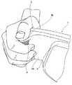
図1(a)は生体インピーダンス測定用ハンドユニット1の正面側斜視図、図1(b)はその背面側斜視図である。図2(a)はハンドユニット1の平面図、図2(b)は(a)の正面図、図3(a)は図2(b)の側面図である。 1A is a front perspective view of the bioimpedance measurement hand unit 1, and FIG. 1B is a rear perspective view thereof. 2A is a plan view of the hand unit 1, FIG. 2B is a front view of FIG. 2A, and FIG. 3A is a side view of FIG.
ハンドユニット1は、横長四角形状に形成されて、両端部分に、左手用の把持部(グリップ)2と右手用の把持部(グリップ)3とをそれぞれ備えるとともに、両把持部2,3の平坦突出部2a,3aの間は、連結部材4で一体的に連結されている。 The hand unit 1 is formed in a horizontally-long rectangular shape, and is provided with a left-hand gripping part (grip) 2 and a right-hand gripping part (grip) 3 at both ends, and the two
各把持部2,3は、手の指全体で握り可能な略円柱状に形成されて、各把持部2,3の人差し指と中指と薬指と小指の指先腹部が接触する部位〔図1(b)の全高に亘ってクロスハッチングで示す部位〕に印加電極6が取付けられ、親指側の掌腹部が接触する部位〔図1(a)および図2(b)の全高に亘ってクロスハッチングで示す部位〕に測定電極7が取付けられている。 Each of the
印加電極取付け部位と測定電極取付け部位との間の把持部2,3には、ほぼ真横に延在するように平坦突出部2a,3aが形成されている。
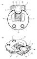
各把持部2,3の上面には、把持部2,3を把持した時に、親指の指先腹部を置くための偏平な親指置き部2b,3bが形成されている。 Flat thumb rests 2b and 3b for placing the fingertip abdomen of the thumb when the
両把持部2,3の平坦突出部2a,3aの間を一体的に連結する連結部材4は、体脂肪率等を表示する液晶ディスプレイ等の表示部4Aと、身長・体重・性別等を入力する各種スイッチ8が配列された操作部4Bとで構成されて、表示部4Aと操作部4Bは、両把持部2,3を把持した使用者の顔面側に配置されている。なお、各種スイッチ8の一部は、平坦突出部2a,3aにも配列することができる。 The connecting
前記のように生体インピーダンス測定用ハンドユニット1を構成すれば、印加電極取付け部位と測定電極取付け部位との間の把持部2,3からほぼ真横に延在する平坦突出部2a,3aの間が連結部材4で連結されているから、図4のように、手首全体を自然に内側に曲げた状態で把持部2,3を把持できるので、親指側の掌腹部が測定電極7に安定に接触するとともに、親指以外の指の指先腹部が印加電極6に安定に接触するようになる。 If the bioimpedance measuring hand unit 1 is configured as described above, the space between the
加えて、把持部2,3の上面に、親指の指先腹部を置くための親指置き部2b,3bが形成されているから、図5のように、この親指置き部2,3に親指を置くことで、把持部2,3をより強く把持できるので、親指側の掌腹部が測定電極7により安定に接触するとともに、親指以外の指の指先腹部が印加電極6により安定に接触するようになる。 In addition, since
また、把持部2,3の平坦突出部2a,3aは、親指の先端が印加電極6に接触することを完全にブロック(阻止)するとともに、親指以外の指の先端が測定電極7に接触することを完全にブロック(阻止)することができる。 Further, the
さらに、体脂肪率等を表示する表示部4Aと、身長・体重・性別等を入力する操作部4Bとを使用者の顔面側に向けた状態で両把持部2,3の間に設けることで、視認性や操作性が向上するようになる。 Furthermore, a
また、図3(b)のように、各把持部2,3の親指置き部2b,3bの上面に、親指を置くことを促す親指マーク(クロスハッチングで示す。)を施すことで、親指置き部2b,3bに親指を置くことを促すことができる。 Further, as shown in FIG. 3B, a thumb mark (indicated by cross-hatching) for urging the user to place the thumb is provided on the upper surface of the
前記実施形態は、ハンドユニット1自体で体脂肪率等を測定するものであったが、図6に示すように、体重計12を別に設けて、この体重計12とハンドユニット1とを電気コード等で電気的に接続することでリンクさせるとともに、体重計12の前部にハンドユニット1を着脱自在に取付けられるようにしても良い。 In the above embodiment, the body fat percentage and the like are measured by the hand unit 1 itself. However, as shown in FIG. 6, a
そして、この体組成体重計12に使用者が左右の足を乗せると、その体重がハンドユニット1の表示部4Aで表示されるようになる。なお、体重計12がハンドユニット1にリンクしていれば、ハンドユニット1の操作部4Bで使用者の体重を入力する必要は無い。 Then, when the user puts the left and right feet on the body
また、体重計12の左右の足を乗せる部分には、印加電極13と測定電極14をそれぞれ設けて、体重計12から取り外したハンドユニット1の把持部2,3を左右の手で把持した使用者が体重計12に乗れば、ハンドユニット1側の印加電極6と測定電極7との間で手の生体インピーダンスを測定することと相俟って、体重計12側の印加電極13と測定電極14との間で足の生体インピーダンスを測定することで、体脂肪率等をより正確に測定することができる。なお、体重計12側でも生体インピーダンスを測定すれば、ハンドユニット1側に印加電極6と測定電極7とを取付けるのは、両把持部2,3のいずれか一方であっても良い。 In addition, the
1 生体インピーダンス測定用ハンドユニット
2,3 把持部
2a,3a 平坦突出部
2b,3b 親指置き部
4 連結部材
4A 表示部
4B 操作部
6 印加電極
7 測定電極DESCRIPTION OF SYMBOLS 1 Bioimpedance
Claims (3)
Translated fromJapanese前記把持部は、左手用の把持部と右手用の把持部とで構成され、少なくとも一方の把持部に前記印加電極と測定電極が取付けられる一方、手首全体を自然に内側に曲げた状態で把持部を把持できるように、前記印加電極取付け部位と測定電極取付け部位とを、互いに周方向に、平面を挟んで所定距離をもたせるように配置して、夫々を湾曲面に形成するとともに、前記印加電極取付け部位と測定電極取付け部位との間の把持部からほぼ真横に延在する平坦突出部が形成され、両把持部の平坦突出部の間が連結部材で連結されているとともに、前記把持部の上面に、親指の指先腹部を置くための親指置き部が形成されていることを特徴とする生体インピーダンス測定用ハンドユニット。A generally cylindrical gripping part that can be gripped by the entire finger of the hand is provided, and an application electrode is attached to the part of the gripping part where the index finger, middle finger, ring finger, and little fingertip abdomen contact, and the palm of the thumb side contacts In the bioimpedance measurement hand unit in which the measurement electrode is attached to the site to be
The gripping portion is composed of a left hand gripping portion and a right hand gripping portion, and the application electrode and the measurement electrode are attached to at least one gripping portion, while the entire wrist is naturally bent inward. Theapplication electrode mounting part and the measurement electrode mounting part are arranged in a circumferential direction so as to have a predetermined distance across a plane so that each part can be gripped, and each of theapplication electrode mounting part and the measurement electrode mounting part is formed on a curved surface. A flat projecting portion extending substantially right from the grip portion between the electrode mounting portion and the measurement electrode mounting portion is formed, and the flat projecting portions of both grip portions are connected by a connecting member. A bio-impedance measuring hand unit, wherein a thumb rest for placing a fingertip abdomen of a thumb is formed on the upper surface of the body.
ることを特徴とする請求項1または2に記載の生体インピーダンス測定用ハンドユニット。The connecting member includes a display unit that displays body fat percentage and the like, and an operation unit that inputs height, weight, sex, and the like. The display unit and the operation unit are on the face side of the user who holds the grip unit. The bioimpedance measurement hand unit according to claim 1, wherein the bioimpedance measurement hand unit is disposed on the body.
Priority Applications (3)
| Application Number | Priority Date | Filing Date | Title |
|---|---|---|---|
| JP2007220784AJP4609463B2 (en) | 2007-08-28 | 2007-08-28 | Hand unit for bioimpedance measurement |
| CN2008102126352ACN101375793B (en) | 2007-08-28 | 2008-08-27 | Handle unit for measuring bio-impedance |
| HK09107650.7AHK1128395B (en) | 2007-08-28 | 2009-08-20 | Hand unit for measuring bioimpedance |
Applications Claiming Priority (1)
| Application Number | Priority Date | Filing Date | Title |
|---|---|---|---|
| JP2007220784AJP4609463B2 (en) | 2007-08-28 | 2007-08-28 | Hand unit for bioimpedance measurement |
Publications (2)
| Publication Number | Publication Date |
|---|---|
| JP2009050508A JP2009050508A (en) | 2009-03-12 |
| JP4609463B2true JP4609463B2 (en) | 2011-01-12 |
Family
ID=40419647
Family Applications (1)
| Application Number | Title | Priority Date | Filing Date |
|---|---|---|---|
| JP2007220784AExpired - Fee RelatedJP4609463B2 (en) | 2007-08-28 | 2007-08-28 | Hand unit for bioimpedance measurement |
Country Status (2)
| Country | Link |
|---|---|
| JP (1) | JP4609463B2 (en) |
| CN (1) | CN101375793B (en) |
Families Citing this family (13)
| Publication number | Priority date | Publication date | Assignee | Title |
|---|---|---|---|---|
| US8870780B2 (en) | 2008-10-15 | 2014-10-28 | The Board Of Trustees Of The Leland Stanford Junior University | Systems and methods for monitoring heart function |
| US9011346B2 (en) | 2011-01-27 | 2015-04-21 | The Board Of Trustees Of The Leland Stanford Junior University | Systems and methods for monitoring the circulatory system |
| ES2398439B1 (en)* | 2011-07-29 | 2014-03-05 | Universitat Politècnica De Catalunya | Method and apparatus for obtaining cardiovascular information by measuring between two extremities |
| US9568354B2 (en) | 2014-06-12 | 2017-02-14 | PhysioWave, Inc. | Multifunction scale with large-area display |
| US9546898B2 (en) | 2014-06-12 | 2017-01-17 | PhysioWave, Inc. | Fitness testing scale |
| US9949662B2 (en) | 2014-06-12 | 2018-04-24 | PhysioWave, Inc. | Device and method having automatic user recognition and obtaining impedance-measurement signals |
| US10130273B2 (en) | 2014-06-12 | 2018-11-20 | PhysioWave, Inc. | Device and method having automatic user-responsive and user-specific physiological-meter platform |
| US9943241B2 (en) | 2014-06-12 | 2018-04-17 | PhysioWave, Inc. | Impedance measurement devices, systems, and methods |
| US9498137B2 (en) | 2014-08-07 | 2016-11-22 | PhysioWave, Inc. | Multi-function fitness scale with display |
| US9693696B2 (en) | 2014-08-07 | 2017-07-04 | PhysioWave, Inc. | System with user-physiological data updates |
| US10945671B2 (en) | 2015-06-23 | 2021-03-16 | PhysioWave, Inc. | Determining physiological parameters using movement detection |
| US10980483B2 (en) | 2015-11-20 | 2021-04-20 | PhysioWave, Inc. | Remote physiologic parameter determination methods and platform apparatuses |
| US11561126B2 (en) | 2015-11-20 | 2023-01-24 | PhysioWave, Inc. | Scale-based user-physiological heuristic systems |
Family Cites Families (5)
| Publication number | Priority date | Publication date | Assignee | Title |
|---|---|---|---|---|
| JP3182991B2 (en)* | 1993-08-12 | 2001-07-03 | オムロン株式会社 | Health management guideline advice device |
| JP3297987B2 (en)* | 1996-12-17 | 2002-07-02 | オムロン株式会社 | Health management guideline advice device |
| JP2001012997A (en)* | 1999-06-30 | 2001-01-19 | Omron Corp | Scale |
| JP2001190512A (en)* | 2000-01-14 | 2001-07-17 | Matsushita Electric Ind Co Ltd | Body fat scale |
| JP3699640B2 (en)* | 2000-08-01 | 2005-09-28 | 株式会社タニタ | Body water content state determination device by multi-frequency bioimpedance measurement |
- 2007
- 2007-08-28JPJP2007220784Apatent/JP4609463B2/ennot_activeExpired - Fee Related
- 2008
- 2008-08-27CNCN2008102126352Apatent/CN101375793B/ennot_activeExpired - Fee Related
Also Published As
| Publication number | Publication date |
|---|---|
| HK1128395A1 (en) | 2009-10-30 |
| JP2009050508A (en) | 2009-03-12 |
| CN101375793A (en) | 2009-03-04 |
| CN101375793B (en) | 2011-06-22 |
Similar Documents
| Publication | Publication Date | Title |
|---|---|---|
| JP4609463B2 (en) | Hand unit for bioimpedance measurement | |
| JP2013226189A (en) | Blood pressure measurement device | |
| CN113631091A (en) | Biological data measuring apparatus, biological data measuring method, and program | |
| CN102631190B (en) | Cardiovascular Monitoring Devices | |
| EP1092389B1 (en) | Bioelectrical impedance measuring apparatus with handgrip | |
| JP2001104273A (en) | Body fat measurement device with weight scale | |
| JP2003159227A (en) | Apparatus for advising guide to health care | |
| JP4423768B2 (en) | Body fat measuring device | |
| HK1128395B (en) | Hand unit for measuring bioimpedance | |
| JP3104554B2 (en) | Grip for health management guideline advice device | |
| JP2000325324A (en) | Somatic fat rate mensuration device | |
| JP4689056B2 (en) | Body fat percentage measuring instrument | |
| JP4056626B2 (en) | Body fat scale and body fat percentage measurement system | |
| JP4647092B2 (en) | Bioimpedance measurement device | |
| JP2007319256A (en) | Portable type electrocardiograph | |
| TW201402068A (en) | Handheld electrocardiogram detection device | |
| JP2002010988A5 (en) | ||
| TWM508304U (en) | Handheld electrocardio detection device | |
| JP2005040187A (en) | Portable electrocardiograph | |
| KR200243938Y1 (en) | A structure of electrodes for the measuring body fat | |
| JP2010220830A (en) | Biological information measuring device | |
| JP4484150B2 (en) | Body composition meter | |
| JP2001000408A5 (en) | ||
| JPH10258041A (en) | Organism information measuring device | |
| KR200260564Y1 (en) | A structure of electrodes for the measuring body fat |
Legal Events
| Date | Code | Title | Description |
|---|---|---|---|
| A621 | Written request for application examination | Free format text:JAPANESE INTERMEDIATE CODE: A621 Effective date:20090410 | |
| A977 | Report on retrieval | Free format text:JAPANESE INTERMEDIATE CODE: A971007 Effective date:20090806 | |
| A131 | Notification of reasons for refusal | Free format text:JAPANESE INTERMEDIATE CODE: A131 Effective date:20090811 | |
| A521 | Request for written amendment filed | Free format text:JAPANESE INTERMEDIATE CODE: A523 Effective date:20091005 | |
| A131 | Notification of reasons for refusal | Free format text:JAPANESE INTERMEDIATE CODE: A131 Effective date:20100413 | |
| A521 | Request for written amendment filed | Free format text:JAPANESE INTERMEDIATE CODE: A523 Effective date:20100609 | |
| TRDD | Decision of grant or rejection written | ||
| A01 | Written decision to grant a patent or to grant a registration (utility model) | Free format text:JAPANESE INTERMEDIATE CODE: A01 Effective date:20100914 | |
| A01 | Written decision to grant a patent or to grant a registration (utility model) | Free format text:JAPANESE INTERMEDIATE CODE: A01 | |
| A61 | First payment of annual fees (during grant procedure) | Free format text:JAPANESE INTERMEDIATE CODE: A61 Effective date:20100927 | |
| FPAY | Renewal fee payment (event date is renewal date of database) | Free format text:PAYMENT UNTIL: 20131022 Year of fee payment:3 | |
| R150 | Certificate of patent or registration of utility model | Free format text:JAPANESE INTERMEDIATE CODE: R150 | |
| LAPS | Cancellation because of no payment of annual fees |