JP4609356B2 - Storage device and access control method thereof - Google Patents
Storage device and access control method thereofDownload PDFInfo
- Publication number
- JP4609356B2 JP4609356B2JP2006081620AJP2006081620AJP4609356B2JP 4609356 B2JP4609356 B2JP 4609356B2JP 2006081620 AJP2006081620 AJP 2006081620AJP 2006081620 AJP2006081620 AJP 2006081620AJP 4609356 B2JP4609356 B2JP 4609356B2
- Authority
- JP
- Japan
- Prior art keywords
- access
- type
- slot
- port
- bandwidth
- Prior art date
- Legal status (The legal status is an assumption and is not a legal conclusion. Google has not performed a legal analysis and makes no representation as to the accuracy of the status listed.)
- Expired - Fee Related
Links
Images


Classifications
- G—PHYSICS
- G06—COMPUTING OR CALCULATING; COUNTING
- G06F—ELECTRIC DIGITAL DATA PROCESSING
- G06F13/00—Interconnection of, or transfer of information or other signals between, memories, input/output devices or central processing units
- G06F13/14—Handling requests for interconnection or transfer
- G06F13/16—Handling requests for interconnection or transfer for access to memory bus
- G06F13/1605—Handling requests for interconnection or transfer for access to memory bus based on arbitration
- G—PHYSICS
- G06—COMPUTING OR CALCULATING; COUNTING
- G06F—ELECTRIC DIGITAL DATA PROCESSING
- G06F13/00—Interconnection of, or transfer of information or other signals between, memories, input/output devices or central processing units
- G06F13/14—Handling requests for interconnection or transfer
- G06F13/20—Handling requests for interconnection or transfer for access to input/output bus
- H—ELECTRICITY
- H04—ELECTRIC COMMUNICATION TECHNIQUE
- H04N—PICTORIAL COMMUNICATION, e.g. TELEVISION
- H04N5/00—Details of television systems
- H04N5/76—Television signal recording
- H04N5/765—Interface circuits between an apparatus for recording and another apparatus
Landscapes
- Engineering & Computer Science (AREA)
- Theoretical Computer Science (AREA)
- Physics & Mathematics (AREA)
- General Engineering & Computer Science (AREA)
- General Physics & Mathematics (AREA)
- Multimedia (AREA)
- Signal Processing (AREA)
- Data Exchanges In Wide-Area Networks (AREA)
- Memory System (AREA)
Description
Translated fromJapanese本発明は、複数のポートにそれぞれタイムスロットを割り当ててアクセスを制御する記憶装置に関し、特に、帯域保障を行うために必要なアクセスの周期がアクセスの種類によって異なる場合のアクセス制御方法に特徴を有するものに関する。 The present invention relates to a storage device that controls access by allocating time slots to a plurality of ports, and particularly has a feature in an access control method in a case where an access cycle required for performing bandwidth guarantee differs depending on the type of access. About things.
単一の記憶装置に対して外部の複数の機器がデータの記憶や再生を行うための方式として、記憶装置に複数のポートを設け、各ポートにそれぞれタイムスロット(当該ポートからのアクセスを受け付ける時間枠)を割り当てて、各機器がそれぞれ別々のポートからこの記憶装置にアクセスするという方式が行われている。 As a method for storing and playing back data to and from a single storage device, a plurality of ports are provided in the storage device, and each port has a time slot (time for accepting access from the port). In this method, each device accesses the storage device from a separate port.
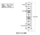
図1は、複数のポートを設けた記憶装置へのアクセスの様子を概念的に示す図である。記憶装置に設けられたn個のポートであるPort1〜Portnに、それぞれタイムスロットが割り当てられる。記憶装置内には、n個のバッファーメモリ21(21(1)〜21(n))が、Port1〜Portnに対応して設けられている。 FIG. 1 is a diagram conceptually illustrating a state of access to a storage device provided with a plurality of ports. A time slot is assigned to each of
Port1〜Portnのうちの或るPortiからデータを記憶する場合には、Portiから入力したデータが、バッファーメモリ21(i)に一時的に蓄積された後、Portiに割り当てたタイムスロットにバッファーメモリ21(i)から読み出されて記憶装置内の記憶媒体20(例えば、半導体記憶装置の一種であるフラッシュメモリ装置の場合にはフラッシュメモリ)に書き込まれる。 When data is stored from a certain Porti among
また、或るPortjからデータを再生する場合には、そのデータが、Portjに割り当てたタイムスロットに記憶媒体20から読み出されてバッファーメモリ21(j)に一時的に蓄積された後、バッファーメモリ21(j)から読み出されてPortjから出力される。 When data is reproduced from a certain Portj, the data is read from the
ところで、このように記憶装置の複数のポートにタイムスロットを割り当てる場合に、記憶装置へのアクセスを帯域保障する(一定の通信量を保障する)ためには、帯域保障しようとするアクセスが行われるポートから、単位時間毎に一定の長さの時間アクセスを行えるようにすることが必要となる。 By the way, when assigning time slots to a plurality of ports of a storage device in this way, in order to guarantee bandwidth to the storage device (guarante a certain amount of communication), access to guarantee the bandwidth is performed. It is necessary to make it possible to access a certain length of time from the port every unit time.
ここで、この帯域保障のために必要な単位時間当たりのアクセス時間長が、アクセスの種類にかかわらず一定である場合には、帯域保障しようとするアクセスが行われる各ポートには、互いに均等な長さのタイムスロットを同じ数だけ割り当てれば足りる(特許文献1,2参照)。 Here, when the access time length per unit time required for guaranteeing the bandwidth is constant regardless of the type of access, the ports to which access to guarantee the bandwidth is performed are equal to each other. It is sufficient to assign the same number of time slots (see
しかし、帯域保障のために必要な単位時間当たりのアクセス時間長は、アクセスの種類によって異なる場合がある。例えば、フラッシュメモリ装置では、或る量のデータを記憶するための所要時間よりも、同じ量のデータを再生するための所要時間が長くなる。したがって、再生のためにアクセスされるポートは、記憶のためにアクセスされるポートよりも、帯域保障のために必要な単位時間当たりのアクセス時間が長くなる。 However, the access time length per unit time necessary for bandwidth guarantee may vary depending on the type of access. For example, in a flash memory device, the time required to reproduce the same amount of data is longer than the time required to store a certain amount of data. Therefore, the port accessed for reproduction has a longer access time per unit time required for bandwidth guarantee than the port accessed for storage.
また、同じくデータを再生する場合でも、例えば転送速度50Mbpsで再生する場合と転送速度30Mbpsで再生する場合とでは、前者のほうが単位時間当たりに再生すべきデータ量が多くなる。したがって、転送速度50Mbpsで再生を行うためにアクセスされるポートは、転送速度30Mbpsで再生を行うためにアクセスされるポートよりも、帯域保障のために必要な単位時間当たりのアクセス時間が長くなる。 Similarly, even when data is reproduced, for example, when the data is reproduced at a transfer rate of 50 Mbps and when the data is reproduced at a transfer rate of 30 Mbps, the former requires a larger amount of data to be reproduced per unit time. Therefore, the port accessed for playback at a transfer rate of 50 Mbps has a longer access time per unit time required for bandwidth guarantee than the port accessed for playback at a transfer rate of 30 Mbps.
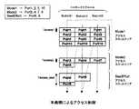
図2は、そのような場合における、従来のアクセス制御方法を示す。ここでは、アクセスモード(アクセスの種類)を、Mode1,Mode2,BestEffortの3種類としている。Mode1,Mode2は、それぞれ帯域保障すべき種類のアクセスであるが、Mode1のほうが、帯域保障のために必要な単位時間当たりのアクセス時間が長くなっている。BestEffortは、ベストエフォート型の(帯域保障はしないが可能な限り高速化する、いわゆる出来高型の)アクセスである。 FIG. 2 shows a conventional access control method in such a case. Here, there are three access modes (access types): Mode1, Mode2, and BestEffort.
そして、ポート数をPort1〜Port10の10本とし、Port1,2,5,10からMode1のアクセスが行われ、Port3,4,7,8からMode2のアクセスが行われ、Port6,9からBestEffortのアクセスが行われるものとしている。 Then, the number of ports is 10 from
Mode1の各ポート(Port1,2,5,10)と、Mode2の各ポート(Port3,4,7,8)には、1個ずつのタイムスロットを割り当てている。Mode1の各ポートのタイムスロットの長さTaccess1と、Mode2の各ポートのタイムスロットの長さTaccess2とは、次のような条件を満たすように設定している。 One time slot is assigned to each port of Mode 1 (
条件:Mode1のアクセスを帯域保障するために必要なアクセス周期(これは、Mode1のポートに対応するバッファーメモリ(図1のバッファーメモリ21)が、アクセス1回当たりに蓄積しなければならないデータ量を、時間の長さに換算したものであるといえるので、Tbuf1と表す)と、Mode2のアクセスを帯域保障するために必要なアクセス周期(同じくTbuf2と表す)とが、
そして、BestEffortのポート(Port6,9)のタイムスロットを末尾に配置し、このBestEffortのポートのタイムスロットの長さTaccess_bestを、全タイムスロットの合計の長さTtotal_accessが下記式の条件を満たすように制御することにより、Mode1のアクセスとMode2のアクセスとを帯域保障している。
しかし、この図2のアクセス制御方法では、仮にMode1はアクセス1回当たりの時間を短くすることによってアクセス周期Tbuf1を短くすることが可能な種類のアクセスであっても、Mode2がアクセス1回当たりの時間を短くできないためにアクセス周期Tbuf2を短くできない種類のアクセスである場合には、上記式(1)の条件から、アクセス周期Tbuf1をアクセス周期Tbuf2とほぼ一致させなければならないので、アクセス周期Tbuf1を短くすることができない。 However, in the access control method of FIG. 2, even if Mode1 is a type of access that can shorten the access cycle Tbuf1 by shortening the time per access, Mode2 is per access. When the access cycle Tbuf2 cannot be shortened because the time cannot be shortened, the access cycle Tbuf1 must be substantially matched with the access cycle Tbuf2 from the condition of the above formula (1). It cannot be shortened.
例えば、フラッシュメモリ装置では、再生のためのアクセスはフラッシュメモリのブロックよりも小さいページ単位で行っても速度がほとんど低下しないのでアクセス1回当たりの時間を短くすることが可能であるが、記憶のためのアクセスを高速に行うためにはブロック単位でアクセスを行う必要があるためアクセス1回当たりの時間を短くできないので、Mode1が再生のためのアクセスでありMode2が記憶のためのアクセスであるときが、こうした場合に該当する。 For example, in a flash memory device, the speed for one access can be shortened because the speed of the access for reproduction is almost the same even if it is performed in units of pages smaller than the block of the flash memory. In order to perform high-speed access for access, it is necessary to perform access in units of blocks, so the time per access cannot be shortened. Therefore, when
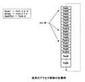
図3は、図2のアクセス制御方法による、Mode1,Mode2のポートに対応するバッファーメモリ(図1のバッファーメモリ21)のデータ蓄積量であるバッファー量の推移を示す図である。仮にMode1がアクセス1回当たりの時間を短くすることが可能な種類のアクセスであっても、Mode2がアクセス1回当たりの時間を短くできない種類のアクセスである場合には、アクセス周期Tbuf1を短くすることができないので、Mode1のアクセスが繰り返される間隔が長くなる。そのため、Mode1のアクセスを要求してからそのアクセスが実行されるまでの遅延時間が大きく(最大でTbuf1に)なるので、外部の機器から見て、Mode1のアクセスを行う際の記憶装置の反応が遅くなってしまう。 FIG. 3 is a diagram showing the transition of the buffer amount, which is the amount of data stored in the buffer memory (
また、Mode1のアクセスが繰り返される間隔が長くなることから、図3にも表れているように、Mode1のポートに対応するバッファーメモリのバッファー量の最大値Dbuf1が大きくなる。そのため、Mode1のポートに対応するバッファーメモリをオーバーフローさせたりアンダーフローさせないためのバッファー容量を、この最大値Dbuf1に合せて大きくしなければならない。 Further, since the interval at which the access of
これに対し、図4は、Mode1がアクセス1回当たりの時間を短くすることが可能な種類のアクセスである場合の、アクセス制御方法の改善例を示す。この例では、Mode1のポート(Port1,2,5,10)には、Ndiv個(Ndivは2以上の整数であり、図ではNdiv=3)ずつのタイムスロットを割り当てている。Mode1の各ポートのタイムスロットの長さTaccess1と、Mode2の各ポートのタイムスロットの長さTaccess2とは、前述のMode1のアクセスを帯域保障するためのアクセス周期Tbuf1と、Mode2のアクセスを帯域保障するためのアクセス周期Tbuf2とが、下記式の条件を満たすように設定している。
これにより、Mode1の各ポートのタイムスロットの長さTaccess1は、図2の場合よりも短くなっている。 As a result, the time slot length Taccess1 of each port of Mode1 is shorter than in the case of FIG.
そして、BestEffortのポート(Port6,9)のタイムスロットを末尾に配置し、このBestEffortのポートのタイムスロットの長さTaccess_bestを、全タイムスロットの合計の長さTtotal_accessが下記式の条件を満たすように制御することにより、Mode1のアクセスとMode2のアクセスとを帯域保障している。
図5は、この改善例による、Mode1,Mode2のポートに対応するバッファーメモリのバッファー量の推移を示す図である。この改善例では、Mode1のアクセスが繰り返される間隔は、Mode2のアクセスが繰り返される間隔よりは短くなるものの、不均一になってしまう。そして、アクセスの遅延時間はワーストケース(アクセスの間隔が最も長い部分)で見積もらなければならないので、図2のアクセス制御方法の場合(図3)よりは改善されるものの、やはり遅延時間が大きくなってしまう。 FIG. 5 is a diagram showing the transition of the buffer amount of the buffer memory corresponding to the ports of
また、Mode1のポートに対応するバッファーメモリのバッファー量も、図2のアクセス制御方法の場合よりは小さくなるものの、図5に表れているように、やはりこのワーストケースの部分で他の部分よりも大きな最大値Dbuf1をとるようになる。そのため、Mode1のポートに対応するバッファーメモリをオーバーフローさせたりアンダーフローさせないためのバッファー容量を、やはりこの最大値Dbuf1に合せて大きくしなければならない。 Further, although the buffer amount of the buffer memory corresponding to the
本発明は、上述の点に鑑み、このMode1とMode2とのように、帯域保障を行うために必要なアクセス周期が異なる2種類のアクセスを複数のポートから記憶装置に対して行う場合に、このアクセス周期が短いほうの種類のアクセスについての遅延時間やバッファー容量を小さくすることを課題とする。 In the present invention, in view of the above points, when two types of access having different access cycles necessary for performing bandwidth guarantee are performed from a plurality of ports to a storage device, as in
上記課題を解決するために、本発明に係る記憶装置は、
複数のポートからアクセスされる記憶装置において、
第1の種類のアクセスと、帯域保障を行うために必要なアクセス周期がこの第1の種類のアクセスよりも長い第2の種類のアクセスとのうち、第1の種類のアクセスが行われる各ポートに割り当てる1個のタイムスロットの長さTaccess1と、第2の種類のアクセスが行われる各ポートに割り当てる1個のタイムスロットの長さTaccess2とを、
第1の種類のアクセスを帯域保障するために必要なアクセス周期×M≒第2の種類のアクセスを帯域保障するために必要なアクセス周期(但しMは2以上の整数)
の条件を満たすように設定し、
第1の種類のアクセスを帯域保障するために必要なアクセス周期以内に収めた長さのスロットユニットを、第2の種類のアクセスを帯域保障するために必要なアクセス周期以内に収めるように時間軸上でこのM本繋げることによってトータルスケジュールを構成し、
各スロットユニットに、時間軸で早い方から順に第1の種類のアクセススロットエリア,第2の種類のアクセススロットエリアを設け、
複数のポートのうち、この第1の種類のアクセスが行われるポートには、1つのこのスロットユニット毎に、この第1の種類のアクセススロットエリアにこの長さTaccess1の1個のタイムスロットを割り当て、
この第2の種類のアクセスが行われるポートには、このトータルスケジュール1周期で1つだけのスロットユニットのこの第2の種類のアクセススロットエリアに、この長さTaccess2の1個のタイムスロットを割り当てるアクセス制御手段を備えたことを特徴とする。In order to solve the above problems, a storage device according to the present invention provides:
In storage devices accessed from multiple ports,
Of the first type of access and the second type of access in which the access cycle necessary for performing bandwidth guarantee is longer thanthe first type of access, each port where the first type of access is performed A time
Access cycle necessary to guarantee the bandwidth of the first type of access × M≈Access cycle necessary to guarantee the bandwidth of the second type of access (where M is an integer of 2 or more)
To meet the conditions of
The time axis is set so that the slot unit having a length within the access cycle necessary to guarantee the bandwidth of the first type of access is within the access cycle necessary to guarantee the bandwidth of the second type of access. The total schedule is configured by connectingthese M books above,
Each slot unit is provided with a first type access slot area and a second type access slot area in order from the earliest on the time axis,
Among the plurality of ports, one time slotof this length Taccess1 is allocated tothe first type access slot area for each slot unit for the port where the first type access is performed. ,
One time slot ofthis length Taccess2 is allocated tothe second type access slot area ofonly one slot unit inone cycle of the total schedule for the port where the second type access is performed. An access control means is provided.
この記憶装置では、帯域保障のために必要なアクセス周期が短い第1の種類のアクセスと、帯域保障のために必要なアクセス周期が長い第2の種類のアクセスとのうち、第1の種類のアクセスが行われる各ポートに割り当てる1個のタイムスロットの長さTaccess1と、第2の種類のアクセスが行われる各ポートに割り当てる1個のタイムスロットの長さTaccess2とが、
第1の種類のアクセスを帯域保障するために必要なアクセス周期×M≒第2の種類のアクセスを帯域保障するために必要なアクセス周期(但しMは2以上の整数)
の条件を満たすように設定される。
そして、第1の種類のアクセスを帯域保障するために必要な短いアクセス周期以内に収まる長さのスロットユニットを、第2の種類のアクセスを帯域保障するために必要な長いアクセス周期以内に収まるように時間軸上でこのM本繋げることによって、トータルスケジュールが構成される。
そして、各スロットユニットに、時間軸で早い方から順に第1の種類のアクセススロットエリア,第2の種類のアクセススロットエリアが設けられる。In this storage device, the first type of access of the first type having a short access cycle necessary for bandwidth guarantee and the second type of access having a long access cycle necessary for bandwidth guarantee ofthe first type The
Access cycle necessary to guarantee the bandwidth of the first type of access × M≈Access cycle necessary to guarantee the bandwidth of the second type of access (where M is an integer of 2 or more)
Is set so as to satisfy the following conditions.
Then, a slot unit having a length that can be accommodated within a short access cycle necessary for guaranteeing the bandwidth of the first type of access is accommodated within a long access cycle necessary for guaranteeing the bandwidth of the second type of access. A total schedule is formed by connectingthese M lines on the time axis.
Each slot unit is provided with a first type access slot area and a second type access slot area in order from the earliest on the time axis.
そして、複数のポートのうち、第1の種類のアクセスが行われるポートには、1つのスロットユニット毎に、この第1の種類のアクセススロットエリアにこの長さTaccess1の1個のタイムスロットを割り当てることにより、トータルスケジュール1周期当たり、ほぼ均一な間隔で複数のタイムスロットが割り当てられる。また、第2の種類のアクセスが行われるポートには、トータルスケジュール1周期で1つだけのスロットユニットのこの第2の種類のアクセススロットエリアに、この長さTaccess2の1個のタイムスロットを割り当てることにより、トータルスケジュール1周期当たり1個だけのタイムスロットが割り当てられる。Of the plurality of ports, one time slotof this length Taccess1 is allocated tothe first type access slot area for each slot unit for the port where the first type access is performed. As a result, a plurality of time slots are allocated at substantially uniform intervals per period of the total schedule.Further, one time slot of this length Taccess2 is allocated to the second type access slot area of only one slot unit in one cycle of thetotal schedule for the port where the second type access is performed.As a result, only one time slot is allocated per cycleof the total schedule.
したがって、第1の種類のアクセスが繰り返される間隔は、第2の種類のアクセスが繰り返される間隔よりも短く、且つ、ほぼ均一な間隔になる(すなわち、ワーストケースでも間隔が短くなる)。これにより、第1の種類のアクセス(帯域保障のために必要なアクセス周期が短いほうの種類のアクセス)を要求してからそのアクセスが実行されるまでの遅延時間が短くなる。その結果、外部の機器から見て、帯域保障のために必要なアクセス周期が短いほうの種類のアクセスを行う際の記憶装置の反応が速くなる。 Therefore, the interval at which the first type access is repeated is shorter than the interval at which the second type access is repeated, and is substantially uniform (that is, the interval is shortened even in the worst case). As a result, the delay time from when the first type of access (the type of access having the shorter access cycle necessary for bandwidth guarantee) to the execution of the access is shortened. As a result, the response of the storage device when performing access of the type having a shorter access cycle necessary for bandwidth guarantee as viewed from an external device becomes faster.
また、このように第1の種類のアクセスが繰り返される間隔が短く且つほぼ均一であることから、第1の種類のアクセス(帯域保障のために必要なアクセス周期が短いほうの種類のアクセス)を行うポートに対応して設けられるバッファーメモリのバッファー量の最大値が小さくなる。これにより、このバッファーメモリをオーバーフローさせたりアンダーフローさせないためのバッファー容量を小さくすることができる。 In addition, since the interval at which the first type of access is repeated is short and substantially uniform, the first type of access (the type of access having a shorter access cycle necessary for bandwidth guarantee) is performed. The maximum buffer amount of the buffer memory provided corresponding to the port to be performed is reduced. As a result, the buffer capacity for preventing the buffer memory from overflowing or underflowing can be reduced.
次に、本発明に係るアクセス制御方法は、
複数のポートからアクセスされる記憶装置内でアクセス制御手段が実行するアクセス制御方法において、
第1の種類のアクセスと、帯域保障を行うために必要なアクセス周期がこの第1の種類のアクセスよりも長い第2の種類のアクセスとのうち、第1の種類のアクセスが行われる各ポートに割り当てる1個のタイムスロットの長さTaccess1と、第2の種類のアクセスが行われる各ポートに割り当てる1個のタイムスロットの長さTaccess2とを、
第1の種類のアクセスを帯域保障するために必要なアクセス周期×M≒第2の種類のアクセスを帯域保障するために必要なアクセス周期(但しMは2以上の整数)
の条件を満たすように設定し、
第1の種類のアクセスを帯域保障するために必要なアクセス周期以内に収めた長さのスロットユニットを、第2の種類のアクセスを帯域保障するために必要なアクセス周期以内に収めるように時間軸上でM本繋げることによってトータルスケジュールを構成し、
各スロットユニットに、時間軸で早い方から順に第1の種類のアクセススロットエリア,第2の種類のアクセススロットエリアを設け、
複数のポートのうち、この第1の種類のアクセスが行われるポートには、1つのこのスロットユニット毎に、この第1の種類のアクセススロットエリアにこの長さTaccess1の1個のタイムスロットを割り当て、
この第2の種類のアクセスが行われるポートには、このトータルスケジュール1周期で1つだけのスロットユニットのこの第2の種類のアクセススロットエリアに、この長さTaccess2の1個のタイムスロットを割り当てることを特徴とする。Next, an access control method according to the present invention includes:
In an access control method executed by an access control means in a storage device accessed from a plurality of ports,
Of the first type of access and the second type of access in which the access cycle necessary for performing bandwidth guarantee is longer thanthe first type of access, each port where the first type of access is performed A time
Access cycle necessary to guarantee the bandwidth of the first type of access × M≈Access cycle necessary to guarantee the bandwidth of the second type of access (where M is an integer of 2 or more)
To meet the conditions of
The time axis is set so that the slot unit having a length within the access cycle necessary to guarantee the bandwidth of the first type of access is within the access cycle necessary to guarantee the bandwidth of the second type of access. Configure a total schedule by connectingM books above,
Each slot unit is provided with a first type access slot area and a second type access slot area in order from the earliest on the time axis,
Among the plurality of ports, one time slotof this length Taccess1 is allocated tothe first type access slot area for each slot unit for the port where the first type access is performed. ,
One time slot ofthis length Taccess2 is allocated tothe second type access slot area ofonly one slot unit inone cycle of the total schedule for the port where the second type access is performed. It is characterized by that.
このアクセス制御方法は、前述の本発明に係る記憶装置によるアクセス制御方法に該当するものであり、帯域保障のために必要なアクセス周期が短いほうの種類のアクセスを要求してからそのアクセスが実行されるまでの遅延時間を短くすることができるとともに、帯域保障のために必要なアクセス周期が短いほうの種類のアクセスを行うポートに対応して設けられるバッファーメモリの容量を小さくすることができる。 This access control method corresponds to the above-described access control method by the storage device according to the present invention, and the access is executed after requesting the access with the shorter access cycle necessary for bandwidth guarantee. In addition to shortening the delay time until the access is made, it is possible to reduce the capacity of the buffer memory provided corresponding to the port that performs the type of access having a shorter access cycle necessary for bandwidth guarantee.
本発明によれば、帯域保障を行うために必要なアクセス周期が異なる2種類のアクセスを複数のポートから記憶装置に対して行う場合に、帯域保障のために必要なアクセス周期が短いほうの種類のアクセスを要求してからそのアクセスが実行されるまでの遅延時間が短くなるので、外部の機器から見て、帯域保障のために必要なアクセス周期が短いほうの種類のアクセスを行う際の記憶装置の反応が速くなるという効果が得られる。 According to the present invention, when two types of accesses having different access cycles necessary for bandwidth guarantee are performed from a plurality of ports to a storage device, the type having the shorter access cycle required for bandwidth guarantee The delay time from when an access is requested to when the access is executed is shortened, so the memory when performing the type of access with the shorter access cycle required for bandwidth guarantee as viewed from the external device The effect that the reaction of the apparatus becomes faster is obtained.
また、帯域保障のために必要なアクセス周期が短いほうの種類のアクセスを行うポートに対応して設けられるバッファーメモリの容量を小さくすることができるという効果が得られる。 In addition, it is possible to reduce the capacity of the buffer memory provided corresponding to the port that performs the type of access having a shorter access cycle necessary for bandwidth guarantee.
以下、本発明の実施の形態を図面を用いて説明する。図6は、本発明を適用したフラッシュメモリ装置の全体構成を示すブロック図である。このフラッシュメモリ装置には、フラッシュメモリ1と、スロットアクセスコントローラ2と、n個のバッファーメモリ3(3(1)〜3(n))と、n個のポート入出力プロセッサ4(4(1)〜4(n))とが設けられている。 Hereinafter, embodiments of the present invention will be described with reference to the drawings. FIG. 6 is a block diagram showing the overall configuration of a flash memory device to which the present invention is applied. The flash memory device includes a
スロットアクセスコントローラ2は、このフラッシュメモリ装置に設けられた複数のポートであるPort1〜Portnからのフラッシュメモリ1に対するアクセスを、タイムスロットを割り当てることによって制御するコントローラである。 The
バッファーメモリ3(1)〜3(n)と、ポート入出力プロセッサ4(1)〜4(n)とは、Port1〜Portnにそれぞれ1対1に対応している。各ポート入出力プロセッサ4(1)〜4(n)は、Port1〜Portnから入力したデータをフラッシュメモリ1への記憶に適した形式のデータに変換するための信号処理(例えば圧縮)を行う役割と、バッファーメモリ3(1)〜3(n)から送られたデータをPort1〜Portnからの出力用に信号処理する(例えば圧縮データを伸張する)役割とを果たす。 The buffer memories 3 (1) to 3 (n) and the port input / output processors 4 (1) to 4 (n) have a one-to-one correspondence with Port1 to Portn, respectively. Each port input / output processor 4 (1) to 4 (n) performs signal processing (for example, compression) for converting data input from
Port1〜Portnのうちの或るPortiからデータを記憶する場合には、Portiから入力したデータが、ポート入出力プロセッサ4(i)の処理を経て、バッファーメモリ3(i)に一時的に蓄積される。そして、バッファーメモリ3(i)に蓄積されたデータが、スロットアクセスコントローラ2によってPortiに割り当てられたタイムスロットに、バッファーメモリ3(i)から読み出され、スロットアクセスコントローラ2からフラッシュメモリ1に転送されてフラッシュメモリ1に書き込まれる。 When data is stored from a certain Porti among Port1 to Portn, the data input from Porti is temporarily stored in the buffer memory 3 (i) through the processing of the port input / output processor 4 (i). The Then, the data stored in the buffer memory 3 (i) is read from the buffer memory 3 (i) to the time slot assigned to Porti by the
また、或るPortjからデータを再生する場合には、そのデータが、スロットアクセスコントローラ2によってPortjに割り当てられたタイムスロットに、フラッシュメモリ1から読み出され、スロットアクセスコントローラ2からバッファーメモリ3(j)に転送されてバッファーメモリ3(j)に一時的に蓄積される。そして、バッファーメモリ3(i)に蓄積されたデータが、バッファーメモリ3(j)から読み出され、ポート入出力プロセッサ4(j)の処理を経てPortiから出力される。 When data is reproduced from a certain port j, the data is read from the
図7は、このスロットアクセスコントローラ2が実行するアクセス制御方法を示す図である。ここでは、アクセスモード(アクセスの種類)を、Mode1,Mode2,BestEffortの3種類としている。Mode1,Mode2は、それぞれ帯域保障すべき種類のアクセスであるが、Mode1のほうが、帯域保障のために必要な単位時間当たりのアクセス時間が長くなっている。BestEffortは、ベストエフォート型の(帯域保障はしないが可能な限り高速化する、いわゆる出来高型の)アクセスである。Mode1の例としては、リアルタイム性を要求されるデータの再生のためのアクセスが挙げられる。Mode2の例としては、リアルタイム性を要求されるデータの記憶のためのアクセスが挙げられる。BestEffortの例としては、リアルタイム性を要求されない、ネットワーク経由でのファイル転送によるデータの記憶または再生のためのアクセスが挙げられる。 FIG. 7 is a view showing an access control method executed by the
また、ここでは、ポート数をPort1〜Port10の10本とし、Port1,2,5,10からMode1のアクセスが行われ、Port3,4,7,8からMode2のアクセスが行われ、Port6,9からBestEffortのアクセスが行われるものとしている。なお、どのポートからどのアクセスモードのアクセスが行われるかは、予め固定しておいてもよいし、動的に変化させてもよい。 Also, here, the number of ports is 10 from
Mode1の各ポート(Port1,2,5,10)に割り当てる1個のタイムスロットの長さTaccess1と、Mode2の各ポート(Port3,4,7,8)に割り当てる1個のタイムスロットの長さTaccess2とは、次のような条件を満たすように設定している。 The
条件:Mode1のアクセスを帯域保障するために必要なアクセス周期(これは、Mode1のポートに対応するバッファーメモリ(図6のバッファーメモリ3)が、アクセス1回当たりに蓄積しなければならないデータ量を、時間の長さに換算したものであるといえるので、Tbuf1と表す)と、Mode2のアクセスを帯域保障するために必要なアクセス周期(同じくTbuf2と表す)とが、
但し、Mは2以上の整数であり、図ではM=3である。Condition: Access cycle necessary to guarantee bandwidth of
However, M is an integer greater than or equal to 2, and M = 3 in the figure.
例えばMode1,Mode2が前述のようにそれぞれリアルタイム性を要求されるデータの再生,記憶のためのアクセスである場合には、具体的には、Taccess1は、フラッシュメモリ1に対してブロックよりも小さいページ単位でアクセスしてデータを再生するための時間長に設定し、Taccess2は、フラッシュメモリ1に対してブロック単位でアクセスしてデータを記憶するための時間長に設定することができる。 For example, when
そして、M本(図では3本)のスロットユニットであるSlotUnit1〜SlotUnit3を時間軸上で繋げることによって、トータルスケジュールを構成する(図では、図示の都合上、時間軸を、SlotUnit1の末尾から図の斜め上方向に跳んでSlotUnit2の先頭に移り、SlotUnit2の末尾から図の斜め上方向に跳んでSlotUnit3の先頭に移るように、3つに分けて描いている)。 A total schedule is constructed by connecting
各SlotUnit1〜SlotUnit3には、先頭(時間軸で早い方)から順に、Mode1アクセススロットエリア,Mode2アクセススロットエリア,BestEffortアクセススロットエリアを設ける。 Each SlotUnit1 to SlotUnit3 is provided with a Mode1 access slot area, a Mode2 access slot area, and a BestEffort access slot area in order from the head (whichever is earlier on the time axis).
そして、Mode1の各ポート(Port1,2,5,10)については、ポートがオープンされた時点で、各SlotUnit1〜SlotUnit3のMode1アクセススロットエリアに、前述の長さTaccess1のタイムスロットを1個ずつ(トータルスケジュール1周期でM=3個)割り当てる。 For each port of Mode 1 (
また、Mode2の各ポート(Port3,4,7,8)については、ポートがオープンされた時点で、SlotUnit1から順に、Mode2アクセススロットエリアに前述の長さTaccess2のタイムスロットを1個(トータルスケジュール1周期で1個だけ)割り当てる。図では、最初にPort3がオープンされてSlotUnit1のMode2アクセススロットエリアにタイムスロットが割り当てられ、2番目にPort4がオープンされてSlotUnit2のMode2アクセススロットエリアにタイムスロットが割り当てられ、3番目にPort7がオープンされてSlotUnit3のMode2アクセススロットエリアにタイムスロットが割り当てられ、4番目にPort8がオープンされて再びSlotUnit1のMode2アクセススロットエリアに(Port3のタイムスロットに続く時間位置に)タイムスロットが割り当てられている。 For each port (
また、各SlotUnit1〜SlotUnit3のBestEffortアクセススロットエリアに割り当てるタイムスロットの長さTaccess_bestは、下記式の条件を満たすように制御する。
図では、この式(6)の条件を満たすように、BestEffortのポート(Port6,9)のうちのPort6のタイムスロットが、SlotUnit1のBestEffortアクセススロットエリアに割り当てられるとともに、Port9のタイムスロットが、SlotUnit1のBestEffortアクセススロットエリア(Port6のタイムスロットに続く時間位置)とSlotUnit2のBestEffortアクセススロットエリアとにまたがって割り当てられている。 In the figure, the Port 6 time slot of the Ports of BestEffort (Ports 6 and 9) is assigned to the BestEffect access slot area of SlotUnit1 and the Port9 time slot is set to SlotUnit1 so as to satisfy the condition of Expression (6). Assigned to the best impact access slot area (time position following the time slot of port 6) and the best effort access slot area of
上記式(6)の条件を満たすことにより、Mode1の各ポート(Port1,2,5,10)に、帯域保障のために必要なアクセス周期Tbuf1以内の間隔でタイムスロットが割り当てられるので、Mode1のアクセスが帯域保障される。 By satisfying the condition of the above equation (6), time slots are allocated to the ports (
また、上記式(5)と式(6)との関係から、トータルスケジュール1周期の長さTotal_Scheduleは、下記式の条件を満たすようになる。
したがって、Mode2の各ポート(Port3,4,7,8)にも、帯域保障のために必要なアクセス周期Tbuf2以内の間隔でタイムスロットが割り当てられるので、Mode2のアクセスも帯域保障される。 Accordingly, since the time slots are allocated to the ports (
図8は、図7のアクセス制御方法による、Mode1,Mode2の各ポートに対応するバッファーメモリ(図6のバッファーメモリ3)のデータ蓄積量であるバッファー量の推移を示す図である。Mode1のアクセスが繰り返される間隔は、Mode2のアクセスが繰り返される間隔よりも短く、且つ、ほぼ均一な間隔になっている(すなわち、ワーストケースでも間隔が短くなっている)。 FIG. 8 is a diagram showing the transition of the buffer amount that is the amount of data stored in the buffer memory (
このように、Mode1のアクセスが繰り返される間隔がほぼ均一な短い間隔になることにより、次のような2つの点でメリットが生まれる。 As described above, since the interval at which the access of
1つ目のメリットは、図6のバッファーメモリ3がMode1のアクセスを要求してからそのアクセスが実行されるまでの遅延時間が短くなることである。 The first merit is that the delay time from when the
例えば、ビデオデータのシャトル再生では、外部の機器でのシャトル操作(2倍速,4倍速,8倍速といった再生速度の選択操作)に応じて、バッファーメモリ3が、フラッシュメモリ1からのデータの読出しアドレスを決定し、そのアドレスのデータを読み出すためのアクセス要求をスロットアクセスコントローラ2に対して行う。そして、スロットアクセスコントローラ2がその要求を処理することにより、シャトル再生のためのデータの読み出しが実現される。 For example, in shuttle playback of video data, the
したがって、バッファーメモリ3がMode1のアクセスとしてシャトル再生のためのアクセスを要求してから、そのアクセスが実行されるまでの遅延時間が短くなるので、シャトル操作を行う外部の機器から見て、シャトル操作に対するフラッシュメモリ装置のポートからのビデオデータ出力の反応が早くなる(シャトルレスポンスが向上する)というメリットが生まれる。 Accordingly, since the delay time from when the
2つ目のメリットは、図8にも表れているように、Mode1のポートに対応するバッファーメモリ3のバッファー量の最大値Dbuf1が小さくなり、その結果、Mode1のポートに対応するバッファーメモリ3をオーバーフローさせたりアンダーフローさせないためのバッファー容量を小さくできることである。 As shown in FIG. 8, the second merit is that the maximum value Dbuf1 of the buffer amount of the
最後に、図7のアクセス制御方法を実現するためのスロットアクセスコントローラ2の構成例を、図9を用いて説明する。スロットアクセスコントローラ2には、スロットコントローラ11と、フラッシュメモリ1(図6)にアクセスするためのDMA(ダイレクトメモリアクセス)コントローラ12と、バッファーメモリ3(1)〜3(n)(図6)とのインタフェースであるn個のバッファーインタフェース13(13(1)〜13(n))とが設けられている。 Finally, a configuration example of the
スロットコントローラ11には、Mode1スロット割り当て部14と、Mode2スロット割り当て部15と、BestEffortスロット割り当て部16と、M個(図7の場合にはM=3)のSlotUnit1スケジューラ17(1)〜SlotUnitMスケジューラ17(M)と、スロットユニットスイッチ18とが設けられている。 The slot controller 11 includes a Mode1
Port1〜Portnのうちのいずれかのポートがオープンして、そのポートに対応するバッファーメモリ3からの要求がバッファーインタフェース13を介してスロットコントローラ11に送られる毎に、スロットコントローラ11では、その要求の内容から、そのポートがMode1,Mode2,BestEffortのうちのいずれのアクセスモードのポートであるかを判別する。 Each time one of the ports Port1 to Portn is opened and a request from the
そして、Mode1のポートである場合には、Mode1スロット割り当て部14が、図7に例示したようにM本のスロットユニットSlotUnit1〜SlotUnitMのMode1アクセススロットエリアにそれぞれそのポートのタイムスロットを割り当てる処理を行う。 If the port is a Mode1 port, the Mode1
他方、Mode1のポートである場合には、Mode2スロット割り当て部15が、図7に例示したように1本ずつのスロットユニットのMode2アクセススロットエリアに順番にそのポートのタイムスロットを割り当てる処理を行う。 On the other hand, if it is a port of
他方、BestEffortのポートである場合には、BestEffortスロット割り当て部16が、図7に示したようにスロットユニットのBestEffortアクセススロットエリアにそのポートのタイムスロットを割り当てる処理を行う。 On the other hand, if it is a port of BestEffort, the BestEffort
SlotUnit1スケジューラ17(1)〜SlotUnitMスケジューラ17(M)は、これらのスロット割り当て部14〜16の割り当て結果に基づいて、図7に例示したようにそれぞれ1本ずつのスロットユニットSlotUnit1〜SlotUnitMをスケジューリングする処理を行う。 The SlotUnit1 scheduler 17 (1) to SlotUnitM scheduler 17 (M) schedules one slot unit SlotUnit1 to SlotUnitM as illustrated in FIG. 7 based on the allocation results of these
スロットユニットスイッチ18は、SlotUnit1スケジューラ17(1)〜SlotUnitMスケジューラ17(M)のスケジューリング結果(すなわちトータルスケジュール1周期分のスケジューリング結果)に基づき、各バッファーメモリ3からバッファーインタフェース13を介してDMAコントローラ12に送られるデータを1つずつ切り換えてDMAコントローラ12からフラッシュメモリ1に転送させる制御と、フラッシュメモリ1からDMAコントローラ12に送られるデータをどのバッファーインタフェース13に送るかを切り換える制御とを行う。 The
なお、以上の説明では、Mode1,Mode2の例として、それぞれデータの再生のためのアクセス,データの記憶のためのアクセスを挙げた。しかし、本発明は、これに限らず、帯域保障を行うために必要なアクセス周期が異なる2種類のアクセスを複数のポートから行うあらゆるケースに適用することができる。 In the above description, as examples of
また、以上の説明ではフラッシュメモリ装置に本発明を適用している。しかし、本発明は、これに限らず、フラッシュメモリ装置以外の記憶装置に対して、帯域保障を行うために必要なアクセス周期が異なる2種類のアクセスを複数のポートから行う場合にも適用することができる。 In the above description, the present invention is applied to a flash memory device. However, the present invention is not limited to this, and is also applicable to a case where two types of accesses having different access cycles necessary for bandwidth guarantee are performed from a plurality of ports to a storage device other than a flash memory device. Can do.
1 フラッシュメモリ、 2 スロットアクセスコントローラ、 3(1)〜3(n) バッファーメモリ、 4(1)〜4(n) ポート入出力プロセッサ、 11 スロットコントローラ、 12 DMAコントローラ、 13(1)〜13(n) バッファーインタフェース、 14 Mode1スロット割り当て部、 15 Mode2スロット割り当て部、 16 BestEffortスロット割り当て部、 17(1)〜17(M) SlotUnit1スケジューラ〜SlotUnitMスケジューラ、 18 スロットユニットスイッチ 1 flash memory, 2 slot access controller, 3 (1) to 3 (n) buffer memory, 4 (1) to 4 (n) port input / output processor, 11 slot controller, 12 DMA controller, 13 (1) to 13 ( n) Buffer interface, 14 Mode1 slot allocation unit, 15 Mode2 slot allocation unit, 16 BestEffort slot allocation unit, 17 (1) to 17 (M) SlotUnit1 scheduler to SlotUnitM scheduler, 18 slot unit switch
Claims (4)
Translated fromJapanese第1の種類のアクセスと、帯域保障を行うために必要なアクセス周期が前記第1の種類のアクセスよりも長い第2の種類のアクセスとのうち、前記第1の種類のアクセスが行われる各ポートに割り当てる1個のタイムスロットの長さTaccess1と、前記第2の種類のアクセスが行われる各ポートに割り当てる1個のタイムスロットの長さTaccess2とを、
前記第1の種類のアクセスを帯域保障するために必要なアクセス周期×M≒前記第2の種類のアクセスを帯域保障するために必要なアクセス周期(但しMは2以上の整数)
の条件を満たすように設定し、
前記第1の種類のアクセスを帯域保障するために必要なアクセス周期以内に収めた長さのスロットユニットを、前記第2の種類のアクセスを帯域保障するために必要なアクセス周期以内に収めるように時間軸上で前記M本繋げることによってトータルスケジュールを構成し、
各々の前記スロットユニットに、時間軸で早い方から順に第1の種類のアクセススロットエリア,第2の種類のアクセススロットエリアを設け、
前記複数のポートのうち、前記第1の種類のアクセスが行われるポートには、1つの前記スロットユニット毎に、前記第1の種類のアクセススロットエリアに前記長さTaccess1の1個のタイムスロットを割り当て、
前記第2の種類のアクセスが行われるポートには、前記トータルスケジュール1周期で1つだけの前記スロットユニットの前記第2の種類のアクセススロットエリアに、前記長さTaccess2の1個のタイムスロットを割り当てるアクセス制御手段を備えた
記憶装置。In storage devices accessed from multiple ports,
Each of the first type access is performed amongthe first type access and the second type access in which the access period necessary for performing bandwidth guarantee is longer thanthe first type access. One time slot length Taccess 1 assigned to a port, and one time slot length T access 2 assigned to each port where the second type of access is performed,
Access cycle necessary to guarantee the bandwidth of the first type of access × M≈Access cycle necessary to guarantee the bandwidth of the second type of access (where M is an integer of 2 or more)
To meet the conditions of
The slot unit having a length within the access cycle necessary for guaranteeing the bandwidth of the first type of access is accommodated within the access cycle necessary for guaranteeing the bandwidth of the second type of access. Configure the total schedule by connecting theM on the time axis,
Each of the slot units is provided with a first type access slot area and a second type access slot area in order from the earliest on the time axis,
Among the plurality of ports, a port to which the first type access is performed has one time slot of thelength Taccess1 in the firsttype access slot area for each slot unit. allocation,
In the port where the second type access is performed,one time slot of thelength Taccess2 is added to the second type access slot area ofonly one slot unit inone cycle of the total schedule.A storage device having access control means to be assigned.
前記アクセス制御手段は、前記複数のポートのうち、帯域保障を行わない種類のアクセスが行われるポートのタイムスロットを、前記スロットユニットの末尾に配置し、該タイムスロットの長さを、前記スロットユニットの長さが前記第1の種類のアクセスを帯域保障するために必要なアクセス周期以内に収まるように制御する
記憶装置。The storage device according to claim 1,
The access control means arranges a time slot of a port to which access of a type that does not guarantee bandwidth among the plurality of ports is arranged at the end of the slot unit, and sets the length of the time slot to the slot unit. storage devicethat controls so as to fit within the access period required for the length band guarantee the first type of access.
前記記憶装置は、フラッシュメモリを記憶媒体として用いており、
前記第1の種類のアクセスは再生のためのアクセスであり、
前記第2の種類のアクセスは記憶のためのアクセスである
記憶装置。The storage device according to claim 1,
The storage device uses a flash memory as a storage medium,
The first type of access is for playback;
The second type of access isRu access der for storage memory.
第1の種類のアクセスと、帯域保障を行うために必要なアクセス周期が前記第1の種類のアクセスよりも長い第2の種類のアクセスとのうち、前記第1の種類のアクセスが行われる各ポートに割り当てる1個のタイムスロットの長さTaccess1と、前記第2の種類のアクセスが行われる各ポートに割り当てる1個のタイムスロットの長さTaccess2とを、
前記第1の種類のアクセスを帯域保障するために必要なアクセス周期×M≒前記第2の種類のアクセスを帯域保障するために必要なアクセス周期(但しMは2以上の整数)
の条件を満たすように設定し、
前記第1の種類のアクセスを帯域保障するために必要なアクセス周期以内に収めた長さのスロットユニットを、前記第2の種類のアクセスを帯域保障するために必要なアクセス周期以内に収めるように時間軸上で前記M本繋げることによってトータルスケジュールを構成し、
各々の前記スロットユニットに、時間軸で早い方から順に第1の種類のアクセススロットエリア,第2の種類のアクセススロットエリアを設け、
前記複数のポートのうち、前記第1の種類のアクセスが行われるポートには、1つの前記スロットユニット毎に、前記第1の種類のアクセススロットエリアに前記長さTaccess1の1個のタイムスロットを割り当て、
前記第2の種類のアクセスが行われるポートには、前記トータルスケジュール1周期で1つだけの前記スロットユニットの前記第2の種類のアクセススロットエリアに、前記長さTaccess2の1個のタイムスロットを割り当てる
アクセス制御方法。In an access control method executed by an access control means in a storage device accessed from a plurality of ports,
Each of the first type access is performed amongthe first type access and the second type access in which the access period necessary for performing bandwidth guarantee is longer thanthe first type access. One time slot length Taccess 1 assigned to a port, and one time slot length T access 2 assigned to each port where the second type of access is performed,
Access cycle necessary to guarantee the bandwidth of the first type of access × M≈Access cycle necessary to guarantee the bandwidth of the second type of access (where M is an integer of 2 or more)
To meet the conditions of
The slot unit having a length within the access cycle necessary for guaranteeing the bandwidth of the first type of access is accommodated within the access cycle necessary for guaranteeing the bandwidth of the second type of access. Configure the total schedule by connecting theM on the time axis,
Each of the slot units is provided with a first type access slot area and a second type access slot area in order from the earliest on the time axis,
Among the plurality of ports, a port to which the first type access is performed has one time slot of thelength Taccess1 in the firsttype access slot area for each slot unit. allocation,
In the port where the second type access is performed,one time slot of thelength Taccess2 is added to the second type access slot area ofonly one slot unit inone cycle of the total schedule. assignto the access control method.
Priority Applications (5)
| Application Number | Priority Date | Filing Date | Title |
|---|---|---|---|
| JP2006081620AJP4609356B2 (en) | 2006-03-23 | 2006-03-23 | Storage device and access control method thereof |
| US11/726,102US7746889B2 (en) | 2006-03-23 | 2007-03-21 | Storage device and method of controlling access |
| TW096109781ATWI346285B (en) | 2006-03-23 | 2007-03-21 | Storage device and method of controlling access |
| KR1020070028090AKR20070096858A (en) | 2006-03-23 | 2007-03-22 | Storage and access control methods |
| CN2007101292469ACN101094360B (en) | 2006-03-23 | 2007-03-23 | Storage device and method of controlling access |
Applications Claiming Priority (1)
| Application Number | Priority Date | Filing Date | Title |
|---|---|---|---|
| JP2006081620AJP4609356B2 (en) | 2006-03-23 | 2006-03-23 | Storage device and access control method thereof |
Publications (2)
| Publication Number | Publication Date |
|---|---|
| JP2007257362A JP2007257362A (en) | 2007-10-04 |
| JP4609356B2true JP4609356B2 (en) | 2011-01-12 |
Family
ID=38533334
Family Applications (1)
| Application Number | Title | Priority Date | Filing Date |
|---|---|---|---|
| JP2006081620AExpired - Fee RelatedJP4609356B2 (en) | 2006-03-23 | 2006-03-23 | Storage device and access control method thereof |
Country Status (5)
| Country | Link |
|---|---|
| US (1) | US7746889B2 (en) |
| JP (1) | JP4609356B2 (en) |
| KR (1) | KR20070096858A (en) |
| CN (1) | CN101094360B (en) |
| TW (1) | TWI346285B (en) |
Families Citing this family (4)
| Publication number | Priority date | Publication date | Assignee | Title |
|---|---|---|---|---|
| JP4622871B2 (en)* | 2006-01-26 | 2011-02-02 | ソニー株式会社 | Data processing system, access control method, apparatus thereof, and program thereof |
| US8745346B2 (en) | 2008-03-18 | 2014-06-03 | Microsoft Corporation | Time managed read and write access to a data storage device |
| JP5248576B2 (en) | 2010-11-16 | 2013-07-31 | 株式会社東芝 | Video server and video data transmission method |
| CN106959929B (en)* | 2017-03-17 | 2020-08-04 | 数据通信科学技术研究所 | Multi-port access memory and working method thereof |
Family Cites Families (11)
| Publication number | Priority date | Publication date | Assignee | Title |
|---|---|---|---|---|
| GB9208493D0 (en)* | 1992-04-16 | 1992-06-03 | Thomson Consumer Electronics | Dual port video memory |
| JPH09297705A (en)* | 1996-05-08 | 1997-11-18 | Sony Corp | Memory control method |
| US5940865A (en)* | 1996-10-14 | 1999-08-17 | Fujitsu Limited | Apparatus and method for accessing plural storage devices in predetermined order by slot allocation |
| JPH11232205A (en)* | 1998-02-17 | 1999-08-27 | Sony Corp | Data input/output device and its method |
| JPH11234625A (en) | 1998-02-17 | 1999-08-27 | Sony Corp | Image reproducing method and device |
| JP4131032B2 (en) | 1998-04-23 | 2008-08-13 | ソニー株式会社 | Data reproducing apparatus and method |
| JP4319268B2 (en)* | 1998-08-07 | 2009-08-26 | 富士通株式会社 | Video decoding method and apparatus |
| KR100803114B1 (en)* | 2000-11-30 | 2008-02-14 | 엘지전자 주식회사 | Memory Arbitration Methods and Systems |
| US7230922B1 (en)* | 2002-04-05 | 2007-06-12 | Cingular Wireless Ii, Llc | Real-time rate control mechanism for multi-rate data transmissions in wireless networks |
| JP2004246862A (en)* | 2002-09-30 | 2004-09-02 | Matsushita Electric Ind Co Ltd | Resource management device |
| JP4305378B2 (en)* | 2004-12-13 | 2009-07-29 | ソニー株式会社 | Data processing system, access control method, apparatus thereof, and program thereof |
- 2006
- 2006-03-23JPJP2006081620Apatent/JP4609356B2/ennot_activeExpired - Fee Related
- 2007
- 2007-03-21USUS11/726,102patent/US7746889B2/ennot_activeExpired - Fee Related
- 2007-03-21TWTW096109781Apatent/TWI346285B/ennot_activeIP Right Cessation
- 2007-03-22KRKR1020070028090Apatent/KR20070096858A/ennot_activeWithdrawn
- 2007-03-23CNCN2007101292469Apatent/CN101094360B/ennot_activeExpired - Fee Related
Also Published As
| Publication number | Publication date |
|---|---|
| TWI346285B (en) | 2011-08-01 |
| TW200805058A (en) | 2008-01-16 |
| US20070223515A1 (en) | 2007-09-27 |
| CN101094360A (en) | 2007-12-26 |
| KR20070096858A (en) | 2007-10-02 |
| JP2007257362A (en) | 2007-10-04 |
| CN101094360B (en) | 2010-11-03 |
| US7746889B2 (en) | 2010-06-29 |
Similar Documents
| Publication | Publication Date | Title |
|---|---|---|
| US11385831B2 (en) | Memory controller and storage device including the same | |
| JP4356765B2 (en) | Information processing apparatus and method, and program | |
| US9026722B2 (en) | Storing/reading several data streams into/from an array of memories | |
| US8700830B2 (en) | Memory buffering system that improves read/write performance and provides low latency for mobile systems | |
| KR101812300B1 (en) | Allocation of memory buffers in computing system with multiple memory channels | |
| JP5068300B2 (en) | Apparatus, method and program for data flow and memory sharing of processor | |
| KR102088945B1 (en) | Memory controller and storage device including the same | |
| CN108984280A (en) | A kind of management method and device, computer readable storage medium of chip external memory | |
| JP4609356B2 (en) | Storage device and access control method thereof | |
| JP2005500620A (en) | Memory pool with moving memory blocks | |
| US7865632B2 (en) | Memory allocation and access method and device using the same | |
| US7461214B2 (en) | Method and system for accessing a single port memory | |
| EP2264606B1 (en) | Device for real-time streaming of two or more streams in parallel to a solid state memory device array | |
| KR101086417B1 (en) | Partial Access Device and Method of Dynamic Random Access Memory | |
| EP1513071A2 (en) | Memory bandwidth control device | |
| WO2007099659A1 (en) | Data transmitting device and data transmitting method | |
| CN117908772B (en) | Multi-MB data processing method, device, equipment and medium | |
| JP4862593B2 (en) | Data transfer apparatus and image forming apparatus | |
| US6651114B1 (en) | DMA controller which optimizes transfer rate of data and method therefor | |
| KR102242957B1 (en) | High speed NAND memory system and high speed NAND memory package device | |
| JP4292150B2 (en) | Method and apparatus for delayed reading of digital video data | |
| CN117714387A (en) | Real-time traffic scheduling system, method and processing chip | |
| JP2004355117A (en) | Bus control system and bus control method | |
| JP2005235046A (en) | Data transfer device | |
| KR20060132147A (en) | Distributed storage architecture |
Legal Events
| Date | Code | Title | Description |
|---|---|---|---|
| A977 | Report on retrieval | Free format text:JAPANESE INTERMEDIATE CODE: A971007 Effective date:20100430 | |
| A131 | Notification of reasons for refusal | Free format text:JAPANESE INTERMEDIATE CODE: A131 Effective date:20100511 | |
| A521 | Request for written amendment filed | Free format text:JAPANESE INTERMEDIATE CODE: A523 Effective date:20100621 | |
| TRDD | Decision of grant or rejection written | ||
| A01 | Written decision to grant a patent or to grant a registration (utility model) | Free format text:JAPANESE INTERMEDIATE CODE: A01 Effective date:20100914 | |
| A01 | Written decision to grant a patent or to grant a registration (utility model) | Free format text:JAPANESE INTERMEDIATE CODE: A01 | |
| A61 | First payment of annual fees (during grant procedure) | Free format text:JAPANESE INTERMEDIATE CODE: A61 Effective date:20100927 | |
| FPAY | Renewal fee payment (event date is renewal date of database) | Free format text:PAYMENT UNTIL: 20131022 Year of fee payment:3 | |
| FPAY | Renewal fee payment (event date is renewal date of database) | Free format text:PAYMENT UNTIL: 20131022 Year of fee payment:3 | |
| LAPS | Cancellation because of no payment of annual fees |