JP4605096B2 - Backlight device and color image display device - Google Patents
Backlight device and color image display deviceDownload PDFInfo
- Publication number
- JP4605096B2 JP4605096B2JP2006150416AJP2006150416AJP4605096B2JP 4605096 B2JP4605096 B2JP 4605096B2JP 2006150416 AJP2006150416 AJP 2006150416AJP 2006150416 AJP2006150416 AJP 2006150416AJP 4605096 B2JP4605096 B2JP 4605096B2
- Authority
- JP
- Japan
- Prior art keywords
- light
- light emitting
- unit
- backlight device
- emitting module
- Prior art date
- Legal status (The legal status is an assumption and is not a legal conclusion. Google has not performed a legal analysis and makes no representation as to the accuracy of the status listed.)
- Expired - Fee Related
Links
Images


Landscapes
- Planar Illumination Modules (AREA)
- Liquid Crystal (AREA)
- Arrangement Of Elements, Cooling, Sealing, Or The Like Of Lighting Devices (AREA)
Description
Translated fromJapanese本発明は、バックライト装置及びこのバックライト装置を備えるにカラー画像表示装置関する。 The present invention relates to a backlight device and a color image display device provided with the backlight device.
例えば、テレビジョン受像機は、テレビジョン放送が開始されてから長年CRT(Cathode Ray Tube)受像機が使用されていたが、近年液晶表示装置(LCD:Liquid Crystal Display)或いはプラズマディスプレィ(PDP:Plasma Display Panel)等の薄型受像機が主流となってきている。特に、液晶表示装置は、低消費電力での駆動が可能であり、大型液晶パネルの低価格化等に伴って加速的に普及している。 For example, a CRT (Cathode Ray Tube) receiver has been used for many years since the start of television broadcasting. Recently, however, a liquid crystal display (LCD) or a plasma display (PDP: Plasma) has been used as a television receiver. Thin panel receivers such as Display Panel are becoming mainstream. In particular, liquid crystal display devices can be driven with low power consumption, and are rapidly spreading with the price reduction of large liquid crystal panels.
カラー液晶表示装置は、カラーフィルタを有する透過型カラー液晶パネルの背面側に、照明光を供給するバックライト装置を組み合わせて構成されたバックライト方式が主流となっている。バックライト装置は、光源として蛍光管から白色光を出射するCCFL(Cold Cathode Fluorescent Lamp)等の蛍光ランプが一般に用いられている。バックライト装置においては、CCFLが蛍光管内に水銀を封入することで環境に悪影響を及ぼすこともあり、CCFLに代わる適宜の光源が検討されてきた。 A color liquid crystal display device mainly uses a backlight system configured by combining a backlight device for supplying illumination light on the back side of a transmissive color liquid crystal panel having a color filter. As the backlight device, a fluorescent lamp such as a CCFL (Cold Cathode Fluorescent Lamp) that emits white light from a fluorescent tube is generally used as a light source. In the backlight device, the CCFL may adversely affect the environment by enclosing mercury in the fluorescent tube, and an appropriate light source that replaces the CCFL has been studied.
バックライト装置には、CCFLに代わる光源として、発光ダイオード(LED:Light Emitting Diode)が注目されている。発光ダイオードは、従来から提供されていた赤色系出射光を出射する赤色発光ダイオードと緑色系出射光を出射する緑色発光ダイオードに加えて、光三原色を構成する青色系出射光を出射する青色発光ダイオードの量産化が可能となった。バックライト装置は、赤色発光ダイオードと緑色発光ダイオードと青色発光ダイオードから出射される赤色光と緑色光と青色光の混色光として得る色純度の高い白色光をカラー液晶パネルに供給することにより、色再現範囲を従来のCCFL光源と比較して大幅に拡げることを可能とする。なお、バックライト装置は、光源用発光ダイオードとして、高出力特性の発光ダイオードチップを有する発光ダイオードを用いることにより輝度特性の大幅な向上が図られる。 In the backlight device, a light emitting diode (LED) attracts attention as a light source that replaces the CCFL. The light emitting diode is a blue light emitting diode that emits blue output light that constitutes the three primary colors in addition to the conventionally provided red light emitting diode that emits red light and green light emitting diode that emits green light. Can be mass-produced. The backlight device supplies the color liquid crystal panel with white light with high color purity obtained as a mixed color light of red light, green light and blue light emitted from the red light emitting diode, green light emitting diode and blue light emitting diode. The reproduction range can be greatly expanded as compared with a conventional CCFL light source. Note that the backlight device uses a light-emitting diode having a light-emitting diode chip with high output characteristics as the light-emitting diode for the light source, so that the luminance characteristics can be greatly improved.
ところで、バックライト方式のカラー液晶表示装置においては、バックライト装置から全面に亘って供給される規定の白色光をカラー液晶パネルにおいて選択的に遮光することにより、カラーフィルタを介して画素毎に目的の色成分の透過光を透過させてカラー画像が表示されるようにする。すなわち、カラー液晶表示装置においては、バックライト装置から供給された白色光がカラー液晶パネルにより抽出された色成分のみが表示に利用されることになり、例えば画面全体に赤色画像が表示される場合に赤色フィルタの設けられた画素以外の画素、すなわち緑色フィルタ及び青色フィルタの設けられた画素での白色光が遮光されて有効に利用されないことになる。 By the way, in a backlight type color liquid crystal display device, a predetermined white light supplied over the entire surface from the backlight device is selectively shielded in the color liquid crystal panel, so that each pixel is passed through a color filter. A color image is displayed by transmitting the transmitted light of the color components. That is, in the color liquid crystal display device, only the color component obtained by extracting the white light supplied from the backlight device by the color liquid crystal panel is used for display. For example, a red image is displayed on the entire screen. In other words, white light in pixels other than the pixel provided with the red filter, that is, the pixel provided with the green filter and the blue filter is shielded and not effectively used.
バックライト方式のカラー液晶表示装置においては、上述したように有効に利用されない色成分を含む白色光をバックライト装置から供給することから、無駄な電力を消費していた。出願人は、例えば特許文献1により、バックライト装置をそれぞれ独立に駆動される複数の発光領域に分割し、画像信号に基づいて各発光領域の輝度を制御することにより低消費電力化を図った画像表示装置を提供した。 In the backlight type color liquid crystal display device, as described above, white light including color components that are not effectively used is supplied from the backlight device, and thus, wasteful power is consumed. For example, according to
ところで、分割型バックライト方式のカラー液晶表示装置においては、バックライト装置が上述したように各発光領域毎に画像信号に応じて輝度調整が行われることから、各発光領域毎に光量バランスを調整して表示画像の色ムラ発生を抑制する必要がある。このため、カラー液晶表示装置においては、バックライト装置が各発光領域を互いに光学的に遮光して色漏れによる光量バランスのズレ発生を抑制する必要がある。 By the way, in the color liquid crystal display device of the split-type backlight system, the luminance adjustment is performed according to the image signal for each light emitting area as described above, so the light quantity balance is adjusted for each light emitting area. Therefore, it is necessary to suppress the occurrence of color unevenness in the display image. For this reason, in the color liquid crystal display device, it is necessary that the backlight device optically shields the light emitting areas from each other to suppress the deviation of the light amount balance due to color leakage.
分割型バックライト方式のカラー液晶表示装置においては、バックライト装置が、例えば光源として各発光領域内にそれぞれ赤色発光ダイオードと緑色発光ダイオードと青色発光ダイオードを配列し、これら各色発光ダイオードから出射された各色出射光を混色して白色混色光を照明光としてカラー液晶パネルに供給する。バックライト装置においては、各発光領域を互いに光学的に遮光された領域として構成するために、各色発光ダイオードから発生する蛍光管よりも大きな熱を効率よく放熱する対応が必要となる。また、バックライト装置においては、各色発光ダイオードに対して電源とともに駆動制御信号を供給しさらに輝度調整を行うためのセンサ配線も必要となるために、輻輳した配線構造となる。 In the split-type backlight color liquid crystal display device, the backlight device has, for example, a red light emitting diode, a green light emitting diode, and a blue light emitting diode arranged in each light emitting region as a light source, and emitted from each of these color light emitting diodes. The emitted light of each color is mixed and white mixed light is supplied as illumination light to the color liquid crystal panel. In the backlight device, in order to configure each light emitting region as a region that is optically shielded from each other, it is necessary to take measures to efficiently dissipate larger heat than the fluorescent tube generated from each color light emitting diode. Further, in the backlight device, a sensor wiring for supplying a drive control signal together with a power source to each color light emitting diode and further adjusting the brightness is required, so that the wiring structure becomes congested.
したがって、バックライト装置においては、多数個の各色発光ダイオードを実装する実装基板上に輻輳した配線構造を設けることが困難となるとともに、配線スペースによる発光ダイオード数の制限により発光効率が低下するといった問題の対応が必要となる。バックライト装置においては、例えば上述した配線構造を両面基板からなる実装基板の底面側に形成するとともに、例えば各発光領域に対応して設けたスルーホール構造を介して各色発光ダイオードとの接続を行うことも可能である。しかしながら、バックライト装置においては、金属ベースの実装基板を用いて各色発光ダイオードからの発生熱を放熱する構造を採用する場合に、かかる対応が困難である。バックライト装置においては、リード等の適宜の接続構造を介して接続された回路部を実装基板の背面側に組み合わせて構成した場合には、薄型化が困難となる。 Therefore, in the backlight device, it is difficult to provide a congested wiring structure on a mounting board on which a large number of light emitting diodes are mounted, and the luminous efficiency is reduced due to the limitation of the number of light emitting diodes due to the wiring space. Is necessary. In the backlight device, for example, the above-described wiring structure is formed on the bottom surface side of the mounting substrate made of a double-sided substrate, and is connected to each color light emitting diode through a through hole structure provided corresponding to each light emitting region, for example. It is also possible. However, in a backlight device, such a response is difficult when a structure that dissipates heat generated from each color light emitting diode using a metal-based mounting substrate is employed. In the backlight device, when a circuit unit connected through an appropriate connection structure such as a lead is combined on the back side of the mounting substrate, it is difficult to reduce the thickness.
したがって、本発明は、所定個数の単色光源で構成した多数の単位発光モジュールの発光状態を個別に制御し、低消費電力化と小型薄型化を保持して各単色光源からの発生熱を効率的に放熱する放熱構造を設けることを可能として安定かつ充分な照度の照明光を供給するバックライト装置及びこのバックライト装置から照明光をカラー表示パネルに供給してカラー画像を表示するカラー画像表示装置を提供することを目的とする。 Therefore, the present invention individually controls the light emission state of a large number of unit light emitting modules composed of a predetermined number of monochromatic light sources, and efficiently generates heat from each monochromatic light source while maintaining low power consumption and small size and thickness. A backlight device that can provide a heat dissipation structure that dissipates heat and supplies stable and sufficient illumination light, and a color image display device that supplies illumination light from the backlight device to a color display panel and displays a color image The purpose is to provide.
上述した目的を達成する本発明にかかるバックライト装置は、同一面上に実装した多数個の光源が、波長を異にする出射光を出射する複数種の単色光源であるとともに所定個数の各単色光源をそれぞれを組み合わせて多数の単位発光モジュールを構成する。バックライト装置は、各単位発光モジュールが、各単色光源から出射される各色出射光を混色した混色光を照明光としてそれぞれ出射するとともに、それぞれの発光制御が独立して行われる。バックライト装置は、各単位発光モジュールが、各単色光源の実装面と直交して立設された遮光隔壁体によりそれぞれ仕切られるとともに、遮光隔壁体に各単位発光モジュール内に配置された各単色光源を電気的に接続して駆動する配線手段が設けられる。 The backlight device according to the present invention that achieves the above-described object is a plurality of types of monochromatic light sources in which a plurality of light sources mounted on the same surface emit emitted light having different wavelengths, and a predetermined number of each monochromatic light source. A number of unit light emitting modules are constructed by combining the light sources. In the backlight device, each unit light emitting module emits, as illumination light, mixed color light obtained by mixing each color emitted light emitted from each single color light source, and each light emission control is performed independently. In the backlight device, each unit light emitting module is partitioned by a light shielding partition that is erected perpendicularly to the mounting surface of each single color light source, and each monochromatic light source disposed in each unit light emitting module on the light shielding partition Wiring means for electrically connecting and driving is provided.
バックライト装置においては、例えばカラー液晶パネルと組み合わされてカラー液晶表示装置を構成し、カラー液晶パネルにより透過光量を変調して所定の画像が表示されるようにする照明光を供給する。バックライト装置においては、各単位発光モジュールの発光制御が独立して行われることによりカラー液晶パネルに供給する照明光の明るさ自体を部分的に変調することで、カラー液晶パネルにおける変調制御を補完して原画像をより精度よく再現する良好な画像が得られるようにする。バックライト装置においては、各単位発光モジュール毎に発光制御を行うために電源とともに発光ダイオード駆動用の制御信号も供給されることで配線が輻輳化し、さらに多数個の発光ダイオードから大量の熱が発生する。 In the backlight device, for example, a color liquid crystal display device is configured in combination with a color liquid crystal panel, and illumination light that modulates the amount of transmitted light by the color liquid crystal panel and displays a predetermined image is supplied. In the backlight device, the light emission control of each unit light emitting module is performed independently, thereby partially modulating the brightness itself of the illumination light supplied to the color liquid crystal panel, thereby complementing the modulation control in the color liquid crystal panel. Thus, a good image that reproduces the original image with higher accuracy can be obtained. In the backlight device, the light emission diode control signal is supplied together with the power supply to control the light emission for each unit light emitting module, the wiring becomes congested, and a large amount of heat is generated from many light emitting diodes To do.
バックライト装置においては、各単位発光モジュールを仕切る遮光隔壁体により、隣り合う単位発光モジュール間の照明光の漏れを低減して良好な階調制御が行われるようにする。バックライト装置においては、光学的に障害とならない遮光隔壁体内に配線手段を設けることにより、輻輳する配線を発光ダイオードの実装基板に対して例えばその底面側に引き回して形成することなく実装面側に設けられる。したがって、バックライト装置においては、実装基板の底面側に高効率の放熱手段を配置して多数個の発光ダイオードから発生する大量の熱を効率よく放熱し、各発光ダイオードや各種の電子部品等が安定した動作が行われるようにする。 In the backlight device, the light-blocking partition that partitions each unit light emitting module reduces leakage of illumination light between adjacent unit light emitting modules so that good gradation control is performed. In the backlight device, the wiring means is provided in the light-shielding partition that is not optically obstructed, so that the congested wiring is formed on the mounting surface side without being routed to the light emitting diode mounting substrate, for example, on the bottom surface side. Provided. Therefore, in the backlight device, a highly efficient heat dissipating means is arranged on the bottom surface side of the mounting board to efficiently dissipate a large amount of heat generated from a large number of light emitting diodes, and each light emitting diode and various electronic components are Ensure stable operation.
バックライト装置は、各単位発光モジュール内に配置される各単色光源が、赤色系出射光を出射する赤色発光ダイオードと、緑色系出射光を出射する緑色発光ダイオードと、青色系出射光を出射する青色発光ダイオードあり、各単位発光モジュールから混色された白色混色光を照明光として出射する。バックライト装置は、例えばカラー液晶パネルに対して白色混色光の照明光を供給する。 In the backlight device, each monochromatic light source arranged in each unit light emitting module emits a red light emitting diode that emits red light, a green light emitting diode that emits green light, and a blue light. A blue light emitting diode is provided, and white mixed light mixed from each unit light emitting module is emitted as illumination light. The backlight device supplies white mixed color illumination light to, for example, a color liquid crystal panel.
バックライト装置は、遮光隔壁体が、各単色光源を駆動する駆動回路若しくは電源を供給する電源回路が設けられ各単色光源を実装する実装基板に直交して実装されて配線手段を構成する回路基板により構成する。バックライト装置においては、例えば回路基板の一方側縁に沿ってコネクタ端子部を形成し、このコネクタ端子部を実装基板の各単位発光モジュールの仕切り領域に沿って実装したコネクタに差し込んで実装することにより、回路基板が実装基板に立体的に実装されて遮光隔壁体を構成する。 In the backlight device, the light shielding partition body is provided with a driving circuit for driving each monochromatic light source or a power supply circuit for supplying power, and is mounted orthogonally to a mounting board for mounting each monochromatic light source to constitute a wiring means. It consists of. In the backlight device, for example, a connector terminal portion is formed along one side edge of the circuit board, and the connector terminal portion is mounted by being inserted into a connector mounted along the partition region of each unit light emitting module of the mounting substrate. Thus, the circuit board is three-dimensionally mounted on the mounting board to constitute the light shielding partition body.
バックライト装置は、遮光隔壁体が、回路基板と、この回路基板を被覆する遮光特性を有する遮光シート体とから構成される。バックライト装置においては、遮光シート体が、例えば拡散フィルムとして一般的に用いられるポリエステルシート等を基材として反射樹脂をコーティングした遮光性とともに電気的絶縁性を有し反射特性の向上を図ったシート体が用いられる。バックライト装置においては、かかる遮光シート体により、各単位発光モジュールからの照明光の漏れが確実に防止されるとともに効率的な照明光の供給が行われるようになる。 In the backlight device, the light-shielding partition body includes a circuit board and a light-shielding sheet body having a light-shielding characteristic that covers the circuit board. In the backlight device, the light-shielding sheet body is, for example, a sheet that is coated with a reflective resin using a polyester sheet or the like that is generally used as a diffusion film, and has a light-shielding property and an electrical insulating property, and has improved reflection characteristics. The body is used. In the backlight device, the light shielding sheet body reliably prevents illumination light from leaking from each unit light emitting module and efficiently supplies illumination light.
バックライト装置は、回路基板が、略中央部で山折り線を介して二つ折りが可能とされるとともに山折り線と対向する両側縁部にそれぞれコネクタが設けられ、これら各コネクタを各単色光源を実装する実装基板の隣り合う単位発光モジュールの領域内にそれぞれ隣り合って実装されたコネクタと結合して遮光隔壁体を構成する。バックライト装置においては、かかる回路基板を用いることにより、部品点数の削減と実装基板に取り付ける工数削減が図られるようになる。 In the backlight device, the circuit board can be folded in two at a substantially central portion via a mountain fold line, and connectors are provided on both side edges facing the mountain fold line. Are combined with connectors mounted adjacent to each other in the region of the adjacent unit light emitting modules of the mounting substrate for mounting the light shielding partition body. In the backlight device, by using such a circuit board, it is possible to reduce the number of components and man-hours attached to the mounting board.
バックライト装置は、配線手段が、各単色光源を駆動する駆動回路若しくは電源を供給する電源回路が設けられた回路基板を備え、この回路基板に各単位発光モジュールから出射される混色光の状態を検出するセンサ及びセンサ回路が設けられる。バックライト装置は、回路基板に搭載されたセンサが、回路基板を被覆する遮光シート体に設けたセンサ孔を介して相対する単位発光モジュールの内部に臨ませられる。バックライト装置においては、各単位発光モジュール内に赤色発光ダイオードと緑色発光ダイオードと青色発光ダイオードがそれぞれ所定個数を組み合わせて配置する。 In the backlight device, the wiring means includes a circuit board provided with a driving circuit for driving each monochromatic light source or a power supply circuit for supplying power, and the state of mixed color light emitted from each unit light emitting module is displayed on this circuit board. A sensor and a sensor circuit for detection are provided. In the backlight device, a sensor mounted on a circuit board faces the inside of a unit light emitting module facing through a sensor hole provided in a light shielding sheet body that covers the circuit board. In the backlight device, a predetermined number of red light emitting diodes, green light emitting diodes, and blue light emitting diodes are arranged in each unit light emitting module.
バックライト装置においては、各単位発光モジュールの発光状態を個別に制御することから混色照明光のバランスが変化し、また例えば各発光ダイオードの品質のバラツキ等により各単位発光モジュール内で混色された白色照明光の特性にバラツキが生じることで、表示画像の特性を低下させる。また、バックライト装置においては、画像信号に基づいて各単位発光モジュールを選択的に駆動することにより低消費電力化を図る。バックライト装置においては、光学的に障害とならない遮光隔壁体内に各単位発光モジュールに対応して混色照明光の特性を検出するセンサ及びセンサ回路を設けて制御部等に出力して所定の制御を行うことにより、色ムラの発生を抑制してより高精度の再生画像が得られるようにする。 In the backlight device, since the light emission state of each unit light emitting module is individually controlled, the balance of the mixed color illumination light changes, and for example, white color mixed in each unit light emitting module due to variations in the quality of each light emitting diode, etc. The variation in the characteristics of the illumination light causes the display image characteristics to deteriorate. Further, in the backlight device, low power consumption is achieved by selectively driving each unit light emitting module based on the image signal. In the backlight device, a sensor and a sensor circuit for detecting the characteristics of the mixed color illumination light corresponding to each unit light emitting module are provided in the light-shielding partition that is not optically obstructed, and output to a control unit or the like for predetermined control. By doing so, it is possible to suppress the occurrence of color unevenness and obtain a more accurate reproduced image.
上述した目的を達成する本発明にかかるカラー画像表示装置は、例えばカラー液晶パネル等のカラー表示パネルと、このカラー表示パネルに対して背面側から照明光を供給するバックライト装置とからなる。カラー画像表示装置は、バックライト装置が、同一面上に実装した多数個の光源として波長を異にする出射光を出射する複数種の単色光源を用いるとともに所定個数の各単色光源をそれぞれ組み合わせて多数の単位発光モジュールを構成する。カラー画像表示装置は、バックライト装置が、各単位発光モジュールにおいて、各単色光源から出射される各色出射光を混色した混色光を照明光としてそれぞれ出射するとともに、それぞれの発光制御が独立して行われる。カラー画像表示装置は、バックライト装置の各単位発光モジュールが、各単色光源の実装面と直交して立設された遮光隔壁体によりそれぞれ仕切られるとともに、遮光隔壁体に各単位発光モジュール内に配置された各単色光源を電気的に接続して駆動する配線手段が設けられる。 A color image display device according to the present invention that achieves the above-described object includes a color display panel such as a color liquid crystal panel and a backlight device that supplies illumination light to the color display panel from the back side. The color image display device uses a plurality of types of monochromatic light sources that emit outgoing light having different wavelengths as a plurality of light sources mounted on the same surface, and combines a predetermined number of each monochromatic light source. A large number of unit light emitting modules are configured. In the color image display device, the backlight device emits, as illumination light, mixed color light obtained by mixing each color light emitted from each single color light source in each unit light emitting module, and each light emission control is performed independently. Is called. In the color image display device, each unit light-emitting module of the backlight device is partitioned by a light-shielding partition that is erected perpendicularly to the mounting surface of each monochromatic light source, and the light-shielding partition is disposed in each unit light-emitting module. Wiring means for electrically connecting and driving the monochromatic light sources is provided.
カラー画像表示装置においては、バックライト装置から供給された照明光がカラー表示パネルにより透過光量を変調して所定の画像が表示されるようにする。カラー画像表示装置においては、バックライト装置において各単位発光モジュールの発光制御が独立して行われることにより、カラー表示パネルに供給する照明光の明るさ自体の部分的な変調が行われてカラー表示パネルにおける変調制御を補完して原画像をより精度よく再現する良好な画像表示が行われる。 In a color image display device, illumination light supplied from a backlight device modulates the amount of transmitted light by a color display panel so that a predetermined image is displayed. In the color image display device, the light emission control of each unit light emitting module is independently performed in the backlight device, whereby the brightness of the illumination light itself supplied to the color display panel is partially modulated to perform color display. A good image display that reproduces the original image with higher accuracy by complementing the modulation control in the panel is performed.
カラー画像表示装置においては、バックライト装置の各単位発光モジュール毎に発光制御を行うために電源とともに発光ダイオード駆動用の制御信号も供給されることで、配線が輻輳化するとともに、さらに多数個の発光ダイオードから大きな熱が発生する。カラー画像表示装置においては、バックライト装置が、各単位発光モジュールを仕切る遮光隔壁体により、隣り合う単位発光モジュール間の照明光の漏れを低減されることで良好な階調制御が行われるようになる。カラー画像表示装置においては、バックライト装置が、光学的に障害とならない遮光隔壁体内に配線手段を設けることにより、輻輳する配線を発光ダイオードの実装基板に対して例えばその底面側に引き回して形成することなく実装面側に設けられる。したがって、カラー画像表示装置においては、バックライト装置において実装基板の底面側に高効率の放熱手段を配置して多数個の発光ダイオードから発生する大量の熱を効率よく放熱し、各LEDや各種の電子部品等が安定した動作が行われるようになる。 In a color image display device, a light source diode drive control signal is supplied together with a power source in order to perform light emission control for each unit light emitting module of the backlight device. A large amount of heat is generated from the light emitting diode. In a color image display device, the backlight device can perform favorable gradation control by reducing leakage of illumination light between adjacent unit light emitting modules by a light-shielding partition that partitions each unit light emitting module. Become. In a color image display device, a backlight device is provided with wiring means in a light-shielding partition that is not optically obstructed, thereby forming a congested wiring with respect to a light emitting diode mounting substrate, for example, on the bottom surface side. Without being provided on the mounting surface side. Therefore, in the color image display device, in the backlight device, a high-efficiency heat dissipating means is arranged on the bottom surface side of the mounting substrate to efficiently dissipate a large amount of heat generated from a large number of light-emitting diodes, Electronic parts and the like can be operated stably.
本発明によれば、出射光を出射する複数種の単色光源を所定個数で組み合わせ各単色光源の実装面と直交して立設された遮光隔壁体によりそれぞれ仕切って多数個の単位発光モジュールを構成し、遮光隔壁体に各単色光源を電気的に接続して駆動する配線手段を設けて各単位発光モジュールから混色された照明光を出射するように構成する。本発明によれば、遮光隔壁体により各単位発光モジュール間の照明光の漏れを低減して良好な階調制御が行われるようにするとともに各単色光源の実装面側に輻輳する配線を設ける。したがって、本発明によれば、各単位発光モジュールから高特性の照明光が出射されるとともに、実装基板の底面側に高効率の放熱手段を配置して単色光源から発生する大量の熱を小型薄型化を保持して効率よく放熱することで、安定かつ充分な照度の照明光を熱の影響を低減して供給して安定動作が行われるようになる。 According to the present invention, a plurality of unit light-emitting modules are configured by combining a plurality of types of single-color light sources that emit outgoing light in a predetermined number and partitioning each of them with a light-shielding partition that is set up perpendicular to the mounting surface of each single-color light source. Then, wiring means for electrically connecting and driving each monochromatic light source to the light shielding partition is provided to emit mixed illumination light from each unit light emitting module. According to the present invention, the light shielding partition wall reduces the leakage of illumination light between the unit light emitting modules so that favorable gradation control is performed, and the wiring that is congested is provided on the mounting surface side of each monochromatic light source. Therefore, according to the present invention, high-quality illumination light is emitted from each unit light-emitting module, and a large amount of heat generated from the monochromatic light source is reduced in size and thickness by disposing high-efficiency heat radiation means on the bottom surface side of the mounting substrate. By maintaining heat and efficiently radiating heat, stable operation can be performed by supplying stable and sufficient illumination light with reduced illuminance.
以下、本発明の実施の形態として示す分割型バックライト方式のカラー画像表示装置1について図面を参照して詳細に説明する。なお、本発明は、このカラー画像表示装置1に限定されるものではなく、本発明の要旨を逸脱しない範囲で任意に変更可能であることは勿論である。カラー画像表示装置1は、図1に示すように、透過型のカラー液晶表示装置であり、透過型のカラー液晶表示パネル2と、このカラー液晶表示パネル2の背面側に設けられたバックライト装置3とを備える。また、カラー画像表示装置1には、図示しないが地上波や衛星波を受信するアナログチューナーやデジタルチューナー等の受信部や、この受信部で受信した映像信号や音声信号をそれぞれ処理する映像信号処理部及び音声信号処理部或いは音声信号処理部で処理された音声信号を出力するスピーカといった音声信号出力部等も備えられる。 Hereinafter, a split-type backlight type color
カラー液晶表示パネル2は、詳細を省略するがガラス板等からなる2枚の透明な基板、TFT(Thin Film Transistor)基板4と対向電極基板5を互いに対向配置させ、これら基板4、5の対向間隙に例えばツイステッドネマチック(TN)液晶を封入した液晶層6を設け、さらにTFT基板4と対向電極基板5を2枚の偏光板7A、7Bによって挟んで構成される。TFT基板4には、マトリックス状に配列された信号線8と、走査線9と、これら信号線8と走査線9の交点に配列されたスイッチング素子としての薄膜トランジスタ10と画素電極11とがそれぞれ設けられている。薄膜トランジスタ10は、走査線9により順次選択されるとともに、信号線8から供給される映像信号を対応する画素電極11に書き込みする。対向電極基板5には、その内表面に対向電極12及びカラーフィルタ13が形成されている。 Although not described in detail, the color liquid
カラーフィルタ13は、各画素に対応した複数のセグメントに分割され、例えば図2に示すように、光三原色である赤色フィルタCFR、緑色フィルタCFG、青色フィルタCFBの3つのセグメントに分割されてストライプ配列されている。なお、カラーフィルタ13は、このストライプ配列に限定されず、図示しないがデルタ配列、正方配列等であってもよい。 The
カラー液晶表示パネル2においては、マトリクス状に配置された薄膜トランジスタ10を制御して液晶層6に画素毎に独立して選択的に電圧を印加することにより、入射した光を光学的に変調させてカラー映像の表示が行われる。 In the color liquid
カラー画像表示装置1においては、上述したカラー液晶表示パネル2に対してその背面側から詳細を後述する分割型バックライト方式のバックライト装置3から白色光が供給され、この状態でアクティブマトリックス方式で駆動することにより所望のフルカラー映像を表示する。バックライト装置3は、光源として多数個の発光ダイオード14を用いたエリアライト型のバックライト装置であり、詳細を後述するように発光ダイオード14が実装基板15上に所定の状態に配列されて実装されて発光部16を構成する。 In the color
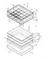
バックライト装置3は、図1に示すように発光部16に対して、光拡散板17と、拡散シート18と、プリズムシート19と、偏光変換シート20等の光学シート群21が積層状態に組み合わされて構成され、全体を図示しない遮光筐体内に収納する。バックライト装置3は、発光部16から出射された照明光が光学シート群21を通過することにより所定の光学特性を有してより均一な状態とされてカラー液晶表示パネル2に供給する。光学シート群21は、光拡散板17が発光部16から出射された照明光を内部拡散させることで、面発光における輝度の均一化を行う。光学シート群21は、光拡散板17から出射された照明光をこの拡散板17の法線方向に立ち上げることで、面発光における輝度を上昇させる働きをする。 As shown in FIG. 1, the
ここで、バックライト装置3の発光部16の基本的な構成について、図3を参照して説明する。発光部16は、実装基板15の主面15Aを詳細を後述する遮光隔壁部(体)22により4×4のマトリクス状に配列され互いに光学的に遮光された領域に分割して、単位発光モジュール23A〜23P(以下、個別に説明する場合を除いて単位発光モジュール23と総称する。)を構成する。発光部16は、各単位発光モジュール23内に、光源としてそれぞれ複数個の赤色光を発光する赤色発光ダイオード14Rと、緑色光を発光する緑色発光ダイオード14Gと、青色光を発光する青色発光ダイオード14Bが実装基板15に互いに直列に接続されて実装される。発光部16は、各単位発光モジュール23内においてそれぞれ赤色発光ダイオード14Rと緑色発光ダイオード14Gと青色発光ダイオード14Bが1:2:1の割合、実施の形態においてはそれぞれ4個、8個、4個が備えられる。 Here, a basic configuration of the
発光部16は、1枚の実装基板15を各単位発光モジュール23に分割するようにしたが、かかる構成に限定されるものでは無い。発光部16は、実装基板15が各単位発光モジュール23に対応した16枚の基板によって構成してもよく、また縦列或いは横列の単位発光モジュール23に対応した4枚の基板によって構成してもよい。 The
発光部16は、図示を省略するが実装基板15の主面15Aに各単位発光モジュール23に対応して各発光ダイオード14を実装して電気的に接続する配線パターンが形成される。実装基板15は、各配線パターンを各単位発光モジュール23を仕切る遮光隔壁部22の形成領域へと延長し、この領域においてそれぞれコネクタ24A〜24P(以下、個別に説明する場合を除いてコネクタ24と総称する。)を搭載する。実装基板15は、後述するようにこれらコネクタ24を介して各配線パターンが遮光隔壁部22内に設けられる回路基板25と電気的に接続される。 Although not shown, the
発光部16は、図3に示すように遮光隔壁部22が、詳細を後述するが実装基板15に対してその主面15A上に直交状態で組み付けられる回路基板25と、この回路基板25を被覆する遮光シート体26とにより構成する。発光部16は、回路基板25に、各単位発光モジュール23の各発光ダイオード14に駆動電源を供給する電源パターンや、各単位発光モジュール23に対応して各発光ダイオード14の駆動回路素子或いは各駆動回路素子に対して駆動制御信号を供給する信号パターンが形成される。発光部16は、回路基板25に、各単位発光モジュール23に対応して、それぞれから出射される照明光を検出する光量センサ27が搭載される。発光部16は、具体的には赤色出射光成分の光量を検出する赤色光センサ27Rと、緑色出射光成分の光量を検出する緑色光センサ27Gと、青色出射光成分の光量を検出する青色光センサ27Bとを搭載する。 As shown in FIG. 3, the light-emitting
発光部16は、図3に示すように遮光シート体26の側面に各単位発光モジュール23に開口するセンサ孔28が設けられており、このセンサ孔28を介してセンサ27のセンサ部が相対する単位発光モジュール23に臨ませられる。なお、発光部16は、各単位発光モジュール23に対して1個のセンサ27を設ける必要は無く、適当な間隔を以って単位発光モジュール23照明光を検出するようにしてもよい。発光部16は、この場合にセンサ孔28が検出対象の単位発光モジュール23に対応して遮光シート体26に設けられる。 As shown in FIG. 3, the
遮光シート体26は、単位発光モジュール23から出射される照明光の漏れを防止すればよく、例えば拡散フィルムとして一般的に用いられるポリエステルシート等を基材として反射樹脂をコーティングした遮光性とともに電気的絶縁性を有し反射特性の向上を図ったシート体が好適に用いられる。遮光シート体26については、回路基板25により充分な遮光作用が奏される場合には不要としてもよい。 The light-shielding
発光部16は、実装基板15に蛍光管よりも発熱量の大きな多数個の発光ダイオード14を搭載する。発光部16は、各発光ダイオード14から発生した熱が遮光筐体内に籠もることにより高温となって各発光ダイオード14の発光特性を低下させたり回路素子等の動作を不安定とさせる虞を防止するために、実装基板15の底面15B側に詳細を後述する放熱構造29が設けられて効率的な放熱が行われるように構成される。 In the
以上のように構成されるカラー画像表示装置1は、例えば図4に示す駆動回路30により駆動される。駆動回路30は、カラー液晶表示パネル2やバックライト装置3に駆動電源を供給する電源部31と、外部から供給される映像信号や当該カラー画像表示装置1が備える図示しない受信部で受信された映像信号が入力端子32を介して供給されるビデオデコーダ33を備える。駆動回路30は、ビデオデコーダ33に接続された制御信号作成部34と、この制御信号作成部34に接続され各単位発光モジュール23毎に設けられるバックライト駆動制御部35及びビデオエンコーダ36と、このビデオエンコーダ36の出力に応じてカラー液晶表示パネル2を駆動するXドライバ回路37及びYドライバ回路38等を備える。 The color
駆動回路30においては、入力端子32を介して入力された映像信号が、ビデオデコーダ33によりクロマ処理などの信号処理がなされ、さらにコンポジット信号からカラー液晶表示パネル2の駆動に適したそれぞれmビット(mは8〜12を想定)のRGBデータに変換されて、水平同期信号H及び垂直同期信号Vとともに制御信号作成部34に供給される。駆動回路30においては、制御信号作成部34においてビデオデコーダ33から供給されるRGBデータに基づいて映像信号データを作成し、水平同期信号H及び垂直同期信号Vとともにビデオエンコーダ36に供給する。 In the
また、駆動回路30においては、映像信号データに基づいて制御信号作成部34からバックライト駆動制御部35に対して、バックライト装置3の各単位発光モジュール23の発光ダイオード14を映像信号の明るさに応じて個別に駆動制御する光量制御信号を供給する。駆動回路30においては、バックライト駆動制御部35に、各単位発光モジュール23に対応して設けた光量センサ27から照明光の光量を個別に順次検出した光量検出信号が供給されている。 In the
バックライト駆動制御部35は、制御信号作成部34から供給される映像信号の明るさに応じた光量制御信号に基づいて各単位発光モジュール23の発光量を個別に制御することにより、各単位発光モジュール23の明るさを個別に制御するとともに光量センサ27により検出される光量検出信号に基づいて、各発光ダイオード14に流す駆動電流の大きさを制御する。駆動回路30においては、これにより各単位発光モジュール23における各色発光ダイオード14R、14G、14Bの明るさが制御され、各単位発光モジュール23から出射される照明光の各色の光量バランスを個別に制御する。 The backlight
バックライト駆動制御部35は、具体的には例えば図5に示す構成により各単位発光モジュール23に設けられた各色発光ダイオード14R、14G、14Bを制御する。バックライト駆動制御部35は、単位発光モジュール23に対応して設けた各色光量センサ27R、27G、27Bから各色の光量検出信号が供給される光量バランス制御部39と、緑色光センサ27Gから緑色の光量検出信号が供給される光量制御部40を備える。バックライト駆動制御部35は、光量バランス制御部39と各色発光ダイオード14R、14G、14Bに相対して接続される定電流ドライバ41R、41G、41Bと、光量制御部40に接続されたPWMドライバ42と、このPWMドライバ42により制御されるPWMスイッチ回路43等を備える。 Specifically, the backlight
バックライト駆動制御部35は、PWMスイッチ回路43が、各単位発光モジュール23内でそれぞれ直列に接続されて設けられた各発光ダイオード14R、14G、14BをそれぞれPWM駆動するためのPWMスイッチ44R、44G、44Bからなる。バックライト駆動制御部35は、定電流ドライバ41Rと、単位発光モジュール23内で直列接続された4個の赤色発光ダイオード14Rと、PWMスイッチ44Rとが直列に接続される。バックライト駆動制御部35は、定電流ドライバ41Gと、単位発光モジュール23内で直列接続された8個の緑色発光ダイオード14Gと、PWMスイッチ44Gとが直列に接続される。バックライト駆動制御部35は、定電流ドライバ41Bと、単位発光モジュール23内で直列接続された4個の青色発光ダイオード14Bと、PWMスイッチ44Bとが直列に接続される。 The backlight
バックライト駆動制御部35においては、光量バランス制御部37が、赤色光量センサ27R、緑色光量センサ27G及び青色光量センサ27Bにより検出した各色の光量検出信号に基づいて、例えば緑色の光量と赤色及び青色の光量を一致させる光量バランス制御信号を生成する。バックライト駆動制御部35においては、この光量バランス制御信号により各定電流ドライバ41R、41G、41Bをそれぞれ制御することにより、各色の発光ダイオード14R、14G、14Bに供給する駆動電流を制御する。バックライト駆動制御部35は、これにより各単位発光モジュール23から出射される照明光の光量バランスを制御する。 In the backlight
また、バックライト駆動制御部35においては、光量制御部40が、緑色光量センサ27Gによる緑色成分の光量検出信号に基づいて各単位発光モジュール23から出射される照明光の全体の発光量を示す光量制御信号を生成し、PWMドライバ42に供給する。バックライト駆動制御部35においては、PWMドライバ42に制御信号作成部34により作成された光量制御信号が供給されており、光量制御部40から供給される光量制御信号と制御信号作成部34から供給される光量制御信号に基づいてPWMドライバ42からの駆動制御信号によりカラー液晶表示パネル2を駆動する。PWMドライバ42は、表示される映像に対応する単位発光モジュール23に必要とされる明るさを確保するデューティ比のPWM制御信号を生成し、このPWM制御信号によりPWMスイッチ回路43の各PWMスイッチ44R、44G、44Bがそれぞれ制御されるようにする。バックライト駆動制御部35においては、これによりカラー液晶表示パネル2を駆動して表示される映像に対応して単位発光モジュール23から出射される照明光が所定の明るさに確保されるように、各発光ダイオード14R、14G、14BがPWM制御されるようにする。 In the backlight
バックライト駆動制御部35は、各単位発光モジュール23毎にそれぞれ対応して設けられるが、上述した構成各部が詳細を後述する各単位発光モジュール23を構成する遮光隔壁部22に収納される回路基板25に搭載される。バックライト駆動制御部35は、例えば図5において鎖線で囲んだ光量バランス制御部39と、光量制御部40と、定電流ドライバ41と、PWMドライバ42及びPWMスイッチ回路43が駆動制御素子45として1チップ化されて各単位発光モジュール23に対応して回路基板25に搭載される。バックライト駆動制御部35は、上述したように光量センサ27が、駆動制御素子45とともに回路基板25に搭載される。 The backlight
カラー画像表示装置1は、上述したようにカラー液晶表示パネル2と、このカラー液晶表示パネル2に対して背面側から照明光を供給するバックライト装置3とを備える透過型のカラー液晶表示装置であり、バックライト装置3がそれぞれ所定個数の発光ダイオード14R、14G、14Bを有して互いに光学的に仕切られた多数の単位発光モジュール23を構成するとともに、各単位発光モジュール23がそれぞれ独立して発光ダイオード14R、14G、14Bの発光制御が行われる分割型バックライト方式を採用する。カラー画像表示装置1は、各単位発光モジュール23に設けた光量センサ27により出射する照明光の各色成分の光量を検出して各発光ダイオード14R、14G、14Bの発光制御を行う。したがって、カラー画像表示装置1は、バックライト装置3からの照明光が映像信号に基づいて部分的に変調して供給され、光量バランスのずれによる表示画像の色むらの発生を防止してカラー液晶表示パネル2における変調制御を補完して原画像をより精度よく再現する良好な画像が得られるようになる。 As described above, the color
なお、バックライト装置3においては、各単位発光モジュール23に対応して光量センサ27を配置して出射する照明光の各色成分の光量検出を行うようにしたが、かかる構成に限定されるものでは無い。バックライト装置3は、例えば各発光ダイオード14R、14G、14Bが一定の領域においてほぼ同等の発光特性を有するものが選択されて配置されることにより光量バランスが比較的安定している場合等において、所定の単位発光モジュール23を対象として光量センサ27を設けて複数の単位発光モジュール23について一括して光量バランスの制御を行うようにしてもよい。 In the
上述したカラー画像表示装置1に備えられるバックライト装置3の発光部16の構成について、図6及び図7を参照してさらに詳細に説明する。発光部16は、上述したように領域内に所定個数の赤色発光ダイオード14Rと緑色発光ダイオード14Gと青色発光ダイオード14Bを配列するように実装基板15の主面15Aを遮光隔壁部22により光学的遮光領域に分割して単位発光モジュール23を構成する。発光部16は、遮光隔壁部22内に各単位発光モジュール23に対応して回路基板25が収納され、この回路基板25に単位発光モジュール23の各発光ダイオード14を駆動する駆動回路30を1チップ化した駆動制御素子45が搭載される。回路基板25には、駆動制御素子45とともに光量センサ27も搭載される。 The configuration of the
発光部16は、回路基板25が、各単位発光モジュール23を構成するように実装基板15の主面15A上に直交状態で搭載されればよく、図6に様々な態様で図示している。すなわち、第1態様の回路基板25は、各単位発光モジュール23の長手方向の境界線上に沿って実装基板15に並べられて実装されたコネクタ24にそれぞれ差し込まれて組み付けられる16枚の回路基板46A〜46Pによって構成する。各回路基板46には、相対する単位発光モジュール23に対応してそれぞれ駆動制御素子45と光量センサ27が搭載される。回路基板46は、例えば実装基板15の一方側にそれぞれ実装される4枚の回路基板46A(46E、46I、46M)が入出力基板を構成し、それぞれ側方へと延長されて入出力コネクタ47が設けられる。 The
また、第2態様の回路基板25は、例えば横方向に並ぶ各単位発光モジュール23に共通して長手方向の境界線上に沿って実装基板15上に組み付けられる4枚の共通回路基板48A〜48Dによって構成する。各共通回路基板48は、上述したように各単位発光モジュール23に対応して個別の駆動制御素子45を搭載してもよいが、図に示すように横方向に並んだ各単位発光モジュール23を個別に制御することが可能な1チップ化された大型の駆動制御素子49を搭載するようにしてもよい。また、各共通回路基板48は、光量検出を共通化する場合に、所定の単位発光モジュール23に対応して光量センサ27を搭載する。回路基板25にも、実装基板15の一方側において側方へと延長された端部に入出力コネクタ47が設けられる。各共通回路基板48も、各単位発光モジュール23の長手方向の境界線上に沿って実装基板15に並べられて実装されたコネクタ24にそれぞれ差し込まれて組み付けられる。 Further, the
発光部16は、図6に示すように、例えば実装基板15をアルミプレート等の熱伝導率が良好な金属プレートからなる支持基板50上に組み付けるとともに支持基板50の底面側に複数のヒートパイプ51を敷設し、これら支持基板50とヒートパイプ51とにより実装基板15の底面15B側に放熱構造29を構成する。発光部16は、上述したように発光ダイオード14を駆動するための電源ラインや信号ライン或いはバックライト駆動制御部35を全て実装基板15の主面15A側に設けることから、大型の放熱構造29を実装基板15の底面15B側に直接設けることが可能である。 As shown in FIG. 6, the
発光部16においては、例えば実装基板15に図示しない多数個の放熱用スルーホールが形成され、これら放熱用スルーホールを介して実装基板15と支持基板49との間で熱伝導が行われるように構成する。発光部16は、支持基板50の延長端や各ヒートパイプ51を図示しないヒートシンク等の放熱部材と接続して効率的な放熱が行われるようにする。したがって、発光部16は、各発光ダイオード14からの発生熱が実装基板15から放熱用スルーホールを介して支持基板49側へと伝導され、支持基板49と各ヒートパイプ51とによる効率的な放熱が行われる。発光部16は、これにより各発光ダイオード14から発生する大量の熱が効率よく放熱されるようになり、各発光ダイオード14や各種の電子部品等が安定した動作が行われる。なお、発光部16は、かかる放熱構造29に限定されるものでは無いことは勿論であり、従来の電子機器等に採用されている放熱構造を設けることが可能である。 In the
発光部16は、上述したように各単位発光モジュール23を仕切るようにして実装基板15の主面15A上に回路基板25が直交状態で搭載される。発光部16においては、各回路基板25を被覆しかつ回路基板25が存在しない各単位発光モジュール23の縦方向の境界線に沿った遮光隔壁部22を遮光シート体26によって構成する。遮光シート体26は、上述したようにポリエステルシート等を基材として反射樹脂をコーティングした遮光性とともに電気的絶縁性を有し反射特性の向上を図ったシート体により形成される。 As described above, in the
遮光シート体26は、例えば図6に示すように5個の横枠壁52A〜52Eと縦枠壁53A〜53Eを枠組みして内部に各単位発光モジュール23を仕切るマトリックス状に配列された空間部54A〜54Pを構成した一体型部材として形成される。遮光シート体26は、図7に示すように少なくとも各横枠壁52が内部に下方部を開放されるとともに回路基板25を収納することが可能な間隙を有するチャンネル状に形成される。遮光シート体26には、外周部位を構成する横枠壁52A、52Eと縦枠壁53A、53Eの外側面に、実装基板15に取り付けるための舌片状の取付片55が一体に形成されている。 For example, as shown in FIG. 6, the light-shielding
以上のように構成された遮光シート体26は、図6に矢印で示すように、多数個の発光ダイオード14を実装するとともに回路基板25を組み付けた実装基板15に対して組み合わされる。遮光シート体26は、各横枠壁52の内部にそれぞれ回路基板25を収納するようにして組み合わされた後に各取付片55を介して実装基板15の主面15A上に固定される。遮光シート体26は、これにより図3に示すように各空間部54内にそれぞれ所定個数の赤色発光ダイオード14Rと緑色発光ダイオード14Gと青色発光ダイオード14Bとを配列し、それぞれが横枠壁52と縦枠壁53とにより光学的に分離された単位発光モジュール23を仕切る遮光隔壁部22を実装基板15上に構成する。 The light
図8に示した発光部60は、各単位発光モジュール23が独立の実装基板61A〜61Pを備えるとともに、横枠壁を構成するチャンネル状の横枠遮光シート体62A〜62E(62C、62Eは図示せず)と、両側の縦枠壁を構成する縦枠遮光シート体63A、63Bと、各横枠遮光シート体62間において仕切壁を構成する仕切遮光シート体64A〜64L(一部のみ図示)とを備えた構成に特徴がある。発光部60は、その他の基本的な構成を上述した発光部16と同様とすることから、対応する部位に同一符号を付すことにより説明を省略する。 In the
発光部60は、各実装基板61が支持基板50上に位置決めされて取り付けられ、これ実装基板61に対してそれぞれ回路基板46が組み付けられる。発光部60は、この状態で各横方向に並んだ回路基板46を一括して被覆するようにして横枠遮光シート体62が組み合わされる。発光部60は、各横枠遮光シート体62の両端部を閉塞するようにして縦枠遮光シート体63A、63Bが組み合わされるとともに、各単位発光モジュール23の境界線上において各仕切遮光シート体64が両端を各横枠遮光シート体62の側面に固定されて組み合わされることにより、遮光隔壁部22が実装基板15上に構成される。 The
発光部16には、例えば図9に示した多数個の独立型実装基板70を用いるようにしてもよい。実装基板70は、上述した所定個数の発光ダイオード14を実装する実装基板15に対応する発光ダイオード実装部71と、バックライト駆動制御部35を搭載した回路基板25に対応する駆動回路実装部72とが連結部73を介して一体に形成された構造に特徴を有している。実装基板70は、連結部73に発光ダイオード実装部71側に設けた回路パターンと駆動回路実装部72側に設けた回路パターンとを接続する電源パターンや信号パターンが形成される。実装基板70は、連結部73が、例えば薄肉とされて発光ダイオード実装部71に対して駆動回路実装部72を折曲自在とする。なお、実装基板70は、例えば発光ダイオード実装部71と駆動回路実装部72をいわゆるリジット基板により形成するとともに可撓性を有するフレキシブル基板からなる連結部73によって連結した複合基板により構成してもよい。 For the
以上のように構成された実装基板70は、発光ダイオード実装部71を支持基板50に取り付けた状態で、図9(B)に示すように連結部73を介して駆動回路実装部72が直交状態に折り曲げられる。実装基板70は、この状態で駆動回路実装部72を被覆して遮光シート体26が組み合わされることにより、遮光隔壁部22が構成されるようになる。なお、実装基板70は、同図(A)に示すように連結部73が発光ダイオード実装部71と駆動回路実装部72に対して幅狭とされるが、例えば駆動回路実装部72と同幅として折曲することにより直接単位発光モジュール23の隔壁を構成するようにしてもよい。単位発光モジュール23は、この構成により実装基板70の駆動回路実装部72と連結部73とにより光漏れを防止する隔壁が構成される。 In the mounting
図10に示した発光部80は、端部が突き合わされて支持基板50上に取り付けられることにより隣り合う単位発光モジュール81A、81Bを構成する実装基板82A、82B間に共通の接続回路基板83を組み付けることにより、遮光隔壁部を構成した構成に特徴を有している。接続回路基板83は、第1の実装基板82A側に実装したコネクタ24Aに結合される第1回路基板部84Aと、第2の実装基板82B側に実装したコネクタ24Bに結合される第2回路基板部84Bが中間部85に対してそれぞれ第1ヒンジ部86Aと第2ヒンジ部86Bとを介して連結されることにより一体に形成される。 The
接続回路基板83には、第1回路基板部84A側に単位発光モジュール81Aを駆動する駆動制御素子45Aを搭載するとともに、詳細を省略する第1の実装基板82Aと接続する電源パターンや信号パターンが形成される。接続回路基板83には、第2回路基板部84B側に単位発光モジュール81Bを駆動する駆動制御素子45Bを搭載するとともに、詳細を省略する第2の実装基板82Bと接続する電源パターンや信号パターンが形成される。なお、接続回路基板83は、中間部85に第1の実装基板82Aと第2回路基板部84Bとに共通する駆動制御素子45を搭載するようにしてもよいことは勿論である。接続回路基板83は、これにより単位発光モジュール81Aや単位発光モジュール81Bに臨む側面を平坦面として照明光が良好な状態で出射されるようにする。 On the connection circuit board 83, a
発光部80においては、接続回路基板83が、第1ヒンジ部86Aと第2ヒンジ部86Bとをそれぞれ山折りすることにより図10に示すように全体をチャンネル状とした状態で、第1回路基板部84Aの先端側に形成したコネクタ部をコネクタ24Aに差し込んで結合するとともに、第2回路基板部84Bの先端側に形成したコネクタ部をコネクタ24Bにに差し込んで結合する。発光部80においては、接続回路基板83が、第1の実装基板82Aと第2の実装基板82Bとの間に高さ方向に介在し、隣り合う単位発光モジュール81A、81B間を光学的に分離する。 In the
なお、本発明は、上述した各実施の形態に限定されるものでは無いことは勿論である。各実施の形態においては、実装基板15に対して横方向に並ぶ各単位発光モジュール23に沿って回路基板25を配置した構造を示したが、回路基板25が各単位発光モジュール23の縦方向に沿って配置されるようにしてもよい。また、回路基板25は、例えば信号系と電源系のパターンを区分するために、横方向と縦方向に分けて実装基板15に対して配置するようにしてもよい。さらに、遮光隔壁部22については、各単位発光モジュール23の回路基板25が配置されない部位において、例えば絶縁材を印刷法等によりある程度の高さに盛り上げて隔壁を構成するようにしてもよい。 Needless to say, the present invention is not limited to the above-described embodiments. In each embodiment, the
1 カラー画像表示装置、2 透過型カラー液晶表示パネル、3 バックライト装置、14 発光ダイオード、14R 発光ダイオード、14G 緑色発光ダイオード、14B 青色発光ダイオード、15 実装基板、16 発光部、21 光学シート群、22 遮光隔壁部、23 単位発光モジュール、24 コネクタ、25 回路基板、26 遮光シート体、27 光量センサ、28 センサ孔、29 放熱構造、30 駆動回路、31 電源部、34 制御信号作成部、35 バックライト駆動制御部、39 光量バランス制御部、40 光量制御部、41 定電流ドライバ、42 PWMスイッチ回路、45 駆動制御素子、46 回路基板、47 入出力コネクタ、48 共通回路基板、49 駆動制御素子、50 支持基板、51 ヒートパイプ、52 横枠壁、53 縦枠壁、54 空間部、55 取付片、60 発光部、61 実装基板、62 横枠遮光シート体、63 縦枠遮光シート体、64 仕切遮光シート体、70 実装基板、71 発光ダイオード実装部、72 駆動回路実装部、72 連結部、80 発光部、81 単位発光モジュール、82 実装基板、83 接続基板 DESCRIPTION OF SYMBOLS 1 Color image display apparatus, 2 transmissive | pervious color liquid crystal display panel, 3 backlight apparatus, 14 light emitting diode, 14R light emitting diode, 14G green light emitting diode, 14B blue light emitting diode, 15 mounting board | substrate, 16 light emission part, 21 optical sheet group, 22 light shielding partition part, 23 unit light emitting module, 24 connector, 25 circuit board, 26 light shielding sheet body, 27 light quantity sensor, 28 sensor hole, 29 heat radiation structure, 30 drive circuit, 31 power supply part, 34 control signal creation part, 35 back Light drive control unit, 39 Light quantity balance control unit, 40 Light quantity control unit, 41 Constant current driver, 42 PWM switch circuit, 45 Drive control element, 46 Circuit board, 47 Input / output connector, 48 Common circuit board, 49 Drive control element, 50 support substrate, 51 heat pipe, 52 Horizontal frame wall, 53 Vertical frame wall, 54 Space portion, 55 Mounting piece, 60 Light emitting portion, 61 Mounting substrate, 62 Horizontal frame light shielding sheet body, 63 Vertical frame light shielding sheet body, 64 Partition light shielding sheet body, 70 Mounting substrate, 71 Light emitting diode mounting part, 72 Drive circuit mounting part, 72 connecting part, 80 light emitting part, 81 unit light emitting module, 82 mounting board, 83 connection board
Claims (8)
Translated fromJapanese上記各単位発光モジュールが、上記各単色光源の実装面と直交して立設された遮光隔壁体によりそれぞれ仕切られるとともに、上記遮光隔壁体に上記各単色光源を配置した上記各単位発光モジュール間を電気的に接続する配線手段が設けられることを特徴とするバックライト装置。A plurality of light sources mounted on the same surface are a plurality of types of single color light sources that emit light having different wavelengths, and a unit light emitting module is configured by combining a predetermined number of each single color light source. Is a backlight device in which light emission control is performed independently for each of the unit light emitting modules, while emitting mixed color light, which is a mixture of the emitted light from each of the monochromatic light sources, as illumination light,
Each unit light emitting module is partitioned by a light shielding partition that is erected perpendicularly to the mounting surface of each single color light source, and between each unit light emitting module in which each single color light source is disposed on the light shielding partition. A backlight device comprising wiring means for electrical connection.
上記遮光シート体に、上記センサを相対する上記単位発光モジュールの内部に臨ませるセンサ孔が設けられることを特徴とする請求項1記載のバックライト装置。The light-shielding partition body is a drive circuit for driving the monochromatic light sources arranged in the unit light emitting modules or a power supply circuit for supplying power, and a sensor for detecting the state of mixed light emitted from the unit light emitting modules. And a circuit board that constitutes the wiring means by being provided with a sensor circuit, and a light-shielding sheet body that has a light-shielding characteristic provided to cover the circuit board,
The backlight device according to claim 1, wherein a sensor hole is provided in the light-shielding sheet body so that the sensor faces the inside of the unit light emitting module facing the sensor.
上記バックライト装置が、同一面上に実装した多数個の光源が、波長を異にする出射光を出射する複数種の単色光源であるとともに所定個数の各単色光源を組み合わせて単位発光モジュールを構成し、これら単位発光モジュールがそれぞれの上記各単色光源からの出射光を混色した混色光を照明光として上記カラー表示パネルに供給するとともに上記各単位発光モジュール毎に発光制御が独立して行われ、
上記各単位発光モジュールが、上記各単色光源の実装面と直交して立設された遮光隔壁体によりそれぞれ仕切られるとともに、上記遮光隔壁体に上記各単色光源を配置した上記各単位発光モジュール間を電気的に接続する配線手段が設けられることを特徴とするカラー画像表示装置。In a color image display device comprising a color display panel and a backlight device for supplying illumination light from the back side of the color display panel,
In the backlight device, a plurality of light sources mounted on the same surface are a plurality of types of monochromatic light sources that emit emitted light having different wavelengths, and a unit light emitting module is configured by combining a predetermined number of each monochromatic light source Then, these unit light emitting modules supply mixed color light, which is a mixture of light emitted from the respective single color light sources, to the color display panel as illumination light, and light emission control is performed independently for each unit light emitting module,
Each unit light emitting module is partitioned by a light shielding partition that is erected perpendicularly to the mounting surface of each single color light source, and each unit light emitting module in which each single color light source is disposed on the light shielding partition. A color image display device comprising wiring means for electrical connection.
Priority Applications (1)
| Application Number | Priority Date | Filing Date | Title |
|---|---|---|---|
| JP2006150416AJP4605096B2 (en) | 2006-05-30 | 2006-05-30 | Backlight device and color image display device |
Applications Claiming Priority (1)
| Application Number | Priority Date | Filing Date | Title |
|---|---|---|---|
| JP2006150416AJP4605096B2 (en) | 2006-05-30 | 2006-05-30 | Backlight device and color image display device |
Publications (2)
| Publication Number | Publication Date |
|---|---|
| JP2007323857A JP2007323857A (en) | 2007-12-13 |
| JP4605096B2true JP4605096B2 (en) | 2011-01-05 |
Family
ID=38856495
Family Applications (1)
| Application Number | Title | Priority Date | Filing Date |
|---|---|---|---|
| JP2006150416AExpired - Fee RelatedJP4605096B2 (en) | 2006-05-30 | 2006-05-30 | Backlight device and color image display device |
Country Status (1)
| Country | Link |
|---|---|
| JP (1) | JP4605096B2 (en) |
Cited By (1)
| Publication number | Priority date | Publication date | Assignee | Title |
|---|---|---|---|---|
| CN101965477A (en)* | 2008-03-07 | 2011-02-02 | 三美电机株式会社 | Liquid crystal backlight device |
Families Citing this family (32)
| Publication number | Priority date | Publication date | Assignee | Title |
|---|---|---|---|---|
| WO2009093363A1 (en)* | 2008-01-22 | 2009-07-30 | Sharp Kabushiki Kaisha | Illuminating device, display device and television receiver |
| EP2306070A4 (en)* | 2008-07-29 | 2013-07-03 | Sharp Kk | LIGHTING APPARATUS, DISPLAY APPARATUS AND TELEVISION RECEIVER |
| KR101502420B1 (en) | 2008-09-22 | 2015-03-25 | 삼성디스플레이 주식회사 | Light source module and display device having the same |
| US9081227B2 (en) | 2010-07-13 | 2015-07-14 | Sharp Kabushiki Kaisha | Lighting device having reflecting sheet and connector for fastening said reflecting sheet and display device |
| US8564000B2 (en) | 2010-11-22 | 2013-10-22 | Cree, Inc. | Light emitting devices for light emitting diodes (LEDs) |
| US9490235B2 (en) | 2010-11-22 | 2016-11-08 | Cree, Inc. | Light emitting devices, systems, and methods |
| US9300062B2 (en) | 2010-11-22 | 2016-03-29 | Cree, Inc. | Attachment devices and methods for light emitting devices |
| US8575639B2 (en) | 2011-02-16 | 2013-11-05 | Cree, Inc. | Light emitting devices for light emitting diodes (LEDs) |
| US8624271B2 (en) | 2010-11-22 | 2014-01-07 | Cree, Inc. | Light emitting devices |
| US9000470B2 (en) | 2010-11-22 | 2015-04-07 | Cree, Inc. | Light emitter devices |
| JP2015038808A (en)* | 2010-12-01 | 2015-02-26 | シャープ株式会社 | Surface light-emitting lighting device |
| CN102537710A (en)* | 2010-12-31 | 2012-07-04 | 亿广科技(上海)有限公司 | Lighting fixture and shading device for same |
| US8455908B2 (en) | 2011-02-16 | 2013-06-04 | Cree, Inc. | Light emitting devices |
| USD702653S1 (en) | 2011-10-26 | 2014-04-15 | Cree, Inc. | Light emitting device component |
| US8809880B2 (en) | 2011-02-16 | 2014-08-19 | Cree, Inc. | Light emitting diode (LED) chips and devices for providing failure mitigation in LED arrays |
| JP5939930B2 (en)* | 2011-09-21 | 2016-06-22 | キヤノン株式会社 | Light source device |
| KR20140097284A (en) | 2011-11-07 | 2014-08-06 | 크리,인코포레이티드 | High voltage array light emitting diode(led) devices, fixtures and methods |
| JP5192071B2 (en)* | 2011-11-09 | 2013-05-08 | シャープ株式会社 | Surface emitting lighting device |
| US10043960B2 (en) | 2011-11-15 | 2018-08-07 | Cree, Inc. | Light emitting diode (LED) packages and related methods |
| US9735198B2 (en) | 2012-03-30 | 2017-08-15 | Cree, Inc. | Substrate based light emitter devices, components, and related methods |
| US10134961B2 (en) | 2012-03-30 | 2018-11-20 | Cree, Inc. | Submount based surface mount device (SMD) light emitter components and methods |
| CN102901014A (en)* | 2012-11-14 | 2013-01-30 | 深圳市华星光电技术有限公司 | Direct type backlight module and liquid crystal display module using same |
| US9345091B2 (en) | 2013-02-08 | 2016-05-17 | Cree, Inc. | Light emitting device (LED) light fixture control systems and related methods |
| USD739565S1 (en) | 2013-06-27 | 2015-09-22 | Cree, Inc. | Light emitter unit |
| USD740453S1 (en) | 2013-06-27 | 2015-10-06 | Cree, Inc. | Light emitter unit |
| JP6141347B2 (en)* | 2014-06-05 | 2017-06-07 | キヤノン株式会社 | Light source device and display device |
| USD823492S1 (en) | 2016-10-04 | 2018-07-17 | Cree, Inc. | Light emitting device |
| CN110234397B (en)* | 2017-01-26 | 2021-11-09 | 夏普株式会社 | Light therapeutic equipment |
| US11079096B2 (en) | 2018-05-31 | 2021-08-03 | Nichia Corporation | Lighting fixture and lighting apparatus |
| JP2020205183A (en)* | 2019-06-18 | 2020-12-24 | 株式会社ジャパンディスプレイ | Electronic apparatus and display device |
| CN112992882B (en)* | 2019-12-18 | 2025-05-09 | 隆达电子股份有限公司 | Light emitting module and display device |
| WO2024021074A1 (en)* | 2022-07-29 | 2024-02-01 | 京东方科技集团股份有限公司 | Light-emitting substrate, backlight module, display apparatus, and preparation method for light-emitting substrate |
Family Cites Families (5)
| Publication number | Priority date | Publication date | Assignee | Title |
|---|---|---|---|---|
| JP3633125B2 (en)* | 1996-07-24 | 2005-03-30 | 株式会社シチズン電子 | Color display device |
| JP4050802B2 (en)* | 1996-08-02 | 2008-02-20 | シチズン電子株式会社 | Color display device |
| JP4355977B2 (en)* | 1999-11-12 | 2009-11-04 | ソニー株式会社 | Image display device and illumination control method in image display device |
| JP4147843B2 (en)* | 2002-07-05 | 2008-09-10 | セイコーエプソン株式会社 | Backlight device |
| JP4403389B2 (en)* | 2004-06-11 | 2010-01-27 | ソニー株式会社 | Backlight device |
- 2006
- 2006-05-30JPJP2006150416Apatent/JP4605096B2/ennot_activeExpired - Fee Related
Cited By (2)
| Publication number | Priority date | Publication date | Assignee | Title |
|---|---|---|---|---|
| CN101965477A (en)* | 2008-03-07 | 2011-02-02 | 三美电机株式会社 | Liquid crystal backlight device |
| CN101965477B (en)* | 2008-03-07 | 2013-04-03 | 三美电机株式会社 | Liquid crystal backlight device |
Also Published As
| Publication number | Publication date |
|---|---|
| JP2007323857A (en) | 2007-12-13 |
Similar Documents
| Publication | Publication Date | Title |
|---|---|---|
| JP4605096B2 (en) | Backlight device and color image display device | |
| JP4977206B2 (en) | LIGHTING DEVICE AND DISPLAY DEVICE USING THE SAME | |
| KR101308752B1 (en) | Liquid crystal display device | |
| KR101280390B1 (en) | Light emitting diode backlight unit and liquid crystal display device module using the same | |
| KR101442006B1 (en) | Backlight assembly and display device having same | |
| JP4666387B2 (en) | Backlight unit and image display device including the unit | |
| WO2006040937A1 (en) | Light source unit for backlight, backlight device for liquid crystal display, and transmissive liquid crystal display device | |
| JP4977207B2 (en) | LIGHTING DEVICE AND DISPLAY DEVICE USING THE SAME | |
| JP4701806B2 (en) | Backlight device and liquid crystal display device | |
| JP4650085B2 (en) | Backlight device and liquid crystal display device | |
| US8721150B2 (en) | Backlight assembly and liquid crystal display device using the same | |
| CN103392092B (en) | Lighting device, display unit, radiovisor | |
| WO2011043094A1 (en) | Lighting device and display device | |
| US20140009695A1 (en) | Illumination device, display device, and television reception device | |
| US9476577B2 (en) | Lighting device, display device, and television reception device | |
| JP2006236701A (en) | Backlight device and liquid crystal display | |
| US9004710B2 (en) | Illumination device, display device, television receiving device | |
| WO2012090809A1 (en) | Display device and drive method for same | |
| JP2006258973A (en) | Back-light device and liquid crystal display device | |
| US20120300131A1 (en) | Display device and television receiver | |
| JP2013218922A (en) | Backlight device, display device and television receiver | |
| JP2006228575A (en) | Light emitting diode, backlight device, and liquid crystal display device | |
| CN102197330A (en) | Backlight unit, liquid crystal display device, data generating method, data generating program and recording medium | |
| JP2006310833A (en) | Light source unit, and backlight apparatus and liquid crystal display apparatus using the light source | |
| JP2010139771A (en) | Liquid crystal display device |
Legal Events
| Date | Code | Title | Description |
|---|---|---|---|
| A621 | Written request for application examination | Free format text:JAPANESE INTERMEDIATE CODE: A621 Effective date:20090311 | |
| A977 | Report on retrieval | Free format text:JAPANESE INTERMEDIATE CODE: A971007 Effective date:20100902 | |
| TRDD | Decision of grant or rejection written | ||
| A01 | Written decision to grant a patent or to grant a registration (utility model) | Free format text:JAPANESE INTERMEDIATE CODE: A01 Effective date:20100907 | |
| A01 | Written decision to grant a patent or to grant a registration (utility model) | Free format text:JAPANESE INTERMEDIATE CODE: A01 | |
| A61 | First payment of annual fees (during grant procedure) | Free format text:JAPANESE INTERMEDIATE CODE: A61 Effective date:20100920 | |
| FPAY | Renewal fee payment (event date is renewal date of database) | Free format text:PAYMENT UNTIL: 20131015 Year of fee payment:3 | |
| LAPS | Cancellation because of no payment of annual fees |