JP4604545B2 - Wireless communication system, wireless communication apparatus, and wireless communication method - Google Patents
Wireless communication system, wireless communication apparatus, and wireless communication methodDownload PDFInfo
- Publication number
- JP4604545B2 JP4604545B2JP2004140485AJP2004140485AJP4604545B2JP 4604545 B2JP4604545 B2JP 4604545B2JP 2004140485 AJP2004140485 AJP 2004140485AJP 2004140485 AJP2004140485 AJP 2004140485AJP 4604545 B2JP4604545 B2JP 4604545B2
- Authority
- JP
- Japan
- Prior art keywords
- transmission
- matrix
- communication device
- wireless communication
- weight
- Prior art date
- Legal status (The legal status is an assumption and is not a legal conclusion. Google has not performed a legal analysis and makes no representation as to the accuracy of the status listed.)
- Expired - Fee Related
Links
- 238000004891communicationMethods0.000titleclaimsdescription160
- 238000000034methodMethods0.000titleclaimsdescription49
- 230000005540biological transmissionEffects0.000claimsdescription203
- 239000011159matrix materialSubstances0.000claimsdescription178
- 238000000354decomposition reactionMethods0.000claimsdescription54
- 238000000926separation methodMethods0.000claimsdescription21
- 238000004590computer programMethods0.000description16
- 238000004364calculation methodMethods0.000description15
- 239000013598vectorSubstances0.000description14
- 238000012545processingMethods0.000description13
- 230000000875corresponding effectEffects0.000description10
- 230000006870functionEffects0.000description8
- 238000010586diagramMethods0.000description6
- 238000012546transferMethods0.000description6
- 230000008569processEffects0.000description5
- 101100172132Mus musculus Eif3a geneProteins0.000description4
- 239000000969carrierSubstances0.000description3
- 238000005516engineering processMethods0.000description3
- 230000006872improvementEffects0.000description2
- 238000012549trainingMethods0.000description2
- 230000003213activating effectEffects0.000description1
- 230000003044adaptive effectEffects0.000description1
- 230000008901benefitEffects0.000description1
- 230000002457bidirectional effectEffects0.000description1
- 230000008859changeEffects0.000description1
- 230000002079cooperative effectEffects0.000description1
- 238000012937correctionMethods0.000description1
- 230000003111delayed effectEffects0.000description1
- 230000000694effectsEffects0.000description1
- 230000014509gene expressionEffects0.000description1
- 238000003780insertionMethods0.000description1
- 230000037431insertionEffects0.000description1
- 230000007246mechanismEffects0.000description1
- 238000012986modificationMethods0.000description1
- 230000004048modificationEffects0.000description1
- 230000006855networkingEffects0.000description1
- 238000010606normalizationMethods0.000description1
- 230000002093peripheral effectEffects0.000description1
- 230000004044responseEffects0.000description1
- 238000006467substitution reactionMethods0.000description1
- 239000013589supplementSubstances0.000description1
Images


Classifications
- H—ELECTRICITY
- H04—ELECTRIC COMMUNICATION TECHNIQUE
- H04B—TRANSMISSION
- H04B7/00—Radio transmission systems, i.e. using radiation field
- H04B7/02—Diversity systems; Multi-antenna system, i.e. transmission or reception using multiple antennas
- H04B7/04—Diversity systems; Multi-antenna system, i.e. transmission or reception using multiple antennas using two or more spaced independent antennas
- H04B7/06—Diversity systems; Multi-antenna system, i.e. transmission or reception using multiple antennas using two or more spaced independent antennas at the transmitting station
- H04B7/0697—Diversity systems; Multi-antenna system, i.e. transmission or reception using multiple antennas using two or more spaced independent antennas at the transmitting station using spatial multiplexing
- H—ELECTRICITY
- H04—ELECTRIC COMMUNICATION TECHNIQUE
- H04B—TRANSMISSION
- H04B7/00—Radio transmission systems, i.e. using radiation field
- H04B7/02—Diversity systems; Multi-antenna system, i.e. transmission or reception using multiple antennas
- H04B7/04—Diversity systems; Multi-antenna system, i.e. transmission or reception using multiple antennas using two or more spaced independent antennas
- H04B7/0413—MIMO systems
- H—ELECTRICITY
- H04—ELECTRIC COMMUNICATION TECHNIQUE
- H04B—TRANSMISSION
- H04B7/00—Radio transmission systems, i.e. using radiation field
- H04B7/02—Diversity systems; Multi-antenna system, i.e. transmission or reception using multiple antennas
- H04B7/04—Diversity systems; Multi-antenna system, i.e. transmission or reception using multiple antennas using two or more spaced independent antennas
- H04B7/06—Diversity systems; Multi-antenna system, i.e. transmission or reception using multiple antennas using two or more spaced independent antennas at the transmitting station
- H04B7/0613—Diversity systems; Multi-antenna system, i.e. transmission or reception using multiple antennas using two or more spaced independent antennas at the transmitting station using simultaneous transmission
- H04B7/0615—Diversity systems; Multi-antenna system, i.e. transmission or reception using multiple antennas using two or more spaced independent antennas at the transmitting station using simultaneous transmission of weighted versions of same signal
- H—ELECTRICITY
- H04—ELECTRIC COMMUNICATION TECHNIQUE
- H04B—TRANSMISSION
- H04B7/00—Radio transmission systems, i.e. using radiation field
- H04B7/02—Diversity systems; Multi-antenna system, i.e. transmission or reception using multiple antennas
- H04B7/04—Diversity systems; Multi-antenna system, i.e. transmission or reception using multiple antennas using two or more spaced independent antennas
- H04B7/08—Diversity systems; Multi-antenna system, i.e. transmission or reception using multiple antennas using two or more spaced independent antennas at the receiving station
- H04B7/0837—Diversity systems; Multi-antenna system, i.e. transmission or reception using multiple antennas using two or more spaced independent antennas at the receiving station using pre-detection combining
- H04B7/0842—Weighted combining
- H04B7/0848—Joint weighting
Landscapes
- Engineering & Computer Science (AREA)
- Computer Networks & Wireless Communication (AREA)
- Signal Processing (AREA)
- Mobile Radio Communication Systems (AREA)
- Radio Transmission System (AREA)
Description
Translated fromJapanese本発明は、無線LAN(Local Area Network)のように複数の無線局間で広帯域の無線伝送を実現する無線通信システム、無線通信装置及び無線通信方法、並びにコンピュータ・プログラムに係り、特に、複数のアンテナを持つ送信機と複数のアンテナを持つ受信機が対となって、空間多重を利用して複数の論理的なチャネルを形成した通信(MIMO(Multi Input Multi Output)通信)を行なうことにより伝送容量の拡大する無線通信システム、無線通信装置及び無線通信方法、並びにコンピュータ・プログラムに関する。 The present invention relates to a wireless communication system, a wireless communication apparatus, a wireless communication method, and a computer program for realizing broadband wireless transmission between a plurality of wireless stations such as a wireless LAN (Local Area Network), and more particularly to a plurality of computer programs. Transmitting by performing communication (MIMO (Multi Input Multiple Output) communication) in which a transmitter having an antenna and a receiver having a plurality of antennas are paired to form a plurality of logical channels using spatial multiplexing. The present invention relates to a wireless communication system, a wireless communication apparatus, a wireless communication method, and a computer program whose capacity is increased.
さらに詳しくは、本発明は、送受信の各アンテナ対に対応するチャネルを要素としたチャネル行列の特異値分解(SVD)を利用したクローズドループ型のMIMO伝送を行なう無線通信システム、無線通信装置及び無線通信方法、並びにコンピュータ・プログラムに係り、特に、計算負荷の高いチャネル行列の特異値分解処理をより少ない回数にしてSVD−MIMO通信を実現する無線通信システム、無線通信装置及び無線通信方法、並びにコンピュータ・プログラムに関する。 More specifically, the present invention relates to a radio communication system, a radio communication apparatus, and a radio that perform closed-loop type MIMO transmission using singular value decomposition (SVD) of a channel matrix whose elements are channels corresponding to transmission / reception antenna pairs. More particularly, the present invention relates to a communication method and a computer program, and more particularly, a wireless communication system, a wireless communication apparatus, a wireless communication method, and a computer that realize SVD-MIMO communication by performing singular value decomposition processing of a channel matrix with a high calculation load fewer times・ Regarding the program.
LANを始めとするコンピュータ・ネットワーキングにより、情報資源の共有や機器資源の共有を効率的に実現することができる。ここで、旧来の有線方式によるLAN配線からユーザを解放するシステムとして、無線LANが注目されている。無線LANによれば、オフィスなどの作業空間において、有線ケーブルの大半を省略することができるので、パーソナル・コンピュータ(PC)などの通信端末を比較的容易に移動させることができる。 Information network sharing and device resource sharing can be efficiently realized by computer networking such as a LAN. Here, a wireless LAN is attracting attention as a system for releasing users from the conventional wired LAN connection. According to the wireless LAN, most of the wired cables can be omitted in a work space such as an office, so that a communication terminal such as a personal computer (PC) can be moved relatively easily.
近年では、無線LANシステムの高速化、低価格化に伴い、その需要が著しく増加してきている。特に、人の身の回りに存在する複数の電子機器間で小規模な無線ネットワークを構築して情報通信を行なうために、パーソナル・エリア・ネットワーク(PAN)の導入が検討されている。例えば、2.4GHz帯や、5GHz帯など、監督官庁の免許が不要な周波数帯域を利用して、異なった無線通信システム並びに無線通信装置が規定されている。 In recent years, the demand for wireless LAN systems has increased remarkably with the increase in speed and cost. In particular, the introduction of a personal area network (PAN) has been studied in order to construct a small-scale wireless network between a plurality of electronic devices existing around a person and perform information communication. For example, different radio communication systems and radio communication apparatuses are defined using frequency bands that do not require a license from a supervisory agency, such as 2.4 GHz band and 5 GHz band.
無線ネットワークに関する標準的な規格の1つにIEEE(The Institute of Electrical and Electronics Engineers)802.11(例えば、非特許文献1を参照のこと)や、HiperLAN/2(例えば、非特許文献2又は非特許文献3を参照のこと)やIEEE302.15.3、Bluetooth通信などを挙げることができる。IEEE802.11規格については、無線通信方式や使用する周波数帯域の違いなどにより、IEEE802.11a(例えば、非特許文献4を参照のこと),b,gといった拡張規格が存在する。 One standard for wireless networks is IEEE (The Institute of Electrical and Electronics Engineers) 802.11 (for example, see Non-Patent Document 1), HiperLAN / 2 (for example, Non-Patent
IEEE802.11aの規格では、最大で、54Mbpsの通信速度を達成する変調方式をサポートしている。しかし、通信速度として、さらなる高ビットレートを実現できる無線規格が求められている。例えば、IEEE802.11nでは、実効スループットで100MBPSを越える高速な無線LAN技術の開発を目指し、次世代の無線LAN規格を策定している。 The IEEE802.11a standard supports a modulation scheme that achieves a communication speed of 54 Mbps at the maximum. However, a wireless standard capable of realizing a higher bit rate as a communication speed is required. For example, in IEEE802.11n, the next-generation wireless LAN standard is formulated with the aim of developing a high-speed wireless LAN technology with an effective throughput exceeding 100 MBPS.
無線通信の高速化を実現する技術の1つとしてMIMO(Multi−Input Multi−Output)通信が注目を集めている。これは、送信機側と受信機側の双方において複数のアンテナ素子を備え、空間多重した伝送路(以下、「MIMOチャネル」とも呼ぶ)を実現することにより、伝送容量の拡大を図り、通信速度向上を達成する技術である。MIMO通信は、空間多重を利用するので、周波数利用効率はよい。 MIMO (Multi-Input Multi-Output) communication is attracting attention as one of the technologies for realizing high-speed wireless communication. This includes a plurality of antenna elements on both the transmitter side and the receiver side, and realizes a spatially multiplexed transmission path (hereinafter also referred to as “MIMO channel”), thereby expanding the transmission capacity and improving the communication speed. It is a technology that achieves improvement. Since MIMO communication uses spatial multiplexing, frequency utilization efficiency is good.
MIMO通信方式は、送信機において複数アンテナに送信データを分配して送出し、複数の仮想的なMIMOチャネルを利用して伝送し、受信機では複数アンテナにより受信した信号から信号処理によって受信データを得るという、チャネルの特性を利用した通信方式であり、単なる送受信アダプティブ・アレーとは相違する。 In the MIMO communication method, transmission data is distributed and transmitted to a plurality of antennas in a transmitter, transmitted using a plurality of virtual MIMO channels, and received data is processed by signal processing from signals received by the plurality of antennas in a receiver. This is a communication method that utilizes the characteristics of the channel, and is different from a simple transmission / reception adaptive array.
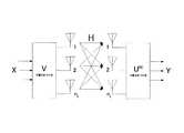
図4には、MIMO通信システムを概念的に示している。同図に示すように、送受信機各々に複数のアンテナが装備されている。送信側では、複数の送信データを空間/時間符号して多重化しM本のアンテナに分配して、複数のMIMOチャネルに送出し、受信側では、チャネル経由でN本のアンテナにより受信した受信信号を空間/時間復号して受信データを得ることができる。この場合のチャネル・モデルは、送信機周りの電波環境(伝達関数)と、チャネル空間の構造(伝達関数)と、受信機周りの電波環境(伝達関数)で構成される。各アンテナから伝送される信号を多重する際、クロストーク(Crosstalk)が発生するが、受信側の信号処理により多重化された各信号をクロストーク無しに正しく取り出すことができる。 FIG. 4 conceptually shows the MIMO communication system. As shown in the figure, each transceiver is equipped with a plurality of antennas. On the transmission side, a plurality of transmission data are space / time code multiplexed and distributed to M antennas and sent to a plurality of MIMO channels. On the reception side, received signals received by N antennas via the channels. Can be received in space / time. The channel model in this case is composed of a radio wave environment (transfer function) around the transmitter, a channel space structure (transfer function), and a radio wave environment (transfer function) around the receiver. When signals transmitted from each antenna are multiplexed, crosstalk occurs, but each signal multiplexed by signal processing on the receiving side can be correctly extracted without crosstalk.
MIMO伝送を構成方法としてはさまざまな方式が提案されているが、アンテナのコンフィギュレーションに応じていかにしてチャネル情報を送受信間でやり取りするかが実装上の大きな課題となる。 Various schemes have been proposed as a configuration method for MIMO transmission. However, whether to exchange channel information between transmission and reception according to the antenna configuration is a major issue in implementation.
チャネル情報をやり取りするには、既知情報(プリアンブル情報)を送信側から受信側のみ伝送する方法が容易であるが、この場合は送信機と受信機が互いに独立して空間多重伝送を行なうことになり、オープンループ型のMIMO伝送方式と呼ばれる。また、この方法の発展形として、受信側から送信側にもプリアンブル情報をフィードバックすることによって、送受信間で理想的な空間直交チャネルを作り出すクローズドループ型のMIMO伝送方式もある。 In order to exchange channel information, it is easy to transmit known information (preamble information) only from the transmission side to the reception side. In this case, however, the transmitter and receiver perform spatial multiplexing transmission independently of each other. This is called an open-loop type MIMO transmission system. Further, as a developed form of this method, there is a closed-loop type MIMO transmission system that creates an ideal spatial orthogonal channel between transmission and reception by feeding back preamble information from the reception side to the transmission side.
オープンループ型のMIMO伝送方式として、例えばV−BLAST(Vertical Bell Laboratories Layered Space Time)方式を挙げることができる(例えば、特許文献1を参照のこと)。送信側では、特にアンテナ重み係数行列を与えず、単純にアンテナ毎に信号を多重化して送る。言い換えれば、アンテナ重み係数行列を得るためのフィードバック手続きが一切省略される。送信機は、多重化信号を送出する前に、受信機側でチャネル推定を行なうためのトレーニング信号を、例えばアンテナ毎に時分割で挿入する。これに対し、受信機では、チャネル推定部でトレーニング信号を利用してチャネル推定を行ない、各アンテナ対に対応したチャネル情報行列Hを算定する。そして、Zero−forcingとキャンセリングを巧妙に組み合わせることで、キャンセリングによって生じたアンテナ自由度を活用してSN比を向上させ、復号の確度を高める。 As an open-loop type MIMO transmission system, for example, a V-BLAST (Vertical Bell Laboratories Layered Space Time) system can be cited (for example, see Patent Document 1). On the transmission side, the antenna weight coefficient matrix is not particularly given, and signals are simply multiplexed and transmitted for each antenna. In other words, any feedback procedure for obtaining the antenna weighting coefficient matrix is omitted. The transmitter inserts a training signal for channel estimation on the receiver side, for example, for each antenna in a time division manner before transmitting the multiplexed signal. On the other hand, in the receiver, the channel estimation unit uses the training signal to perform channel estimation, and calculates a channel information matrix H corresponding to each antenna pair. Then, by skillfully combining zero-forcing and canceling, the SN ratio is improved by utilizing the degree of freedom of the antenna generated by canceling, and the decoding accuracy is increased.
また、クローズドループ型のMIMO伝送の理想的な形態の1つとして、伝搬路関数の特異値分解(SVD:Singular Value Decomposition)を利用したSVD−MIMO方式が知られている(例えば、非特許文献5を参照のこと)。 Also, as one of the ideal forms of closed-loop type MIMO transmission, there is known an SVD-MIMO scheme using singular value decomposition (SVD) of a propagation path function (for example, non-patent literature). 5).
図5には、SVD−MIMO伝送システムを概念的に示している。SVD−MIMO伝送では、各アンテナ対に対応するチャネル情報を要素とした数値行列すなわちチャネル情報行列Hを特異値分解してUDVHを求め、送信側のアンテナ重み係数行列としてVを与えるとともに、受信側のアンテナ重み係数行列としてUHを与える。これによって、それぞれのMIMOチャネルは、各特異値λiの平方根を対角要素に持つ対角行列Dとして表され、全くクロストーク無しに信号を多重化して伝送することができる。この場合、送信機側と受信機側の双方において、空間分割すなわち空間直交多重された論理的に独立した複数の伝送路を実現することができる。FIG. 5 conceptually shows the SVD-MIMO transmission system. In SVD-MIMO transmission, a numerical matrix having channel information corresponding to each antenna pair as an element, that is, a channel information matrix H, is singularly decomposed to obtain UDVH and V is given as an antenna weighting coefficient matrix on the transmission side, and reception is performed. UH is given as the antenna weighting coefficient matrix on the side. Thus, each MIMO channel is represented as a diagonal matrix D having the square root of each singular value λi as a diagonal element, and signals can be multiplexed and transmitted without any crosstalk. In this case, a plurality of logically independent transmission paths that are spatially divided, that is, spatially orthogonally multiplexed, can be realized on both the transmitter side and the receiver side.
SVD−MIMO伝送方式によれば、理論的には最大の通信容量を達成することができ、例えば送受信機がアンテナを2本ずつ持てば、最大2倍の伝送容量が得られる。 According to the SVD-MIMO transmission method, the maximum communication capacity can theoretically be achieved. For example, if the transceiver has two antennas, the maximum transmission capacity can be doubled.
ここで、SVD−MIMO伝送方式の仕組みについて詳細に説明する。送信機のアンテナ本数をMとすると送信信号xはM×1のベクトルで表され、また、受信機のアンテナ本数をNとすると受信信号yはN×1のベクトルで表される。この場合、チャネル特性はN×Mの数値行列すなわちチャネル行列Hとして表される。チャネル行列Hの要素hijは、j番目の送信アンテナからi番目の受信アンテナへの伝達関数である。そして、受信信号ベクトルyは、下式(1)のように、送信信号ベクトルにチャネル情報行列を掛け算し、さらに雑音ベクトルnを加算して表される。Here, the mechanism of the SVD-MIMO transmission scheme will be described in detail. If the number of antennas of the transmitter is M, the transmission signal x is represented by an M × 1 vector, and if the number of antennas of the receiver is N, the received signal y is represented by an N × 1 vector. In this case, the channel characteristic is expressed as an N × M numerical matrix, that is, a channel matrix H. The element hij of the channel matrix H is a transfer function from the jth transmit antenna to the ith receive antenna. The received signal vector y is expressed by multiplying the transmission signal vector by the channel information matrix and further adding the noise vector n as shown in the following equation (1).

上述したように、チャネル情報行列Hを特異値分解すると、下式(2)のようになる。 As described above, when the channel information matrix H is subjected to singular value decomposition, the following equation (2) is obtained.
ここで、送信側のアンテナ重み係数行列Vと受信側のアンテナ重み行列Uは、それぞれ下式(3)、(4)を満たすユニタリ行列である。 Here, the antenna weight coefficient matrix V on the transmission side and the antenna weight matrix U on the reception side are unitary matrices that satisfy the following expressions (3) and (4), respectively.
すなわち、HHHの正規化された固有ベクトルを並べたものが受信側のアンテナ重み行列UHであり、HHHの正規化された固有ベクトルを並べたものが送信側のアンテナ重み行列Vである。また、Dは対角行列でありHHH又はHHHの特異値λiの平方根を対角成分に持つ。大きさは、送信アンテナ数Mと受信アンテナ数Nのうち小さい数であり、min(M,N)の大きさの正方行列であり対角行列となる。In other words, the antenna weight matrix UH on the reception side is arranged with the normalized eigenvectors of HHH , and the antenna weight matrix V on the transmission side is arranged with the normalized eigenvectors of HH H arranged. Further, D is a diagonal matrix, and has the square root of the singular value λi of HH H or HHH as a diagonal component. The size is a small number out of the number M of transmitting antennas and the number N of receiving antennas, is a square matrix having a size of min (M, N), and is a diagonal matrix.
上述では、実数での特異値分解について説明したが、虚数にまで拡張した場合の特異値分解には注意点がある。UとVは固有ベクトルで構成される行列であるが、固有ベクトルをノルムが1になるようにする操作すなわち正規化を行なった場合でも、単一のものにはならず、位相が異なる固有ベクトルが無数に存在する。UとVの位相関係によっては、上式(2)が成り立たない場合がある。つまり、UとVはそれぞれ正しいが、位相だけそれぞれ任意に回転しているからである。位相を完全一致させるためには、Vは通常通りHHHの固有ベクトルとして求める。そして、Uは、上式(2)の両辺に右からVをかけ、下式のようにして求めるようにする。In the above description, the singular value decomposition using real numbers has been described. U and V are matrices composed of eigenvectors. However, even when an operation that normalizes the eigenvector to 1, that is, normalization, is performed, the number of eigenvectors having different phases does not become single. Exists. Depending on the phase relationship between U and V, the above equation (2) may not hold. That is, U and V are correct, but the phase is arbitrarily rotated. In order to completely match the phases, V is obtained as an eigenvector of HH H as usual. Then, U is obtained from the right side by multiplying both sides of the above formula (2) by V from the right.
送信側ではアンテナ重み係数行列Vを用いて重み付けをするとともに、受信側ではアンテナ重み係数行列UHで重みを付けて受信すると、UとVがユニタリ行列であることから(UはN×min(M,N)、VはM×min(M,N))、下式の通りとなる。On the transmitting side, weighting is performed using the antenna weighting coefficient matrix V, and on the receiving side, when weighting is performed using the antenna weighting coefficient matrix UH , U and V are unitary matrices (U is N × min ( M, N) and V are M × min (M, N)), as shown in the following equation.
ここで、受信信号yと送信信号xは、送信アンテナと受信アンテナの数で決まるベクトルではなく、(min(M,N)×1)ベクトルである。 Here, the received signal y and the transmitted signal x are (min (M, N) × 1) vectors, not vectors determined by the number of transmitting antennas and receiving antennas.
Dは対角行列なので、各送信信号がクロストークすることなしに受信することができる。そして、独立した各MIMOチャネルの振幅は特異値λの平方根に比例するので、各MIMOチャネルの電力の大きさはλに比例する。 Since D is a diagonal matrix, each transmission signal can be received without crosstalk. Since the amplitude of each independent MIMO channel is proportional to the square root of the singular value λ, the power of each MIMO channel is proportional to λ.
雑音成分nも、Uの列はノルムが1に正規化された固有ベクトルなので、UHnはその雑音電力を変えるものではない。サイズとしては、UHnは(min(M,N))ベクトルとなり、y及びxと同じサイズである。Since the noise component n is also an eigenvector whose norm is normalized to 1 in the U column, UH n does not change its noise power. As the size, UH n is a (min (M, N)) vector, which is the same size as y and x.
このようにSVD−MIMO伝送では、同一の周波数及び同一の時間でありながら、クロストークのない複数の論理的に独立なMIMOチャネルを得ることができる。つまり、同時刻に同一周波数を使用して、複数のデータを無線通信で伝送することが可能となり、伝送速度の向上を実現することができる。 Thus, in SVD-MIMO transmission, it is possible to obtain a plurality of logically independent MIMO channels having no crosstalk while having the same frequency and the same time. That is, it is possible to transmit a plurality of data by wireless communication using the same frequency at the same time, and an improvement in transmission speed can be realized.
なお、SVD−MIMO通信システムにおいて得られるMIMOチャネル数は、一般に、送信アンテナ本数Mと受信アンテナ本数Nのうち少ない方min[M,n]に相当する。また、送信側におけるアンテナ重み係数行列Vは、MIMOチャネル数分の送信ベクトルviで構成される(V=[v1,v2,…,vmin[M,N])。また、各送信ベクトルviの要素数は送信アンテナ本数Mである。Note that the number of MIMO channels obtained in the SVD-MIMO communication system generally corresponds to the smaller one of the number M of transmission antennas and the number N of reception antennas, min [M, n]. The antenna weighting coefficient matrix V on the transmission side is constituted by a transmit vector vi for the number of
一般に、SVD−MIMOに代表されるクローズドループ型MIMO方式は、送信機側が伝搬路の情報を考慮し、最適なアンテナ重み係数算出することができる。さらに、各送信アンテナのビット・ストリームに与える符号化率や変調方式を最適化させることで、より理想的な情報伝送を実現することができるとされている。 In general, in a closed-loop MIMO scheme typified by SVD-MIMO, an optimal antenna weighting factor can be calculated on the transmitter side in consideration of propagation path information. Furthermore, it is said that more ideal information transmission can be realized by optimizing the coding rate and modulation scheme given to the bit stream of each transmitting antenna.
他方、クローズドループ型MIMO方式を実システムとして導入するには、送受信機の移動によってチャネル変動が大きい場合に、受信側から送信側へのフィードバックをかける頻度が多く必要となるなどの問題もある。また、SVD−MIMO通信方式においては、特異値分解の演算をリアルタイムで行なうのは容易では無いし、導出されたV若しくはUHをあらかじめ相手方に伝えておくというセットアップ手順が必要であるOn the other hand, in order to introduce the closed loop type MIMO system as an actual system, there is a problem that, when the channel fluctuation is large due to the movement of the transceiver, the frequency of feedback from the receiving side to the transmitting side is required. In the SVD-MIMO communication system, it is not easy to perform singular value decomposition in real time, and a setup procedure is required in which the derived V or UH is transmitted to the other party in advance.
SVD−MIMO伝送の適用対象となるLANシステムの1つであるIEEE802.11aすなわち5GHz対のOFDM(Orthogonal Frequency Division Multiplexing:直交周波数分割多重)通信方式を例にとって、送信側アンテナ係数行列Vの情報量について考察してみる。送受信アンテナ素子数を3本ずつとすると、送信側のアンテナ係数行列Vは3×3行列になり、その要素数は9である。1要素当たり10ビット精度の実数と複素数で表されているとし、それが52キャリヤ分必要となると、9360ビット(=9(行列の要素数)×2(複素数の実部、虚部)×10(ビット)×52(OFDMサブキャリヤ数))を受信機から送信機へフィードバックしなければならない。 Information amount of transmitting side antenna coefficient matrix V taking IEEE 802.11a, which is one of the LAN systems to which SVD-MIMO transmission is applied, that is, an OFDM (Orthogonal Frequency Division Multiplexing) communication system of 5 GHz as an example Let's consider about. If the number of transmitting / receiving antenna elements is three, the antenna coefficient matrix V on the transmission side is a 3 × 3 matrix, and the number of elements is nine. Assume that each element is represented by a real number and a complex number with 10-bit precision, and if it is required for 52 carriers, 9360 bits (= 9 (number of elements of matrix) × 2 (real part, imaginary part of complex number) × 10 (Bit) × 52 (number of OFDM subcarriers)) must be fed back from the receiver to the transmitter.
ここで、実際のSVD−MIMO送受信システムを構成する場合に考慮しなければならない点について説明しておく。 Here, points that must be considered when configuring an actual SVD-MIMO transmission / reception system will be described.
SVD−MIMO伝送方式の基本形においては、受信機では、取得したチャネル行列Hを特異値分解して、受信用の重みベクトルUHと送信機で使用する送信用の重みベクトルVを求め、このVを送信機側へフィードバックする。そして、送信機では、このVを送信用の重みとして使用する。In the basic form of the SVD-MIMO transmission method, the receiver performs singular value decomposition on the acquired channel matrix H to obtain a reception weight vector UH and a transmission weight vector V used by the transmitter. Is fed back to the transmitter. The transmitter uses this V as a transmission weight.
ところが、送信機側へフィードバックする送信重み行列Vの情報量が大きいため、Vの情報を間引いて送った場合などに、本当のVの情報との誤差のために、MIMOチャンネル間の直交状態が壊れてしまいクロストークが生じてしまう。 However, since the amount of information of the transmission weight matrix V fed back to the transmitter side is large, when the V information is thinned out and transmitted, the orthogonal state between the MIMO channels is different due to an error from the true V information. It breaks and crosstalk occurs.
そこで、通常は、受信機側で取得した送信重み行列Vを送信機側へフィードバックした後、送信機はその行列Vを用いてリファレンス信号を重み付けして送信し、受信機側では改めてチャネル行列を取得する。チャネル行列をHとすると、Vで重み付けして送信したリファレンス信号から、受信機は、HVというチャネル行列を得ることができる。 Therefore, normally, after the transmission weight matrix V acquired on the receiver side is fed back to the transmitter side, the transmitter weights and transmits the reference signal using the matrix V, and the receiver side again determines the channel matrix. get. If the channel matrix is H, the receiver can obtain a channel matrix of HV from the reference signal weighted with V and transmitted.
受信機側で、このHVの逆行列を求め、それを受信用の重みとして使用する。H=UDVHであることから、HVは下式の通りとなる。On the receiver side, an inverse matrix of this HV is obtained and used as a receiving weight. Since H = UDVH , HV is as follows.
これは、通常のSVD−MIMOと同じUHを受信用の重みに用いた後、分離された各MIMOチャネルのストリームに、対角行列Dの各対角要素λiから求まる定数をかけるだけである。This is done by using the same UH as the normal SVD-MIMO for reception weight, and then multiplying the stream of each separated MIMO channel by a constant obtained from each diagonal element λi of the diagonal matrix D. is there.
送信側で、行列Vを送信用の重みとして使用して、受信機側では、HVの逆行列を受信用の重みを使用するという構成は、通常のSVD−MIMOの性能と同じであり、送信機側と受信機側のVの不一致がない。したがって、実用上はこのような構成を採用することができる。 The configuration in which the matrix V is used as the transmission weight on the transmission side and the reception weight is used on the inverse side of the HV on the receiver side is the same as the performance of normal SVD-MIMO, There is no discrepancy between V on the receiver side and the receiver side. Therefore, such a configuration can be employed in practice.
SVS−MIMO通信を行なうためには、チャネル行列などの取得か必要である。他方、通常の無線通信システムにおいては、CSMA/CA方式により衝突の回避を行ないながら、例えば隠れ端末問題を解くなどの目的で、いわゆるRTS/CTS手順に基づく送信権の獲得が行なわれる。したがって、以下に示すような制御手順により、RTS、CTS、DATA、ACKなどの各パケットを利用してチャネル行列の獲得を実現することができる(図6を参照のこと)。但し、RTS/CTSシーケンスを開始する前に、送信機は事前に送信重みVを取得しているものとする。 In order to perform SVS-MIMO communication, it is necessary to acquire a channel matrix or the like. On the other hand, in a normal wireless communication system, a transmission right is acquired based on a so-called RTS / CTS procedure for the purpose of solving a hidden terminal problem, for example, while avoiding a collision by the CSMA / CA method. Therefore, acquisition of a channel matrix can be realized using each packet such as RTS, CTS, DATA, ACK, etc. by the control procedure as shown below (see FIG. 6). However, it is assumed that the transmitter acquires the transmission weight V in advance before starting the RTS / CTS sequence.
(ステップ1)
送信機がRTSパケットを受信機に送信する。RTSパケットには、リファレンス信号が付加されている。(Step 1)
The transmitter sends an RTS packet to the receiver. A reference signal is added to the RTS packet.
(ステップ2)
受信機では、受信したRTSパケットのリファレンス信号から、チャネル行列Hを取得する。(Step 2)
In the receiver, the channel matrix H is acquired from the reference signal of the received RTS packet.
(ステップ3)
受信機では、取得したチャネル行列Hから、どのような変調方式で、何個の独立した空間チャネルを使用できるかを判別する。(Step 3)
The receiver determines from the acquired channel matrix H how many independent spatial channels can be used by what modulation method.
RTSを受信時に、受信機側で変調方式を決定したいという要求がある場合がある。例えば、CTSに付加するNAV(Network Allocation Vector)で、パケットの最後まで周辺局の送信動作を停止させたい場合などである。また、ShortNAVを設定する場合には、データ送信の所要時間を算出するために、チャネルにおける変調方式やビットレートを判断する必要がある。どの変調方式で送ってもらうかを決定するには、受信機側でも各MIMOチャネルがどのような状態かを把握するために、チャネル行列Hを特異値分解し、各MIMOチャネルの状態すなわち特異値λを知る必要がある。 When receiving the RTS, there may be a request that the receiver side wants to determine the modulation method. For example, there is a case where it is desired to stop the transmission operation of the peripheral station until the end of the packet by NAV (Network Allocation Vector) added to CTS. Also, when setting ShortNAV, it is necessary to determine the modulation method and bit rate in the channel in order to calculate the time required for data transmission. In order to determine which modulation system is used for transmission, in order to know what state each MIMO channel is in, the receiver side also performs singular value decomposition on the channel matrix H, and the state of each MIMO channel, that is, the singular value. It is necessary to know λ.
(ステップ4)
受信機側から送信機側へCTSを返信する。CTSには、チャネル行列推定用のリファレンス信号が付加されている。(Step 4)
A CTS is returned from the receiver side to the transmitter side. A reference signal for channel matrix estimation is added to the CTS.
(ステップ5)
送信機では、受信機から送られたCTSのリファレンス信号から、逆方向のチャネル行列Hを取得する。(Step 5)
The transmitter acquires a channel matrix H in the reverse direction from the CTS reference signal sent from the receiver.
なお、送信機の各アンテナに属するアナログ回路の特性差と、受信機の各アンテナに属するアナログ回路の特性差を補償するキャリブレーションを行なえば、順方向と逆方向の伝達関数は同じになる。送受信機におけるアナログ回路部分特性差のキャリブレーション方法に関しては、例えば本出願人に既に譲渡されている特願2003−426294号明細書に記載されている。 If calibration is performed to compensate for the characteristic difference between the analog circuits belonging to each antenna of the transmitter and the characteristic difference between the analog circuits belonging to each antenna of the receiver, the transfer functions in the forward direction and the reverse direction are the same. A method of calibrating the analog circuit partial characteristic difference in the transceiver is described in, for example, Japanese Patent Application No. 2003-426294 already assigned to the present applicant.
(ステップ6)
送信機は、取得した逆方向Hの特異値分解を行ない、順方向の送信用の重みVを決定する。勿論、受信機側で特異値分解して得た順方向の送信用重みVを送信機へ直接するようにしてもよいが、情報量が大き過ぎる。このため、このように受信機はよりデータ量の少ないリファレンス信号を送ることで、送信機はVを取得する。(Step 6)
The transmitter performs the singular value decomposition of the acquired backward direction H, and determines the weight V for transmission in the forward direction. Of course, the forward transmission weight V obtained by singular value decomposition on the receiver side may be directly applied to the transmitter, but the amount of information is too large. Therefore, the transmitter acquires V by sending a reference signal with a smaller amount of data in this way.
(ステップ7)
送信機は、受信機からCTS信号を受信したことに応答して、データ・パケットを送信する。このデータ・パケットの先頭には、Vで重み付けしたリファレンス信号が付加され、その直後にユーザ・データ(ペイロード)を送信する。(Step 7)
The transmitter transmits a data packet in response to receiving the CTS signal from the receiver. A reference signal weighted with V is added to the head of the data packet, and immediately after that, user data (payload) is transmitted.
(ステップ8)
受信機では、Vで重み付けされたリファレンス信号から、チャネル行列HVを取得し、その逆行列(式(8)を参照のこと)を受信用の重みとしてユーザ・データを受信する。(Step 8)
The receiver obtains a channel matrix HV from the reference signal weighted with V, and receives user data using the inverse matrix (see Equation (8)) as a receiving weight.
以上のような通信手順に従いSVD−MIMO通信を行なう場合、RTS/CTSシーケンスにより1回のデータ伝送を行なう度に、ステップ3とステップ6の合計2回の特異値分解の計算と、ステップ8における1回の逆行列の演算を行なわなければならず、送受信機における計算負荷が過大になるという問題がある。とりわけ、特異値分解の計算は、多くの乗算器などを使用するため、実行時の消費電力も大きい。このため、一回でも特異値分解の計算量を減らしたい、という要求がある。 When performing SVD-MIMO communication according to the communication procedure as described above, every time data transmission is performed by the RTS / CTS sequence, the calculation of singular value decomposition in step 3 and step 6 is performed twice, and in step 8 There is a problem that computation of the inverse matrix must be performed once, and the calculation load on the transceiver becomes excessive. In particular, the calculation of the singular value decomposition uses a large number of multipliers and so on, and therefore consumes a large amount of power during execution. For this reason, there is a demand for reducing the amount of calculation of singular value decomposition even once.
本発明は、上述したような技術的課題を鑑みたものであり、その主な目的は、空間多重を利用して複数の論理的なチャネルを形成したMIMO通信を行なうことにより伝送容量の拡大を行なうことができる、優れた無線通信システム、無線通信装置及び無線通信方法、並びにコンピュータ・プログラムを提供することにある。 The present invention has been made in view of the above-described technical problems, and its main purpose is to expand transmission capacity by performing MIMO communication in which a plurality of logical channels are formed using spatial multiplexing. An object of the present invention is to provide an excellent wireless communication system, wireless communication apparatus, wireless communication method, and computer program that can be performed.
本発明のさらなる目的は、送受信の各アンテナ対に対応するチャネルを要素としたチャネル行列の特異値分解を利用したクローズドループ型のMIMO伝送を効率的に行なうことができる、優れた無線通信システム、無線通信装置及び無線通信方法、並びにコンピュータ・プログラムを提供することにある。 A further object of the present invention is to provide an excellent wireless communication system capable of efficiently performing closed-loop type MIMO transmission using singular value decomposition of a channel matrix whose elements are channels corresponding to transmission / reception antenna pairs, A wireless communication device, a wireless communication method, and a computer program are provided.
本発明のさらなる目的は、計算負荷の高いチャネル行列の特異値分解処理を少ない回数にしてSVD−MIMO通信を効率的に実現することができる、優れた無線通信システム、無線通信装置及び無線通信方法、並びにコンピュータ・プログラムを提供することにある。 A further object of the present invention is to provide an excellent radio communication system, radio communication apparatus, and radio communication method capable of efficiently realizing SVD-MIMO communication with a small number of singular value decomposition processes of a channel matrix having a high calculation load. And providing a computer program.
本発明は、上記課題を参酌してなされたものであり、その第1の側面は、送受信の各アンテナ対に対応するチャネルを要素としたチャネル行列を利用して送信重み及び受信重みを決定して空間多重伝送を行なう無線通信システムであって、第1の通信機から第2の通信機へのダウンリンクのデータ伝送を行なう際に、
前記第2の通信機がアップリンク方向の送信用重みをかけたリファレンス信号を送信し、
前記第1の通信機が、受信したリファレンス信号を基にダウンリンク方向の送信用の重み成分と対角行列の成分に分離し、得られた送信用の重み成分を用いてデータ送信を行なう、
ことを特徴とする無線通信システムである。The present invention has been made in consideration of the above problems, and the first aspect of the present invention is to determine transmission weights and reception weights using a channel matrix whose elements are channels corresponding to transmission / reception antenna pairs. A wireless communication system that performs spatial multiplexing transmission, when performing downlink data transmission from the first communication device to the second communication device,
The second communicator transmits a reference signal multiplied by a transmission weight in the uplink direction;
The first communicator separates the downlink weight component for transmission and the diagonal matrix component based on the received reference signal, and performs data transmission using the obtained transmission weight component.
This is a wireless communication system.
但し、ここで言う「システム」とは、複数の装置(又は特定の機能を実現する機能モジュール)が論理的に集合した物のことを言い、各装置や機能モジュールが単一の筐体内にあるか否かは特に問わない。 However, “system” here refers to a logical collection of a plurality of devices (or functional modules that realize specific functions), and each device or functional module is in a single housing. It does not matter whether or not.
本発明に係る無線通信システムでは、例えばMIMO通信方式を採用し、空間多重した複数の伝送路すなわちMIMOチャネルを用いて伝送容量を拡大し、通信速度を向上することができる。この場合、前記送信機及び前記受信機はそれぞれ複数のアンテナを備え、前記送信機は伝送データを複数のストリームに分配し各送信アンテナから重み付け送信し、前記受信機は各受信アンテナでストリームを重み付け受信する。 In the radio communication system according to the present invention, for example, a MIMO communication method is adopted, and a transmission capacity can be increased by using a plurality of spatially multiplexed transmission paths, that is, MIMO channels, so that the communication speed can be improved. In this case, each of the transmitter and the receiver includes a plurality of antennas, and the transmitter distributes transmission data to a plurality of streams and performs weighted transmission from the respective transmission antennas, and the receiver weights the streams at the respective reception antennas. Receive.
また、本発明に係る無線通信システムでは、SVD−MIMO伝送に代表されるクローズドループMIMO通信方式を採用することができる。この場合、前記送信機は、前記受信機からのフィードバック情報に基づいて最適な送信アンテナ重み係数を得る。 In the radio communication system according to the present invention, a closed loop MIMO communication system represented by SVD-MIMO transmission can be adopted. In this case, the transmitter obtains an optimal transmission antenna weighting factor based on feedback information from the receiver.
通常の無線通信システムでは、CSMA/CAに基づくアクセス制御を行ないながら、通信局はRTS/CTS手順により送信権を獲得する。この場合、SVD−MIMO通信を行なうためには、RTS、CTS、DATAの各パケットにチャネル行列取得用のリファレンス信号を付加することが行なわれる。 In a normal wireless communication system, a communication station acquires a transmission right through an RTS / CTS procedure while performing access control based on CSMA / CA. In this case, in order to perform SVD-MIMO communication, a reference signal for acquiring a channel matrix is added to each packet of RTS, CTS, and DATA.
ところが、このような通信手順によりSVD−MIMO通信を行なう場合、送信機及び受信機は、互いのパケットを受信する度に、付加されているリファレンス信号を基に重み行列を得るための特異値分解若しくは逆行列の算出という演算処理を行なわなければならない。とりわけ、特異値分解の計算は、多くの乗算器などを使用するため、実行時の消費電力も大きい。 However, when performing SVD-MIMO communication according to such a communication procedure, each time a transmitter and a receiver receive a packet, a singular value decomposition for obtaining a weight matrix based on the added reference signal. Alternatively, an arithmetic process of calculating an inverse matrix must be performed. In particular, the calculation of the singular value decomposition uses a large number of multipliers and so on, and therefore consumes a large amount of power during execution.
そこで、本発明では、通信機は、送信用の重みをかけたリファレンス信号を受信した場合には、ユニタリ行列の性質を好適に利用することで、その受信した信号をこれとは逆方向の送信用の重み成分と対角行列の成分に分離するようにした。これによって、システム全体としては1回分の特異値分解を減らすことができ、無駄な計算量を削減することができる。 Therefore, in the present invention, when a communication device receives a reference signal to which a transmission weight is applied, the communication device preferably uses the property of the unitary matrix to transmit the received signal in the opposite direction. Separation into credit weight component and diagonal matrix component. As a result, the singular value decomposition for one time can be reduced as a whole system, and the amount of useless calculation can be reduced.
例えば、SVD−MIMO伝送システムにおける受信機としての第2の通信機は、送信機としての第1の通信機からのRTSパケットに付加されているリファレンス信号を用いてチャネル行列Hを取得し、さらにこれを特異値分解することで、送信機から受信機へのダウンリンクの送信重みV並びに受信重みUHを得ることができる。そして、受信機は、Uの共役行列U*をアップリンクの送信重みとして用い、U*で重み付けしたリファレンス信号を、U*で空間多重したCTSパケットに付加して送る。For example, a second communication device as a receiver in the SVD-MIMO transmission system acquires a channel matrix H using a reference signal added to an RTS packet from the first communication device as a transmitter, and By performing singular value decomposition on this, the downlink transmission weight V and the reception weight UH from the transmitter to the receiver can be obtained. The receiver, using a conjugate matrix U* for U as transmit weights in the uplink, a reference signal weighted by U*, and sends in addition to CTS packets spatially multiplexed in U*.
これに対し、送信機は、U*で重み付けしたリファレンス信号を受信すると、その受信した信号を、これとは逆の方向すなわちダウンリンクの送信用重み成分Vと対角行列Dの成分に分離することができる。具体的には、U*で重み付けしたリファレンス信号を受信すると、アップリンクのチャネル行列がダウンリンクのチャネル行列のH(=UDVH)に対する転置行列HTとして表されることを利用し、HTU*=V*DUT=V*Dを得る。そして、ユニタリ行列の性質に基づいて、V*Dからダウンリンクの送信重みVを分離する。On the other hand, when the transmitter receives the reference signal weighted by U* , the transmitter separates the received signal into the opposite direction, that is, the downlink transmission weight component V and the diagonal matrix D component. be able to. Specifically, when a reference signal weighted by U* is received, the uplink channel matrix is represented as a transposed matrix HT with respect to H (= UDVH ) of the downlink channel matrix, and HT U* = V* DUT = V* D is obtained. Then, the downlink transmission weight V is separated from V* D based on the property of the unitary matrix.
したがって、送信機側では1回分の特異値分解が少なくなり、無駄な計算量を削減することができる。 Therefore, the singular value decomposition for one time is reduced on the transmitter side, and a useless amount of calculation can be reduced.
また、本発明の第2の側面は、送受信の各アンテナ対に対応するチャネルを要素としたチャネル行列Hの特異値分解して得られる行列UDVHを利用して送信重み及び受信重みを決定して空間多重伝送を行なうための処理をコンピュータ・システム上で実行するようにコンピュータ可読形式で記述されたコンピュータ・プログラムであって、通信相手からのダウンリンクのデータ通信を行なう際に、
前記通信相手から受信したリファレンス信号に基づいてダウンリンクのチャネル行列Hを取得するステップと、
該取得されたチャネル行列HをUDVHに特異値分解する特異値分解ステップと、
該取得されたチャネル行列Hから特異値分解して得られる受信重みUHを用いて前記通信相手から順方向で送られてくるユーザ・データを重み付け受信する受信ステップと、
該取得したチャネル行列Hを特異値分解した結果を基に、Uの共役行列U*を前記通信相手へ逆方向の送信重みに用い、リファレンス信号を重み付け送信する送信ステップと、
を具備することを特徴とするコンピュータ・プログラムである。The second aspect of the present invention determines transmission weights and reception weights using a matrix UDVH obtained by singular value decomposition of a channel matrix H whose elements are channels corresponding to transmission / reception antenna pairs. A computer program written in a computer-readable format so as to execute processing for performing spatial multiplexing transmission on a computer system, when performing downlink data communication from a communication partner,
Obtaining a downlink channel matrix H based on a reference signal received from the communication partner;
A singular value decomposition step of singular value decomposition of the acquired channel matrix H into UDVH ;
A reception step of weighting and receiving user data sent in the forward direction from the communication partner using a reception weight UH obtained by performing singular value decomposition from the acquired channel matrix H;
Based on the result of singular value decomposition of the acquired channel matrix H, a transmission step of weighting and transmitting a reference signal using a conjugate matrix U* of U as a transmission weight in the reverse direction to the communication partner;
A computer program characterized by comprising:
また、本発明の第3の側面は、送受信の各アンテナ対に対応するチャネルを要素としたチャネル行列Hの特異値分解して得られる行列UDVHを利用して送信重み及び受信重みを決定して空間多重伝送を行なうための処理をコンピュータ・システム上で実行するようにコンピュータ可読形式で記述されたコンピュータ・プログラムであって、通信相手に対してダウンリンクのデータ通信を行なう際に、
Uの共役行列U*をアップリンクの送信重みとしてU*で重み付けされたリファレンス信号を受信し、HTU*=V*DUT=V*Dを取得する受信ステップと、
ユニタリ行列の性質に基づいて、V*Dからダウンリンクの送信重みVを分離する分離ステップと、
Vを用いてダウンリンクの重み付け送信を行なう送信ステップと、
を具備することを特徴とするコンピュータ・プログラムである。The third aspect of the present invention determines transmission weights and reception weights using a matrix UDVH obtained by singular value decomposition of a channel matrix H whose elements are channels corresponding to transmission / reception antenna pairs. A computer program written in a computer-readable format so as to execute processing for performing spatial multiplexing transmission on a computer system, and when performing downlink data communication with a communication partner,
A receiving step of receiving a reference signal weighted with U*, to obtain theH T U * = V * DU T = V * D as transmission weights uplink U conjugate matrix U* for,
A separation step of separating downlink transmission weights V from V* D based on the nature of the unitary matrix;
A transmission step of performing downlink weighted transmission using V;
A computer program characterized by comprising:
本発明の第2及び第3の各側面に係るコンピュータ・プログラムは、コンピュータ・システム上で所定の処理を実現するようにコンピュータ可読形式で記述されたコンピュータ・プログラムを定義したものである。換言すれば、本発明の第2及び第3の各側面に係るコンピュータ・プログラムをコンピュータ・システムにインストールすることによってコンピュータ・システム上では協働的作用が発揮され、それぞれダウンリンクでデータ伝送を行なう通信装置同士として動作する。このような通信装置を複数起動して無線ネットワークを構築することによって、本発明の第1の側面に係る無線通信システムと同様の作用効果を得ることができる。 The computer program according to each of the second and third aspects of the present invention defines a computer program written in a computer-readable format so as to realize predetermined processing on the computer system. In other words, by installing the computer program according to each of the second and third aspects of the present invention in the computer system, a cooperative action is exhibited on the computer system, and data transmission is performed on each downlink. Operates as communication devices. By activating a plurality of such communication devices to construct a wireless network, the same operational effects as the wireless communication system according to the first aspect of the present invention can be obtained.
本発明によれば、送受信の各アンテナ対に対応するチャネルを要素としたチャネル行列の特異値分解を利用したクローズドループ型のMIMO伝送を効率的に行なうことができる、優れた無線通信システム、無線通信装置及び無線通信方法、並びにコンピュータ・プログラムを提供することができる。 According to the present invention, it is possible to efficiently perform closed-loop type MIMO transmission using singular value decomposition of a channel matrix having a channel corresponding to each antenna pair for transmission and reception as an element. A communication apparatus, a wireless communication method, and a computer program can be provided.
また、本発明によれば、計算負荷の高いチャネル行列の特異値分解処理を少ない回数にしてSVD−MIMO通信を効率的に実現することができる、優れた無線通信システム、無線通信装置及び無線通信方法、並びにコンピュータ・プログラムを提供することができる。 Further, according to the present invention, an excellent radio communication system, radio communication apparatus, and radio communication that can efficiently implement SVD-MIMO communication with a small number of singular value decomposition processes of a channel matrix having a high calculation load. Methods and computer programs can be provided.
本発明によれば、通信機は、通信相手から送信用の重みをかけたリファレンス信号を受信した場合には、ユニタリ行列の性質を好適に利用することで、その受信した信号をこれとは逆方向の送信用の重み成分と対角行列の成分に分離することにより、特異値分解の計算を行なうことなく、自局の送信用重みを得ることができる。 According to the present invention, when a communication device receives a reference signal to which a transmission weight is applied from a communication partner, the communication device preferably uses the property of the unitary matrix to reverse the received signal. By separating the directional transmission weight component and the diagonal matrix component, it is possible to obtain the transmission weight of the local station without calculating the singular value decomposition.
本発明のさらに他の目的、特徴や利点は、後述する本発明の実施形態や添付する図面に基づくより詳細な説明によって明らかになるであろう。 Other objects, features, and advantages of the present invention will become apparent from more detailed description based on embodiments of the present invention described later and the accompanying drawings.
以下、図面を参照しながら本発明の実施形態について詳解する。 Hereinafter, embodiments of the present invention will be described in detail with reference to the drawings.
本発明は、複数のアンテナを持つ送信機と複数のアンテナを持つ受信機が対となって信号を空間的に多重化して通信するMIMO通信システムに関する。 The present invention relates to a MIMO communication system in which a transmitter having a plurality of antennas and a receiver having a plurality of antennas are paired and communicated by spatially multiplexing signals.
通常の無線通信システムでは、CSMA/CAに基づくアクセス制御を行ないながら、通信局はRTS/CTS手順により送信権を獲得する。この場合、SVD−MIMO通信を行なうためには、RTS、CTS、DATAの各パケットにチャネル行列取得用のリファレンス信号を付加することが行なわれる。 In a normal wireless communication system, a communication station acquires a transmission right through an RTS / CTS procedure while performing access control based on CSMA / CA. In this case, in order to perform SVD-MIMO communication, a reference signal for acquiring a channel matrix is added to each packet of RTS, CTS, and DATA.
ところが、このような通信手順によりSVD−MIMO通信を行なう場合、送信機及び受信機は、互いのパケットを受信する度に、付加されているリファレンス信号を基に重み行列を得るための特異値分解若しくは逆行列の算出という演算処理を行なわなければならない。とりわけ、特異値分解の計算は、多くの乗算器などを使用するため、実行時の消費電力も大きい。 However, when performing SVD-MIMO communication according to such a communication procedure, each time a transmitter and a receiver receive a packet, a singular value decomposition for obtaining a weight matrix based on the added reference signal. Alternatively, an arithmetic process of calculating an inverse matrix must be performed. In particular, the calculation of the singular value decomposition uses a large number of multipliers and so on, and therefore consumes a large amount of power during execution.
そこで、本発明では、通信機は、送信用の重みをかけたリファレンス信号を受信した場合には、ユニタリ行列の性質を好適に利用することで、その受信した信号をこれとは逆方向の送信用の重み成分と対角行列の成分に分離するようにした。これによって、システム全体としては1回分の特異値分解を減らすことができ、無駄な計算量を削減することができる。 Therefore, in the present invention, when a communication device receives a reference signal to which a transmission weight is applied, the communication device preferably uses the property of the unitary matrix to transmit the received signal in the opposite direction. Separation into credit weight component and diagonal matrix component. As a result, the singular value decomposition for one time can be reduced as a whole system, and the amount of useless calculation can be reduced.
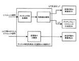
図1には、本発明の一実施形態に係る無線通信装置の構成を示している。 FIG. 1 shows a configuration of a wireless communication apparatus according to an embodiment of the present invention.
同図に示す無線通信装置は、2本の送受信アンテナ11a及び11bを備え、SVD−MIMO方式によるデータ伝送を行なうことができる。すなわち、送信時は、多重化する各送信信号に送信アンテナ重み係数を与え空間/時間符号して2本のアンテナ11a及び11bに分配してチャネルに送出し、受信側では、チャネル経由で2本のアンテナ11a及び11bにより受信した多重化信号に受信アンテナ重み係数を与え空間/時間復号して受信データを得る。但し、本発明の要旨はアンテナ2本に限定されるものではなく、3本以上であってもよい。 The wireless communication apparatus shown in the figure includes two transmission / reception antennas 11a and 11b, and can perform data transmission by the SVD-MIMO method. That is, at the time of transmission, a transmission antenna weighting coefficient is given to each transmission signal to be multiplexed, space / time code is performed, and the two antennas 11a and 11b are distributed and transmitted to the channel. Received antenna weights are given to the multiplexed signals received by the antennas 11a and 11b, and space / time decoding is performed to obtain received data. However, the gist of the present invention is not limited to two antennas, and may be three or more.
各送受信アンテナ11a及び11bには、スイッチ12a及び12bを介して、それぞれ送信系統並びに受信系統が並列的に接続され、他の無線通信装置宛に信号を所定の周波数チャネル上で無線送信し、あるいは他の無線通信装置から送られる信号を収集する。但し、スイッチ12a及び12bは送受信アンテナ11a及び11bを送信系統又は受信系統の一方と排他的に接続し、送受信をともに並行しては行なえないものとする。 Each transmission / reception antenna 11a and 11b is connected in parallel with a transmission system and a reception system via
各送信系統は、変調符号化部21と、送信用重み乗算部22と、IFFT23と、ブリアンブル/リファレンス付与部24と、D/A変換器25と、送信用アナログ処理部26を備えている。 Each transmission system includes a
変調符号化部21は、通信プロトコルの上位レイヤから送られてきた送信データを誤り訂正符号で符号化するとともに、BPSK、QPSK、16QAMなどの所定の変調方式により送信信号を信号空間上にマッピングする。この時点で、パイロット・シンボル挿入パターン並びにタイミングに従って、既知のデータ系列をパイロット・シンボルとして変調シンボル系列に挿入するようにしてもよい。サブキャリヤ毎あるいはサブキャリヤ数本の間隔で、既知パターンからなるパイロット信号が挿入される。 The
送信用重み乗算部22は、符号化後の送信信号を送信重み行列Vで乗算することにより、空間多重により複数のMIMOチャネルを得る。送信用重み行列Vは、通信相手から送られたフィードバック情報を基に構築され、送信用重み乗算部22に設定される。 The
IFFT23では、変調されたシリアル形式の信号を、並列キャリヤ数並びにタイミングに従って、並列キャリヤ数分のパラレル・データに変換してまとめた後、所定のFFTサイズ並びにタイミングに従ってFFTサイズ分の逆フーリエ変換を行なう。ここで、シンボル間干渉の除去のため、1OFDMシンボルの前後にガード・インターバル区間を設けるようにしてもよい。ガード・インターバルの時間幅は、伝搬路の状況、すなわち復調に影響を及ぼす遅延波の最大遅延時間によって決定される。そして、直列の信号に直し、周波数軸での各キャリヤの直交性を保持したまま時間軸の信号に変換して、送信信号とする。 In
プリアンブル/リファレンス付与部24は、RTS、CTS、DATAパケットなどの送信信号の先頭にプリアンブル信号やリファレンス信号を付加する。 The preamble /
無線通信装置がダウンリンク伝送の送信側として動作する場合、プリアンブル/リファレンス付与部24は、Vを送信用重みとして、受信側へダウンリンクで送るリファレンス信号をVで乗算する。 When the wireless communication apparatus operates as a transmission side of downlink transmission, the preamble /
また、無線通信装置がダウンリンク伝送の受信側として動作する場合、プリアンブル/リファレンス付与部24は、送信側へアップリンクで送るリファレンス信号をU*で乗算し、Uの共役行列U*をアップリンクの送信重みとして用いる。この場合、チャネル特性取得及び送信重み分離部37は、ダウンリンクの送信側から送られるリファレンス信号を用いてチャネル行列Hを取得し、さらにこれを特異値分解することで、送信機から受信機へのダウンリンクの送信重みV並びに受信重みUHを得て、U*をリファレンス信号用の送信重みとしてプリアンブル/リファレンス付与部24へ与える。チャネル特性取得及び送信重み分離部37の動作の詳細については、後述に譲る。Further, when the wireless communication apparatus operates as a reception side of downlink transmission, the preamble /
この送信信号は、D/A変換器25によりアナログのベースバンド信号に変換され、さらに送信用アナログ処理部26によりRF周波数帯にアップコンバートされてから、アンテナ11より各MIMOチャネルへ送出される。 This transmission signal is converted into an analog baseband signal by the D / A converter 25, further up-converted to an RF frequency band by the transmission analog processing unit 26, and then transmitted from the antenna 11 to each MIMO channel.
一方、各受信系統は、受信用アナログ処理部31と、A/D変換器32と、同期獲得部33と、FFT34と、受信用重み乗算部35と、復調復号器36と、チャネル特性取得及び送信重み分離部37で構成される。 On the other hand, each reception system includes a reception analog processing unit 31, an A / D converter 32, a
アンテナ11より受信した信号を、受信用アナログ処理部31でRF周波数帯からベースバンド信号にダウンコンバートし、A/D変換器32により、デジタル信号に変換する。 The signal received from the antenna 11 is down-converted from the RF frequency band to the baseband signal by the reception analog processing unit 31, and converted into a digital signal by the A / D converter 32.
次いで、同期獲得部33により検出された同期タイミングに従って、シリアル・データとしての受信信号をパラレル・データに変換してまとめ(ここでは、ガード・インターバルまでを含む1OFDMシンボル分の信号がまとめられる)、FFT34によって有効シンボル長分の信号をフーリエ変換し、各サブキャリヤの信号を取り出すことにより、時間軸の信号を周波数軸の信号に変換する。 Next, according to the synchronization timing detected by the
チャネル特性取得及び送信重み分離部37では、まず通信相手が多重化送信する信号毎に重みが与えられたリファレンス信号を用いてチャネル行列Hを得る。さらにこのチャネル行列Hを特異値分解して、送信用重み行列Vと、受信用重み行列UHと、対角行列Dを得ることができる。通信相手からは、所定の間隔でリファレンス信号が送られる場合には、チャネル特性取得及び送信重み分離部37はその都度新しいチャネル行列Hに更新し、これを特異値分解する。The channel characteristic acquisition and transmission
チャネル行列を特異値分解して得られた受信用重み行列UHは自装置の受信用重み乗算部35に設定されるとともに、送信用重み行列Vは通信相手にフィードバックされる。但し、受信用重み行列として、UHではなく、HVの逆行列としてのD-UHを用いるようにしてもよい(前述並びに式(8)を参照のこと)。また、得られた送信用重み行列Vを送信用重み乗算部22へ与える。The reception weight matrix UH obtained by singular value decomposition of the channel matrix is set in the reception
また、無線通信装置がダウンリンク伝送の受信側として動作する場合、チャネル特性取得及び送信重み分離部37では、チャネル行列Hを特異値分解して得られたUの共役行列U*をリファレンス信号用の送信重みとしてプリアンブル/リファレンス付与部24へ与える。When the wireless communication apparatus operates as a reception side of downlink transmission, the channel characteristic acquisition and transmission
また、チャネル特性取得及び送信重み分離部37では、特異値分解することなしに、送信用重みVを得ることができる。すなわち、無線通信装置がダウンリンク伝送の送信側として動作する場合には、受信側からU*で重み付けしたリファレンス信号をアップリンクで受信すると、アップリンクのチャネル行列がダウンリンクのチャネル行列のH(=UDVH)に対する転置行列HTとして表されることを利用し、HTU*=V*DUT=V*Dを得る。そして、ユニタリ行列の性質に基づいて、V*Dからダウンリンクの送信重みVを分離する。そして、得られた送信用重み行列Vを送信用重み乗算部22へ与える。In addition, the channel characteristic acquisition and transmission
チャネル特性取得及び送信重み分離部37の動作の詳細については、後述に譲る。 Details of the operation of the channel characteristic acquisition and transmission
受信用重み乗算部35は、チャネル行列Hを特異値分解して得られた受信用重み行列UH又はD-UHを受信信号に乗算することにより、空間多重された受信信号を空間分離する。The reception
重み付けされた受信信号は、さらに復調復号器36によって、信号空間上の受信信号をBPSK、QPSK、16QAMなどの所定の方式によりデマッピングするとともに、誤り訂正並びに復号して受信データとなり、通信プロトコルの上位レイヤに渡される。 The weighted received signal is further demodulated by a demodulator /
ここで、RTS/CTS手順に従いCSMA/CA通信方式に基づくアクセス動作を行なう場合、送受信機として動作する無線通信装置は、RTS、CTS、DATAの各パケットにチャネル行列取得用のリファレンス信号を付加し、リファレンス信号を用いて送受信重み成分を取得する。一般には、チャネル行列を特異値分解することにより重み行列を得ることができるが、特異値分解の計算は、多くの乗算器などを使用するため、実行時の消費電力も大きいという問題がある。本実施形態では、チャネル特性取得及び送信重み分離部37は、特異値分解することなしに、重み成分を取得することができる。 Here, when performing an access operation based on the CSMA / CA communication method according to the RTS / CTS procedure, the wireless communication device operating as a transceiver adds a channel matrix reference signal to each of the RTS, CTS, and DATA packets. The transmission / reception weight component is acquired using the reference signal. In general, a weight matrix can be obtained by performing singular value decomposition on a channel matrix. However, the calculation of singular value decomposition has a problem that power consumption during execution is large because many multipliers are used. In the present embodiment, the channel characteristic acquisition and transmission
図2には、チャネル特性取得及び送信重み分離部37の機能構成を模式的に示している。図示の通り、チャネル特性取得及び送信重み分離部37は、チャネル行列取得部と、特異値分解部と、送信重み分離部で構成される。 FIG. 2 schematically shows a functional configuration of the channel characteristic acquisition / transmission
チャネル行列取得部は、通信相手が多重化送信する信号毎に重みが与えられたリファレンス信号を用いてチャネル行列Hを得る。 The channel matrix acquisition unit obtains a channel matrix H using a reference signal weighted for each signal multiplexed and transmitted by the communication partner.
特異値分解部は、得られたチャネル行列Hを特異値分解して、送信用重み行列Vと、受信用重み行列UHと、対角行列Dを得る。得られた受信用重み行列UHは自装置の受信用重み乗算部35に設定されるとともに、送信用重み行列Vは通信相手にフィードバックされる。但し、受信用重み行列として、UHではなく、HVの逆行列としてのD-UHを用いるようにしてもよい(前述並びに式(8)を参照のこと)。また、チャネル行列Hを特異値分解して得られたUの共役行列U*をリファレンス信号用の送信重みとしてプリアンブル/リファレンス付与部24へ与える。The singular value decomposition unit performs singular value decomposition on the obtained channel matrix H to obtain a transmission weight matrix V, a reception weight matrix UH, and a diagonal matrix D. The obtained reception weight matrix UH is set in the reception
通信相手からは、所定の間隔でリファレンス信号が送られる場合には、チャネル特性取得及び送信重み分離部37はその都度新しいチャネル行列Hに更新し、これを特異値分解する。 When a reference signal is sent from a communication partner at a predetermined interval, the channel characteristic acquisition and transmission
送信重み分離部は、受信側からU*で重み付けしたリファレンス信号をアップリンクで受信すると、アップリンクのチャネル行列がダウンリンクのチャネル行列のH(=UDVH)に対する転置行列HTとして表されることを利用し、HTU*=V*DUT=V*Dを得る。そして、ユニタリ行列の性質に基づいて、V*Dからダウンリンクの送信重みVを分離する。そして、得られた送信用重み行列Vを送信用重み乗算部22へ与える。When the transmission weight separation unit receives a reference signal weighted by U* from the reception side on the uplink, the uplink channel matrix is represented as a transposed matrix HT with respect to H (= UDVH ) of the downlink channel matrix. by utilizing the fact, obtainH T U * = V * DU T = V * D. Then, the downlink transmission weight V is separated from V* D based on the property of the unitary matrix. Then, the obtained transmission weight matrix V is given to the transmission
ここで、送信重み分離部において、受信側からアップリンクで受信したU*で重み付けされたリファレンス信号から送信重みVを分離するための演算処理について説明する。但し、以下では、送信機から受信機へのダウンリンクを順方向とし、受信機から送信機へのアップリンクを逆方向とする。Here, calculation processing for separating the transmission weight V from the reference signal weighted by U* received from the reception side in the uplink in the transmission weight separation unit will be described. However, in the following, the downlink from the transmitter to the receiver is the forward direction, and the uplink from the receiver to the transmitter is the reverse direction.
この場合、順方向のチャネル行列は下式のように表される。但し送信機のアンテナ数をnとし、受信機のアンテナ数をmとする。また、送信機のj番目のアンテナから受信機のi番目のアンテナへの伝達関数をhijと表す。In this case, the forward channel matrix is expressed by the following equation. However, the number of antennas of the transmitter is n, and the number of antennas of the receiver is m. Further, a transfer function from the j-th antenna of the transmitter to the i-th antenna of the receiver is represented as hij .
これに対し、逆方向のチャネル行列は以下のように表される。 On the other hand, the channel matrix in the reverse direction is expressed as follows.
言い換えれば、逆方向のチャネル行列は、順方向のチャネル行列Hの転置行列HTとして表される。In other words, the reverse channel matrix is represented as a transposed matrix HT of the forward channel matrix H.
送信機からのリファレンス信号を用いて受信機側で順方向のチャネル行列Hを取得し、これを特異値分解すると下式の通りとなる。 When the reference channel signal from the transmitter is used to obtain the forward channel matrix H on the receiver side and this is singularly decomposed, the following equation is obtained.
したがって、受信機から送信機への逆方向のチャネル行列は下式の通りとなる。 Therefore, the channel matrix in the reverse direction from the receiver to the transmitter is as follows.
受信機は、送信機へアップリンクで送信するリファレンス信号に、送信用重みとして、順方向のチャネル行列Hを特異値分解して得られた行列Uの共役行列U*を送信重みに用いて送信する。The receiver transmits the reference signal transmitted in the uplink to the transmitter using the conjugate matrix U* of the matrix U obtained by singular value decomposition of the forward channel matrix H as the transmission weight as the transmission weight. To do.
この場合、送信機では、逆方向のチャネル行列HTにU*をかけてリファレンス信号を受信することになる。したがって、送信機は以下の式を得ることができる。In this case, the transmitter receives the reference signal by multiplying the reverse channel matrix HT by U* . Therefore, the transmitter can obtain the following equation:
ここで、V*DからVのみを分離することができれば、送信機側で特異値分解は不要になる。V*DからVとDを分離する方法について説明する。Here, if only V can be separated from V* D, the singular value decomposition is unnecessary on the transmitter side. A method for separating V and D from V* D will be described.
Vはユニタリ行列であり、MIMOチャネル数(=min[n,m])分の特異値ベクトルで構成されている。各固有ベクトルuはノルム1に正規化されている。 V is a unitary matrix, and is composed of singular value vectors for the number of MIMO channels (= min [n, m]). Each eigenvector u is normalized to norm 1.
したがって、受信機側で取得された一体となったUD=V*Dは、下式に示すように、各列にある固有ベクトルの要素に特異値をかけたものとなる。Therefore, the integrated UD = V* D acquired on the receiver side is obtained by multiplying the eigenvector element in each column by a singular value as shown in the following equation.
ここで、V*Dの列毎にその行列の要素のノルムを計算する。その列毎のノルムの大きさが行列Dの各対角要素となっているので、V*を分離することができる。Here, the norm of the matrix element is calculated for each column of V* D. Since the norm size for each column is a diagonal element of the matrix D, V* can be separated.
送信機側から、送信用重みとして、Vをリファレンス信号とその直後にユーザ・データを送信する。受信機側では、Vがかけられたリファレンス信号から、HVを得る。そのHVの逆行列を受信用の重みとして(式(8)を参照のこと)、ユーザ・データを受信する。 From the transmitter side, V is used as a transmission weight, and V is a reference signal and user data is transmitted immediately thereafter. On the receiver side, HV is obtained from the reference signal multiplied by V. The user data is received using the inverse matrix of the HV as a receiving weight (see equation (8)).
以上で述べた方法を用いると、特異値分解を1回、逆行列演算を1回だけ行なうことにより、特異値分解2回分と逆行列演算1回分と同じ結果を得ることができる。 When the method described above is used, the same result as two singular value decompositions and one inverse matrix operation can be obtained by performing singular value decomposition once and inverse matrix calculation only once.
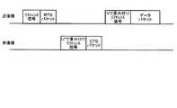
以下では、本実施形態に係る無線通信システムにおいて、RTS、CTS、DATAというMIMO通信を行なうための動作手順について、図3を参照しながら説明する。但し、送信機側で送信重み行列Vを取得するための処理は事前に行なわれているものとする。 Hereinafter, an operation procedure for performing MIMO communication such as RTS, CTS, and DATA in the wireless communication system according to the present embodiment will be described with reference to FIG. However, it is assumed that the process for acquiring the transmission weight matrix V on the transmitter side is performed in advance.
(ステップ1)
送信機から、受信機へリファレンス信号を送る。受信機では、チャネル行列Hを取得することができる。(Step 1)
A reference signal is sent from the transmitter to the receiver. In the receiver, the channel matrix H can be obtained.
(ステップ2)
受信機で、チャネル行列Hを特異値分解し(式(10)を参照のこと)、行列Uを取得する。(Step 2)
At the receiver, the channel matrix H is subjected to singular value decomposition (see equation (10)) to obtain the matrix U.
(ステップ3)
受信機から送信機へ、U*で重み付けしたリファレンス信号を送信する。(Step 3)
A reference signal weighted by U* is transmitted from the receiver to the transmitter.
(ステップ4)
送信機では、U*で重み付けされたリファレンス信号から、V*DUTU*=V*Dを取得する(式(13)を参照のこと)。(Step 4)
In the transmitter, from the reference signal weighted byU *, V * DU T U * = V * D to get (see equation (13)).
(ステップ5)
取得したV*Dの各列のノルムを計算することにより、これらを分離する。この結果、特異値分解することなしに、Dを取得することができ、Vも取得することができる。(Step 5)
These are separated by calculating the norm of each column of acquired V* D. As a result, D can be acquired without performing singular value decomposition, and V can also be acquired.
(ステップ6)
送信機側から、Vで重み付けしたリファレンス信号を送信し、その直後にユーザ・データを送信する。(Step 6)
A reference signal weighted with V is transmitted from the transmitter side, and user data is transmitted immediately thereafter.
(ステップ7)
受信機側では、送信機側からのVで重み付けしたリファレンス信号を受信することにより、チャネル行列HV=UDを取得する。(Step 7)
On the receiver side, a channel matrix HV = UD is obtained by receiving a reference signal weighted by V from the transmitter side.
(ステップ8)
受信機では、チャネル行列UDの逆行列を計算し、これを受信用の重みとして保持する。(Step 8)
The receiver calculates an inverse matrix of the channel matrix UD and holds this as a receiving weight.
(ステップ9)
ステップ8で求めた受信用の重みを用いて送信機から送信されたユーザ・データをデコードする。(Step 9)
The user data transmitted from the transmitter is decoded using the reception weight obtained in step 8.
以上、特定の実施形態を参照しながら、本発明について詳解してきた。しかしながら、本発明の要旨を逸脱しない範囲で当業者が該実施形態の修正や代用を成し得ることは自明である。 The present invention has been described in detail above with reference to specific embodiments. However, it is obvious that those skilled in the art can make modifications and substitutions of the embodiment without departing from the gist of the present invention.
本発明は、空間多重してデータ伝送を行なうさまざまな無線通信システムに適用することができる。すなわち、本発明の要旨は、SVD−MIMO方式のように空間分割すなわち空間直交した多重伝送方式に適用範囲は必ずしも限定されず、伝搬路状況から得られるチャネル行列Hに基づいて重み付け送受信する他の同様の通信システムに対しても本発明を好適に適用することができる。 The present invention can be applied to various wireless communication systems that perform data transmission by spatial multiplexing. In other words, the scope of the present invention is not necessarily limited to the spatial division, that is, the spatially orthogonal multiplex transmission scheme such as the SVD-MIMO scheme, and other weighted transmission / reception based on the channel matrix H obtained from the propagation path condition. The present invention can be preferably applied to similar communication systems.
要するに、例示という形態で本発明を開示してきたのであり、本明細書の記載内容を限定的に解釈するべきではない。本発明の要旨を判断するためには、冒頭に記載した特許請求の範囲の欄を参酌すべきである。 In short, the present invention has been disclosed in the form of exemplification, and the description of the present specification should not be interpreted in a limited manner. In order to determine the gist of the present invention, the claims section described at the beginning should be considered.
11…アンテナ
12…スイッチ
21…符号器
22…送信用重み乗算部
23…IFFT
24…ブリアンブル/リファレンス付与部
25…D/A変換器
26…送信用アナログ処理部
31…受信用アナログ処理部
32…A/D変換器
33…同期獲得部
34…FFT
35…受信用重み乗算部
36…復号器
37…チャネル特性取得及び送信重み分離部DESCRIPTION OF SYMBOLS 11 ... Antenna 12 ...
24 ... Breamble / reference adding unit 25 ... D / A converter 26 ... Analog processing unit for transmission 31 ... Analog processing unit for reception 32 ... A /
35 ... Receiving
Claims (3)
Translated fromJapanese前記第2の通信機は、前記第1の通信機からのリファレンス信号を用いてチャネル行列Hを取得し、特異値分解することにより送信機から受信機への第1の通信機から第2の通信機方向の送信重みV並びに受信重みUHを得て、Uの共役行列U*を第2の通信機から第1の通信機方向の送信重みとしてU*で重み付けしたリファレンス信号を第2の通信機から第1の通信機方向で送信し、
前記第1の通信機は、第1の通信機から第2の通信機方向のチャネル行列のH(=UDVH)に対する転置行列HTをチャネル行列に持つ第2の通信機から第1の通信機方向においてU*で重み付けしたリファレンス信号を受信すると、HTU*=V*DUT=V*Dを得て、さらにユニタリ行列の性質に基づいてV*Dから第1の通信機から第2の通信機方向の送信重みVを分離する、
ことを特徴とする無線通信システム。A wireless communication system that performs spatial multiplexing transmission by determining transmission weights and reception weights using a matrix UDVH obtained by singular value decomposition of a channel matrix H having elements corresponding to transmission and reception antenna pairs as elements.When performing data transmission from the first communication device to the second communication device,
The second communicator obtains a channel matrix H using the reference signal from the first communicator and performs singular value decomposition to obtain a second from the first communicator from the transmitter to the receiver. A transmission weight V in the direction of the communication device and a reception weight UH are obtained, and a reference signal obtained by weighting the conjugate matrix U* of U from the second communication device as a transmission weight in the first communication device direction with U* is set to the second value. Transmit from the communicator in the first communicator direction,
The first communicator performs the first communication from the second communicator having a transposed matrix HT for the channel matrix H (= UDVH ) from the first communicator to the second communicator in the channel matrix. When a reference signal weighted by U* is received in the machine direction, HT U* = V* DUT = V* D is obtained, and further, from V* D based on the properties of the unitary matrix, Separating the transmission weights V in the direction of the two communication devices,
A wireless communication system.
送信用の重みをかけたリファレンス信号を受信する受信手段と、
該受信した信号を基にこれとは逆方向の送信用の重み成分と対角行列の成分に分離する分離手段と、
前記分離手段により得られた送信用の重み成分を用いて前記リファレンス信号を受信したのとは逆方向のデータ送信を行なう送信手段と、
を具備し、
第2の通信機から当該無線通信装置方向は当該無線通信装置から第2の通信機方向のチャネル行列のH(=UDVH)の転置行列HTをチャネル行列に持ち、第2の通信機へデータ通信を行なう際に、
前記受信手段は、第2の通信機から当該無線通信装置方向においてU*で重み付けしたリファレンス信号を受信することにより、HTU*=V*DUT=V*Dを得て、
前記分離手段は、ユニタリ行列の性質に基づいて、V*Dから当該無線通信装置から第2の通信機方向の送信重みVを分離する、
ことを特徴とする無線通信装置。A wireless communication apparatus that performs spatial multiplexing transmission by determining a transmission weight and a reception weight using a channel matrix having a channel corresponding to each antenna pair of transmission and reception as elements,
Receiving means for receiving a weighted reference signal for transmission;
Separating means for separating into a weight component for transmission and a diagonal matrix component in the opposite direction based on the received signal;
Transmitting means for performing data transmission in the opposite direction to the reception of the reference signal using the transmission weight component obtained by the separating means;
Comprising
The direction from the second communication device to the wireless communication device has the transposed matrix HT of the channel matrix H (= UDVH ) of the channel communication direction from the wireless communication device to the second communication device in the channel matrix to the second communication device. When performing data communication,
The receiving means receives HT U* = V* DUT = V* D by receiving a reference signal weighted with U* in the direction of the wireless communication device from the second communication device,
The separating means separates the transmission weight V in the second communication device direction from the wireless communication device from V* D based on the property of the unitary matrix.
A wireless communication device.
Uの共役行列U*を第2の通信機から第1の通信機方向の送信重みとしてU*で重み付けされたリファレンス信号を受信し、HTU*=V*DUT=V*Dを取得する受信ステップと、
ユニタリ行列の性質に基づいて、V*Dから第1の通信機から第2の通信機方向の送信重みVを分離する分離ステップと、
Vを用いて第1の通信機から第2の通信機方向の重み付け送信を行なう送信ステップと、
を有することを特徴とする無線通信方法。
This is a wireless communication method for performing spatial multiplexing transmission by determining transmission weights and reception weights using a matrix UDVH obtained by singular value decomposition of a channel matrix H whose elements are channels corresponding to transmission / reception antenna pairs. Thus, the communication direction from the second communication device has the transposed matrix HT of the channel matrix H (= UDVH ) of the communication direction to the second communication device in the channel matrix, and data communication to the second communication device When doing
The reference signal weighted with U* is received from the second communication device using the conjugate matrix U* of U as the transmission weight in the first communication device direction, and HT U* = V* DUT = V* D is obtained. Receiving step to
A separation step of separating the transmission weight V in the direction of the second communication device from the first communication device from V* D based on the property of the unitary matrix;
A transmission step of performing weighted transmission in the direction of the second communication device from the first communication device using V;
A wireless communication method comprising:
Priority Applications (7)
| Application Number | Priority Date | Filing Date | Title |
|---|---|---|---|
| JP2004140485AJP4604545B2 (en) | 2004-05-10 | 2004-05-10 | Wireless communication system, wireless communication apparatus, and wireless communication method |
| US11/000,192US7620114B2 (en) | 2004-05-10 | 2004-12-01 | System, method, apparatus, and computer program for wireless communication |
| CN2005800036479ACN1914842B (en) | 2004-05-10 | 2005-04-18 | Systems, methods and devices for wireless communications |
| BRPI0510766-0ABRPI0510766A (en) | 2004-05-10 | 2005-04-18 | wireless communication system and apparatus, wireless communication method, and, computer program |
| EP05734757AEP1745579A1 (en) | 2004-05-10 | 2005-04-18 | System, method, apparatus, and computer program for wireless communication |
| KR1020067020013AKR101176432B1 (en) | 2004-05-10 | 2005-04-18 | System, method, and apparatus for wireless communication |
| PCT/JP2005/007746WO2005109721A1 (en) | 2004-05-10 | 2005-04-18 | System, method, apparatus, and computer program for wireless communication |
Applications Claiming Priority (1)
| Application Number | Priority Date | Filing Date | Title |
|---|---|---|---|
| JP2004140485AJP4604545B2 (en) | 2004-05-10 | 2004-05-10 | Wireless communication system, wireless communication apparatus, and wireless communication method |
Publications (2)
| Publication Number | Publication Date |
|---|---|
| JP2005323216A JP2005323216A (en) | 2005-11-17 |
| JP4604545B2true JP4604545B2 (en) | 2011-01-05 |
Family
ID=35456588
Family Applications (1)
| Application Number | Title | Priority Date | Filing Date |
|---|---|---|---|
| JP2004140485AExpired - Fee RelatedJP4604545B2 (en) | 2004-05-10 | 2004-05-10 | Wireless communication system, wireless communication apparatus, and wireless communication method |
Country Status (3)
| Country | Link |
|---|---|
| US (1) | US7620114B2 (en) |
| JP (1) | JP4604545B2 (en) |
| CN (1) | CN1914842B (en) |
Families Citing this family (42)
| Publication number | Priority date | Publication date | Assignee | Title |
|---|---|---|---|---|
| JP4543737B2 (en)* | 2004-05-10 | 2010-09-15 | ソニー株式会社 | Wireless communication system, wireless communication apparatus, wireless communication method, and computer program |
| KR100782925B1 (en)* | 2004-12-15 | 2007-12-07 | 삼성전자주식회사 | Multi-antenna communication system |
| US7768988B2 (en)* | 2005-02-22 | 2010-08-03 | Intel Corporation | Method and apparatus to perform network medium reservation in a wireless network |
| AR055163A1 (en)* | 2005-09-13 | 2007-08-08 | Iwics Inc | DETERMINATION OF THE POSITION OF MOBILE STATIONS IN A WIRELESS NETWORK |
| US7653163B2 (en)* | 2005-10-26 | 2010-01-26 | Intel Corporation | Systems for communicating using multiple frequency bands in a wireless network |
| US7720036B2 (en)* | 2005-10-26 | 2010-05-18 | Intel Corporation | Communication within a wireless network using multiple frequency bands |
| US8340071B2 (en)* | 2005-10-26 | 2012-12-25 | Intel Corporation | Systems for communicating using multiple frequency bands in a wireless network |
| US20070099669A1 (en)* | 2005-10-26 | 2007-05-03 | Sadri Ali S | Communication signaling using multiple frequency bands in a wireless network |
| US9084260B2 (en) | 2005-10-26 | 2015-07-14 | Intel Corporation | Systems for communicating using multiple frequency bands in a wireless network |
| US8483761B2 (en)* | 2006-01-18 | 2013-07-09 | Intel Corporation | Singular value decomposition beamforming for a multiple-input-multiple-output communication system |
| JP5427025B2 (en)* | 2006-03-20 | 2014-02-26 | コーニンクレッカ フィリップス エヌ ヴェ | Signal quality report |
| US20080003948A1 (en)* | 2006-06-29 | 2008-01-03 | Patrick Mitran | Calibration systems and techniques for distributed beamforming |
| JP5006001B2 (en)* | 2006-08-22 | 2012-08-22 | 株式会社エヌ・ティ・ティ・ドコモ | Downlink MIMO transmission control method and base station apparatus |
| KR101163280B1 (en) | 2006-10-03 | 2012-07-10 | 인터디지탈 테크날러지 코포레이션 | Combined open loop/closed loop cqi-based uplink transmit power control with interference mitigation for e-utra |
| US7697959B2 (en)* | 2006-10-10 | 2010-04-13 | Intel Corporation | Adaptive multiple-antenna systems with omni-directional and sector-directional antenna modes |
| US20080089432A1 (en)* | 2006-10-16 | 2008-04-17 | Samsung Electronics Co., Ltd. | Apparatus and method for beamforming in a multiple-input multiple-output system |
| JP4840088B2 (en)* | 2006-11-08 | 2011-12-21 | ソニー株式会社 | Wireless communication system, wireless communication apparatus, and wireless communication method |
| US20080117865A1 (en)* | 2006-11-17 | 2008-05-22 | Li Guoqing C | Communication in a wireless network using multiple antennae |
| US7689171B2 (en)* | 2006-11-27 | 2010-03-30 | Intel Corporation | Reducing interference in a wireless network via antenna selection |
| US8509836B2 (en) | 2007-03-07 | 2013-08-13 | Interdigital Technology Corporation | Combined open loop/closed loop method for controlling uplink power of a mobile station |
| KR100932260B1 (en)* | 2007-05-31 | 2009-12-16 | 한국전자통신연구원 | Decoding device and method for multiple input multiple output system |
| KR101098096B1 (en) | 2007-09-06 | 2011-12-26 | 후지쯔 가부시끼가이샤 | Mobile communication system using adaptive multiantenna |
| WO2010005997A2 (en)* | 2008-07-07 | 2010-01-14 | Wi-Lan, Inc. | Closed form singular value decomposition |
| US8320492B2 (en)* | 2008-07-07 | 2012-11-27 | Wi-Lan Inc. | Closed form singular value decomposition |
| US20110242962A1 (en)* | 2008-10-28 | 2011-10-06 | Hitachi, Ltd. | Method of Multiuser Mimo Wireless Communication and Device of Multiuser Mimo Wireless Communication |
| JP5540592B2 (en) | 2009-07-23 | 2014-07-02 | ソニー株式会社 | COMMUNICATION SYSTEM, COMMUNICATION CONTROL METHOD, MOBILE TERMINAL, AND RELAY DEVICE |
| JP5909843B2 (en) | 2009-08-10 | 2016-04-27 | ソニー株式会社 | COMMUNICATION SYSTEM, COMMUNICATION DEVICE, COMMUNICATION METHOD, AND COMPUTER PROGRAM |
| JP2011066874A (en) | 2009-08-17 | 2011-03-31 | Sony Corp | Communication system, communication apparatus, communication method, and computer program |
| JP2011071963A (en) | 2009-08-26 | 2011-04-07 | Sony Corp | Communication system, apparatus and method and computer program |
| US9148205B2 (en)* | 2010-01-25 | 2015-09-29 | Qualcomm Incorporated | Feedback for supporting SU-MIMO and MU-MIMO operation in wireless communication |
| EP2557747B1 (en) | 2010-04-07 | 2019-02-13 | Alcatel Lucent | Method and apparatus for feeding back and constructing correlation matrix in multi-input multi-output system |
| US20120009961A1 (en)* | 2010-07-08 | 2012-01-12 | Ralink Technology (Singapore) Corporation Pte. Ltd. | Method and apparatus for beamforming in a wireless communication system |
| JP5585306B2 (en) | 2010-08-25 | 2014-09-10 | ソニー株式会社 | BASE STATION, RADIO COMMUNICATION DEVICE, RADIO COMMUNICATION SYSTEM, RADIO COMMUNICATION METHOD, AND PROGRAM |
| EP2725731B1 (en) | 2011-09-16 | 2018-07-18 | Nippon Telegraph And Telephone Corporation | Wireless communication method and base-station device |
| CN103138822B (en) | 2011-12-05 | 2017-04-12 | 华为技术有限公司 | Method and device of signal transmission |
| JP6023673B2 (en)* | 2012-12-18 | 2016-11-09 | 日本電信電話株式会社 | Wireless communication system and weight calculation method |
| JP5958591B2 (en)* | 2015-04-14 | 2016-08-02 | ソニー株式会社 | Mobile station, base station and radio communication method |
| US10587353B2 (en) | 2016-02-19 | 2020-03-10 | Hewlett Packard Enterprise Development Lp | MU-MIMO group assignment |
| CN106936533B (en)* | 2017-05-15 | 2018-12-21 | 苏州大学 | A kind of wireless signal transmission method and system |
| US10505609B2 (en) | 2017-06-14 | 2019-12-10 | Commscope Technologies Llc | Small cell beam-forming antennas |
| CN110799995A (en)* | 2017-06-29 | 2020-02-14 | 首选网络株式会社 | Data recognizer training method, data recognizer training device, program, and training method |
| WO2020248108A1 (en)* | 2019-06-11 | 2020-12-17 | 华为技术有限公司 | Data transmission method and device |
Family Cites Families (10)
| Publication number | Priority date | Publication date | Assignee | Title |
|---|---|---|---|---|
| US6097771A (en) | 1996-07-01 | 2000-08-01 | Lucent Technologies Inc. | Wireless communications system having a layered space-time architecture employing multi-element antennas |
| US6058105A (en)* | 1997-09-26 | 2000-05-02 | Lucent Technologies Inc. | Multiple antenna communication system and method thereof |
| US20030031264A1 (en)* | 2001-08-07 | 2003-02-13 | Barry John R. | System and method for adaptive channel diagonalization for array-to-array wireless communications |
| US20040192218A1 (en)* | 2003-03-31 | 2004-09-30 | Oprea Alexandru M. | System and method for channel data transmission in wireless communication systems |
| US7746967B2 (en)* | 2003-04-30 | 2010-06-29 | Intel Corporation | Beam-former and combiner for a multiple-antenna system |
| JP4337507B2 (en)* | 2003-11-05 | 2009-09-30 | ソニー株式会社 | Wireless communication system, wireless communication apparatus and wireless communication method, and computer program |
| US7680461B2 (en)* | 2003-11-05 | 2010-03-16 | Sony Corporation | Wireless communications system, wireless communications method, and wireless communications apparatus |
| JP2005184730A (en)* | 2003-12-24 | 2005-07-07 | Sony Corp | Wireless communication system, wireless communication apparatus, wireless communication method, and computer program |
| JP4543737B2 (en)* | 2004-05-10 | 2010-09-15 | ソニー株式会社 | Wireless communication system, wireless communication apparatus, wireless communication method, and computer program |
| JP4746420B2 (en)* | 2004-12-27 | 2011-08-10 | 株式会社東芝 | Wireless communication apparatus and method |
- 2004
- 2004-05-10JPJP2004140485Apatent/JP4604545B2/ennot_activeExpired - Fee Related
- 2004-12-01USUS11/000,192patent/US7620114B2/enactiveActive
- 2005
- 2005-04-18CNCN2005800036479Apatent/CN1914842B/ennot_activeExpired - Fee Related
Also Published As
| Publication number | Publication date |
|---|---|
| CN1914842A (en) | 2007-02-14 |
| US20050249151A1 (en) | 2005-11-10 |
| CN1914842B (en) | 2010-09-08 |
| US7620114B2 (en) | 2009-11-17 |
| JP2005323216A (en) | 2005-11-17 |
Similar Documents
| Publication | Publication Date | Title |
|---|---|---|
| JP4604545B2 (en) | Wireless communication system, wireless communication apparatus, and wireless communication method | |
| JP4543737B2 (en) | Wireless communication system, wireless communication apparatus, wireless communication method, and computer program | |
| JP4604798B2 (en) | Wireless communication system, wireless communication apparatus, wireless communication method, and computer program | |
| US10673655B2 (en) | Wireless communications system, wireless communications apparatus, wireless communications method and computer program for wireless communication | |
| JP4433867B2 (en) | Wireless communication system | |
| US7688910B2 (en) | Wireless communication system, wireless communication apparatus, wireless communication method, and computer program | |
| JP2005184730A (en) | Wireless communication system, wireless communication apparatus, wireless communication method, and computer program | |
| EP1559209A2 (en) | Channel estimation and spatial processing for tdd mimo systems | |
| JP4474934B2 (en) | Wireless communication system, wireless communication apparatus, wireless communication method, and computer program | |
| JP4576877B2 (en) | Wireless communication system, wireless communication apparatus, wireless communication method, and computer program | |
| JP4765336B2 (en) | Wireless communication apparatus and wireless communication method | |
| JP2006229503A (en) | Radio communication apparatus, radio communication method, and radio communication system | |
| KR101176432B1 (en) | System, method, and apparatus for wireless communication | |
| KR101098215B1 (en) | Wireless communication system, wireless communication device and wireless communication method, and recording medium |
Legal Events
| Date | Code | Title | Description |
|---|---|---|---|
| A621 | Written request for application examination | Free format text:JAPANESE INTERMEDIATE CODE: A621 Effective date:20070419 | |
| A977 | Report on retrieval | Free format text:JAPANESE INTERMEDIATE CODE: A971007 Effective date:20100125 | |
| A131 | Notification of reasons for refusal | Free format text:JAPANESE INTERMEDIATE CODE: A131 Effective date:20100309 | |
| A521 | Request for written amendment filed | Free format text:JAPANESE INTERMEDIATE CODE: A523 Effective date:20100430 | |
| A131 | Notification of reasons for refusal | Free format text:JAPANESE INTERMEDIATE CODE: A131 Effective date:20100622 | |
| A521 | Request for written amendment filed | Free format text:JAPANESE INTERMEDIATE CODE: A523 Effective date:20100708 | |
| TRDD | Decision of grant or rejection written | ||
| A01 | Written decision to grant a patent or to grant a registration (utility model) | Free format text:JAPANESE INTERMEDIATE CODE: A01 Effective date:20100907 | |
| A01 | Written decision to grant a patent or to grant a registration (utility model) | Free format text:JAPANESE INTERMEDIATE CODE: A01 | |
| A61 | First payment of annual fees (during grant procedure) | Free format text:JAPANESE INTERMEDIATE CODE: A61 Effective date:20100920 | |
| FPAY | Renewal fee payment (event date is renewal date of database) | Free format text:PAYMENT UNTIL: 20131015 Year of fee payment:3 | |
| LAPS | Cancellation because of no payment of annual fees |