JP4604518B2 - Game equipment with LCD display function - Google Patents
Game equipment with LCD display functionDownload PDFInfo
- Publication number
- JP4604518B2 JP4604518B2JP2004066809AJP2004066809AJP4604518B2JP 4604518 B2JP4604518 B2JP 4604518B2JP 2004066809 AJP2004066809 AJP 2004066809AJP 2004066809 AJP2004066809 AJP 2004066809AJP 4604518 B2JP4604518 B2JP 4604518B2
- Authority
- JP
- Japan
- Prior art keywords
- liquid crystal
- crystal display
- see
- color filter
- filter layer
- Prior art date
- Legal status (The legal status is an assumption and is not a legal conclusion. Google has not performed a legal analysis and makes no representation as to the accuracy of the status listed.)
- Expired - Fee Related
Links
Images


Landscapes
- Slot Machines And Peripheral Devices (AREA)
- Liquid Crystal (AREA)
Description
Translated fromJapanese本発明は、液晶表示機能付き遊戯装置に関し、特に装飾やゲーム内容を表示するカラーフィルターを積層した液晶表示パネルの背面にバックライトを設け、液晶表示パネルに該液晶表示パネルの前方からバックライトの後方に配された回転表示体を見えるようにするための透視部を設けてなる液晶表示機能付き遊戯装置に関するものである。 The present invention relates to a game device with a liquid crystal display function, and in particular, a backlight is provided on the back of a liquid crystal display panel on which color filters for displaying decorations and game contents are stacked, and the backlight is placed on the liquid crystal display panel from the front of the liquid crystal display panel. The present invention relates to a game apparatus with a liquid crystal display function provided with a see-through part for allowing a rotary display body arranged behind to be seen.
遊戯装置であるスロットマシンは、例えば3個の回転表示体を化粧板に形成した開口部を介して前面から見えるようにし、回転表示体に施した絵柄や数字等のシンボルマークを所定の組み合わせになるように操作して楽しむものである。具体的には、遊戯者が回転表示体を高速に回転させた後に手動で適宜に停止させて目的とするシンボルマークの組み合わせを得て楽しむものである。 A slot machine, which is an amusement device, for example, allows three rotary display bodies to be seen from the front through an opening formed in a decorative board, and symbol marks such as patterns and numbers applied to the rotary display bodies are combined in a predetermined combination. It is something that you can enjoy by operating. Specifically, after the player rotates the rotary display body at a high speed, the player manually stops it appropriately and obtains a desired combination of symbol marks.
近年のスロットマシンは、化粧板に施された装飾を変化させたり、ゲーム内容を表示するために液晶表示部が備えられている。例えば、下記の特許文献1にはゲームの目的とする入賞の組み合わせに該当する絵柄を遊戯者に分かりやすく表示できるようにしたスロットマシンが開示されている。この特許文献1に開示されているスロットマシンの表示面は、液晶シャッターにて形成される表示窓と、その表示窓を透明とするか不透明とするかの制御を行わせるための制御部とからなり、表示窓は絵柄を施した回転リールの前方に位置し、その表示窓を介してそれぞれの回転リールの絵柄が見えるように形成されている。 Recent slot machines are provided with a liquid crystal display unit for changing decorations on the decorative board and displaying game contents. For example, Patent Document 1 below discloses a slot machine that can display a picture corresponding to a winning combination as an object of a game in an easy-to-understand manner for a player. The display surface of the slot machine disclosed in Patent Document 1 includes a display window formed by a liquid crystal shutter and a control unit for controlling whether the display window is transparent or opaque. Thus, the display window is located in front of the rotating reels with the image and is formed so that the image of each rotating reel can be seen through the display window.
前記制御部は、液晶シャッターである表示窓を透明とするか不透明とするかについて、回転リールの各絵柄毎に制御できるように形成され、且つ、入賞の組み合わせの絵柄に対応する表示窓の区分のみを透明とすることができるように制御可能にしたものである。 The control unit is formed so that it can be controlled for each picture of the rotating reel as to whether the display window, which is a liquid crystal shutter, is transparent or opaque, and the display window classification corresponding to the winning combination picture It is controllable so that only can be made transparent.
この場合、表示窓は回転リールの前方に位置し、その表示窓には各回転リールの絵柄が3個ずつ、即ち9個の絵柄が見えるように形成されているので、前記制御部は表示窓の9箇所を個別に制御することができるようになっている。 In this case, the display window is located in front of the rotating reel, and the display window is formed so that three patterns of each rotating reel, that is, nine patterns can be seen. These nine locations can be individually controlled.
このスロットマシンにおいて、前記制御部は、ゲーム開始時には表示窓の全ての部分を透明とするように制御し、ゲーム終了時に入賞の絵柄の組み合わせがある場合にはこの部分のみ透明とし、入賞の組み合わせに無関係な絵柄に対応する表示窓の部分を不透明にするように制御する。この従来のスロットマシンの液晶表示パネルは、単に液晶シャッターとして使用され、遮光状態及び透光状態に制御されるのみである。 In this slot machine, the control unit controls all parts of the display window to be transparent at the start of the game, and when there is a combination of winning pictures at the end of the game, only this part is transparent, The display window corresponding to the pattern irrelevant to the control is controlled to be opaque. The liquid crystal display panel of this conventional slot machine is simply used as a liquid crystal shutter and is controlled only in a light shielding state and a light transmitting state.
一方、下記特許文献2には、スロットマシンの前面の装飾を変化させたりゲーム内容を表示するために液晶表示装置を備えたものが開示されている。 On the other hand, Patent Document 2 below discloses a liquid crystal display device provided for changing the decoration on the front surface of the slot machine or displaying game contents.
この従来技術のスロットマシンにおける液晶表示パネルは、スロットマシンのゲームに関連した次の(1)〜(3)等の各種表示を行うことができるようになっている。
(1)ゲームの開始前に、ゲーム方法等の各種インフォメーションを液晶表示できるようにしたこと。
(2)メダルの投入枚数に応じて従来の固定ラインを廃し、新たに設けた有効ラインを遊戯者に見易く表示できるようにしたこと。
(3)従来の回転リールを使用したゲームに加え、液晶を利用した別遊戯ができるようにしたこと。The liquid crystal display panel in the slot machine according to the prior art can perform various displays (1) to (3) related to the game of the slot machine.
(1) Before starting the game, various information such as game methods can be displayed on a liquid crystal display.
(2) The conventional fixed line is abolished according to the number of inserted medals, and the newly provided effective line can be displayed in an easy-to-read manner for the player.
(3) In addition to a game using a conventional rotating reel, another game using liquid crystal can be performed.
すなわち、下記特許文献2に開示されているスロットマシンにおける液晶表示パネルは、スロットマシンのセンターパネル裏面のほぼ全体にわたって配置され、この液晶表示パネルの裏面には該液晶表示パネルを裏面から照明するバックライトユニットが配置され、また、このバックライトユニットは3個の表示窓を除き液晶表示パネルの裏面の略全体にわたって配置された面発光板及び該面発光板の端面に配置された蛍光灯とからなっている。 That is, the liquid crystal display panel in the slot machine disclosed in Patent Document 2 below is disposed over almost the entire back surface of the center panel of the slot machine, and the back surface of the liquid crystal display panel is a back light that illuminates the liquid crystal display panel from the back surface. A light unit is disposed, and the backlight unit includes a surface light emitting plate disposed over substantially the entire back surface of the liquid crystal display panel except for three display windows, and a fluorescent lamp disposed on an end surface of the surface light emitting plate. It has become.
従って、このスロットマシンでは、面発光板を各表示窓の位置を除いて配置したことから、液晶表示パネルの状態の如何にかかわらずスロットマシンの内部に配置された各回転リールのシンボルマークをセンターパネルを介してスロットマシンの前面より見ることができるようになされている。 Therefore, in this slot machine, the surface light-emitting plates are arranged excluding the positions of the display windows, so that the symbol mark of each rotary reel arranged inside the slot machine is centered regardless of the state of the liquid crystal display panel. It can be seen from the front of the slot machine through the panel.
このスロットマシンの液晶表示パネルでは、前記(1)の場合は、まず、ゲーム開始前に液晶を遮光状態とする。このため、センターパネルの前面からは、各回転リールのシンボルマークが見えない。この遮光状態においては、その遮光面の液晶表示パネルにゲームの使用方法等の各種のインフォメーションを表示することが可能である。 In the liquid crystal display panel of this slot machine, in the case of (1), first, the liquid crystal is put in a light-shielding state before the game is started. For this reason, the symbol mark of each rotary reel cannot be seen from the front surface of the center panel. In this light shielding state, various information such as how to use the game can be displayed on the liquid crystal display panel on the light shielding surface.
また、前記(2)の場合は、メダルを投入する等してゲーム開始となると、表示窓の液晶部分が透光状態となる。このため、センターパネルの前面より、内部の各回転リールのシンボルマークを見ることができる。これに加え、液晶の表示面の一部に投入されたコイン数に対応した有効ラインを表示する。この有効ラインは一回のゲームでのメダルの投入枚数によって異なるようにすることができる。 In the case of (2), when the game is started by inserting a medal or the like, the liquid crystal part of the display window becomes translucent. For this reason, the symbol mark of each internal reel can be seen from the front surface of the center panel. In addition to this, an effective line corresponding to the number of coins inserted into a part of the display surface of the liquid crystal is displayed. This effective line can be made different depending on the number of medals inserted in one game.
前記(3)の場合は、例えばゲーム終了の結果、特別の入賞態様になったときに、表示窓の部分を遮光状態とし、その遮光面において別遊戯を自由に表示することができる。 In the case of (3), for example, when a special winning mode is achieved as a result of the end of the game, the display window portion can be in a light-shielding state, and another game can be freely displayed on the light-shielding surface.
一方、本出願人は、特願2003−288312号として、カラーフィルターを設けた液晶表示器を有する遊戯装置用表示器に関する発明(以下、先願発明という)を特許出願している。この先願発明は、液晶表示器の後方に表面に絵柄、数字を施した回転表示体を配し、この回転表示体を液晶表示器の前方から判読するための構成として、液晶表示器には透視部を設けている。 On the other hand, the present applicant has filed a patent application for a game device display device (hereinafter referred to as a prior application invention) having a liquid crystal display provided with a color filter as Japanese Patent Application No. 2003-288212. In the invention of the prior application, a rotary display body having a pattern and a number on the surface is arranged behind the liquid crystal display, and the rotary display body is seen through the liquid crystal display as a configuration for reading from the front of the liquid crystal display. Is provided.
併せて、遊戯用としての目的のために、透視部を除いた液晶表示器の部分には表示内容を可変して表示する装飾用表示部が設けられている。また、装飾用表示部と透視部とはそれぞれ構成を異にするカラーフィルターを有するものである。 In addition, for the purpose of playing, a display unit for decoration that displays the display contents in a variable manner is provided in the portion of the liquid crystal display excluding the see-through unit. Further, the decorative display section and the fluoroscopic section have color filters having different configurations.
この先願発明においては、遊戯前は、液晶表示器が装飾用表示部においてカラーによる可変表示を行なうが、透視部においては不透明となり回転表示体が目視できないようになっている。遊戯開始後は、透視部が透光状態となって回転表示体を目視できるように駆動される。この際の透視部におけるカラーフィルターによる色付けの影響は、R、G、Bのサブピクセルが極めて小さいために遊戯者にとっては全体的に白っぽく見えるだけである。
このようにスロットマシンの使用状況に応じて液晶表示パネルの表示状態を変更させる技術が知られている。しかしながら、前記特許文献2に示す従来技術にあっては、表示窓を用いてカラー表示を行なうことにより多くの表示を可能としたとしても、ゲーム中に表示窓を形成して回転リールのシンボルマークを見る場合には、カラーフィルター層の存在により透光性が悪く、そのため、ゲーム中の回転リールのシンボルマークが見難くなってしまう。従って、ゲーム中に高速に変化するシンボルマークを注視する遊戯者にとっては極めて大きな問題点となっている。 As described above, a technique for changing the display state of a liquid crystal display panel in accordance with the usage state of a slot machine is known. However, in the prior art disclosed in Patent Document 2, even if a large number of displays are possible by performing color display using the display window, the display window is formed during the game and the symbol mark of the rotating reel is formed. In the case of seeing, the translucency is poor due to the presence of the color filter layer, which makes it difficult to see the symbol mark of the rotating reel in the game. Therefore, it is a very big problem for a player who watches a symbol mark that changes at high speed during the game.
一方、前記先願発明にあっては、液晶表示器を装飾表示部と透視部とによって形成してそれぞれを独立に駆動させることができるとしても、前記特許文献2に示す従来技術と同様に、透視部を透光状態にしたときのカラーフィルター層の透光性に対する悪影響を解決するには至っていない。加えて、遊戯装置の種類によっては、透視部の表示を強調するためや鮮明に表示するために所望の色の濃さでカラー表示を行いたいという要求もある。 On the other hand, in the prior invention, even if the liquid crystal display can be formed by the decorative display portion and the fluoroscopic portion and each can be driven independently, as in the prior art shown in Patent Document 2, It has not yet been solved the adverse effect on the translucency of the color filter layer when the see-through portion is in a translucent state. In addition, depending on the type of game machine, there is a demand for color display with a desired color intensity in order to emphasize the display of the fluoroscopic part or to display it clearly.
そこで、本発明は、従来の問題点を排除し、ゲーム開始前には液晶表示パネルの全面に亘ってカラーで所望の表示を行ない、ゲーム開始後には透視部から後方にある回転表示体を見易くしたり、所望に応じて透視部のカラー表示を強調して表示し得る液晶表示機能付き遊戯装置を提供することを目的とする。 Therefore, the present invention eliminates the conventional problems, performs desired display in color over the entire surface of the liquid crystal display panel before the game starts, and makes it easy to see the rotary display body behind the fluoroscopic part after the game starts. It is an object of the present invention to provide a game apparatus with a liquid crystal display function that can display the color display of a fluoroscopic part with emphasis as desired.
前記課題を解決するために、本願の請求項1に係る液晶表示機能付き遊戯装置の発明は、カラーフィルター層を有する液晶表示パネルと、前記液晶表示パネルの背面に設けられたバックライトと、前記バックライトの後方に配された回転表示体と、前記液晶表示パネルに設けられ、該液晶表示パネルの前方から前記回転表示体を見えるようにするための透視部を有する液晶表示機能付き遊戯装置において、前記カラーフィルター層は、前記透視部に位置する第1部分のカラーフィルター層と透視部以外の第2部分のカラーフィルター層の透光性が異なっており、前記透視部に位置する第1部分のカラーフィルター層は、前記透視部以外の第2部分のカラーフィルター層と同じ厚さであり、前記透視部に位置する第1部分のカラーフィルター層にはサブピクセル単位で孔が設けられ、前記孔は前記サブピクセルの略中央に形成されており、前記孔内には透明部材が充填されて前記サブピクセル全体にわたり均一な厚さとされ、前記サブピクセルを囲んで設けられるブラックマトリクスは、前記透視部に位置する第1部分のカラーフィルター層よりも薄い厚さで形成されており、前記透視部に位置する第1部分の前記ブラックマトリクスと前記カラーフィルターとの間に前記透明部材が充填されて、前記第1部分全体にわたり均一な厚さとされていて、前記液晶パネルの前記背面側には、前記透視部に位置する第1部材に対応する位置に、プリズムシートおよび拡散シートを積層してなる光学シートが配置されていることを特徴とする。In order to solve the above-mentioned problem, the invention of the game device with a liquid crystal display function according to claim 1 of the present application includes a liquid crystal display panel having a color filter layer, a backlight provided on the back surface of the liquid crystal display panel, In a game apparatus with a liquid crystal display function, comprising: a rotary display disposed behind a backlight; and a liquid crystal display panel provided on the liquid crystal display panel and having a see-through portion for allowing the rotary display to be seen from the front of the liquid crystal display panel , the color filter layer, saidhas translucent propertiesTsu Do different first partial color filter layer and a color filter layer of the second portion other than the transparent part of which is located in perspectivesection, the first located at the see-through portion The color filter layer of the part has the same thickness as the color filter layer of the second part other than the fluoroscopic part, and the color filter layer of the first part located in the fluoroscopic part Each of the subpixels is provided with a hole, and the hole is formed substantially at the center of the subpixel, and the hole is filled with a transparent member to have a uniform thickness over the subpixel. The black matrix provided around the first portion is formed with a thickness thinner than the color filter layer of the first portion located in the see-through portion, and the black matrix and the color filter of the first portion located in the see-through portion The transparent member is filled between the liquid crystal panel and the first portion so as to have a uniform thickness, and on the back side of the liquid crystal panel, a position corresponding to the first member located in the see-through portion is provided. An optical sheet formed by laminating a prism sheet and a diffusion sheet is disposed .
また、本願の請求項2に係る補正は、前記請求項1に記載の液晶表示機能付き遊戯装置において、前記液晶パネルの前記背面側には、前記透視部に位置する第1部材に対応する位置に、プリズムシートおよび拡散シートを積層してなる光学シートが配置されていることを特徴とする。Further, in the game device with a liquid crystal display function according to claim 1, the correction according to claim 2 of the present application isa position corresponding to the first member located in the see-through portion on the back side of the liquid crystal panel. Further, an optical sheet formed by laminating a prism sheet and a diffusion sheet is arranged .
本願発明は上記の構成を備えることにより以下のような優れた効果を奏する。すなわち、本願の請求項1に係る液晶表示機能付き遊戯装置においては、液晶表示パネルに積層されているカラーフィルター層のうち、前記透視部に位置する第1部分と透視部以外の第2部分とは透光性が異なっており、しかも、液晶表示パネルは、透視部に位置する第1部分と透視部以外の第2部分の液晶表示を異ならせて表示できるから、ゲーム開始前には透視部に位置する第1部分に相当する液晶表示パネルをも含めて全面に亘って所望の表示、例えばゲーム方法、装飾等の表示を行ない、その際、透視部の表示を所望の色の濃さでカラー表示でき、ゲーム開始後には、液晶表示パネルの透視部に位置する第1部分を透明とすることができるようになるので、透視部を介して回転表示体が見えるようになる。 The present invention has the following excellent effects by having the above-described configuration. That is, in the game device with a liquid crystal display function according to claim 1 of the present application, among the color filter layers stacked on the liquid crystal display panel, a first portion located in the fluoroscopic portion and a second portion other than the fluoroscopic portion, Have different translucency, and the liquid crystal display panel can display the liquid crystal display of the first part located in the fluoroscopic part different from the liquid crystal display of the second part other than the fluoroscopic part. A desired display such as a game method or decoration is displayed over the entire surface including the liquid crystal display panel corresponding to the first portion located at the same position. At this time, the display of the fluoroscopic portion is displayed with a desired color intensity. Color display is possible, and after the game starts, the first portion located in the fluoroscopic display panel can be made transparent, so that the rotary display can be seen through the fluoroscopic part.
また、本願の請求項2に係る液晶表示機能付き遊戯装置によれば、透視部に位置する第1部分を薄くするという構成でカラーフィルターの透光性を良好にすることができるので、液晶表示パネルの後方に配置された回転表示体が液晶表示パネルの前方から明るい状態で見えるようになる。そのため、遊戯者は、ゲーム開始前には液晶表示パネルの全面に表示されたカラー表示による各種の表示を見てゲーム方法を認識してカラー装飾等を楽しむことができる一方で、ゲーム開始後にはカラーフィルターの影響の少ない表示用透視部を通して回転表示体のシンボルマークを確実に確認してゲームを楽しむことができるようになる。 In addition, according to the game device with a liquid crystal display function according to claim 2 of the present application, since the first filter located in the see-through portion can be thinned, the color filter can have good translucency. The rotating display body arranged behind the panel can be seen in a bright state from the front of the liquid crystal display panel. For this reason, the player can enjoy various color decorations and the like by looking at various displays by color display displayed on the entire surface of the liquid crystal display panel before starting the game, while enjoying color decoration etc. It is possible to enjoy the game by reliably confirming the symbol mark of the rotating display body through the display see-through portion that is less affected by the color filter.
また、本願の請求項3に係る液晶表示機能付き遊戯装置によれば、透視部に位置する第1部分を透視部以外の第2部分に比し薄くした分だけその空間を補充用透明材料で補っているので、カラーフィルター層全体の厚さに変化が生じないようにすることができる。従って、カラーフィルター部分、ガラス基板、偏光板等と共に一体に形成できるという効果を有すると共に、液晶表示パネル全体として共通の駆動回路でもって駆動することができるという効果を奏する。加えて、透視部以外の第2部分と透視部に位置する第1部分との境界には段差が生じないため、液晶表示パネル全体で表示を行なう際に、境界部分によって視覚的に悪影響を与えることが少なくなる。 Further, according to the game device with a liquid crystal display function according to claim 3 of the present application, the space is made of the supplementary transparent material by making the first portion located in the see-through portion thinner than the second portion other than the see-through portion. Since the compensation is made, it is possible to prevent the thickness of the entire color filter layer from changing. Therefore, the liquid crystal display panel as a whole can be driven by a common drive circuit as well as having the effect of being integrally formed with the color filter portion, the glass substrate, the polarizing plate, and the like. In addition, there is no step at the boundary between the second part other than the fluoroscopic part and the first part located in the fluoroscopic part, so that when the entire liquid crystal display panel is displayed, the boundary part has a visual adverse effect. Less.
また、本願の請求項4に係る液晶表示機能付き遊戯装置によれば、透視部に位置する第1部分では、単にカラーフィルター層に孔を開けてサブピクセル単位でカラーフィルター部分の占める面積を少なくすることによって、カラーフィルター層の透光性を良好にできるので、構成が簡単でありながら請求項2に係る発明と同等の効果を奏する液晶表示機能付き遊戯装置が得られる。 In addition, according to the game device with a liquid crystal display function according to claim 4 of the present application, in the first portion located in the fluoroscopic portion, the color filter layer occupies less area in units of sub-pixels by simply perforating the color filter layer. By doing so, the color filter layer can have good translucency, so that it is possible to obtain a game apparatus with a liquid crystal display function that has the same effect as the invention according to claim 2 while having a simple configuration.
また、本願の請求項5に係る発明によれば、前記サブピクセル毎のフィルター層に形成した孔内に透明材料を充填して厚さが均一となるようにしたので、前記カラーフィルター部分の厚さが全面に亘り均一になり、前記請求項3に係る発明と同等の効果を奏する液晶表示機能付き遊戯装置が得られる。 Further, according to the invention according to
更に、本願の請求項6に係る液晶表示機能付き遊戯装置よれば、透視部に位置する第1部分の厚さが他の領域よりも厚くなっているので、透視部の表示を強調ないしは鮮明に表示することができるようになる。 Furthermore, according to the game device with a liquid crystal display function according to claim 6 of the present application, since the thickness of the first portion located in the fluoroscopic part is thicker than other areas, the display of the fluoroscopic part is emphasized or clearly displayed. It can be displayed.
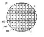
以下、本発明の具体例を実施例及び図面を用いて詳細に説明する。まず、実施例1及び2に共通する液晶表示機能付き遊戯装置の液晶表示部の構成について図1〜図3を用いて説明する。なお、図1は本発明の実施例1における液晶表示機能付き遊戯装置の液晶表示部と回転表示体を示す斜視図、図2は図1の液晶表示部の透視部位置における縦断面図、図3は本発明の実施例1におけるカラーフィルター層の一部拡大正面図である。 Hereinafter, specific examples of the present invention will be described in detail with reference to examples and drawings. First, the structure of the liquid crystal display part of the game apparatus with a liquid crystal display function common to Examples 1 and 2 will be described with reference to FIGS. 1 is a perspective view showing a liquid crystal display unit and a rotating display body of a game apparatus with a liquid crystal display function according to a first embodiment of the present invention, and FIG. 2 is a longitudinal sectional view of the liquid crystal display unit in FIG. 3 is a partially enlarged front view of the color filter layer in Example 1 of the present invention.
図1及び図2において、遊戯装置であるスロットマシン本体は省略するが、スロットマシンの前面に設けた液晶表示部10は、液晶表示パネル11と、その背面側に配置されたプリズムシート12及び拡散シート13とを積層してなる光学シート14と、この光学シート14の背面側に配置されたバックライト15と、これらを積層して一体化するための枠体16及びケース17とから構成されている。 In FIG. 1 and FIG. 2, the slot machine main body which is an amusement device is omitted, but the liquid
バックライト15は、背面に反射シート18が配置された透明な材料からなる導光板19と、この導光板19の端面に対向して配置された蛍光灯からなる光源20とから構成されている。この導光板19自体の背面には乱反射のためのドットパターン(図示せず)が形成されており、反射シート18と併せて導光板19の側方から入射した光源20からの光を前方に効果的に反射させるようになっている。この反射シート18によって前方に反射された光は、光学シート14において、まず拡散シート13により全面に亘って均一な光量とされ、次にプリズムシート12により液晶表示パネル11に向かう指向性を有するものとされている。 The
一方、液晶表示パネル11の裏側には3個のドラム状の回転表示体22、22’,22”が配されている。これら回転表示体22〜22”はその周面に種々の絵柄、数字からなるシンボルマークが施され、且つそれぞれが独立に回転できるようになっている。これらシンボルマークは液晶表示部10に形成された3個の透視部23、23’、23”を介して液晶表示部10の前方から見えるようになっている。 On the other hand, on the back side of the liquid
透視部23〜23”は、導光板19の前方に位置する光学シート14に形成した光学シート開口部24と、導光板19の後方に位置する反射シート18に形成した反射シート開口部25と、反射シート開口部25に対応する導光板19の背面にドットパターンを施さない面26と、ケース17に形成したケース開口部27と、液晶表示パネルに形成された表示用透視部(図示せず)とからなっている。そして、これら透視部23〜23”、25、27の形状は矩形である。 The see-through
また、液晶表示パネル11は、ドライバーICからなる駆動回路(図示せず)を有し、この駆動回路により種々の表示を行うと共に、表示用透視部の透明の度合いを制御するようになっている。 The liquid
図3に、液晶表示パネル11の表面の一部を拡大して示す。液晶表示パネルには、カラーフィルター層30が設けられている。カラーフィルター層30は画素毎に赤(R)、緑(G)、青(B)の色フィルター30R、30G、30Bがストライブ配列されて形成され、カラーフィルター層を厚み方向で捉えた場合に、カラーフィルター部分という表現で表す。そして、R、G、Bの3つのサブピクセルで1つの画素を構成すると共に、画像をくっきりさせるためサブピクセル毎に遮光性のブラックマトリックス31で囲んでいる。 FIG. 3 shows an enlarged part of the surface of the liquid
以下において、実施例1に係る液晶表示機能付き遊戯装置の液晶表示部10のカラーフィルター部分の構成を図4及び図5を用いて詳細に説明する。実施例1における液晶表示機能付き遊戯装置の液晶表示部10は、以上のような構成の液晶表示パネル11において、液晶透視部に相当する部分を除く範囲のカラーフィルター部分を、透視部以外の第2部分32とし、液晶透視部に相当する部分を“透視部に位置する第1部分”34として形成し、透視部に位置するカラーフィルター部分34を薄くしたものである。 Hereinafter, the configuration of the color filter portion of the liquid
実施例1に係る液晶表示パネル11の透視部以外の第2部分32の一部拡大断面図を図4に示す。この液晶表示パネル11は、所定の間隔を置いて配された一対のガラス基板35、36と、一方のガラス基板35の内面側に配された透視部以外の第2部分32と、透視部以外の第2部分32と他方のガラス基板36とによって形成された間隙に封じ込まれた液晶層37とから形成されている。そして、ガラス基板35、36の内面には駆動回路によって駆動される透明な共通電極(図示省略)及び画素電極39が設けられている。また、ガラス基板35、36の表面には偏光板40、41が設けられている。なお、符号31の部分は、ブラックマトリックス(図3参照)である。 FIG. 4 shows a partially enlarged cross-sectional view of the
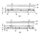
また、実施例1に係る液晶表示パネル11の透視部に位置する第1部分34の一部拡大断面を図5(a)及び図5(b)に示す。なお、図5(a)は透視部に位置する第1部分34の表面に透明部材42を配置したものを示し、図5(b)は透視部に位置する第1部分34と一方のガラス基板35との間に透明部材42を設けたものを示し、いずれも図4に記載のものと同一の構成部分については同じ参照符号を付与してその詳細な説明は省略する。 Moreover, the partially expanded cross section of the
この透視部に位置する第1部分34は、ガラス基板35の内面側に配置されており、しかも、このカラーフィルター層の厚さL2は前記透視部以外の第2部分32の厚さL1よりも薄く形成されている。そこで、その厚さの差を補うために、前記透視部に位置する第1部分34は、透明部材42を設けることにより、全体に亘り前記透視部以外の第2部分32と同じ厚さL1となるようになされている。 The
透視部以外の第2部分32と透視部に位置する第1部分34の具体的な厚さの一例は次のとおりである。例えば、透視部以外の第2部分32の厚さL1は良好なカラー表示を行なうために、通常使用されている範囲である1.2μm〜2.2μmの範囲内で全面が均一となるように設定されている。一方、透視部に位置する第1部分34の厚さL2は、カラー表示が一定以上の鮮明さを維持してなされると同時に、透光状態にしたときに高速で回転する回転表示体22〜22”のシンボルマークの認識が阻害されない程度の厚さとして、透視部以外のカラーフィルター部分の厚さの約半分程度、約0.6〜1.2μmに設定されている。 An example of specific thicknesses of the
このような実施例1の構成による液晶表示機能付き遊戯装置は、電源を投入したゲーム開始前では液晶表記部10がバックライト15による背面からの照明と駆動回路の駆動により液晶透視部も含めて全面的な表示を行なうことができる。この表示としては、変化する装飾模様、ゲーム方法の説明等をすることができ、液晶透視部においてもその透視部に位置する第1部分34によってカラー表示がなされる。 In the game apparatus with a liquid crystal display function having the structure of the first embodiment, the liquid
その後、遊戯者がコインを投入してゲームを開始すると、液晶表示パネル11の透視部23〜23”に相当する液晶が駆動回路によって透明になされ、透視部23〜23”が形成される。この透視部23〜23”は、既に開口が形成されている光学シート開口部24、反射シート開口部25、ケース開口部27と共に形成されて、液晶表示部10の前面から回転表示体22〜22”のシンボルマークが見えるようにしている。 Thereafter, when the player inserts coins and starts the game, the liquid crystal corresponding to the see-through
次に、遊戯者は遊戯装置を操作して回転表示体22〜22”を回転させる。この操作によって遊戯者は、透視部23〜23”から高速で変化する回転表示体22〜22”のシンボルマークを監視し、その内の1つについてストップ操作を行なういわゆる目押し操作を行って回転を停止させる。以下順に他の回転表示体22〜22”を停止させ、それぞれの透視部23〜23”に所望のシンボルマークが表示されることを目標に操作してゲームを楽しむことができる。 Next, the player operates the game apparatus to rotate the
従って、上述した本発明の実施例1においては、液晶表示パネル11に設けられた透視部に位置する第1部分34はカラーフィルター部分の厚さが透視部以外の第2部分32に比べて薄いので透光性が良好となり、しかも駆動部によって透視部に位置する第1部分34に対応する液晶表示パネル11の表示を透視部以外の第2部分32に相当する液晶表示パネル11の表示とを異ならせて駆動することができる。 Therefore, in the first embodiment of the present invention described above, the
そのため、ゲーム開始前には透視部に位置するカラーフィルター領域34に相当する液晶表示パネル11をも含めて全面に亘ってゲーム方法、装飾等の表示を行ない、ゲーム開始後には、透視部に位置する第1部分34に対応する液晶表示パネル11を透明として透視部23〜23”を形成し、後方に配置された回転表示体22〜22”が液晶表示パネル11の前方から明るい状態で見えるようになる。 Therefore, the game method, decoration, and the like are displayed over the entire surface including the liquid
従って、本実施例1の液晶表示機能付き遊戯装置においては、遊戯者はゲーム開始前には、液晶表示パネル11の全面に表示されたカラー表示によるゲーム方法を認識し易く、またカラー装飾等を楽しむことができる。そして、ゲーム開始後には、カラーフィルター層の影響の少ない透視部23〜23”をとおして回転表示体22〜22”のシンボルマークを確実に確認し、ゲームを楽しむことができるようになる。 Therefore, in the game apparatus with a liquid crystal display function according to the first embodiment, the player can easily recognize the game method based on the color display displayed on the entire surface of the liquid
また、本実施例1の液晶表示機能付き遊戯装置は、透視部に位置する第1部分34の透光性の増加が層を薄くすることにより達成でき、しかも、透視部に位置する第1部分34を透視部以外の第2部分32に比し薄くした分だけ透明部材42を設けてカラーフィルター層30の全体が同じ厚さとなるようしたので、カラーフィルター層30、ガラス基板35、偏光板40等と共に一体に形成できるという効果を有すると共に、透視部に位置する第1部分34に対して特別な補償を行う必要がなく、透視部に位置する第1部分と透視部以外の第2部分で表示の異なる液晶表示をすることができるという効果を奏する。加えて、透視部以外の第2部分32と透視部に位置する第1部分34との境界には段差が生じないため、ギャップ制御が容易で、液晶表示パネル全体で表示を行なう際に、境界部分によって視覚的に悪影響を与えることが少なくなる。 In addition, in the game device with a liquid crystal display function of the first embodiment, the increase in translucency of the
実施例2は、上述のような液晶表示機能付き遊戯装置の液晶表示部10の液晶表示パネル11において、透視部に位置する第1部分34に孔45を設けたものである。この実施例2の透視部に位置する第1部分34の一部拡大断面図を図6に示す。なお、実施例2においては透視部以外の第2部分32の構成は実施例1の図4に示したものと同一であり、また、図6に記載の透視部に位置する第1部分34については、図4に記載のものと同一の構成要素には同じ参照符号を付与することとしてその詳細な説明は省略する。実施例2においては、透視部に位置する第1部分34の厚さは透視部以外の第2部分32の厚さL1と同一であるが、各サブピクセル単位でカラーフィルター層に孔45が設けられてカラーフィルター層の占める面積が小さくなされており、この孔45には透明部材42が充填されている。 In the liquid
このような実施例2の構成による液晶表示機能付き遊戯装置によれば、液晶表示パネル11に設けられた透視部に位置する第1部分34は、サブピクセル単位でカラーフィルター層の占有面積を低減して、透光性が透視部以外の第2部分32よりも良好になるようにしたので、前述した実施例1の場合と同様に、遊戯者はゲーム開始前には液晶表示パネル11の全面に表示されたカラー表示によるゲーム方法を認識し易く、またカラー装飾等を楽しむことができ、ゲーム開始後には透視部23〜23”をとおして高速に回転する回転表示体22〜22”のシンボルマークを確実に確認しながらゲームを楽しむことができるという両方の機能を達成できるようになる。 According to the game apparatus with a liquid crystal display function having the configuration of the second embodiment, the
また、上記実施例2においては、透視部に位置する第1部分34の透光性の増大が、単にサブピクセルにカラーフィルターに孔45を形成し、この孔内に透明部材を充填するだけで達成され、しかも、透視部以外の第2部分32と透視部に位置する第1部分34との間の厚さに差異が生じないため、ギャップ制御が容易で、透視部に位置する第1部分34に対して駆動する際に特別な補償を行う必要がなく、液晶表示パネル11全体として共通の駆動回路でもって駆動することができるという効果を奏する。 Further, in the second embodiment, the increase in the translucency of the
実施例3は、上述のような液晶表示機能付き遊戯装置の液晶表示部10の液晶表示パネル11において、透視部に位置するカラーフィル第1部分ター領域34のカラー表示を強調するために、カラーフィルターの厚さL3を透視部以外のカラーフィルターの厚さL1よりも厚くしたものである。この実施例3の透視部に位置する第1部分34の一部拡大断面図を図7に示す。なお、実施例3においては透視部以外の第2部分32の構成は実施例1の図4に示したものと同一であり、また、図7に記載の透視部に位置する第1部分34については、図4に記載のものと同一の構成要素には同じ参照符号を付与することとしてその詳細な説明は省略する。 In the third embodiment, in the liquid
実施例3においては、第1部分34の厚さL3は、透視部以外の第2部分32の厚さL1により変化するが、L3>L1となる条件の基で、L3=1.5μm〜2.2μmの範囲で選択される。 In the third embodiment, the thickness L3 of the
この場合、透視部以外の第2部分32と透視部に位置する第1部分34の間に段差が生じるが、透視部以外の第2部分32に、実施例1と同様の方法で、透明部材42を配置することによって厚さが透視部に位置するカラーフィルター部分の厚さと同じL3となるようにしてもよい。 In this case, a step is generated between the
このような実施例3の構成による液晶表示機能付き遊戯装置によれば、液晶表示パネル11に設けられた透視部に位置する第1部分34は、サブピクセル単位でカラーフィルター部分の厚さが透視部以外の第2部分32に比べて厚くなるようにしたので、この部分では色の濃い、鮮やかな色調のカラー表示を行うことができるようになる。 According to the game apparatus with a liquid crystal display function having the configuration of the third embodiment, the
なお、上述した実施例1〜3にあっては、サブピクセルを囲んでブラックマトリックス31を設けたものを示したが、このようなブラックマトリックス31を設けないでカラーフィルター層30を形成してもよい。 In the first to third embodiments described above, the
10 液晶表示部
11 液晶表示パネル
14 光学シート14
15 バックライト15
18 反射シート
19 導光板19
20 光源20
22〜22” 回転表示体
23〜23” 透視部
24 光学シート開口部
25 反射シート開口部
27 ケース開口部
30 カラーフィルター
31 ブラックマトリックス
32 透視部以外の第2部分
34 透視部に位置する第1部分
35、36 ガラス基板
37 液晶層
38 共通電極
39 画素電極
40、41 偏光板
42 透明部材
45、45’ 孔DESCRIPTION OF
15
18
20
22 to 22 ″ Rotating
Claims (2)
Translated fromJapaneseたバックライトと、前記バックライトの後方に配された回転表示体と、前記液晶表示パネ
ルに設けられ、該液晶表示パネルの前方から前記回転表示体を見えるようにするための透
視部を有する液晶表示機能付き遊戯装置において、
前記カラーフィルター層は、前記透視部に位置する第1部分のカラーフィルター層と透
視部以外の第2部分のカラーフィルター層の透光性が異なっており、
前記透視部に位置する前記第1部分のカラーフィルター層は、前記透視部以外の前記第2部分のカラーフィルター層と同じ厚さであり、
前記透視部に位置する前記第1部分は、各サブピクセル単位で前記カラーフィルター層に孔が設けられて前記カラーフィルター層の占める面積が小さくなされており、前記孔には透明部材が充填され、
前記サブピクセル毎にブラックマトリクスで囲まれており、
前記透視部に位置する前記ブラックマトリクス上の前記第1部分どうしの間にも前記透明部材が配置されていることを特徴とする液晶表示機能付き遊戯装置。A liquid crystal display panel having a color filter layer, a backlight provided on the back of the liquid crystal display panel, a rotating display disposed behind the backlight, and a liquid crystal display panel provided on the liquid crystal display panel. In the game apparatus with a liquid crystal display function having a see-through portion for making the rotating display body visible from the front of
The color filter layer is different in translucency between the color filter layer of the first part located in the fluoroscopic part and the color filter layer of the second part other than the fluoroscopic part,
A color filter layer ofthe first portion positioned in the see-through portion has the same thickness as the color filter layer ofthe second portion other than the see-through portion,
The first portion located in the see-through portion has a hole formed in the color filter layer in each subpixel unit so that the area occupied by the color filter layer is reduced, and the hole is filled with a transparent member,
Each subpixel is surrounded by a black matrix,
A game apparatus with a liquid crystal display function,wherein the transparent member is disposed between the first portions on the black matrix located in the see-through portion .
前記透視部は前記光学シートに形成された開口部を含んでなることを特徴とする請求項1に記載の液晶表示機能付き遊戯装置。An optical sheet formed by laminating a prism sheet and a diffusion sheet is disposed on the back side of the liquid crystal panel,
The game device with a liquid crystal display function according to claim 1,wherein the see-through portion includes an opening formed in the optical sheet .
Priority Applications (1)
| Application Number | Priority Date | Filing Date | Title |
|---|---|---|---|
| JP2004066809AJP4604518B2 (en) | 2004-03-10 | 2004-03-10 | Game equipment with LCD display function |
Applications Claiming Priority (1)
| Application Number | Priority Date | Filing Date | Title |
|---|---|---|---|
| JP2004066809AJP4604518B2 (en) | 2004-03-10 | 2004-03-10 | Game equipment with LCD display function |
Publications (2)
| Publication Number | Publication Date |
|---|---|
| JP2005253561A JP2005253561A (en) | 2005-09-22 |
| JP4604518B2true JP4604518B2 (en) | 2011-01-05 |
Family
ID=35079887
Family Applications (1)
| Application Number | Title | Priority Date | Filing Date |
|---|---|---|---|
| JP2004066809AExpired - Fee RelatedJP4604518B2 (en) | 2004-03-10 | 2004-03-10 | Game equipment with LCD display function |
Country Status (1)
| Country | Link |
|---|---|
| JP (1) | JP4604518B2 (en) |
Families Citing this family (31)
| Publication number | Priority date | Publication date | Assignee | Title |
|---|---|---|---|---|
| US8715058B2 (en) | 2002-08-06 | 2014-05-06 | Igt | Reel and video combination machine |
| US7841944B2 (en) | 2002-08-06 | 2010-11-30 | Igt | Gaming device having a three dimensional display device |
| US7857700B2 (en) | 2003-09-12 | 2010-12-28 | Igt | Three-dimensional autostereoscopic image display for a gaming apparatus |
| US7309284B2 (en) | 2004-01-12 | 2007-12-18 | Igt | Method for using a light valve to reduce the visibility of an object within a gaming apparatus |
| US7488252B2 (en) | 2004-11-05 | 2009-02-10 | Igt | Single source visual image display distribution on a gaming machine |
| US7878910B2 (en) | 2005-09-13 | 2011-02-01 | Igt | Gaming machine with scanning 3-D display system |
| US8968077B2 (en) | 2006-04-13 | 2015-03-03 | Idt | Methods and systems for interfacing with a third-party application |
| US8784196B2 (en) | 2006-04-13 | 2014-07-22 | Igt | Remote content management and resource sharing on a gaming machine and method of implementing same |
| US10026255B2 (en) | 2006-04-13 | 2018-07-17 | Igt | Presentation of remotely-hosted and locally rendered content for gaming systems |
| US9028329B2 (en) | 2006-04-13 | 2015-05-12 | Igt | Integrating remotely-hosted and locally rendered content on a gaming device |
| US8777737B2 (en) | 2006-04-13 | 2014-07-15 | Igt | Method and apparatus for integrating remotely-hosted and locally rendered content on a gaming device |
| US8992304B2 (en) | 2006-04-13 | 2015-03-31 | Igt | Methods and systems for tracking an event of an externally controlled interface |
| US8512139B2 (en) | 2006-04-13 | 2013-08-20 | Igt | Multi-layer display 3D server based portals |
| US20090156303A1 (en) | 2006-11-10 | 2009-06-18 | Igt | Bonusing Architectures in a Gaming Environment |
| US9311774B2 (en) | 2006-11-10 | 2016-04-12 | Igt | Gaming machine with externally controlled content display |
| AU2007323962B2 (en) | 2006-11-13 | 2012-07-12 | Igt | Single plane spanning mode across independently driven displays |
| US8210922B2 (en) | 2006-11-13 | 2012-07-03 | Igt | Separable game graphics on a gaming machine |
| US8360847B2 (en) | 2006-11-13 | 2013-01-29 | Igt | Multimedia emulation of physical reel hardware in processor-based gaming machines |
| US8357033B2 (en) | 2006-11-13 | 2013-01-22 | Igt | Realistic video reels |
| US8192281B2 (en) | 2006-11-13 | 2012-06-05 | Igt | Simulated reel imperfections |
| US8727855B2 (en) | 2006-11-13 | 2014-05-20 | Igt | Three-dimensional paylines for gaming machines |
| US8142273B2 (en) | 2006-11-13 | 2012-03-27 | Igt | Presentation of wheels on gaming machines having multi-layer displays |
| US8616953B2 (en) | 2007-08-31 | 2013-12-31 | Igt | Reel symbol resizing for reel based gaming machines |
| US8115700B2 (en) | 2007-09-20 | 2012-02-14 | Igt | Auto-blanking screen for devices having multi-layer displays |
| US8012010B2 (en) | 2007-09-21 | 2011-09-06 | Igt | Reel blur for gaming machines having simulated rotating reels |
| US8758144B2 (en) | 2007-10-23 | 2014-06-24 | Igt | Separable backlighting system |
| US8425316B2 (en) | 2010-08-03 | 2013-04-23 | Igt | Methods and systems for improving play of a bonus game on a gaming machine and improving security within a gaming establishment |
| US8298081B1 (en) | 2011-06-16 | 2012-10-30 | Igt | Gaming system, gaming device and method for providing multiple display event indicators |
| US9524609B2 (en) | 2011-09-30 | 2016-12-20 | Igt | Gaming system, gaming device and method for utilizing mobile devices at a gaming establishment |
| US9466173B2 (en) | 2011-09-30 | 2016-10-11 | Igt | System and method for remote rendering of content on an electronic gaming machine |
| US8605114B2 (en) | 2012-02-17 | 2013-12-10 | Igt | Gaming system having reduced appearance of parallax artifacts on display devices including multiple display screens |
Family Cites Families (4)
| Publication number | Priority date | Publication date | Assignee | Title |
|---|---|---|---|---|
| JP3204822B2 (en)* | 1993-11-09 | 2001-09-04 | 株式会社オリンピア | Slot machine |
| JP2004008705A (en)* | 2002-06-11 | 2004-01-15 | Aruze Corp | Gaming machines and display devices for gaming machines |
| JP4562996B2 (en)* | 2003-05-09 | 2010-10-13 | 株式会社 日立ディスプレイズ | Display device |
| JP4474125B2 (en)* | 2003-07-14 | 2010-06-02 | 株式会社 日立ディスプレイズ | Display device |
- 2004
- 2004-03-10JPJP2004066809Apatent/JP4604518B2/ennot_activeExpired - Fee Related
Also Published As
| Publication number | Publication date |
|---|---|
| JP2005253561A (en) | 2005-09-22 |
Similar Documents
| Publication | Publication Date | Title |
|---|---|---|
| JP4604518B2 (en) | Game equipment with LCD display function | |
| CN102136169B (en) | Gaming machine | |
| KR101046224B1 (en) | Display device | |
| US6926606B2 (en) | Gaming machine | |
| JP4025463B2 (en) | Slot machine | |
| JP3993347B2 (en) | Slot machine | |
| JP4248831B2 (en) | Game display device | |
| US8502936B2 (en) | System, apparatus and methods for improved transmissivity of LCD panel | |
| JP2005274907A (en) | Liquid crystal display | |
| JP2006081820A (en) | Slot machine | |
| US8711059B2 (en) | Display apparatus | |
| JP2008178519A (en) | Game machine | |
| JP2004089707A (en) | Indicator for game machine and game machine | |
| US20100190552A1 (en) | Lcd display for gaming device with increased apparent brightness | |
| KR101153892B1 (en) | Display device with sub backlight | |
| JP4456831B2 (en) | Slot machine type gaming machine | |
| JP5160635B2 (en) | Liquid crystal display unit, liquid crystal display unit control method, and game apparatus | |
| JP2015536017A (en) | Backlight unit, liquid crystal display device including the same, and game machine | |
| ZA200609083B (en) | Gaming machine | |
| JP2005160759A (en) | Display device and game machine | |
| JP2009101020A (en) | Game machine | |
| KR20110045773A (en) | Display device | |
| JP2007160018A (en) | Game display device | |
| JP5593561B2 (en) | Image display device and game machine including image display device | |
| EP2770366B1 (en) | Backlight unit, and liquid crystal display device and game console including same |
Legal Events
| Date | Code | Title | Description |
|---|---|---|---|
| RD01 | Notification of change of attorney | Free format text:JAPANESE INTERMEDIATE CODE: A7421 Effective date:20051227 | |
| A621 | Written request for application examination | Free format text:JAPANESE INTERMEDIATE CODE: A621 Effective date:20070228 | |
| A711 | Notification of change in applicant | Free format text:JAPANESE INTERMEDIATE CODE: A711 Effective date:20070228 | |
| A977 | Report on retrieval | Free format text:JAPANESE INTERMEDIATE CODE: A971007 Effective date:20100224 | |
| A131 | Notification of reasons for refusal | Free format text:JAPANESE INTERMEDIATE CODE: A131 Effective date:20100316 | |
| RD03 | Notification of appointment of power of attorney | Free format text:JAPANESE INTERMEDIATE CODE: A7423 Effective date:20100402 | |
| A521 | Request for written amendment filed | Free format text:JAPANESE INTERMEDIATE CODE: A821 Effective date:20100405 | |
| A521 | Request for written amendment filed | Free format text:JAPANESE INTERMEDIATE CODE: A523 Effective date:20100514 | |
| A521 | Request for written amendment filed | Free format text:JAPANESE INTERMEDIATE CODE: A821 Effective date:20100517 | |
| A131 | Notification of reasons for refusal | Free format text:JAPANESE INTERMEDIATE CODE: A131 Effective date:20100608 | |
| A521 | Request for written amendment filed | Free format text:JAPANESE INTERMEDIATE CODE: A523 Effective date:20100809 | |
| A521 | Request for written amendment filed | Free format text:JAPANESE INTERMEDIATE CODE: A821 Effective date:20100810 | |
| TRDD | Decision of grant or rejection written | ||
| A01 | Written decision to grant a patent or to grant a registration (utility model) | Free format text:JAPANESE INTERMEDIATE CODE: A01 Effective date:20100907 | |
| A01 | Written decision to grant a patent or to grant a registration (utility model) | Free format text:JAPANESE INTERMEDIATE CODE: A01 | |
| A61 | First payment of annual fees (during grant procedure) | Free format text:JAPANESE INTERMEDIATE CODE: A61 Effective date:20100920 | |
| R150 | Certificate of patent or registration of utility model | Free format text:JAPANESE INTERMEDIATE CODE: R150 | |
| FPAY | Renewal fee payment (event date is renewal date of database) | Free format text:PAYMENT UNTIL: 20131015 Year of fee payment:3 | |
| LAPS | Cancellation because of no payment of annual fees |