JP4604234B2 - Apparatus and method for increasing the resolution of an infrared touch system - Google Patents
Apparatus and method for increasing the resolution of an infrared touch systemDownload PDFInfo
- Publication number
- JP4604234B2 JP4604234B2JP2001541919AJP2001541919AJP4604234B2JP 4604234 B2JP4604234 B2JP 4604234B2JP 2001541919 AJP2001541919 AJP 2001541919AJP 2001541919 AJP2001541919 AJP 2001541919AJP 4604234 B2JP4604234 B2JP 4604234B2
- Authority
- JP
- Japan
- Prior art keywords
- infrared
- touch
- transmitter
- transmitters
- receivers
- Prior art date
- Legal status (The legal status is an assumption and is not a legal conclusion. Google has not performed a legal analysis and makes no representation as to the accuracy of the status listed.)
- Expired - Fee Related
Links
Images


Classifications
- G—PHYSICS
- G06—COMPUTING OR CALCULATING; COUNTING
- G06F—ELECTRIC DIGITAL DATA PROCESSING
- G06F3/00—Input arrangements for transferring data to be processed into a form capable of being handled by the computer; Output arrangements for transferring data from processing unit to output unit, e.g. interface arrangements
- G06F3/01—Input arrangements or combined input and output arrangements for interaction between user and computer
- G06F3/03—Arrangements for converting the position or the displacement of a member into a coded form
- G06F3/041—Digitisers, e.g. for touch screens or touch pads, characterised by the transducing means
- G06F3/042—Digitisers, e.g. for touch screens or touch pads, characterised by the transducing means by opto-electronic means
- G06F3/0421—Digitisers, e.g. for touch screens or touch pads, characterised by the transducing means by opto-electronic means by interrupting or reflecting a light beam, e.g. optical touch-screen
Landscapes
- Engineering & Computer Science (AREA)
- General Engineering & Computer Science (AREA)
- Theoretical Computer Science (AREA)
- Human Computer Interaction (AREA)
- Physics & Mathematics (AREA)
- General Physics & Mathematics (AREA)
- Position Input By Displaying (AREA)
- Length Measuring Devices By Optical Means (AREA)
- Switches That Are Operated By Magnetic Or Electric Fields (AREA)
Abstract
Description
Translated fromJapanese【0001】
この発明は、全体として、赤外線(IR)利用可能なタッチシステム又はタッチスクリーンに関する。より詳しくは、本発明は、IRタッチシステムの分解能を高めるための創意に富んだシステム及び方法に関する。システム及び方法は、同軸上の及び同軸上にないIRトランスミッタ−レシーバの検出を用いて、スクリーン上のタッチ位置を決定するための、より高い分解能を提供する。本発明の方法の1つの実施の形態では、タッチ位置が、まず、大まかなタッチ位置を識別し、続いて、大まかな位置領域内でより厳密なタッチ位置を決めることにより決定される。タッチ位置の分解能の向上は、IRトランスミッタ−レシーバの密集度を上げる必要なく、あるいは、処理速度を上げる必要なく、本発明のシステムを用いて実現可能である。
【0002】
背景技術
タッチシステムは、日常において広く用いられるようになってきた。マネー・アクセス・センター(money access center),ロビー・ディレクトリ(lobby directory),ミュージアム及びエンターテインメント・キオスク及び自動車の位置決めシステムのディスプレイに用いられるタッチシステムに加えて、小型化されたタッチシステムがポケット型ダイアリや形成体における選択用の技術媒体となりつつある。赤外線タッチシステムがこれらの実用例に用いられ得る一方で、これらの又他の新たな市場にて利用されるように、IRタッチシステムを含むタッチシステムでのタッチ位置の決定は、迅速に,明確にまた精密に行なわれる必要がある。これは、特に、所望の動作又はシステムの選択を認識するためのユーザの手段として、比較的小さなポイント針又はポインタが利用され得る、ポケット型ダイアリについてのケースである。
【0003】
一般的に、タッチの位置は、典型的には発光ダイオード(“LED”)であるIRトランスミッタと、典型的にはフォトトランジスタ(“photo”)であるIRレシーバとを使用して認識される。先行技術のタッチスクリーンの例が、図1に示される。例えばLEDからなる、n個のIRトランスミッタ20(1)〜20(n)の組及び他のm個のIRトランスミッタ40(1)〜40(m)の組が、タッチスクリーン11の2つの隣接した縁部に沿って位置決めされている。n個のIRレシーバ30(1)〜30(n)の組及び他のm個のIRレシーバ50(1)〜50(m)の組が、各レシーバ30(i)及び50(i)が、それぞれ20(i)及び40(i)の対向するレシーバと同軸上に位置合わせされるように、タッチスクリーン11の反対側にある縁部に沿って位置決めされている。規定されるように、トランスミッタ20(i)及び40(i),レシーバ30(i)及び50(i)とは、n個のトランスミッタおよび各レシーバについて、i=1,2,3,i,i+1,...,n−1,nであり、また、m個のトランスミッタおよび各レシーバについて、i=1,2,3,i,i+1,...,m−1,mである場合に、各一連のトランスミッタ及びレシーバを意味している。
【0004】
従来のタッチシステムでは、トランスミッタがそれぞれ同軸上にレシーバと位置合わせされるので、スクリーンの外周部に沿って用いられるトランスミッタの数が、対向するスクリーンの縁部に沿って位置決めされるレシーバの数に等しい。図1に示されるように、典型的なタッチスクリーン11は、例えばx座標対20(1)及び30(1)であるx座標トランスミッタ−レシーバ対と、例えばy座標対40(3)及び50(3)であるy座標トランスミッタ−レシーバ対とのデカルト座標格子を作成する。したがって、検出パターンは、x及びy座標の直交格子である。
【0005】
タッチの位置は、x座標対及びy座標対を走査し、いずれのトランスミッタ−レシーバ対がIR光の妨害を示すかを識別する。走査プロセスは、各レシーバ30(i)及び50(i)の作動,各々に対向するトランスミッタ20(i)及び40(i)の作動すなわち発光,トランスミッタ20(i)及び40(i)のIR信号が同軸上の各レシーバ30(i)又は50(i)により受信されているかどうかの検出、および、各レシーバ30(i)及び50(i)の動作停止を伴う。このレシーバの作動,同軸上のトランスミッタの発光,レシーバの動作停止のプロセスは、全てのトランスミッタ−レシーバ対が走査されるまで、同軸上の各トランスミッタ‐レシーバ対について繰り返される。
【0006】
従来のタッチシステムについてのタッチ位置の正確さ及び精度は、スクリーン11の外周部に沿って位置決めされたトランスミッタおよびレシーバの密集度つまり数に依存するものである。図1に示されるような直交検出パターンに伴う問題は、タッチの直径95が、隣接したトランスミッタおよび隣接したレシーバの間隔よりも小さい場合に、ビームがクロスしていない領域にあるように、タッチが検出されない惧れがあることである。
【0007】
更に、タッチ位置の決定を行なうのに必要な時間は、トランスミッタおよびレシーバを作動させたり発光させたりするために、また、放たれたIR信号がレシーバによって受信されたかどうかを検出するために用いられるプロセッサの速度に依存するものである。明らかに、システムの処理能力が向上しなければ、タッチシステムに含まれるトランスミッタ−レシーバ対が多くなるにつれ、タッチ位置を識別するための時間が、トランスミッタ−レシーバ対の全ての組を走査するための時間とともに長くなる。
【0008】
IRトランスミッタおよびレシーバあるいはシステムの光電子部品が、IRタッチシステムの全コストの相当部分を占めているため、光電子デバイスの数の増加は、システムの全コストにおける著しい増大をもたらすことになる。同様に、プロセッサの電子部品が、IRタッチシステムのコストのまた別の相当部分を占めているため、タッチの認識に関した最大時間を確保するための処理速度の増大は、システムのコストにおける実質的な増大を引き起こすことになる。
【0009】
よく知られた従来の同軸上式のタッチシステムに加えて、アルパイン株式会社に所有される光学的な位置検出デバイスに関した、日本特許出願特開平11−232024号公報にて開示される1つのデバイスは、対向する発光ダイオードから放たれた光の範囲内での、2つ又はそれ以上の隣接したフォトトランジスタの検出に備えている。アルパインシステムの目的は、位置検出精度の可能な向上を見込めるLED及びフォトトランジスタの数,位置及び配置に関して、従来の制限をなくすることである。同軸上にないフォトトランジスタの使用を通じたLED出力の検出を明確に記載する一方で、アルパインシステムは、LED−フォトトランジスタ対を効率的に走査するためのいかなる方法をも記載しないつまり開示しないものとみえる。確かに、デバイス動作の記載は、全てのLEDを連続的にサイクルさせ、作動させられたLEDの各々について複数のフォトトランジスタを検出することを要するようにみえる。かかるデバイスは、LED毎の複数のフォトトランジスタを検出し、タッチスクリーンの外周部に沿って各LEDをサイクルさせることからもたらされる増加した情報を扱うために、著しく向上したコンピュータの処理能力を必要とすることになる。
【0010】
したがって、タッチの位置を明確に及び精密に識別すべく高められた分解能の能力を有し、相当数のIRトランスミッタ及びレシーバを必要とせず、また、トランスミッタおよびレシーバを制御し、走査動作に起因するデータを処理するために、著しく改良されたコンピュータ処理の要件を必要としない、IRタッチシステムが要される。かかるシステム及び方法は、現在では存在しないが、IRタッチスクリーンシステムの有用性及び能力を極めて大きくするものであろう。
【0011】
発明の概要
従来技術の欠点に鑑みて、本発明の目的は、タッチスクリーンのIRトランスミッタ又はIRレシーバの数を増やすことなく、明確で精密なタッチ位置の決定を行なう、高められた分解能の赤外線タッチシステム及び方法を提供することである。また、本発明の更なる目的は、高められたタッチ位置の分解能が、システムの分解能及び動作の速度を維持するために、大きな要求すなわちより速い速度の処理の要件を要しないことである。
【0012】
これらの又他の目的を実現するために、また、その趣旨を考慮して、本発明は、タッチスクリーンにおけるタッチの位置を決定するための、高められた分解能を有する赤外線タッチシステムを提供するもので、該赤外線タッチシステムは、タッチスクリーンの第1の縁部に沿って位置決めされる複数の第1の赤外線トランスミッタであり、各々が円錐形の赤外線光を制御可能に放射する第1の赤外線トランスミッタと、上記複数の第1のトランスミッタには正反対のタッチスクリーンの第2の縁部に沿って位置決めされる複数の第1の赤外線レシーバであり、各々が上記複数の第1の赤外線トランスミッタのうちの1つのトランスミッタと同軸上に位置合わせされ、他の複数の第1のトランスミッタの各々に対して同軸上にない複数の第1の赤外線レシーバと、タッチスクリーンの第1及び第2の縁部に垂直な第3の縁部に沿って位置決めされる複数の第2の赤外線トランスミッタであり、各々が円錐形の赤外線を制御可能に放射する第2の赤外線トランスミッタと、上記複数の第2のトランスミッタとは反対のタッチスクリーンの第4の縁部に沿って位置決めされる複数の第2の赤外線レシーバであり、各々が上記複数の第2のトランスミッタのうちの1つのトランスミッタと同軸上に位置合わせされ、他の複数の第2のトランスミッタの各々に対して同軸上にない複数の第2の赤外線レシーバと、複数の第1及び第2の赤外線トランスミッタの動作を制御し、複数の第1及び第2の赤外線レシーバの動作を制御し、赤外線トランスミッタおよびレシーバの同軸上のまた同軸上でない作動を用いて、タッチスクリーン上のタッチ位置を算出するためのプロセッサとを有している。
【0013】
本発明の更なる目的は、タッチスクリーンを有する赤外線タッチシステムを提供することであり、該赤外線タッチシステムは、タッチスクリーンの第1の縁部に沿って位置決めされる複数の第1の赤外線トランスミッタであり、各々が円錐形の赤外線光を制御可能に放射する第1の赤外線トランスミッタと、上記複数の第1のトランスミッタとは反対のタッチスクリーンの第2の縁部に沿って位置決めされる複数の第1の赤外線レシーバであり、各々が上記複数の第1の赤外線トランスミッタのうちの1つのトランスミッタと同軸上に位置合わせされ、他の複数の第1のトランスミッタの各々に対して同軸上になく、また、更に、上記複数の第1のトランスミッタの各々から放射された光による赤外線ビームが、少なくとも2つの第1のレシーバにより受信可能である複数の第1の赤外線レシーバと、タッチスクリーンの第3の縁部に沿って位置決めされた複数の第2の赤外線トランスミッタであり、各々が赤外線を制御可能に放射する第2の赤外線トランスミッタと、上記複数の第2のトランスミッタとは反対のタッチスクリーンの第4の縁部に沿って位置決めされる複数の第2の赤外線レシーバであり、各々が上記複数の第2のトランスミッタのうちの1つのトランスミッタと同軸上に位置合わせされ、他の複数の第2のトランスミッタの各々に対して同軸上になく、また、更に、第2のトランスミッタの各々から放射された光による赤外線ビームが、少なくとも2つの第2のレシーバにより受信可能である複数の第2の赤外線レシーバと、上記複数の第1及び第2の赤外線トランスミッタの各々及びそれに対向する上記複数の第1及び第2の赤外線レシーバを順次作動させるための第1のプロセッサと、タッチスクリーン上のタッチ位置を算出するための第2のプロセッサとを有しており、ここでは、上記第2のプロセッサが、作動させられたトランスミッタとレシーバとの間で妨害された赤外線ビームの識別に基づき、大まかなx座標のタッチ領域を識別し、作動させられたトランスミッタとレシーバとの間で妨害された赤外線ビームの識別に基づき、大まかなy座標のタッチ領域を識別し、識別された大まかなx座標及びy座標のタッチ領域から大まかなx座標及びy座標のタッチ領域を算出し、算出された大まかなタッチ領域を横切る赤外線ビームを有する同軸上にないトランスミッタ及びレシーバの対の規則正しい作動に基づき、x座標及びy座標のタッチ位置を精密に求める。
【0014】
本発明の更なる目的は、各トランスミッタが1つのレシーバに対して同軸上に位置合わせされるように、隣接した第1及び第2の縁部に沿って、複数の赤外線トランスミッタを有し、また、複数のトランスミッタに対向する隣接した第3及び第4の縁部に沿って、複数の赤外線レシーバを有するタッチシステムスクリーン上のタッチ位置を決定する方法を提供することであり、該方法は、各赤外線トランスミッタ及びそれに対向するレシーバの規則正しい同軸上の作動に基づき、大まかなタッチ位置を概算し、また、選択されたトランスミッタ及びレシーバの規則正しい同軸上でない作動に基づき、タッチ位置を精密に求めるステップを有している。
【0015】
本発明の更なる目的は、各トランスミッタが1つのレシーバに対して同軸上に位置合わせされるように、隣接した第1及び第2の縁部に沿って、複数の赤外線トランスミッタを有し、また、複数のトランスミッタに対向する隣接した第3及び第4の縁部に沿って、複数の赤外線レシーバを有するタッチシステムスクリーン上のタッチ位置を決定する方法を提供することであり、該方法は、各赤外線トランスミッタ及びそれに対向するレシーバの規則正しい同軸上の作動に基づき、大まかなタッチ位置を概算し、また、大まかなタッチ位置の概算値に基づき、同軸上にないトランスミッタおよびレシーバの対を選択し、更に、選択された同軸上にないトランスミッタ及びレシーバの対の規則正しい作動に基づき、タッチ位置を精密に求めるステップを有している。
【0016】
本発明の一層更なる目的は、各トランスミッタが1つのレシーバに対して同軸上に位置合わせされるように、x座標の縁部に沿ってx座標の複数の第1の赤外線トランスミッタを有するとともに、y座標の縁部に沿ってy座標の複数の第2の赤外線トランスミッタを有し、また、2つの縁部に沿って複数のトランスミッタに対向する複数の赤外線レシーバを有するタッチシステムスクリーン上のタッチ位置を決定する方法を提供することであり、該方法は、各赤外線トランスミッタ及びそれに対向するレシーバの規則正しい同軸上の作動に基づき、タッチスクリーン上での大まかなx座標及びy座標のタッチ位置を概算し、大まかなy座標のタッチ位置の概算値に基づき、同軸上にないトランスミッタおよびレシーバのx座標の対を選択し、選択された同軸上にないトランスミッタ及びレシーバのx座標の対の規則正しい作動に基づき、x座標のタッチ位置を精密に求め、大まかなx座標のタッチ位置の概算値に基づき、同軸上にないトランスミッタおよびレシーバのy座標の対を選択し、選択された同軸上にないトランスミッタ及びレシーバのy座標の対の規則正しい作動に基づき、y座標のタッチ位置を精密に求めるステップを有している。
【0017】
本発明のこれらの又他の様相は、図面および好ましい実施の形態の詳細な説明により後述される。前述した概説及び以下の詳細な説明の両方は例示的なもので、本発明の限定を意図するものでなく、また、そう認識されるべきでない。
【0018】
好ましい実施の形態の詳細な説明
本発明は、同軸上のまた同軸上でない検出の両方を利用して、タッチシステムスクリーン上のタッチの位置を決定するための分解能の向上をもたらす赤外線(“IR”)タッチシステムに関する。本発明は、また、IRトランスミッタ−レシーバ対の複数ステップの大まかな走査および選択されたトランスミッタ−レシーバ対の精密な操作とともに、同軸上のまた同軸上でない検出を利用して、タッチシステムスクリーン上のタッチの位置を決定するための方法に関する。本発明の方法は、また、任意のx又はyのタッチ位置に関して、タッチ位置を精密に求めるための代わりの軸のトランスミッタ−レシーバ対の選択が、そのタッチ位置に依存するという事実を利用するものである。換言すれば、x位置を精密に求めるためのy座標のトランスミッタ−レシーバ対の選択は、xの大まかな位置から決定可能であり、また、x座標のトランスミッタ−レシーバ対はyの大まかな位置から決定可能である。
【0019】
前述したように、従来のタッチシステムは、図1に示されるように、タッチスクリーン又はパネル11と、タッチスクリーン11の第1の縁部に沿って位置決めされる、典型的にはLEDであるn個のIRトランスミッタ20(1)〜20(n)の第1の組と、タッチスクリーン11の第2の縁部に沿って位置決めされる、典型的にはフォトトランジスタであるn個のIRレシーバ30(1)〜30(n)の第1の組と、タッチスクリーン11の第3の縁部に沿って位置決めされるm個のIRトランスミッタ40(1)〜40(m)の第2の組と、タッチスクリーン11の第4の縁部に沿って位置決めされるm個のIRレシーバ50(1)〜50(m)の第2の組とを有している。図1に示されるように、タッチスクリーン11上のタッチについての走査は、x方向における例えばレシーバ30(4)の作動を用い、同軸上で対向するトランスミッタ20(4)を発光させ、その後、トランスミッタ30(4)を動作停止すなわち消光させるステップを伴うものである。この順序は、x方向に沿ったトランスミッタ−レシーバ対20(i)−30(i)、および、y方向に沿ったトランスミッタ−レシーバ対40(i)−50(i)の各々について繰り返される。もし、タッチが、発光させられたx方向のトランスミッタ20(4)とそれに対向するレシーバ30(40)との間に存在すれば、トランスミッタ20(4)の光又はビームは妨害され、対向するレシーバ30(4)によって受信されず、その結果、そのx位置におけるタッチが指示される。同様に、もし、タッチが、発光させられたy方向のトランスミッタ40(m−1)とそれに対向するレシーバ50(m−1)との間に存在すれば、トランスミッタ40(m−1)の光又はビームは妨害され、そのy位置におけるタッチが指示される。
【0020】
タッチの座標は、妨害された第1及び最後のビームのx及びy座標の平均として、この同軸上での検出を用いて算出される。数式においては、x及びyのタッチ位置が次のように概算される。
xtouch=(xi+xi+1)/2
及び
ytouch=(yi+yi+1)/2
【0021】
従って、概算され得るタッチのx座標は、x1,x1+Δx/2,x2,x2+Δx/2,x3,...xi−Δx/2,xi,xi+Δx/2,xnである。ここで、nは、タッチスクリーン11の対向する縁部の一対に沿ったトランスミッタ−レシーバ対の数である。概算され得るy座標は、y座標の位置を用いることを除き、上記の場合と同様である。したがって、可能な座標のこのシーケンスから、タッチ位置を決定する分解能は、Δx/2,Δy/2である。
【0022】
トランスミッタ20(i),40(i)から放射されたIR光は円錐形をなすもので、単光束ビームではない。つまり、図2に示されるように、トランスミッタ20(3)から放射されたIR光は、隣接したレシーバ30(1),30(2),30(3),30(4)及び30(5)のグループにより受信され得る。図2の実施の形態は、トランスミッタ20(3)からのIR伝送を検出し得る5つの隣接したレシーバのグループを示しているが、IR光の円錐内にあるレシーバの数は、タッチスクリーンシステム10の特性により決まる。したがって、他の好ましい実施の形態では、IRトランスミッタ20(i)からのIR光を検出し得るレシーバ30(i)の数は、2つ,3つ,4つ若しくは5つ以上の隣接したユニットであってもよい。更に、レシーバ30(i)はトランスミッタ20(i)により放射されるIR光の円錐内にあるものであるが、円錐の縁部では、容易な検出を行なうのに、つまり、レシーバ30(i)が検出可能であるために十分なIR光が得られないかもしれない。
【0023】
したがって、異なるIRトランスミッタは、特定のトランスミッタの仕様に基づき、より広い若しくは狭い円錐のIR光を有してもよい。トランスミッタ及びレシーバのかかる特性の1つは、光電子ユニットの絞り感度である。更に、十分なパワーがIRトランスミッタにより生成され、また、IRレシーバが十分な感度を有する限り、トランスミッタとそれに対向するレシーバとの間隔は大きくなり、円錐の幅が広がるので、トランスミッタからのIR光を受信し得るレシーバの数は増え、対向する縁部はトランスミッタから遠くなる。
【0024】
図2に示される好ましい実施の形態について、レシーバ30(3)は、トランスミッタ20(3)と同軸上にあり、また、4つのトランスミッタ30(1),30(2),30(4),30(5)とは同軸上にない。図3に示されるような、作動させられたレシーバ30(4)の様子からすると、同軸上にないトランスミッタ20(3)からのIRビームはレシーバ30(4)によって検出可能である一方、同じレシーバ30(4)は、また、同軸上のトランスミッタ20(4)及び他の同軸上にないトランスミッタ20(2),20(5)及び20(6)を含む他のトランスミッタからのIR伝送を検出することも可能である。
【0025】
図4は、本発明の好ましい実施の形態に係る、より高い分解能の、可能な検出パターンを示す。図4に示されるように、各x及びyのトランスミッタ20(i),40(i)が作動させられた状態で、例えば、トランスミッタ20(3)を用いると、IR光の円錐が、同軸上の受信器30(3)により、また、それに加えて、その同軸上の受信器30(3)に隣接した同軸上にない2つのレシーバ30(2)及び30(4)により検出されるようになる。また、IR光の円錐は、同様に、同軸上にない次の2つのレシーバ30(1)及び30(5)によっても検出される。図4に示すこの好ましい実施の形態では、タッチ検出に用いられる同軸上にないトランスミッタ−レシーバ対が、
i=i±2
である。ここで、iは、同軸上のトランスミッタ及びレシーバの位置をあらわす。図4に示されるように、可能な検出座標つまりタッチスクリーン11上の検出パターンの数は、図1に示す従来システムのような同軸上の検出のみを用いた可能な検出座標の数よりも実質的に大きい。
【0026】
本発明に関した検出パターンは、従来の同軸上の検出よりも一層高い分解能を有するものの、両システムにおいて用いられる光電子デバイスの数は、同じ若しくは実質的に同じである。異なる視点から、本発明の別の好ましい実施の形態においては、タッチシステムに必要な光電子デバイスの数が、従来の同軸上の検出システムを用いて得られる分解能を上回るタッチ位置の分解能を犠牲にすることなく削減され得る。
【0027】
図4は、また、本発明が、隣接した光電子デバイス間の隔たりよりも小さい直径を有するタッチを感知することが可能であることを示している。このことは、前述したように、例えば細い針又はポインタなどのタッチの直径95が、隣接したトランスミッタ及び隣接したレシーバ間の隔たりよりも小さい場合に、タッチが検出されない可能性がある図1に示す従来の直交検出格子と比較されてもよい。
【0028】
図4に示す検出パターンは、本発明の実施の形態に係る、全ての可能な検出座標を示している。しかしながら、それは、全トランスミッタ及びレシーバを走査し、所望のシステムの応答時間を確保するには、タッチシステムプロセッサにとって効率的でないすなわち適していない可能性がある。本発明は、タッチの位置を突きとめる速度及び効率性が著しく向上させられるように、同軸上のまた同軸上でない走査の両方を用いて、光電子デバイスを走査する方法を提供する。
【0029】
本発明の方法の好ましい実施の形態では、タッチスクリーン11上のタッチの位置を迅速に識別し、精密に求めるべく、2ステップの走査動作が用いられる。第1のタッチスクリーン11の“大まかな”走査は、同軸上のトランスミッタ−レシーバ対のみ作動させ、検出することにより実行される。続いて、大まかな走査により識別された領域のみについての第2の“精密な”走査が、同軸上のまた同軸上にないトランスミッタ−レシーバ対の両方を用いて完了され得る。
【0030】
例として、図5には、この好ましい実施の形態の方法の第1の大まかな走査が示される。大まかな走査は、タッチスクリーン11の両縁部に沿って、レシーバ20(1)〜20(8)及び40(1)〜40(7)の各々を順次に作動させること、及び、それぞれ対応する同軸上のトランスミッタ30(1)〜30(8)及び50(1)〜50(7)の各々を発光させることを含んでいる。図5の好ましい実施の形態が、8つのx軸トランスミッタ−レシーバ対及び7つのy軸トランスミッタ−レシーバ対を用いて示されるが、他の好ましい実施の形態においては、それ以上の若しくはそれ未満のトランスミッタ−レシーバ対が、x又はy軸に沿って用いられてもよい。
【0031】
図5に示される本発明の方法のステップは、図1に示される従来のタッチシステム検出と同様である。図5に示されるタッチ100については、トランスミッタ20(5)及び40(4)からのIRビームが妨害され、そのため、対向する各レシーバ30(5)及び50(4)は、同軸上のIRビームを検出しなくなる。このように、トランスミッタ−レシーバ対20(4)−30(4)及び20(6)−30(6),40(3)−50(3)及び40(5)−50(5)により最終的に検出された同軸上のビームが、検出されたタッチを含む大まかな領域99を規定する。
【0032】
図5の実施の形態が、同軸上の検出格子のみを示している一方で、例えばより光速なプロセッサ及び電子部品を用いた他の好ましい実施の形態では、幾つかの同軸上にないトランスミッタ−レシーバ対が、タッチシステム検出の全体の速度及び効率性が劣化させられない限りは、大まかな走査を精練すべく利用され得ることに注目することが重要である。
【0033】
大まかな走査の完了及び大まかなタッチ領域99の識別後、大まかなタッチ領域99の第2の精密な走査が、同軸上の及び同軸上にないトランスミッタ−レシーバ対の両方を用いて実行され得る。精密な走査のために作動させられる同軸上にないトランスミッタ−レシーバ対は、1つの好ましい実施の形態では、そのIRビームが大まかなタッチ領域99を横切る対である。図6は、本発明のタッチシステム検出方法の好ましい実施の形態に関し、精密な走査に際して生成される検出パターンを示している。図6に示される検出パターンは、図4に示す実施の形態と同様に、トランスミッタ20(5)と同軸上にあるレシーバ30(5)を、また、同軸上のレシーバ30(5)の隣の2つのレシーバ30(4)及び30(6)を、更に、レシーバ30(4)及び30(6)にそれぞれ隣接した2つのレシーバ30(3)及び30(7)を作動させることにより生成される。他の好ましい実施の形態では、同軸上のレシーバの再作動が、プロセッサの検出要件を削減するために除去され得る。
【0034】
図6に示されるように、同軸上でない検出方法から取得される実質的に高められた分解能を強調すると、大まかな走査は2本の妨害されたビームをもたらし、他方、精密な走査は14本の妨害されたビームの検出をもたらした。この付加的なIRビームの妨害情報が、大まかなタッチ領域99内におけるより精密で明確なタッチ位置を提供すべく処理され得る。
【0035】
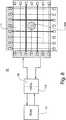
大まかなタッチ領域99を横切るIRビームを有するトランスミッタ−レシーバ対の選択は、トランスミッタ及びレシーバの絞り感度及びトランスミッタによりもたらされるIR円錐を含む光電子デバイスの特性に依存する。例えば、1つの実施の形態では、トランスミッタのIR円錐が、3つのレシーバにより検出可能であり、異なるトランスミッタ又はレシーバの隔たりを用いる別の好ましい実施の形態では、トランスミッタのIR円錐が、5つ又はそれ以上のレシーバによって検出可能である。特定のタッチシステム10及びタッチスクリーン11についての規模が与えられると、IR円錐を容易に検出し得るトランスミッタのIR円錐の特性およびIRレシーバの数が認識され、規定される。このように、精密な走査に用いられる検出可能なIRビームは、例えば図4及び図8における実施の形態において示されるように、特定のタッチシステム10に関して前以て決定されてもよい。1つの好ましい実施の形態では、可能なIRの同軸上でないビームの前決定が、大まかな同軸上の格子の位置選定の機能として表形式にされてもよい。表形式にされたデータは、プロセッサ読出し専用メモリ(“ROM”)17に保持され、大まかな同軸上のタッチ位置を識別する機能及びその後の機能としてシステムプロセッサ15によりアクセスされる。他の好ましい実施の形態では、システム処理が、テーブルルックアップやタッチ位置の計算と同じく、トランスミッタ及びレシーバの作動を制御する別々の作業に関して、図8にも示されるような複数のプロセッサ15及び16に分けられてもよい。
【0036】
本発明の方法は、各トランスミッタについての全てのレシーバを走査する必要なく、同軸上のまた同軸上でない検出を利用して、タッチ位置の高められた分解能を提供する。つまり、本発明の方法は、同軸上のトランスミッタ及びレシーバの対の第1の迅速な走査を提供し、それに引き続き、選択されたトランスミッタ−レシーバ対(そのIRビームが識別された大まかなタッチ領域を横切る)を作動させ走査する。図6の図示及び説明された好ましい実施の形態において、選択された対は、次のとおりである。トランスミッタ20(5)について、レシーバ30(3),30(4),30(5),30(6)及び30(7)が作動させられ検出される。また、トランスミッタ20(3)及び20(7)について、レシーバ30(5)が作動させられる。更に、トランスミッタ20(4)について、レシーバ30(4),30(5)及び30(6)が作動させられる。また、更に、トランスミッタ20(6)について、レシーバ30(4),30(5)及び30(6)が作動させられる。これらのトランスミッタ−レシーバ対は、大まかなタッチ領域99を横切るIRビームを有する。残りのトランスミッタ−レシーバ対は、作動させられず、検出されない。従って、第2の精密な走査に関して処理の要件が削減され、また、明確に且つより高い分解能で、タッチの位置100を決定するための時間が短縮される。図5の好ましい実施の形態に関して作動させられるy軸のトランスミッタ−レシーバ対は、前述した対と同様であり、ビームが大まかなタッチ領域99を横切る特定の対が選択される。
【0037】
IRタッチシステムにおけるタッチの存在及び位置を決定する本発明の方法についての別の好ましい実施の形態は、タッチのx又はy座標とタッチ位置を精密に求めるのに利用され得る代わりの軸のビームとの間における相互依存性を用いる。図7に示されるように、タッチ100は、(検出される最後の2本の同軸上のビームである)x軸のトランスミッタ20(1)と20(4)と間におけるx軸の大まかな位置と、A−A線に示されるようなタッチ100のy軸における概算された中心とを有する。これら概算されたタッチ位置の両方は、トランスミッタ及び対向するレシーバの第1の大まかな同軸上の走査から決定された。y軸のA−A線の算出結果は、前述したように、検出される最後の同軸上のIRビームの平均値である。図7に例示したタッチ100に関し、y軸のトランスミッタ−レシーバ対40(2)−50(2)及び40(5)−50(5)は、トランスミッタ−レシーバ対40(3)−50(3)と40(4)−50(4)との間における妨害されるビームの前の、検出される最後のビームである。
【0038】
図7に示されるように、タッチ100に関して精密なx座標の決定は、タッチ100の領域における検出される最後の2本の同軸上のビーム(図7の例に示されるようなx軸のトランスミッタ20(1)及び20(4))間を横切る、より詳細には、大まかなy軸のA−A線を横切る特定のx軸のトランスミッタ−レシーバ対を作動させることにより実現される。作動させられ得るx軸のトランスミッタ−レシーバ対は、y軸の大まかなタッチの位置選定の機能として決定されてもよい。つまり、大まかなyのタッチ位置は、作動させる代わりの軸(x軸)の対を選択するのに用いられてもよく、また、同様に、大まかなxのタッチ位置は、作動させる代わりの軸(y軸)の対を選択するのに用いられてもよい。IRビームが単に線状であることから、この相互依存性が生じる。更に詳しくは、ビームのあらゆる部分のx座標が、ビームの勾配(角度)及びレシーバにおけるIRビームのxの切片(x-intercept)からあらゆるy座標において簡単に算出され得る。数式では、
xi=x0+m*yi
である。ここで、xiは、yiでのビームのx座標である。mは、IRビームの勾配又は角度である。また、x0は、IRレシーバでのx座標である。あらゆるトランスミッタ−レシーバ対間におけるIRビームの勾配m又は角度は、タッチスクリーン11の縁部における各トランスミッタ−レシーバ対の位置が、付与されたタッチシステム10について知られ、また、前述したように、ビームが単にトランスミッタと各レシーバを接続する線状であることから、容易に算出され若しくは決定され得る。
【0039】
x軸と同様に、ビームのあらゆる部分のy座標は、ビームの勾配(角度)及びレシーバにおけるIRビームのyの切片から、あらゆるx座標にて容易に算出され得る。すなわち、数式では、
yi=y0+m*xi
である。ここで、yiは、xiでのビームのy座標である。また、mは、IRビームの勾配又は角度である。更に、y0は、IRレシーバにおけるy座標である。
【0040】
この相互依存性を考慮して、また、図7に図示されるように、y軸の大まかなタッチ位置が付与されると、好ましい実施の形態では、タッチ100のx座標を精密に求めるのに作動させられ検出され得る代わりの軸(x軸)のトランスミッタ−レシーバ対、及び、精密なx座標の算出結果が、A−A線のy座標の機能として決定され得る。例えば図7に示す例では、タッチのx座標の精密な算出結果が、概算されたy軸のA−A線におけるトランスミッタ−レシーバ対20(3)−30(1)及び20(8)−30(4)についての最後の妨害されないビームの平均値を用いることができる。A−A線でのビーム20(3)−30(1)及び20(8)−30(4)のx座標は、上記のx軸の式から算出されてもよい。同様に、精密なx軸の算出結果は、A−A線でのIR光電子対20(2)−30(2)及び20(4)−30(3)に関した、最後の妨害されたIRビームの平均値を用いることができる。他の好ましい実施の形態においては、精密なx座標が、前述した“最後の、妨害されない”平均値と“最後の、妨害される”平均値の平均値として算出されてもよい。
【0041】
別の好ましい実施の形態では、既知のトランスミッタ−レシーバビームのx座標が、より多くの複雑なプロセッサ15を必要とすることになる浮動小数点計算を用いる代わりに、選択された大まかなy軸位置すなわち座標の機能として前以て決定され、大まかなy軸座標の機能として、データテーブルとして格納されてもよい。図8の概略図に示されるように、表形式にされたデータは、プロセッサROM17に確保され、大まかなx軸及びy軸のタッチ位置を識別した後に、タッチシステムプロセッサ15によりアクセスされてもよい。
【0042】
図7に示されるような代わりの軸の間にある前述した相互依存性が、x座標の算出に焦点を絞る一方、y軸は、同様に、y軸のトランスミッタ−レシーバ対及びタッチスクリーン11を横切るように生成されるIRビームを用いて、精密に求められ得る。
【0043】
本発明は例示した実施の形態に関連して説明されてきたが、これに限定されることはない。例えば、前述したように、代わりの軸のトランスミッタ−レシーバ対の算出および決定は、任意のトランスミッタビームの特性についての三角測量(triangulation)の式の計算により、若しくは、数式の前計算から展開れたテーブルルックアップによって実現されてもよい。従って、本発明の要旨を逸脱しない範囲において、種々の改良及び設計上の変更が可能であることは言うまでもない。
【図面の簡単な説明】
【図1】 従来のタッチスクリーンシステムを示す平面図である。
【図2】 複数のIRレシーバへ伝送される例えばIRトランスミッタの円錐光をあらわす本発明のタッチシステムを示す平面図である。
【図3】 複数のIRトランスミッタからの光を受信する単一のIRレシーバの一例をあらわす本発明のタッチシステムを示す平面図である。
【図4】 同軸上の及び同軸上でない検出を用いることでタッチ位置を検出するのに有用な複数の三角測量の点の一例をあらわす本発明のタッチシステムを示す平面図である。
【図5】 第1の大まかな同軸上の走査の一例をあらわす、タッチ位置の更なる分解能に関した、本発明のタッチシステム方法における1ステップを示す平面図である。
【図6】 第2の良好な同軸上のまた同軸上でない走査の一例をあらわす、タッチ位置の更なる分解能に関した、本発明のタッチシステム方法における1ステップを示す平面図である。
【図7】 y座標のタッチ位置を精密に求めるべく作動させられるための、大まかなy座標のタッチ位置と同軸上でないトランスミッタ−レシーバの対のx座標との間の相互依存性の一例をあらわす、タッチ位置の更なる分解能に関した、本発明のタッチシステム方法を示す平面図である。
【図8】 タッチスクリーン及び予めプログラムされた読出し専用メモリと連絡する少なくとも1つのプロセッサをあらわす本発明のタッチシステムの一実施の形態を概略的に示す図である。
【符号の説明】
10…タッチスクリーンシステム
11…タッチスクリーン
15,16…プロセッサ
17…読出し専用メモリ
100…タッチ[0001]
The present invention generally relates to an infrared (IR) available touch system or touch screen. More particularly, the present invention relates to inventive systems and methods for increasing the resolution of IR touch systems. The system and method provide higher resolution for determining touch location on the screen using on-coaxial and non-coaxial IR transmitter-receiver detection. In one embodiment of the method of the present invention, the touch position is determined by first identifying a rough touch position and then determining a more precise touch position within the rough position region. Improved touch location resolution can be achieved using the system of the present invention without the need to increase the density of the IR transmitter-receiver or the processing speed.
[0002]
Background art
Touch systems have become widely used in everyday life. In addition to the touch systems used in the displays of money access centers, lobby directories, museums and entertainment kiosks and automotive positioning systems, a miniaturized touch system is a pocket diary. And is becoming a technical medium for selection in formed bodies. While infrared touch systems can be used in these practical applications, the determination of touch position on touch systems including IR touch systems is quick and clear, as they are used in these and other emerging markets. Also needs to be done precisely. This is especially the case for pocket diaries where a relatively small point hand or pointer can be utilized as a user's means to recognize the desired action or system choice.
[0003]
In general, the location of the touch is recognized using an IR transmitter, typically a light emitting diode (“LED”), and an IR receiver, typically a phototransistor (“photo”). An example of a prior art touch screen is shown in FIG. For example, a set of n IR transmitters 20 (1) to 20 (n) and another set of m IR transmitters 40 (1) to 40 (m), which are made of LEDs, are two adjacent ones of the
[0004]
In conventional touch systems, each transmitter is coaxially aligned with the receiver, so the number of transmitters used along the outer perimeter of the screen is equal to the number of receivers positioned along the opposite edge of the screen. equal. As shown in FIG. 1, a
[0005]
The position of the touch scans the x coordinate pair and the y coordinate pair to identify which transmitter-receiver pair exhibits IR light interference. The scanning process consists of the operation of each receiver 30 (i) and 50 (i), the operation of the transmitters 20 (i) and 40 (i) facing each other, ie the emission, the IR signal of the transmitters 20 (i) and 40 (i). Is detected by each receiver 30 (i) or 50 (i) on the same axis, and the operation of each receiver 30 (i) and 50 (i) is stopped. The process of receiver activation, coaxial transmitter emission, and receiver deactivation is repeated for each transmitter-receiver pair on the coaxial until all transmitter-receiver pairs have been scanned.
[0006]
The accuracy and precision of the touch position for a conventional touch system depends on the density or number of transmitters and receivers positioned along the outer periphery of the
[0007]
In addition, the time required to make the touch position determination is used to activate and illuminate the transmitter and receiver, and to detect whether the emitted IR signal has been received by the receiver. It depends on the speed of the processor. Obviously, if the system's processing power does not improve, the more transmitter-receiver pairs included in the touch system, the more time it takes to identify the touch location for scanning all pairs of transmitter-receiver pairs. It gets longer with time.
[0008]
Since the optoelectronic components of the IR transmitter and receiver or system account for a significant portion of the total cost of the IR touch system, the increase in the number of optoelectronic devices will result in a significant increase in the total cost of the system. Similarly, because processor electronics account for another significant portion of the cost of IR touch systems, the increased processing speed to ensure maximum time for touch recognition is a substantial increase in system cost. Cause an increase.
[0009]
In addition to the well-known conventional coaxial touch system, one device disclosed in Japanese Patent Application Laid-Open No. 11-232024 relates to an optical position detection device owned by Alpine Co., Ltd. Provides for the detection of two or more adjacent phototransistors in the range of light emitted from opposing light emitting diodes. The purpose of the Alpine system is to eliminate conventional limitations with regard to the number, position, and placement of LEDs and phototransistors that can be expected to improve position detection accuracy. While clearly describing the detection of LED output through the use of non-coaxial phototransistors, the Alpine system does not describe or disclose any method for efficiently scanning LED-phototransistor pairs. I can see. Indeed, the description of device operation seems to require that all LEDs be cycled continuously and that multiple phototransistors be detected for each of the activated LEDs. Such devices require significantly improved computer processing power to detect multiple phototransistors per LED and handle the increased information resulting from cycling each LED along the perimeter of the touch screen. Will do.
[0010]
Thus, it has an increased resolution capability to clearly and precisely identify the position of the touch, does not require a significant number of IR transmitters and receivers, and controls the transmitters and receivers, resulting from scanning operations What is needed is an IR touch system that does not require significantly improved computer processing requirements to process data. Such systems and methods do not currently exist, but will greatly increase the usefulness and capabilities of IR touch screen systems.
[0011]
Summary of the Invention
In view of the shortcomings of the prior art, it is an object of the present invention to provide an enhanced resolution infrared touch system and method that provides clear and precise touch position determination without increasing the number of IR transmitters or IR receivers on the touch screen. Is to provide. It is a further object of the present invention that the increased touch position resolution does not require high demands, i.e., faster speed processing requirements, in order to maintain system resolution and speed of operation.
[0012]
In order to achieve these and other objectives and in view of the spirit thereof, the present invention provides an infrared touch system with increased resolution for determining the position of a touch on a touch screen. The infrared touch system is a plurality of first infrared transmitters positioned along a first edge of the touch screen, each of which is controllably emitting conical infrared light. And the plurality of first transmitters are a plurality of first infrared receivers positioned along a second edge of the opposite touch screen, each of the plurality of first infrared transmitters being A plurality of firsts that are coaxially aligned with one transmitter and not coaxial with each of a plurality of other first transmitters An external line receiver and a plurality of second infrared transmitters positioned along a third edge perpendicular to the first and second edges of the touch screen, each controllably emitting conical infrared radiation And a plurality of second infrared receivers positioned along a fourth edge of the touch screen opposite to the plurality of second transmitters, each of the plurality of second infrared transmitters. A plurality of second infrared receivers coaxially aligned with one of the plurality of transmitters and not coaxial with each of the other plurality of second transmitters, and a plurality of first and second Control the operation of the infrared transmitter, control the operation of the multiple first and second infrared receivers, on the coaxial and coaxial of the infrared transmitter and receiver Using a stomach operation, and a processor for calculating a touch position on the touch screen.
[0013]
It is a further object of the present invention to provide an infrared touch system having a touch screen, the infrared touch system being a plurality of first infrared transmitters positioned along a first edge of the touch screen. A first infrared transmitter each controllably emitting conical infrared light and a plurality of second transmitters positioned along a second edge of the touch screen opposite the plurality of first transmitters. One infrared receiver, each coaxially aligned with one of the plurality of first infrared transmitters, not coaxial with each of the other plurality of first transmitters, and In addition, an infrared beam of light emitted from each of the plurality of first transmitters is at least two first receivers. A plurality of first infrared receivers that are receivable by the bar and a plurality of second infrared transmitters positioned along the third edge of the touch screen, each second controllably emitting infrared radiation. And a plurality of second infrared receivers positioned along a fourth edge of the touch screen opposite the plurality of second transmitters, each of the plurality of second transmitters. Coaxially aligned with one of the transmitters, not coaxial with each of the other plurality of second transmitters, and further, an infrared beam of light emitted from each of the second transmitters A plurality of second infrared receivers receivable by at least two second receivers, and the plurality of first and second infrared receivers. A first processor for sequentially operating each of the transmitters and the plurality of first and second infrared receivers opposed thereto, and a second processor for calculating a touch position on the touch screen. Wherein the second processor identifies an approximate x-coordinate touch area based on the identification of the disturbed infrared beam between the activated transmitter and receiver, and the activated transmitter Based on the identification of the disturbed infrared beam with the receiver, the rough y-coordinate touch area is identified, and from the identified rough x-coordinate and y-coordinate touch area, the rough x-coordinate and y-coordinate touch area is identified Non-coaxial transmitter and receiver pair rules with an infrared beam crossing the calculated rough touch area Based on the correct operation, the touch position of the x coordinate and the y coordinate is obtained accurately.
[0014]
A further object of the present invention is to have a plurality of infrared transmitters along adjacent first and second edges such that each transmitter is coaxially aligned with respect to one receiver, and Providing a method for determining a touch position on a touch system screen having a plurality of infrared receivers along adjacent third and fourth edges opposite the plurality of transmitters, the method comprising: Estimate the approximate touch position based on the regular coaxial operation of the infrared transmitter and the opposite receiver, and have a step to accurately determine the touch position based on the non-regular operation of the selected transmitter and receiver. is doing.
[0015]
A further object of the present invention is to have a plurality of infrared transmitters along adjacent first and second edges such that each transmitter is coaxially aligned with respect to one receiver, and Providing a method for determining a touch position on a touch system screen having a plurality of infrared receivers along adjacent third and fourth edges opposite the plurality of transmitters, the method comprising: Estimate the approximate touch position based on the regular coaxial operation of the infrared transmitter and the opposite receiver, select a transmitter and receiver pair that is not coaxial based on the approximate approximate touch position, and Based on the regular operation of the selected non-coaxial transmitter and receiver pair, the step of precisely determining the touch position. Have a flop.
[0016]
A still further object of the present invention is to have a plurality of first infrared transmitters in the x coordinate along the edges of the x coordinate so that each transmitter is coaxially aligned with respect to one receiver, Touch location on a touch system screen having a plurality of second infrared transmitters with y coordinates along the edges of the y coordinate and a plurality of infrared receivers facing the transmitters along the two edges A rough x- and y-coordinate touch position on the touch screen based on the regular coaxial operation of each infrared transmitter and its opposite receiver. Select a pair of transmitter and receiver x-coordinates that are not coaxial, based on the approximate y-coordinate touch position, Based on the regular operation of the selected non-coaxial transmitter and receiver x-coordinate pairs, the x-coordinate touch position is accurately determined, and based on the rough estimate of the x-coordinate touch position, the non-coaxial transmitter and receiver Selecting a receiver y-coordinate pair and precisely determining the touch position of the y-coordinate based on the regular operation of the selected non-coaxial transmitter and receiver y-coordinate pairs.
[0017]
These and other aspects of the invention are described below with reference to the drawings and detailed description of the preferred embodiments. Both the foregoing general description and the following detailed description are exemplary and are not intended, and are not to be construed, as limiting the invention.
[0018]
Detailed Description of the Preferred Embodiment
The present invention relates to an infrared ("IR") touch system that utilizes both coaxial and non-coaxial detection to provide improved resolution for determining the position of a touch on a touch system screen. The present invention also utilizes coaxial and non-coaxial detection, along with multiple steps of rough scanning of the IR transmitter-receiver pair and precise manipulation of the selected transmitter-receiver pair on the touch system screen. It relates to a method for determining the position of a touch. The method of the present invention also takes advantage of the fact that, for any x or y touch location, the choice of an alternative axis transmitter-receiver pair to accurately determine the touch location depends on the touch location. It is. In other words, the selection of the y-coordinate transmitter-receiver pair to accurately determine the x-position can be determined from the approximate position of x, and the x-coordinate transmitter-receiver pair can be determined from the approximate position of y. Can be determined.
[0019]
As described above, conventional touch systems are typically LEDs that are positioned along a touch screen or
[0020]
The coordinates of the touch are calculated using this coaxial detection as the average of the x and y coordinates of the disturbed first and last beams. In the formula, the touch positions of x and y are approximated as follows.
xtouch= (Xi+ Xi + 1) / 2
as well as
ytouch= (Yi+ Yi + 1) / 2
[0021]
Thus, the x coordinate of the touch that can be approximated is x1, X1+ Δx / 2, x2, X2+ Δx / 2, x3,. . . xi-Δx / 2, xi, Xi+ Δx / 2, xnIt is. Here, n is the number of transmitter-receiver pairs along a pair of opposing edges of the
[0022]
The IR light emitted from the transmitters 20 (i) and 40 (i) has a conical shape and is not a single beam. That is, as shown in FIG. 2, the IR light emitted from the transmitter 20 (3) is received by the adjacent receivers 30 (1), 30 (2), 30 (3), 30 (4) and 30 (5). May be received by a group of The embodiment of FIG. 2 shows a group of five adjacent receivers that can detect IR transmission from the transmitter 20 (3), but the number of receivers within the cone of IR light depends on the
[0023]
Thus, different IR transmitters may have wider or narrower cones of IR light based on the specific transmitter specifications. One such property of the transmitter and receiver is the aperture sensitivity of the optoelectronic unit. In addition, as long as sufficient power is generated by the IR transmitter and the IR receiver has sufficient sensitivity, the distance between the transmitter and the opposite receiver increases and the width of the cone increases, so that the IR light from the transmitter is reduced. The number of receivers that can be received increases and the opposite edge is further from the transmitter.
[0024]
For the preferred embodiment shown in FIG. 2, receiver 30 (3) is coaxial with transmitter 20 (3) and four transmitters 30 (1), 30 (2), 30 (4), 30 (5) is not coaxial. From the state of the activated receiver 30 (4) as shown in FIG. 3, the IR beam from the non-coaxial transmitter 20 (3) can be detected by the receiver 30 (4) while the same receiver. 30 (4) also detects IR transmissions from other transmitters including coaxial transmitter 20 (4) and other non-coaxial transmitters 20 (2), 20 (5) and 20 (6) It is also possible.
[0025]
FIG. 4 illustrates a possible detection pattern with higher resolution, according to a preferred embodiment of the present invention. As shown in FIG. 4, with each x and y transmitter 20 (i), 40 (i) activated, for example, using transmitter 20 (3), the cone of IR light is coaxial. And, in addition, as detected by two non-coaxial receivers 30 (2) and 30 (4) adjacent to the coaxial receiver 30 (3). Become. The IR light cone is also detected by the next two receivers 30 (1) and 30 (5) that are not coaxial. In this preferred embodiment shown in FIG. 4, the non-coaxial transmitter-receiver pair used for touch detection is
i = i ± 2
It is. Here, i represents the position of the transmitter and receiver on the same axis. As shown in FIG. 4, the number of possible detection coordinates, that is, the number of detection patterns on the
[0026]
Although the detection pattern in accordance with the present invention has a higher resolution than conventional coaxial detection, the number of optoelectronic devices used in both systems is the same or substantially the same. From a different point of view, in another preferred embodiment of the present invention, the number of optoelectronic devices required for the touch system sacrifices the resolution of the touch location over that obtained using a conventional coaxial detection system. It can be reduced without.
[0027]
FIG. 4 also shows that the present invention is capable of sensing touches having a smaller diameter than the distance between adjacent optoelectronic devices. This is illustrated in FIG. 1 where a touch may not be detected if the
[0028]
The detection pattern shown in FIG. 4 shows all possible detection coordinates according to the embodiment of the present invention. However, it may not be efficient or suitable for a touch system processor to scan all transmitters and receivers and ensure the desired system response time. The present invention provides a method of scanning an optoelectronic device using both coaxial and non-coaxial scanning so that the speed and efficiency of locating the touch is significantly improved.
[0029]
In a preferred embodiment of the method of the present invention, a two-step scanning operation is used to quickly identify and accurately determine the position of the touch on the
[0030]
As an example, FIG. 5 shows a first rough scan of the method of this preferred embodiment. Rough scanning is performed by sequentially operating each of the receivers 20 (1) -20 (8) and 40 (1) -40 (7) along both edges of the
[0031]
The steps of the method of the present invention shown in FIG. 5 are similar to the conventional touch system detection shown in FIG. For the
[0032]
While the embodiment of FIG. 5 only shows a coaxial detection grating, in other preferred embodiments, for example using faster light processors and electronics, some non-coaxial transmitter-receivers. It is important to note that pairs can be used to refine rough scans as long as the overall speed and efficiency of touch system detection is not degraded.
[0033]
After completion of the rough scan and identification of the
[0034]
Emphasizing the substantially enhanced resolution obtained from the non-coaxial detection method, as shown in FIG. 6, the rough scan yields two disturbed beams, while the fine scan has 14 Led to the detection of disturbed beams. This additional IR beam disturbance information can be processed to provide a more precise and clear touch location within the
[0035]
The selection of a transmitter-receiver pair with an IR beam across the
[0036]
The method of the present invention utilizes co-axial and non-coaxial detection to provide increased resolution of touch location without having to scan all receivers for each transmitter. That is, the method of the present invention provides a first rapid scan of a coaxial transmitter and receiver pair, followed by the selected transmitter-receiver pair (the rough touch area whose IR beam was identified). Actuate and scan. In the preferred embodiment illustrated and described in FIG. 6, the selected pairs are as follows: For transmitter 20 (5), receivers 30 (3), 30 (4), 30 (5), 30 (6) and 30 (7) are activated and detected. Also, the receiver 30 (5) is activated for the transmitters 20 (3) and 20 (7). Furthermore, for transmitter 20 (4), receivers 30 (4), 30 (5) and 30 (6) are activated. Furthermore, the receivers 30 (4), 30 (5) and 30 (6) are activated for the transmitter 20 (6). These transmitter-receiver pairs have an IR beam that traverses the
[0037]
Another preferred embodiment of the method of the present invention for determining the presence and location of a touch in an IR touch system is to use an x or y coordinate of the touch and an alternative axis beam that can be used to accurately determine the touch location. Use interdependencies between. As shown in FIG. 7, the
[0038]
As shown in FIG. 7, the precise x-coordinate determination for the
xi= X0+ M*yi
It is. Where xiIs yiX-coordinate of the beam at. m is the gradient or angle of the IR beam. X0Is the x coordinate at the IR receiver. The gradient m or angle of the IR beam between every transmitter-receiver pair is such that the position of each transmitter-receiver pair at the edge of the
[0039]
Similar to the x-axis, the y-coordinate of any part of the beam can be easily calculated at any x-coordinate from the beam slope (angle) and the y intercept of the IR beam at the receiver. That is, in the formula:
yi= Y0+ M*xi
It is. Where yiIs xiY-coordinate of the beam at. M is the gradient or angle of the IR beam. Furthermore, y0Is the y coordinate in the IR receiver.
[0040]
In view of this interdependence and when a rough y-axis touch position is applied, as shown in FIG. 7, in a preferred embodiment, the x-coordinate of the
[0041]
In another preferred embodiment, instead of using floating point calculations where the x-coordinate of the known transmitter-receiver beam would require more
[0042]
While the aforementioned interdependencies between alternate axes as shown in FIG. 7 focus on the calculation of the x-coordinate, the y-axis similarly translates the y-axis transmitter-receiver pair and the
[0043]
Although the invention has been described with reference to illustrative embodiments, it is not limited thereto. For example, as described above, the calculation and determination of an alternative axis transmitter-receiver pair was developed by calculating a triangulation formula for the characteristics of any transmitter beam or from a pre-calculation of the formula. It may be realized by table lookup. Therefore, it goes without saying that various improvements and design changes are possible without departing from the scope of the present invention.
[Brief description of the drawings]
FIG. 1 is a plan view showing a conventional touch screen system.
FIG. 2 is a plan view of the touch system of the present invention representing the cone light of, for example, an IR transmitter transmitted to multiple IR receivers.
FIG. 3 is a plan view showing a touch system of the present invention showing an example of a single IR receiver that receives light from a plurality of IR transmitters.
FIG. 4 is a plan view of the touch system of the present invention showing an example of a plurality of triangulation points useful for detecting touch positions using on-coaxial and non-coaxial detection.
FIG. 5 is a plan view showing one step in the touch system method of the present invention with respect to further resolution of the touch position, representing an example of a first rough coaxial scan.
FIG. 6 is a plan view showing one step in the touch system method of the present invention with respect to further resolution of the touch position, representing an example of a second good coaxial and non-coaxial scan.
FIG. 7 illustrates an example of interdependence between a rough y-coordinate touch position and a non-coaxial transmitter-receiver pair x-coordinate that can be actuated to accurately determine the y-coordinate touch position. FIG. 6 is a plan view illustrating the touch system method of the present invention, with respect to further resolution of the touch position.
FIG. 8 schematically illustrates an embodiment of the touch system of the present invention representing at least one processor in communication with a touch screen and pre-programmed read-only memory.
[Explanation of symbols]
10 ... Touch screen system
11. Touch screen
15, 16 ... Processor
17: Read-only memory
100 ... touch
Claims (7)
Translated fromJapanese第1および第2の方向に沿って配置された、赤外線光を制御可能に放射する複数の第1および第2の赤外線トランスミッタと、A plurality of first and second infrared transmitters disposed in a first and second direction to controllably emit infrared light;
タッチスクリーンを介して、複数の第1および第2の赤外線トランスミッタのそれぞれに対向するように配置された複数の第1および第2の赤外線レシーバと、A plurality of first and second infrared receivers arranged to face each of the plurality of first and second infrared transmitters via the touch screen;
第1および第2の赤外線トランスミッタのそれぞれを点灯させ、これらから放射される赤外線光を第1および第2の赤外線レシーバのそれぞれにより受光するように制御するシステムプロセッサとを備え、A system processor that lights each of the first and second infrared transmitters and controls the infrared light emitted therefrom to be received by each of the first and second infrared receivers;
第1の赤外線レシーバのそれぞれが、対向する第1の赤外線トランスミッタ、および少なくとも2つの対向しない第1の赤外線トランスミッタから放射される赤外線光を受光し、Each of the first infrared receivers receives infrared light emitted from an opposing first infrared transmitter and at least two non-opposing first infrared transmitters;
第2の赤外線レシーバのそれぞれが、対向する第2の赤外線トランスミッタ、および少なくとも2つの対向しない第2の赤外線トランスミッタから放射される赤外線光を受光し、Each of the second infrared receivers receives infrared light emitted from an opposing second infrared transmitter and at least two non-opposing second infrared transmitters;
システムプロセッサは、System processor
a)第1の赤外線トランスミッタのそれぞれを順次点灯させ、その赤外線光をこれに対向する第1の赤外線レシーバに順次受光させ、かつ第2の赤外線トランスミッタのそれぞれを順次点灯させ、その赤外線光をこれに対向する第2の赤外線レシーバに順次受光させるように制御して、赤外線光を受光しなかった第1および第2の赤外線レシーバに基づいて、タッチスクリーン上の第1および第2の方向におけるタッチ位置を大まかに特定し、a) Each of the first infrared transmitters is sequentially turned on, the infrared light is sequentially received by the first infrared receiver facing the first infrared transmitter, and each of the second infrared transmitters is sequentially turned on, and the infrared light is turned on. Touch in the first and second directions on the touch screen based on the first and second infrared receivers that did not receive the infrared light, controlled so that the second infrared receivers facing each other receive light sequentially. Identify the location roughly,
b)大まかに特定されたタッチ位置を含むタッチ領域を特定し、b) identify a touch area that includes a roughly identified touch location;
c)第1の赤外線トランスミッタから第1の赤外線レシーバに至る赤外線光の光路がタッチ領域を横断する第1の赤外線トランスミッタおよび第1の赤外線レシーバの対を選択し、かつ第2の赤外線トランスミッタから第2の赤外線レシーバに至る赤外線光の光路がタッチ領域を横断する第2の赤外線トランスミッタおよび第2の赤外線レシーバの対を選択し、c) selecting a first infrared transmitter and first infrared receiver pair in which an optical path of infrared light from the first infrared transmitter to the first infrared receiver traverses the touch area, and from the second infrared transmitter to the second infrared transmitter; Selecting a second infrared transmitter and second infrared receiver pair in which the path of infrared light to the second infrared receiver traverses the touch area;
d)選択された対の第1の赤外線トランスミッタおよび第1の赤外線レシーバ、および選択された対の第2の赤外線トランスミッタおよび第2の赤外線レシーバについてのみ、第1および第2の赤外線トランスミッタのそれぞれを順次点灯させ、その赤外線光を第1および第2の赤外線レシーバに順次受光させるように制御して、タッチスクリーン上の第1および第2の方向におけるタッチ位置を精密に特定することを特徴とする赤外線タッチシステム。d) for each of the selected pair of first and second infrared transmitters, and for the selected pair of second and second infrared transmitters, each of the first and second infrared transmitters. The touch position in the first and second directions on the touch screen is specified precisely by controlling to sequentially turn on and receiving the infrared light sequentially by the first and second infrared receivers. Infrared touch system.
Applications Claiming Priority (3)
| Application Number | Priority Date | Filing Date | Title |
|---|---|---|---|
| US16850999P | 1999-12-02 | 1999-12-02 | |
| US60/168,509 | 1999-12-02 | ||
| PCT/US2000/032780WO2001040922A2 (en) | 1999-12-02 | 2000-12-04 | Apparatus and method to improve resolution of infrared touch systems |
Publications (2)
| Publication Number | Publication Date |
|---|---|
| JP2003515837A JP2003515837A (en) | 2003-05-07 |
| JP4604234B2true JP4604234B2 (en) | 2011-01-05 |
Family
ID=22611790
Family Applications (1)
| Application Number | Title | Priority Date | Filing Date |
|---|---|---|---|
| JP2001541919AExpired - Fee RelatedJP4604234B2 (en) | 1999-12-02 | 2000-12-04 | Apparatus and method for increasing the resolution of an infrared touch system |
Country Status (9)
| Country | Link |
|---|---|
| US (1) | US6429857B1 (en) |
| EP (1) | EP1234225B1 (en) |
| JP (1) | JP4604234B2 (en) |
| CN (1) | CN1255714C (en) |
| AT (1) | ATE532124T1 (en) |
| AU (1) | AU772853B2 (en) |
| CA (1) | CA2393164C (en) |
| MX (1) | MXPA02005431A (en) |
| WO (1) | WO2001040922A2 (en) |
Families Citing this family (228)
| Publication number | Priority date | Publication date | Assignee | Title |
|---|---|---|---|---|
| JP2000348560A (en)* | 1999-06-07 | 2000-12-15 | Tokai Rika Co Ltd | Determining method for touch operation position |
| US6864882B2 (en)* | 2000-05-24 | 2005-03-08 | Next Holdings Limited | Protected touch panel display system |
| US6690363B2 (en)* | 2000-06-19 | 2004-02-10 | Next Holdings Limited | Touch panel display system |
| US6803906B1 (en) | 2000-07-05 | 2004-10-12 | Smart Technologies, Inc. | Passive touch system and method of detecting user input |
| US6836367B2 (en)* | 2001-02-28 | 2004-12-28 | Japan Aviation Electronics Industry, Limited | Optical touch panel |
| DE10110744A1 (en)* | 2001-03-07 | 2002-09-26 | Franc Godler | Large, touch-sensitive area with time and location-controlled transmitter and receiver modules |
| US9052771B2 (en)* | 2002-11-04 | 2015-06-09 | Neonode Inc. | Touch screen calibration and update methods |
| SE0103835L (en) | 2001-11-02 | 2003-05-03 | Neonode Ab | Touch screen realized by display unit with light transmitting and light receiving units |
| US20100238139A1 (en)* | 2009-02-15 | 2010-09-23 | Neonode Inc. | Optical touch screen systems using wide light beams |
| WO2009008786A1 (en)* | 2007-07-06 | 2009-01-15 | Neonode Inc. | Scanning of a touch screen |
| US8674966B2 (en) | 2001-11-02 | 2014-03-18 | Neonode Inc. | ASIC controller for light-based touch screen |
| US8339379B2 (en)* | 2004-04-29 | 2012-12-25 | Neonode Inc. | Light-based touch screen |
| US9471170B2 (en)* | 2002-11-04 | 2016-10-18 | Neonode Inc. | Light-based touch screen with shift-aligned emitter and receiver lenses |
| US9052777B2 (en) | 2001-11-02 | 2015-06-09 | Neonode Inc. | Optical elements with alternating reflective lens facets |
| US9164654B2 (en) | 2002-12-10 | 2015-10-20 | Neonode Inc. | User interface for mobile computer unit |
| US9213443B2 (en)* | 2009-02-15 | 2015-12-15 | Neonode Inc. | Optical touch screen systems using reflected light |
| US9778794B2 (en) | 2001-11-02 | 2017-10-03 | Neonode Inc. | Light-based touch screen |
| WO2003063069A2 (en)* | 2002-01-24 | 2003-07-31 | Kaiser Electronics, A Rockwell-Collins Co. | Touch screen |
| US20030184574A1 (en)* | 2002-02-12 | 2003-10-02 | Phillips James V. | Touch screen interface with haptic feedback device |
| KR100621367B1 (en)* | 2002-09-10 | 2006-09-07 | 삼성전자주식회사 | Input panel device of electronic device |
| US8896575B2 (en)* | 2002-11-04 | 2014-11-25 | Neonode Inc. | Pressure-sensitive touch screen |
| US8416217B1 (en) | 2002-11-04 | 2013-04-09 | Neonode Inc. | Light-based finger gesture user interface |
| US8587562B2 (en)* | 2002-11-04 | 2013-11-19 | Neonode Inc. | Light-based touch screen using elliptical and parabolic reflectors |
| US6954197B2 (en) | 2002-11-15 | 2005-10-11 | Smart Technologies Inc. | Size/scale and orientation determination of a pointer in a camera-based touch system |
| US8902196B2 (en)* | 2002-12-10 | 2014-12-02 | Neonode Inc. | Methods for determining a touch location on a touch screen |
| US8403203B2 (en)* | 2002-12-10 | 2013-03-26 | Neonoda Inc. | Component bonding using a capillary effect |
| US9195344B2 (en)* | 2002-12-10 | 2015-11-24 | Neonode Inc. | Optical surface using a reflected image for determining three-dimensional position information |
| US9389730B2 (en)* | 2002-12-10 | 2016-07-12 | Neonode Inc. | Light-based touch screen using elongated light guides |
| CN1196077C (en)* | 2002-12-27 | 2005-04-06 | 贺伟 | Interactive infrared electronic whiteboard |
| US8456447B2 (en) | 2003-02-14 | 2013-06-04 | Next Holdings Limited | Touch screen signal processing |
| US7629967B2 (en) | 2003-02-14 | 2009-12-08 | Next Holdings Limited | Touch screen signal processing |
| US8508508B2 (en) | 2003-02-14 | 2013-08-13 | Next Holdings Limited | Touch screen signal processing with single-point calibration |
| US7532206B2 (en) | 2003-03-11 | 2009-05-12 | Smart Technologies Ulc | System and method for differentiating between pointers used to contact touch surface |
| US7411575B2 (en) | 2003-09-16 | 2008-08-12 | Smart Technologies Ulc | Gesture recognition method and touch system incorporating the same |
| US7274356B2 (en) | 2003-10-09 | 2007-09-25 | Smart Technologies Inc. | Apparatus for determining the location of a pointer within a region of interest |
| CN1325929C (en)* | 2003-11-17 | 2007-07-11 | 中国农业大学 | Infrared positioning system and method |
| CN100421064C (en)* | 2003-12-19 | 2008-09-24 | 升达科技股份有限公司 | Touch device, control method and electronic device adopting touch device |
| US7355593B2 (en) | 2004-01-02 | 2008-04-08 | Smart Technologies, Inc. | Pointer tracking across multiple overlapping coordinate input sub-regions defining a generally contiguous input region |
| CN1934525B (en)* | 2004-03-18 | 2010-06-16 | 皇家飞利浦电子股份有限公司 | Scanning display device and operating method thereof |
| US7460110B2 (en) | 2004-04-29 | 2008-12-02 | Smart Technologies Ulc | Dual mode touch system |
| US7538759B2 (en) | 2004-05-07 | 2009-05-26 | Next Holdings Limited | Touch panel display system with illumination and detection provided from a single edge |
| US8120596B2 (en) | 2004-05-21 | 2012-02-21 | Smart Technologies Ulc | Tiled touch system |
| US8184108B2 (en)* | 2004-06-30 | 2012-05-22 | Poa Sana Liquidating Trust | Apparatus and method for a folded optical element waveguide for use with light based touch screens |
| US8599140B2 (en)* | 2004-11-17 | 2013-12-03 | International Business Machines Corporation | Providing a frustrated total internal reflection touch interface |
| EP1831742A4 (en)* | 2004-12-09 | 2008-05-14 | Rpo Pty Ltd | Optical power distribution devices |
| US7463248B2 (en)* | 2005-04-04 | 2008-12-09 | Avago Technologies Ecbu Ip (Singapore) Pte. Ltd. | System and method for constructing optical devices using fold-up portions extended from a substrate |
| US20060285727A1 (en)* | 2005-06-21 | 2006-12-21 | International Business Machines Corporation | Infrared signature capture device |
| JP4564904B2 (en)* | 2005-08-29 | 2010-10-20 | パイオニア株式会社 | Coordinate position detection apparatus, control method therefor, and control program |
| KR100719904B1 (en)* | 2005-11-11 | 2007-05-18 | 삼성전자주식회사 | Input device using optical signal, method and portable terminal for inputting signal using optical signal |
| CN100338565C (en)* | 2005-12-29 | 2007-09-19 | 广东威创日新电子有限公司 | Infrared touch device |
| US8144125B2 (en) | 2006-03-30 | 2012-03-27 | Cypress Semiconductor Corporation | Apparatus and method for reducing average scan rate to detect a conductive object on a sensing device |
| US8059015B2 (en) | 2006-05-25 | 2011-11-15 | Cypress Semiconductor Corporation | Capacitance sensing matrix for keyboard architecture |
| WO2008007276A2 (en)* | 2006-06-28 | 2008-01-17 | Koninklijke Philips Electronics, N.V. | Method and apparatus for object learning and recognition based on optical parameters |
| US8040321B2 (en) | 2006-07-10 | 2011-10-18 | Cypress Semiconductor Corporation | Touch-sensor with shared capacitive sensors |
| CN100589070C (en)* | 2006-07-27 | 2010-02-10 | 广东威创视讯科技股份有限公司 | Anti-interference infrared touch device and positioning method |
| US8022941B2 (en)* | 2006-10-12 | 2011-09-20 | Disney Enterprises, Inc. | Multi-user touch screen |
| US8547114B2 (en) | 2006-11-14 | 2013-10-01 | Cypress Semiconductor Corporation | Capacitance to code converter with sigma-delta modulator |
| CN101192259A (en)* | 2006-11-20 | 2008-06-04 | 鸿富锦精密工业(深圳)有限公司 | Electronic device and method for opening the electronic device |
| US9442607B2 (en) | 2006-12-04 | 2016-09-13 | Smart Technologies Inc. | Interactive input system and method |
| US7812827B2 (en)* | 2007-01-03 | 2010-10-12 | Apple Inc. | Simultaneous sensing arrangement |
| ATE475135T1 (en)* | 2007-01-29 | 2010-08-15 | Koninkl Philips Electronics Nv | METHOD AND SYSTEM FOR FINDING AN OBJECT ON A SURFACE |
| US8058937B2 (en) | 2007-01-30 | 2011-11-15 | Cypress Semiconductor Corporation | Setting a discharge rate and a charge rate of a relaxation oscillator circuit |
| CN100593772C (en)* | 2007-02-02 | 2010-03-10 | 贺伟 | Infrared transmitting and receiving circuit board unit and infrared touch screen using the circuit board unit |
| RU2353002C2 (en)* | 2007-04-02 | 2009-04-20 | Валерий Константинович Любезнов | Method for high-resolution optoelectronic touch screen testing (versions) for touch-point and system therefor (versions) |
| US8115753B2 (en) | 2007-04-11 | 2012-02-14 | Next Holdings Limited | Touch screen system with hover and click input methods |
| US8243048B2 (en)* | 2007-04-25 | 2012-08-14 | Elo Touch Solutions, Inc. | Touchscreen for detecting multiple touches |
| US8144126B2 (en) | 2007-05-07 | 2012-03-27 | Cypress Semiconductor Corporation | Reducing sleep current in a capacitance sensing system |
| WO2008148307A1 (en)* | 2007-06-04 | 2008-12-11 | Beijing Irtouch Systems Co., Ltd. | Method for identifying multiple touch points on an infrared touch screen |
| US8493331B2 (en) | 2007-06-13 | 2013-07-23 | Apple Inc. | Touch detection using multiple simultaneous frequencies |
| US9772667B2 (en)* | 2007-06-13 | 2017-09-26 | Apple Inc. | Integrated multi-touch surface having varying sensor granularity |
| RU2353003C1 (en)* | 2007-06-18 | 2009-04-20 | Валерий Константинович Любезнов | Method for detector ray sensitivity adjusting in optoelectronic touch panel (versions) and system therefor |
| US8264468B1 (en) | 2007-06-19 | 2012-09-11 | Imaging Systems Technology, Inc. | Touch system for blue screen |
| WO2009004561A2 (en)* | 2007-07-02 | 2009-01-08 | Koninklijke Philips Electronics N.V. | Display apparatus |
| US8570053B1 (en) | 2007-07-03 | 2013-10-29 | Cypress Semiconductor Corporation | Capacitive field sensor with sigma-delta modulator |
| US8169238B1 (en) | 2007-07-03 | 2012-05-01 | Cypress Semiconductor Corporation | Capacitance to frequency converter |
| US8258986B2 (en) | 2007-07-03 | 2012-09-04 | Cypress Semiconductor Corporation | Capacitive-matrix keyboard with multiple touch detection |
| RU2387020C2 (en)* | 2007-07-09 | 2010-04-20 | Валерий Константинович Любезнов | Method for production of adaptive optoelectronic sensor panel (versions) and system for its realisation |
| US8094137B2 (en) | 2007-07-23 | 2012-01-10 | Smart Technologies Ulc | System and method of detecting contact on a display |
| US8384693B2 (en) | 2007-08-30 | 2013-02-26 | Next Holdings Limited | Low profile touch panel systems |
| WO2009029767A1 (en) | 2007-08-30 | 2009-03-05 | Next Holdings, Inc. | Optical touchscreen with improved illumination |
| US8330730B1 (en) | 2007-09-04 | 2012-12-11 | Imaging Systems Technology, Inc. | Calibrating of interactive touch system for image compositing |
| KR100804815B1 (en)* | 2007-09-10 | 2008-02-20 | (주)컴버스테크 | Touch screen using infrared camera resistant to disturbance light |
| RU2447481C2 (en)* | 2007-10-04 | 2012-04-10 | Валерий Константинович Любезнов | Method for determining position of touching screen of sensor system (versions) and optoelectronic sensor system for realising said method |
| EP2208092B2 (en)* | 2007-11-07 | 2021-09-15 | Cedes AG | System for detecting an object on a monitoring surface |
| TWI403926B (en)* | 2007-12-28 | 2013-08-01 | Ibm | Optical touch panel |
| US8405636B2 (en) | 2008-01-07 | 2013-03-26 | Next Holdings Limited | Optical position sensing system and optical position sensor assembly |
| US20100271335A1 (en)* | 2008-01-25 | 2010-10-28 | Toshimitsu Gotoh | Display device having optical sensors |
| US8525798B2 (en) | 2008-01-28 | 2013-09-03 | Cypress Semiconductor Corporation | Touch sensing |
| US8319505B1 (en) | 2008-10-24 | 2012-11-27 | Cypress Semiconductor Corporation | Methods and circuits for measuring mutual and self capacitance |
| US8358142B2 (en) | 2008-02-27 | 2013-01-22 | Cypress Semiconductor Corporation | Methods and circuits for measuring mutual and self capacitance |
| US9104273B1 (en) | 2008-02-29 | 2015-08-11 | Cypress Semiconductor Corporation | Multi-touch sensing method |
| US8902193B2 (en) | 2008-05-09 | 2014-12-02 | Smart Technologies Ulc | Interactive input system and bezel therefor |
| US8553014B2 (en) | 2008-06-19 | 2013-10-08 | Neonode Inc. | Optical touch screen systems using total internal reflection |
| TW201013492A (en)* | 2008-06-23 | 2010-04-01 | Flatfrog Lab Ab | Determining the location of one or more objects on a touch surface |
| TW201005606A (en)* | 2008-06-23 | 2010-02-01 | Flatfrog Lab Ab | Detecting the locations of a plurality of objects on a touch surface |
| TW201007530A (en)* | 2008-06-23 | 2010-02-16 | Flatfrog Lab Ab | Detecting the location of an object on a touch surface |
| TW201001258A (en)* | 2008-06-23 | 2010-01-01 | Flatfrog Lab Ab | Determining the location of one or more objects on a touch surface |
| WO2010006885A2 (en)* | 2008-06-23 | 2010-01-21 | Flatfrog Laboratories Ab | Detecting the location of an object on a touch surface |
| WO2010015410A2 (en)* | 2008-08-07 | 2010-02-11 | Owen Drumm | Optical control systems with modulated emitters |
| KR101593574B1 (en) | 2008-08-07 | 2016-02-18 | 랩트 아이피 리미티드 | Method and apparatus for detecting a multitouch event in an optical touch-sensitive device |
| US8426799B2 (en)* | 2008-08-07 | 2013-04-23 | Rapt Ip Limited | Optical control system with feedback control |
| US8531435B2 (en)* | 2008-08-07 | 2013-09-10 | Rapt Ip Limited | Detecting multitouch events in an optical touch-sensitive device by combining beam information |
| US9092092B2 (en)* | 2008-08-07 | 2015-07-28 | Rapt Ip Limited | Detecting multitouch events in an optical touch-sensitive device using touch event templates |
| US8592697B2 (en) | 2008-09-10 | 2013-11-26 | Apple Inc. | Single-chip multi-stimulus sensor controller |
| US9606663B2 (en) | 2008-09-10 | 2017-03-28 | Apple Inc. | Multiple stimulation phase determination |
| US9348451B2 (en) | 2008-09-10 | 2016-05-24 | Apple Inc. | Channel scan architecture for multiple stimulus multi-touch sensor panels |
| US8321174B1 (en) | 2008-09-26 | 2012-11-27 | Cypress Semiconductor Corporation | System and method to measure capacitance of capacitive sensor array |
| CN101727246B (en)* | 2008-10-13 | 2012-08-29 | 鸿富锦精密工业(深圳)有限公司 | Electronic device with infrared touch function and control method thereof |
| US8339378B2 (en) | 2008-11-05 | 2012-12-25 | Smart Technologies Ulc | Interactive input system with multi-angle reflector |
| CN101739179B (en)* | 2008-11-07 | 2011-12-21 | 鸿富锦精密工业(深圳)有限公司 | Electronic device with infrared touch function and control method thereof |
| SE533704C2 (en) | 2008-12-05 | 2010-12-07 | Flatfrog Lab Ab | Touch sensitive apparatus and method for operating the same |
| WO2010081702A2 (en) | 2009-01-14 | 2010-07-22 | Citron Gmbh | Multitouch control panel |
| US9158416B2 (en) | 2009-02-15 | 2015-10-13 | Neonode Inc. | Resilient light-based touch surface |
| US9063614B2 (en) | 2009-02-15 | 2015-06-23 | Neonode Inc. | Optical touch screens |
| US8775023B2 (en) | 2009-02-15 | 2014-07-08 | Neanode Inc. | Light-based touch controls on a steering wheel and dashboard |
| TWI423094B (en)* | 2009-04-09 | 2014-01-11 | Raydium Semiconductor Corp | Optical touch apparatus and operating method thereof |
| US20100277436A1 (en)* | 2009-04-29 | 2010-11-04 | Hong Kong Applied Science And Technology Research Institute Co., Ltd. | Sensing System for a Touch Sensitive Device |
| US20100289755A1 (en)* | 2009-05-15 | 2010-11-18 | Honh Kong Applied Science and Technology Research Institute Co., Ltd. | Touch-Sensing Liquid Crystal Display |
| CN101901055B (en)* | 2009-05-25 | 2013-08-21 | 瑞鼎科技股份有限公司 | Information input device and electronic device |
| TW201044234A (en)* | 2009-06-08 | 2010-12-16 | Chunghwa Picture Tubes Ltd | Method of scanning touch panel |
| JP2012530303A (en) | 2009-06-18 | 2012-11-29 | バーント インターナショナル リミテッド | System and method for detecting and tracking objects obstructing radiation on a surface |
| CN101930327B (en)* | 2009-06-22 | 2012-12-26 | 联咏科技股份有限公司 | Coordinate algorithm and position sensing system of touch panel |
| US8723827B2 (en) | 2009-07-28 | 2014-05-13 | Cypress Semiconductor Corporation | Predictive touch surface scanning |
| KR101606883B1 (en)* | 2009-09-18 | 2016-04-12 | 삼성디스플레이 주식회사 | Touch sensing apparatus |
| JP2011081740A (en)* | 2009-10-09 | 2011-04-21 | Fujitsu Component Ltd | Optical touch panel |
| US8373679B2 (en) | 2009-10-12 | 2013-02-12 | Garmin International, Inc. | Infrared touchscreen electronics |
| JP5368577B2 (en)* | 2009-10-19 | 2013-12-18 | パイオニア株式会社 | Coordinate position detection device, method thereof, and display device |
| CN102053757B (en)* | 2009-11-05 | 2012-12-19 | 上海精研电子科技有限公司 | Infrared touch screen device and multipoint positioning method thereof |
| KR101657252B1 (en)* | 2009-11-13 | 2016-09-19 | 삼성디스플레이 주식회사 | Touch sensing apparatus and method of driving the same |
| KR101627715B1 (en)* | 2009-11-18 | 2016-06-14 | 엘지전자 주식회사 | Touch Panel, Driving Method for Touch Panel, and Display Apparatus having a Touch Panel |
| US8659561B2 (en)* | 2009-12-18 | 2014-02-25 | Lg Display Co., Ltd. | Display device including optical sensing frame and method of sensing touch |
| CN102129328A (en)* | 2010-01-16 | 2011-07-20 | 鸿富锦精密工业(深圳)有限公司 | Infrared touch screen |
| CN102129327A (en)* | 2010-01-20 | 2011-07-20 | 鸿友科技股份有限公司 | High-efficiency infrared touch panel device |
| CN102135849B (en)* | 2010-01-23 | 2013-06-12 | 国基电子(上海)有限公司 | Electronic device and graphical user interface control method thereof |
| CN101840249B (en)* | 2010-01-27 | 2012-12-19 | 鸿富锦精密工业(深圳)有限公司 | Dual display screen electronic device and control method thereof |
| CA2793524A1 (en)* | 2010-03-24 | 2011-09-29 | Neonode Inc. | Lens arrangement for light-based touch screen |
| KR101749266B1 (en)* | 2010-03-24 | 2017-07-04 | 삼성디스플레이 주식회사 | Touch sensing display device and cumputer-readable medium |
| CN101930322B (en)* | 2010-03-26 | 2012-05-23 | 深圳市天时通科技有限公司 | Identification method capable of simultaneously identifying a plurality of contacts of touch screen |
| TWI427577B (en)* | 2010-03-29 | 2014-02-21 | Hon Hai Prec Ind Co Ltd | Electronic device with double display screens and control method thereof |
| JP4633855B1 (en)* | 2010-03-30 | 2011-02-16 | Smk株式会社 | Touch panel input position output method |
| US20110248960A1 (en)* | 2010-04-08 | 2011-10-13 | Qualcomm Mems Technologies, Inc. | Holographic touchscreen |
| CN102236473B (en)* | 2010-04-23 | 2013-07-17 | 太瀚科技股份有限公司 | Input device and position scanning method |
| CN102339168B (en)* | 2010-07-21 | 2013-10-16 | 北京汇冠新技术股份有限公司 | Touch screen and multi-channel sampling method thereof |
| US8816285B2 (en)* | 2010-07-26 | 2014-08-26 | Sharp Kabushiki Kaisha | Display device |
| CN101968699B (en)* | 2010-08-13 | 2012-12-26 | 广东威创视讯科技股份有限公司 | Infrared touch screen positioning device and method |
| CN101916152B (en)* | 2010-08-31 | 2012-12-26 | 广东威创视讯科技股份有限公司 | Multi-touch infrared positioning device and method |
| CN102446030A (en)* | 2010-10-08 | 2012-05-09 | 联胜(中国)科技有限公司 | Touch control panel and method for controlling same |
| US8786577B2 (en) | 2010-11-03 | 2014-07-22 | Toshiba Tec Kabushiki Kaisha | Apparatus and method for recognizing coordinates |
| US8766155B2 (en)* | 2010-11-03 | 2014-07-01 | Toshiba Tec Kabushiki Kaisha | Coordinate recognizing apparatus and control method therefor |
| CN102467297A (en)* | 2010-11-11 | 2012-05-23 | 富泰华工业(深圳)有限公司 | Electronic device with text input function and method |
| US20120127120A1 (en)* | 2010-11-22 | 2012-05-24 | Himax Technologies Limited | Touch device and touch position locating method thereof |
| CN102004586B (en)* | 2010-11-23 | 2013-01-09 | 广东威创视讯科技股份有限公司 | Touch point positioning device and method |
| KR101018292B1 (en) | 2010-11-26 | 2011-03-04 | 한국과학기술연구원 | Optical recognition user input device and user input recognition method |
| DE102010053684A1 (en)* | 2010-12-08 | 2012-06-14 | Trw Automotive Electronics & Components Gmbh | Method for determining a position of a touch on a capacitive sensor field |
| KR101351421B1 (en) | 2010-12-16 | 2014-01-14 | 엘지디스플레이 주식회사 | Optical Touch Input Device and Driving Method for the same |
| US20130285966A1 (en)* | 2010-12-28 | 2013-10-31 | Sharp Kabushiki Kaisha | Display apparatus |
| FR2970096B1 (en)* | 2010-12-31 | 2013-07-12 | H2I Technologies | OPTOELECTRONIC DEVICE AND METHOD FOR DETERMINING A BIDIMENSIONAL POSITION |
| FR2970095B1 (en)* | 2010-12-31 | 2013-01-18 | H2I Technologies | DEVICE FOR DETECTING AN ANGULAR DIRECTION IN WHICH IS AN OBJECT |
| US8635560B2 (en)* | 2011-01-21 | 2014-01-21 | Blackberry Limited | System and method for reducing power consumption in an electronic device having a touch-sensitive display |
| KR101260341B1 (en)* | 2011-07-01 | 2013-05-06 | 주식회사 알엔디플러스 | Apparatus for sensing multi-touch on touch screen apparatus |
| US8959435B2 (en) | 2011-08-23 | 2015-02-17 | Garmin Switzerland Gmbh | System and methods for detecting debris on a touchscreen system display screen |
| CN103019460B (en)* | 2011-09-28 | 2017-03-01 | 上海优熠电子科技有限公司 | Bilateral combination type touch screen |
| US9019240B2 (en) | 2011-09-29 | 2015-04-28 | Qualcomm Mems Technologies, Inc. | Optical touch device with pixilated light-turning features |
| US9229575B2 (en) | 2011-10-20 | 2016-01-05 | Garmin International, Inc. | Adaptive touchscreen system |
| CN102426500B (en)* | 2011-11-16 | 2014-01-01 | 合肥工业大学 | An infrared multi-touch system |
| TW201322066A (en)* | 2011-11-17 | 2013-06-01 | Novatek Microelectronics Corp | Method for controlling touch panel |
| KR101160086B1 (en)* | 2012-01-04 | 2012-06-26 | 김길선 | Infrared rays touch screen apparatus capable of detecting touch coordinate about first direction and second direction orthogonal to each other |
| US9229567B2 (en) | 2012-01-27 | 2016-01-05 | Blackberry Limited | Electronic device including touch-sensitive display |
| EP2620843A1 (en)* | 2012-01-27 | 2013-07-31 | Research In Motion Limited | Electronic device including touch-sensitive display |
| EP2689320B1 (en)* | 2012-03-11 | 2016-02-03 | Neonode Inc. | Optical touch screen using total internal reflection |
| KR101372423B1 (en)* | 2012-03-26 | 2014-03-10 | 주식회사 알엔디플러스 | Multi-touch on touch screen apparatus |
| CN103376474B (en)* | 2012-04-20 | 2017-01-18 | 东莞巨扬电器有限公司 | Detection device and implementation mode thereof |
| CN103389832A (en)* | 2012-05-09 | 2013-11-13 | 奇鋐科技股份有限公司 | Touch panel detection device |
| JP5943699B2 (en)* | 2012-05-11 | 2016-07-05 | スタンレー電気株式会社 | Optical touch panel |
| US10168835B2 (en) | 2012-05-23 | 2019-01-01 | Flatfrog Laboratories Ab | Spatial resolution in touch displays |
| WO2013176615A2 (en) | 2012-05-23 | 2013-11-28 | Flatfrog Laboratories Ab | Touch-sensitive apparatus with improved spatial resolution |
| WO2013176613A2 (en) | 2012-05-23 | 2013-11-28 | Flatfrog Laboratories Ab | Touch-sensitive apparatus with improved spatial resolution |
| US20130335378A1 (en)* | 2012-06-18 | 2013-12-19 | Tzyy-Pyng Lin | Touch device |
| CN103513826A (en)* | 2012-06-29 | 2014-01-15 | 北京汇冠新技术股份有限公司 | Infrared touch screen scanning method |
| FR2993067B1 (en)* | 2012-07-06 | 2014-07-18 | Ece | DEVICE AND METHOD FOR INFRARED DETECTION WITH PREFIGIBLE MULTITOUCHER TOUCH CONTROL |
| US9524060B2 (en) | 2012-07-13 | 2016-12-20 | Rapt Ip Limited | Low power operation of an optical touch-sensitive device for detecting multitouch events |
| TWI493413B (en)* | 2012-08-23 | 2015-07-21 | 原相科技股份有限公司 | Optical touch system and operating method thereof |
| US9207800B1 (en) | 2014-09-23 | 2015-12-08 | Neonode Inc. | Integrated light guide and touch screen frame and multi-touch determination method |
| US9164625B2 (en) | 2012-10-14 | 2015-10-20 | Neonode Inc. | Proximity sensor for determining two-dimensional coordinates of a proximal object |
| US9921661B2 (en) | 2012-10-14 | 2018-03-20 | Neonode Inc. | Optical proximity sensor and associated user interface |
| US10282034B2 (en) | 2012-10-14 | 2019-05-07 | Neonode Inc. | Touch sensitive curved and flexible displays |
| US12032817B2 (en) | 2012-11-27 | 2024-07-09 | Neonode Inc. | Vehicle user interface |
| US9092093B2 (en) | 2012-11-27 | 2015-07-28 | Neonode Inc. | Steering wheel user interface |
| CN103853391B (en)* | 2012-12-05 | 2016-12-21 | 北京汇冠新技术股份有限公司 | A kind of method improving infrared touch panel touch precision |
| US10203815B2 (en) | 2013-03-14 | 2019-02-12 | Apple Inc. | Application-based touch sensitivity |
| CN103164086B (en)* | 2013-03-15 | 2016-05-25 | 创维光电科技(深圳)有限公司 | A kind of touch display methods, device and infrared touch panel based on infrared touch panel |
| US10019113B2 (en) | 2013-04-11 | 2018-07-10 | Flatfrog Laboratories Ab | Tomographic processing for touch detection |
| WO2015005847A1 (en) | 2013-07-12 | 2015-01-15 | Flatfrog Laboratories Ab | Partial detect mode |
| JP6197492B2 (en)* | 2013-08-29 | 2017-09-20 | コニカミノルタ株式会社 | Touch panel input device, touch panel input device control method, and touch panel input device control program |
| US9304575B2 (en) | 2013-11-26 | 2016-04-05 | Apple Inc. | Reducing touch sensor panel power consumption |
| US10146376B2 (en) | 2014-01-16 | 2018-12-04 | Flatfrog Laboratories Ab | Light coupling in TIR-based optical touch systems |
| WO2015108480A1 (en) | 2014-01-16 | 2015-07-23 | Flatfrog Laboratories Ab | Improvements in tir-based optical touch systems of projection-type |
| EP3161594A4 (en) | 2014-06-27 | 2018-01-17 | FlatFrog Laboratories AB | Detection of surface contamination |
| AU2015101688B4 (en)* | 2014-12-04 | 2016-02-11 | Apple Inc. | Coarse scan and targeted active mode scan for touch |
| EP3250993B1 (en) | 2015-01-28 | 2019-09-04 | FlatFrog Laboratories AB | Dynamic touch quarantine frames |
| US10318074B2 (en) | 2015-01-30 | 2019-06-11 | Flatfrog Laboratories Ab | Touch-sensing OLED display with tilted emitters |
| US10496227B2 (en) | 2015-02-09 | 2019-12-03 | Flatfrog Laboratories Ab | Optical touch system comprising means for projecting and detecting light beams above and inside a transmissive panel |
| US10401546B2 (en) | 2015-03-02 | 2019-09-03 | Flatfrog Laboratories Ab | Optical component for light coupling |
| CN105183244B (en)* | 2015-10-23 | 2018-07-31 | 浪潮(北京)电子信息产业有限公司 | A kind of more real point recognizers of server touch screen |
| EP4075246B1 (en) | 2015-12-09 | 2024-07-03 | FlatFrog Laboratories AB | Stylus for optical touch system |
| CN106020565A (en)* | 2016-04-20 | 2016-10-12 | 广州华欣电子科技有限公司 | Double-side infrared touch screen and infrared touch screen scanning method |
| RU2623889C1 (en)* | 2016-05-05 | 2017-06-29 | Юрий Михайлович Пшеницин | Device for entering information |
| CN105955553B (en)* | 2016-06-20 | 2019-12-13 | 青岛海信电器股份有限公司 | Infrared touch screen scanning method and device |
| EP3545392A4 (en) | 2016-11-24 | 2020-07-29 | FlatFrog Laboratories AB | AUTOMATIC OPTIMIZATION OF TOUCH SIGNALS |
| KR20250020732A (en) | 2016-12-07 | 2025-02-11 | 플라트프로그 라보라토리즈 에이비 | An improved touch device |
| CN106814920A (en)* | 2016-12-29 | 2017-06-09 | 北京汇冠触摸技术有限公司 | A kind of heuristic fast scanning method and system for infrared screen |
| CN110300950B (en) | 2017-02-06 | 2023-06-16 | 平蛙实验室股份公司 | Optical coupling in touch sensing systems |
| US10606414B2 (en) | 2017-03-22 | 2020-03-31 | Flatfrog Laboratories Ab | Eraser for touch displays |
| EP4036697A1 (en) | 2017-03-28 | 2022-08-03 | FlatFrog Laboratories AB | Optical touch sensing apparatus |
| US11256371B2 (en) | 2017-09-01 | 2022-02-22 | Flatfrog Laboratories Ab | Optical component |
| JP6951940B2 (en)* | 2017-10-26 | 2021-10-20 | 東芝テック株式会社 | Content display control device and its information processing program |
| WO2019172826A1 (en) | 2018-03-05 | 2019-09-12 | Flatfrog Laboratories Ab | Improved touch-sensing apparatus |
| WO2020080992A1 (en) | 2018-10-20 | 2020-04-23 | Flatfrog Laboratories Ab | Frame for a touch-sensitive device and tool therefor |
| CN109358774B (en)* | 2018-11-15 | 2021-06-22 | 广州华欣电子科技有限公司 | Infrared touch screen scanning method, device, equipment and medium |
| EP3887192B1 (en) | 2018-11-28 | 2023-06-07 | Neonode Inc. | Motorist user interface sensor |
| WO2020153890A1 (en) | 2019-01-25 | 2020-07-30 | Flatfrog Laboratories Ab | A videoconferencing terminal and method of operating the same |
| ES2991658T3 (en) | 2019-11-25 | 2024-12-04 | Flatfrog Lab Ab | A touch device |
| KR102797047B1 (en) | 2019-12-31 | 2025-04-21 | 네오노드, 인크. | Non-contact touch input system |
| US12282653B2 (en) | 2020-02-08 | 2025-04-22 | Flatfrog Laboratories Ab | Touch apparatus with low latency interactions |
| US11893189B2 (en) | 2020-02-10 | 2024-02-06 | Flatfrog Laboratories Ab | Touch-sensing apparatus |
| WO2022072331A1 (en) | 2020-09-30 | 2022-04-07 | Neonode Inc. | Optical touch sensor |
| RU2766179C1 (en)* | 2021-03-05 | 2022-02-08 | Валерий Константинович Любезнов | Method for receiving and detecting optical scanning signal (options) and the device for its implementation |
| CN115599245A (en)* | 2022-10-25 | 2023-01-13 | 深圳市鸿合创新信息技术有限责任公司(Cn) | A real touch point recognition method for an infrared touch screen and an infrared touch screen |
Family Cites Families (8)
| Publication number | Priority date | Publication date | Assignee | Title |
|---|---|---|---|---|
| US4301447A (en)* | 1979-12-12 | 1981-11-17 | Sperry Corporation | Scan control for light beam position indicator |
| GB2133537B (en) | 1982-12-16 | 1986-07-09 | Glyben Automation Limited | Position detector system |
| JPS61245228A (en)* | 1985-04-23 | 1986-10-31 | Arupain Kk | Position detecting method for optical touch panel |
| US4855590A (en)* | 1987-06-25 | 1989-08-08 | Amp Incorporated | Infrared touch input device having ambient compensation |
| JPH01314324A (en)* | 1988-06-14 | 1989-12-19 | Sony Corp | Touch panel device |
| EP0601651A1 (en) | 1992-12-10 | 1994-06-15 | Koninklijke Philips Electronics N.V. | Optical touch tablet based on sector cross bearing |
| US5635724A (en)* | 1995-06-07 | 1997-06-03 | Intecolor | Method and apparatus for detecting the location of an object on a surface |
| JPH11232024A (en) | 1998-02-13 | 1999-08-27 | Alpine Electron Inc | Optical position detector |
- 2000
- 2000-12-04MXMXPA02005431Apatent/MXPA02005431A/enactiveIP Right Grant
- 2000-12-04WOPCT/US2000/032780patent/WO2001040922A2/enactiveIP Right Grant
- 2000-12-04CNCN00818786.XApatent/CN1255714C/ennot_activeExpired - Lifetime
- 2000-12-04CACA002393164Apatent/CA2393164C/ennot_activeExpired - Fee Related
- 2000-12-04USUS09/728,999patent/US6429857B1/ennot_activeExpired - Lifetime
- 2000-12-04EPEP00993284Apatent/EP1234225B1/ennot_activeExpired - Lifetime
- 2000-12-04ATAT00993284Tpatent/ATE532124T1/enactive
- 2000-12-04JPJP2001541919Apatent/JP4604234B2/ennot_activeExpired - Fee Related
- 2000-12-04AUAU29060/01Apatent/AU772853B2/ennot_activeCeased
Also Published As
| Publication number | Publication date |
|---|---|
| WO2001040922A2 (en) | 2001-06-07 |
| JP2003515837A (en) | 2003-05-07 |
| AU2906001A (en) | 2001-06-12 |
| CA2393164A1 (en) | 2001-06-07 |
| CN1433557A (en) | 2003-07-30 |
| AU772853B2 (en) | 2004-05-06 |
| US20020067348A1 (en) | 2002-06-06 |
| EP1234225B1 (en) | 2011-11-02 |
| CN1255714C (en) | 2006-05-10 |
| US6429857B1 (en) | 2002-08-06 |
| ATE532124T1 (en) | 2011-11-15 |
| CA2393164C (en) | 2008-04-01 |
| MXPA02005431A (en) | 2003-02-12 |
| WO2001040922A3 (en) | 2002-01-17 |
| EP1234225A2 (en) | 2002-08-28 |
Similar Documents
| Publication | Publication Date | Title |
|---|---|---|
| JP4604234B2 (en) | Apparatus and method for increasing the resolution of an infrared touch system | |
| US5530456A (en) | Position information input method and device | |
| US20020061217A1 (en) | Electronic input device | |
| JPH01314324A (en) | Touch panel device | |
| JPH06214707A (en) | Data input device by touch tablet | |
| US20100201637A1 (en) | Touch screen display system | |
| US20090141001A1 (en) | Display apparatus, liquid crystal display apparatus, position detection system and position detection method | |
| CN100397311C (en) | Coordinate input apparatus and control method and program thereof | |
| JPH11506237A (en) | Light pen input system | |
| CN105324741A (en) | Optical proximity sensors | |
| JP2012059171A (en) | Optical detection system, electronic apparatus and program | |
| JP2012503820A (en) | Determining touch location using disturbing light | |
| JP4856804B2 (en) | Menu display control apparatus, information processing apparatus, electronic blackboard system, menu display system control method, information processing system control method, and computer-readable recording medium storing a program for causing a computer to execute these methods | |
| US4880967A (en) | Coordinate vector method for optical input device | |
| CN111597912A (en) | Display module and electronic equipment with same | |
| US4670738A (en) | Computer input technique | |
| JP2003280802A (en) | Coordinate input device | |
| JPH08320207A (en) | Coordinate input apparatus and light emitting body for the apparatus | |
| RU2278423C1 (en) | Device for interactive localization of objects | |
| JPH06250781A (en) | Data input device | |
| JP2009301250A (en) | Device, method and recording medium for controlling multiple pointed positions on input device | |
| EP4386522A1 (en) | Positioning sensing method, positioning sensing apparatus, and input terminal device | |
| CN213904369U (en) | Optical sensing module and electronic device | |
| JPH07129307A (en) | Input device | |
| JPH0138689Y2 (en) |
Legal Events
| Date | Code | Title | Description |
|---|---|---|---|
| A621 | Written request for application examination | Free format text:JAPANESE INTERMEDIATE CODE: A621 Effective date:20071115 | |
| RD03 | Notification of appointment of power of attorney | Free format text:JAPANESE INTERMEDIATE CODE: A7423 Effective date:20071115 | |
| A131 | Notification of reasons for refusal | Free format text:JAPANESE INTERMEDIATE CODE: A131 Effective date:20100309 | |
| A601 | Written request for extension of time | Free format text:JAPANESE INTERMEDIATE CODE: A601 Effective date:20100609 | |
| A602 | Written permission of extension of time | Free format text:JAPANESE INTERMEDIATE CODE: A602 Effective date:20100616 | |
| A521 | Request for written amendment filed | Free format text:JAPANESE INTERMEDIATE CODE: A523 Effective date:20100709 | |
| TRDD | Decision of grant or rejection written | ||
| A01 | Written decision to grant a patent or to grant a registration (utility model) | Free format text:JAPANESE INTERMEDIATE CODE: A01 Effective date:20100817 | |
| A01 | Written decision to grant a patent or to grant a registration (utility model) | Free format text:JAPANESE INTERMEDIATE CODE: A01 | |
| A711 | Notification of change in applicant | Free format text:JAPANESE INTERMEDIATE CODE: A712 Effective date:20100914 | |
| A61 | First payment of annual fees (during grant procedure) | Free format text:JAPANESE INTERMEDIATE CODE: A61 Effective date:20100915 | |
| R150 | Certificate of patent or registration of utility model | Free format text:JAPANESE INTERMEDIATE CODE: R150 | |
| FPAY | Renewal fee payment (event date is renewal date of database) | Free format text:PAYMENT UNTIL: 20131015 Year of fee payment:3 | |
| FPAY | Renewal fee payment (event date is renewal date of database) | Free format text:PAYMENT UNTIL: 20131015 Year of fee payment:3 | |
| S111 | Request for change of ownership or part of ownership | Free format text:JAPANESE INTERMEDIATE CODE: R313113 | |
| FPAY | Renewal fee payment (event date is renewal date of database) | Free format text:PAYMENT UNTIL: 20131015 Year of fee payment:3 | |
| R350 | Written notification of registration of transfer | Free format text:JAPANESE INTERMEDIATE CODE: R350 | |
| R250 | Receipt of annual fees | Free format text:JAPANESE INTERMEDIATE CODE: R250 | |
| LAPS | Cancellation because of no payment of annual fees |