JP4604109B2 - Hand-held analyzer for sample inspection - Google Patents
Hand-held analyzer for sample inspectionDownload PDFInfo
- Publication number
- JP4604109B2 JP4604109B2JP2008124594AJP2008124594AJP4604109B2JP 4604109 B2JP4604109 B2JP 4604109B2JP 2008124594 AJP2008124594 AJP 2008124594AJP 2008124594 AJP2008124594 AJP 2008124594AJP 4604109 B2JP4604109 B2JP 4604109B2
- Authority
- JP
- Japan
- Prior art keywords
- disposable
- analysis means
- hand
- switch
- signal
- Prior art date
- Legal status (The legal status is an assumption and is not a legal conclusion. Google has not performed a legal analysis and makes no representation as to the accuracy of the status listed.)
- Expired - Fee Related
Links
Images


Classifications
- G—PHYSICS
- G01—MEASURING; TESTING
- G01N—INVESTIGATING OR ANALYSING MATERIALS BY DETERMINING THEIR CHEMICAL OR PHYSICAL PROPERTIES
- G01N33/00—Investigating or analysing materials by specific methods not covered by groups G01N1/00 - G01N31/00
- G01N33/48—Biological material, e.g. blood, urine; Haemocytometers
- G01N33/483—Physical analysis of biological material
- G01N33/487—Physical analysis of biological material of liquid biological material
- G01N33/4875—Details of handling test elements, e.g. dispensing or storage, not specific to a particular test method
- G01N33/48757—Test elements dispensed from a stack
Landscapes
- Health & Medical Sciences (AREA)
- Engineering & Computer Science (AREA)
- Biomedical Technology (AREA)
- Life Sciences & Earth Sciences (AREA)
- Physics & Mathematics (AREA)
- Chemical & Material Sciences (AREA)
- Medicinal Chemistry (AREA)
- General Health & Medical Sciences (AREA)
- Molecular Biology (AREA)
- Urology & Nephrology (AREA)
- Biophysics (AREA)
- Food Science & Technology (AREA)
- Optics & Photonics (AREA)
- Analytical Chemistry (AREA)
- Biochemistry (AREA)
- Hematology (AREA)
- General Physics & Mathematics (AREA)
- Immunology (AREA)
- Pathology (AREA)
- Automatic Analysis And Handling Materials Therefor (AREA)
- Analysing Materials By The Use Of Radiation (AREA)
- Investigating Or Analysing Materials By Optical Means (AREA)
- Sampling And Sample Adjustment (AREA)
- User Interface Of Digital Computer (AREA)
Abstract
Description
Translated fromJapanese本発明は、医療上有意な成分について試料、特に生体液を検査するための手持ち式分析装置と、そのような手持ち式分析装置を動作させる方法に関する。手持ち式分析装置は、分析器、ディスプレイ、および使い捨て分析手段、特に試験片を収容する交換式マガジンを受容するための装着用開口部を含むハウジングを有する。マガジンは、複数のチャンバを有し、各々のチャンバはマガジンの端面に開口部が設けられ、また、各々の開口部は密封フィルムを用いて封止できるようになっている、たとえば回転ドラム式マガジンである。手持ち式分析装置は、使い捨て分析手段の1つをマガジンから取り出すための取出し装置をさらに有し、取出し装置によって、使い捨て分析手段の1つがマガジンのチャンバから搬送路上に搬出される。この操作中にまたはそれに続けて、使い捨て分析手段は、搬送路を分析ユニットの分析センサまで搬送され、そこで分析が実施される。検査ユニットが、使い捨て分析手段は搬送路に正しく配置されているか否かを判定する。 The present invention relates to a hand-held analyzer for inspecting a sample, particularly a biological fluid, for medically significant components and a method of operating such a hand-held analyzer. The hand-held analyzer has a housing including an analyzer, a display, and a disposable analysis means, in particular a mounting opening for receiving a replaceable magazine containing a test strip. The magazine has a plurality of chambers, each chamber is provided with an opening at the end face of the magazine, and each opening can be sealed with a sealing film, for example, a rotating drum magazine It is. The hand-held analyzer further includes a take-out device for taking out one of the disposable analyzers from the magazine, and one of the disposable analyzers is carried out of the magazine chamber onto the transport path by the take-out device. During or following this operation, the disposable analysis means is transported through the transport path to the analysis sensor of the analysis unit where the analysis is performed. The inspection unit determines whether or not the disposable analysis means is correctly arranged in the conveyance path.
固形並びに液体試料の化学および生化学分析のために、担持体を用いた迅速試験法が、専門の研究室において、また、特に固定式研究室の外において用いることができるよう確立されている。そのような担持体を用いた迅速試験法は、特別に開発された乾式化学反応に基づいており、高い活性の試薬を用いる反応はしばしば複雑であるにも拘らす、たとえ素人でも容易かつ簡単に実施することができる。 For chemical and biochemical analysis of solid and liquid samples, rapid test methods using supports have been established so that they can be used in specialized laboratories, and particularly outside stationary laboratories. Rapid tests using such supports are based on specially developed dry chemical reactions, and reactions with high activity reagents are often complex, even for amateurs, easily and easily. Can be implemented.
糖尿病患者の血中グルコースのレベルを測定する試験要素は、担持体を用いた迅速試験法のポピュラーな例である。帯片に形成された診断用の試験要素は、試験片とも呼ばれる。周知の実施形態は、たとえば尿検査用の単一領域または複数領域が設けられた試験片、および種々の指示紙を含む。帯状の試験要素の他に、別の形態の担持体を用いた迅速試験法もあるために、我々は特にランセットまたは試料採取要素も含む使い捨て分析手段という、より一般的な用語を用いる。 A test element that measures blood glucose levels in diabetics is a popular example of a rapid test method using a carrier. The diagnostic test element formed on the strip is also called a test strip. Known embodiments include, for example, a test strip provided with a single region or multiple regions for urinalysis, and various indicator papers. In addition to the strip-shaped test elements, there are also rapid test methods using other forms of support, so we use the more general term, especially disposable analytical means that also include a lancet or sampling element.
そのような使い捨て分析手段は、たとえば光学分析デバイスを用いての測光のように、試験片の色の変化を分析する手持ち式分析装置において用いられる。使い捨て分析手段は、たとえば欧州特許出願公開第1022565号明細書で説明されているような回転ドラム式マガジンに収容される。そのような回転ドラム式マガジンは、環状に配置されていて、使い捨て分析手段を収容する複数のチャンバを有する。各々のチャンバは、回転ドラム式マガジンの対向する端部に挿入用開口部と取出し用開口部とを有する。これらの開口部は、光、湿気または塵埃のような有害な周囲の影響から使い捨て分析手段を保護するために、それぞれ密封フィルムを用いて封止される。 Such a disposable analysis means is used in a hand-held analyzer that analyzes changes in the color of a test piece, for example, photometry using an optical analysis device. The disposable analysis means is housed in a rotating drum magazine as described, for example, in EP-A-1022565. Such a rotating drum magazine is arranged in an annular shape and has a plurality of chambers for accommodating disposable analytical means. Each chamber has an insertion opening and an extraction opening at opposite ends of the rotating drum magazine. These openings are each sealed with a sealing film to protect the disposable analytical means from harmful ambient effects such as light, moisture or dust.
Roche Diagnostics GmbH, Mannheim, 2001 が市販している「Accu-Chek(登録商標) Compact Blood Glucose Meter」のような周知の手持ち式分析装置の場合には、使い捨て分析手段が回転ドラム式マガジンにまだ残っているのか否かまたはそれがすでに取り出されてしまったのか否かを判定するための検査は、取出し装置を動作させることによって行われる。周知の手持ち式分析装置は、2つの電気試験回路を有する。第1の試験回路は、取出し装置のプッシュ・ロッドが回転ドラム式マガジンのチャンバに挿入されたとき、プッシュ・ロッドに装着された金具によって閉じられる。チャンバ内に使い捨て分析手段がある場合には、それはプッシュ・ロッドによって押し出され、その際、使い捨て分析手段によってスイッチが入って第2の試験回路が閉じられる。取出し装置の動作により、第1の試験回路だけが閉じられ第2の試験回路を閉じることにはならなかった場合、このことは、回転ドラム式マガジンの各々のチャンバが空であることを意味する。 In the case of well-known handheld analyzers such as the “Accu-Chek® Compact Blood Glucose Meter” marketed by Roche Diagnostics GmbH, Mannheim, 2001, disposable analytical means still remain in the rotating drum magazine A check to determine whether or not it has already been taken out is performed by operating the take-out device. Known hand-held analyzers have two electrical test circuits. The first test circuit is closed by metal fittings attached to the push rod when the push rod of the ejector is inserted into the chamber of the rotating drum magazine. If there is a disposable analysis means in the chamber, it is pushed out by the push rod, in which case the disposable analysis means is switched on and the second test circuit is closed. If the operation of the take-out device only closes the first test circuit and does not close the second test circuit, this means that each chamber of the rotating drum magazine is empty. .
欧州特許第0779983号明細書は、位置確認インデックス付き分析検出片とその分析装置を開示している。光学センサにより検出される位置確認インデックスを用いることにより、検出片が配置されていること、よって検出片の存在が検出され、その検出結果にしたがって分析の実施が制御される。検出片に位置確認インデックスを用いることにより、特に汚れによる故障を起こす可能性がある、検出片の複雑な構造を無くすことができる。 EP 0779983 discloses an analytical detection piece with a position confirmation index and its analytical device. By using the position confirmation index detected by the optical sensor, it is detected that the detection piece is arranged, and hence the presence of the detection piece is detected, and the execution of the analysis is controlled according to the detection result. By using the position confirmation index for the detection piece, it is possible to eliminate a complicated structure of the detection piece that may cause a failure due to dirt.
さらに、欧州特許出願公開第1508807号明細書には、試験要素の位置決め装置が説明されており、位置決め装置は、試験要素の方向に変位可能に構成されており、試験要素に対向する先細の円錐形端部が設けられた電気スイッチによって信号を生成する。この先細の円錐形端部は、試験要素の確実な分析ができるよう試験要素を分析装置に配置するために協働する、試験要素の凹みに侵入する。位置決め装置は、変位可能に構成されたスイッチによって、電気接点が、試験要素の存在、すなわち試験要素が正しく配置されたことに対応して開くまたは閉じるように構成されている。そのような位置決め装置は、分析装置の動作に好ましくない影響を与え、典型的には、収容されている容器が完全に空になるまで試験要素を連続して取り出すこと(試験片の継続的積層)または試験要素を次から次へと送り出すことによって、試験要素を搬送路に詰まらせること(試験片詰まり)によって特徴付けられる故障に繋がる汚損を生じがちであることが証明されている。 In addition, EP 1508807 describes a positioning device for a test element, which is configured to be displaceable in the direction of the testing element and has a tapered cone facing the testing element. The signal is generated by an electrical switch provided with a shaped end. This tapered conical end penetrates into a recess in the test element that cooperates to place the test element in the analyzer for reliable analysis of the test element. The positioning device is configured by means of a switch configured to be displaceable so that the electrical contacts open or close in response to the presence of the test element, i.e. the test element has been correctly positioned. Such positioning devices have an unfavorable effect on the operation of the analytical device and typically remove test elements continuously until the containing container is completely empty (continuous stacking of test strips). ) Or feeding test elements from one to the next has proven to be prone to fouling leading to failure characterized by clogging the test elements in the transport path (test blockage).
血中グルコースのレベルを測定するための装置のような、試料の医療上有意な成分を検査するための手持ち式分析装置は、年齢または病気のために、認知または手先の器用さが低下している人々がしばしば使用する。従って、そのような分析装置は、操作が可能な限り容易であり、また、誤作動または故障をできる限り起こさないようになっていることが重要である。 Handheld analyzers for examining the medically significant components of a sample, such as devices for measuring blood glucose levels, have reduced cognitive or manual dexterity due to age or disease. Often used by people. Therefore, it is important that such an analytical device is as easy to operate as possible and that it does not cause malfunctions or failures as much as possible.
本発明の目的は、試料の医療上有意な成分を検査するための手持ち式分析装置、およびそのような手持ち式分析装置を、故障または誤作動の可能性が低くなるように動作させる方法を提供することである。 An object of the present invention is to provide a hand-held analyzer for examining a medically significant component of a sample, and a method for operating such a hand-held analyzer so as to reduce the possibility of failure or malfunction. It is to be.
この目的は、添付した独立特許クレームの特徴を備える、本発明による手持ち式分析装置および/またはそれを動作させる方法によって達成される。本発明の選好実施形態と改良例は、従属特許クレームおよび各々の図面を参照して行う以下の説明によって規定される。 This object is achieved by a hand-held analyzer according to the invention and / or a method of operating it according to the features of the attached independent patent claims. Preferred embodiments and improvements of the invention are defined by the following description with reference to the dependent patent claims and the respective drawings.
従って、本発明による手持ち式分析装置は、使い捨て分析手段が搬送路に正しく配置されていることを検出する検査ユニットを有するという特定の特徴を備え、検査ユニットは、使い捨て分析手段が搬送路に配置されていることを機械的に検知し、使い捨て分析手段の存在を示す少なくとも1つのスイッチ位置を取り、さらに使い捨て分析手段の配置状態に対応するスイッチ信号を発信する電気スイッチ、使い捨て分析手段が搬送路に配置されていることを光学的に感知して、使い捨て分析手段の配置状態に対応するセンサ信号を発信する光学センサ、および電気スイッチのスイッチ信号を分析し、光学センサのセンサ信号を分析し、さらに、これら信号を比較した結果にしたがって手持ち式分析装置を制御する制御ユニットを有する。 Accordingly, the hand-held analyzer according to the present invention has the specific feature of having an inspection unit that detects that the disposable analysis means is correctly arranged in the conveyance path, and the inspection unit has the disposable analysis means arranged in the conveyance path. An electrical switch that mechanically detects that it has been taken, takes at least one switch position indicating the presence of the disposable analysis means, and transmits a switch signal corresponding to the disposition state of the disposable analysis means, and the disposable analysis means is a transport path An optical sensor that optically senses that the sensor is disposed, and transmits a sensor signal corresponding to the disposition state of the disposable analysis means, and analyzes the switch signal of the electrical switch, analyzes the sensor signal of the optical sensor, Furthermore, it has a control unit which controls a hand-held analyzer according to the result of comparing these signals.
本発明による手持ち式分析装置は、使い捨て分析手段が搬送路に正しく配置されていることを判定する検査ユニットが設けられている。使い捨て手段を搬送路に配置することとは、取出し装置が、使い捨て手段をマガジンから取り出して、使い捨て手段を搬送路に配置した状態を指すと了解されるものとし、そのとき、使い捨て手段は、マガジンからの取出しがうまく、すなわち問題なく行われた場合、搬送路に位置付けられ、搬送路に配置される。「正しく配置する」の用語は、使い捨て手段が手順によって予め決められた位置に現実に存在するという事実を意味すると了解されるものとする。そのような予め決められた位置において、たとえば使い捨て手段の単なる存在が確認される、すなわち使い捨て手段が搬送路にあり、意図した位置または意図した領域に可能な限り正しく配置されているか否かを判定するために検査が実施される。別のケースにおいては、使い捨て手段の正確な位置の検査が行われ、それにより使い捨て手段が搬送路の正確な位置または場所にあるのか否かが確認される。使い捨て手段が正しく配置されていることの検査は、これらのケースにおいては、使い捨て手段が搬送路のいずれの位置にあっても行われる。いくつかの実施形態においては、使い捨て手段が正しく配置されていることの検査は、分析センサを用いて分析が行われる位置において実施される。しかし、別の実施形態においては、使い捨て手段が正しく配置されていることを、この測定位置以外の場所、特に測定位置に到達する前に使い捨て手段が達する位置で検査することが有利である。 The hand-held analyzer according to the present invention is provided with an inspection unit for determining that the disposable analysis means is correctly arranged on the conveyance path. Disposing the disposable means in the transport path is understood to indicate that the take-out device refers to a state in which the disposable means is taken out from the magazine and the disposable means is disposed in the transport path. If it is successfully taken out, i.e. without problems, it is positioned in the transport path and placed in the transport path. The term “correctly placed” shall be understood to mean the fact that the disposable means is actually present at a position predetermined by the procedure. At such a predetermined position, for example, the mere presence of the disposable means is confirmed, i.e. it is determined whether the disposable means is in the transport path and is arranged as correctly as possible in the intended position or in the intended area. An inspection is carried out. In another case, the exact location of the disposable means is checked to ascertain whether the disposable means is at the exact location or location of the transport path. The inspection that the disposable means is correctly arranged is performed in these cases regardless of the position of the disposable means in the transport path. In some embodiments, checking that the disposable means is correctly placed is performed at a location where analysis is performed using an analytical sensor. However, in another embodiment, it is advantageous to check that the disposable means is correctly positioned at a place other than this measuring position, in particular at the position where the disposable means reach before reaching the measuring position.
検査ユニットは、搬送路への使い捨て分析手段の配置を互いに独立しながらも一緒に検出を行い、検出した配置状態にしたがって各々スイッチ信号とセンサ信号を発信する電気スイッチおよび追加としての光学センサを有し、これらの信号は、1つの信号の検証および/または検査を、別の信号に基づいて行うことが可能か否かを確認するために、制御ユニットによって一緒に分析される。これにより、特に電気接点の膨潤のために生じる特に電気スイッチの誤作動または故障を検査することが可能になり、それを意図的に行うことによって、発生する損害の大きさを制限することができる。 The inspection unit detects the disposition of the disposable analysis means on the transport path independently of each other, and has an electrical switch for transmitting a switch signal and a sensor signal according to the detected disposition state and an additional optical sensor. These signals are then analyzed together by the control unit to see if verification and / or inspection of one signal can be performed based on another signal. This makes it possible to inspect for malfunctions or failures of electrical switches, in particular due to the swelling of electrical contacts, and by doing so intentionally can limit the amount of damage that occurs. .
手持ち式分析装置の独創的な構成のために、たとえば電気スイッチの汚損された電気接点に起因する故障を大幅に低減することが確実に可能になる。そのような汚損は、手持ち式分析装置を特定の期間、特に携帯して使用する際に生じるが、それは、ユーザがこれらの装置を大きく変動する環境下で、特に湿気と汚損によって特徴付けられる余り好ましくない環境の下で使用するおよび/または保管するためである。接点汚損の危険は、手持ち式分析装置のハウジングが、特に使い捨て分析手段を収容するまたは取り出すための開口部を有し、その開口部を介して、塵埃や他の粉塵がハウジング内に侵入して電気スイッチの接点に堆積して、電気スイッチの動作に影響を与えるという事実のために生じる。また、電気スイッチの機械的機能にも悪影響がある。 Due to the inventive configuration of the hand-held analyzer, it is possible for example to significantly reduce failures due to, for example, soiled electrical contacts of electrical switches. Such fouling occurs when handheld analyzers are used for a specific period of time, especially when they are carried around, but it is a surplus characterized by moisture and fouling, especially in environments where users vary these devices. For use and / or storage in unfavorable environments. The risk of contact fouling is that the housing of the hand-held analyzer has an opening, especially for receiving or removing disposable analysis means, through which dust and other dust can enter the housing. It arises due to the fact that it accumulates on the contacts of the electrical switch and affects the operation of the electrical switch. There is also an adverse effect on the mechanical function of the electrical switch.
このことは、たとえば試験片の継続的積層または試験片詰まりと言われる故障に繋がる。試験片の継続的積層が生じるとき、制御ユニットは、汚損のために機能していない電気接点のことを使い捨て手段の非存在であると解釈するために、新しい使い捨て手段が取出し装置を用いてマガジンから取り出され、電気スイッチ手段の領域に達するまで搬送路上を搬送される。この動作は、マガジンが完全に空になり(試験片の継続的積層)または使い捨て手段が次々と送り出されて搬送路に詰まり(試験片詰まり)、よって手持ち式分析装置の機能が停止するまで繰り返される。ユーザにとっては非常に煩わしく、また、使い捨て手段を不必要に消費するためにお金がかかる、まさにここに説明したこのような故障は、本発明によると大幅に低減させることが可能である。 This leads to failure, for example, called continuous stacking of specimens or specimen clogging. When continuous stacking of specimens occurs, the control unit uses the removal device to remove the new disposable means to interpret the electrical contacts that are not functioning due to fouling as the absence of the disposable means. And is transported on the transport path until reaching the area of the electrical switch means. This operation is repeated until the magazine is completely emptied (continuous stacking of test specimens) or disposable means are fed out one after another and jammed in the transport path (test specimen clogging), thus causing the handheld analyzer to stop functioning. It is. This type of failure described here, which is very cumbersome for the user and costs money for unnecessarily consuming disposable means, can be greatly reduced according to the present invention.
電気スイッチのスイッチ信号を、光学センサの光学センサ信号に基づいて検証および/または検査可能にする独創的な検査ユニットを備えるよう独創的に実施された手持ち式分析装置は、特に搬送路に使い捨て手段が非存在であるという検証結果を用いることにより、電気スイッチ信号を光学センサによって検査することを可能にする。使い捨て手段の存在および/またはその正しい配置が、故障した電気スイッチの誤った信号ではなく、光学センサによって検出および/または判定される場合、制御ユニットは、取出し装置によるマガジンからの使い捨て手段の継続したさらなる取出しを阻止するために、上述した故障の大部分を防止することができる。 A hand-held analyzer that is uniquely implemented to include a unique inspection unit that enables verification and / or inspection of the switch signal of the electrical switch based on the optical sensor signal of the optical sensor, in particular a disposable means in the transport path By using the verification result that is absent, the electrical switch signal can be examined by the optical sensor. If the presence and / or correct placement of the disposable means is detected and / or determined by an optical sensor rather than a false signal of a faulty electrical switch, the control unit continues the disposable means from the magazine by the removal device. In order to prevent further removal, most of the failures described above can be prevented.
機械的な検知動作に基づき、使い捨て分析手段が確実に正しく配置されるようにする電気スイッチ、および光学的感知に基づき、正しく配置されていることを判定する光学センサを備える検査ユニットが独創的な構成であるために、検査ユニットによって、正しく配置されていることをきわめて普遍的にかつ高い信頼性を持って検証することが可能になる。 An original test unit comprising an electrical switch that ensures the disposable analytical means is correctly positioned based on mechanical sensing action and an optical sensor that determines correct positioning based on optical sensing Due to the configuration, the inspection unit can verify that it is correctly arranged with a very universal and high reliability.
電気スイッチは、たとえば変位可能なバネ付きペグに実施され、かつ、一般に帯片の形状または本質的には正方形片に形成される使い捨て手段の表面を機械的に検知するために用いられる変位可能なスイッチ要素を含み、検知動作の結果としてのスイッチ要素の変位に基づいて電気接点を閉じるまたは開くように構成されていることが好ましい。使い捨て手段の表面を機械的に検知することにより、電気スイッチの領域における使い捨て手段の配置についての情報を、きわめて高い信頼性のある、ロバストな方法で入手することが可能になる。この電気スイッチは、特に使い捨て手段の変形または手持ち式分析装置の振動の影響を余り受けないことが証明されている。 The electrical switch is implemented on a displaceable spring-loaded peg, for example, and is generally displaceable used to mechanically sense the shape of a strip or the surface of a disposable means formed essentially in a square piece. It preferably includes a switch element and is configured to close or open the electrical contact based on the displacement of the switch element as a result of the sensing operation. By mechanically detecting the surface of the disposable means, it is possible to obtain information on the arrangement of the disposable means in the area of the electrical switch in a very reliable and robust manner. This electrical switch has proved particularly insensitive to deformation of the disposable means or the vibration of the hand-held analyzer.
正しく配置されていることを検出するための、ロバストで感度が抑制されている電気スイッチと、使い捨て手段が正しく配置されていることを光学的検出に基づいて検出する光学センサとを独創的に組み合わせることによって、正しく配置されていることに関する検査ユニットから得られた情報の信頼性が大幅に向上する。ここでの光学センサは、受動的光学センサまたは能動的光学センサに実施される。受動的光学センサは、搬送路に位置する、光学センサの検知領域における使い捨て手段の光学特性を検出する受光器だけを有する。能動的光学センサは、困難な状況下にあっても、信頼できるセンサ信号を発信できるよう、検知領域に対して能動的な照射を行うことによって特徴付けられる。 A unique combination of a robust and less sensitive electrical switch for detecting correct placement and an optical sensor for detecting the correct placement of disposable means based on optical detection This greatly improves the reliability of the information obtained from the inspection unit regarding correct placement. The optical sensor here is implemented as a passive optical sensor or an active optical sensor. The passive optical sensor has only a light receiver that detects the optical properties of the disposable means in the detection area of the optical sensor, located in the transport path. Active optical sensors are characterized by actively illuminating the sensing area so that reliable sensor signals can be transmitted even under difficult conditions.
特に使い捨て手段が汚損されているとき、能動的光学センサは、きわめて良質の信号を発信する。光学センサは、検知領域に対する能動的な照射が、搬送路の、使い捨て手段によって反射された光を検出する受光器と同じ側で行われるよう、反射方式で用いることが好ましい。これにより、光学センサを非常に小型化できる。これに替えて、光学センサを透過方式で用いることも可能であり、この場合、各々の要素は、搬送路および/または使い捨て手段の両側に、従って互いに対向して配置される。これにより光学センサの各々の要素は別体となるが、配線の密度を増すことにより小さいスペースに収まるために、非常に小型の手持ち式分析装置に装着することが特に有利である。 The active optical sensor emits a very good signal, especially when the disposable means are fouled. The optical sensor is preferably used in a reflective manner so that the active irradiation of the detection area is performed on the same side of the transport path as the light receiver that detects the light reflected by the disposable means. Thereby, an optical sensor can be reduced in size very much. Alternatively, optical sensors can also be used in a transmissive manner, in which case each element is arranged on both sides of the transport path and / or the disposable means and thus opposite each other. This makes each element of the optical sensor separate, but it is particularly advantageous to mount it on a very small hand-held analyzer since it fits in a smaller space with increasing wiring density.
電気スイッチの選好形態は、使い捨て手段の方向に先細になる円錐形で、使い捨て分析手段に対向する端部を備えた変位可能なペグ形状の電気スイッチを有するために、スイッチ要素領域における使い捨て分析手段の存在および/または配置を検出できるだけでなく、それに加え、先細の円錐形端部を備えたペグが使い捨て手段の隆起部および/または凹みに係合するという事実によって、使い捨て手段を能動的に配置することが可能であるために、使い捨て手段は、所望の分析位置に動かされるおよび/またはそこに保持される。用語「凹み」は、また、使い捨て手段の開口または孔を含むと了解されるものとする。この配置機能を支えるために、変位可能なペグは、バネが装着されていて、バネの作用により使い捨て手段を分析のための所望の位置に動かすようになっていることが好ましい。 The preferred form of electrical switch is a cone-shaped taper that taps in the direction of the disposable means and has a displaceable peg-shaped electrical switch with an end opposite the disposable analyzing means, so that the disposable analyzing means in the switch element region In addition to detecting the presence and / or placement of the disposable means, the fact that the peg with the tapered conical end engages the ridges and / or recesses of the disposable means actively places the disposable means In order to be able to do so, the disposable means is moved to and / or held in the desired analysis position. The term “dent” shall also be understood to include an opening or hole in the disposable means. In order to support this positioning function, the displaceable peg is preferably equipped with a spring so that the action of the spring moves the disposable means to a desired position for analysis.
このように、検査ユニットは、一方では複合ユニット、すなわち使い捨て分析手段が正しく配置されていることを検証および/または検査を行うためのユニットとしての機能、および他方では分析のために所望の位置に能動的に配置するためのユニットとしての機能が組み合わされていることにより、手持ち式分析装置は、きわめて高い信頼性と抑制された感度を有するように実施可能であり、そのために、誤りに対する大きい耐性を有する。その後の分析のために配置されたこの位置は、使い捨て手段が正しく配置されていることを光学的に検出するための最適な位置であるために、手持ち式分析装置の動作をきわめて信頼できるものにしてくれる。電気スイッチは、その検査機能と配置機能とが、搬送路の使い捨て分析手段の同一の位置または異なる位置に関係するように構成されている。 In this way, the test unit is on the one hand a composite unit, i.e. functioning as a unit for verifying and / or testing that the disposable analytical means is correctly placed, and on the other hand in the desired position for analysis. By combining the functions as a unit for active placement, the hand-held analyzer can be implemented with extremely high reliability and reduced sensitivity, and therefore with great resistance to errors. Have This position, which is arranged for subsequent analysis, makes the operation of the hand-held analyzer very reliable because it is the optimal position for optical detection of the correct placement of the disposable means. Hey. The electrical switch is configured such that its inspection function and placement function are related to the same position or different positions of the disposable analysis means in the transport path.
手持ち式分析装置の選好形態は、使い捨て分析手段の位置特有面構造と協働し、また、変位可能なスイッチ要素の位置に応じて異なるスイッチ状態になる電気スイッチを有するために、検査ユニットが高度に分化した切換動作を行うようにすることができる。この位置特有面構造は、特に、幅および/または深さが変化する、使い捨て分析手段の溝、および幅および/または高さが変化する、使い捨て分析手段の傾斜台によって特徴付けられる外形に実施される。スイッチ要素の位置によって異なる溝への侵入および/または位置によって異なる傾斜台による上昇のために、使い捨て手段の異なる位置を選択的に検出し、制御ユニットによって、手持ち式分析装置を位置により異なるよう制御することが可能である。特に、分析の時点が最適になるように制御することが可能である。特に消費について有効な動作モードに関しては、電気エネルギーの消費を最小にするために、手持ち式分析装置の各々の電気部品が意図的に早い時点で作動できるおよび/または停止できるようになっていることが、特に有利である。このようにして、故障の頻度を低下させることが可能である。 The preferred form of the hand-held analyzer is an advanced test unit because it has an electrical switch that cooperates with the position-specific surface structure of the disposable analysis means and that has different switch states depending on the position of the displaceable switch element. It is possible to perform the switching operation divided into two. This position-specific surface structure is implemented in particular in a contour characterized by a groove of the disposable analytical means, which varies in width and / or depth, and a tilt base of the disposable analytical means, which varies in width and / or height. The Depending on the position of the switch element, different positions of the disposable means are selectively detected for entry into different grooves and / or ascending by different tilting bases depending on the position, and the control unit controls the handheld analyzer differently depending on the position Is possible. In particular, it is possible to control the time point of analysis to be optimal. With regard to operating modes that are particularly effective for consumption, each electrical component of the hand-held analyzer can be intentionally activated and / or deactivated at an early point in order to minimize the consumption of electrical energy. Are particularly advantageous. In this way, the frequency of failures can be reduced.
手持ち式分析装置の特に好ましい実施形態は、光学センサが、電気スイッチの、たとえば変位可能なペグ自体のようなスイッチ要素の位置を検出し、スイッチ要素の位置に応じて、使い捨て分析手段の搬送路への配置によって決まる電気スイッチの電気スイッチ信号を設定することが可能であり、これにより、光学センサによって電気スイッチの配置信号を検証および/または検査ができるように構成されていることを特徴とする。検査ユニットのこの実施形態においては、検査ユニットをモジュール化することによって、手持ち式分析装置を非常に小型化することができる。また、このようにして得られた検査ユニットは一体化できるために、独創的な手持ち式分析装置を、その修理が容易になるように実施することが可能になる。 A particularly preferred embodiment of the hand-held analyzer is that the optical sensor detects the position of a switch element, such as a displaceable peg itself, of an electrical switch, and depending on the position of the switch element, the transport path of the disposable analysis means It is possible to set an electrical switch signal of an electrical switch that depends on the arrangement of the electrical switch, so that the arrangement of the electrical switch can be verified and / or inspected by an optical sensor . In this embodiment of the inspection unit, the handheld analyzer can be made very compact by modularizing the inspection unit. Further, since the inspection unit obtained in this way can be integrated, it is possible to implement an original hand-held analyzer so as to facilitate its repair.
手持ち式分析装置の選好実施形態によると、使い捨て分析手段が搬送路に配置されていることを検出する光学センサおよび分析センサは、複合センサに一体化されている。ここで一体化とは、両方のセンサが1つの構造体に組み込まれていることを意味してもよい、または両方のセンサが両機能を果たす1つのセンサに実施されていることを意味することが好ましい。特に、両方のセンサを光学センサの形態に構成するとき、両機能を1つのセンサに一体化できることが好ましい。この場合、2つの機能は、時間的順序で、すなわち最初に使い捨て分析手段が搬送路に配置されていることを検出する光学センサの機能を、次いで試料を光学的に分析する光学的分析センサの機能の順で実施される。この独創的な手持ち式分析装置は、故障の低減に加え、非常に小型化されており、そのために、手持ち式分析装置は、その取扱いが特に容易である。さらに、センサ数低減のために、信頼性の向上、よって故障回数のさらなる減少が可能である。 According to a preferred embodiment of the hand-held analyzer, the optical sensor and the analysis sensor for detecting that the disposable analysis means are arranged in the transport path are integrated in the composite sensor. Integrated here may mean that both sensors are integrated in one structure, or that both sensors are implemented in one sensor that performs both functions. Is preferred. In particular, when both sensors are configured in the form of an optical sensor, it is preferable that both functions can be integrated into one sensor. In this case, the two functions are in chronological order, i.e., the function of the optical sensor that first detects that the disposable analysis means is placed in the transport path, and then the optical analysis sensor that optically analyzes the sample. Performed in order of function. This ingenious hand-held analyzer is very small in addition to reducing failures, and therefore the hand-held analyzer is particularly easy to handle. Furthermore, in order to reduce the number of sensors, it is possible to improve reliability and thus further reduce the number of failures.
手持ち式分析装置の選好実施形態によると、取出し装置による使い捨て分析手段のマガジンからの取出しは、電気スイッチのスイッチ信号または光学センサのセンサ信号のいずれか一方が、使い捨て分析手段は搬送路に正しく配置されたことを示し、他方の信号が、使い捨て分析手段は搬送路に正しく配置されていないことを示し、両方の信号に矛盾がある場合、制御ユニットによって阻止される。これにより、「使い捨て手段が正しく配置されていない」状態を示す、よって使い捨て手段の非存在をも示すことができるセンサ信号は、新しい使い捨て手段のマガジンからの取出しが間違いなく行われないようにし、また、使い捨て手段の不必要な消費も行われないために、本発明によると、いわゆる試験片の継続的積層という故障が防止される。搬送路に複数の使い捨て分析手段が詰まる危険(いわゆる試験片詰まり)は、従って、この機能を備えた手持ち式分析装置のこの構成によると、大幅に排除される。手持ち式分析装置の独創的な構成のために、故障回数を低下させることが可能になる。 According to a preferred embodiment of the hand-held analyzer, the disposable analyzer is removed from the magazine by the take-off device, either the switch signal of the electrical switch or the sensor signal of the optical sensor, and the disposable analyzer is correctly placed in the transport path The other signal indicates that the disposable analysis means is not correctly placed in the transport path, and if both signals are inconsistent, they are blocked by the control unit. This ensures that the sensor signal indicating the “disposable means not properly positioned” state, and thus also indicating the absence of the disposable means, ensures that the new disposable means is not removed from the magazine, Furthermore, since unnecessary consumption of the disposable means is not performed, according to the present invention, the failure of so-called continuous stacking of test pieces is prevented. The risk of clogging a plurality of disposable analysis means in the transport path (so-called test piece clogging) is therefore largely eliminated with this configuration of the hand-held analyzer with this function. Due to the original configuration of the hand-held analyzer, the number of failures can be reduced.
医療上有意な成分について試料を検査するために分析センサを作動させ、次いで使い捨て分析手段の搬送路への正しい配置が、使い捨て分析手段が正しく配置されていることを示す、電気スイッチのスイッチ信号によって確認されたとき分析を開始することは、特に有利であることが証明されている。このことは、光学センサ信号とは無関係に実施されることが好ましく、これにより、手持ち式分析装置および手持ち式分析装置を動作させる方法を、きわめて簡単で、ロバストに実施することが可能になる。電気スイッチは、光学センサに対し、ここではある程度優先するようにされているために、光学センサは、電気スイッチのスイッチ信号が、搬送路の正しい位置に使い捨て分析手段が存在しないことを示したときだけ、電気スイッチのスイッチ信号を検査するおよび/または検証するための事実上の動作を開始する。 By operating the analytical sensor to inspect the sample for medically significant components, then the correct placement of the disposable analytical means in the transport path is indicated by the switch signal of the electrical switch indicating that the disposable analytical means is correctly placed Starting the analysis when confirmed has proved particularly advantageous. This is preferably done independently of the optical sensor signal, which makes it possible to implement the hand-held analyzer and the method of operating the hand-held analyzer very simply and robustly. Since the electrical switch is given some priority over the optical sensor here, the optical sensor indicates that the switch signal of the electrical switch indicates that there is no disposable analytical means in the correct position in the transport path. Only initiates the de facto action to inspect and / or verify the switch signal of the electrical switch.
本発明は、また、医療上有意な成分について試料、特に生体液を検査するために、手持ち式分析装置を動作させる方法に関し、手持ち式分析装置は、ディスプレイ、使い捨て分析手段をマガジン、特に回転ドラム式マガジンから取り出して、それを搬送路上に搬送するための取出し装置、搬送路において使い捨て分析手段の供給を受けることができる分析センサ、および使い捨て分析手段が搬送路に正しく配置されていることを検出する検査ユニットを有し、方法は、また、手持ち式分析装置の起動、およびそれに続くマガジンからの使い捨て分析手段の取り出しと、搬送路上へのそれの搬送の後に、使い捨て分析手段は搬送路に配置されていることを機械的に検知する電気スイッチの信号と、使い捨て分析手段は搬送路に配置されていることを光学的に感知する光学センサの信号とが制御ユニットによって分析され、かつ、これら信号を比較した結果にしたがって手持ち式分析装置は制御されるという特定の特徴を含む。 The present invention also relates to a method of operating a hand-held analyzer for examining samples, in particular biological fluids, for medically significant components, the hand-held analyzer comprising a display, disposable analysis means, a magazine, in particular a rotating drum. Take-out device for taking out from a magazine and transporting it on a transport path, an analysis sensor capable of receiving a supply of disposable analysis means in the transport path, and detecting that the disposable analysis means is correctly placed in the transport path The method also includes placing the disposable analysis means in the transport path after activation of the hand-held analyzer and subsequent removal of the disposable analysis means from the magazine and transporting it onto the transport path. The electrical switch signal that mechanically detects that it is And a signal of an optical sensor that senses optically is analyzed by the control unit, and the handheld analyzer according to the result of comparison of these signals include certain features that are controlled.
両信号の分析は、各々の検出位置を検証および/または検査することによって行われ、とりわけその結果にしたがって、分析センサおよび/または取出し装置および/またはディスプレイが制御される。使い捨て手段が搬送路に配置されていることを示す種々の信号を検査および/または検証するという独創的なオプションによって、故障、および故障に関係する誤作動を減らすことができるが、これにより、本発明による分析装置の使用時における使いやすさと信頼性が大きく向上する。 Analysis of both signals is performed by verifying and / or inspecting each detection position, and in particular according to the result, the analysis sensor and / or the extraction device and / or the display are controlled. The original option of inspecting and / or verifying various signals indicating that the disposable means is located in the transport path can reduce failures and malfunctions associated with failures, but this The ease of use and reliability when using the analyzer according to the invention is greatly improved.
使い捨て分析手段が正しく配置されていることを電気スイッチによって検出したときには、光学センサ信号とは無関係に、分析センサによる計測動作を開始つまり始めることは、特に有利であることが証明されている。この構成は、正しく配置されていることを明確に示す電気スイッチのスイッチ信号が、原則として検査および/または検証を必要としないきわめて信頼性の高い信号であるという事実を利用している。この構成を採ることにより、手持ち式分析装置を動作させるための、非常に簡単で、十分に信頼できる方法が提供される。 It has proved to be particularly advantageous to start or start the measuring operation by the analytical sensor, irrespective of the optical sensor signal, when it is detected by means of an electrical switch that the disposable analytical means is correctly positioned. This configuration takes advantage of the fact that the switch signal of an electrical switch that clearly indicates correct placement is in principle a very reliable signal that does not require inspection and / or verification. By taking this configuration, a very simple and sufficiently reliable method for operating the handheld analyzer is provided.
電気スイッチの信号または光学センサの信号のいずれか一方が正しく配置されていることを示し、他方の信号が使い捨て分析手段は正しく配置されていないことを示して、2つの信号が互いに矛盾するとき、取出し装置による使い捨て分析手段の取出しが制止されるよう、手持ち式分析装置を動作させる方法を定めることは有利であることが証明されている。このとき、本発明においては、マガジンからの使い捨て分析手段の新たな取出しが確実に阻止されるようになっているために、試験片の継続的積層の形態の、使い捨て手段の連続搬送および/または試験片詰まりの形態の、搬送路における使い捨て手段の詰まりのような不要な故障が防止される。また、ディスプレイを用いて、特定のエラーメッセージを表示することが好ましい。 When the two signals contradict each other, indicating that either the electrical switch signal or the optical sensor signal is correctly positioned, and the other signal indicates that the disposable analytical means is not positioned correctly, It has proven to be advantageous to define a method for operating the hand-held analyzer so that the removal of the disposable analysis means by the removal device is restrained. At this time, in the present invention, since the new removal of the disposable analysis means from the magazine is surely prevented, continuous conveyance of the disposable means and / or in the form of continuous stacking of test pieces is possible. Unnecessary failures such as clogging of disposable means in the transport path in the form of clogged specimens are prevented. Moreover, it is preferable to display a specific error message using a display.
使い捨て分析手段が正しく配置されていないことが、電気スイッチおよび光学センサによって検出された場合、とりわけそのような使い捨て分析手段の非存在が検出されかつ相互に確認された場合、取出し装置が作動して、マガジンから使い捨て手段が取り出され、さらに搬送路上を分析センサの方向に搬送され、そこで、独創的な検査ユニットを用いて、使い捨て手段が正しく配置されていることの検出・検査が行われる。使い捨て手段が搬送路に正しく配置されていることを、独創的な方法で検証することによって、手持ち式分析装置の動作は非常に高い信頼性を持って確実に行われることになり、この動作は、故障の数がきわめて少ないことを特徴とする。 If the disposable analytical means is not correctly positioned, detected by an electrical switch and an optical sensor, especially when the absence of such a disposable analytical means is detected and confirmed with each other, the removal device is activated. The disposable means is taken out of the magazine and further conveyed on the conveying path in the direction of the analysis sensor, where detection and inspection of the correct arrangement of the disposable means is performed using an original inspection unit. By verifying in a creative way that the disposable means are correctly placed in the transport path, the operation of the hand-held analyzer is reliably performed with very high reliability. , Characterized by very few failures.
動作の信頼性は、マガジンが完全に空になったか否かを検査し、正しく配置されていないことが検出されるとともに、相互確認が得られている場合には、取出し装置の作動継続を阻止することによってさらに向上させることができる。ディスプレイを用いて、マガジンが完全に空になったことを示すエラーメッセージを出力することが好ましい。独創的な方法の、この実施形態によると、分析装置の取扱いが特に容易になり、手持ち式分析装置の誤作動または故障の大部分が排除される。 Operational reliability is checked by checking whether the magazine is completely emptied. If it is detected that the magazine is not correctly positioned, and if mutual confirmation is obtained, the operation of the take-out device is prevented. This can be further improved. It is preferable to use the display to output an error message indicating that the magazine is completely empty. This embodiment of the inventive method makes handling of the analyzer particularly easy and eliminates most of the malfunctions or failures of the handheld analyzer.
本発明のさらなる詳細と利点について、添付図面を参照しつつ、例示としての実施形態に基づき説明する。ここで説明する特徴は、本発明の選好実施形態を構成するために、個別にまたは組み合わせて用いることができる。 Further details and advantages of the present invention will be described based on exemplary embodiments with reference to the accompanying drawings. The features described herein can be used individually or in combination to form a preferred embodiment of the present invention.
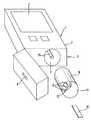
図1〜図3は、試料の、特に血液、尿または唾液のような生体液の医療上有意な成分を検査するための、小型で携帯可能な手持ち式分析装置1の異なる図を示す。図1に示した手持ち式分析装置1は、血中グルコースのレベルを測定するために用いられ、従来型の電池または太陽電池の形態の、一体化された電源2を有する。分析結果は、ディスプレイ3、好ましくは省電力型の液晶ディスプレイまたはOLED(有機EL)ディスプレイを用いて表示される。手持ち式分析装置1は、交換可能な回転ドラム式マガジン6をマガジン区画7に受容するための装着用開口部5を備えたハウジング4を有し、回転ドラム式マガジン6は、マガジン区画7において幾何学的縦軸を中心にして駆動装置により回動可能である。図1は、装着用開口部5が閉じられている手持ち式分析装置1を示す。図2と図3は、装着用開口部5が開かれている手持ち式分析装置1を示す。図3は、構造をより良く示すためにハウジング4の一部だけが切開されており、それにより、マガジン区画7の内部を見ることができる。 1 to 3 show different views of a small and portable hand-held analyzer 1 for examining medically significant components of a sample, in particular a biological fluid such as blood, urine or saliva. The hand-held analyzer 1 shown in FIG. 1 is used to measure blood glucose levels and has an integrated
ハウジング4は、端面に、回転ドラム式マガジン6に収容された使い捨て分析手段10用のアウトプット開口部9を有する。これらの使い捨て手段10は、試料を塗布することができる試験片に構成されていることが好ましい。試験片に含まれる試薬は、試料の医療上有意な成分と反応し、反応の結果が、手持ち式分析装置1の分析装置を用いて分析される。そのような分析装置は、たとえば試験片に構成されている使い捨て手段10の色の変化を検出する分析センサとして機能する光学センサを有する、または試料の伝導率の変化を判定するセンサを有する。 The housing 4 has an
回転ドラム式マガジン6は、幾何学的な縦軸の周囲に環状に配置された多数のチャンバ12を有し、これらのチャンバは、使い捨て分析手段10を収容する。チャンバ12は、回転ドラム式マガジン6を1段ずつ回動させることによって、取出し位置に次々と配置することができるために、使い捨て手段10は、必要に応じて回転ドラム式マガジン6の各々のチャンバ12から取り出し、さらに、ハウジング4のアウトプット開口部9を介して排出することができる。 The
そのようなチャンバ12の数は、選択可能である。一般に、チャンバ12の数は10〜100が好都合であるが、チャンバ12の数は15〜30であることが好ましい。チャンバ12の各々は、回転ドラム式マガジン6の端面に使い捨て手段10を取り出すための取出し用開口部13を有し、また、取出し用開口部13の反対側に、取出し装置16のプッシュ・ロッド15を挿入するための挿入用開口部14を有する。挿入用開口部14および取出し用開口部13は、使い捨て手段10を保護するために密封フィルム17によって封止されている。欧州特許出願公開第1022565号明細書に説明されているように、使い捨て手段10は、プッシュ・ロッド15で挿入用開口部14の密封フィルム17に孔を開けるとともに、使い捨て手段10で取出し用開口部13の密封フィルム17に孔を開けるようにプッシュ・ロッド15を用いることによって、チャンバ12から押し出すことができる。 The number of
回転ドラム検査装置8を用いて、挿入用開口部14の1つが密封フィルム17によって封止されている、従って使用予定の使い捨て手段10がそこに収容されているか否かについての情報を含む信号が生成される。回転ドラム検査装置18により、回転ドラム式マガジン6が完全に空になっているか否かを検査することが可能になる。回転ドラム検査装置18の代替としてまたはそれに追加して、回転ドラム式マガジン6のチャンバ12から取り出した使い捨て手段の数を数えるために、計数装置を装備して、最大数に達したとき「回転ドラム空」の信号を出力するようにしてもよい。 Using the rotating
図4は、搬送路に使い捨て分析手段10が正しく配置されていることを検出し、その際、さらに、位置決め装置として正しく配置されることを支援する、および/または正しい配置を保持させる検査ユニット20の構造を示す概略図である。 FIG. 4 detects that the disposable analysis means 10 is correctly placed in the transport path, and in this case further supports the correct placement as a positioning device and / or maintains the correct placement. It is the schematic which shows the structure of these.
検査ユニット20は、本質的には制御ユニット40、光学センサ30および電気スイッチ21からなる。光学センサ30と電気スイッチ21は、搬送路に使い捨て分析手段10が配置されていることを検知して、制御ユニット40に、配置されていることを示すスイッチ信号を発信するおよび/または対応するセンサ信号を発信する機能を共に有し、これにより、制御ユニット40は、これら信号に対して共通の分析を行って手持ち式分析装置1および/またはその各々の要素を制御することが可能になる。 The
電気スイッチ21は、変位可能であり、また、使い捨て分析手段10の方向に先細になる円錐形端部23を備えるよう形成されるとともに、使い捨て分析手段10に割り当てられたペグ22を有する。ペグ22の先細の円錐形端部23は、使い捨て手段10の測定位置において、使い捨て分析手段10の凹み26に侵入するとともに、端部23が先細の円錐形であることにより、それを位置付けることができるように構成されている。位置を確保するためのこの配置する操作により、手持ち式分析装置1の、たとえば光学センサ30により実施されることもある分析センサによって、使い捨て手段10の信頼性の高い光学的分析が確実なものにされる。従って、光学センサ30を用いることにより、使い捨て手段10が正しく配置されていることを高い信頼性を持って、光学的に検出する操作も、また、確実に行うことが可能になる。凹み26は、また、使い捨て手段10を貫通する孔に形成してもよい。このことは、図4において、凹み26の一点鎖線によって示されている。電気スイッチ21のその他の有利な実施形態については、欧州特許出願公開第1508807号明細書に説明されている。 The
しかし、図4は、分析が実施される、搬送路の測定位置には配置されていない使い捨て手段10を示す。従って、ペグ22の先細の円錐形端部23は、使い捨て手段10の凹み26および/または孔に侵入することなく、使い捨て手段10の表面に当接している。使い捨て手段10は、矢印の方向に図示した位置まで搬送路に搬入され、そこで、搬送路におけるその正しい配置が検査ユニット20によって検証される。この検証の際に、使い捨て手段10が、搬送路の検査位置に位置付けられているか否かを、すなわち回転ドラム式マガジンのチャンバから取出し装置によって搬送されて、いわば、この検査位置に到達しているか否かを確認するための検査が実施される。使い捨て手段10が(図示した検査位置において)正しく配置されていることを検査後に、それは、測定位置に到達するまで矢印の方向にさらに搬送され、そこで、端部23が凹み26に侵入しかつ分析が行われる。 However, FIG. 4 shows the disposable means 10 not being located at the measurement position of the transport path where the analysis is performed. Accordingly, the tapered
使い捨て手段10は、搬送路の支持面29上の電気スイッチ21の領域および/または光学センサ30の領域に配置される。使い捨て分析手段10を導入することにより、ペグ22は、端部23が支持面29に接触している当接位置を離れて、ここに図示した位置まで上向きに変位し、そこで、使い捨て手段10の上側に当接する。この変位は、使い捨て手段10の矢印方向への前進と、先細の円錐形端部23のアウトフロー縁に沿った摺動とによって引き起こされる。搬送路および/または支持面29に直交する方向へのペグ22のこの変位は、バネ24が発生するスプリング力に抗して起こる。バネ24は、使い捨て手段10がスプリング力に抗して変位位置、たとえばここに図示した位置までペグ22を変位させるまで、それを当接位置に確実に保持する。 The disposable means 10 is arranged in the region of the
ペグ22の変位に従い、電気接点25は、ペグ22およびペグ22と接点バネ27の間の機械的接点19によって開閉される。この電気接点25の2つの接点の接触は、可動式接点バネ27および固定式板バネ28によって行われる。ここに説明した状態のとき、ペグ22は、接点バネ27と板バネ28の間の接触によって電気接点25を閉じ、それにより、使い捨て手段10が正しく配置されていること(その存在)を示す電気信号を発生する。ペグ22が当接位置にあるとき、すなわち使い捨て手段10が非存在のとき、接点バネ27と板バネ28の間の電気接点25は、機械的接点19が接点バネ27を押下するために開き、それにより、使い捨て手段が存在しないことを示す信号が生じる。使い捨て手段10を搬送路に挿入したとき、接点バネ27は板バネ28の方にそらされて、電気接点25を閉じるために、制御ユニット40は、使い捨て手段10が正しく配置されている状態であることを示す電気スイッチ信号を受信する。接点バネ27と板バネ28からなる電気接点25は閉じられる。 According to the displacement of the
搬送路に使い捨て分析手段10が存在しない場合には、ペグ22は、バネ24によって当接位置に動かされて支持面29に接触した状態になるために、接点バネ27を板バネ28に向けて最早押圧することはない。電気接点25は開かれ、電気スイッチ信号が制御ユニット40に送信されることはない。このことは、使い捨て分析手段10が電気スイッチ21の監視領域に存在しないというスイッチ情報であることを意味する。 When the disposable analysis means 10 is not present in the conveyance path, the
このスイッチ状態のとき、電気接点25は開く。手持ち式分析装置1は、使用中以外およびユーザが運搬しているとき、通常はこのスイッチ状態にある。特にポケットに入れてまたは衣服の下で運搬されているとき、粉塵が手持ち分析装置1のハウジング4の開口部を介して侵入して、ハウジング4内部に残留する危険がある。電気スイッチ21の電気接点25の領域に侵入して、接点バネ27と板バネ28の間の電気的接触を阻止する粉塵は、特に有害である。このとき、存在する使い捨て分析手段10がペグ22をそらせるが、粉塵によって阻止されているために、接触に至らせることはできない。電気的接触がないために、制御ユニット40は、使い捨て分析手段10が正しく配置されていることおよび/または存在することについての情報をまったく受け取ることができない。ペグ22または機械的接点19の機械的動作も、また、粉塵によって妨げられる。 In this switch state, the
電気スイッチ21は、使い捨て手段10の方向に、限定された周波数範囲の光を照射するLED31を有する能動的な光学センサ30に構成されている。図4には図示されていない実施形態において、光学センサ30は、支持面29に面する側とは反対側の、使い捨て手段10側に配置されている。その場合、図4において、光学センサ30は、使い捨て手段10の上方、すなわち電気スイッチ21と同じ側で、後者の隣に直接接して配置される。光学センサ30に面する、支持面29の領域は、光学センサ30の領域の黒色に着色されることが好ましい。これにより、少量の光だけが支持面29によって後方散乱を起こす。使い捨て手段10が光学センサ30からの光の照射を受ける領域に位置付けられる場合、使い捨て手段10は、較正のために分析の一部に用いられる明るい面、たとえば白色領域(いわゆる白レベル調節部)のような特に白い面を一般に有するために、反射光の量が大きく増加する。反射光は、光学センサ30の光検出器32によって検出される。これら2つの状態は、反射光の光量と光検出器32が受光した光量とが大きく異なるために、光学センサ30によってこれら2つの状態を非常に高い信頼性を持って区別することができる。光学センサ30は、使い捨て手段10が搬送路に、よって支持面29上に正しく配置された状態にあること、または搬送路に使い捨て手段10が存在しない状態にあることのいずれか一方に対応したセンサ信号を制御ユニット40に送信する。制御ユニット40は、電気スイッチ21と光学センサ30の2つの信号を一緒に分析するために、センサ信号を用いて電気スイッチ信号の検査および/または検証が実施されることになる。 The
図4に示した実施形態において、光学センサ30は、支持面29に面する使い捨て手段10側に配置されている。従って、光学センサ30は、使い捨て手段10の下方、すなわち電気スイッチ21とは反対側の使い捨て手段10側に位置付けられる。このために、支持面29は、光学センサ30の領域に開口部または透明な窓33を有する。光学センサ30からの照射を受ける領域に使い捨て手段10が存在しない場合、少量の散乱光だけが、光検出器32に送り返される。しかし、光学センサ30からの照射を受けるとともに、分析の一部として較正に用いられる領域、たとえば白色領域(いわゆる白レベル調節部)に、明るい面、特に白色面を一般に有する使い捨て手段10が存在する場合には、反射光の光量が大きく増加する。反射光は、光学センサ30の光検出器32によって検出される。これら2つの状態は、反射光の光量と光検出器32が受光した光量とが大きく異なるために、光学センサ30によってこれら2つの状態を非常に高い信頼性を持って区別することができる。センサは、使い捨て手段10が搬送路に、よって支持面29上に正しく配置された状態にあること、または搬送路に使い捨て手段10が存在しない状態にあることのいずれか一方に対応したセンサ信号を制御ユニット40に送信する。制御ユニット40は、電気スイッチ21と光学センサ30の2つの信号を一緒に分析するために、センサ信号を用いて電気スイッチ信号の検査および/または検証が実施されることになる。 In the embodiment shown in FIG. 4, the
図4を用いて説明した両実施形態において、その後の計測過程は、使い捨て手段10が図4に示した使い捨て手段10の位置に正しく配置されていることを検証した後に実施される。複数の実施形態のこの計測過程において、分析は、使い捨て手段10がこの位置にあるとき、分析センサを用いて直ちに実施される。しかし、光学センサ30が同時に分析センサとしても用いられる場合または分析センサが光学センサ30と一体化されている場合には、たとえば光度測定検査領域が分析センサの可視領域に入るまで、使い捨て手段10を、測定位置に向けてここに示した位置より矢印方向にさらに搬送することが一般には必要である。使い捨て手段10が測定位置にあるとき、ペグ22の端部23は、凹み26に侵入することができる。このとき、電気接点25は、いずれかが閉じた状態を維持できるために、正しく配置されたこと、すなわち使い捨て手段10の存在を示す信号がさらに発信される。しかし、選好実施形態においては、電気接点25は、使い捨て手段10が測定位置にあるとき開いて、使い捨て手段10は測定位置に到達したことを示す信号を発信する。開いた電気接点25が、使い捨て手段10は一見存在しないということを示す事実は、制御ユニット40による対応したシーケンス制御に組み込むことが可能であり、その場合、使い捨て手段10が測定位置に正しく配置されていることは、事前に検証されている。 In both embodiments described with reference to FIG. 4, the subsequent measurement process is performed after verifying that the disposable means 10 is correctly placed at the position of the disposable means 10 shown in FIG. 4. In this measurement process of embodiments, the analysis is performed immediately using an analytical sensor when the disposable means 10 is in this position. However, if the
図5は、手持ち式分析装置を検証および/または制御するための操作を、特に検査ユニット20の機能に注目して、フロー・チャートの形式で模式的に例示する。 FIG. 5 schematically illustrates operations for verifying and / or controlling the hand-held analyzer in the form of a flow chart, with particular attention to the function of the
工程S1において、ボタンを操作して手持ち式分析装置1を起動した後に、試験片に構成されている使い捨て分析手段10が要求され、工程S2において、帯片状の使い捨て手段10が、回転ドラム式マガジン6から取出し装置16によって取り出されて搬送路に配置され、さらに分析センサの方向に搬送される。帯片状の使い捨て手段10は、その後、電気スイッチ21および/または光学センサ30の領域に到達する。電気スイッチ21のペグ22は、帯片状の使い捨て手段10によって変位させられて、板バネ28と接点バネ27の間の電気接点を閉じる。これにより、使い捨て手段10が正しく配置された状態であることを示すスイッチ信号が、制御ユニット40に送られる。この検出は、工程S3において行われる。電気スイッチ21によって、使い捨て手段10が正しく配置されたことについてのスイッチ信号が制御ユニット40に送られた場合、工程S4において、分析センサが作動して、グルコースのような医療上有意な成分について、分析対象の試料の分析が実施される。計測結果は、ディスプレイ3によって出力される。この計測手順は、使い捨て手段10が正しく配置された状態あることについての電気スイッチ21の検出結果は信頼性が非常に高いために、分析センサを用いて、計測過程を簡単かつ直接的な手法で開始することができる。 In step S1, after operating the button to activate the hand-held analyzer 1, the disposable analysis means 10 configured as a test piece is required. In step S2, the strip-like disposable means 10 is a rotating drum type. It is taken out from the
工程S3において、電気スイッチ21が、使い捨て手段10は正しく配置された状態にないことを検出し、その情報を制御ユニット40に送るような場合には、その後に、正しく配置されていることの光学的検出が光学センサ30によって行われる。これは、工程S5において行われる。光学センサ30はこのケースのときにだけ作動し、それ以外は動作を停止している。従って、光学センサ30は、電気スイッチ21のスイッチ信号が、使い捨て分析手段10は搬送路の正しい位置に存在しないことを示すときにだけ、電気スイッチ21のスイッチ信号を検査および/または検証するために作動する。従って、手持ち式分析装置1は、非常にエネルギー消費の小さい動作を行うことが可能になる。光学センサ30は、取出し装置16が使い捨て分析手段10を搬送路上に搬送するために作動したにも拘らず、電気スイッチ21のスイッチ信号が、使い捨て分析手段10は搬送路の正しい位置に存在しないことを示すとき、電気スイッチ21のスイッチ信号を検査および/または検証するために、自動的に作動するようになっていることが有利である。 In step S3, if the
工程S5において、使い捨て手段10は光学センサ30の検出範囲内に存在しないことが判明した場合、このことは電気スイッチ信号を確認することになるために、制御ユニット40は、取出し装置16を作動させて回転ドラム式マガジン6の次のチャンバから次の使い捨て手段10を取り出して、それを分析センサの方向に搬送する。これにより、工程S1における要求にしたがって、使い捨て手段10が、所望の分析を実施するために確実に搬送される。工程S8において、回転ドラム検査装置18または計数装置により、回転ドラムが完全に空になっていて、回転ドラム式マガジン6に最早使い捨て手段10が存在しないことが判明した場合、このことは、工程S9において、ディスプレイ3を用いてユーザに報告され、手持ち式分析装置1のその後の動作は停止される。 In step S5, if it is found that the disposable means 10 is not within the detection range of the
工程S5において、光学センサ30により使い捨て手段10の正しい配置、よって存在が検出され、対応するセンサ信号が制御ユニット40に送られている場合には、この矛盾する信号内容は制御ユニット40により検出されるとともに、手持ち式分析装置1は故障していると判断される。この故障は、帯片状の使い捨て手段10が電気スイッチ21の領域および光学センサ30の範囲にあるにも拘らず、電気スイッチ21によって検出されないために、工程S4における計測動作が開始されないことを特徴とする。この場合には、工程S6において、ディスプレイ3によって、この故障を指摘するエラーメッセージが出力されるとともに、ユーザに対して、スイッチ21の電気接点27、28のクリーニングをするようにとの指示が出される。このことは、手持ち式分析装置1の対応するクリーニングプログラムを起動することによって自動的に行われる。これにより、電気スイッチ21の機能が復元し、よって手持ち式分析装置1の機能が復元する。 In step S5, if the
エラーメッセージの出力に加え、工程S7において、使い捨て手段10は装置から押し出されるために、クリーニングが無事行われた後には、その後の分析が無事行われる可能性が大きくなる。 In addition to the output of the error message, since the disposable means 10 is pushed out of the apparatus in step S7, there is a high possibility that the subsequent analysis will be safely performed after the cleaning is successfully performed.
従って、工程S5において、電気スイッチ21のスイッチ信号および光学センサ30のセンサ信号の分析が行われ、手持ち式分析装置1は、これら信号を制御ユニット40によって比較した結果にしたがって制御される。ここに説明した動作手順を採用することにより、取出し装置16により使い捨て手段10が回転ドラム式マガジン6から連続して搬出されたにも拘らず分析が行われない、いわゆる試験片の継続積層の故障および/または搬送路にすでにある使い捨て手段10の上に別の使い捨て手段10を押し出すことによって、搬送路に使い捨て手段10詰まりを引き起こす試験片詰まりの故障を確実にかつ大幅に低減できる。 Therefore, in step S5, the switch signal of the
上述した方法の工程は、概ね以下のように特徴付けることができる。S1手持ち式分析装置起動、S2試験片取出し、S3スイッチ信号問い合わせ、S4分析開始、S5センサ信号問い合わせ、S6エラーメッセージ、S7試験片取出し、S8マガジンからの供給の検査、およびS9空マガジン。 The process steps described above can be generally characterized as follows. S1 hand-held analyzer activation, S2 specimen removal, S3 switch signal inquiry, S4 analysis start, S5 sensor signal inquiry, S6 error message, S7 specimen removal, inspection of supply from S8 magazine, and S9 empty magazine.
1 手持ち式分析装置
2 電源
3 ディスプレイ
4 ハウジング
5 装着用開口部
6 回転ドラム式マガジン
7 マガジン区画
9 アウトプット開口部
10 使い捨て手段
12 チャンバ
13 取出し用開口部
14 挿入用開口部
15 プッシュ・ロッド
16 取出し装置
17 密封フィルム
18 回転ドラム検査装置
19 機械的接点
20 検査ユニット
21 電気スイッチ
22 ペグ
23 先細の円錐形端部
24 バネ
25 電気接点
26 凹み
27 接点バネ
28 板バネ
29 支持面
30 光学センサ
31 LED
32 光検出器
33 窓
40 制御ユニット
S1 手持ち式分析装置起動
S2 試験片取出し
S3 スイッチ信号問い合わせ
S4 分析開始
S5 センサ信号問い合わせ
S6 エラーメッセージ
S7 試験片取出し
S8 マガジンからの供給の検査
S9 空マガジンDESCRIPTION OF SYMBOLS 1
32
Claims (13)
Translated fromJapaneseディスプレイ(3)と、
ハウジング(4)と、
使い捨て分析手段(10)、特に試験片を収容する交換式マガジン(6)、特に回転ドラム式マガジンを受容するための装着用開口部(5)と、
使い捨て分析手段(10)を前記マガジン(6)から取り出して、それを搬送路上に搬送するための取出し装置(16)と、
前記搬送路において、使い捨て分析手段(10)の供給を受ける分析センサと、
使い捨て分析手段(10)が前記搬送路に正しく配置されていることを検出する検査ユニット(20)とを有し、
前記検査ユニット(20)は、
使い捨て分析手段(10)が前記搬送路に配置されていることを機械的に検知し、使い捨て分析手段(10)の存在を示す少なくとも1つのスイッチ位置を取り、さらに前記使い捨て分析手段(10)の配置状態に対応するスイッチ信号を発信する電気スイッチ(21)と、
使い捨て分析手段(10)が前記搬送路に配置されていることを光学的に感知して、前記使い捨て分析手段(10)の配置状態に対応するセンサ信号を発信する光学センサ(30)と、
前記電気スイッチ(21)のスイッチ信号を分析し、前記光学センサ(30)のセンサ信号を分析し、さらに、これら信号を比較した結果にしたがって前記手持ち式分析装置(1)を制御する制御ユニット(40)とを有することを特徴とする手持ち式分析装置(1)。In a hand-held analyzer (1) for inspecting samples, particularly biological fluids, for medically significant components,
Display (3);
A housing (4);
A disposable analysis means (10), in particular a replaceable magazine (6) for receiving a test piece, in particular a mounting opening (5) for receiving a rotating drum magazine;
A take-out device (16) for taking out the disposable analysis means (10) from the magazine (6) and transporting it on the transport path;
An analysis sensor that receives supply of the disposable analysis means (10) in the transport path;
An inspection unit (20) for detecting that the disposable analysis means (10) is correctly arranged in the conveyance path;
The inspection unit (20)
It is mechanically detected that the disposable analysis means (10) is disposed in the conveyance path, takes at least one switch position indicating the presence of the disposable analysis means (10), and further includes the disposable analysis means (10). An electrical switch (21) for transmitting a switch signal corresponding to the arrangement state;
An optical sensor (30) that optically senses that the disposable analysis means (10) is disposed in the transport path, and transmits a sensor signal corresponding to the arrangement state of the disposable analysis means (10);
A control unit (1) that analyzes the switch signal of the electrical switch (21), analyzes the sensor signal of the optical sensor (30), and controls the hand-held analyzer (1) according to the result of comparing these signals. 40) and a hand-held analyzer (1).
前記手持ち式分析装置(1)は、
ディスプレイ(3)と、
使い捨て分析手段(10)をマガジン、特に回転ドラム式マガジン(6)から取り出して、それを搬送路上に搬送するための取出し装置(16)と、
前記搬送路において使い捨て分析手段(10)の供給を受けることができる分析センサと、
使い捨て分析手段(10)が前記搬送路に正しく配置されていることを検出する検査ユニット(20)とを有し、
前記手持ち式分析装置(1)の起動、
および、それに続く前記マガジン(6)からの使い捨て分析手段(10)の取出しと、前記搬送路上へのそれの搬送の後に、
使い捨て分析手段(10)は前記搬送路に配置されていることを機械的に検知する電気スイッチ(21)の信号と、使い捨て分析手段(10)は前記搬送路に配置されていることを光学的に感知する光学センサ(30)の信号とが制御ユニット(40)によって分析され、かつ、これら信号を比較した結果にしたがって前記手持ち式分析装置(1)は制御されることを特徴とする手持ち式分析装置(1)を動作させる方法。In a method of operating a hand-held analyzer (1) for examining a sample, particularly a biological fluid, for a medically significant component,
The handheld analyzer (1)
Display (3);
A take-out device (16) for removing the disposable analysis means (10) from the magazine, in particular the rotating drum magazine (6), and transporting it on the transport path;
An analytical sensor capable of receiving a supply of disposable analytical means (10) in the transport path;
An inspection unit (20) for detecting that the disposable analysis means (10) is correctly arranged in the conveyance path;
Activation of the handheld analyzer (1),
And subsequent removal of the disposable analysis means (10) from the magazine (6) and its transport onto the transport path,
A signal of an electrical switch (21) that mechanically detects that the disposable analysis means (10) is arranged in the conveyance path, and an optical that the disposable analysis means (10) is arranged in the conveyance path The signal of the optical sensor (30) that senses the signal is analyzed by the control unit (40), and the hand-held analyzer (1) is controlled according to the result of comparing these signals. A method of operating the analyzer (1).
Applications Claiming Priority (1)
| Application Number | Priority Date | Filing Date | Title |
|---|---|---|---|
| EP07010017AEP1995594B1 (en) | 2007-05-19 | 2007-05-19 | Handheld analysis device for investigating a sample |
Publications (2)
| Publication Number | Publication Date |
|---|---|
| JP2008292479A JP2008292479A (en) | 2008-12-04 |
| JP4604109B2true JP4604109B2 (en) | 2010-12-22 |
Family
ID=38669973
Family Applications (1)
| Application Number | Title | Priority Date | Filing Date |
|---|---|---|---|
| JP2008124594AExpired - Fee RelatedJP4604109B2 (en) | 2007-05-19 | 2008-05-12 | Hand-held analyzer for sample inspection |
Country Status (8)
| Country | Link |
|---|---|
| EP (1) | EP1995594B1 (en) |
| JP (1) | JP4604109B2 (en) |
| CN (1) | CN101308133A (en) |
| AT (1) | ATE436014T1 (en) |
| CA (1) | CA2630719C (en) |
| DE (1) | DE502007001040D1 (en) |
| ES (1) | ES2326496T3 (en) |
| PL (1) | PL1995594T3 (en) |
Cited By (1)
| Publication number | Priority date | Publication date | Assignee | Title |
|---|---|---|---|---|
| US8394637B2 (en) | 2008-06-02 | 2013-03-12 | Roche Diagnostics Operations, Inc. | Handheld analyzer for testing a sample |
Families Citing this family (5)
| Publication number | Priority date | Publication date | Assignee | Title |
|---|---|---|---|---|
| WO2012076683A1 (en)* | 2010-12-09 | 2012-06-14 | Arthur Queval | Micro-fluidic device for the analysis of a fluid sample |
| CN103837474A (en)* | 2012-11-20 | 2014-06-04 | 永龄生技股份有限公司 | Test Strip Reader and Diagnostic Device |
| CN108814621B (en)* | 2018-04-11 | 2021-09-07 | 于雪 | Protection formula passes catch disease blood specimen collection system |
| CN109567827B (en)* | 2018-11-20 | 2019-12-13 | 陈欣 | clinical laboratory's intelligence indicates blood inspection device |
| CN114551140B (en)* | 2020-11-25 | 2023-12-29 | 广州好芝生物科技有限公司 | Switch assembly, detection device and control method based on switch assembly |
Family Cites Families (12)
| Publication number | Priority date | Publication date | Assignee | Title |
|---|---|---|---|---|
| JPS61165679A (en)* | 1985-01-18 | 1986-07-26 | Matsushita Electric Ind Co Ltd | Optical paper detection device |
| JPS61278781A (en)* | 1985-06-04 | 1986-12-09 | Fuji Xerox Co Ltd | Sensor device |
| JP2812625B2 (en)* | 1992-10-19 | 1998-10-22 | 株式会社日立製作所 | Liquid sample automatic analyzer |
| US6335203B1 (en)* | 1994-09-08 | 2002-01-01 | Lifescan, Inc. | Optically readable strip for analyte detection having on-strip orientation index |
| EP0901634B1 (en)* | 1996-05-30 | 2002-03-20 | Radiometer Medical A/S | A system for determining at least one parameter of at least one sample of a physiological liquid and a cassette |
| DE69626016T2 (en)* | 1996-09-27 | 2004-01-08 | Inverness Medical Switzerland Gmbh | Test kit and devices |
| DE19844500A1 (en)* | 1998-09-29 | 2000-03-30 | Roche Diagnostics Gmbh | Process for the photometric evaluation of test elements |
| EP1031470A1 (en)* | 1999-02-25 | 2000-08-30 | Siemens Aktiengesellschaft | Device for the protection of occupants in a vehicle |
| AU2003296703A1 (en)* | 2002-12-23 | 2004-07-14 | F.Hoffmann-La Roche Ag | Transport device for transporting test strips in an analysis system |
| DE10338446A1 (en)* | 2003-08-21 | 2005-03-31 | Roche Diagnostics Gmbh | Positioning device for a test element |
| DE10361261B4 (en)* | 2003-12-24 | 2006-02-09 | Roche Diagnostics Gmbh | Handheld analyzer |
| DE102004010529B4 (en)* | 2004-03-04 | 2007-09-06 | Roche Diagnostics Gmbh | Handheld analyzer |
- 2007
- 2007-05-19ATAT07010017Tpatent/ATE436014T1/enactive
- 2007-05-19ESES07010017Tpatent/ES2326496T3/enactiveActive
- 2007-05-19PLPL07010017Tpatent/PL1995594T3/enunknown
- 2007-05-19EPEP07010017Apatent/EP1995594B1/enactiveActive
- 2007-05-19DEDE502007001040Tpatent/DE502007001040D1/enactiveActive
- 2008
- 2008-05-07CACA2630719Apatent/CA2630719C/ennot_activeExpired - Fee Related
- 2008-05-12JPJP2008124594Apatent/JP4604109B2/ennot_activeExpired - Fee Related
- 2008-05-16CNCNA2008100990773Apatent/CN101308133A/enactivePending
Cited By (1)
| Publication number | Priority date | Publication date | Assignee | Title |
|---|---|---|---|---|
| US8394637B2 (en) | 2008-06-02 | 2013-03-12 | Roche Diagnostics Operations, Inc. | Handheld analyzer for testing a sample |
Also Published As
| Publication number | Publication date |
|---|---|
| ATE436014T1 (en) | 2009-07-15 |
| JP2008292479A (en) | 2008-12-04 |
| CN101308133A (en) | 2008-11-19 |
| EP1995594A1 (en) | 2008-11-26 |
| DE502007001040D1 (en) | 2009-08-20 |
| ES2326496T3 (en) | 2009-10-13 |
| CA2630719C (en) | 2011-04-12 |
| PL1995594T3 (en) | 2009-12-31 |
| CA2630719A1 (en) | 2008-11-19 |
| EP1995594B1 (en) | 2009-07-08 |
Similar Documents
| Publication | Publication Date | Title |
|---|---|---|
| US8394637B2 (en) | Handheld analyzer for testing a sample | |
| US7964147B2 (en) | Hand-held analysis device | |
| US4420566A (en) | Method and apparatus for detecting sample fluid on an analysis slide | |
| JP4604109B2 (en) | Hand-held analyzer for sample inspection | |
| EP2171431B1 (en) | Microelectronic sensor device for optical examinations on a wetted surface | |
| WO2009122993A1 (en) | Blood coagulation analyzer, method of analyzing blood coagulation and computer program | |
| JP4704402B2 (en) | Method and system for analyzing samples on test elements | |
| EP0087466B1 (en) | Method and apparatus for detecting sample fluid | |
| US11054433B2 (en) | Automated analyzer and control method for same | |
| JPS6321139B2 (en) | ||
| CN106471356B (en) | Automatic analysis device | |
| GB2458778A (en) | Chromatography device with inclination sensor | |
| JP6710535B2 (en) | Automatic analyzer | |
| KR20150066722A (en) | Test apparatus and test method of test apparatus | |
| KR20150012101A (en) | Test Apparatus and Control Method thereof | |
| JP2004333439A (en) | Liquid volume measurement method and device | |
| JP2013024797A (en) | Analyzer and analysis method | |
| US8845964B2 (en) | Sample analyzer and method for controling a sample analyzer | |
| JPS61262639A (en) | Automatic analyser | |
| JPS6082865A (en) | Automatic chemical analysis apparatus | |
| JP7539547B2 (en) | Automatic analyzer and sample dispensing method | |
| HK1123603A (en) | Handheld analyzer for testing a sample | |
| KR20190053258A (en) | Method and method for determining analyte concentration of body fluid | |
| CN120283157A (en) | Real-time cuvette monitoring | |
| JP2004101293A (en) | Automatic analytical instrument |
Legal Events
| Date | Code | Title | Description |
|---|---|---|---|
| RD03 | Notification of appointment of power of attorney | Free format text:JAPANESE INTERMEDIATE CODE: A7423 Effective date:20100525 | |
| A977 | Report on retrieval | Free format text:JAPANESE INTERMEDIATE CODE: A971007 Effective date:20100913 | |
| TRDD | Decision of grant or rejection written | ||
| A01 | Written decision to grant a patent or to grant a registration (utility model) | Free format text:JAPANESE INTERMEDIATE CODE: A01 Effective date:20100921 | |
| A01 | Written decision to grant a patent or to grant a registration (utility model) | Free format text:JAPANESE INTERMEDIATE CODE: A01 | |
| A61 | First payment of annual fees (during grant procedure) | Free format text:JAPANESE INTERMEDIATE CODE: A61 Effective date:20101004 | |
| FPAY | Renewal fee payment (event date is renewal date of database) | Free format text:PAYMENT UNTIL: 20131008 Year of fee payment:3 | |
| R150 | Certificate of patent or registration of utility model | Free format text:JAPANESE INTERMEDIATE CODE: R150 | |
| LAPS | Cancellation because of no payment of annual fees |