JP4603607B2 - Wheel drive wheel drive swivel - Google Patents
Wheel drive wheel drive swivelDownload PDFInfo
- Publication number
- JP4603607B2 JP4603607B2JP2008239633AJP2008239633AJP4603607B2JP 4603607 B2JP4603607 B2JP 4603607B2JP 2008239633 AJP2008239633 AJP 2008239633AJP 2008239633 AJP2008239633 AJP 2008239633AJP 4603607 B2JP4603607 B2JP 4603607B2
- Authority
- JP
- Japan
- Prior art keywords
- wheel
- rotation
- reverse rotation
- friction wheel
- conical friction
- Prior art date
- Legal status (The legal status is an assumption and is not a legal conclusion. Google has not performed a legal analysis and makes no representation as to the accuracy of the status listed.)
- Active
Links
Images


Landscapes
- Friction Gearing (AREA)
Description
Translated fromJapaneseこの出願の発明は、車椅子の分野に属する。車輪を直接手で回転させる形式のものを対象としたものではなく、足踏みペダルの駆動力で自走する形式の車椅子に好適なものである。しかし、電動モータで同様に自走する形式の車椅子への適用を排除するものではない。そしてその特徴点は、左右の車輪の回転速度を正転領域から停止領域、更には逆転領域に及ぶまで連続的に可変とし、自走式の車椅子の舵取りに伴い、車輪を駆動旋回させる装置の分野に属する。 The invention of this application belongs to the field of wheelchairs. It is not intended for a type in which the wheel is directly rotated by hand, but is suitable for a wheelchair that is self-propelled by the driving force of a foot pedal. However, it does not exclude application to a wheelchair that is self-propelled by an electric motor. And the feature point is that the rotation speed of the left and right wheels is continuously variable from the forward rotation region to the stop region, and further to the reverse rotation region, and the device that drives and turns the wheels with the steering of the self-propelled wheelchair. Belonging to the field.
ステアリング機構を有する移動台車で、超信地旋回を可能とする機構は、「片輪駆動・片輪操舵」であり、超信地旋回が可能なのは一方向の回転のみであったり、駆動されていない側の車輪はフリーの状態であり、斜面を横切る場合などに安定した走行は困難であった。また、ステアリング操作で車輪やキャスタの角度を変更することによる旋回は、小回りが効かないという欠点があった。 The mechanism that enables super-revolution in a mobile trolley with a steering mechanism is “single-wheel drive / single-wheel steering”, and super-revolution can only be performed in one direction or driven. The wheel on the non-side was in a free state, and stable running was difficult when crossing a slope. In addition, turning by changing the angles of wheels and casters by a steering operation has a drawback that a small turn does not work.
一方で、円錐形の摩擦車と摩擦ローラを用いた無段変速機は、例えば特許文献1(実公昭37−12420号公報)に記載されているように周知ではあるが、円錐型の摩擦車を用いて、正転領域から停止領域を経て逆転領域にまで及ぶ無段変速を可能としたものは不知である。On the other hand, a continuously variable transmission using a conical friction wheel and a friction roller is well known as described in, for example, Patent Document 1 (Japanese Utility Model Publication No. 37-12420), but a conical friction wheel. It is unknown that the stepless speed change from the normal rotation region to the stop region through the reverse rotation region can be performed by using.
もっとも、摩擦車を用いた無段変速機であって、正転領域から停止領域を経て逆転領域にまで及ぶ無段変速を可能としたものは、例えば特許文献2(特公平7−74667号公報)により知られている。
この出願の発明は、足踏みペダルの駆動力で自走する形式の車椅子に好適な伝動兼旋回装置を提供することを第1の目的とする。車椅子自体、危険防止の観点から、高速走行を目指すものでは決してない。特に、屋内で使用されるリハビリ用の足踏み式車椅子においては、操舵による旋回は小回りも可能であることが好ましいのである。したがって、円滑な小回りはもとより、信地旋回から超信地旋回まで、ハンドルの操作量に応じて所望の旋回特性を得る駆動兼旋回装置を提供することが第2の目的である。 The first object of the invention of this application is to provide a transmission and turning device suitable for a wheelchair of a type that self-propels with the driving force of a foot pedal. The wheelchair itself is never aimed at high-speed driving from the viewpoint of danger prevention. In particular, in a rehabilitation foot-operated wheelchair used indoors, it is preferable that turning by steering is possible. Accordingly, a second object is to provide a drive and turning device that obtains a desired turning characteristic in accordance with the amount of operation of the steering wheel, from smooth turning to super turning, as well as smooth turning.
上記課題を解決するため、本発明は、単一の駆動源の動力を一対の無段変速機を介して左車輪と右車輪とに独立して出力するようにしてなる車椅子の駆動旋回装置において、一対の無段変速機は共に、正転用と逆転用の円錐型摩擦車を、ゼロ回転用のフローティングホイールを挟んで対向させ、逆転用の円錐型摩擦車の回転を正転用の円錐型摩擦車に逆回転して伝える伝達機構を介して両摩擦車を連結させ、舵取り操作により移動される駆動摩擦ローラを、正転用の円錐型摩擦車、フローティングホイール、逆転用の円錐型摩擦車に連続的に順次接触させ、該駆動摩擦ローラの回転を正回転、ゼロ回転及び逆回転として取出すことで、正転領域と停止領域と逆転領域とを連続的に操作可能に備えたものであることを特徴とする。In order to solve the above-described problems, the present invention provides a wheelchair drive / swivel device configured to independently output the power of a single drive source to a left wheel and a right wheel via a pair of continuously variable transmissions. In both ofthe continuously variable transmissions, the conical friction wheels for forward rotation and reverse rotation are opposed to each other with a floating wheel for zero rotation, and the rotation of the conical friction wheel for reverse rotation is conical friction for forward rotation. Both friction wheels are connected via a transmission mechanism that rotates in reverse to the car, and the drive friction roller that is moved by the steering operation is connected to the conical friction wheel for forward rotation, the floating wheel, and the conical friction wheel for reverse rotation. In order tocontinuously operatethe forward rotation region, the stop region, and the reverse rotation regionby sequentially bringing them into contact with each other and taking out the rotation of the drive friction roller as normal rotation, zero rotation, and reverse rotation. Features.
更に本発明は、正転用の円錐型摩擦車に円筒型摩擦車を一体化し、円筒型摩擦車から車輪に回転を伝えるように設け、舵取り操作により移動される駆動摩擦ローラを、円筒型摩擦車、正転用の円錐型摩擦車、フローティングホイール、逆転用の円錐型摩擦車に連続的に順次接触させ、該駆動摩擦ローラの回転を正回転、ゼロ回転及び逆回転として車輪側に取出すように設けたことを特徴とする。Furthermore, the present invention providesa conical friction wheel for forward rotation and a cylindrical friction wheel that are integrated so that rotation is transmitted from the cylindrical friction wheel to a wheel, and a drive friction roller that is moved by a steering operation is provided with the cylindrical friction wheel. , A conical friction wheel for forward rotation, a floating wheel, and a conical friction wheel for reverse rotation are successively brought into contact with each other, and the drive friction roller is taken out to the wheel side as normal rotation, zero rotation and reverse rotation. characterized in thatwas.
更に本発明は、伝達機構として、逆転用の円錐型摩擦車と太陽歯車とを一体に設け、フローティングホイールと一体の固定軸に遊星歯車を遊嵌し、正転用の円錐型摩擦車に内歯歯車を固設し、該太陽歯車と該遊星歯車と該内歯歯車とにより単純遊星歯車装置を構成すると共に、逆転用の円錐型摩擦車とフローティングホイールとの間には一方向クラッチを介在させたことを特徴とする。
また、本発明は、伝達機構として、逆転用の円錐型摩擦車と太陽歯車とを一体に設け、外部の固定部に一体化されるアングルと一体の固定軸に遊星歯車を遊嵌し、正転用の円錐型摩擦車に内歯歯車を固設し、該太陽歯車と該遊星歯車と該内歯歯車とにより単純遊星歯車装置を構成すると共に、逆転用の円錐型摩擦車にフローティングホイールを遊嵌させたことを特徴としてもよい。Further, according to the present invention, as atransmission mechanism, a conical friction wheel for reverse rotation and a sun gear are integrally provided, a planetary gear is loosely fitted on a fixed shaft integral with a floating wheel, and an internal tooth is attached to the conical friction wheel for forward rotation. A simple planetary gear unit is configured by the sun gear, the planetary gear, and the internal gear, and a one-way clutch is interposed between the conical friction wheel for reverse rotation and the floating wheel. characterized in thatwas.
Further, according to the present invention, as a transmission mechanism, a conical friction wheel for reverse rotation and a sun gear are integrally provided, and a planetary gear is loosely fitted on a fixed shaft integrated with an angle integrated with an external fixing portion. An internal gear is fixed to the diverting conical friction wheel, and the sun gear, the planetary gear, and the internal gear constitute a simple planetary gear unit, and the floating wheel is idled to the reverse conical friction wheel. It may be characterized by being fitted.
更に本発明は、舵取り操作の中立位置においては一対の無段変速機は相等しい正転領域の変速比に選択され、舵取り操作が右に進むにつれて左の車輪に接続される無段変速機の変速比は徐々に高まると共に、右の車輪に接続される無段変速機の変速比は徐々に低下しつつ停止領域を越えて逆転領域に入りその逆転変速比が徐々に高まるように構成し、舵取り操作が左に進むにつれて右の車輪に接続される無段変速機の変速比は徐々に高まると共に、左の車輪に接続される無段変速機の変速比は徐々に低下しつつ停止領域を越えて逆転領域に入りその逆転変速比が徐々に高まるように構成したことを特徴とする。Further, according to the present invention, inthe neutral position of the steering operation, the pair of continuously variable transmissions is selected to have a gear ratio in the same normal rotation region, and as the steering operation proceeds to the right, the continuously variable transmission connected to the left wheel The speed change ratio is gradually increased, and the speed change ratio of the continuously variable transmission connected to the right wheel is gradually lowered while entering the reverse rotation area beyond the stop area, and the reverse speed change ratio is gradually increased. As the steering operation proceeds to the left, the gear ratio of the continuously variable transmission connected to the right wheel gradually increases, and the gear ratio of the continuously variable transmission connected to the left wheel gradually decreases while the stop region is reduced. The present invention is characterized inthat the reverse gear ratio is gradually increased beyond the reverse rotation region .
本発明の車椅子は、簡単な無段変速機構を適用することにより、ハンドル操作で舵取りを行う車椅子の旋回半径を大きなものから小さなものまで無段階に得られるようにすると共に、信地旋回はもとより、超信地旋回に限りなく近いものまでも可能とすることができるので、特に屋内で用いるリハビリ用の足踏み式車椅子に適用して好適である。勿論その優れた操舵性からして、電動型の車椅子に適用することを排除するものではない。 The wheelchair of the present invention allows a stepless turning radius of a wheelchair that is steered by steering operation to be obtained steplessly from a large to a small one by applying a simple continuously variable transmission mechanism, Since it can be as close as possible to ultra-superficial turning, it is particularly suitable for application to a stepping wheelchair for rehabilitation used indoors. Of course, because of its excellent steering performance, application to an electric wheelchair is not excluded.
単一の駆動源の動力を一対の無段変速機を介して左車輪と右車輪とに独立して出力するようにしてなる車椅子の駆動旋回装置である。一対の無段変速機は共に、正転用と逆転用の円錐型摩擦車を、ゼロ回転用のフローティングホイールを挟んで対向させ、逆転用の円錐型摩擦車の回転を正転用の円錐型摩擦車に逆回転して伝える伝達機構を介して両摩擦車を連結させ、舵取り操作により移動される駆動摩擦ローラを、正転用の円錐型摩擦車、フローティングホイール、逆転用の円錐型摩擦車に連続的に順次接触させ、該駆動摩擦ローラの回転を正回転、ゼロ回転及び逆回転として取出すことで、正転領域と停止領域と逆転領域とを連続的に操作可能に備えたものである。Thisis a drive turning devicefor a wheelchair that outputs power of a single drive source independently to a left wheel and a right wheel via a pair of continuously variable transmissions. In both of the pair of continuously variable transmissions, a conical friction wheel for forward rotation and a reverse rotation are opposed to each other with a floating wheel for zero rotation therebetween, and the rotation of the conical friction wheel for reverse rotation is conical friction wheel for forward rotation. Both friction wheels are connected via a transmission mechanism that rotates in reverse, and the drive friction roller that is moved by the steering operation is continuously connected to the conical friction wheel for forward rotation, the floating wheel, and the conical friction wheel for reverse rotation. In order tocontinuously operatethe forward rotation region, the stop region, and the reverse rotation region bytaking out the rotation of the drive friction roller as normal rotation, zero rotation and reverse rotation.
更に、正転用の円錐型摩擦車に円筒型摩擦車を一体化し、円筒型摩擦車から車輪に回転を伝えるように設け、舵取り操作により移動される駆動摩擦ローラを、円筒型摩擦車、正転用の円錐型摩擦車、フローティングホイール、逆転用の円錐型摩擦車に連続的に順次接触させ、該駆動摩擦ローラの回転を正回転、ゼロ回転及び逆回転として車輪側に取出すように設けることが好ましい。Furthermore, a cylindrical friction wheel is integrated with a conical friction wheel for normal rotation, and rotation is transmitted from the cylindrical friction wheel to a wheel. A drive friction roller that is moved by a steering operation is used as a cylindrical friction wheel for normal rotation. It is preferable that the conical friction wheel, the floating wheel, and the conical friction wheel for reverse rotation are successively brought into contact with each other in succession, and the drive friction roller is rotated so as to be taken out to the wheel side as normal rotation, zero rotation and reverse rotation. .
更に、伝達機構として、逆転用の円錐型摩擦車と太陽歯車とを一体に設け、フローティングホイールと一体の固定軸に遊星歯車を遊嵌し、正転用の円錐型摩擦車に内歯歯車を固設し、該太陽歯車と該遊星歯車と該内歯歯車とにより単純遊星歯車装置を構成すると共に、逆転用の円錐型摩擦車とフローティングホイールとの間には一方向クラッチを介在させることが好ましい。Further, as a transmission mechanism, a conical friction wheel for reverse rotation and a sun gear are provided integrally, a planetary gear is loosely fitted on a fixed shaft integrated with the floating wheel, and an internal gear is fixed to the conical friction wheel for forward rotation. The sun gear, the planetary gear, and the internal gear constitute a simple planetary gear device, and a one-way clutch is preferably interposed between the reverse conical friction wheel and the floating wheel. .
また、伝達機構として、逆転用の円錐型摩擦車と太陽歯車とを一体に設け、外部の固定部に一体化されるアングルと一体の固定軸に遊星歯車を遊嵌し、正転用の円錐型摩擦車に内歯歯車を固設し、該太陽歯車と該遊星歯車と該内歯歯車とにより単純遊星歯車装置を構成すると共に、逆転用の円錐型摩擦車にフローティングホイールを遊嵌させることも好ましい。 Also, as a transmission mechanism, a conical friction wheel for reverse rotation and a sun gear are integrally provided, and the planetary gear is loosely fitted on a fixed shaft integral with an angle integrated with an external fixing portion, so that a conical shape for forward rotation An internal gear is fixed to the friction wheel, and the sun gear, the planetary gear, and the internal gear constitute a simple planetary gear device, and the floating wheel can be loosely fitted to the conical friction wheel for reverse rotation. preferable.
そして、舵取り操作の中立位置においては一対の無段変速機は相等しい正転領域の変速比に選択され、舵取り操作が右に進むにつれて左の車輪に接続される無段変速機の変速比は徐々に高まると共に、右の車輪に接続される無段変速機の変速比は徐々に低下しつつ停止領域を越えて逆転領域に入りその逆転変速比が徐々に高まるように構成し、舵取り操作が左に進むにつれて右の車輪に接続される無段変速機の変速比は徐々に高まると共に、左の車輪に接続される無段変速機の変速比は徐々に低下しつつ停止領域を越えて逆転領域に入りその逆転変速比が徐々に高まるように構成することが好ましい。At the neutral position of the steering operation, the pair of continuously variable transmissions are selected to have the same forward rotation region gear ratio, and as the steering operation proceeds to the right, the gear ratio of the continuously variable transmission connected to the left wheel is As the gear ratio of the continuously variable transmission connected to the right wheel gradually decreases, it is configured to enter the reverse rotation region beyond the stop region while gradually increasing the reverse rotation gear ratio. As the vehicle progresses to the left, the gear ratio of the continuously variable transmission connected to the right wheel gradually increases, and the gear ratio of the continuously variable transmission connected to the left wheel gradually decreases and reverses beyond the stop region. It is preferable to enter the region so that the reverse gear ratio gradually increases.
第1の実施例につき以下に説明する。なお変速比という用語は(出力側回転数)/(入力側回転数)という意味で用いられる。
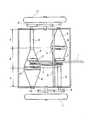
図1に示すように、ペダルからの駆動力は、ベルトまたはチェーン1(以下、ベルトと呼ぶ。)から駆動摩擦ローラ2,2'に同時に伝えられる。駆動摩擦ローラ2,2'はマウント7に支承されていて、これらは一体となってガイド8に沿って摺動する。被動側の摩擦車の構成は、正転用の円錐型摩擦車3、3'とこれと一体の円筒型摩擦車5、5'及び逆転用の円錐型摩擦車4、4'とからなる。円筒型摩擦車5,5'の先には歯車9,9'が固定されていて、歯車10,10'を介して左右の車輪11,11'に動力が伝わる。図2に示されているが、円錐型摩擦車3、3'には内歯歯車13、13'が一体形成されており、円錐型摩擦車4と一体の太陽歯車14とフローティングホイール6,6'の固定軸に遊嵌された遊星歯車12とで単純遊星歯車機構を構成する。円錐型摩擦車4とフローティングホイール6,6'との間には一方向クラッチ15が配置されている。The first embodiment will be described below. The term “speed ratio” is used to mean (output side rotational speed) / (input side rotational speed).
As shown in FIG. 1, the driving force from the pedal is simultaneously transmitted from the belt or chain 1 (hereinafter referred to as a belt) to the driving
次に上記駆動旋回装置の作動を説明する。B領域では左右の車輪11,11'が共に前進回転する領域である。A領域では左車輪11'は前進回転し右車輪11は後進回転する領域である。C領域は右車輪11が前進回転し、左車輪11'が後進回転する領域である。A領域とB領域との境界領域は左車輪11'が前進回転し、右車輪11が停止する領域である。B領域とC領域との境界領域は右車輪11が前進回転し、左車輪11'が停止する領域である。 Next, the operation of the drive turning device will be described. In the region B, the left and right wheels 11 and 11 ′ are both rotated forward. In the area A, the left wheel 11 ′ rotates forward and the right wheel 11 rotates backward. The area C is an area in which the right wheel 11 rotates forward and the left wheel 11 ′ rotates backward. A boundary region between the A region and the B region is a region where the left wheel 11 ′ rotates forward and the right wheel 11 stops. The boundary area between the B area and the C area is an area where the right wheel 11 rotates forward and the left wheel 11 ′ stops.
図1の状態において、ベルト1から駆動摩擦ローラ2,2'に伝えられた動力は正転伝達用の円錐型摩擦車3,3'に回転を与え、円錐型摩擦車3,3'と一体の円筒型摩擦車5,5'から歯車9,9'と歯車10,10'を介して、左右の車輪11,11'に伝えられる。円錐型摩擦車3,3'の変速比は共に等しい位置に配置されているので、左右の車輪11,11'は等しい速度で前進回転し、この結果車椅子は直進する。 In the state shown in FIG. 1, the power transmitted from the belt 1 to the
マウント7をガイド8に沿ってB領域で左の車輪11'方向に移動させて行くと、円錐型摩擦車3'と駆動摩擦ローラ2'との変速比は高くなってゆき、円錐型摩擦車3と駆動摩擦ローラ2との変速比は低くなってゆくので、左の車輪11'の回転速度は上昇し、右の車輪11の回転速度は低下する。これにより、車椅子は左右の車輪11,11'の前進回転速度に応じた特性で右方向に旋回することとなる。変速比の差が大きくなるほど旋回半径は小さくなって、小回り状態となる。 When the
次に、マウント7をガイド8に沿ってAとBとの境界領域に移動した時の動作を説明する。この状態では、駆動摩擦ローラ2はフローティングホイール6に回転を伝え、駆動摩擦ローラ2'は円筒型摩擦車5'に回転を伝えるようになる。そうすると、円筒型摩擦車5'は最も高い変速比で駆動されることとなるが、フローティングホイール6に与えられた回転は逆転用の円錐型摩擦車4を空回転させるのみで、正転用の円錐型摩擦車3に回転力を取出すことができないので、右車輪11は停止状態になる。この状態では、車椅子は右車輪11を中心にして右旋回をすることとなり、いわゆる信地旋回状態となる。 Next, the operation when the
更にマウント7をガイド8に沿って移動させてA領域に達すると、駆動摩擦ローラ2'が円筒型摩擦車5'に回転を伝えることに変わりはないが、駆動摩擦ローラ2は逆転用の円錐型摩擦車4を回転するようになる。そうすると、一方向クラッチ15の作用で、逆転用円錐型摩擦車4と一体の太陽歯車14とフローティングホイール6とは互いに逆方向の回転が許容されるから、フローティングホイール6の固定軸に遊嵌された遊星歯車12が太陽歯車14上を公転しながら自転して、内歯歯車13を逆方向に回転させるようになる。内歯歯車13は正転用の円錐型摩擦車3に一体的に設けられているから、正転用の円錐型摩擦車3は逆転することになる。そうすると、左車輪11'は前進回転を行う一方で、右車輪11は後進回転をすることとなる。左車輪11'の前進回転速度と、右車輪11の後進回転速度とを等しく設定すれば、車椅子は、超信地旋回を行うことが可能である。 Further, when the
B領域からC領域に入ると、今度は左車輪11'が停止状態からやがて後進回転に移行し、この間右車輪11は前進回転となるから、車椅子は左旋回することができる。作動は右旋回とほぼ同様であるから、説明は省略する。 When entering the C region from the B region, the left wheel 11 'is now shifted from the stopped state to the reverse rotation, and during this time, the right wheel 11 is rotated forward, so that the wheelchair can turn left. Since the operation is almost the same as that of turning right, the description is omitted.
第2の実施例につき以下に説明する。基本構成は第1実施例のものと大きく違いはしないが、単純遊星歯車装置の構成に相違点がある。第1実施例のものは遊星歯車12をフローティングホイール6と一体の固定軸に遊嵌させる構成を採っているので、フローティングホイール6が遊星キャリアの役割を兼用している。したがって、所望の作用を得るために、逆転用の円錐摩擦車4とフローティングホイール6との間に一方向クラッチ15を介在させているが、第2実施例のものは、アングル16と一体の固定軸に遊星歯車12を遊嵌し、かつ、アングル16を外部の固定部に一体化する構成としているので、アングル16に固定型遊星キャリアの役割を担わせている。更に、フローティングホイール6は逆転用の円錐型摩擦車4と互いに遊合関係にある。この構成によれば、一方向クラッチ15を必要としない。 The second embodiment will be described below. Although the basic configuration is not significantly different from that of the first embodiment, there is a difference in the configuration of the simple planetary gear device. In the first embodiment, the
次に上記駆動旋回装置の作動を説明する。B領域では左右の車輪11,11'が共に前進回転する領域である。A領域では左車輪11'は前進回転し右車輪11は後進回転する領域である。C領域は右車輪11が前進回転し、左車輪11'が後進回転する領域である。A領域とB領域との境界領域は左車輪11'が前進回転し、右車輪11が停止する領域である。B領域とC領域との境界領域は右車輪11が前進回転し、左車輪11'が停止する領域である。 Next, the operation of the drive turning device will be described. In the region B, the left and right wheels 11 and 11 ′ are both rotated forward. In the area A, the left wheel 11 ′ rotates forward and the right wheel 11 rotates backward. The area C is an area in which the right wheel 11 rotates forward and the left wheel 11 ′ rotates backward. A boundary region between the A region and the B region is a region where the left wheel 11 ′ rotates forward and the right wheel 11 stops. The boundary area between the B area and the C area is an area where the right wheel 11 rotates forward and the left wheel 11 ′ stops.
図1の状態において、ベルト1から駆動摩擦ローラ2,2'に伝えられた動力は正転伝達用の円錐型摩擦車3,3'に回転を与え、円錐型摩擦車3,3'と一体の円筒型摩擦車5,5'から歯車9,9'と歯車10,10'を介して、左右の車輪11,11'に伝えられる。円錐型摩擦車3,3'の変速比は共に等しい位置に配置されているので、左右の車輪11,11'は等しい速度で前進回転し、この結果車椅子は直進する。 In the state shown in FIG. 1, the power transmitted from the belt 1 to the
マウント7をガイド8に沿ってB領域で左の車輪11'方向に移動させて行くと、円錐型摩擦車3'と駆動摩擦ローラ2'との変速比は高くなってゆき、円錐型摩擦車3と駆動摩擦ローラ2との変速比は低くなってゆくので、左の車輪11'の回転速度は上昇し、右の車輪11の回転速度は低下する。これにより、車椅子は左右の車輪11,11'の前進回転速度に応じた特性で右方向に旋回することとなる。変速比の差が大きくなるほど旋回半径は小さくなって、小回り状態となる。 When the
次に、マウント7をガイド8に沿ってAとBとの境界領域に移動した時の動作を説明する。この状態では、駆動摩擦ローラ2はフローティングホイール6に回転を伝え、駆動摩擦ローラ2'は円筒型摩擦車5'に回転を伝えるようになる。そうすると、円筒型摩擦車5'は最も高い変速比で駆動されることとなるが、フローティングホイール6に与えられた回転はフローティングホイール6を空回転させるのみで、正転用の円錐型摩擦車3に回転力を取出すことができないので、右車輪11は停止状態になる。この状態では、車椅子は右車輪11を中心にして右旋回をすることとなり、いわゆる信地旋回状態となる。 Next, the operation when the
更にマウント7をガイド8に沿って移動させてA領域に達すると、駆動摩擦ローラ2'が円筒型摩擦車5'に回転を伝えることに変わりはないが、駆動摩擦ローラ2は逆転用の円錐型摩擦車4を回転するようになる。そうすると、逆転用円錐型摩擦車4と一体の太陽歯車14の回転は、外部の固定部と一体のアングル16の固定軸に遊嵌された遊星歯車12を介して、内歯歯車13を太陽歯車14とは逆方向に回転させるようになる。内歯歯車13は正転用の円錐型摩擦車3に一体的に設けられているから、正転用の円錐型摩擦車3は逆転することになる。そうすると、左車輪11'は前進回転を行う一方で、右車輪11は後進回転をすることとなる。左車輪11'の前進回転速度と、右車輪11の後進回転速度とを等しく設定すれば、車椅子は、超信地旋回を行うことが可能である。 Further, when the
B領域からC領域に入ると、今度は左車輪11'が停止状態を経て後進回転に移行し、この間右車輪11は前進回転領域にあるから、車椅子は左旋回することができる。作動は右旋回とほぼ同様であるから、説明は省略する。 When entering the C area from the B area, the left wheel 11 'is now in a stopped state and then shifts to the reverse rotation. During this time, the right wheel 11 is in the forward rotation area, so the wheelchair can turn left. Since the operation is almost the same as that of turning right, the description is omitted.
以下においては参考例について説明する。図4において、入力軸30に伝えられた動力は右側の無段変速機31と左側の無段変速機32とに同じ速度で伝えられ、無段変速機31,32で変速された出力が右車輪33と左車輪34とに伝えられる。無段変速機31,32は変速リング35,36を軸線方向に移動させることにより、正転領域からゼロ変速領域を経て逆転領域まで無段変速を行うことができるのである。図4において、変速リング35,36は無段変速機31,32の正転領域で相等しい変速比が得られるようにセットされており、ハンドル38は中立位置にある。この状態は車椅子の直進状態を示しており、右車輪33と左車輪34とは共に同じ速度で前進方向に回転する。A reference example will be described below. In FIG. 4, the power transmitted to the
ハンドル38を右に切り始めると、操作ロッド37により変速リング35と変速リング36とは揃って右方向に移動する。これにより右側の無段変速機31の変速比は小さくなり、逆に左側の無段変速機32の変速比は大きくなるから、右車輪33の前進速度は低下し、一方左車輪34の前進速度が増大するので、車椅子は大きな旋回半径で右旋回を始める。ハンドル38の切り角が大きくなるにつれて、旋回半径は徐々に小さくなって行く。 When the handle 38 starts to be turned to the right, the transmission ring 35 and the
更にハンドルを切ると、右側の無段変速機31はゼロ変速状態となり、左側の無段変速機32の変速比はより大きくなって、車椅子は停止した右車輪を中心として信地旋回をおこなう。 When the steering wheel is further turned off, the right continuously
更にハンドルを切ると、右側の無段変速機31は逆転領域に入るので、右車輪33は後進回転を始めるから、信地旋回状態よりも超信地旋回状態に近づくようになる。ハンドル38を一杯に切れば、右側の無段変速機31の逆転変速比も大きくなり、ほぼ超信地旋回に近い小回りを得ることができる。 When the steering wheel is further turned, the right continuously
以上の説明は、足踏み駆動を継続しつつハンドル38の操舵角を徐々に変更する例を述べたものであるが、足踏み駆動と操舵とは手と足で独立して行うことができるから、例えば、ハンドル38を信地旋回状態にセットした後、足踏み駆動により旋回のみを行うことも可能である。勿論、停止状態からその他の旋回特性を得ることも可能なのである。この発明は脳卒中、脊髄損傷およびその他の外傷や疾患を原因とする歩行障害者のリハビリと移動能力獲得のための足踏み式車椅子を念頭に置いたものであるが、電動式の車椅子に摘要したとしても、その優れた操舵性が損なわれるものでは一切ない。 The above description describes an example in which the steering angle of the handle 38 is gradually changed while continuing the stepping drive. However, since the stepping drive and the steering can be performed independently by hand and foot, for example, It is also possible to perform only turning by stepping after the handle 38 is set to the belief turning state. Of course, other turning characteristics can be obtained from the stop state. This invention is intended for a stepped wheelchair for rehabilitation and acquisition of mobility ability for people with gait disabilities caused by stroke, spinal cord injury and other traumas and diseases. However, its excellent steering performance is not impaired at all.
次に、図5に基づいて無段変速機の詳細を説明する。この無段変速機は周知であって、入力軸21に固着された摩擦車23は円錐形ローラ26と一体の凹形断面の伝動面27と摩擦接触している。一方、出力軸22側に配置された軌道リング24が円錐形ローラ26の底面に摩擦接触している。円錐形ローラ26はキャリア28に支承されて自転しながら公転できるようになっており、円錐形ローラ26の円錐面には変速リング25が摩擦接触している。変速リング25を軸線方向に動かすことによって軌道リング24に得られた変速回転は、カム形式の圧接力発生装置を経て出力軸22に取出される。 Next, the details of the continuously variable transmission will be described with reference to FIG. This continuously variable transmission is well known, and the
本発明は、脳卒中、脊髄損傷およびその他の外傷や疾患を原因とする歩行障害者のリハビリと移動能力獲得のための足踏み式車椅子として有効である。また電動式の車椅子への適用も、その優れた操舵性からして十分に期待できるものである。 INDUSTRIAL APPLICABILITY The present invention is effective as a stepping wheelchair for rehabilitation and acquisition of mobility ability for persons with gait disorders caused by stroke, spinal cord injury and other traumas and diseases. Application to electric wheelchairs can be sufficiently expected from its excellent steering performance.
1 ベルトまたはチェーン
2,2' 駆動摩擦ローラ
3,3' 正転伝達用の円錐型摩擦車
4,4' 逆転伝達用の円錐型摩擦車
5,5' 円筒型摩擦車
6,6' フローティングホイール
7 マウント
8 ガイド
9,9' 歯車
10,10' 歯車
11,11' 車輪
12 遊星歯車
13 内歯歯車
14 太陽歯車
15 一方向クラッチ
16 アングル
21 入力軸
22 出力軸
23 入力軸上の摩擦車
24 軌道リング
25 変速リング
26 円錐型ローラ
27 凹断面形の伝動面
28 キャリア
29 操作軸
30 入力軸
31 右側の無段変速機
32 左側の無段変速機
33 右車輪
34 左車輪
35 右側の無段変速機の変速リング
36 左側の無段変速機の変速リング
37 操作ロッドDESCRIPTION OF SYMBOLS 1 Belt or
Claims (5)
Translated fromJapanesePriority Applications (1)
| Application Number | Priority Date | Filing Date | Title |
|---|---|---|---|
| JP2008239633AJP4603607B2 (en) | 2008-09-18 | 2008-09-18 | Wheel drive wheel drive swivel |
Applications Claiming Priority (1)
| Application Number | Priority Date | Filing Date | Title |
|---|---|---|---|
| JP2008239633AJP4603607B2 (en) | 2008-09-18 | 2008-09-18 | Wheel drive wheel drive swivel |
Publications (2)
| Publication Number | Publication Date |
|---|---|
| JP2010069005A JP2010069005A (en) | 2010-04-02 |
| JP4603607B2true JP4603607B2 (en) | 2010-12-22 |
Family
ID=42201339
Family Applications (1)
| Application Number | Title | Priority Date | Filing Date |
|---|---|---|---|
| JP2008239633AActiveJP4603607B2 (en) | 2008-09-18 | 2008-09-18 | Wheel drive wheel drive swivel |
Country Status (1)
| Country | Link |
|---|---|
| JP (1) | JP4603607B2 (en) |
Cited By (1)
| Publication number | Priority date | Publication date | Assignee | Title |
|---|---|---|---|---|
| CN102943856A (en)* | 2012-10-30 | 2013-02-27 | 任孝忠 | Bipyramidal synchronous rotation speed change device |
Families Citing this family (42)
| Publication number | Priority date | Publication date | Assignee | Title |
|---|---|---|---|---|
| US7011600B2 (en) | 2003-02-28 | 2006-03-14 | Fallbrook Technologies Inc. | Continuously variable transmission |
| WO2006041718A2 (en) | 2004-10-05 | 2006-04-20 | Fallbrook Technologies, Inc. | Continuously variable transmission |
| WO2007070167A2 (en) | 2005-10-28 | 2007-06-21 | Fallbrook Technologies Inc. | Electromotive drives |
| PL1954959T3 (en) | 2005-11-22 | 2013-10-31 | Fallbrook Ip Co Llc | Continuously variable transmission |
| CN102221073B (en) | 2005-12-09 | 2013-03-27 | 福博科技术公司 | Continuously variable transmission |
| EP1811202A1 (en) | 2005-12-30 | 2007-07-25 | Fallbrook Technologies, Inc. | A continuously variable gear transmission |
| US7882762B2 (en) | 2006-01-30 | 2011-02-08 | Fallbrook Technologies Inc. | System for manipulating a continuously variable transmission |
| WO2007106874A2 (en)* | 2006-03-14 | 2007-09-20 | Autocraft Industries, Inc. | Improved wheelchair |
| CN102269055B (en) | 2006-06-26 | 2013-08-28 | 福博科技术公司 | Continuously variable transmission |
| PL2089642T3 (en) | 2006-11-08 | 2013-09-30 | Fallbrook Ip Co Llc | Clamping force generator |
| EP2125469A2 (en) | 2007-02-01 | 2009-12-02 | Fallbrook Technologies Inc. | System and methods for control of transmission and/or prime mover |
| US20100093479A1 (en) | 2007-02-12 | 2010-04-15 | Fallbrook Technologies Inc. | Continuously variable transmissions and methods therefor |
| TWI461615B (en) | 2007-02-16 | 2014-11-21 | Fallbrook Ip Co Llc | Infinitely variable transmissions, continuously variable transmissions, methods, assemblies, subassemblies, and components therefor |
| EP2142826B1 (en) | 2007-04-24 | 2015-10-28 | Fallbrook Intellectual Property Company LLC | Electric traction drives |
| US8641577B2 (en) | 2007-06-11 | 2014-02-04 | Fallbrook Intellectual Property Company Llc | Continuously variable transmission |
| CN103697120B (en) | 2007-07-05 | 2017-04-12 | 福博科技术公司 | Continuously variable transmission |
| CN103939602B (en) | 2007-11-16 | 2016-12-07 | 福博科知识产权有限责任公司 | Controllers for variable speed drives |
| US8321097B2 (en) | 2007-12-21 | 2012-11-27 | Fallbrook Intellectual Property Company Llc | Automatic transmissions and methods therefor |
| US8313405B2 (en) | 2008-02-29 | 2012-11-20 | Fallbrook Intellectual Property Company Llc | Continuously and/or infinitely variable transmissions and methods therefor |
| US8317651B2 (en) | 2008-05-07 | 2012-11-27 | Fallbrook Intellectual Property Company Llc | Assemblies and methods for clamping force generation |
| CN102112778B (en) | 2008-06-06 | 2013-10-16 | 福博科技术公司 | Infinitely variable transmission, continuously variable transmission, methods, assemblies, subassemblies and components therefor |
| EP2304272B1 (en) | 2008-06-23 | 2017-03-08 | Fallbrook Intellectual Property Company LLC | Continuously variable transmission |
| CA2732668C (en) | 2008-08-05 | 2017-11-14 | Fallbrook Technologies Inc. | Methods for control of transmission and prime mover |
| US8469856B2 (en) | 2008-08-26 | 2013-06-25 | Fallbrook Intellectual Property Company Llc | Continuously variable transmission |
| US8167759B2 (en) | 2008-10-14 | 2012-05-01 | Fallbrook Technologies Inc. | Continuously variable transmission |
| ES2439647T3 (en) | 2009-04-16 | 2014-01-24 | Fallbrook Intellectual Property Company Llc | Stator set and speed change mechanism for a continuously variable transmission |
| US8512195B2 (en) | 2010-03-03 | 2013-08-20 | Fallbrook Intellectual Property Company Llc | Infinitely variable transmissions, continuously variable transmissions, methods, assemblies, subassemblies, and components therefor |
| JP2012020724A (en)* | 2010-06-14 | 2012-02-02 | Jtekt Corp | Tricycle |
| JP2012101577A (en)* | 2010-11-05 | 2012-05-31 | Jtekt Corp | Steering device of vehicle |
| US8888643B2 (en) | 2010-11-10 | 2014-11-18 | Fallbrook Intellectual Property Company Llc | Continuously variable transmission |
| AU2012240435B2 (en) | 2011-04-04 | 2016-04-28 | Fallbrook Intellectual Property Company Llc | Auxiliary power unit having a continuously variable transmission |
| CN104302949B (en) | 2012-01-23 | 2017-05-03 | 福博科知识产权有限责任公司 | Infinitely variable continuously variable transmission, continuously variable continuously variable transmission, method, assembly, subassembly, and parts thereof |
| CN102670359B (en)* | 2012-05-11 | 2015-01-07 | 北京电子科技职业学院 | Wheel chair |
| KR102433297B1 (en) | 2013-04-19 | 2022-08-16 | 폴브룩 인텔렉츄얼 프로퍼티 컴퍼니 엘엘씨 | Continuously variable transmission |
| CN104989794B (en)* | 2015-07-10 | 2017-09-29 | 徐丹 | A sliding continuously variable transmission mechanism suitable for non-collinear transmission |
| US10047861B2 (en) | 2016-01-15 | 2018-08-14 | Fallbrook Intellectual Property Company Llc | Systems and methods for controlling rollback in continuously variable transmissions |
| KR102364407B1 (en) | 2016-03-18 | 2022-02-16 | 폴브룩 인텔렉츄얼 프로퍼티 컴퍼니 엘엘씨 | continuously variable transmission system and method |
| US10023266B2 (en) | 2016-05-11 | 2018-07-17 | Fallbrook Intellectual Property Company Llc | Systems and methods for automatic configuration and automatic calibration of continuously variable transmissions and bicycles having continuously variable transmissions |
| KR101705291B1 (en)* | 2016-10-19 | 2017-02-09 | 문현덕 | Driving assistant device for a wheelchair on slope way |
| US11215268B2 (en) | 2018-11-06 | 2022-01-04 | Fallbrook Intellectual Property Company Llc | Continuously variable transmissions, synchronous shifting, twin countershafts and methods for control of same |
| WO2020176392A1 (en) | 2019-02-26 | 2020-09-03 | Fallbrook Intellectual Property Company Llc | Reversible variable drives and systems and methods for control in forward and reverse directions |
| CN110001391B (en)* | 2019-04-26 | 2024-04-02 | 大连聪迅网络科技有限公司 | Multi-wheel differential system |
Family Cites Families (8)
| Publication number | Priority date | Publication date | Assignee | Title |
|---|---|---|---|---|
| JPS5856973A (en)* | 1981-09-30 | 1983-04-04 | Mitsubishi Agricult Mach Co Ltd | Superconfidence spot turning device in traveling equipment provided with stepless transmission |
| JPH0774667B2 (en)* | 1986-09-16 | 1995-08-09 | シンポ工業株式会社 | Friction continuously variable transmission for work vehicle |
| JPH0441149U (en)* | 1990-08-03 | 1992-04-08 | ||
| JP3039588B2 (en)* | 1993-04-09 | 2000-05-08 | 小橋工業株式会社 | Differential transmission |
| JPH1149023A (en)* | 1997-08-01 | 1999-02-23 | Kubota Corp | Working machine swivel |
| JP4195238B2 (en)* | 2002-05-24 | 2008-12-10 | 康延 半田 | Front wheel drive wheelchair |
| JP2004141452A (en)* | 2002-10-25 | 2004-05-20 | Tada Mokko Seisakusho:Kk | Single-hand operation type wheelchair |
| JP2007045220A (en)* | 2005-08-08 | 2007-02-22 | Nsk Ltd | Vehicle drive device |
- 2008
- 2008-09-18JPJP2008239633Apatent/JP4603607B2/enactiveActive
Cited By (1)
| Publication number | Priority date | Publication date | Assignee | Title |
|---|---|---|---|---|
| CN102943856A (en)* | 2012-10-30 | 2013-02-27 | 任孝忠 | Bipyramidal synchronous rotation speed change device |
Also Published As
| Publication number | Publication date |
|---|---|
| JP2010069005A (en) | 2010-04-02 |
Similar Documents
| Publication | Publication Date | Title |
|---|---|---|
| JP4603607B2 (en) | Wheel drive wheel drive swivel | |
| CA2522685C (en) | Continuously variable transmission | |
| CN102785716B (en) | Special-shaped wheel and caterpillar track combined walking mechanism | |
| US7770674B2 (en) | Wheel chair | |
| JP5437817B2 (en) | Continuously variable transmission | |
| US11685436B2 (en) | Vehicle drive transmission and electrically assisted steering system | |
| KR20040026114A (en) | Wheelchair with forced driven front caterpillar wheels | |
| EP2752179B1 (en) | Wheelchair provided with feet | |
| CN110382341A (en) | Multistage speed-changing bicycle | |
| JP4195238B2 (en) | Front wheel drive wheelchair | |
| RU2554715C2 (en) | Planetary coordinating gear box | |
| NL1022934C2 (en) | Forward-reverse control device. | |
| JP2019116934A (en) | Driving device for vehicle travel | |
| CN2849338Y (en) | Mechanical differential reversing arrangement | |
| CN108619737A (en) | Full landform engineering vehicle model | |
| SE1450512A1 (en) | Gear unit for a wheelchair wheel | |
| CN1017493B (en) | wheelchair | |
| RU2240246C1 (en) | Self-propelled vehicle steering variable-speed drive | |
| EP0170327B1 (en) | Driving system for a cross-country vehicle | |
| KR100380319B1 (en) | A drive system for a wheel chair using the speed reducer | |
| JP5063962B2 (en) | Mobile body with legs and wheels | |
| KR102684564B1 (en) | Driving device for wheelchair | |
| CN222329465U (en) | Dual-motor transmission system for tracked vehicle | |
| CN104015868B (en) | A kind of bicycle linear speed regulating device | |
| KR200340225Y1 (en) | Wheel chair have the steering and working equipment |
Legal Events
| Date | Code | Title | Description |
|---|---|---|---|
| A621 | Written request for application examination | Free format text:JAPANESE INTERMEDIATE CODE: A621 Effective date:20100205 | |
| A871 | Explanation of circumstances concerning accelerated examination | Free format text:JAPANESE INTERMEDIATE CODE: A871 Effective date:20100205 | |
| A975 | Report on accelerated examination | Free format text:JAPANESE INTERMEDIATE CODE: A971005 Effective date:20100316 | |
| A521 | Request for written amendment filed | Free format text:JAPANESE INTERMEDIATE CODE: A523 Effective date:20100416 | |
| A131 | Notification of reasons for refusal | Free format text:JAPANESE INTERMEDIATE CODE: A131 Effective date:20100608 | |
| A521 | Request for written amendment filed | Free format text:JAPANESE INTERMEDIATE CODE: A821 Effective date:20100720 | |
| RD02 | Notification of acceptance of power of attorney | Free format text:JAPANESE INTERMEDIATE CODE: A7422 Effective date:20100720 | |
| A521 | Request for written amendment filed | Free format text:JAPANESE INTERMEDIATE CODE: A821 Effective date:20100720 | |
| A521 | Request for written amendment filed | Free format text:JAPANESE INTERMEDIATE CODE: A523 Effective date:20100809 | |
| TRDD | Decision of grant or rejection written | ||
| A01 | Written decision to grant a patent or to grant a registration (utility model) | Free format text:JAPANESE INTERMEDIATE CODE: A01 Effective date:20100907 | |
| A01 | Written decision to grant a patent or to grant a registration (utility model) | Free format text:JAPANESE INTERMEDIATE CODE: A01 | |
| A61 | First payment of annual fees (during grant procedure) | Free format text:JAPANESE INTERMEDIATE CODE: A61 Effective date:20101001 | |
| FPAY | Renewal fee payment (event date is renewal date of database) | Free format text:PAYMENT UNTIL: 20131008 Year of fee payment:3 | |
| R150 | Certificate of patent or registration of utility model | Ref document number:4603607 Country of ref document:JP Free format text:JAPANESE INTERMEDIATE CODE: R150 Free format text:JAPANESE INTERMEDIATE CODE: R150 | |
| R250 | Receipt of annual fees | Free format text:JAPANESE INTERMEDIATE CODE: R250 | |
| R250 | Receipt of annual fees | Free format text:JAPANESE INTERMEDIATE CODE: R250 | |
| R250 | Receipt of annual fees | Free format text:JAPANESE INTERMEDIATE CODE: R250 | |
| R250 | Receipt of annual fees | Free format text:JAPANESE INTERMEDIATE CODE: R250 | |
| R250 | Receipt of annual fees | Free format text:JAPANESE INTERMEDIATE CODE: R250 | |
| R250 | Receipt of annual fees | Free format text:JAPANESE INTERMEDIATE CODE: R250 | |
| R250 | Receipt of annual fees | Free format text:JAPANESE INTERMEDIATE CODE: R250 | |
| R250 | Receipt of annual fees | Free format text:JAPANESE INTERMEDIATE CODE: R250 | |
| R250 | Receipt of annual fees | Free format text:JAPANESE INTERMEDIATE CODE: R250 |