JP4601868B2 - Networked monitoring / control system and method - Google Patents
Networked monitoring / control system and methodDownload PDFInfo
- Publication number
- JP4601868B2 JP4601868B2JP2001194713AJP2001194713AJP4601868B2JP 4601868 B2JP4601868 B2JP 4601868B2JP 2001194713 AJP2001194713 AJP 2001194713AJP 2001194713 AJP2001194713 AJP 2001194713AJP 4601868 B2JP4601868 B2JP 4601868B2
- Authority
- JP
- Japan
- Prior art keywords
- control system
- monitoring
- video signal
- digital video
- compressed
- Prior art date
- Legal status (The legal status is an assumption and is not a legal conclusion. Google has not performed a legal analysis and makes no representation as to the accuracy of the status listed.)
- Expired - Lifetime
Links
Images


Classifications
- G—PHYSICS
- G06—COMPUTING OR CALCULATING; COUNTING
- G06V—IMAGE OR VIDEO RECOGNITION OR UNDERSTANDING
- G06V20/00—Scenes; Scene-specific elements
- G06V20/50—Context or environment of the image
- G06V20/52—Surveillance or monitoring of activities, e.g. for recognising suspicious objects
- G—PHYSICS
- G06—COMPUTING OR CALCULATING; COUNTING
- G06F—ELECTRIC DIGITAL DATA PROCESSING
- G06F16/00—Information retrieval; Database structures therefor; File system structures therefor
- G06F16/70—Information retrieval; Database structures therefor; File system structures therefor of video data
- G06F16/73—Querying
- G06F16/738—Presentation of query results
- G06F16/739—Presentation of query results in form of a video summary, e.g. the video summary being a video sequence, a composite still image or having synthesized frames
- G—PHYSICS
- G06—COMPUTING OR CALCULATING; COUNTING
- G06F—ELECTRIC DIGITAL DATA PROCESSING
- G06F16/00—Information retrieval; Database structures therefor; File system structures therefor
- G06F16/70—Information retrieval; Database structures therefor; File system structures therefor of video data
- G06F16/78—Retrieval characterised by using metadata, e.g. metadata not derived from the content or metadata generated manually
- G06F16/783—Retrieval characterised by using metadata, e.g. metadata not derived from the content or metadata generated manually using metadata automatically derived from the content
- G06F16/7847—Retrieval characterised by using metadata, e.g. metadata not derived from the content or metadata generated manually using metadata automatically derived from the content using low-level visual features of the video content
- G06F16/7854—Retrieval characterised by using metadata, e.g. metadata not derived from the content or metadata generated manually using metadata automatically derived from the content using low-level visual features of the video content using shape
- G—PHYSICS
- G06—COMPUTING OR CALCULATING; COUNTING
- G06F—ELECTRIC DIGITAL DATA PROCESSING
- G06F16/00—Information retrieval; Database structures therefor; File system structures therefor
- G06F16/70—Information retrieval; Database structures therefor; File system structures therefor of video data
- G06F16/78—Retrieval characterised by using metadata, e.g. metadata not derived from the content or metadata generated manually
- G06F16/783—Retrieval characterised by using metadata, e.g. metadata not derived from the content or metadata generated manually using metadata automatically derived from the content
- G06F16/7847—Retrieval characterised by using metadata, e.g. metadata not derived from the content or metadata generated manually using metadata automatically derived from the content using low-level visual features of the video content
- G06F16/786—Retrieval characterised by using metadata, e.g. metadata not derived from the content or metadata generated manually using metadata automatically derived from the content using low-level visual features of the video content using motion, e.g. object motion or camera motion
- G—PHYSICS
- G06—COMPUTING OR CALCULATING; COUNTING
- G06F—ELECTRIC DIGITAL DATA PROCESSING
- G06F16/00—Information retrieval; Database structures therefor; File system structures therefor
- G06F16/70—Information retrieval; Database structures therefor; File system structures therefor of video data
- G06F16/78—Retrieval characterised by using metadata, e.g. metadata not derived from the content or metadata generated manually
- G06F16/783—Retrieval characterised by using metadata, e.g. metadata not derived from the content or metadata generated manually using metadata automatically derived from the content
- G06F16/7847—Retrieval characterised by using metadata, e.g. metadata not derived from the content or metadata generated manually using metadata automatically derived from the content using low-level visual features of the video content
- G06F16/7864—Retrieval characterised by using metadata, e.g. metadata not derived from the content or metadata generated manually using metadata automatically derived from the content using low-level visual features of the video content using domain-transform features, e.g. DCT or wavelet transform coefficients
- H—ELECTRICITY
- H04—ELECTRIC COMMUNICATION TECHNIQUE
- H04N—PICTORIAL COMMUNICATION, e.g. TELEVISION
- H04N21/00—Selective content distribution, e.g. interactive television or video on demand [VOD]
- H04N21/20—Servers specifically adapted for the distribution of content, e.g. VOD servers; Operations thereof
- H04N21/23—Processing of content or additional data; Elementary server operations; Server middleware
- H04N21/234—Processing of video elementary streams, e.g. splicing of video streams or manipulating encoded video stream scene graphs
- H04N21/23418—Processing of video elementary streams, e.g. splicing of video streams or manipulating encoded video stream scene graphs involving operations for analysing video streams, e.g. detecting features or characteristics
- H—ELECTRICITY
- H04—ELECTRIC COMMUNICATION TECHNIQUE
- H04N—PICTORIAL COMMUNICATION, e.g. TELEVISION
- H04N21/00—Selective content distribution, e.g. interactive television or video on demand [VOD]
- H04N21/20—Servers specifically adapted for the distribution of content, e.g. VOD servers; Operations thereof
- H04N21/23—Processing of content or additional data; Elementary server operations; Server middleware
- H04N21/238—Interfacing the downstream path of the transmission network, e.g. adapting the transmission rate of a video stream to network bandwidth; Processing of multiplex streams
- H04N21/2389—Multiplex stream processing, e.g. multiplex stream encrypting
- H—ELECTRICITY
- H04—ELECTRIC COMMUNICATION TECHNIQUE
- H04N—PICTORIAL COMMUNICATION, e.g. TELEVISION
- H04N21/00—Selective content distribution, e.g. interactive television or video on demand [VOD]
- H04N21/40—Client devices specifically adapted for the reception of or interaction with content, e.g. set-top-box [STB]; Operations thereof
- H04N21/43—Processing of content or additional data, e.g. demultiplexing additional data from a digital video stream; Elementary client operations, e.g. monitoring of home network or synchronising decoder's clock; Client middleware
- H04N21/438—Interfacing the downstream path of the transmission network originating from a server, e.g. retrieving encoded video stream packets from an IP network
- H04N21/4385—Multiplex stream processing, e.g. multiplex stream decrypting
- H—ELECTRICITY
- H04—ELECTRIC COMMUNICATION TECHNIQUE
- H04N—PICTORIAL COMMUNICATION, e.g. TELEVISION
- H04N21/00—Selective content distribution, e.g. interactive television or video on demand [VOD]
- H04N21/80—Generation or processing of content or additional data by content creator independently of the distribution process; Content per se
- H04N21/83—Generation or processing of protective or descriptive data associated with content; Content structuring
- H04N21/84—Generation or processing of descriptive data, e.g. content descriptors
- H04N21/8405—Generation or processing of descriptive data, e.g. content descriptors represented by keywords
- H—ELECTRICITY
- H04—ELECTRIC COMMUNICATION TECHNIQUE
- H04N—PICTORIAL COMMUNICATION, e.g. TELEVISION
- H04N7/00—Television systems
- H04N7/18—Closed-circuit television [CCTV] systems, i.e. systems in which the video signal is not broadcast
- H04N7/181—Closed-circuit television [CCTV] systems, i.e. systems in which the video signal is not broadcast for receiving images from a plurality of remote sources
- H—ELECTRICITY
- H04—ELECTRIC COMMUNICATION TECHNIQUE
- H04N—PICTORIAL COMMUNICATION, e.g. TELEVISION
- H04N19/00—Methods or arrangements for coding, decoding, compressing or decompressing digital video signals
- H04N19/46—Embedding additional information in the video signal during the compression process
- H—ELECTRICITY
- H04—ELECTRIC COMMUNICATION TECHNIQUE
- H04N—PICTORIAL COMMUNICATION, e.g. TELEVISION
- H04N19/00—Methods or arrangements for coding, decoding, compressing or decompressing digital video signals
- H04N19/48—Methods or arrangements for coding, decoding, compressing or decompressing digital video signals using compressed domain processing techniques other than decoding, e.g. modification of transform coefficients, variable length coding [VLC] data or run-length data
- H—ELECTRICITY
- H04—ELECTRIC COMMUNICATION TECHNIQUE
- H04N—PICTORIAL COMMUNICATION, e.g. TELEVISION
- H04N19/00—Methods or arrangements for coding, decoding, compressing or decompressing digital video signals
- H04N19/50—Methods or arrangements for coding, decoding, compressing or decompressing digital video signals using predictive coding
- H04N19/503—Methods or arrangements for coding, decoding, compressing or decompressing digital video signals using predictive coding involving temporal prediction
- H04N19/51—Motion estimation or motion compensation
- H—ELECTRICITY
- H04—ELECTRIC COMMUNICATION TECHNIQUE
- H04N—PICTORIAL COMMUNICATION, e.g. TELEVISION
- H04N19/00—Methods or arrangements for coding, decoding, compressing or decompressing digital video signals
- H04N19/60—Methods or arrangements for coding, decoding, compressing or decompressing digital video signals using transform coding
- H04N19/61—Methods or arrangements for coding, decoding, compressing or decompressing digital video signals using transform coding in combination with predictive coding
Landscapes
- Engineering & Computer Science (AREA)
- Multimedia (AREA)
- Theoretical Computer Science (AREA)
- Library & Information Science (AREA)
- Signal Processing (AREA)
- General Physics & Mathematics (AREA)
- Physics & Mathematics (AREA)
- Data Mining & Analysis (AREA)
- Databases & Information Systems (AREA)
- General Engineering & Computer Science (AREA)
- Computational Linguistics (AREA)
- Closed-Circuit Television Systems (AREA)
- Alarm Systems (AREA)
- Compression Or Coding Systems Of Tv Signals (AREA)
Description
Translated fromJapanese【0001】
【発明の属する技術分野】
本発明は、一般に、監視システムに関し、特にセキュリティイベントに関する情報を捕捉し且つ記憶し、ネットワークを用いてこれらイベントに応答する監視システムに関する。なお、本願は、2000年5月17日付けで出願された米国特許願Ser.No.09/573−467の一部継続出願である。
【0002】
【従来の技術】
動画圧縮標準化グループMPEG(Moving Picture Expert Group)は、画像(ビデオ)及び音声(オーディオ)情報をデジタル圧縮フォーマットで高い品質且つ効率の良い符号化を行う際に用いられる標準規格群である。例えば、静止画像の符号化のためのMPEG−1、動画像(ビデオ)の符号化のためのMPEG−2、マルチメディア符号化に関するMPEG−4のような幾つかのMPEG規格が存在する。
【0003】
コンテンツの記述
MPEG委員会により極く最近行われている規格化は、正式名では「マルチメディアコンテント記述インタフェース(Multimedia Content Description Interface)」と称するMPEG−7である。この規格、即ち、MPEG−7においては、種々な種類もしくは形式のマルチメディアコンテンツを記述するのに使用することができる記述子及び記述スキーム(DS)の集まりを具現化することが計画されている。なお、ここで言う記述子及び記述スキームは、特定のユーザにとって関心のある内容の高速且つ効率的な検索を可能にするものである。
【0004】
なお、これと関連して肝要なのは、MPEG−7規格は従来の符号化規格に取って代わるものではなく、従来の規格表現上に構築されるものであることを念頭に置かれることである。また、この規格は、コンテンツが記憶されるフォーマットには関与しない。
【0005】
MPEG−7の主たる用途は、サーチ及び検索での使用であると期待される。単純な用途もしくはアプリケーション環境においては、ユーザは特定のオブジェクトの幾つかの属性を指定する。この低レベルの表示においては、これら属性は、上記特定のオブジェクトのテクスチャ、動きもしくは運動及び形状を記述する記述子を含むことができる。一層高レベルの表示を得るためには、幾つかの低レベル記述子を組合せた手の混んだ記述スキームが考えられ得る。
【0006】
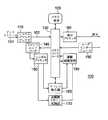
従来の受信部100が図1に示してある。受信及び復号は2つの基本的な段階で行われる。第1の段階においては、圧縮されたビデオデータから特徴が抽出され、第2の段階では、抽出された特徴を用いてビデオの再構築もしくは再編成が行われる。
【0007】
第1の復号段階では、デマルチプレクサ(demux)110が圧縮されたビットストリーム101を受ける。該デマルチプレクサは、受信したビットストリームのパケットに同期し、ビットストリームのビデオ部分、オーディオ部分及びデータ部分を一次ビットストリーム102に分離する。この時点では依然として圧縮されている1次ビットストリームはメモリコントローラ130を用いて共有メモリ装置120に送られる。フロントエンド パーサ140は、圧縮されたビットストリームをパース(解析)する。このパーサ140は、ビットストリームの高レベルのシンタックス(構文)、例えば、MPEG−2規格でスライスレイヤより上のシンタックスを抽出する機能を有する。
【0008】
上記レベルより低いレイヤーもしくはレベルのビットはシンボル プロセッサ150に転送される。このシンボル プロセッサ150は主に、可変長復号(VLD)動作を行う。MPEGビットストリームでは、例えば、運動ベクトル及び離散コサイン変換(DCT)係数が可変長コードによって、マクロブロックコード等のような他の情報と共に符号化されている。
【0009】
第2の復号段階において、付加的なブロックを取り込んでビデオ信号を再編成する。シンボルプロセッサから、抽出されたマクロブロック及び運動ベクトル情報がアドレス発生部160に送られ、DCT情報は、逆離散コサイン変換部、即ちIDCT部170に送られる。
【0010】
アドレス発生器160は、メモリ装置120にビデオデータを書き込んだり該メモリ装置120からデータを読み取ったりするためのメモリアドレスを発生する機能を有する。該アドレス発生器は、予測モード、現在ブロック位置及び運動ベクトル値のような情報に大きく依存する。これら情報の幾つかは、運動補償装置180に転送され、該運動補償装置180はメモリ装置から読み出されたデータとIDCT部170から受け取ったデータとを結合する機能を有する。
【0011】
モード内予測(intra mode prediction)の場合には、メモリから読み取られるデータは予測情報であるので、メモリから読み出すデータが無い場合が有り得る。再編成されたデータは、運動補償装置180からメモリ120に書き込まれる。このデータを表示すべき時点になると、表示プロセッサ190が当該データを読み込んで必要となり得る付加的な処理を行う。ユーザインタフェース195はメモリコントローラ130との相互作用で、限定された位置アクセスを実現する。
【0012】
ネットワーク化
今や、コンピュータ技術は、家庭や企業を通し多くのインテリジェントな電子デバイスをネットワーク化することができる程充分に低コストで実現できる。現在ではまた、ワールド ワイド ウェブ(World Wide Web:WWW)を利用してデバイス間でディジタルデータをオーディオ、画像及びビデオの形態で転送したり、相互にデータ情報を共有することも可能である。
【0013】
ユニバーサル プラグ アンド プレイ(Universal Plug and Play:UPNP)が、ネットワーク化されるデバイスに対し使用が容易で汎用性があり規格に基づく接続を実現する上でイニシアティブを取っている。UPNPは、パーソナルコンピュータ、即ちPC、ディジタル装置及び無線装置をネットワーク化するための構成要素である。UPNPは、家庭、企業並びにウエブ(Web)接続が可能なあらゆる箇所でネットワーク化されたデバイス間でのデータの制御及び転送を行うためにTCP/IP及び上記 Web 或るいはその他の単純な制御プロトコル(Simple Control Protocol:SCP)を用いる。
【0014】
UPNPは、特別なコンフィギュレーション要することなくネットワーク内で動作するように企図されている。即ち、UPNPは、ネットワークを動的に結合したり、インターネットプロトコル(Internet Protocol:IP)アドレスを得たり、要求に応じ当該UPNP自体及びその能力を公示したり、ネットワーク内の他のデバイスの存在及び能力に関し学習したりすることができるデバイスである。また、このUPNPは、ネットワークの結合に加え、不所望な状態を何ら残すことなくネットワークから離脱することができるデバイスである。
【0015】
セキュリティ システム(安全保護システム)
従来の殆どの監視システムにおいては、屋内及び屋外の場面もしくはシーンについてのビデオを得るのに閉回路テレビジョン(CCTV)方式を採用している。この種のセキュリティ システムにおいては、典型的に、保安作業員が同時に観察可能なようにビデオをモニタ上に表示したり、後で再生して観察するために微速度モードでビデオを記録したりする。
【0016】
このような方法には由々しい制限が存在する。第1に、人間がビデオ監視のような作業において処理することができる可視情報の量には限界がある。時間が経てば、有意味なセキュリティ イベントが容易に見過ごされ得る。また、多数のビデオを観察しなければならない場合には、監視の有効性が低減する。事後的に分析するために記録されたビデオでは実時間ベースでの関与が不可能である。加えて、ビデオ記録の容量には限界があり、更に故障の可能性がある。
【0017】
一般に、ビデオは、組織化もしくは体系化されておらず、またインデックスも付けられていない。有意味なセキュリティイベントを探知するための効果的な手段無しでは、保安作業員が総ての稼動中のカメラからの出力を監視したり或るいは記録することはコスト的に見合わない。セキュリティイベントを大雑把に検出するためにビデオ運動検出を利用することができる。例えば、保安領域内でのあらゆる運動を有意味なイベントと見做すことができる。しかしながら、複雑な場面、即ちシーンにおいては、非常に単純な運動検出スキームでは不充分である。
【0018】
米国特許第5,594,842号明細書には、群運動ベクトルを用いてイベントを検出する監視システムが記述されている。また、米国特許第6,031,582号明細書には、運動ベクトルに対応する信号強度差を用いてイベントを検出する監視システムが記述されている。
【0019】
米国特許第6,064,303号明細書には、疑わしい或るいは特色を表していないイベントを検出するために周囲環境を監視するパーソナルコンピュータ(PC)ベースの家庭用セキュリティシステム(保安システム)が記述されている。或る閾イベントが検出されると、このシステムは付加的なイベントに対し緻密な監視を行う。このようにして、累積された検出イベントが或る閾値を越えると、セキュリティシステムは適当な対処活動を行う。このシステムは、パターン認識により音響及びビデオイベントを検出する。音響イベントは、予め記録されているファイルを用い、高速フーリエ変換で処理され、時間の関数として種々な離散的な特性周波数を有する振幅に変換され、他方、検出されたビデオイベントは、運動(大きさ及び持続期間)、光のコントラストの変化及び明暗の変化で表される。個々のイベントは、関連の重大度を有する。応答は、予め記録されているメッセージを用い関連の番号の電話設備を用いて行われる。
【0020】
米国特許第5,666,157号明細書には、或る領域の実像を、第1の解像レベルの電子的ビデオ信号に変換するためのビデオカメラを有する異常検出/監視システムが記述されている。このシステムは、上記領域内に存在する個々人の運動を標本化するための手段を備えている。標本化された運動のビデオ信号は、犯罪意図を有する人物を表す既知の運動特性と電子的に比較される。その上で、犯罪意図のレベルを決定し、適当な警報信号を発生する。
【0021】
MPEG−7文書ISO/IEC JTC1/SC29/WG11/N2861、「MPEG−7 Applications Document v.9」(1999年7月発行)には、カメラが要注意領域を監視し何らかのイベントが生じた場合に活動をトリガする監視システムが開示されている。このシステムでは、情報を有していない或るいは限られた情報しか有していないデータベースを構築し、時間の経過と共にビデオデータベース及びメタデータを形成する。(「エンコーダ」側での)メタコンテンツの抽出及び(「デコーダ」側での)メタデータの利用においては同じデータベースを用いるものとしている。
【0022】
しかしながら、多くの安全保護用途においては、実時間ベースでのイベントの解析が要求される。上記のMPEG−7 Applications Document では、どのようにして実時間パフォーマンスを達成するかに関する情報は与えられていない。更にまた、高速で信頼性があり且つ正確なイベント検出を達成するために抽出しなければならない実際のメタデータについては規定がない。最後に、この文書には、抽出装置及び他のネットワーク化したデバイスの動作に関し何ら言うべきものがない。
【0023】
従って、上述のようにビデオ符号化及びネットワーク化技術を利用する改良された監視システムを実現することが望ましい。
【0024】
【発明の概要】
本発明は、圧縮されたディジタルビデオ信号から抽出された運動ベクトル及びDCT係数に基づいて、低レベルの特徴を抽出する特徴抽出装置と、上記特徴抽出装置に接続されて上記低レベルの特徴をコンテンツ記述子として符号化する記述エンコーダを含む監視/管制システムを提供するものである。上記システムはまた、上記記述エンコーダに接続されて、上記コンテンツ記述子からセキュリティイベントを検出するためのイベント検出器と、上記イベント検出器に接続されて、セキュリティイベントの検出に応答し制御信号を発生するための制御信号プロセッサとを含む。
【0025】
本システムは、更に、互いにネットワークにより接続された電話器、パーソナルコンピュータ及びビデオレコーダを含む。該ネットワークは、上記制御信号を搬送するための低周波帯域幅のネットワークと、上記圧縮されたディジタルビデオ信号及び上記コンテンツ記述子を搬送するための高周波帯域幅のネットワークとを含む。メモリ装置は、上記圧縮されたディジタルビデオ信号、上記コンテンツ記述子、上記制御信号、ユーザ入力及びユーザのコンフィギュレーション オプションを記憶する。
【0026】
本監視/管制システムは、更に、上記特徴抽出装置に接続されて上記圧縮ディジタルビデオ信号から運動ベクトル並びにマクロブロック及びDCT係数を抽出するシンボルプロセッサを具備すると共に上記メモリ装置に接続されて、上記圧縮されたディジタルビデオ信号及び上記コンテンツ記述子を含む圧縮された出力ディジタルビデオ信号を発生するためのビットストリームプロセッサを具備する。
【0027】
【発明の実施の形態】
ネットワーク化した監視/管制システム
図2は、本発明による監視/管制システム300を備えたネットワーク200を示す。このシステムは、1個または複数個のディジタルビデオカメラ201乃至202、モニタ(テレビジョン:TV)203及びリモートコントローラ203’、ビデオレコーダ(VCR)204、電話器205、無線電話器206、記憶装置(HDD)207、パーソナルコンピュータ208、汎用ディスク装置(DVD−RW)209及び遠隔場所のパーソナルコンピュータ(PC)210から構成されている。上記装置201乃至210及び監視/管制システム300は、ネットワークを介して相互に通信することができる。ここで、ネットワークは、例えば、ローカルインタネット211及び広域インタネット212並びに無線区間213を含むことができる。
【0028】
ネットワークの動作
動作中、ネットワークは、低周波帯域幅の制御信号及び高周波帯域幅のデータメッセージ或るいはビデオコンテンツを搬送する。
【0029】
制御信号
制御信号は、UPNP、電力線、家庭用プラグ、電話回線或るいは他の何らかのプロトコルを用いて装置間で転送することができる。これら制御信号は、両立性のある異なった装置をして他の装置の制御を可能にすると共に、これら制御信号は、装置間で共有したり通信したりすることができる。例えば、制御信号を用いてカメラ201乃至202をオン/オフ制御したり、カメラを(上下或るいは左右に)動かしてズームイン或るいはズームアウトすることができる。メッセージは自動的に発生したり或るいはユーザによって発生することができる。例えば、カメラを周期的にオン/オフすることができるし、或るいはユーザがリモートコントローラ203’、PC(ローカルコンピュータ208或るいは遠隔コンピュータ209)、VCR204、DVD209或るいはTVを用いてカメラを制御することができる。同様にして、パーソナルコンピュータ(PC)或るいは電話器を用いて制御信号を他の装置や消費者の電子デバイス、例えばVCRやDVDに送ることができる。
【0030】
ビデオ信号
ビデオ信号は、ネットワーク211を介しIEEE−394規格に従い伝送することができる。カメラがオン状態にある時には、ビデオをモニタ上にフルウインドウ或るいは映像内映像(PIP)ウインドウとして表示することができる。該ビデオはまた、VCR、DVD或るいはHDD(ハードディスクドライブ)で記録することも可能である。ビデオ情報は、将来の操作及び観察の目的で、例えば、MPEG−7コンテンツベースの記述子のような高レベルのメタデータを含むように符号化される。この符号化は、カメラ内で行うこともできるし、或るいはパーソナルコンピュータもしくはPCまたは監視/管制システム300で行うことも可能である。PCはまたコード変換を行うことができる。即ち、該PCは、ビデオ情報をMPEG−2またはMPEG−4から、可能ならば低いビットレート、低い空間解像度或るいはNTSCフォーマットで他のより望ましい符号化された情報に変換することができる。符号化されたビデオ情報は、VCR、DVD或るいはHDDに記録することができる。符号化に就いては追って詳細に説明する。
【0031】
ユーザは、記録後、記録されているセキュリティイベントに高速且つ効率的にアクセスするために、ビデオブラウザ(閲覧ソフトウエア)を用いてビデオを点検することができる。例えば、ユーザが一週間留守にして家のビデオを記録して置いた場合には、ユーザは家に近付く人物を含む場面のみを観察するだけで良く、その他の有意味なセキュリティイベントを含まない何百時間分ものビデオを観察する必要はない。
【0032】
セキュリティイベントの検出に応答して、本システムは、電話器に対する制御信号を用い、警察、消防署或るいは緊急機関のような適切な非常対処機関にダイヤルすることができる。本システムはまた、イベントの性質に依存し他の任意適当な電話番号を選択することも可能である。更にまた、第3世代(3G)のセル方式電話器(携帯電話)が利用可能である場合には、カメラの出力をそのまま、3G電話器と通信可能な電話設備に送ることができる。
【0033】
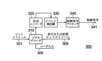
監視/管制システムの概要
図3は、監視/管制システム(以降、SCSとも称する)300の主たる構成要素を示す。本監視/管制システムもしくはSCSは、記述エンコーダ320及びイベント検出器330に接続されたビデオ受信/復号/表示器(「デコーダ」)を備えている。また、追って詳細に説明するように、記述エンコーダ320及びイベント検出器330は相互に接続されている。制御信号プロセッサ340がイベント検出器の出力端に接続されている。復号器、即ちデコーダはユーザ入力305を受け付けてSCSのコンフィギュレーションを設定する。ここで、受け付けることができる入力の種類並びにSCSの動作に対する該入力の影響について詳細に説明する。図1に示したシステムの場合と同様に、圧縮されたディジタル入力ビットストリーム301は、ビデオデコーダ310により受け取られる。SCSの出力309は、表示可能なビデオデータストリーム、制御信号及び増補もしくは拡張ビットストリームを含むことができる。制御信号発生器は、検出されたセキュリティイベントに応答して制御信号341を発生する。この場合の1つの利点は、増補もしくは拡張ビットストリームがセキュリティイベントを検出するのに有用な情報を含んでいることである。
【0034】
ネットワーク化した装置201乃至210が改良されたセキュリティ動作を行うのを可能にするために、本発明のシステムは、記述エンコーダ320を用いて特徴の抽出を行う。記述エンコーダは、出力ビットストリームを拡張(増補)するためにコンテンツの記述を発生する。増補もしくは拡張ビットストリームは元の入力ビットストリーム301を含むことができる。
【0035】
イベント検出器330は、抽出された特徴を用いて、高レベルのコンテンツを発生し、デコーダ310にセキュリティイベントを表す信号を供給する。制御信号プロセッサ340は、セキュリティイベントに応答して制御信号を発生し、この制御信号は、ネットワーク装置201乃至210に伝送される。
【0036】
図4は、監視/管制システム、即ちSCS300をより詳細に示す図である。本発明のSCSは、図1の再生システムとは、内部動作及び出力に関して異なる。図4に示してある点線は、従来のビデオ再生システムには存在しない構成要素に対する接続を示している。
【0037】
SCS300は、多重分離器もしくはデマルチプレクサ(demux)410と、メモリ装置500及びメモリコントローラ430と、フロントエンドパーサ440と、シンボル(記号)プロセッサ450とを含んでいる。これらシステム構成要素は、第1段階の復号中、特徴の抽出455に用いられる。
【0038】
また、本システムは、アドレス発生器460、逆離散コサイン変換部、即ち逆DCT(IDCT)470、運動補償装置480及び表示プロセッサ490を備えている。これら構成要素は、第2段階の復号中にイメージもしくは像の再編成(再生)及び表示402を発生するのに用いられる。尚、後述する或る種の動作モードにおいては、従来の受信部とは対照的に、第2段階の復号中に用いられる叙上の構成要素をオフにして全メモリ帯域幅及び処理優先度を特徴の抽出及び第1段階の復号に割当てることができる。
【0039】
内部動作への切り換えは、特徴抽出装置410及びMPEG−7記述エンコーダ320の動作の結果として行われる。特徴抽出装置455は本明細書で説明する動的特徴抽出を実行する。運動ベクトル情報、DCT係数及び形状情報を含む低レベルのデータはシンボル(記号)プロセッサ450から特徴抽出装置455に転送される。
【0040】
後述するように、この低レベルデータは、サーチ及び検索に有用であるMPEG−7記述子に写像することができる。この写像(マッピング)は、記述エンコーダ320によって行われる。また、該エンコーダは、フロント エンド パーサ440及びシステム デマルチプレクサ410から情報を受けることができる。
【0041】
好適な実施の形態においては、エンコーダは、選択された規格、例えば、MPEG−7規格に従って記述スキームを実体化(instantiate)する。尚、他の規格に応じて他の形式のエンコーダもを使用可能であることは理解されたい。規格に従っての符号化で、装置201乃至210間の相互動作が可能になる。記述スキームはイベント検出器330に転送される。抽出されたデータも、メモリコントローラ430を介してメインメモリ装置500に転送することができる。
【0042】
イベント検出器330は、セキュリティイベントを検出し、検出されたイベントをシステムの他の構成要素、特に、制御信号プロセッサ340に信号で報知する。ユーザ入力305は、個人情報及びオプション入力305に対しシステムのコンフィギュレーションを設定するのに用いられる。ここで個人情報には、例えば、職場、携帯電話、ページャ、e−メイルアドレス、警察署、消防署、救急機関のような接触先電話番号、接触の優先度、即ち、e−メイルを先に送り、特定の時間内に応答がない場合には警察署に電話するとか或るいは総ての接触先に報知する等の接触優先順位、日/時のカストマイズ、例えば、VCR、DVD、TV、PC、モニタ等のビデオ出力を送るための作業場所を呼出して6pm以前にはe−メイルを送り、6pm以後には携帯電話を呼出す等の日/時カストマイズ情報を含む。
【0043】
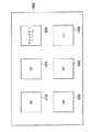
図5に示すように、本発明のセキュリティシステムのメモリ500は、4種類のビデオデータ、即ち、元の圧縮されたビットストリーム(BS)510の総てもしくは一部分、関心のあるビデオを再編成したり、その概要を作成するために選択されたフレーム(セキュリティフレーム)520、記述スキーム(DS)530及びユーザ入力(UI)540を記憶する。このメモリはまたイベント検出器により出力される制御信号(CS)501並びに上述したようコンフィギュレーションに関するユーザオプション(UP)502を記憶する。
【0044】
本発明のシステムはまた、特徴抽出能力を有することに加えて、ビットストリームプロセッサ491を介し拡張ビットストリーム401を出力することができる。該ビットストリームプロセッサは、このデータを、メモリコントローラを介してメイン メモリ装置から受け取る。出力ビットストリームは、圧縮されたコンテンツ、即ち、元のビットストリーム301、コンテンツのサマリ(要約)及びコンテンツの記述を含むことができる。ビットストリームプロセッサは、この情報をコンテンツが存在する場所から遠隔のユーザに対し伝送したりネットワークを介して記録装置に電送するのに適した仕方でフォーマット化する。
【0045】
コンテンツ及び(または)その対応の記述を出力する目的は、ユーザに対して、信号で伝送されたセキュリティイベントを遡及的に追跡するのを容易にする情報を提供するためである。上記の記述は、コンテンツ内のキーポイントの高速検索に使用することができる。
【0046】
ネットワークを介して伝送される実際の制御信号341は、制御信号プロセッサ340によって発生される。該制御信号プロセッサは、イベント検出器からセキュリティイベントが検出された旨の報告を受け、ユーザのオプション情報を参照し、対応のネットワーク装置に適切な制御信号を発生する機能を有する。
【0047】
制御信号の種類は、3つの範疇、即ち、(i)ユーザ入力として与えられる保安接触情報、(ii)カメラの運動、切換及び操作並びに記録、電話発呼のような活動データ等の装置制御パラメータ及び(iii)例えば、HDD207に対する拡張ビットストリーム401の伝送及び電話器205或るいはPC210への適切な電話番号の送出等のルーチング(経過指定)情報に分類することができる。
【0048】
システム動作
本発明の監視/管制システム、即ちSCS300は、圧縮されたディジタル ビデオ信号から動的に特徴、即ち特徴を抽出する。これら特徴を用いてセキュリティイベントを検出し、対処活動もしくはアクションを自動的に開始することができる。
【0049】
本システムの1つの大きな特徴は、他の装置との動作両立性にある。この動作両立性は、ビデオのコンテンツを配送し再生するのに標準の圧縮技術を用い且つコンテンツを記述し、検索しアクセスするのに標準の記述スキーム(DS)を用いることにより実現することができる。本発明のSCSはイベントのステータスに依存し、数多の異なったモードで動作可能である。
【0050】
部分復号−出力を伴わないイベントのサーチ
第1のモードにおいては、受信した圧縮ビットストリームは本発明の監視/管制システム、即ちSCSによりパース(解析)されて部分的に復号される。この「部分復号」とは、第1段階の復号動作を含むだけの復号と定義される。このモードにおいては、ビデオを再編成するための第2段階の復号は不能である。換言するならば、この部分復号モードにおいては、従来の受信システムとは異なり、アドレスの発生も行わなければ逆DCTの計算も行われず、また運動補償も行わなければ、勿論のこと表示も行われない。即ち、第2段の復号化は側路されるのである。このモードにおけるSCSの主たる目的は、圧縮されたビデオ信号から抽出された特徴によりセキュリティイベントをサーチすることである。
【0051】
表示が行われないので、全メモリ帯域幅を、部分復号並びに特徴の抽出、符号化及びイベントの検出専用に割り当てることができる。その結果、このモードにおいて、本システムは、圧縮された入力ビットストリームの選択された要素(エレメンツ)を効率良く処理してコンテンツについての低レベル及び高レベルの情報を抽出することが可能である。部分復号で、比較的短時間内に有意味な特徴を抽出できる。例えば、数時間分のビデオを、数分或いはそれより短い時間内で処理することが可能である。
【0052】
この目的に有用である抽出されたビットストリーム要素の例としては、ビットストリーム内の運動ベクトル、DCT係数及び映像/マクロブロック符号が挙げられる。これら要素はシンボル プロセッサ450及びフロントエンドパーサ440から出力される。更に、副ビットストリームから情報を抽出することも可能である。この種の情報はシステムのデマルチプレクサ(demux)410から出力される。この種のデータの一例として、MPEG−7メタデータがあり、日時スタンプ情報のようなコンテンツに関する注釈情報を含むことができる。
【0053】
ビットストリームを部分的に復号して情報を抽出することにより得られる利点は、比較的短い時間内に特徴を収集しセキュリティイベントを検出することができる点にある。この部分復号モードは、特記すべきイベントが未だ検出されていない場合の受動的監視に対して最も良好に適用可能である。
【0054】
全復号−イベントの検出または連続表示出力
第1段階の部分復号モードとは対照的に、第2のモードは、分析中のビデオを再編成してローカル表示装置に出力する点で第1のモードと異なる。この全復号モードにおいては、部分復号モードについて述べたのと同じ仕方で特徴を抽出しコンテンツ記述子として符号化する。しかしながら、この特徴抽出はビデオデータの表示と同時に行われる。言い換えるならば、ビデオを再生しながらであるので、特徴の抽出及び符号化は動的、即ちダイナミックであると言える。
【0055】
この動作モードは、単一または複数のカメラを備え単一または複数のビットストリームがSCSに入力され常に信号が表示されるシステムに対して適用可能である。表示装置は単一であっても或いは複数であっても良い。多数のカメラを用い然も表示装置が少数である場合には、本SCSは、ビットストリームを再編成し、再編成したビットストリームを表示するように制御を行うことができる。主要な点は、ビデオを再編成し且つ表示しながら圧縮されたビデオ信号を分析することである。
カメラ及び表示装置がそれぞれ1台しか設けられていない特殊事例においては、本SCSは、セキュリティイベントの検出で全符号化モードに入ることができる。
【0056】
混成複合
第3のモードにおいては、圧縮されたビットストリームを可能最高のビットレートで受信し処理しつつ、ビットストリームの部分復号が行われる。部分的に復号されたビットストリームは、メモリ装置500に格納される。同時に、ビデオを表示することができるように、メモリ装置に格納されている復号されたビットストリームから第2段階の再編成が行われる。特徴を抽出し符号化イベントを検出するのに要する期間中、フレーム レートを例えば毎秒15フレーム或るいはそれ以下に減少して、より多くのシステムリソース(資源)が特徴抽出、符号化及びイベント検出に利用可能になるようにすることができる。
【0057】
このモードの典型的な応用例においては、ビデオから特徴を連続的に抽出する。セキュリティイベントが検出されると、該イベントの分析のためにより多くのシステムリソースが必要となり得る。この場合には、復号用リソースには低い優先度が与えられ、それにより、充分ではあるが低い時間的解像度のビデオ信号を表示したり記録したり或いは伝送するのに充分なリソースを与えることができる。
【0058】
これらモードの何れにおいても重要な点は、選択された規格に従うメタデータが利用可能な圧縮データから抽出されることである。ここで、利用可能なデータは、圧縮されたビットストリームから抽出される低レベルの特徴或るいは副データストリームからの情報だけあっても良く、完全な或るいは完全ではない何らかのMPEG−7メタデータを含んでいる。このようにして他の装置との動作両立性が達成される。
【0059】
特徴の抽出
圧縮されたビットストリームからの特徴の抽出は、多くの文献に報告されている。この種の抽出の主たる利点は、デマルチプレクサ、パーサ及びシンボルプロセッサの出力に依拠することにより逆DCTの計算を回避できるという理由から計算が単純であるという点に見られる。シンボルプロセッサの出力には、運動ベクトル情報及びDCT係数が含まれる。
【0060】
このような抽出に最も応じ易い特徴は、色、輝度(ルミナンス)及び運動である。また、特徴抽出装置455の出力は、記述子の値を実体化する記述エンコーダ320にも送られる点に留意されたい。実体化された記述子(description instantiations)は、次いで、イベント検出器330で用いられる。
【0061】
ルミナンス及びカラー:I−フレームでは、シンボルプロセッサ450の出力には、ブロックのルミナンス及びクロミナンスの「dc(直流)」値が含まれていることに注目されたい。従って、I−フレームの「dc画像」は、シンボルプロセッサ450の出力を用いて容易に構成することができる。dc画像を用いて場面の変化を如何に検出するかに関しては周知である。また、dc画像から、主たるカラー(主色)、カラーヒストグラム、コンパクトカラー、GOF/GOPカラーヒストグラム、カラー組成ヒストグラム、カラーのレイアウト等々のようなカラー記述子を決定することも可能である。例えば、下に掲げた表1における主色記述子のバイナリ構文を参照されたい。
【0062】
【表1】
MPEG圧縮ビデオ信号では、YUVまたはYcrCb、カラー量子化、即ち、ビンの数、色閾値の初期値等々に対する色空間デフォルト値は、主カラー数もしくは主色数の場合と同様に特徴抽出装置自体によって決定され点に留意されるべきである。その場合、信頼度、色値及び百分率は、マクロブロックの色のdc値を用いて、当該マクロブロックに属するそれぞれのピクセルの色と同様に画像自体から決定される。このことから、主色をシンボルプロセッサ450の出力からどのようにして決定できるかがおおよそ理解されるであろう。
【0064】
P−フレームからdc画像を得るためには、シンボルプロセッサの出力を異なった仕方で処理しなければならない。この処理は、マクロブロックが通常予測的に符号化されているために異なってくる。dc成分を得るために、DCT領域で運動の補償を行う方法、例えば、米国特許願第08/742,124号明細書「Digital video decoder and method of decoding a video signal」に記載されている方法のような方法を用いることができる。この場合の計算オーバヘッドは、逆DCTの計算に要するオーバヘッドよりも相当に低い。
【0065】
運動: 圧縮された領域で運動の特徴は、比較的容易に抽出することができる。その理由は、運動について補償が行われたフレームの場合、シンボルプロセッサの出力には、各マクロブロック毎に運動ベクトルが含まれているからである。運動ベクトルからの特徴抽出には幾つかの試みが提案されている。例えば、米国特許願第09/236,838号明細書「Method of feature extraction of video sequences」を参照されたい。
【0066】
圧縮領域において決定することができるMPEG−7運動記述子には、運動アクティビティ(活動度)、カメラの運動、運動軌跡及びパラメトリック運動が含まれる。下に掲げる表2に示すような運動活動度記述子のバイナリ表示構文を参照されたい。
【0067】
【表2】
上に示した総ての欄のパラメータは、シンボルプロセッサから出力される運動ベクトルから容易に算出することができる。例えば、強度パラメータは、運動ベクトルの大きさの標準偏差を最初に計算し次いで該標準偏差を3ビット値に量子化することにより算出される。
【0069】
メタデータ符号化器
MPEG−2またはMPEG−4には、取り扱い易いビットストリームを発生するのに使用しなければならない良好に規格化されたエンコーダ構造がある。適合点は、プロフィル/レベル定義に基づいている。即ち、MPEG−2Main Profile@High Level(MP@HL)エンコーダは、映像のサイズ、データ レート等々の点で制限されている。しかしながら、運動の評価を行わなければならない幾つかのブロック、DCTを行う必要のあるブロック等々が存在することが知られている。ベース及びエンハンスメント レイヤを符号化しなければならないスケーラビリティ プロフィルの1つで動作している場合には、エンコーダの構造をどのように変更する必要があるかは知られている。これは、規格により明瞭に定義されている。
【0070】
MPEG−7において、実体化記述スキームはMPEG−7エンコーダと同様である。しかしながら、多くの異なった型式のメタデータには広汎な記述スキームが所属する。各種のデータを如何に作成するかは特殊であり、規格によって特定されていない。MPEG−7にとっては、記述スキームをどのように実体化するかに関して特定するのは恐らく無理であり、然もこれは規格の規範的な部分であるので、MPEG−7エンコーダについての構造規格は存在しないと言える。従って、各DSはケースバイケースで実体化しなければならず、特定のアプリケーションの範囲内で有意味になることができる。
【0071】
ここで重要な点は、汎用のMPEG−7エンコーダは、特定の目的或るいは用途が念頭に無い場合には有意味でないことである。ここで、目的とするところは、改良されたコンテンツベースでのアクセスを達成することであり、従って、本発明のSCSが実体化する記述スキーム並びに本システムに独特な実体化方法(instantiation method)について以下に説明する。
【0072】
ここで、明らかにしておきたいもう1つの点は、本発明のセキュリティシステムは他の装置との動作両立性を達成するためにメタデータを符号化することである。この他の装置との動作両立性が必要なければ、MPEG−7規格に従ってメタデータを符号化する必要はない。即ち、システムは単に、それ自身が所有する内部的で且つ該特定のシステムだけが理解する記述子及び記述スキームを使用するだけで良い。この場合には、増補もしくは拡張ビットストリームをも出力する必要はない。
【0073】
記述スキームインスタンシエータ(記述スキーム実体化モジュール)の詳細
記述スキーム(DS)は、記述子の容器と考えることができる。また、記述スキームは、各種の記述子を組織化するデータ構造であると見ることもできる。これと関連して、MPEG−7マルチメディア記述スキーム ワーキング ドラフト(Multimedia Description Scheme Working draft)から抜粋した付録Aに記述されているMPEG−7ビデオセグメント記述スキーム(DS)の用語上の意味について参照されたい。
【0074】
記述子に関する箇所で述べている色(カラー)及び運動記述子がビデオセグメントDS(VideoSegment DS)でどのように取り上げられているかについて述べておき度い。この場合、記述スキームは、先に述べたように構成記述子の各々を決定することにより実体化(instantiate)することができる。ビデオセグメントDS(VideoSegment DS)は、圧縮領域もしくは定義域での特徴の抽出により実体化することが可能であることに留意されたい。このように、ビデオセグメントDSは、個々の記述子をそれ自体で使用することを可能にすると共に、ここで述べている監視アプリケーションを可能にする他の記述子と組合せて使用することを許容する。
【0075】
ビデオセグメントDSは、コンテンツの構造上の特性を記述するMPEG−7規格のDSの一例である。他のこの種のDSには、セグメントDS及びその子供、例えば運動領域DS(Moving Region DS)等々が含まれる。他のDSには、要約DS(Summary DS)により可能化される要約(summarization)のようなアプリケーションを強調するDSがある。
【0076】
ウエイトDS(Weight DS)は、記述スキームにおける各種記述子の相対重み付けを表す。従って、相対重み付けは、要求に応じMPEG−7DSインスタンシエータで実体化することができる。エンティティ関連グラフDS(Entity-Relation Graph DS)は、異なったエンティティ間における関係を表現する。シンボルプロセッサの出力は、「よりアクティブである」、「最もアクティブである」、「より高速である」、「より大きい」、「より新しい」等々のような関係の同定もしくは識別を可能にする。従って、このクラスの対応のエンティティ関係グラフは圧縮された定義域において実体化することができる。
【0077】
時間DS(Time DS)、メディア ロケータDS(Media Locator DS)、グリッド(Grids)及びヒストグラム(Histograms)のような基本的なDSがある。これらDSは総てのDSに適用可能であり、従って基本的に重要である。エンコーダ320に組み込まれているシンボル プロセッサ450の出力を処理することで、これら記述子スキームの総てを複製することができる。例えば、圧縮されたビットストリーム内に存在するタイム スタンプ情報を用いて、監視アプリケーションに対し非常に重要な特徴である時間DS(Time DS)を副次的に生成する、即ち複製することができる。
【0078】
MPEG−7はまた、テキスト記述(注釈DS)、概念上のアスペクト(例えば、意味論的記述スキーム)、コンテンツの本来的性質(例えば、モデルDS)を表現する「高レベル」のDSをも含む。
【0079】
要するに、システム デマルチプレクサ110、フロントエンドパーサ440及びシンボル プロセッサ450が提供する情報を用いて強力な記述スキームの部分集合をインスタンシエート(instantiate)、即ち実体化することが可能である。
【0080】
セキュリティイベントの検出
自動的なセキュリティイベントの検出には、低レベル情報からの高レベル情報の推測が行われる。と言うのは、直接且つ自動的に得ることができるのは低レベルの情報だけだからである。単純な例として、保安領域に侵入する侵入者の検出について考察してみる。保安領域を監視している観察者は、当該領域のセマンチックな、即ち高レベルの特徴における変化に注目することにより侵入者を直ちに検出し得ることは言うまでもない。他方、本発明の自動セキュリティイベント検出システムは、排他的にカメラによって捕捉されるオーディオ−ビデオ情報の自動処理に依拠する。カメラからのオーディオ−ビデオ情報(信号)は、色、運動、音量等々のような低レベルの特徴しか含んでおらず、標識の付いた保安領域や侵入者のような意味論的情報は含んでいない。しかしながら、一般に、侵入者の侵入のような意味論的イベントは、カメラにより捕捉されるオーディオ−ビデオシーンの低レベルの特徴に対し直接的なインパクトを与える。
【0081】
上述の単純な例においては、保安領域の運動アクテビティ(活動度)は、侵入者が存在しない場合は零である。と言うのは、このシーンもしくは場面には運動する客体、即ちオブジェクトが存在しないからである。侵入者が侵入すると直ちに、運動アクテビティが急激に増加する。侵入者が去ると、運動アクテビティは再び通常の低レベルに戻り、この低レベルに留どまる。この場合には、オーディオ−ビデオシーンの運動特徴だけで、侵入の開始及び終わりを検出するのに充分である。同様に、侵入者の顔が捕らえられると、場面のテクスチャに変化が生じ、場面に顔の存在が表示される。また、この場合には、侵入により音量を大きくすることができよう。
【0082】
キーポイント、即ち重要な点は、捕捉されたオーディオ−ビデオ情報の低レベルの特徴における変化で屡々、場面の意味論的内容に変化が生ずることである。なお、保安領域内への侵入者の侵入は、イベントの単なる一例であることは言うまでもない。本発明のシステムは、このような単純なイベントに制限されるものではなく、低レベルの特徴を用いて検出することできるあらゆるイベントに適用可能である。
【0083】
本発明のシステムはまた、予め記録されているオーディオ−ビデオ情報からイベントを検出することも可能である。このような「事後的」監視も保安システムにおいては有価値である。
【0084】
イベント検出器330における低レベル特徴の他の特定の利用例として、イベントが終了したこと(例えば、侵入者がカメラの視野から去ったこと)を観察し、このようなイベントを生起せしめた客体もしくはオブジェクトのパラメトリックな運動を抽出することである。ここでパラメトリックな運動とは、MPEG−7によって採用されているビデオ記述子である。このパラメトリック運動を用いて、カメラ201乃至202の位置を自動的にイベントを追跡するよう調節することができる。イベントを検出したのと同じカメラで、当該イベントを追跡し続けることが不可能である場合には、パラメトリック運動を用いて他の要所要所に配置されたカメラを選択することもできる。
【0085】
最も広い意味において、本発明の監視システムの目的は、正常な状態から異常な状態を識別することにある。侵入者の例をとれば、状態の変化が音響及び運動の活動度、即ちアクテビティにより識別され、この場合正常な状態のオーディオ−ビデオ特徴は実質的に零である。しかしながら、殆どの実際上の保安用途において、正常の状態は零ではない。これを、便宜上、非零正常状態(NZ−NS)監視と称する。
【0086】
非零正常状態監視もしくはNZ−NS監視を説明するための第1の例として、静止していたり運動している人々、自転車に乗っている者、自動車、バス及びトラック並びに非常に複雑なオーディオもしくは音響信号が存在する交通領域を観察するために取り付けられているカメラを考える。MPEG−7記述子を用いデータの学習で、事故、暴行、交通違反等々のようなセキュリティイベントを抽出することが可能である。NZ−NS監視はまた、混雑している商店等で万引きの検出や誤魔化しの検出に使用することもできる。本システムはまた、自動化された製造設備でコンベアベルト上の不合格部品を検出したり何らかの機械から出る煙りや奇妙な雑音を検出するのにも有用である。
【0087】
制御信号プロセッサ
制御信号プロセッサ、即ちCSP340は、イベント検出器330からの割込みを受けて、図2のネットワークに接続されている他の装置に対し適当な制御信号を発生する。このような制御信号で、セキュリティイベントを検出している場合にはテレビジョン上に現れるPIPウインドウを発生したり、電話番号をダイヤルしたりまた予め記録されているメッセージを再生したり、或るいはe−メイルを送ったり、或るいはパーソナルコンピュータ上にウインドウを立ち上がらせてカメラの1つからの映像を表示したりすることができる。また、このような制御信号はユーザの選択したオプションに従いカストマイズすることが可能である。更にまた、応答活動の順序に優先度を割り当てることもできる。
【0088】
応用シナリオ例
ローカルな監視用途においては、SCS300はモニタ/TV及び記録装置にビデオ内容を供給する。これによりイベントが検出され、警報が起動され、電話設備を介して関連の人に接触が取られる。ユーザはまた、リモートコントローラのような他の両立性のある装置を介してカメラを制御することもできる。遠隔監視用途例においては、SCS300は上述のローカル(局所的)監視システムの総ての活動行うと共にそれに加えて外部監視をも行う。この外部監視及び管制は遠隔パーソナルコンピュータ210を用いて行うことができる。
【0089】
商業上の用途においては、本システムを採用することにより、20の異なった領域を観察するのに20個のモニタを設ける必要性を効果的に排除することができる。即ち、CSP340は、検出されたイベントに依存し監視すべき場面もしくはシーンを自動的に選択することができる。加えて、記録すべきビデオの量を、異常なイベントだけを記録することにより大きく減少することが可能である。
【0090】
以上、本発明を単なる例として好適な実施例と関連し説明したが、本発明の精神及び範囲内で種々な他の適応や変更が可能であることは理解されるべきである。このような変更は、本発明の範囲に包摂されるものであることを付記する。
【図面の簡単な説明】
【図1】 従来のビデオ受信器のブロックダイヤグラムである。
【図2】 本発明の監視/管制システムを含むネットワークのブロックダイヤグラムである。
【図3】 圧縮されたビデオ信号からセキュリティイベントを検出し信号で報知するための監視/管制システムの概略ブロックダイヤグラムである。
【図4】 図3に示した監視/管制システムの詳細ブロックダイヤグラムである。
【図5】 図4に示した監視/管制システムのメモリ装置のブロックダイヤグラムである。[0001]
BACKGROUND OF THE INVENTION
The present invention relates generally to monitoring systems, and more particularly to monitoring systems that capture and store information about security events and respond to these events using a network. The present application is based on U.S. patent application Ser. No. This is a continuation-in-part application of 09 / 573-467.
[0002]
[Prior art]
A moving picture compression standard group MPEG (Moving Picture Expert Group) is a group of standards used when high quality and efficient coding of image (video) and audio (audio) information in a digital compression format. For example, there are several MPEG standards such as MPEG-1 for encoding still images, MPEG-2 for encoding moving images (video), and MPEG-4 for multimedia encoding.
[0003]
Content description
The most recent standardization by the MPEG committee is MPEG-7, which is officially called “Multimedia Content Description Interface”. In this standard, MPEG-7, it is planned to embody a collection of descriptors and description schemes (DS) that can be used to describe various types or formats of multimedia content. . It should be noted that the descriptors and description schemes mentioned here enable a fast and efficient search of content that is of interest to a specific user.
[0004]
In this connection, it is important to keep in mind that the MPEG-7 standard does not replace the conventional coding standard, but is built on the conventional standard expression. Also, this standard is not related to the format in which content is stored.
[0005]
The main use of MPEG-7 is expected to be in search and search. In simple usage or application environments, the user specifies several attributes of a particular object. In this low level display, these attributes may include descriptors that describe the texture, movement or motion and shape of the particular object. In order to obtain a higher level display, a handy description scheme combining several low level descriptors can be considered.
[0006]
A
[0007]
In the first decoding stage, a demultiplexer (demux) 110 receives the
[0008]
Bits in layers or levels below the level are transferred to the
[0009]
In the second decoding stage, additional blocks are taken to reorganize the video signal. The extracted macroblock and motion vector information are sent from the symbol processor to the
[0010]
The
[0011]
In the case of intra mode prediction, since the data read from the memory is prediction information, there may be no data read from the memory. The reorganized data is written from the
[0012]
Networking
Now, computer technology can be implemented at a low enough cost that many intelligent electronic devices can be networked through homes and businesses. At present, it is also possible to transfer digital data between devices in the form of audio, image and video using the World Wide Web (WWW) and to share data information with each other.
[0013]
Universal Plug and Play (UPNP) is taking the initiative to realize a standard-based connection that is easy to use and versatile for networked devices. UPNP is a component for networking personal computers, that is, PCs, digital devices, and wireless devices. UPNP uses TCP / IP and the above web or other simple control protocols to control and transfer data between home, enterprise and any networked device where web (web) connection is possible. (Simple Control Protocol: SCP) is used.
[0014]
UPNP is intended to operate in a network without requiring special configuration. That is, UPNP dynamically joins networks, obtains an Internet Protocol (IP) address, advertises the UPNP itself and its capabilities when requested, and the presence of other devices in the network and It is a device that can learn about abilities. The UPNP is a device that can be disconnected from the network without leaving any undesired state in addition to the network connection.
[0015]
Security system (safety protection system)
Most conventional surveillance systems employ a closed circuit television (CCTV) system to obtain video for indoor or outdoor scenes or scenes. In this type of security system, the video is typically displayed on a monitor for simultaneous viewing by security personnel or recorded in slow speed mode for later playback and viewing. .
[0016]
There are serious limitations to such methods. First, there is a limit to the amount of visible information that humans can process in tasks such as video surveillance. Over time, meaningful security events can be easily overlooked. Also, the effectiveness of monitoring is reduced when a large number of videos must be observed. Real-time based involvement is not possible with videos recorded for subsequent analysis. In addition, the capacity of video recording is limited and there is a possibility of failure.
[0017]
In general, videos are not organized or organized and are not indexed. Without an effective means of detecting meaningful security events, it is not cost effective for security workers to monitor or record the output from all active cameras. Video motion detection can be used to roughly detect security events. For example, any movement in the security area can be regarded as a meaningful event. However, in complex scenes, i.e. scenes, a very simple motion detection scheme is not sufficient.
[0018]
US Pat. No. 5,594,842 describes a monitoring system that detects events using group motion vectors. U.S. Pat. No. 6,031,582 describes a monitoring system that detects an event using a signal intensity difference corresponding to a motion vector.
[0019]
US Pat. No. 6,064,303 discloses a personal computer (PC) based home security system (security system) that monitors the surrounding environment to detect suspicious or uncharacteristic events. is described. When a threshold event is detected, the system closely monitors for additional events. In this way, when the accumulated detection event exceeds a certain threshold, the security system takes appropriate action. This system detects audio and video events by pattern recognition. Acoustic events are processed by fast Fourier transform using pre-recorded files and converted to amplitudes with various discrete characteristic frequencies as a function of time, while detected video events are motion (large Length and duration), expressed by changes in light contrast and changes in brightness. Each event has an associated severity. The response is made using a telephone facility with a related number using a pre-recorded message.
[0020]
US Pat. No. 5,666,157 describes an anomaly detection / monitoring system having a video camera for converting a real image of a region into an electronic video signal of a first resolution level. Yes. This system comprises means for sampling the movements of individuals present in the region. The sampled motion video signal is electronically compared to known motion characteristics representing a person with criminal intentions. Then, the level of criminal intention is determined and an appropriate warning signal is generated.
[0021]
In the MPEG-7 document ISO / IEC JTC1 / SC29 / WG11 / N2861, “MPEG-7 Applications Document v.9” (issued in July 1999), the camera monitors the area requiring attention and some event occurs. A monitoring system for triggering an activity is disclosed. In this system, a database that has no information or limited information is built, and a video database and metadata are formed over time. The same database is used for the extraction of meta contents (on the “encoder” side) and the use of metadata (on the “decoder” side).
[0022]
However, many security applications require real-time event analysis. In the above MPEG-7 Applications Document, no information is given on how to achieve real-time performance. Furthermore, there is no provision for the actual metadata that must be extracted to achieve fast, reliable and accurate event detection. Finally, this document has nothing to say about the operation of the extractor and other networked devices.
[0023]
Therefore, it is desirable to implement an improved surveillance system that utilizes video coding and networking techniques as described above.
[0024]
SUMMARY OF THE INVENTION
The present invention is based on a compressed digital video signal.Based on the extracted motion vector and DCT coefficient, A monitoring / control system including a feature extraction device that extracts a low-level feature and a description encoder that is connected to the feature extraction device and encodes the low-level feature as a content descriptor. The system is also connected to the description encoder and an event detector for detecting a security event from the content descriptor, and connected to the event detector and generates a control signal in response to detection of the security event. And a control signal processor.
[0025]
The system further includes a telephone, a personal computer, and a video recorder connected to each other via a network. The network includes a low frequency bandwidth network for carrying the control signal and a high frequency bandwidth network for carrying the compressed digital video signal and the content descriptor. A memory device stores the compressed digital video signal, the content descriptor, the control signal, user input, and user configuration options.
[0026]
The monitoring / control system further comprises a symbol processor connected to the feature extraction device for extracting motion vectors, macroblocks and DCT coefficients from the compressed digital video signal, and connected to the memory device for the compression. A bit stream processor for generating a compressed output digital video signal including the compressed digital video signal and the content descriptor.
[0027]
DETAILED DESCRIPTION OF THE INVENTION
Networked monitoring / control system
FIG. 2 shows a
[0028]
Network operation
In operation, the network carries low frequency bandwidth control signals and high frequency bandwidth data messages or video content.
[0029]
Control signal
Control signals can be transferred between devices using UPNP, power lines, household plugs, telephone lines or some other protocol. These control signals allow different compatible devices to control other devices, and these control signals can be shared or communicated between devices. For example, the control signals can be used to turn the
[0030]
Video signal
The video signal can be transmitted according to the IEEE-394 standard via the
[0031]
After recording, the user can inspect the video using a video browser (browsing software) for fast and efficient access to the recorded security events. For example, if a user is away from home for a week and records a video of the house, the user only needs to observe a scene that includes a person approaching the house and not any other meaningful security event. There is no need to watch hundreds of hours of video.
[0032]
In response to detecting a security event, the system can use a control signal to the telephone to dial an appropriate emergency response agency such as a police, fire department or emergency agency. The system can also select any other suitable telephone number depending on the nature of the event. Furthermore, when a third generation (3G) cellular phone (mobile phone) is available, the output of the camera can be sent as it is to a telephone facility capable of communicating with the 3G phone.
[0033]
Overview of monitoring / control system
FIG. 3 shows the main components of a monitoring / control system (hereinafter also referred to as SCS) 300. The surveillance / control system or SCS includes a video receiver / decoder / display (“decoder”) connected to a
[0034]
To enable networked devices 201-210 to perform improved security operations, the system of the present invention uses
[0035]
The
[0036]
FIG. 4 shows the monitoring / control system or
[0037]
The
[0038]
The system also includes an
[0039]
Switching to the internal operation is performed as a result of the operation of the
[0040]
As described below, this low-level data can be mapped to MPEG-7 descriptors that are useful for searching and searching. This mapping (mapping) is performed by the
[0041]
In a preferred embodiment, the encoder instantiates the description scheme according to a selected standard, for example the MPEG-7 standard. It should be understood that other types of encoders may be used depending on other standards. With the encoding according to the standard, the
[0042]
The
[0043]
As shown in FIG. 5, the
[0044]
In addition to having the feature extraction capability, the system of the present invention also has a bitStream processor The extended bit stream 401 can be output via 491. The bitStream processor Receives this data from the main memory device via the memory controller. The output bitstream can include compressed content, ie, the
[0045]
The purpose of outputting the content and / or its corresponding description is to provide the user with information that facilitates retrospective tracking of signaled security events. The above description can be used for fast search of key points in content.
[0046]
The
[0047]
There are three categories of control signals: (i) security contact information provided as user input, (ii) camera movement, switching and operation and recording, device control parameters such as activity data such as telephone calls, etc. And (iii) For example, it can be classified into routing (transition designation) information such as transmission of the extended bit stream 401 to the
[0048]
System operation
The surveillance / control system or
[0049]
One major feature of this system is operational compatibility with other devices. This operational compatibility can be achieved by using standard compression techniques to deliver and play video content and by using standard description schemes (DS) to describe, retrieve and access the content. . The SCS of the present invention depends on the status of the event and can operate in a number of different modes.
[0050]
Partial decoding-search for events without output
In the first mode, the received compressed bitstream is parsed and partially decoded by the monitoring / control system of the present invention, ie SCS. This “partial decoding” is defined as decoding including only the first stage decoding operation. In this mode, second stage decoding to reorganize the video is not possible. In other words, in this partial decoding mode, unlike the conventional receiving system, if no address is generated, no inverse DCT is calculated, and if no motion compensation is performed, an indication is displayed. Absent. That is, the second stage decoding is bypassed. The main purpose of the SCS in this mode is to search for security events by features extracted from the compressed video signal.
[0051]
Since no display is performed, the entire memory bandwidth can be allocated exclusively for partial decoding and feature extraction, encoding and event detection. As a result, in this mode, the system can efficiently process selected elements of the compressed input bitstream to extract low and high level information about the content. Significant features can be extracted within a relatively short time by partial decoding. For example, several hours of video can be processed in minutes or less.
[0052]
Examples of extracted bitstream elements that are useful for this purpose include motion vectors, DCT coefficients, and video / macroblock codes within the bitstream. These elements are output from the
[0053]
The advantage gained by partially decoding the bitstream and extracting information is that features can be collected and security events detected in a relatively short time. This partial decoding mode is best applicable to passive monitoring when an event of special interest has not yet been detected.
[0054]
Full decoding-event detection or continuous display output
In contrast to the first stage partial decoding mode, the second mode differs from the first mode in that the video under analysis is reorganized and output to a local display. In this full decoding mode, features are extracted and encoded as content descriptors in the same manner as described for the partial decoding mode. However, this feature extraction is performed simultaneously with the display of the video data. In other words, since the video is being played, the feature extraction and encoding can be said to be dynamic.
[0055]
This mode of operation is applicable to systems with single or multiple cameras where single or multiple bitstreams are input to the SCS and signals are always displayed. There may be a single display device or a plurality of display devices. If a large number of cameras are used and the number of display devices is small, the SCS can control to reorganize the bitstream and display the reorganized bitstream. The main point is to analyze the compressed video signal while reorganizing and displaying the video.
In a special case where only one camera and one display device are provided, the SCS can enter full coding mode upon detection of a security event.
[0056]
Hybrid
In the third mode, partial decoding of the bitstream is performed while receiving and processing the compressed bitstream at the highest possible bit rate. The partially decoded bitstream is stored in the
[0057]
In a typical application of this mode, features are continuously extracted from the video. When a security event is detected, more system resources may be required for analysis of the event. In this case, the decoding resource is given a low priority, thereby providing sufficient resources to display, record or transmit a video signal of sufficient but low temporal resolution. it can.
[0058]
An important point in any of these modes is that metadata according to the selected standard is extracted from the available compressed data. Here, the available data may be only low-level features extracted from the compressed bitstream or information from the secondary data stream, and any MPEG-7 meta that is complete or not complete. Contains data. In this way, operational compatibility with other devices is achieved.
[0059]
Feature extraction
Extraction of features from compressed bitstreams has been reported in many literatures. The main advantage of this type of extraction is seen in the fact that the calculation is simple because it can avoid the inverse DCT calculation by relying on the output of the demultiplexer, parser and symbol processor. The output of the symbol processor includes motion vector information and DCT coefficients.
[0060]
Features that are most amenable to such extraction are color, luminance (luminance) and movement. Note also that the output of the
[0061]
Luminance and Color: Note that in an I-frame, the output of the
[0062]
[Table 1]
For MPEG compressed video signals, the color space default values for YUV or YcrCb, color quantization, ie, the number of bins, the initial value of the color threshold, etc. are determined by the feature extractor itself as in the case of the number of main colors or the number of main colors It should be noted that it has been determined. In that case, the reliability, color value, and percentage are determined from the image itself, as is the color of each pixel belonging to the macroblock, using the dc value of the macroblock color. From this it will be appreciated how the primary color can be determined from the output of the
[0064]
In order to obtain a dc image from a P-frame, the output of the symbol processor must be processed differently. This process differs because macroblocks are usually encoded predictively. In order to obtain a dc component, a method for compensating motion in the DCT region, for example, a method described in US Patent Application No. 08 / 742,124, “Digital video decoder and method of decoding a video signal” Such a method can be used. The computational overhead in this case is considerably lower than the overhead required for inverse DCT computation.
[0065]
Motion: Motion features in the compressed region can be extracted relatively easily. The reason is that in the case of a frame in which motion is compensated, the output of the symbol processor includes a motion vector for each macroblock. Several attempts have been proposed for feature extraction from motion vectors. See, for example, US Patent Application No. 09 / 236,838, “Method of feature extraction of video sequences”.
[0066]
MPEG-7 motion descriptors that can be determined in the compression domain include motion activity, camera motion, motion trajectory and parametric motion. See the binary representation syntax for athletic activity descriptors as shown in Table 2 below.
[0067]
[Table 2]
The parameters in all the columns shown above can be easily calculated from the motion vectors output from the symbol processor. For example, the intensity parameter is calculated by first calculating the standard deviation of the magnitude of the motion vector and then quantizing the standard deviation into a 3-bit value.
[0069]
Metadata encoder
MPEG-2 or MPEG-4 has a well standardized encoder structure that must be used to generate a manageable bitstream. The fit point is based on a profile / level definition. That is, the MPEG-2 Main Profile @ High Level (MP @ HL) encoder is limited in terms of video size, data rate, and the like. However, it is known that there are several blocks that need to be evaluated for motion, blocks that need to be DCTed, and so on. It is known how the structure of the encoder needs to be changed when operating with one of the scalability profiles that must encode the base and enhancement layers. This is clearly defined by the standard.
[0070]
In MPEG-7, the materialization description scheme is the same as that of the MPEG-7 encoder. However, an extensive description scheme belongs to many different types of metadata. How to create various data is special and is not specified by the standard. For MPEG-7, it is probably impossible to specify how to instantiate the description scheme, and this is still a normative part of the standard, so there is a structural standard for the MPEG-7 encoder. I can say no. Thus, each DS must be materialized on a case-by-case basis and can be meaningful within a particular application.
[0071]
The important point here is that a general-purpose MPEG-7 encoder is not meaningful when a specific purpose or application is not in mind. The aim here is to achieve an improved content-based access, and therefore a description scheme that the SCS of the present invention materializes and an instantiation method that is unique to the system. This will be described below.
[0072]
Here, another point that should be made clear is that the security system of the present invention encodes metadata in order to achieve operation compatibility with other devices. If operation compatibility with other devices is not required, it is not necessary to encode metadata according to the MPEG-7 standard. That is, the system need only use descriptors and description schemes that are owned by itself and understood only by that particular system. In this case, there is no need to output an augmented or extended bitstream.
[0073]
Details of description scheme instantiator (description scheme instantiation module)
A description scheme (DS) can be thought of as a container for descriptors. A description scheme can also be viewed as a data structure that organizes various descriptors. In this context, reference is made to the terminology of the MPEG-7 Video Segment Description Scheme (DS) described in Appendix A excerpted from the MPEG-7 Multimedia Description Scheme Working draft. I want.
[0074]
Let me mention how the color and motion descriptors mentioned in the section on descriptors are covered in the Video Segment DS. In this case, the description scheme can be instantiated by determining each of the configuration descriptors as described above. It should be noted that a video segment DS can be materialized by extracting features in a compression region or a definition region. In this way, the video segment DS allows individual descriptors to be used on their own and allows them to be used in combination with other descriptors that enable the surveillance application described here. .
[0075]
The video segment DS is an example of an MPEG-7 standard DS that describes the structural characteristics of content. Other such DSs include the segment DS and its children, such as the Moving Region DS. Other DSs include DSs that highlight applications such as summarization enabled by Summary DS.
[0076]
Weight DS represents the relative weight of various descriptors in the description scheme. Therefore, relative weighting can be materialized with an MPEG-7DS instantiator upon request. An Entity-Relation Graph DS expresses a relationship between different entities. The output of the symbol processor allows identification or identification of relationships such as “more active”, “most active”, “faster”, “greater”, “newer”, and so on. Thus, the corresponding entity relationship graph of this class can be materialized in the compressed domain.
[0077]
There are basic DSs such as Time DS, Media Locator DS, Grids and Histograms. These DS are applicable to all DSs and are therefore fundamentally important. By processing the output of the
[0078]
MPEG-7 also includes text descriptions (annotation DS), conceptual aspects (eg, semantic description schemes), and “high-level” DS that represent the intrinsic nature of the content (eg, model DS). .
[0079]
In short, it is possible to instantiate a subset of a powerful description scheme using information provided by
[0080]
Security event detection
For automatic security event detection, high level information is estimated from low level information. This is because only low-level information can be obtained directly and automatically. As a simple example, consider the detection of an intruder entering a security area. It goes without saying that an observer monitoring a security area can immediately detect an intruder by noting changes in the semantic or high level features of the area. On the other hand, the automatic security event detection system of the present invention relies exclusively on automatic processing of audio-video information captured by the camera. Audio-video information (signals) from the camera contains only low-level features such as color, movement, volume, etc., and does not include semantic information such as labeled security areas or intruders. Not in. In general, however, semantic events such as intruder intrusions have a direct impact on the low-level features of the audio-video scene captured by the camera.
[0081]
In the simple example described above, the movement activity (activity) in the security area is zero when no intruder exists. This is because there are no moving objects, ie objects, in this scene or scene. As soon as the intruder enters, the movement activity increases rapidly. When the intruder leaves, the movement activity returns to the normal low level again and stays at this low level. In this case, the motion features of the audio-video scene alone are sufficient to detect the beginning and end of the intrusion. Similarly, when an intruder's face is captured, the scene texture changes and the presence of the face is displayed in the scene. In this case, the volume can be increased by intrusion.
[0082]
The key point, or important point, is that changes in the low-level features of the captured audio-video information often cause changes in the semantic content of the scene. Needless to say, the intruder intrusion into the security area is merely an example of the event. The system of the present invention is not limited to such simple events, but can be applied to any event that can be detected using low-level features.
[0083]
The system of the present invention can also detect events from pre-recorded audio-video information. Such “post-mortem” monitoring is also a valuable value in the security system.
[0084]
Another specific use of low-level features in
[0085]
In the broadest sense, the purpose of the monitoring system of the present invention is to distinguish abnormal states from normal states. Taking the example of an intruder, the change in state is identified by acoustic and motor activity, or activity, where the normal state audio-video features are substantially zero. However, for most practical security applications, the normal state is not zero. This is referred to as non-zero normal state (NZ-NS) monitoring for convenience.
[0086]
As a first example to illustrate non-zero normal or NZ-NS monitoring, stationary or exercising people, bicycle riders, cars, buses and trucks and very complex audio or Consider a camera that is attached to observe traffic areas where acoustic signals are present. Security events such as accidents, assaults, traffic violations, etc. can be extracted by learning data using MPEG-7 descriptors. The NZ-NS monitoring can also be used for shoplifting detection and deception detection in busy shops. The system is also useful for detecting rejected parts on a conveyor belt in an automated manufacturing facility or detecting smoke or strange noise from any machine.
[0087]
Control signal processor
A control signal processor, or
[0088]
Application scenario example
For local surveillance applications, the
[0089]
In commercial applications, this system can effectively eliminate the need for 20 monitors to observe 20 different areas. In other words, the
[0090]
While the invention has been described by way of example only in connection with a preferred embodiment, it is to be understood that various other adaptations and modifications are possible within the spirit and scope of the invention. It is added that such a change is included in the scope of the present invention.
[Brief description of the drawings]
FIG. 1 is a block diagram of a conventional video receiver.
FIG. 2 is a block diagram of a network including the monitoring / control system of the present invention.
FIG. 3 is a schematic block diagram of a monitoring / control system for detecting and signaling a security event from a compressed video signal.
4 is a detailed block diagram of the monitoring / control system shown in FIG. 3. FIG.
5 is a block diagram of the memory device of the monitoring / control system shown in FIG. 4;
Claims (15)
Translated fromJapanese前記記述エンコーダに接続されて、前記コンテンツ記述子からセキュリティイベントを検出するためのイベント検出器と、 前記イベント検出器に接続されて、セキュリティイベントの検出に応答し制御信号を発生するための制御信号プロセッサとを含むことを特徴とする監視/管制システム。In a surveillance / control system, a feature extraction device that extracts low-level featuresbased on motion vectors and DCT coefficients extracted from a compressed digital video signal, and the low-level features connected to the feature extraction device A description encoder that encodes as a content descriptor;
An event detector connected to the description encoder for detecting a security event from the content descriptor; and a control signal connected to the event detector for generating a control signal in response to the detection of the security event A monitoring / controlling system comprising a processor.
Applications Claiming Priority (2)
| Application Number | Priority Date | Filing Date | Title |
|---|---|---|---|
| US09/612,876US6646676B1 (en) | 2000-05-17 | 2000-07-10 | Networked surveillance and control system |
| US09/612876 | 2000-07-10 |
Publications (2)
| Publication Number | Publication Date |
|---|---|
| JP2002112253A JP2002112253A (en) | 2002-04-12 |
| JP4601868B2true JP4601868B2 (en) | 2010-12-22 |
Family
ID=24454971
Family Applications (1)
| Application Number | Title | Priority Date | Filing Date |
|---|---|---|---|
| JP2001194713AExpired - LifetimeJP4601868B2 (en) | 2000-07-10 | 2001-06-27 | Networked monitoring / control system and method |
Country Status (6)
| Country | Link |
|---|---|
| US (1) | US6646676B1 (en) |
| EP (1) | EP1173020B1 (en) |
| JP (1) | JP4601868B2 (en) |
| CN (1) | CN1338873A (en) |
| DE (1) | DE60102627D1 (en) |
| HK (1) | HK1041754A1 (en) |
Families Citing this family (168)
| Publication number | Priority date | Publication date | Assignee | Title |
|---|---|---|---|---|
| EP1068752A4 (en)* | 1998-01-12 | 2002-09-18 | David A Monroe | Apparatus and method for selection of circuit in multi-circuit communications device |
| AU2223999A (en) | 1998-01-12 | 1999-07-26 | David Monroe | Apparatus for capturing, converting and transmitting a visual image signal via adigital transmission system |
| US6853302B2 (en) | 2001-10-10 | 2005-02-08 | David A. Monroe | Networked personal security system |
| US7197228B1 (en) | 1998-08-28 | 2007-03-27 | Monroe David A | Multifunction remote control system for audio and video recording, capture, transmission and playback of full motion and still images |
| US7023913B1 (en) | 2000-06-14 | 2006-04-04 | Monroe David A | Digital security multimedia sensor |
| US7634662B2 (en) | 2002-11-21 | 2009-12-15 | Monroe David A | Method for incorporating facial recognition technology in a multimedia surveillance system |
| US7228429B2 (en)* | 2001-09-21 | 2007-06-05 | E-Watch | Multimedia network appliances for security and surveillance applications |
| US6970183B1 (en)* | 2000-06-14 | 2005-11-29 | E-Watch, Inc. | Multimedia surveillance and monitoring system including network configuration |
| US7057647B1 (en) | 2000-06-14 | 2006-06-06 | E-Watch, Inc. | Dual-mode camera system for day/night or variable zoom operation |
| US7576770B2 (en) | 2003-02-11 | 2009-08-18 | Raymond Metzger | System for a plurality of video cameras disposed on a common network |
| US7428002B2 (en) | 2002-06-05 | 2008-09-23 | Monroe David A | Emergency telephone with integrated surveillance system connectivity |
| US7131136B2 (en) | 2002-07-10 | 2006-10-31 | E-Watch, Inc. | Comprehensive multi-media surveillance and response system for aircraft, operations centers, airports and other commercial transports, centers and terminals |
| US20080201505A1 (en)* | 2003-01-08 | 2008-08-21 | Monroe David A | Multimedia data collection device for a host with a single available input port |
| US20030067542A1 (en)* | 2000-10-13 | 2003-04-10 | Monroe David A. | Apparatus for and method of collecting and distributing event data to strategic security personnel and response vehicles |
| US6545601B1 (en) | 1999-02-25 | 2003-04-08 | David A. Monroe | Ground based security surveillance system for aircraft and other commercial vehicles |
| US6518881B2 (en)* | 1999-02-25 | 2003-02-11 | David A. Monroe | Digital communication system for law enforcement use |
| US6461872B1 (en)* | 1999-11-17 | 2002-10-08 | General Electric Company | Poly(1,4-ethylene-2-piperazone) composition, method for production of a poly(1,4-ethylene-2-piperazone) composition, TCE-detecting method and sensor |
| JP3677192B2 (en)* | 2000-04-19 | 2005-07-27 | シャープ株式会社 | Image processing device |
| US20020120780A1 (en)* | 2000-07-11 | 2002-08-29 | Sony Corporation | Two-staged mapping for application specific markup and binary encoding |
| JP4405146B2 (en)* | 2000-10-17 | 2010-01-27 | コーニンクレッカ フィリップス エレクトロニクス エヌ ヴィ | Binary format for MPEG-7 instances |
| US7398275B2 (en)* | 2000-10-20 | 2008-07-08 | Sony Corporation | Efficient binary coding scheme for multimedia content descriptions |
| US20050146605A1 (en)* | 2000-10-24 | 2005-07-07 | Lipton Alan J. | Video surveillance system employing video primitives |
| US8711217B2 (en) | 2000-10-24 | 2014-04-29 | Objectvideo, Inc. | Video surveillance system employing video primitives |
| US9892606B2 (en) | 2001-11-15 | 2018-02-13 | Avigilon Fortress Corporation | Video surveillance system employing video primitives |
| US7868912B2 (en) | 2000-10-24 | 2011-01-11 | Objectvideo, Inc. | Video surveillance system employing video primitives |
| US8564661B2 (en) | 2000-10-24 | 2013-10-22 | Objectvideo, Inc. | Video analytic rule detection system and method |
| US7698450B2 (en) | 2000-11-17 | 2010-04-13 | Monroe David A | Method and apparatus for distributing digitized streaming video over a network |
| US7839926B1 (en) | 2000-11-17 | 2010-11-23 | Metzger Raymond R | Bandwidth management and control |
| WO2002045434A1 (en)* | 2000-12-01 | 2002-06-06 | Vigilos, Inc. | System and method for processing video data utilizing motion detection and subdivided video fields |
| US20020080238A1 (en)* | 2000-12-27 | 2002-06-27 | Nikon Corporation | Watching system |
| US20050025291A1 (en)* | 2001-03-12 | 2005-02-03 | Vidius Inc. | Method and system for information distribution management |
| US7681032B2 (en)* | 2001-03-12 | 2010-03-16 | Portauthority Technologies Inc. | System and method for monitoring unauthorized transport of digital content |
| US8478824B2 (en)* | 2002-02-05 | 2013-07-02 | Portauthority Technologies Inc. | Apparatus and method for controlling unauthorized dissemination of electronic mail |
| US20020171734A1 (en)* | 2001-05-16 | 2002-11-21 | Hiroshi Arakawa | Remote monitoring system |
| JP2003087772A (en)* | 2001-09-10 | 2003-03-20 | Fujitsu Ltd | Image control device |
| US20030071902A1 (en)* | 2001-10-11 | 2003-04-17 | Allen Paul G. | System, devices, and methods for switching between video cameras |
| EP1311124A1 (en)* | 2001-11-13 | 2003-05-14 | Matsushita Electric Industrial Co., Ltd. | Selective protection method for images transmission |
| US20030110297A1 (en)* | 2001-12-12 | 2003-06-12 | Tabatabai Ali J. | Transforming multimedia data for delivery to multiple heterogeneous devices |
| WO2003088665A1 (en)* | 2002-04-12 | 2003-10-23 | Mitsubishi Denki Kabushiki Kaisha | Meta data edition device, meta data reproduction device, meta data distribution device, meta data search device, meta data reproduction condition setting device, and meta data distribution method |
| AU2003237579A1 (en)* | 2002-07-05 | 2004-01-23 | Aspectus Ltd | A method and system for effectively performing event detection in a large number of concurrent image sequences |
| US7453906B2 (en)* | 2002-09-19 | 2008-11-18 | Microsoft Corporation | Systems and methods for providing automatic network optimization with application variables |
| US7257644B2 (en)* | 2002-09-19 | 2007-08-14 | Microsoft Corporation | Systems and methods for providing presence tracking in a distributed computing system |
| US20040086152A1 (en)* | 2002-10-30 | 2004-05-06 | Ramakrishna Kakarala | Event detection for video surveillance systems using transform coefficients of compressed images |
| US7634334B2 (en) | 2002-11-22 | 2009-12-15 | Monroe David A | Record and playback system for aircraft |
| US7781172B2 (en) | 2003-11-21 | 2010-08-24 | Kimberly-Clark Worldwide, Inc. | Method for extending the dynamic detection range of assay devices |
| US20040135879A1 (en)* | 2003-01-03 | 2004-07-15 | Stacy Marco A. | Portable wireless indoor/outdoor camera |
| US7643168B2 (en) | 2003-01-03 | 2010-01-05 | Monroe David A | Apparatus for capturing, converting and transmitting a visual image signal via a digital transmission system |
| US20050134685A1 (en)* | 2003-12-22 | 2005-06-23 | Objectvideo, Inc. | Master-slave automated video-based surveillance system |
| US7005981B1 (en)* | 2003-05-27 | 2006-02-28 | The United States Of America As Represented By The Secretary Of The Army | Method and apparatus for the extraction and compression of surveillance information to facilitate high performance data fusion in distributed sensor systems |
| US7577199B1 (en)* | 2003-06-19 | 2009-08-18 | Nvidia Corporation | Apparatus and method for performing surveillance using motion vectors |
| US20050035854A1 (en)* | 2003-07-10 | 2005-02-17 | University Of Florida Research Foundation, Inc. | Home management and personal assistance using a mobile communication device |
| KR100941139B1 (en)* | 2003-09-15 | 2010-02-09 | 엘지전자 주식회사 | How to set up media streaming parameters for UPnP-based networks |
| KR101015811B1 (en)* | 2003-09-23 | 2011-02-22 | 엘지전자 주식회사 | Electronic device and method for controlling playback of media content based on UPnP |
| AU2004233453B2 (en)* | 2003-12-03 | 2011-02-17 | Envysion, Inc. | Recording a sequence of images |
| US20050163345A1 (en)* | 2003-12-03 | 2005-07-28 | Safehouse International Limited | Analysing image data |
| GB2409123B (en)* | 2003-12-03 | 2009-07-01 | Safehouse Internat Inc | Analysing image data |
| NZ536913A (en)* | 2003-12-03 | 2006-09-29 | Safehouse Internat Inc | Displaying graphical output representing the topographical relationship of detectors and their alert status |
| US7664292B2 (en)* | 2003-12-03 | 2010-02-16 | Safehouse International, Inc. | Monitoring an output from a camera |
| US20050151846A1 (en)* | 2004-01-14 | 2005-07-14 | William Thornhill | Traffic surveillance method and system |
| KR20050077672A (en)* | 2004-01-30 | 2005-08-03 | 엘지전자 주식회사 | Method and system for relay media file |
| US7663661B2 (en)* | 2004-03-16 | 2010-02-16 | 3Vr Security, Inc. | Feed-customized processing of multiple video streams in a pipeline architecture |
| US7697026B2 (en)* | 2004-03-16 | 2010-04-13 | 3Vr Security, Inc. | Pipeline architecture for analyzing multiple video streams |
| US7672370B1 (en) | 2004-03-16 | 2010-03-02 | 3Vr Security, Inc. | Deep frame analysis of multiple video streams in a pipeline architecture |
| US7664183B2 (en)* | 2004-03-16 | 2010-02-16 | 3Vr Security, Inc. | Correlation processing among multiple analyzers of video streams at stages of a pipeline architecture |
| US7616782B2 (en)* | 2004-05-07 | 2009-11-10 | Intelliview Technologies Inc. | Mesh based frame processing and applications |
| WO2006017058A2 (en)* | 2004-06-30 | 2006-02-16 | Pelco | Method and apparatus for detecting motion in mpeg video streams |
| GB0416667D0 (en)* | 2004-07-27 | 2004-08-25 | Crimelocator Ltd | Apparatus and method for capturing and transmitting images of a scene |
| US20060044394A1 (en)* | 2004-08-24 | 2006-03-02 | Sony Corporation | Method and apparatus for a computer controlled digital camera |
| DE102004040941A1 (en)* | 2004-08-24 | 2006-03-09 | Macrosystem Digital Video Ag | Imaging security surveillance device |
| AR048477A1 (en)* | 2004-11-19 | 2006-05-03 | Alusud Argentina S R L | PICO VERTEDOR OF THE TYPE EMPLOYED IN BOTTLES CONTAINERS OF LIQUID SUBSTANCES WITH VARIABLE VISCOSITY DEGREE |
| US9082456B2 (en) | 2005-01-31 | 2015-07-14 | The Invention Science Fund I Llc | Shared image device designation |
| US20060184553A1 (en)* | 2005-02-15 | 2006-08-17 | Matsushita Electric Industrial Co., Ltd. | Distributed MPEG-7 based surveillance servers for digital surveillance applications |
| US20060236375A1 (en)* | 2005-04-15 | 2006-10-19 | Tarik Hammadou | Method and system for configurable security and surveillance systems |
| DE102005019153A1 (en) | 2005-04-25 | 2007-06-06 | Robert Bosch Gmbh | Method and system for processing data |
| US20070222865A1 (en) | 2006-03-15 | 2007-09-27 | Searete Llc, A Limited Liability Corporation Of The State Of Delaware | Enhanced video/still image correlation |
| US9621749B2 (en) | 2005-06-02 | 2017-04-11 | Invention Science Fund I, Llc | Capturing selected image objects |
| US9967424B2 (en) | 2005-06-02 | 2018-05-08 | Invention Science Fund I, Llc | Data storage usage protocol |
| US9191611B2 (en) | 2005-06-02 | 2015-11-17 | Invention Science Fund I, Llc | Conditional alteration of a saved image |
| US8233042B2 (en)* | 2005-10-31 | 2012-07-31 | The Invention Science Fund I, Llc | Preservation and/or degradation of a video/audio data stream |
| US8964054B2 (en) | 2006-08-18 | 2015-02-24 | The Invention Science Fund I, Llc | Capturing selected image objects |
| US9942511B2 (en) | 2005-10-31 | 2018-04-10 | Invention Science Fund I, Llc | Preservation/degradation of video/audio aspects of a data stream |
| US8681225B2 (en) | 2005-06-02 | 2014-03-25 | Royce A. Levien | Storage access technique for captured data |
| US8253821B2 (en) | 2005-10-31 | 2012-08-28 | The Invention Science Fund I, Llc | Degradation/preservation management of captured data |
| US9076208B2 (en) | 2006-02-28 | 2015-07-07 | The Invention Science Fund I, Llc | Imagery processing |
| US9451200B2 (en) | 2005-06-02 | 2016-09-20 | Invention Science Fund I, Llc | Storage access technique for captured data |
| US9167195B2 (en) | 2005-10-31 | 2015-10-20 | Invention Science Fund I, Llc | Preservation/degradation of video/audio aspects of a data stream |
| US20070090972A1 (en)* | 2005-06-10 | 2007-04-26 | Monroe David A | Airborne digital video recorder |
| US8508607B2 (en)* | 2005-09-06 | 2013-08-13 | Its-7 | Method and system for a programmable camera for configurable security and surveillance systems |
| US20070058717A1 (en)* | 2005-09-09 | 2007-03-15 | Objectvideo, Inc. | Enhanced processing for scanning video |
| US20070150565A1 (en) | 2005-12-22 | 2007-06-28 | Arun Ayyagari | Surveillance network system |
| JP4730663B2 (en)* | 2006-03-20 | 2011-07-20 | 富士フイルム株式会社 | Remote control device, remote control system, and remote control method |
| JP4742394B2 (en)* | 2006-03-24 | 2011-08-10 | 富士フイルム株式会社 | Remote control device, method, program and system |
| US8762395B2 (en) | 2006-05-19 | 2014-06-24 | Oracle International Corporation | Evaluating event-generated data using append-only tables |
| US8131696B2 (en)* | 2006-05-19 | 2012-03-06 | Oracle International Corporation | Sequence event processing using append-only tables |
| US7961088B2 (en)* | 2006-08-18 | 2011-06-14 | Cattail Technologies, Inc. | Asset monitoring system and portable security system therefor |
| CN101287091B (en)* | 2007-04-10 | 2010-11-24 | 华为技术有限公司 | A system, device and method for realizing internet protocol television service |
| TW200924534A (en)* | 2007-06-04 | 2009-06-01 | Objectvideo Inc | Intelligent video network protocol |
| US8249141B1 (en) | 2007-07-13 | 2012-08-21 | Sprint Spectrum L.P. | Method and system for managing bandwidth based on intraframes |
| US8428360B2 (en)* | 2007-11-01 | 2013-04-23 | International Business Machines Corporation | System and method for real-time new event detection on video streams |
| US20100153146A1 (en)* | 2008-12-11 | 2010-06-17 | International Business Machines Corporation | Generating Generalized Risk Cohorts |
| US20090195382A1 (en)* | 2008-01-31 | 2009-08-06 | Sensormatic Electronics Corporation | Video sensor and alarm system and method with object and event classification |
| FR2932054B1 (en)* | 2008-06-03 | 2010-08-13 | Thales Sa | INTELLIGENT VIDEOSURVEILLANCE SYSTEM RECONFIGURABLE DYNAMICALLY |
| US8922659B2 (en) | 2008-06-03 | 2014-12-30 | Thales | Dynamically reconfigurable intelligent video surveillance system |
| US8013730B2 (en)* | 2008-07-29 | 2011-09-06 | Honeywell International Inc. | Customization of personal emergency features for security systems |
| US9141862B2 (en)* | 2008-09-26 | 2015-09-22 | Harris Corporation | Unattended surveillance device and associated methods |
| US8301443B2 (en) | 2008-11-21 | 2012-10-30 | International Business Machines Corporation | Identifying and generating audio cohorts based on audio data input |
| US8041516B2 (en)* | 2008-11-24 | 2011-10-18 | International Business Machines Corporation | Identifying and generating olfactory cohorts based on olfactory sensor input |
| US8749570B2 (en) | 2008-12-11 | 2014-06-10 | International Business Machines Corporation | Identifying and generating color and texture video cohorts based on video input |
| US20100153147A1 (en)* | 2008-12-12 | 2010-06-17 | International Business Machines Corporation | Generating Specific Risk Cohorts |
| US8190544B2 (en)* | 2008-12-12 | 2012-05-29 | International Business Machines Corporation | Identifying and generating biometric cohorts based on biometric sensor input |
| US20100153174A1 (en)* | 2008-12-12 | 2010-06-17 | International Business Machines Corporation | Generating Retail Cohorts From Retail Data |
| US8417035B2 (en)* | 2008-12-12 | 2013-04-09 | International Business Machines Corporation | Generating cohorts based on attributes of objects identified using video input |
| US20100153597A1 (en)* | 2008-12-15 | 2010-06-17 | International Business Machines Corporation | Generating Furtive Glance Cohorts from Video Data |
| US8493216B2 (en) | 2008-12-16 | 2013-07-23 | International Business Machines Corporation | Generating deportment and comportment cohorts |
| US20100153133A1 (en)* | 2008-12-16 | 2010-06-17 | International Business Machines Corporation | Generating Never-Event Cohorts from Patient Care Data |
| US20100153180A1 (en)* | 2008-12-16 | 2010-06-17 | International Business Machines Corporation | Generating Receptivity Cohorts |
| US8219554B2 (en)* | 2008-12-16 | 2012-07-10 | International Business Machines Corporation | Generating receptivity scores for cohorts |
| US11145393B2 (en) | 2008-12-16 | 2021-10-12 | International Business Machines Corporation | Controlling equipment in a patient care facility based on never-event cohorts from patient care data |
| US9544379B2 (en) | 2009-08-03 | 2017-01-10 | Wolfram K. Gauglitz | Systems and methods for event networking and media sharing |
| US10574614B2 (en) | 2009-08-03 | 2020-02-25 | Picpocket Labs, Inc. | Geofencing of obvious geographic locations and events |
| US20110135170A1 (en)* | 2009-12-09 | 2011-06-09 | Capso Vision, Inc. | System and method for display speed control of capsule images |
| WO2011112316A1 (en)* | 2010-03-09 | 2011-09-15 | Telegent Systems, Inc. | Adaptive video decoding circuitry and techniques |
| US10318877B2 (en) | 2010-10-19 | 2019-06-11 | International Business Machines Corporation | Cohort-based prediction of a future event |
| US9204112B2 (en) | 2012-02-07 | 2015-12-01 | Stmicroelectronics S.R.L. | Systems, circuits, and methods for efficient hierarchical object recognition based on clustered invariant features |
| CN103297666B (en)* | 2012-02-24 | 2018-07-31 | 中兴通讯股份有限公司 | The method, apparatus and system of video monitoring are realized based on universal plug and play |
| US9344724B2 (en)* | 2012-06-25 | 2016-05-17 | Verint Americas Inc. | System and method for improved video operations |
| US10373470B2 (en) | 2013-04-29 | 2019-08-06 | Intelliview Technologies, Inc. | Object detection |
| KR102192704B1 (en)* | 2013-10-22 | 2020-12-17 | 엘지전자 주식회사 | image outputting device |
| US9900177B2 (en) | 2013-12-11 | 2018-02-20 | Echostar Technologies International Corporation | Maintaining up-to-date home automation models |
| US20150161452A1 (en) | 2013-12-11 | 2015-06-11 | Echostar Technologies, Llc | Home Monitoring and Control |
| US9769522B2 (en) | 2013-12-16 | 2017-09-19 | Echostar Technologies L.L.C. | Methods and systems for location specific operations |
| CA2847707C (en) | 2014-03-28 | 2021-03-30 | Intelliview Technologies Inc. | Leak detection |
| US9723393B2 (en) | 2014-03-28 | 2017-08-01 | Echostar Technologies L.L.C. | Methods to conserve remote batteries |
| US10943357B2 (en) | 2014-08-19 | 2021-03-09 | Intelliview Technologies Inc. | Video based indoor leak detection |
| US9824578B2 (en) | 2014-09-03 | 2017-11-21 | Echostar Technologies International Corporation | Home automation control using context sensitive menus |
| US9989507B2 (en) | 2014-09-25 | 2018-06-05 | Echostar Technologies International Corporation | Detection and prevention of toxic gas |
| US9983011B2 (en) | 2014-10-30 | 2018-05-29 | Echostar Technologies International Corporation | Mapping and facilitating evacuation routes in emergency situations |
| US9511259B2 (en) | 2014-10-30 | 2016-12-06 | Echostar Uk Holdings Limited | Fitness overlay and incorporation for home automation system |
| US10577912B2 (en) | 2014-11-12 | 2020-03-03 | Helmerich & Payne Technologies, Llc | System and method for measuring characteristics of cuttings and fluid front location during drilling operations with computer vision |
| CA2967771A1 (en) | 2014-11-12 | 2016-05-19 | Covar Applied Technologies, Inc. | System and method for inhibiting or causing automated actions based on person locations estimated from multiple video sources |
| US20160182249A1 (en)* | 2014-12-19 | 2016-06-23 | EchoStar Technologies, L.L.C. | Event-based audio/video feed selection |
| US9967614B2 (en) | 2014-12-29 | 2018-05-08 | Echostar Technologies International Corporation | Alert suspension for home automation system |
| KR102297389B1 (en) | 2015-01-05 | 2021-09-02 | 픽포켓, 아이엔시. | Use of a dynamic geofence to control media sharing and aggregation associated with a mobile target |
| US9729989B2 (en) | 2015-03-27 | 2017-08-08 | Echostar Technologies L.L.C. | Home automation sound detection and positioning |
| US9948477B2 (en) | 2015-05-12 | 2018-04-17 | Echostar Technologies International Corporation | Home automation weather detection |
| US9946857B2 (en) | 2015-05-12 | 2018-04-17 | Echostar Technologies International Corporation | Restricted access for home automation system |
| US9960980B2 (en) | 2015-08-21 | 2018-05-01 | Echostar Technologies International Corporation | Location monitor and device cloning |
| US10984363B2 (en)* | 2015-09-04 | 2021-04-20 | International Business Machines Corporation | Summarization of a recording for quality control |
| US9996066B2 (en) | 2015-11-25 | 2018-06-12 | Echostar Technologies International Corporation | System and method for HVAC health monitoring using a television receiver |
| US10101717B2 (en) | 2015-12-15 | 2018-10-16 | Echostar Technologies International Corporation | Home automation data storage system and methods |
| US9798309B2 (en) | 2015-12-18 | 2017-10-24 | Echostar Technologies International Corporation | Home automation control based on individual profiling using audio sensor data |
| US10091017B2 (en) | 2015-12-30 | 2018-10-02 | Echostar Technologies International Corporation | Personalized home automation control based on individualized profiling |
| US10073428B2 (en) | 2015-12-31 | 2018-09-11 | Echostar Technologies International Corporation | Methods and systems for control of home automation activity based on user characteristics |
| US10060644B2 (en) | 2015-12-31 | 2018-08-28 | Echostar Technologies International Corporation | Methods and systems for control of home automation activity based on user preferences |
| US10685542B2 (en) | 2016-04-26 | 2020-06-16 | Sensormatic Electronics, LLC | System and method for monitoring a premises based on parsed codec data |
| US9882736B2 (en) | 2016-06-09 | 2018-01-30 | Echostar Technologies International Corporation | Remote sound generation for a home automation system |
| US10294600B2 (en) | 2016-08-05 | 2019-05-21 | Echostar Technologies International Corporation | Remote detection of washer/dryer operation/fault condition |
| US10049515B2 (en) | 2016-08-24 | 2018-08-14 | Echostar Technologies International Corporation | Trusted user identification and management for home automation systems |
| US11025942B2 (en) | 2018-02-08 | 2021-06-01 | Samsung Electronics Co., Ltd. | Progressive compressed domain computer vision and deep learning systems |
| US10897627B2 (en)* | 2019-01-11 | 2021-01-19 | Western Digital Technologies, Inc. | Non-volatile memory system including a partial decoder and event detector for video streams |
| US11064194B2 (en) | 2019-10-31 | 2021-07-13 | Western Digital Technologies, Inc. | Encoding digital videos using controllers of data storage devices |
| US11622091B2 (en)* | 2019-10-31 | 2023-04-04 | Genetec Inc. | Facilitating video monitoring of at least one location |
| US10841645B1 (en) | 2019-12-09 | 2020-11-17 | Western Digital Technologies, Inc. | Storage system and method for video frame segregation to optimize storage |
| US11562018B2 (en) | 2020-02-04 | 2023-01-24 | Western Digital Technologies, Inc. | Storage system and method for optimized surveillance search |
| US11301705B2 (en) | 2020-02-27 | 2022-04-12 | Western Digital Technologies, Inc. | Object detection using multiple neural network configurations |
| US11328511B2 (en) | 2020-03-13 | 2022-05-10 | Western Digital Technologies, Inc. | Storage system and method for improved playback analysis |
| CN112082915B (en)* | 2020-08-28 | 2024-05-03 | 西安科技大学 | Plug-and-play type atmospheric particulate concentration detection device and detection method |
| US11069225B1 (en) | 2020-11-30 | 2021-07-20 | Motorola Solutions, Inc. | System and method for delaying an alert based on suspicious activity detection |
Family Cites Families (15)
| Publication number | Priority date | Publication date | Assignee | Title |
|---|---|---|---|---|
| GB9206651D0 (en) | 1992-03-26 | 1992-05-06 | Solid State Logic Ltd | Video processing |
| US5666157A (en) | 1995-01-03 | 1997-09-09 | Arc Incorporated | Abnormality detection and surveillance system |
| JPH08194714A (en)* | 1995-01-13 | 1996-07-30 | Matsushita Electric Ind Co Ltd | Method and apparatus for retrieving compressed moving image |
| US5684715A (en)* | 1995-06-07 | 1997-11-04 | Canon Information Systems, Inc. | Interactive video system with dynamic video object descriptors |
| US5969755A (en)* | 1996-02-05 | 1999-10-19 | Texas Instruments Incorporated | Motion based event detection system and method |
| JP3631868B2 (en) | 1996-12-20 | 2005-03-23 | 株式会社東芝 | Motion vector detection apparatus and method |
| JPH10276359A (en)* | 1997-03-31 | 1998-10-13 | Sony Corp | Tracking device and tracking method |
| US6097429A (en)* | 1997-08-01 | 2000-08-01 | Esco Electronics Corporation | Site control unit for video security system |
| US6064303A (en) | 1997-11-25 | 2000-05-16 | Micron Electronics, Inc. | Personal computer-based home security system |
| JP2000069442A (en)* | 1998-08-24 | 2000-03-03 | Sharp Corp | Video system |
| JP3997501B2 (en)* | 1998-09-03 | 2007-10-24 | ソニー株式会社 | Subject recognition device, subject recognition method, automatic tracking device, and automatic tracking method |
| US6618507B1 (en)* | 1999-01-25 | 2003-09-09 | Mitsubishi Electric Research Laboratories, Inc | Methods of feature extraction of video sequences |
| US6424370B1 (en)* | 1999-10-08 | 2002-07-23 | Texas Instruments Incorporated | Motion based event detection system and method |
| US6570496B2 (en)* | 2000-04-04 | 2003-05-27 | Rick A. Britton | Networks and circuits for alarm system operations |
| JP2001333389A (en)* | 2000-05-17 | 2001-11-30 | Mitsubishi Electric Research Laboratories Inc | Video reproduction system and method for processing video signal |
- 2000
- 2000-07-10USUS09/612,876patent/US6646676B1/ennot_activeExpired - Lifetime
- 2001
- 2001-06-27JPJP2001194713Apatent/JP4601868B2/ennot_activeExpired - Lifetime
- 2001-07-02EPEP01116003Apatent/EP1173020B1/ennot_activeExpired - Lifetime
- 2001-07-02DEDE60102627Tpatent/DE60102627D1/ennot_activeExpired - Lifetime
- 2001-07-09CNCN01122827Apatent/CN1338873A/enactivePending
- 2002
- 2002-05-03HKHK02103364.0Apatent/HK1041754A1/enunknown
Also Published As
| Publication number | Publication date |
|---|---|
| DE60102627D1 (en) | 2004-05-13 |
| US6646676B1 (en) | 2003-11-11 |
| EP1173020A2 (en) | 2002-01-16 |
| EP1173020A3 (en) | 2002-07-31 |
| CN1338873A (en) | 2002-03-06 |
| EP1173020B1 (en) | 2004-04-07 |
| JP2002112253A (en) | 2002-04-12 |
| HK1041754A1 (en) | 2002-07-19 |
Similar Documents
| Publication | Publication Date | Title |
|---|---|---|
| JP4601868B2 (en) | Networked monitoring / control system and method | |
| US20060013495A1 (en) | Method and apparatus for processing image data | |
| US20120195363A1 (en) | Video analytics with pre-processing at the source end | |
| WO2001040995A1 (en) | Image retrieval system and image retrieval method | |
| WO2007128234A1 (en) | Method and node for filtering the video stream | |
| JP4456867B2 (en) | Method and system for detecting abnormal events in video | |
| CN101448146A (en) | Front-end equipment in video monitor system and signal processing method in the front-end equipment | |
| CN111277800A (en) | Monitoring video coding and playing method and device, electronic equipment and storage medium | |
| US7451473B2 (en) | Video distribution method and video distribution system | |
| JP2008505562A (en) | Method and apparatus for detecting motion in an MPEG video stream | |
| CN207854055U (en) | Smart City Video Surveillance System | |
| CN108234940A (en) | A kind of video monitoring server-side, system and method | |
| JP2008269628A (en) | Image search system and image search method | |
| JP2002133558A (en) | Communication method of monitoring signal, and communication device of monitoring signal | |
| KR20150011051A (en) | Method and apparatus for dertermining monitoring channel in visual surveillance system | |
| KR20070007330A (en) | Monochromatic frame detection method and corresponding device | |
| Tsifouti et al. | A methodology to evaluate the effect of video compression on the performance of analytics systems | |
| CN113194275B (en) | Monitoring image preview system | |
| JP2004326762A (en) | Video distribution system and video distribution method | |
| JP2007180970A (en) | Video processing apparatus and surveillance camera system | |
| Georis et al. | IP-distributed computer-aided video-surveillance system | |
| US20050041734A1 (en) | Video coding | |
| Desurmont et al. | A generic flexible and robust approach for intelligent real-time video-surveillance systems | |
| Wang et al. | An effective communication model for collaborative commerce of web-based surveillance services | |
| Doermann et al. | Issues in the transmission, analysis, storage and retrieval of surveillance video |
Legal Events
| Date | Code | Title | Description |
|---|---|---|---|
| A621 | Written request for application examination | Free format text:JAPANESE INTERMEDIATE CODE: A621 Effective date:20080523 | |
| A977 | Report on retrieval | Free format text:JAPANESE INTERMEDIATE CODE: A971007 Effective date:20100630 | |
| A131 | Notification of reasons for refusal | Free format text:JAPANESE INTERMEDIATE CODE: A131 Effective date:20100727 | |
| A521 | Request for written amendment filed | Free format text:JAPANESE INTERMEDIATE CODE: A523 Effective date:20100820 | |
| TRDD | Decision of grant or rejection written | ||
| A01 | Written decision to grant a patent or to grant a registration (utility model) | Free format text:JAPANESE INTERMEDIATE CODE: A01 Effective date:20100928 | |
| A01 | Written decision to grant a patent or to grant a registration (utility model) | Free format text:JAPANESE INTERMEDIATE CODE: A01 | |
| A61 | First payment of annual fees (during grant procedure) | Free format text:JAPANESE INTERMEDIATE CODE: A61 Effective date:20100929 | |
| FPAY | Renewal fee payment (event date is renewal date of database) | Free format text:PAYMENT UNTIL: 20131008 Year of fee payment:3 | |
| R150 | Certificate of patent or registration of utility model | Ref document number:4601868 Country of ref document:JP Free format text:JAPANESE INTERMEDIATE CODE: R150 Free format text:JAPANESE INTERMEDIATE CODE: R150 | |
| R250 | Receipt of annual fees | Free format text:JAPANESE INTERMEDIATE CODE: R250 | |
| R250 | Receipt of annual fees | Free format text:JAPANESE INTERMEDIATE CODE: R250 | |
| R250 | Receipt of annual fees | Free format text:JAPANESE INTERMEDIATE CODE: R250 | |
| R250 | Receipt of annual fees | Free format text:JAPANESE INTERMEDIATE CODE: R250 | |
| R250 | Receipt of annual fees | Free format text:JAPANESE INTERMEDIATE CODE: R250 | |
| R250 | Receipt of annual fees | Free format text:JAPANESE INTERMEDIATE CODE: R250 | |
| R250 | Receipt of annual fees | Free format text:JAPANESE INTERMEDIATE CODE: R250 | |
| R250 | Receipt of annual fees | Free format text:JAPANESE INTERMEDIATE CODE: R250 | |
| EXPY | Cancellation because of completion of term |