JP4598773B2 - Locked dispensing cabinet and method - Google Patents
Locked dispensing cabinet and methodDownload PDFInfo
- Publication number
- JP4598773B2 JP4598773B2JP2006532834AJP2006532834AJP4598773B2JP 4598773 B2JP4598773 B2JP 4598773B2JP 2006532834 AJP2006532834 AJP 2006532834AJP 2006532834 AJP2006532834 AJP 2006532834AJP 4598773 B2JP4598773 B2JP 4598773B2
- Authority
- JP
- Japan
- Prior art keywords
- dispensing
- computer
- article
- cabinet
- distribution
- Prior art date
- Legal status (The legal status is an assumption and is not a legal conclusion. Google has not performed a legal analysis and makes no representation as to the accuracy of the status listed.)
- Expired - Lifetime
Links
- 238000000034methodMethods0.000titleclaimsdescription32
- 230000007246mechanismEffects0.000claimsdescription216
- 238000005192partitionMethods0.000claimsdescription69
- 238000005286illuminationMethods0.000claimsdescription11
- 230000000007visual effectEffects0.000claimsdescription6
- 238000003825pressingMethods0.000claimsdescription2
- 230000003213activating effectEffects0.000claims1
- 229960001716benzalkoniumDrugs0.000claims1
- CYDRXTMLKJDRQH-UHFFFAOYSA-NbenzododeciniumChemical compoundCCCCCCCCCCCC[N+](C)(C)CC1=CC=CC=C1CYDRXTMLKJDRQH-UHFFFAOYSA-N0.000claims1
- 239000003814drugSubstances0.000description13
- 229940079593drugDrugs0.000description13
- 230000008569processEffects0.000description8
- 238000004891communicationMethods0.000description7
- 230000008859changeEffects0.000description6
- 239000006187pillSubstances0.000description4
- 239000003708ampulSubstances0.000description2
- 238000004364calculation methodMethods0.000description2
- 230000008878couplingEffects0.000description2
- 238000010168coupling processMethods0.000description2
- 238000005859coupling reactionMethods0.000description2
- 230000009286beneficial effectEffects0.000description1
- 238000012790confirmationMethods0.000description1
- 238000001514detection methodMethods0.000description1
- 230000009977dual effectEffects0.000description1
- 230000000694effectsEffects0.000description1
- 238000005516engineering processMethods0.000description1
- 230000006870functionEffects0.000description1
- 238000012423maintenanceMethods0.000description1
- 238000012986modificationMethods0.000description1
- 230000004048modificationEffects0.000description1
- 230000008439repair processEffects0.000description1
- 238000013515scriptMethods0.000description1
- 239000007787solidSubstances0.000description1
- 239000000126substanceSubstances0.000description1
Images


Classifications
- G—PHYSICS
- G07—CHECKING-DEVICES
- G07F—COIN-FREED OR LIKE APPARATUS
- G07F11/00—Coin-freed apparatus for dispensing, or the like, discrete articles
- G07F11/62—Coin-freed apparatus for dispensing, or the like, discrete articles in which the articles are stored in compartments in fixed receptacles
- G—PHYSICS
- G07—CHECKING-DEVICES
- G07F—COIN-FREED OR LIKE APPARATUS
- G07F11/00—Coin-freed apparatus for dispensing, or the like, discrete articles
- G07F11/46—Coin-freed apparatus for dispensing, or the like, discrete articles from movable storage containers or supports
- G07F11/60—Coin-freed apparatus for dispensing, or the like, discrete articles from movable storage containers or supports the storage containers or supports being rectilinearly movable
- G—PHYSICS
- G07—CHECKING-DEVICES
- G07F—COIN-FREED OR LIKE APPARATUS
- G07F17/00—Coin-freed apparatus for hiring articles; Coin-freed facilities or services
- G07F17/0092—Coin-freed apparatus for hiring articles; Coin-freed facilities or services for assembling and dispensing of pharmaceutical articles
- G—PHYSICS
- G16—INFORMATION AND COMMUNICATION TECHNOLOGY [ICT] SPECIALLY ADAPTED FOR SPECIFIC APPLICATION FIELDS
- G16H—HEALTHCARE INFORMATICS, i.e. INFORMATION AND COMMUNICATION TECHNOLOGY [ICT] SPECIALLY ADAPTED FOR THE HANDLING OR PROCESSING OF MEDICAL OR HEALTHCARE DATA
- G16H20/00—ICT specially adapted for therapies or health-improving plans, e.g. for handling prescriptions, for steering therapy or for monitoring patient compliance
- G16H20/10—ICT specially adapted for therapies or health-improving plans, e.g. for handling prescriptions, for steering therapy or for monitoring patient compliance relating to drugs or medications, e.g. for ensuring correct administration to patients
- G16H20/13—ICT specially adapted for therapies or health-improving plans, e.g. for handling prescriptions, for steering therapy or for monitoring patient compliance relating to drugs or medications, e.g. for ensuring correct administration to patients delivered from dispensers
Landscapes
- General Physics & Mathematics (AREA)
- Physics & Mathematics (AREA)
- Health & Medical Sciences (AREA)
- Engineering & Computer Science (AREA)
- General Health & Medical Sciences (AREA)
- Epidemiology (AREA)
- Medicinal Chemistry (AREA)
- Medical Informatics (AREA)
- Primary Health Care (AREA)
- Public Health (AREA)
- Bioinformatics & Cheminformatics (AREA)
- Chemical & Material Sciences (AREA)
- Medical Preparation Storing Or Oral Administration Devices (AREA)
- Warehouses Or Storage Devices (AREA)
- Devices For Dispensing Beverages (AREA)
Description
Translated fromJapanese本発明は一般に物品(item)の分配(dispensing)および再貯蔵(restocking)の分野に関する。詳細には薬品のような、しかしこれに限定されない施錠された物品の分配および再貯蔵に関する。より詳細には、本発明は要求に応じて広範囲の物品を分配するための、分配装置および方法に関する。 The present invention relates generally to the field of item dispensing and restoring. In particular, it relates to the dispensing and re-storage of locked articles such as, but not limited to, drugs. More particularly, the present invention relates to a dispensing apparatus and method for dispensing a wide range of articles on demand.
多くの産業では物品が特定の場所において使用し得ることを必要とする。例えば医療業界においては、開業医は患者が処置を受ける場所の近くに、医療用消耗品または薬品を置くことが便利であることを知る。分配される物品の種類、物品が使用される環境などに応じて、様々な分配用キャビネットが提案されてきた。これらのキャビネットは様々な寸法、形態(configuration)およびセキュリティレベルのものが提供され得、利便性のために物品が使用される場所の近くに置かれ得る。いくつかの成功した分配用キャビネットの例は、米国特許番号第6,272,394号、第6,385,505号、第5,805,455号、第5,805,456号、第5,745,366号、第5,905,653号、第5,927,540号、第6,039,467号、第6,151,536号、第5,377,864号、および第5,190,185号に記載されており、それらの全ての開示内容は本明細書中で参考として援用される。 Many industries require that an article can be used in a specific location. For example, in the medical industry, practitioners find it convenient to place medical consumables or drugs near the place where the patient is treated. Various distribution cabinets have been proposed depending on the type of article to be distributed, the environment in which the article is used, and the like. These cabinets can be provided in various sizes, configurations and security levels, and can be placed near where the items are used for convenience. Examples of some successful dispensing cabinets are US Pat. Nos. 6,272,394, 6,385,505, 5,805,455, 5,805,456, 5, 745,366, 5,905,653, 5,927,540, 6,039,467, 6,151,536, 5,377,864, and 5,190 , 185, the entire disclosure of which is incorporated herein by reference.
分配用キャビネットは周期的に物品によって再貯蔵される必要がある。再貯蔵される物品の種類、再貯蔵される物品種類の数、物品に関するセキュリティのレベル、などに応じて、再貯蔵の操作は挑戦となり得る。さらに、一部の事例においては、看護師ユーザは分配用キャビネットが異なった形態を有することを希望し得る。これが再貯蔵の操作をさらに複雑にし得、その結果分配用キャビネットの形態は使用中の時間とともに変化する。それ故に、この発明はその他の特徴の間で、分配用装置および物品の再貯蔵および分配用装置の形態変更(reconfiguring)を助長する方法、に関する。 The dispensing cabinet needs to be periodically re-stored with the goods. Depending on the types of items to be re-stored, the number of items to be re-stored, the level of security on the items, etc., the operation of re-storage can be challenging. Further, in some cases, the nurse user may wish that the dispensing cabinet have a different configuration. This can further complicate the re-storing operation, so that the configuration of the dispensing cabinet changes over time during use. Therefore, the present invention, among other features, relates to a dispensing device and method for facilitating re-storage of the article and re-storage of the article and the dispensing device.
本発明は、物品を分配することおよび再貯蔵することのための様々な装置および方法を提供する。一部の実施形態においては、このような分配装置は内部の貯蔵領域を囲む前面、背面、一対の側面を有するキャビネットを含む。ディスペンサフレームはキャビネットに結合され、一部の事例においては内部から(外へ)引き出されるように設計され得る。ディスペンサのフレームは1つ以上の仕切り(divider)を含み、その仕切りには分配される物品を保持する分配(dispensing)メカニズムが1つ以上結合され得る。施錠できる扉が、ディスペンサフレームの前に置かれるために、キャビネットの前面に結合され得る。それ故に扉を開けることによって、ディスペンサフレームへのアクセスが得られる。さらに、分配用引き出しがまた、格納ディスペンサフレームの下方でキャビネットに結合され得る。この方法によって、分配メカニズムによって分配される物品は分配用引き出しの中に落下し得る。 The present invention provides various devices and methods for dispensing and re-storing articles. In some embodiments, such a dispensing device includes a cabinet having a front surface, a back surface, and a pair of side surfaces surrounding an internal storage area. The dispenser frame is coupled to the cabinet and in some cases may be designed to be drawn from the inside (out). The dispenser frame includes one or more dividers to which one or more dispensing mechanisms that hold the articles to be dispensed may be coupled. A lockable door can be coupled to the front of the cabinet for placement in front of the dispenser frame. Therefore, opening the door provides access to the dispenser frame. Further, the dispensing drawer can also be coupled to the cabinet below the storage dispenser frame. In this way, articles dispensed by the dispensing mechanism can fall into the dispensing drawer.
分配用キャビネットの1つの特徴は、仕切りの形態変更が可能であることにあり、その結果、同じディスペンサフレームの中で分配メカニズムの異なる種類および/または配置が提供され得ることである。さらに、分配用引き出しはディスペンサフレームと概略同じ幅を有し得る。例えば、ディスペンサフレームおよび分配用引き出しは、キャビネットの前面を越えて伸長し得る。この方法によって、キャビネットの実質的に全ての分配メカニズムを保持する1個のディスペンサフレームが、ディスペンサフレームを単に引き出すだけで、アクセスされ得る。しかしながら、複数の分配用引き出しもまた、備え得ることが理解される。 One feature of the dispensing cabinet is that the partition can be reconfigured so that different types and / or arrangements of dispensing mechanisms can be provided in the same dispenser frame. Further, the dispensing drawer can have approximately the same width as the dispenser frame. For example, the dispenser frame and dispensing drawer can extend beyond the front of the cabinet. By this method, a single dispenser frame holding substantially all the dispensing mechanism of the cabinet can be accessed by simply pulling out the dispenser frame. However, it is understood that multiple dispensing drawers can also be provided.
分配用キャビネットはまた、患者の情報、看護師ユーザの情報、再貯蔵ユーザまたは薬剤師の情報、物品の情報、などの情報を蓄えるために用いられるコンピュータシステムを有し得る。コンピュータシステムはまた、分配操作、再貯蔵操作、などを制御することによって、分配用キャビネットの操作を助長するために使用され得る。コンピュータシステムは、分配メカニズムの位置を決定しその作動を制御すると共に、仕切りの形態を決定するために、様々な制御器、回路基板、その他の回路または類似品を含み得る。例えば一局面においては、コンピュータシステムはディスペンサフレームに取り付けられた回路基板およびキャビネットフレ−ムに取り付けられた制御器を含み得る。 The dispensing cabinet may also have a computer system that is used to store information such as patient information, nurse user information, restoration user or pharmacist information, article information, and the like. The computer system can also be used to facilitate the operation of the dispensing cabinet by controlling dispensing operations, re-storage operations, and the like. The computer system may include various controllers, circuit boards, other circuits, or the like to determine the position of the dispensing mechanism, control its operation, and determine the partition configuration. For example, in one aspect, a computer system may include a circuit board attached to a dispenser frame and a controller attached to a cabinet frame.
コンピュータシステムはまた、仕切りの形態を感知するために使用し得る。例えば一局面においては、コンピュータシステムは、仕切りがディスペンサフレーム上の特定の場所に存在するかどうかを調査する(poll)ために使用され得る。この情報はその後コンピュータのメモリに蓄えられ得る。 The computer system can also be used to sense the shape of the partition. For example, in one aspect, the computer system can be used to poll if a divider is present at a particular location on the dispenser frame. This information can then be stored in the computer's memory.
特定の仕切り上の各分配メカニズムの場所または位置は、感知されコンピュータに送られ、その結果、各分配ユニットに対する物品が指定され、コンピュータに蓄えられ得る。利便性のために、仕切りは分配メカニズムと接続するインターフェースを含み得る。分配メカニズムに物品を指定する準備ができたときに、分配ユニット上のボタンまたはスイッチなどの感知(sensor)メカニズムが、回路の短絡などの検知可能な事象(event)を発生するために作動され得る。このようにして、仕切りの場所が決定され、コンピュータに伝送され得る。物品に関する情報が次にコンピュータに入力され得、その結果コンピュータは各分配メカニズムおよびそれに関連した物品の位置の記録を所有する。 The location or position of each dispensing mechanism on a particular partition can be sensed and sent to a computer so that an article for each dispensing unit can be designated and stored in the computer. For convenience, the partition may include an interface that connects to the dispensing mechanism. When ready to assign an article to the dispensing mechanism, a sensor mechanism such as a button or switch on the dispensing unit can be activated to generate a detectable event such as a short circuit. . In this way, the location of the partition can be determined and transmitted to the computer. Information about the article can then be entered into the computer so that the computer possesses a record of each dispensing mechanism and its associated article location.
物品を分配用キャビネット内に再貯蔵するために、再貯蔵ユーザの識別情報が、再貯蔵物品に対する要求と共に、コンピュータに入力され得る。承認された後に、再貯蔵リストがコンピュータによって作成され得、再貯蔵ユーザまたは薬剤師によって選択され得る。このリストはホストコンピュータからコンピュータネットワークを通じて伝送され得る。任意ではあるが、扉の上の照明(light)が光り得、扉の上のボタンを押して扉を開き得るが、一部の事例においては扉は自動的に開き得るのでボタンを押す必要はない。ディスペンサフレームは次に、分配メカニズムにアクセスするために、キャビネットから引き出され得る。しかしながら、一部の事例においては、ディスペンサフレームをキャビネットから引き出す必要なしに、分配メカニズムにアクセスし得る。 In order to re-store the item in the dispensing cabinet, the re-storing user's identification information can be entered into the computer along with the request for the re-storing item. After approval, a re-storage list can be created by the computer and selected by the re-storage user or pharmacist. This list can be transmitted from the host computer over the computer network. Optionally, the light on the door can shine and the button on the door can be pushed to open the door, but in some cases the door can open automatically so there is no need to press the button . The dispenser frame can then be pulled out of the cabinet to access the dispensing mechanism. However, in some cases, the dispensing mechanism can be accessed without having to pull the dispenser frame out of the cabinet.
一局面においては、再貯蔵を必要とする分配メカニズム上の照明のような、視覚的な指示器を点滅し得る。よって再貯蔵担当者(technician)は、点滅する照明を有する分配メカニズムの1つの上の感知メカニズムを作動させ得、特定の分配メカニズムが再貯蔵されるべきことをコンピュータに伝え得る。照明は連続的に点灯し得、再貯蔵されるべき物品の名称がコンピュータによって表示される。任意ではあるが、すべての在庫する物品の数量が確認され得る。確認は使用期限(expiration date)をチェックするためにもなされ得る。物品は分配メカニズムの中に再貯蔵され、その数が入力され、その分配メカニズムに対する再貯蔵が完了したことを示すために感知メカニズムが作動され得る。次いで照明は消灯され、別の分配メカニズムに対して操作が繰り返され得る。 In one aspect, a visual indicator, such as a light on a dispensing mechanism that requires re-storage, may flash. Thus, a technician can activate a sensing mechanism on one of the dispensing mechanisms that has a flashing light and can tell the computer that a particular dispensing mechanism is to be re-stored. The lights can be lit continuously and the name of the article to be stored is displayed by the computer. Optionally, the quantity of all in-stock items can be verified. Confirmation can also be done to check the expiration date. The article is re-stored in the dispensing mechanism, the number is entered, and the sensing mechanism can be activated to indicate that the re-storage for the dispensing mechanism is complete. The lights are then turned off and the operation can be repeated for another dispensing mechanism.
本発明は、ほかの特徴の間で、再貯蔵と同様に容易に形態変更が可能な、例示的な分配装置を提供する。分配装置は、認証された個人のみにアクセスが提供されている、キャビネットの中に施錠された分配ユニットを有し得る。分配ユニットは、分配されるべき個々の物品を保持する、種々の分配メカニズムを保持し得る。このような配置は、薬物、薬品、または類似品のような施錠されることを要する物品に対して、特に良く適している。看護師ユーザが公認されている場合には、これらの物品は分配用引き出しの中に落下し、その物品にアクセスするために引き出しはキャビネットから引き出され、物品は分配ユニットから分配され得る。 The present invention provides an exemplary dispensing device that, among other features, can be easily reconfigured as well as re-stored. The dispensing device may have a dispensing unit locked in the cabinet where access is provided only to authorized individuals. The dispensing unit may hold various dispensing mechanisms that hold individual articles to be dispensed. Such an arrangement is particularly well suited for articles that need to be locked, such as drugs, drugs, or the like. If the nurse user is authorized, these items fall into the dispensing drawer, the drawer can be withdrawn from the cabinet to access the item, and the item can be dispensed from the dispensing unit.
分配ユニットは分配メカニズムをを保持するディスペンサフレームを含み得る。ディスペンサフレームはまた、分配メカニズムへのアクセスを提供するために、キャビネットから引き出され得る。さらに、ディスペンサフレームは分配メカニスムを保持する形態変更が可能な仕切りを含み得る。このようにして、仕切りおよび/または仕切りの上の分配メカニズムの場所の形態変更をすることによって、分配メカニズムの広範囲にわたる多様な配置が提供され得る。さらに、各種の分配メカニズムが装備され得る。 The dispensing unit may include a dispenser frame that holds a dispensing mechanism. The dispenser frame can also be pulled out of the cabinet to provide access to the dispensing mechanism. Further, the dispenser frame may include a reconfigurable divider that holds the dispensing mechanism. In this way, a wide variety of arrangements of distribution mechanisms can be provided by reconfiguring the partition and / or the location of the distribution mechanism on the partition. In addition, various dispensing mechanisms can be equipped.
ユニットの形態変更をするために、ディスペンサフレームが引き出されて、仕切りが形態変更され得る。また、分配メカニズムは仕切り上の異なる場所に差し込まれ得る。仕切りの形態および仕切り上の分配メカニズムの位置を決定するために、種々の感知または検出システムが使用され得、その結果コンピュータシステムが物品を各分配メカニズムと関連させ得る。例えば、分配メカニズムの場所の形態変更がなされたとき、分配メカニズムの新しい場所を示すために、ボタンのような感知メカニズムが分配メカニズムの上で押され得る。これは、各仕切りの上に物理的な位置ラベルが置かれてきた既存技術とは、はっきりとした対照をなす。このようなシステムの形態が変更された場合には、これらのラベルは同様に変更を要する。 To reconfigure the unit, the dispenser frame can be withdrawn and the divider reconfigured. Also, the dispensing mechanism can be plugged into different locations on the partition. Various sensing or detection systems can be used to determine the partition configuration and the location of the dispensing mechanism on the partition, so that the computer system can associate an article with each dispensing mechanism. For example, when a change in the location of the dispensing mechanism is made, a sensing mechanism such as a button can be pushed over the dispensing mechanism to indicate the new location of the dispensing mechanism. This is in sharp contrast to existing technology where physical location labels have been placed on each partition. If the form of such a system is changed, these labels will need to be changed as well.
このような配置は、初期貯蔵および再貯蔵を容易にする。分配メカニズムを初期貯蔵するために、分配メカニズム上のボタンのような感知メカニズムが、分配メカニズムを識別するために押され得る。貯蔵されるべき物品の種類および数量が、次いでコンピュータに入力され得る。ボタンを押すことによって、コンピュータはアクセスされる分配メカニズムを検出し、その位置に物品を割り当て得る。 Such an arrangement facilitates initial storage and re-storage. In order to initially store the dispensing mechanism, a sensing mechanism such as a button on the dispensing mechanism can be pushed to identify the dispensing mechanism. The type and quantity of items to be stored can then be entered into the computer. By pressing the button, the computer can detect the dispensing mechanism being accessed and assign the article to that location.
再貯蔵するために、再貯蔵リストが選択され得る。分配用キャビネットのコンピュータは、種々の再貯蔵情報がコンピュータにダウンロードされ得るように、ネットワークと結合され得る。この情報はコンピュータに蓄えられ得るか、または必要なときにネットワーク上でアクセスされ得る。再貯蔵されるべき分配メカニズム上の照明、LEDまたは類似品などの視覚指示器が次いで、再貯蔵ユーザまたは薬剤師を再貯蔵操作の間ガイドするために作動され得る。再貯蔵されつつある分配メカニズムを識別するために、分配メカニズム上のボタンが押され得、予定されている数量が表示画面上に表示され得る。数量が確認され、分配メカニズムは再貯蔵され、数量が入力され得る。 A re-storing list can be selected for re-storing. The distribution cabinet computer can be coupled to the network so that various resharing information can be downloaded to the computer. This information can be stored on a computer or accessed over the network when needed. A visual indicator such as a light, LED or the like on the dispensing mechanism to be re-stored can then be activated to guide the re-storage user or pharmacist during the re-storage operation. To identify the dispensing mechanism that is being re-stored, a button on the dispensing mechanism can be pressed and the scheduled quantity can be displayed on the display screen. The quantity can be confirmed, the dispensing mechanism can be re-stored and the quantity can be entered.
図1を参照することによって、分配用キャビネット10の一実施形態が記述される。キャビネット10は便宜上種々の透明なパネル14を有するキャビネットフレーム12によって構成され得る。キャビネット10はさらにキャビネット10の中にある一連の棚20を覆う、一対の扉16および18を含む。また図1Aに示されるように、棚20は調節可能な仕切り22を使用して、利便性のために種々の貯蔵場所に分割され得る。さらに各貯蔵場所に関連して、物品ボタン24があり、これは各貯蔵場所からの物品の取り出しまたは各貯蔵場所への物品の格納を記録するために押され得る。また照明26が各物品ボタンに近接して、再貯蔵ユーザを特定の貯蔵場所にガイドするために置かれ得る。さらにラベル28が、特定の貯蔵場所に貯蔵された物品の情報を含み、各貯蔵場所と関連付けられ得る。任意ではあるが、扉16および18は施錠され得、コンピュータ30に適切な識別情報が入力されるときのみに開かれ得る。それ故に、棚20の1つから物品を取るために、看護師ユーザはコンピュータ30に適切な識別情報を入力し得る。 With reference to FIG. 1, one embodiment of a
情報の入力を容易にするために、コンピュータ30は従来形のキーボード32および数字キーを含むキーパッド33を含む。キーパッド33の上方にタッチパッド33aが置かれ、表示画面34上のポインタを操作するために使用され得る。キーパッド33の下方には、表示画面34のコントラストを調整し、スピーカ33bから発せられる音を調整するためのキーが置かれる。キーボード32の下方には、レセプト用ポート33cが置かれ、ここを印刷されたレセプトが通過し得る。利便性のために、キーボード32を含むパネルはレセプトのプリンタにアクセスするために、下向きに回転し得る。 To facilitate the entry of information,
コンピュータ30上の種々の入力装置の1つの利用は、看護師ユーザが取り出される(removed)べき1つ以上の物品を選択し得ることである。利便性のために、物品のリストおよび入力された情報は表示画面34上に手軽に表示され得る。さらに表示画面34は、表示画面34上でそれに触れるだけで種々の物品を選択することが出来るタッチスクリーン画面であり得る。コンピュータ30は、コンピュータ30に種々の情報を供給し得る、いかなる種類のコンピュータネトワークとも結合され得る。例えば、再貯蔵リストは中央サーバまたはホストコンピュータシステムから伝送され得る。 One use of various input devices on the
適切な物品が選択されたときには、扉16および18は(扉16および18がすでに施錠されている場合には)開錠され得、看護師ユーザを選択された物品にガイドするために、適切な照明26が点灯され得る。物品が取り出されたときには、看護師ユーザは取り出された物品の数に等しい回数だけ物品ボタン24を押し得る。同様の操作が、貯蔵場所に物品を再貯蔵することに対しても使用し得る。このような操作に関するさらなる説明は、米国特許番号第6,272,394号、第6,385,505号、第5,805,455号、第5、805、456号、第5,745,366号、第5,905,653号、第5,927,540号、第6,039,467号、第6、151,536号に記載されている。これらはすでに本明細書中で参考として援用されているので、さらなる説明はしない。 When the appropriate item is selected, the
キャビネット10はさらに、薬品または付加的なセキュリティを必要とするほかの種類の物品を保管するための種々の引き出し38を有する、薬剤セクション36を含む。コンピュータ30に適切な情報が入力されたときには、適切な引き出し38が開錠され得、引き出し上の照明40が点灯され得、看護師ユーザを適切な扉にガイドする。引き出し38は利便性を考慮し、物品に対する付加的なセキュリティを与えるために、選択的に施錠可能な蓋を有し得る種々の容器を含み得る。選択された物品を有する容器に対応する蓋は、棚20に関して記述されたものと同様の方法で開錠され得、看護師ユーザは照明を使用して開錠された容器にガイドされ得る。薬剤セクション36において使用され得る種々の種類の引き出しおよび容器の配置の例は、米国特許番号第6,272,394号、第6,385,505号、第5,805,455号、第5,805,456号、第5,745,366号、第5,905,653号、第5,927,540号、第6,039,467号、第6,151,536号の少なくとも一部に見ることを得る。これらはすでに本明細書中で参考として援用されているので、さらなる説明はしない。 The
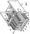
薬剤ユニット36はさらに、図2〜図5に非常に詳しく示されている分配ユニット42を含む。要するに、分配ユニット42は、キャビネット10のキャビネットフレーム12の中に挿入され得る分配ユニットフレーム44を含む。ディスペンサフレーム48へのアクセスを提供するために開かれ得る扉46が、分配ユニットフレーム44に結合されている(図3参照)。以下に非常に詳しく説明するように、様々な分配メカニズム50へのアクセスを提供するためにディスペンサフレーム48は分配ユニットフレーム44から引き出され得る(例えば図4および図5)。図2に最も良く示されるように、ディスペンサフレーム48の下に分配用引き出し52が配置されており、これはコンピュータ30によって選択された後に分配メカニズム50から落下する物品を受け取る(図1参照)。利便性のために、分配用引き出し52は、分配操作中の分配用引き出しに看護師ユーザをガイドするための照明54を含み得る。利便性のために、扉46を開けることを助けるために、扉46の上にハンドル56を備え得る(図1および図2参照)。 The
一部の事例においては、分配された物品がキャビネット10に戻される必要が生じ得る。一部の状況下においては、様々な法律および規則が、分配された物品がキャビネット10に戻されることを禁止している。そこでキャビネット10に返却ユニット58が取り付けられ得、ユニット58はその中に置かれる物品を入れるために開かれるスライド式(または回転式)の扉60を有する。物品を返却するとき、返却に関する情報がコンピュータ30に入力され得る。利便性のために、返却ユニット58上の照明62が、看護師ユーザに物品が返却され得ることを示すために点灯され得る。返却ユニット58は、ひとたび物品がユニットの中に置かれたら、再貯蔵ユーザまたは担当者が返却ユニット58へのアクセスを得る資格が与えられない限り、その物品はユニットから戻らないように、設計されることが望ましい。例えば再貯蔵担当者は、返却ユニット58を開錠して返却ユニット58の中の物品へのアクセスを許容するために、コンピュータ30に適切な情報を入力することを要求され得る。 In some cases, dispensed items may need to be returned to the
キャビネット10のある特定の配置が述べられてきたが、分配ユニット42は様々な分配キャビネットと共に使用され得ることが認識されるであろう。例えば分配ユニット42はもっぱら薬品の分配のために使用されるキャビネットの中に置かれ得、また引き出し38と同様の引き出しのみを含み得る。別の代替案としては、分配ユニット42は棚20と同様の棚のみを含むキャビネットの中に置かれ得る。さらに分配ユニット42は、上下方向に隣接して配置された複数の棚および/または引き出しを有するキャビネットの中で使用され得る。また分配キャビネットは複数の分配ユニット42を含み得る。これらは同じ寸法または異なる寸法であり得る。なお、さらに一部の事例においては、これらの分配キャビネットは、他の種類の棚、ラック、引き出し、および物品の格納を助ける類似物を含み得る。棚、ラック、および引き出しの設計の様々な例が、すでに本明細書中で参考として援用されている米国特許番号第6,272,394号、第6,385,505号、第5,805,455号、第5,805,456号、第5,745,366号、第5,905,653号、第5,927,540号、第6,039,467号、第6,151,536号、第5,377,864号、および第5,190,185号に記載されている。 Although a particular arrangement of
図2〜図6を参照することにより、分配ユニット42の構造および作動が、非常に詳しく説明される。図3に最も良く示されるように、扉46はヒンジ64を用いてフレーム44に結合される。その結果、扉46を開くことによってディスペンサフレーム48へのアクセスが得られる。利便性を考慮し、扉46の開く位置を制限するために、アーム66が使用され得、それは図4に最も良く示されるように分配用引き出し52を開けるときの妨げにはならない。利便性のために、ディスペンサフレーム48およびフレーム44は、トラックシステム68および70を含み得(そして分配用引き出し52およびフレーム44もまた同様のトラックシステムを含み得)、その結果図4に示すように分配用引き出し52およびディスペンサフレーム48がフレーム44から容易に引き出され得る。 With reference to FIGS. 2-6, the structure and operation of the dispensing
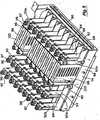
図6に最も良く示されるように、ディスペンサフレーム48は前面74、背面76、および2つの側面78および80を有する直角のフレーム72で構成される。フレーム72は前面74と背面76との間に置かれる1組の調整可能な仕切り82除いては一般に開放されている。任意ではあるが、図6に示すように別の仕切りが側面78に結合し得る。 As best shown in FIG. 6, the
前面74および背面76は、仕切り82上のタブ、突起、または類似物とかみ合うスロット、穴、溝、開口、または類似物のような1組の機械的なインターフェイスを含み得る。これによって仕切り82とフレーム72との間のブライントマタブル(blind matable)の結合が容易に生じ得る。さらにねじ84が仕切り82をフレーム72に所定位置に強固に結合するために使用され得る。一連の機械的なインターフェイスを備えることによって、ディスペンサフレーム48の中での仕切り82設置位置は、前面74から背面76まで変化し得る。さらに任意の数の仕切り82がディスペンサフレーム48に結合され得る。この方法で、仕切り82と結合される分配メカニズムの幅広い様々な配置が得られる。背面76はまた、仕切りがディスペンサフレーム48と機械的に結合されたときに仕切り82上の電気的インターフェイスと接続する一連の電気的インターフェイスを含み得る。ディスペンサフレーム48はまた回路基板86を含み(図6参照)得、それは仕切り82と関連する回路とコンピュータ30との間の通信を可能にするために使用され得る。キャビネット10と共に使用される回路の1つの能力は、ディスペンサフレーム48の内部における仕切り82の特定の配置を検出する能力である。例えば、コンピュータ30と結合された適切な回路は、仕切り82の1つがインターフェイスと接続されているかを決定するために、インターフェイスを1つづつ調べる(poll)ために使用され得る。例えば、仕切り82が特定のインタフェイスと結合されているときに発生する短絡または低電圧を感知することによって、これは検出され得る。
それ故に、分配ユニット42は、ディスペンサフレーム48の下方に置かれる分配用引き出し52と本質的に同じ幅を有する、単一のディスペンサフレームを含み得る。さらに分配用引き出し52は、分配キャビネトの中の他の引き出しおよび/または棚と、本質的に同じ幅を有し得る。このようにして、ディスペンサフレーム48を引き出すことによって全ての分配メカニズムに同時にアクセスし得る、広範囲の様々な分配メカニズムを保持するために、単一のディスペンサフレームが採用され得る。さらにディスペンサフレーム48の形態は、単にディスペンサフレーム48の中に含まれる仕切り82の形態および/数を変更することによって、容易に変化され得る。さらに、仕切り82の形態は自動的に感知され得るので、その結果、分配キャビネットは以下に詳細に説明するように、分配および/または再貯蔵の操作のために後に必要とされる、仕切りの形態を知ることになる。 Thus, the dispensing
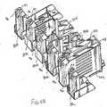
それぞれの仕切り82は、機械的インターフェイス88および分配メカニズム50を受けるために採用された電気的インターフェイス90とを含む。認識されるように、広範囲の様々な分配メカニズムが使用され得る。説明の便宜上、一般に分配メカニズムは参照番号50によって示される。特定の種類の分配メカニズムは、後ろに「a」、「b」、などを付けた同じ参照番号を使用する。例えば分配メカニズム50aは注射器形のディスペンサであり、分配メカニズム50bはカセット形のディスペンサである。利便性のために、2個の分配メカニズム50bが結合されて二重カセットディスペンサを作り得る。機械的インターフェイス88は利便性のために、ねじ止めのためのねじ切りされた開口を含み得る。また簡易開放メカニズム、移動止め、スナップ留め、他の器具を要しない結合、および類似物などの、ほかの結合用具が使用され得ることが認識される。図4に最も良く示されるように、分配メカニズム50bは仕切り82の1つにねじ92を使用してねじ止めされる。次いで、分配メカニズム50bは隣接する仕切り82まで伸長して、分配メカニズム50b上の電気的インターフェイス94が仕切り82上の電気的インターフェイス90と接続できるようにする。このようにして分配メカニズム50bは、単に分配メカニズムを適切な電気的インターフェイス90の中に押し込むこと、およびねじ92を使用して分配メカニズムを機械的インターフェイス88にねじ止めすることの、「プラグアンドプレイ」方法によって、ディスペンサフレーム48と結合され得る。同様にして他の分配メカニズムは仕切り82に接合され得る。 Each
以前に記述したように、使用され得る分配メカニズム50の数および/または寸法および/または種類を配置するために、仕切り82はいかなる形態によっても設置され得る。例えば、いくつかの特定の種類の分配メカニズムについて示されているものの、制御回路基板86を経由して電気的インターフェイス90を通過する電気信号に基づいて物品を分配することが出来る、広範囲の様々な他の分配メカニズムが使用され得ることが認識される。このような分配メカニズムの使用され得る一部の例は、すでに本明細書中で参考として援用されているアメリカ合衆国特許番号第5,377,864、および第5,190,185に記載されている。それ故に、本発明は特定の種類の分配メカニズムに限定されることを意図されるものではないことが、認識される。 As previously described, the
分配および再貯蔵の操作を制御するために、コンピュータ30(図1を参照)は各分配メカニズムの位置およびその分配メカニズムの中に貯蔵されている物品の種類を知る必要がある。ディスペンサフレーム48上の各仕切り82の位置が自動的に決定されるので、これは容易に達成され得る。同様にして、各分配メカニズムは仕切り82の1つと電気的に結合されているので、同様の調査手順を使用することによって、各分配メカニズム50の場所が決定され得る。利便性のために、各分配メカニズム50はボタン96を含み得、各仕切りの内部に置かれる回路基板によって検出され得る短絡または低電圧の信号などの、検出可能な事象を作り出すために、このボタンが再貯蔵ユーザによって押され得る。回路基板はコネクタの下方に置かれ、各分配メカニズムに対する位置情報を所有する。回路基板はまた、分配メカニズムおよびあらゆる感知メカニズムの作動を制御するために使用され得る。位置情報は回路基板からコンピュータ30に伝送され得る。このようにしてコンピュータ30は、ボタン96が押されたときの、特定の分配メカニズムの位置を知り得る。同時に、再貯蔵ユーザは該当する物品をその特定の分配メカニズムに指定し、これをコンピュータ30に入力することを得る。その結果、コンピュータ30は各分配メカニズムの位置および関連する物品の記録を所有する。利便性のために、以下にさらに詳しく説明するように、再貯蔵操作の間に再貯蔵担当者を特定の分配メカニズム50にガイドするために使用され得る照明97を、分配メカニズム50はまた含み得る。一部の事例においては、照明は仕切りの上に備えられ得、分配メカニズム50はプラスチック導管(conduit)のような光パイプを有して光を表示し得る。一部の事例においては、分配メカニズムは各分配メカニズムをユニークに識別する識別器を含み得る。この情報は回路基板によって検出され、コンピュータ30に送られ得、その結果、コンピュータ30は特定の場所に特定の分配メカニズムを指定し得る。特定の分配メカニズムが別の場所に移動させられたときには、コンピュータ30はその移動を検知し、警告信号を発し得る。使用し得る識別器の例は、RFIDタグ、EPROMチップ、バーコード、および類似品を含む。これらの識別器が使用されるときには、コンピュータ30がそれぞれの特定の分配メカニズムおよび分配メカニズムと関連するその場所を知るので、分配ユニットの形態は自動的に決定され得る。 In order to control the dispensing and re-storing operation, the computer 30 (see FIG. 1) needs to know the location of each dispensing mechanism and the type of article stored in that dispensing mechanism. This can be easily accomplished because the position of each
図3〜図5を参照することにより、分配メカニズム50aの構造が記述される。しかしながら以前に説明したように、ディスペンサフレーム48は広範囲の様々な分配メカニズムを使用することを得、本発明は特定の種類の分配メカニズムに限定されることを意図されていない。分配メカニズム50aはそれぞれ、物品を積み重ねられた状態で受け入れるように設計された開口100を有する、ハウジング98を備える。例えば、開口100は注射器を貯蔵するために利便的に使用され得る。分配メカニズム50aの底部に分配アレンジメントが置かれ、それはソレノイドによって作動し、ソレノイドが作動するごとに1個の物品を分配する。代替案としては、モータ、他の機械的アクチュエータまたは類似物によって分配が行われ得る。それ故に、コンピュータ30からの信号を受け取った後に、適切な仕切りの回路基板が、適切なソレノイド、モータまたは他の機構に信号を送り、分配アレンジメントを作動させて1個の物品を分配させることを得る。分配された物品は次いで分配用引き出し52の中に落下し、分配された物品にアクセスするために、引き出しはキャビネット10から引き出され得る。この分配アレンジメントの作動方法に関するより詳細な説明が、すでに本明細書中で参考として援用されているアメリカ合衆国特許番号第5,377,864および第5,190,185に公開されている。 With reference to FIGS. 3-5, the structure of the dispensing mechanism 50a will be described. However, as previously described, the
小ビン、アンプル、カセット、丸剤、錠剤、その他の経口固形物、および類似物などの、ほかの種類の物品を保持するために、他の分配メカニズムが使用され得ることが、認識される。例えば分配メカニズム50bは、丸剤パッケージ、小さいアンプル、小ビン、および類似物を分配するために使用され得る。分配メカニズム50bは鉛直方向に向いた出力軸を有するモータを含む。出力軸にギヤシステムが組み合わされており、ギヤシステムはハウジング305の中に収められたらせん状コイル302を軸の周りに回転させるために使用される。図5Aに最も良く示されるように、小ビン304はコイル302の間に保持され、コイル302が回転するときに下方に移動する。小ビン304がコイル302のの底に到達したときに、それは分配され、分配用引き出し52の中に落下する。それ故に、単にコンピュータ30からコイル302を回転するモータに適切な信号を送ることによって、物品は分配メカニズム50bから分配され得る。 It will be appreciated that other dispensing mechanisms can be used to hold other types of articles such as small bottles, ampoules, cassettes, pills, tablets, other oral solids, and the like. For example,
他の種類の分配メカニズムを使用するときには、回路基板86は他の種類の装置を作動する他の信号を送るように設計され得る。例えば、使用され得る他の種類の分配メカニズムは、図5Bに示される。それらは以前に述べられたものと同様の方法で、仕切り82に利便的に結合され得る。これらの分配メカニズムの1つは、分配メカニズム50bと寸法を除いては同様の、小型カセットタイプのディスペンサ50cである。分配メカニズム50cは、丸剤パケージを分配することにおいて特に有用である。別の分配メカニズムは5ml小ビンの分配メカニズム50dであり、それは分配メカニズム50aと同様の方法で、ソレノイドによって作動する。また5mlアンプルの分配メカニズム50eが示されており、それは分配メカニズム50aと同様の方法で、ソレノイドを使用することによって5mlアンプルを分配する。大型のカセット分配メカニズム50fは、丸剤パケージ、小型アンプル、および小ビンを分配するために採用される。分配メカニズム50fは、分配メカニズム50bと同様の方法で、モータによって作動し得る。 When using other types of distribution mechanisms, the
分配メカニズム50dは図5Cに非常に詳しく示されており、ソレノイドを収納するハウジング300を組み込む。その内容物を分配するために、分配メカニズム50aに関連して述べられたものと同様に、ソレノイドがトラップ扉システムを作動するために使用される。また図5Cに示されるように、分配メカニスム50dは、分配メカニズム50dが仕切りに結合されたときにコネクタ90に挿入されるように設計された、電気的コネクタ91を含む。 The dispensing mechanism 50d is shown in greater detail in FIG. 5C and incorporates a
それ故に、形態変更の可能な仕切りシステムを使用することによって、そして広範囲の様々な分配メカニズムがプラグアンドプレイの方法で接続され得るように仕切りを設計することによって、ディスペンサフレーム48は、広範囲の様々な種類と配置の分配メカニズムを配置するために、容易に形態を整えられ得る。適切な回路が各分配メカニズムの位置を容易に検出し得、この情報をコンピュータ30に供給し得ることから、仕切りの形態は自動的に決定され得、各分配メカニズムの位置は容易に指定され得、その結果物品は特定の分配メカニズムに指定され得る。限定されることを意図されるのではなく、以下の表1〜表5はディスペンサフレーム48に関して可能な様々な配置を示す。 Therefore, by using a reconfigurable partition system and by designing the partition so that a wide variety of dispensing mechanisms can be connected in a plug-and-play manner, the

分配ユニット42の他の特徴は、回路基板86がディスペンサフレーム48に組み込まれていることである。この方法において、回路基板86は、分配ユニット42からディスペンサフレーム48を単に引き出すことによって、維持、修理、または取替えのために、容易にアクセスされ得る。さらに、回路基板86をディスペンサフレーム48に組み込むことは、その仕切りを、ブラインドマタブル接続を使用し、電気コネクタに電気的に結合させることを許可する。回路基板86は、分配キャビネットとの接続において使用される他の基板へのコマンドをチャンネルする受動コネクタであり得る。これらの他の制御器は、同じ内部通信バスであり得、および、システムに、問題の多い構成要素と動作を継続させる、非機能基板での通信を除去するために利用され得る。回路基板86は、様々なリボンケーブルまたは他の通信装置を使用し、他の制御器(次にはフレーム44と結合され得、および、コンピュータ30と電気的に接続され得る)と電気的に結合され得る。これらのケーブルは、分配ユニット42に引き戻され、押し戻される場合、ディスペンサフレーム48の移動を干渉しないように、分配ユニット42側に沿ってルートされ得る。フレーム44上の制御器基板は、分配ユニット42に関連される構成要素を動作するための主制御器として使用され得る。その機能は、分配ユニット42における構成要素へ電力を操作および分配し、モジュール通信を生成し、および、分配キャビネットなどの通信バスと相互に作用することを含み得る。生成された通信は、ハードウェア構成、分配感知システムの自動較正、および、診断スクリプトの実行を含み得るが、限定されるものではない。 Another feature of the dispensing
様々なセキュリティの特徴もまた、分配ユニット42に提供され得る。例えば、図3において最良に示されるように、扉46は、フレーム44へ扉46をロックするために利用され得るラッチングメカニズムのラッチを受け取るための開口部108を含み得る。この方法において、ディスペンサフレーム48へのアクセスは、適切な識別情報がコンピュータ30へ入力されるまで、避けられ得る。そのような情報が入力された後、コンピュータ30は、ラッチングメカニズム109を動作するための信号を送信し得、扉46のロックの解除を許可し得る。 Various security features may also be provided to the dispensing
他の特徴は、物品がディスペンサの引き出し52へ落下し、物品が分配メカニズム50から分配される場合を検出するための感知システムの使用である。感知システムは、物品が分配用引き出し52へ落下する場合に解釈され得る分配メカニズムの下で、ビームまたは他の信号を伝送し得る。感知システムの一つの例示的なタイプは、IR検出器(図では隠されている)およびエミッタ111(図6を参照)を含む。IRエミッタ111は、検出器を含む対の仕切り82に指示される信号を発信するために、仕切り82のうちのもう一つに沿って配置され得る。この方法において、信号は、文字通り、それらの仕切りの間に送られる。感知システムはまた、それぞれのIRエミッタ検出器のための自動較正の特徴を持つ。較正は、分配の直前に実行され得る。そのような較正は、フレームが開いている時に周囲の光が入り込むような明るい光の間などの、光の状況が時間によって変化する場合に有益であり得る。分配の直前に較正することによって、感知システムは、異なる光の状況のもとであっても、その分配を感知するために構成され得る。一代替として、それぞれの分配メカニズムはそれ自身のセンサと関連され得、ここに記載された任意の分配メカニズムを含んでいる。この方法において、特定の分配メカニズムが物品を分配するたびに、センサはその分配を、特定の分配メカニズムに相互関連させ得る。そのような特徴を完了するための別の方法は、ディスペンサフレーム(図6において示されるように、前面74と背面76との間のような)全体の長さにわたって搭載されるエミッタおよび検出器の第2のセットを使用することによってである。この方法において、エミッタおよび検出器の二つのセットは、互いに垂直に位置される。この方法において、物品のXおよびYの位置は、物品が分配メカニズムから落下される場合、検出され得る。この情報は、物品が分配された当ディスペンサに指示するためにコンピュータ30から送信され得る。 Another feature is the use of a sensing system to detect when an article falls into the
そのような感知システムの別の実施例は、面発光レーザ(VCSEL:vertical cavity surface emitting laser)感知システムであり得る。そのようなシステムは、分配メカニズム50の下部にわたって、信号を伝送するレーザを含む。レーザは、マイクロプリズム反射器に反射するように構成されており、信号がレーザ源の近くの位置に反射され得る。信号が変化する場合、物品が分配されたことを検出するために使用され得る。そのような感知システムは、Honeywellの、VCSELレーザ感知システムであり得る。この方法において、物品がコンピュータ30での看護師ユーザによって要求された場合に、実際に分配されるように、設定がなされ得る。そのような感知システムは、較正時間を短くし、エラーを減少または除去するためにディスペンサフレーム全体にわたって感知することができる点で、利点がある。 Another example of such a sensing system may be a vertical cavity surface emitting laser (VCSEL) sensing system. Such a system includes a laser that transmits a signal across the bottom of the
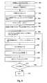
図7を参照し、ディスペンサフレーム48で構成される仕切り82の一つの方法が記載される。従来、図7において図示されるプロセスは、図1〜6に関連して図示されたように、分配キャビネット10および分配ユニット42とに関連して記載され得る。初めに再貯蔵ユーザは、コンピュータ30を使用することによってログインし得、コンピュータ30を構成モードにし得る。再貯蔵ユーザは、それゆえ、キャビネット10内のその位置が知らされるように、分配ユニット42を受け取る区域を特定し得る。仕切りを構成するために、ディスペンサフレームは、ステップ120において示されるように、アクセスされる。これは従来、分配ユニット42からディスペンサフレーム48を引き出すことによって完了され得た。この仕切りは、それゆえ、ステップ122において示されたように、所望の位置において再構成され得る。制御回路基板86は、ステップ124において示されるように、その仕切りの再構成を感知するために利用され得る。この情報は、ステップ126において示されるように、貯蔵のために、コンピュータ30へ伝送される。随意に、コンピュータ30は、再貯蔵ユーザに、感知システムが必要とならないように、その仕切りの構成を手動にて入力させるように構成され得る。 With reference to FIG. 7, one method of
図8を参照すると、ディスペンサフレーム48内の分配メカニズムを構成するための一つの方法が記載される。初めに、ステップ128において示されたように、再貯蔵ユーザは、適切な情報をコンピュータ30に入力することによって、ログインする。再貯蔵ユーザは、それゆえ、ステップ130において示されるように、コンピュータ30で、変更モードを選択し得る。随意に、分配ユニット42上の扉46は、再貯蔵ユーザが、ステップ132において示されたように、ボタンを押し扉46の施錠を解除し得るボタン57を含み得る。その際、ラッチングメカニズム109は、再貯蔵ユーザが扉を開け得るように、ラッチを外すよう動作する。ステップ134において示されるように、再貯蔵ユーザは、分配キャビネットからディスペンサフレーム48を引き得る。前記したように、本発明の一つの特徴は、再貯蔵ユーザが、分配メカニズムを再構成した場合でも、全ての仕切りに便利にアクセスし得る単一のディスペンサフレームが利用され得ることである。 Referring to FIG. 8, one method for configuring the dispensing mechanism within the
一度、ディスペンサフレームが引き出されると、再貯蔵ユーザは、ステップ136において示されるように、変更する特定の分配メカニズムを選択し得る。その変更のタイプは、分配メカニズムが仕切りに既に結合され、および単に物品の新しいタイプを割り当てられる必要があるかどうか、ならびに、分配メカニズムが、仕切りに結合される新規の分配メカニズムであるかどうかに依存し得る。この効果に関するクエリは、ステップ138において示される。分配システムが仕切りに追加される新規の分配メカニズムである場合、分配メカニズムは、ステップ140において示されるように、仕切りにインストールされる。前記したように、これは、ねじ92を機械的インターフェース88に打ち込むことによって完了され得る。ステップ142において示されるように、ボタン96は、コンピュータ30に、変更されている特定の分配メカニズムを識別するために押され得る。このプロセスは、新規、および既存の分配メカニズム両方のために実行される。ディスプレイ画面34は、再貯蔵ユーザに、ステップ144において示されるように、選択された分配メカニズムに関連された物品を選択することを許可する。コンピュータ30は、一度ボタン96が押されると、所定の仕切り上での正しい分配メカニズムを知るゆえ、その分配メカニズムに選択された物品を割り当て得る。ステップ146において示されたように、再貯蔵ユーザはまた、物品量を分配メカニズムに入力し得る。ステップ136〜146は、それゆえ、他の分配ユニットを変更するために繰り返され得る。そのプロセスが終了させられた場合、ステップ148において示されたように、ディスペンサフレームは、分配キャビネットに押し戻され得、扉が閉じられ得る。 Once the dispenser frame is withdrawn, the re-storing user may select a particular dispensing mechanism to change, as shown at
分配キャビネット10を再貯蔵するために、再貯蔵担当者は、図9のステップ150において示されるように、コンピュータ30にログインする。再貯蔵担当者は、分配ユニット42にアクセスするために認可される個人のリストと比較されるユーザ名およびパスワード情報を入力することを要求され得る。許可された場合、再貯蔵担当者は、ステップ152において示されるように、再貯蔵モードを選択し得る。コンピュータ30は、分配ユニット42において貯蔵される全ての物品の量の記録を有し得る。さらに、コンピュータ30は、薬局から受信された再貯蔵リストを含み得、そのリストは、どの物品が再貯蔵され、および、再貯蔵されるべき量を示す情報を含み得る。再貯蔵担当者は、それゆえ、ステップ154において示されるように、ディスプレイ画面34上に表示される再貯蔵リストを選択し得る。 To re-store the
一度再貯蔵リストが選択されると、ボタン57は、再貯蔵が行われるべき場所を、その再貯蔵担当者に指示するために、光り得る(および、随意には、フラッシュし得る)。ボタン57は、ステップ156において示されるように、扉46の施錠を解除するために、押され得る。扉46はそれゆえ開かれ得、ステップ158において示されるように、ディスペンサフレーム48は分配ユニット42から引き出され得る。好都合なことに、再貯蔵される必要のある分配メカニズム50上の全ての照明97は、ステップ160において示されるように、再貯蔵される必要のある分配メカニズムへ再貯蔵担当者をガイドするためにフラッシュし得る。再貯蔵担当者は、それゆえ再貯蔵されるべき分配メカニズムのうちの一つを選択し得、および、関連されるボタン96を押し得る。これは、ステップ162で示されるように、関連された照明97を、フラッシュするのを止めさせ、継続的に光らせる。コンピュータ30上のディスプレイ画面34はまた、ステップ164において示されるように、再貯蔵されている分配メカニズムに関連された物品をリストし得る。リストされた物品に関連される在庫目録情報はまた、ディスプレイ画面34に表示され得る。随意に、再貯蔵担当者は、ステップ166において示されるように、分配メカニズム50内の物品の数を確証するために尋ねられ得る。物品数の計算を容易にするために、「空のディスペンサ」アイコンはディスプレイ画面34上で選択され得、ボタン96のうちの一つは、全ての物品を分配するために押され得る。それゆえ、再貯蔵担当者は、分配メカニズムにおける物品の数を手動で計算し得、この情報をコンピュータ30に入力し得る。必要な場合、その量はコンピュータ30において変更および貯蔵され得る。しかしながら、多くの場合、数量の計算は必要なく、なぜならば、物品が分配される場合、センサが検出するからである。分配された物品が必要とされない(患者が寝ている場合など)場合、物品は感知されるが、そばのビンに戻され得る。ステップ168において示されるように、再貯蔵担当者は、分配メカニズム50へ物品を再貯蔵し得、適切な量を入力し得る。ボタン96は、それゆえ、ステップ170において示されるように、この分配メカニズムの再貯蔵が完了されることを示すために押され得る。好都合なことに、照明97は再貯蔵が完了されることを示すためにスイッチが切られ得る。ステップ172において示されるように、再貯蔵担当者は、それゆえ、追加的な分配メカニズムが再貯蔵される必要があるかどうかを決定し得る。必要がある場合、170を介してステップ162は繰り返される。必要がない場合、そのプロセスはステップ174にて終了する。再貯蔵担当者は、それゆえディスペンサフレーム48を閉め、および、扉46を閉め、鍵を閉める。 Once the re-save list is selected, the
それゆえ、再貯蔵は、分配メカニズムの全てにアクセスするために、ディスペンサフレーム48を単に引き出すことによって、容易に起こり得る。さらに、再貯蔵担当者は、再貯蔵を必要とする特定の分配メカニズムへガイドされる。好都合なことに、コンピュータ30は、再貯蔵のプロセスを容易にするために、再貯蔵情報がコンピュータ30(薬局からのように)にダウンロードされ得るように、ネットワークと接合され得る。 Therefore, re-storage can occur easily by simply pulling out the
図10はキャビネット10の分配ユニット42から分配されるアイテムのための一つの例示的方法を図示している。初めに、ステップ176において示されるように、看護師ユーザがコンピュータ30にログインする。これは、看護師ユーザが分配ユニット42に貯蔵された物品へアクセスを有し得るかどうかを決定するために、その看護師ユーザに、ユーザ名およびパスワード情報を入力することを要求し得る。ステップ178において示されたように、患者の識別情報もまた入力され得る。コンピュータ30は、それゆえ、分配モードに置かれ得、看護師ユーザは、ステップ180において示されるように、分配される薬剤を入力し得る。好都合なことに、この薬剤は、ディスプレイ画面34上に表示されるリストから選択され得る。看護師ユーザはまた、ステップ182において示されるように、服用量を入力するように要求され得る。随意に、看護師ユーザはまた、分配量を確証するために尋ねられ得る。看護師ユーザが二つ以上の物品を分配することを望む場合、そのプロセスは、ステップ180およびステップ182がそれぞれ追加される物品のために繰り返される、ステップ184へ進む。一度全ての物品が選択されると、プロセスはステップ186へ進む。 FIG. 10 illustrates one exemplary method for items dispensed from the dispensing
ステップ186において、適切な分配メカニズム50は、分配用引き出し52へ落下する薬剤の適切な量を分配する。好都合なことに、分配用引き出し52上の照明54は、ステップ188において示されるように、分配された物品を有する分配用引き出しを指示するために光り得る。看護師ユーザは、それゆえ、ステップ190において示されるように、分配用引き出し52を引き出し得、ステップ192において示されるように、分配された薬剤を取り除き得る。最後に、分配用引き出し52はステップ194において示されるように、閉じられる。 In
一部の状況において、看護師ユーザは、ステップ196において示されるように、一つ以上の物品を返却することを望み得る。望み得る場合、看護師ユーザは、ステップ198において図されるように、コンピュータ30にて返却モードを選択し得る。返却ユニット58上の照明62は、それゆえ、ステップ200において示されるように、看護師ユーザを、分配された物品を返却するための適切な場所へガイドし得る。ステップ202において示されるように、扉60は、開かれ得、物品は返却され得る。このプロセスは、ステップ204にて終了する。 In some situations, the nurse user may wish to return one or more items, as shown at
本発明は、明確な理解の目的のために詳細にわたって記載されている。しかしながら、変更および修正が、添付された請求項の範囲内にて実施され得ることが理解される。 The present invention has been described in detail for purposes of clarity of understanding. However, it will be understood that changes and modifications may be practiced within the scope of the appended claims.
Claims (30)
Translated fromJapanese前面、背面、対の側面、および、貯蔵領域を有する内部を有するキャビネットと、
該キャビネットと動作可能なように結合されるディスペンサフレームであって、複数の仕切りを含むディスペンサフレームと、
該貯蔵領域内に複数の物品を保持するように構成される複数の分配メカニズムであって、該分配メカニズムは、該ディスペンサフレームと動作可能なように結合され、該仕切りは、該複数の分配メカニズムの配置を調整することを許可するように再構成可能である、分配メカニズムと、
該ディスペンサフレームと関連し、該仕切りの構成を感知する仕切り感知システムと、
該分配メカニズムのそれぞれと関連した視覚指示器と、
該ディスペンサフレームの前に配置されるように、該キャビネットの該前面に結合される施錠可能な扉であって、該キャビネットの内部および該ディスペンサフレームへのアクセスを提供するために動作可能である扉と、
分配用引き出しであって、該分配メカニズムから分配された物品が該分配用引き出しに落下するように、該貯蔵領域の下において該キャビネットと結合される分配用引き出しと、
該分配メカニズムおよび該視覚指示器と動作可能なように結合されるコンピュータであって、該コンピュータは、再貯蔵または変更される該分配メカニズムの視覚指示器を作動するように構成され、該コンピュータは、該仕切りの構成に関する情報を記憶するように構成される、コンピュータと
を備える、装置。An apparatus for dispensing goods,
Front, rear, paired side, and, a cabinet having an interior with a savingsbuilt area,
A dispenser frame that is operatively coupled to the said cabinet, and includingMude I Supensa frame a plurality of partitions,
A plurality of dispensing mechanisms configured to hold a plurality of articles in the storage area,wherein the dispensing mechanism is operably coupled to the dispenser frame, andthe partition is formed of the plurality of dispensing mechanisms. A distribution mechanismthat is reconfigurable to allow adjustment of the arrangement of
A partition sensing system associated with the dispenser frame and sensing the configuration of the partition;
A visual indicator associated with each of the dispensing mechanisms;
To be placed in front of the dispenser frame, a lockable door that is coupled to a front surface of the cabinet,Ru operatively der to provide access to the interior and the dispenser frame of the cabinetDoor ,
A dispensing drawer, as an article dispensed from the dispensing mechanism to fall into the drawer for the distribution,amount and distribution drawerthat will be coupled with the cabinet in under said storage area,
A computer that is operatively coupled tothe said distribution mechanism and the visual indicator,the computer is configured to operate a visual indicator of the dispensing mechanism to be re-stored orchanged, the computer is And a computerconfigured to store information relating to the configuration of the partition .
分配装置を提供することであって、該分配装置は、内部を有するキャビネットと、該キャビネットと結合されるディスペンサフレームであって、該ディスペンサフレームは、複数の分配メカニズムを保持するための複数の仕切りを含み、該複数の分配メカニズムのそれぞれは、該内部において複数の物品を保持する、ディスペンサフレームと、該ディスペンサフレームと関連し、該仕切りの構成を感知する仕切り感知システムと、該ディスペンサフレームの前に配置されるように、該キャビネットの前面と結合される施錠可能な扉と、分配用引き出しであって、該分配メカニズムから分配される物品が該分配用引き出しに落下するように、該貯蔵領域の下において該キャビネットへ結合される分配用引き出しと、コンピュータとを備える、ことと、
該ディスペンサフレームにアクセスするために該扉を開くことと、
該仕切りを所望の構成に配置することと、
該仕切りの構成に関する情報を該コンピュータに供給するための信号を該仕切り感知システムから提供することと、
信号を生成するように構成される該分配メカニズムのうちの一つに関連した感知メカニズムを作動させることと、
該作動された感知メカニズムに関連した該分配メカニズムが構成されることを指示するために、該信号を該コンピュータへ送信することと
を包含する、方法。A method for configuring a dispensing device, comprising:
Providing a dispensing device, the dispensing device comprising a cabinet havingan interior and a dispenser frame coupled to the cabinet, thedispenser frame comprising a plurality of partitions for holding a plurality of dispensing mechanisms.only including,where eachof the plurality of distributionmechanism, for holding a plurality of articles in theinternal, and the dispenser frame,associated with said dispenser frame, and a partition sensing system for sensing the configuration of the partition, of the dispenser frame to be placed in front, and lockable door is coupled with the front of the cabinet, a dispensing drawer, as articles to be dispensed from the dispensing mechanism to fall into the drawer for the distribution,the storagemin and distribution drawerthat will be coupled to the cabinet in the lower region, andacomputer, this And,
Opening the door to access the dispenser frame;
Arranging the partition in a desired configuration;
Providing a signal from the partition sensing system to provide information about the configuration of the partition to the computer;
Activating a sensing mechanism associated with one of the distribution mechanisms configured to generate a signal;
To indicate that the dispensing mechanism associated with the actuatedsensing mechanism is configured, including and transmitting the signal to the computer, method.
Applications Claiming Priority (2)
| Application Number | Priority Date | Filing Date | Title |
|---|---|---|---|
| US10/434,724US6975922B2 (en) | 2003-05-08 | 2003-05-08 | Secured dispensing cabinet and methods |
| PCT/US2004/014210WO2004102492A2 (en) | 2003-05-08 | 2004-05-07 | Secured dispensing cabinet and methods |
Publications (3)
| Publication Number | Publication Date |
|---|---|
| JP2007502191A JP2007502191A (en) | 2007-02-08 |
| JP2007502191A5 JP2007502191A5 (en) | 2007-06-14 |
| JP4598773B2true JP4598773B2 (en) | 2010-12-15 |
Family
ID=33416771
Family Applications (1)
| Application Number | Title | Priority Date | Filing Date |
|---|---|---|---|
| JP2006532834AExpired - LifetimeJP4598773B2 (en) | 2003-05-08 | 2004-05-07 | Locked dispensing cabinet and method |
Country Status (7)
| Country | Link |
|---|---|
| US (3) | US6975922B2 (en) |
| EP (1) | EP1627320B1 (en) |
| JP (1) | JP4598773B2 (en) |
| AU (1) | AU2004239714B2 (en) |
| CA (1) | CA2523129C (en) |
| ES (1) | ES2632292T3 (en) |
| WO (1) | WO2004102492A2 (en) |
Families Citing this family (163)
| Publication number | Priority date | Publication date | Assignee | Title |
|---|---|---|---|---|
| US7366772B2 (en)* | 2001-06-29 | 2008-04-29 | International Business Machines Corporation | Method and apparatus for creating and exposing order status within a supply chain having disparate systems |
| US8770372B2 (en) | 2012-02-03 | 2014-07-08 | Ellenby Technologies, Inc. | Coin and bill dispensing safe |
| US6847861B2 (en) | 2001-11-30 | 2005-01-25 | Mckesson Automation, Inc. | Carousel product for use in integrated restocking and dispensing system |
| US7228198B2 (en) | 2002-08-09 | 2007-06-05 | Mckesson Automation Systems, Inc. | Prescription filling apparatus implementing a pick and place method |
| AU2003261446A1 (en)* | 2002-08-09 | 2004-02-25 | Mckesson Automation Systems, Inc. | Controller for dispensing products |
| US7052097B2 (en) | 2002-12-06 | 2006-05-30 | Mckesson Automation, Inc. | High capacity drawer with mechanical indicator for a dispensing device |
| US6975922B2 (en)* | 2003-05-08 | 2005-12-13 | Omnicell, Inc. | Secured dispensing cabinet and methods |
| US8195328B2 (en) | 2003-09-19 | 2012-06-05 | Vesta Medical, Llc | Combination disposal and dispensing apparatus and method |
| US7865263B2 (en) | 2003-11-26 | 2011-01-04 | Mckesson Automation, Inc. | Integrated suite of medical tools |
| US20050171813A1 (en)* | 2004-02-04 | 2005-08-04 | Jordan Mchael L. | System for identifying and sorting orders |
| US7395897B2 (en)* | 2004-04-09 | 2008-07-08 | Vecta Oil & Gas, Ltd. | Accelerated weight drop configurable for use as a shear wave seismic energy source and a method of operation thereof |
| US7177721B2 (en)* | 2004-11-24 | 2007-02-13 | Cerner Innovation, Inc. | Computerized method and system for loading and/or unloading a tray having a light grid over a surface thereof |
| US7146247B2 (en)* | 2004-11-24 | 2006-12-05 | Cerner Innovation, Inc. | Computerized method and system for loading and/or unloading a tray using laser scanning technology |
| US7845041B2 (en)* | 2005-05-03 | 2010-12-07 | Colgate-Palmolive Company | Interactive musical toothbrush |
| US20070023512A1 (en)* | 2005-06-10 | 2007-02-01 | Mckesson Automation Inc. | Inventory management system using rfid tags to aid in dispensing and restocking inventory |
| ITMI20051727A1 (en) | 2005-09-19 | 2007-03-20 | Bottigelli Service S R L | STORAGE AND WITHDRAWAL OF PRODUCT AND ITS MANAGEMENT PROCEDURE |
| US7747347B2 (en)* | 2005-10-03 | 2010-06-29 | Sabal Medical, Inc. | Mobile medication storage and dispensing apparatus |
| WO2007064816A2 (en) | 2005-12-02 | 2007-06-07 | Asd Specialty Healthcare, Inc. D/B/A Amerisourcebergen Specialty Group | System and method for pharmaceutical management and tracking |
| US7630791B2 (en)* | 2005-12-09 | 2009-12-08 | CareFusion 303 Inc. | System and method for storing items and tracking item usage |
| FR2898116B1 (en)* | 2006-03-06 | 2008-05-30 | Arx Sarl | MODULAR DEVICE FOR AUTOMATICALLY DISTRIBUTING AND EJECTING PRODUCTS STORED IN PARALLEL LONGITUDINAL RANGES |
| US8036773B2 (en) | 2006-05-10 | 2011-10-11 | Mckesson Automation Inc. | System, method and corresponding apparatus for storing, retrieving and delivering unit dose blisters |
| US8878676B2 (en)* | 2006-05-16 | 2014-11-04 | Gt Angel, Llc | Healthcare workstations and RFID devices for detecting medication errors |
| US7693603B2 (en) | 2007-01-22 | 2010-04-06 | John David Higham | Pharmaceutical dispensing system with coordinate guidance |
| US8251629B2 (en)* | 2007-02-09 | 2012-08-28 | Cerner Innovation, Inc. | Medication dispensing apparatus |
| US8682466B2 (en)* | 2007-05-04 | 2014-03-25 | Taiwan Semiconductor Manufacturing Company, Ltd. | Automatic virtual metrology for semiconductor wafer result prediction |
| US8009913B2 (en) | 2007-05-29 | 2011-08-30 | Mckesson Automation, Inc. | System, method, apparatus and computer program product for capturing human-readable text displayed on a unit dose package |
| US8738383B2 (en) | 2007-06-07 | 2014-05-27 | Aesynt Incorporated | Remotely and interactively controlling semi-automatic devices |
| US8280550B2 (en) | 2008-06-17 | 2012-10-02 | Omnicell, Inc. | Cabinet with remote integration |
| US10395327B2 (en)* | 2007-06-19 | 2019-08-27 | Omnicell, Inc. | Management of patient transfer systems, methods, and devices |
| US8403908B2 (en) | 2007-12-17 | 2013-03-26 | Hospira, Inc. | Differential pressure based flow sensor assembly for medication delivery monitoring and method of using the same |
| US9026370B2 (en) | 2007-12-18 | 2015-05-05 | Hospira, Inc. | User interface improvements for medical devices |
| US8094028B2 (en) | 2007-12-28 | 2012-01-10 | Mckesson Automation, Inc. | Radio frequency alignment object, carriage and associated method of storing a product associated therewith |
| US20090169138A1 (en)* | 2007-12-28 | 2009-07-02 | Mckesson Automation Inc. | Medication and medical supply storage package and method |
| US8006903B2 (en) | 2007-12-28 | 2011-08-30 | Mckesson Automation, Inc. | Proximity-based inventory management system using RFID tags to aid in dispensing and restocking inventory |
| US20090194987A1 (en)* | 2008-01-31 | 2009-08-06 | Mckesson Automation Inc. | Method, apparatus and medication storage device for efficiently generating medication labels |
| US7992746B2 (en)* | 2008-02-11 | 2011-08-09 | Carefusion 303, Inc. | Method and apparatus for removing, inserting and securing receptacles in a receptacle tray |
| US8380346B2 (en) | 2008-02-20 | 2013-02-19 | Chundy Group, LLC | System and apparatus for item management |
| US11264124B2 (en) | 2008-02-20 | 2022-03-01 | Chudy Group, LLC | System and apparatus for item management |
| ES2328656B1 (en)* | 2008-05-14 | 2010-05-25 | Microtiker, S.L | INSTALLATION FOR THE AUTOMATIC DISPENSING AND SEMIAUTOMATIC REPOSITIONING OF COMMERCIAL PRODUCTS. |
| US8065924B2 (en)* | 2008-05-23 | 2011-11-29 | Hospira, Inc. | Cassette for differential pressure based medication delivery flow sensor assembly for medication delivery monitoring and method of making the same |
| US7819838B2 (en)* | 2008-09-02 | 2010-10-26 | Hospira, Inc. | Cassette for use in a medication delivery flow sensor assembly and method of making the same |
| US20100114027A1 (en)* | 2008-11-05 | 2010-05-06 | Hospira, Inc. | Fluid medication delivery systems for delivery monitoring of secondary medications |
| US9121197B2 (en) | 2009-01-09 | 2015-09-01 | Automed Technologies, Inc. | Cabinet system with improved drawer security |
| US8103379B2 (en)* | 2009-01-09 | 2012-01-24 | Automed Technologies, Inc. | Medication cabinetry |
| US8588966B2 (en) | 2009-01-09 | 2013-11-19 | Automed Technologies, Inc. | Cabinet system |
| US8744621B2 (en) | 2009-01-09 | 2014-06-03 | Automed Technologies, Inc. | Medical cabinet access belt optimization system |
| US20100179890A1 (en)* | 2009-01-14 | 2010-07-15 | Cianciotto Jr Michael S | Tool inventory management system |
| US8048022B2 (en)* | 2009-01-30 | 2011-11-01 | Hospira, Inc. | Cassette for differential pressure based medication delivery flow sensor assembly for medication delivery monitoring and method of making the same |
| US8484049B2 (en)* | 2009-01-30 | 2013-07-09 | Omnicell, Inc. | Tissue tracking |
| US8386275B2 (en) | 2009-02-10 | 2013-02-26 | Timothy Chambers | Automatic pill dispensing device and method of use thereof |
| US7982612B2 (en) | 2009-02-20 | 2011-07-19 | Mckesson Automation Inc. | Methods, apparatuses, and computer program products for monitoring a volume of fluid in a flexible fluid bag |
| US9149405B2 (en) | 2009-03-03 | 2015-10-06 | Aesynt Incorporated | Medication storage and dispensing unit having a vial dispenser |
| US8929641B2 (en) | 2009-03-17 | 2015-01-06 | Aesynt Incorporated | System and method for determining the orientation of a unit dose package |
| US8405875B2 (en) | 2009-03-23 | 2013-03-26 | Mckesson Automation Inc. | Visibly-coded medication label and associated method, apparatus and computer program product for providing same |
| US20100249997A1 (en)* | 2009-03-25 | 2010-09-30 | Greyshock Shawn T | System, method and corresponding apparatus for detecting perforations on a unit dose blister card |
| US8400277B2 (en) | 2009-03-30 | 2013-03-19 | Mckesson Automation Inc. | Methods, apparatuses, and computer program products for monitoring a transfer of fluid between a syringe and a fluid reservoir |
| US20100263947A1 (en)* | 2009-04-20 | 2010-10-21 | Chris John Reichart | Method for generating electricity from solar panels for an electrical system inside a truck/semi/vehicle |
| US20100280486A1 (en)* | 2009-04-29 | 2010-11-04 | Hospira, Inc. | System and method for delivering and monitoring medication |
| US8267491B2 (en)* | 2009-05-07 | 2012-09-18 | Hotel Outsource Management International, Inc. | Vending machine compartment assembly |
| EP2255774A1 (en)* | 2009-05-25 | 2010-12-01 | Wiegand AG | Medicine dispenser |
| DE102009042891A1 (en)* | 2009-09-24 | 2011-03-31 | Giesecke & Devrient Gmbh | Container and system for processing banknotes |
| US8644982B2 (en) | 2009-09-30 | 2014-02-04 | Mckesson Automation Inc. | Unit dose packaging and associated robotic dispensing system and method |
| ES2335470B1 (en) | 2009-10-14 | 2010-09-27 | Grifols, S.A. | ELECTRONIC SYSTEM FOR THE MANAGEMENT OF REPLACEMENT OR FILLING OF PLANT STORES IN HOSPITALS. |
| US8869667B2 (en) | 2009-12-04 | 2014-10-28 | Aesynt Incorporated | System, method and corresponding apparatus for singulating a unit dose blister card |
| US20110161108A1 (en)* | 2009-12-30 | 2011-06-30 | Mckesson Automation Inc. | Systems and methods for detecting diversion in drug dispensing |
| US8746908B2 (en) | 2010-01-27 | 2014-06-10 | Automed Technologies, Inc. | Medical supply cabinet with lighting features |
| US8453548B2 (en) | 2010-03-23 | 2013-06-04 | Mckesson Automation Inc. | Apparatuses for cutting a unit dose blister card |
| US8640586B2 (en) | 2010-03-23 | 2014-02-04 | Mckesson Automation Inc. | Method and apparatus for facilitating cutting of a unit dose blister card |
| US8593278B2 (en) | 2010-03-29 | 2013-11-26 | Mckesson Automation Inc. | Medication storage device usage status notifications |
| US8660687B2 (en) | 2010-03-30 | 2014-02-25 | Mckesson Automation Inc. | Medication bin having an electronic display and an associated method and computer program product |
| US8527090B2 (en) | 2010-03-30 | 2013-09-03 | Mckesson Automation Inc. | Method, computer program product and apparatus for facilitating storage and/or retrieval of unit dose medications |
| US8474691B2 (en) | 2010-03-31 | 2013-07-02 | Mckesson Automation Inc. | System, apparatus, method and computer-readable storage medium for generating medication labels |
| US20120012606A1 (en) | 2010-07-14 | 2012-01-19 | Mark Longley | Automated pharmacy system for dispensing unit doses of pharmaceuticals and the like |
| US8694162B2 (en) | 2010-12-20 | 2014-04-08 | Mckesson Automation, Inc. | Methods, apparatuses and computer program products for utilizing near field communication to guide robots |
| US8662606B2 (en) | 2011-03-17 | 2014-03-04 | Mckesson Automation Inc. | Drawer assembly and associated method for controllably limiting the slideable extension of a drawer |
| US8701931B2 (en) | 2011-03-30 | 2014-04-22 | Aesynt Incorporated | Medication dispensing cabinet and associated drawer assembly having pockets with controllably openable lids |
| US8588964B2 (en) | 2011-03-30 | 2013-11-19 | Mckesson Automation Inc. | Storage devices, systems, and methods for dispensing medications |
| US8554365B2 (en) | 2011-03-31 | 2013-10-08 | Mckesson Automation Inc. | Storage devices, systems, and methods for facilitating medication dispensing and restocking |
| US9412217B2 (en) | 2011-03-31 | 2016-08-09 | Aesynt Incorporated | Medication dispensing apparatus having conveyed carriers |
| US9355220B2 (en) | 2011-05-02 | 2016-05-31 | Omnicell, Inc. | Medication dispensing cabinet systems and methods |
| US9042607B2 (en) | 2011-05-02 | 2015-05-26 | Omnicell, Inc. | System and method for user access of dispensing unit |
| US9355219B2 (en) | 2011-05-02 | 2016-05-31 | Omnicell, Inc. | Dispensing cabinet with articulating arm |
| CA2835017C (en) | 2011-05-02 | 2023-10-17 | Omnicell, Inc. | Facility-wide medication management systems |
| US8670864B2 (en) | 2011-06-27 | 2014-03-11 | Cerner Innovation, Inc. | Dynamic refill level for medication dispensing apparatus |
| AU2012299169B2 (en) | 2011-08-19 | 2017-08-24 | Icu Medical, Inc. | Systems and methods for a graphical interface including a graphical representation of medical data |
| US9910965B2 (en) | 2011-09-16 | 2018-03-06 | Aesynt Incorporated | Systems, methods and computer program product for monitoring interactions with a medication storage device |
| US9471750B2 (en) | 2011-09-23 | 2016-10-18 | Aesynt Incorporated | Systems, methods and computer program product for streamlined medication dispensing |
| US8700210B2 (en) | 2011-09-29 | 2014-04-15 | Aesynt Incorporated | Systems, methods and computer program products for visually emphasizing portions of a medication storage device |
| US8650042B2 (en) | 2011-09-30 | 2014-02-11 | Mckesson Automation Inc. | Case and medication tracking |
| US10022498B2 (en) | 2011-12-16 | 2018-07-17 | Icu Medical, Inc. | System for monitoring and delivering medication to a patient and method of using the same to minimize the risks associated with automated therapy |
| US9443370B2 (en) | 2012-03-26 | 2016-09-13 | Omnicare, Inc. | Method and apparatus for onsite distribution of medications and medical supplies |
| US8983655B2 (en) | 2012-03-26 | 2015-03-17 | Aesynt Incorporated | Automated dispensing system and method |
| JP6306566B2 (en) | 2012-03-30 | 2018-04-04 | アイシーユー・メディカル・インコーポレーテッド | Air detection system and method for detecting air in an infusion system pump |
| US8755930B2 (en) | 2012-03-30 | 2014-06-17 | Aesynt Incorporated | Method, apparatus, and computer program product for optimization of item location in an automated storage system |
| US10045909B2 (en) | 2012-03-30 | 2018-08-14 | Aesynt Incorporated | Storage apparatus with support structures |
| US8807389B2 (en) | 2012-03-30 | 2014-08-19 | Aesynt Incorporated | Item dispensing unit |
| US20130282171A1 (en)* | 2012-04-18 | 2013-10-24 | Jvm Co., Ltd. | Medicine storage apparatus |
| US8869364B2 (en) | 2012-06-25 | 2014-10-28 | Aesynt Incorporated | Material separating tool |
| US9123195B2 (en) | 2012-06-29 | 2015-09-01 | Aesynt Incorporated | Modular, multi-orientation conveyor |
| US9171246B2 (en) | 2012-06-29 | 2015-10-27 | Aesynt Incorporated | System, methods, apparatuses, and computer program products for detecting that an object has been accessed |
| US10360751B2 (en)* | 2012-07-23 | 2019-07-23 | Pharmadva, LLC | Object dispenser having a variable orifice and image identification |
| AU2013296555B2 (en) | 2012-07-31 | 2017-10-19 | Icu Medical, Inc. | Patient care system for critical medications |
| US9208635B2 (en)* | 2012-09-28 | 2015-12-08 | Innovative Product Achievements, Llc | Item dispensing apparatus |
| CN103158979A (en)* | 2012-10-11 | 2013-06-19 | 苏州艾隆科技股份有限公司 | Medicine outlet machine |
| US9150119B2 (en) | 2013-03-15 | 2015-10-06 | Aesynt Incorporated | Apparatuses, systems, and methods for anticipating and delivering medications from a central pharmacy to a patient using a track based transport system |
| US20140102859A1 (en) | 2012-10-12 | 2014-04-17 | Mckesson Automation Inc. | Apparatuses, systems, and methods for dispensing medications from a central pharmacy to a patient in a healthcare facility |
| KR102089650B1 (en) | 2012-11-19 | 2020-03-16 | 옴니셀 인코포레이티드 | Storage cabinet with multiple RFID readers |
| US9814828B2 (en) | 2013-03-15 | 2017-11-14 | Aesynt Incorporated | Method and apparatus for preparing and monitoring an intravenous fluid bag |
| US9443371B2 (en) | 2013-03-27 | 2016-09-13 | Aesynt Incorporated | Medication dispensing cabinet, computing device and associated method for measuring the force applied to a drawer |
| US9884695B2 (en) | 2013-03-28 | 2018-02-06 | Aesynt Incorporated | Compartment configured for presentation of stored articles |
| US9195803B2 (en) | 2013-03-28 | 2015-11-24 | Aesynt Incorporated | Systems, methods, apparatuses, and computer program products for providing controlled access to intravenous bags |
| US9626817B2 (en) | 2013-03-29 | 2017-04-18 | Aesynt Incorporated | Apparatuses, systems, and methods for storing and dispensing medication proximate a patient |
| US20170284732A1 (en)* | 2013-04-23 | 2017-10-05 | Minibar North America, Inc. | Controlled inventory refrigerated dispensing system |
| AU2014268355B2 (en) | 2013-05-24 | 2018-06-14 | Icu Medical, Inc. | Multi-sensor infusion system for detecting air or an occlusion in the infusion system |
| WO2014194065A1 (en) | 2013-05-29 | 2014-12-04 | Hospira, Inc. | Infusion system and method of use which prevents over-saturation of an analog-to-digital converter |
| US10166328B2 (en) | 2013-05-29 | 2019-01-01 | Icu Medical, Inc. | Infusion system which utilizes one or more sensors and additional information to make an air determination regarding the infusion system |
| US20150076973A1 (en)* | 2013-09-19 | 2015-03-19 | Donald A. PIERSON | Furniture for and method of dispensing diapers |
| US10235652B2 (en)* | 2013-09-26 | 2019-03-19 | Sonia Varrasso | Inventory control system |
| US20150133861A1 (en) | 2013-11-11 | 2015-05-14 | Kevin P. McLennan | Thermal management system and method for medical devices |
| US10984901B1 (en)* | 2013-12-18 | 2021-04-20 | Stuart Renwick Locklear | Method and system to implement medical information tracking system and medication dispenser |
| US9365315B2 (en) | 2014-01-28 | 2016-06-14 | Omnicell, Inc. | Versatile lighting system for dispensing cabinets |
| EP3110474B1 (en) | 2014-02-28 | 2019-12-18 | ICU Medical, Inc. | Infusion system and method which utilizes dual wavelength optical air-in-line detection |
| US11344673B2 (en) | 2014-05-29 | 2022-05-31 | Icu Medical, Inc. | Infusion system and pump with configurable closed loop delivery rate catch-up |
| US10143795B2 (en) | 2014-08-18 | 2018-12-04 | Icu Medical, Inc. | Intravenous pole integrated power, control, and communication system and method for an infusion pump |
| CN104443982B (en)* | 2014-10-30 | 2016-08-24 | 江苏迅捷装具科技有限公司 | Ethical goods caching rapid medicine dispensing system and method |
| US11344668B2 (en) | 2014-12-19 | 2022-05-31 | Icu Medical, Inc. | Infusion system with concurrent TPN/insulin infusion |
| US9818251B2 (en) | 2015-02-27 | 2017-11-14 | Omnicell, Inc. | Unit dose dispensing systems and methods |
| US10850024B2 (en) | 2015-03-02 | 2020-12-01 | Icu Medical, Inc. | Infusion system, device, and method having advanced infusion features |
| NZ737340A (en) | 2015-05-26 | 2019-06-28 | Icu Medical Inc | Disposable infusion fluid delivery device for programmable large volume drug delivery |
| RU2597456C1 (en)* | 2015-08-21 | 2016-09-10 | Кирилл Эдуардович Пищик | Vending machine for remote selling and method of remote selling controlled goods |
| US10427819B2 (en) | 2015-08-25 | 2019-10-01 | Chudy Group, LLC | Plural-mode automatic medicament packaging system |
| US10515722B2 (en) | 2015-10-15 | 2019-12-24 | Omnicell, Inc. | Medical equipment with diversion mechanism |
| US10685091B1 (en)* | 2016-02-02 | 2020-06-16 | PharmRight Corporation | System and method for dispensing pharmaceutical doses |
| US10186100B2 (en) | 2016-02-09 | 2019-01-22 | Omnicell, Inc. | Relay box |
| CA3023658C (en) | 2016-05-13 | 2023-03-07 | Icu Medical, Inc. | Infusion pump system and method with common line auto flush |
| WO2017214441A1 (en) | 2016-06-10 | 2017-12-14 | Icu Medical, Inc. | Acoustic flow sensor for continuous medication flow measurements and feedback control of infusion |
| US10517799B2 (en)* | 2017-08-31 | 2019-12-31 | Omnicell, Inc. | Unit dose dispensing mechanisms |
| US11735304B2 (en) | 2017-09-26 | 2023-08-22 | Mckesson Corporation | Robotic dispensary system and methods |
| US10358247B2 (en) | 2017-10-27 | 2019-07-23 | Chudy Group, LLC | Compartmentalized container loading and management system |
| US11536506B2 (en) | 2018-09-12 | 2022-12-27 | Omnicell, Inc. | Temperature controlled dispense drawer |
| US10663218B2 (en) | 2017-11-17 | 2020-05-26 | Omnicell, Inc. | Dispensing system with temperature controlled drawers |
| US10089055B1 (en) | 2017-12-27 | 2018-10-02 | Icu Medical, Inc. | Synchronized display of screen content on networked devices |
| US11348672B2 (en) | 2017-12-29 | 2022-05-31 | Cerner Innovation, Inc. | Medical order entry integration with automated dispensing systems |
| WO2019143734A1 (en)* | 2018-01-17 | 2019-07-25 | Zanghi Robert Joseph | Improvements to supply chain security |
| US10806676B2 (en) | 2018-01-30 | 2020-10-20 | Omnicell, Inc. | Relay tray |
| CN108986316A (en)* | 2018-07-24 | 2018-12-11 | 吉林工程技术师范学院 | A kind of automatic vending machine |
| MX2021003287A (en)* | 2018-09-20 | 2021-06-15 | Supplypro Inc | Modular storage system apparatus and methods. |
| CN110013409B (en)* | 2019-04-28 | 2020-08-28 | 漯河医学高等专科学校 | A drug supply device for obstetrics and gynecology care |
| EP3977379A1 (en)* | 2019-05-29 | 2022-04-06 | Ethicon, Inc. | Inventory system |
| CN110322638B (en)* | 2019-08-14 | 2024-07-09 | 山东便利客智能科技有限公司 | Automatic medicine selling machine |
| USD939079S1 (en) | 2019-08-22 | 2021-12-21 | Icu Medical, Inc. | Infusion pump |
| US11426329B2 (en)* | 2019-11-12 | 2022-08-30 | Omnicell, Inc. | Dispensing systems and methods for prefilled syringes |
| US11278671B2 (en) | 2019-12-04 | 2022-03-22 | Icu Medical, Inc. | Infusion pump with safety sequence keypad |
| US11505354B1 (en) | 2020-02-19 | 2022-11-22 | Nelson Irrigation Coporation | Packaging/inspection system for a nozzle pivot package |
| CA3189781A1 (en) | 2020-07-21 | 2022-01-27 | Icu Medical, Inc. | Fluid transfer devices and methods of use |
| CN112082306A (en)* | 2020-09-08 | 2020-12-15 | 枣庄市妇幼保健院 | Multifunctional pharmacy medicine dispensing cabinet |
| US11135360B1 (en) | 2020-12-07 | 2021-10-05 | Icu Medical, Inc. | Concurrent infusion with common line auto flush |
| USD1091564S1 (en) | 2021-10-13 | 2025-09-02 | Icu Medical, Inc. | Display screen or portion thereof with graphical user interface for a medical device |
| USD1052728S1 (en) | 2021-11-12 | 2024-11-26 | Icu Medical, Inc. | Medical fluid infusion pump |
| CA3241894A1 (en) | 2021-12-10 | 2023-06-15 | Icu Medical, Inc. | Medical fluid compounding systems with coordinated flow control |
| JP2025509154A (en) | 2022-03-08 | 2025-04-11 | エクアシールド メディカル リミテッド | Fluid transfer station in a robotic pharmaceutical preparation system |
| EP4407538B1 (en) | 2023-01-27 | 2025-07-30 | Signifi Solutions Inc. | Asset management device with automatic configuration detection |
| CN116552967B (en)* | 2023-07-11 | 2023-09-19 | 佳木斯大学 | A storage rack for medical clinical disinfectant |
Family Cites Families (53)
| Publication number | Priority date | Publication date | Assignee | Title |
|---|---|---|---|---|
| US2606803A (en)* | 1948-04-30 | 1952-08-12 | Craig Machine Inc | Vending machine |
| US2653850A (en)* | 1949-11-17 | 1953-09-29 | Theodore F Vollten | Combination storage and dispensing rack |
| US3437238A (en)* | 1967-08-28 | 1969-04-08 | Marion J Luba | Automatic butter dispenser |
| US4062385A (en)* | 1975-03-14 | 1977-12-13 | Eastman Kodak Company | Toner handling apparatus |
| US3998356A (en)* | 1975-08-28 | 1976-12-21 | Arthur A. Bennett, Jr. | Electronic system for article dispensing apparatus |
| US4225056A (en)* | 1978-09-28 | 1980-09-30 | Artag Plastics Corporation | Computerized vending machine |
| US4267942A (en)* | 1979-06-20 | 1981-05-19 | John B. Wick, Jr. | Pharmaceutical dispensing cabinet |
| US4360125A (en)* | 1980-03-10 | 1982-11-23 | Medtronic, Inc. | Medication inventory device |
| US4519522A (en)* | 1981-07-06 | 1985-05-28 | Photo Vending Corporation | Apparatus and method for storing and retrieving articles |
| DE3233559C2 (en)* | 1982-09-10 | 1984-11-29 | Agfa-Gevaert Ag, 5090 Leverkusen | Device for the light-tight introduction of a stacked film container |
| GB8323810D0 (en)* | 1983-09-06 | 1983-10-05 | Banks E J K | Supervising access to individual items |
| US4573606A (en)* | 1983-09-12 | 1986-03-04 | Kermit E. Lewis | Automatic pill dispenser and method of administering medical pills |
| US4572403A (en)* | 1984-02-01 | 1986-02-25 | Rafael Benaroya | Timed dispensing device for tablets, capsules, and the like |
| US4663621A (en)* | 1984-03-30 | 1987-05-05 | Field David J | Medicine cabinet |
| US4695954A (en)* | 1984-10-31 | 1987-09-22 | Rose Robert J | Modular medication dispensing system and apparatus utilizing portable memory device |
| JPS6392984U (en)* | 1986-12-05 | 1988-06-15 | ||
| US4814592A (en)* | 1986-05-29 | 1989-03-21 | Videomat Associates | Apparatus and method for storing and retrieving articles |
| DE3702407A1 (en)* | 1986-11-06 | 1988-05-11 | Nsm Apparatebau Gmbh Kg | RENTAL AND SALES MACHINE, ESPECIALLY FOR VIDEO CASSETTE, AND CASSETTE BOX FOR VIDEO CASSETTE |
| US4785969A (en)* | 1986-11-10 | 1988-11-22 | Pyxis Corporation | Medication dispensing system |
| SE457917B (en)* | 1987-05-19 | 1989-02-06 | Electrolux Ab | CABINET FOR SELLING DIFFERENT ARTICLES LOCATED IMAGASIN, WHICH IS LOADABLE FIXABLE IN POCKETS IN THE CABINET |
| US4847764C1 (en)* | 1987-05-21 | 2001-09-11 | Meditrol Inc | System for dispensing drugs in health care instituions |
| US4811764A (en)* | 1987-10-19 | 1989-03-14 | Mclaughlin John T | Medication dispenser station |
| SU1698598A1 (en)* | 1987-12-11 | 1991-12-15 | В.А. Васильев | Household refrigerator |
| US4967928A (en)* | 1988-06-09 | 1990-11-06 | Carter Cheryl L | Inventory control including individual patient listing and medical chart record for medication cart |
| CA2033164C (en) | 1989-05-25 | 2001-12-18 | Joseph Blechl | Drug dispensing apparatus |
| US5267174A (en)* | 1989-09-29 | 1993-11-30 | Healthtech Services Corp. | Interactive medication delivery system |
| US5190185A (en)* | 1990-05-18 | 1993-03-02 | Baxter International Inc. | Medication transport and dispensing magazine |
| JP3468790B2 (en)* | 1993-01-19 | 2003-11-17 | 健 柳沢 | Transfer device |
| US5912818A (en)* | 1993-01-25 | 1999-06-15 | Diebold, Incorporated | System for tracking and dispensing medical items |
| US5790409A (en)* | 1993-01-25 | 1998-08-04 | Medselect Systems, Inc. | Inventory monitoring and dispensing system for medical items |
| JP3354219B2 (en)* | 1993-07-07 | 2002-12-09 | 三洋電機株式会社 | Chemical storage |
| US6272394B1 (en)* | 1993-07-21 | 2001-08-07 | Omnicell.Com | Methods and apparatus for dispensing items |
| US6385505B1 (en)* | 1993-07-21 | 2002-05-07 | Omnicell.Com | Methods and apparatus for dispensing items |
| US5431299A (en)* | 1994-01-26 | 1995-07-11 | Andrew E. Brewer | Medication dispensing and storing system with dispensing modules |
| US5745366A (en)* | 1994-07-14 | 1998-04-28 | Omnicell Technologies, Inc. | Pharmaceutical dispensing device and methods |
| US5805456A (en)* | 1994-07-14 | 1998-09-08 | Omnicell Technologies, Inc. | Device and method for providing access to items to be dispensed |
| US5905653A (en)* | 1994-07-14 | 1999-05-18 | Omnicell Technologies, Inc. | Methods and devices for dispensing pharmaceutical and medical supply items |
| US6760643B2 (en)* | 1994-10-11 | 2004-07-06 | Omnicell, Inc. | Methods and apparatus for dispensing items |
| JP2933837B2 (en) | 1994-10-21 | 1999-08-16 | 株式会社湯山製作所 | Drug packaging device |
| US5797515A (en)* | 1995-10-18 | 1998-08-25 | Adds, Inc. | Method for controlling a drug dispensing system |
| US6039467A (en)* | 1996-12-05 | 2000-03-21 | Omnicell Technologies, Inc. | Lighting system and methods for a dispensing device |
| DE19728885C2 (en) | 1997-07-07 | 2000-10-19 | Reinhard Albers | Computer-based loan system |
| US5927540A (en)* | 1997-08-20 | 1999-07-27 | Omnicell Technologies, Inc. | Controlled dispensing system and method |
| US6062438A (en) | 1998-04-20 | 2000-05-16 | Mars, Inc. | Apparatus for dispensing of bulk product |
| US6151536A (en)* | 1998-09-28 | 2000-11-21 | Omnicell.Com | Dispensing system and methods |
| US6481180B1 (en) | 1999-05-20 | 2002-11-19 | Sanyo Electric Co., Ltd. | Solid preparation filling apparatus |
| US6564121B1 (en)* | 1999-09-22 | 2003-05-13 | Telepharmacy Solutions, Inc. | Systems and methods for drug dispensing |
| US6658322B1 (en)* | 2000-05-05 | 2003-12-02 | Medselect Inc. | System and method for tracking medical items and supplies |
| WO2003074396A1 (en)* | 2002-03-04 | 2003-09-12 | Alexandre Maldonado | Adjustable push forward dispensing mechanism |
| JP2002156181A (en)* | 2000-11-16 | 2002-05-31 | Yozan Inc | refrigerator |
| JP4617011B2 (en) | 2001-03-13 | 2011-01-19 | 株式会社湯山製作所 | Drug storage device |
| JP2002282342A (en)* | 2001-03-26 | 2002-10-02 | Naka Instruments Co Ltd | Drug controlling system |
| US6975922B2 (en)* | 2003-05-08 | 2005-12-13 | Omnicell, Inc. | Secured dispensing cabinet and methods |
- 2003
- 2003-05-08USUS10/434,724patent/US6975922B2/ennot_activeExpired - Lifetime
- 2004
- 2004-05-07AUAU2004239714Apatent/AU2004239714B2/ennot_activeExpired
- 2004-05-07ESES04751552.3Tpatent/ES2632292T3/ennot_activeExpired - Lifetime
- 2004-05-07EPEP04751552.3Apatent/EP1627320B1/ennot_activeExpired - Lifetime
- 2004-05-07JPJP2006532834Apatent/JP4598773B2/ennot_activeExpired - Lifetime
- 2004-05-07WOPCT/US2004/014210patent/WO2004102492A2/enactiveApplication Filing
- 2004-05-07CACA2523129Apatent/CA2523129C/ennot_activeExpired - Lifetime
- 2005
- 2005-08-17USUS11/206,660patent/US7571024B2/ennot_activeExpired - Lifetime
- 2009
- 2009-07-02USUS12/496,746patent/US7835819B2/ennot_activeExpired - Lifetime
Also Published As
| Publication number | Publication date |
|---|---|
| CA2523129C (en) | 2013-01-29 |
| JP2007502191A (en) | 2007-02-08 |
| WO2004102492A3 (en) | 2005-08-18 |
| EP1627320B1 (en) | 2017-04-05 |
| US6975922B2 (en) | 2005-12-13 |
| AU2004239714B2 (en) | 2011-02-03 |
| CA2523129A1 (en) | 2004-11-25 |
| WO2004102492A2 (en) | 2004-11-25 |
| EP1627320A4 (en) | 2006-07-05 |
| US7835819B2 (en) | 2010-11-16 |
| US20060085094A1 (en) | 2006-04-20 |
| US7571024B2 (en) | 2009-08-04 |
| EP1627320A2 (en) | 2006-02-22 |
| ES2632292T3 (en) | 2017-09-12 |
| US20100070074A1 (en) | 2010-03-18 |
| AU2004239714A1 (en) | 2004-11-25 |
| US20040225409A1 (en) | 2004-11-11 |
Similar Documents
| Publication | Publication Date | Title |
|---|---|---|
| JP4598773B2 (en) | Locked dispensing cabinet and method | |
| US12171695B2 (en) | Medical technology station and method of use | |
| US6788997B1 (en) | Medical cabinet with adjustable drawers | |
| US6985797B2 (en) | Method of operating a dispensing cabinet | |
| US6112502A (en) | Restocking method for medical item dispensing system | |
| JP3751317B2 (en) | Storage unit used to distribute goods | |
| US5912818A (en) | System for tracking and dispensing medical items | |
| CA2412760C (en) | Dispensing cabinet with unit dose dispensing drawer | |
| EP2827740B1 (en) | Medication dispensing apparatus having drawer assembly with discrete compartments | |
| US8423180B1 (en) | System for tracking and dispensing medical items from environmentally controlled storage area | |
| CN117383056A (en) | Unit dose dispensing system and method | |
| HK40055425A (en) | A medical technology station and method of use | |
| HK1261219B (en) | A medical technology station and method of use | |
| HK1261219A1 (en) | A medical technology station and method of use | |
| JPH0747106A (en) | Medicine managing storage box |
Legal Events
| Date | Code | Title | Description |
|---|---|---|---|
| A521 | Request for written amendment filed | Free format text:JAPANESE INTERMEDIATE CODE: A523 Effective date:20070416 | |
| A621 | Written request for application examination | Free format text:JAPANESE INTERMEDIATE CODE: A621 Effective date:20070416 | |
| A131 | Notification of reasons for refusal | Free format text:JAPANESE INTERMEDIATE CODE: A131 Effective date:20091202 | |
| A601 | Written request for extension of time | Free format text:JAPANESE INTERMEDIATE CODE: A601 Effective date:20100301 | |
| A602 | Written permission of extension of time | Free format text:JAPANESE INTERMEDIATE CODE: A602 Effective date:20100308 | |
| A521 | Request for written amendment filed | Free format text:JAPANESE INTERMEDIATE CODE: A523 Effective date:20100402 | |
| TRDD | Decision of grant or rejection written | ||
| A01 | Written decision to grant a patent or to grant a registration (utility model) | Free format text:JAPANESE INTERMEDIATE CODE: A01 Effective date:20100830 | |
| A01 | Written decision to grant a patent or to grant a registration (utility model) | Free format text:JAPANESE INTERMEDIATE CODE: A01 | |
| A61 | First payment of annual fees (during grant procedure) | Free format text:JAPANESE INTERMEDIATE CODE: A61 Effective date:20100924 | |
| R150 | Certificate of patent or registration of utility model | Ref document number:4598773 Country of ref document:JP Free format text:JAPANESE INTERMEDIATE CODE: R150 Free format text:JAPANESE INTERMEDIATE CODE: R150 | |
| FPAY | Renewal fee payment (event date is renewal date of database) | Free format text:PAYMENT UNTIL: 20131001 Year of fee payment:3 | |
| R250 | Receipt of annual fees | Free format text:JAPANESE INTERMEDIATE CODE: R250 | |
| R250 | Receipt of annual fees | Free format text:JAPANESE INTERMEDIATE CODE: R250 | |
| R250 | Receipt of annual fees | Free format text:JAPANESE INTERMEDIATE CODE: R250 | |
| R250 | Receipt of annual fees | Free format text:JAPANESE INTERMEDIATE CODE: R250 | |
| R250 | Receipt of annual fees | Free format text:JAPANESE INTERMEDIATE CODE: R250 | |
| R250 | Receipt of annual fees | Free format text:JAPANESE INTERMEDIATE CODE: R250 | |
| R250 | Receipt of annual fees | Free format text:JAPANESE INTERMEDIATE CODE: R250 | |
| R250 | Receipt of annual fees | Free format text:JAPANESE INTERMEDIATE CODE: R250 | |
| R250 | Receipt of annual fees | Free format text:JAPANESE INTERMEDIATE CODE: R250 | |
| R250 | Receipt of annual fees | Free format text:JAPANESE INTERMEDIATE CODE: R250 | |
| R250 | Receipt of annual fees | Free format text:JAPANESE INTERMEDIATE CODE: R250 | |
| EXPY | Cancellation because of completion of term |