JP4598611B2 - Sample preparation apparatus and sample preparation analysis system - Google Patents
Sample preparation apparatus and sample preparation analysis systemDownload PDFInfo
- Publication number
- JP4598611B2 JP4598611B2JP2005184196AJP2005184196AJP4598611B2JP 4598611 B2JP4598611 B2JP 4598611B2JP 2005184196 AJP2005184196 AJP 2005184196AJP 2005184196 AJP2005184196 AJP 2005184196AJP 4598611 B2JP4598611 B2JP 4598611B2
- Authority
- JP
- Japan
- Prior art keywords
- specimen
- slide glass
- stained
- cassette
- preparation
- Prior art date
- Legal status (The legal status is an assumption and is not a legal conclusion. Google has not performed a legal analysis and makes no representation as to the accuracy of the status listed.)
- Expired - Fee Related
Links
Images


Landscapes
- Investigating Or Analysing Biological Materials (AREA)
- Sampling And Sample Adjustment (AREA)
Description
Translated fromJapanese本発明は、標本作製装置および標本作製分析システムに関し、特に、スライドガラス上に標本を作製する標本作製装置および標本作製分析システムに関する。The present invention relatesto a slide preparing apparatusand sample preparation analysissystem, in particular, it relatesto a sample preparation deviceand specimen preparation analysissystem to produce a specimen on a slide glass.
従来、標本作製装置として、スライドガラス上に血液を塗抹することにより、血液の標本を作製する血液塗抹標本作製装置が知られている(たとえば、特許文献1参照)。上記特許文献1には、スライドガラスへの血液の塗抹から染色工程までを自動的に行う血液塗抹標本作製装置が開示されている。この特許文献1の血液塗抹標本作製装置では、染色済みのスライドガラス(標本)が収納されたカセットは、血液塗抹標本作製装置内に設けられた保管部に保管される。 2. Description of the Related Art Conventionally, a blood smear preparation apparatus that prepares a blood specimen by smearing blood on a slide glass is known as a specimen preparation apparatus (see, for example, Patent Document 1). Patent Document 1 discloses a blood smear preparation apparatus that automatically performs the process from smearing blood on a slide glass to a staining step. In the blood smear preparation apparatus of Patent Document 1, a cassette storing a stained slide glass (specimen) is stored in a storage unit provided in the blood smear preparation apparatus.
また、従来、標本分析装置として、血液の標本をデジタル的に画像処理することにより、血球の分類を自動的に行う血液細胞自動分析装置が知られている。この血液細胞自動分析装置では、上記した血液塗抹標本作製装置で作製した標本を分析することが可能である。なお、血液細胞自動分析装置を用いて血液塗抹標本作製装置で作製した標本を分析する場合、従来では、血液塗抹標本作製装置の保管部に保管されたカセットに収納された染色済みのスライドガラス(標本)を、作業者が抜き取って、血液細胞自動分析装置専用マガジンにスライドガラスを収納して、血液細胞自動分析装置にマガジンをセットするのが一般的である。 Conventionally, as a sample analyzer, an automatic blood cell analyzer that automatically classifies blood cells by digitally processing a blood sample is known. With this blood cell automatic analyzer, it is possible to analyze a specimen prepared with the above-described blood smear preparation apparatus. In the case of analyzing a specimen prepared with a blood smear preparation apparatus using an automatic blood cell analyzer, conventionally, a stained slide glass stored in a cassette stored in a storage section of the blood smear preparation apparatus ( In general, an operator removes a specimen), puts a slide glass in a magazine dedicated to an automatic blood cell analyzer, and sets the magazine in the automatic blood cell analyzer.
しかしながら、血液細胞自動分析装置を用いて血液塗抹標本作製装置で作製した標本を分析する場合において、作業者が染色済みのスライドガラス(標本)を血液塗抹標本作製装置に保管されたカセットから抜き取ってマガジンに収納し、そのマガジンを血液細胞自動分析装置にセットする従来の方法では、作業者の負担が大きくなるという問題点があった。 However, when analyzing a specimen prepared with a blood smear preparation apparatus using an automatic blood cell analyzer, an operator removes a stained slide glass (specimen) from a cassette stored in the blood smear preparation apparatus. The conventional method of storing in a magazine and setting the magazine in an automatic blood cell analyzer has a problem of increasing the burden on the operator.
この発明は、上記のような課題を解決するためになされたものであり、作業者に負担をかけることなく、標本作製装置から標本分析装置への標本の供給動作を行うことが可能な標本作製装置および標本作製分析システムを提供することを目的とする。 The present invention has been made to solve the above-described problems, and is capable of performing a sample supply operation from a sample preparation device to a sample analysis device without burdening an operator. An object is to provide an apparatus and a specimen preparation analysis system.
上記目的を達成するために、この発明の第1の局面による標本作製装置は、スライドガラス上に標本を作製して染色するとともに、染色標本が作製された染色標本スライドガラスを外部装置に供給可能な標本作製装置であって、スライドガラス上に標本を作製して染色する染色標本作製部と、染色標本作製部で作製された染色標本スライドガラスを収容する保管部と、保管部または外部装置へ染色標本スライドガラスを供給するための搬送部と、標本作製装置と通信可能に接続されたコンピュータから標本情報を取得し、標本情報が目視用標本の作製指示である場合、染色標本スライドガラスを保管部へ供給し、標本情報が標本分析装置用標本の作製指示である場合、染色標本スライドガラスを外部装置へ供給するように搬送部を制御する制御部とを備えている。In order to achieve the above object, the specimen preparation device according to the first aspect of the present invention can prepare and stain a specimen on a slide glass and supply the stained specimen slide glass on which the stained specimen is prepared to an external device To a specimen preparation device that prepares and stains a specimen on a slide glass, a storage section that houses a stained specimen slide glass prepared by the specimen preparation section, and astorage section or an external device Obtain specimen information from a transport unit for supplying stained specimen slide glass and a computer connected to the specimen preparation device in a communicable manner, and store the specimen specimen slide glass when the specimen information is a visual specimen preparation instruction. supplied to the parts, when the sample information is produced instruction specimen specimen analyzer, controls the transport unit so as to supply the stained specimen slides to the external device control And a part.
この第1の局面による標本作製装置では、上記のように、染色標本スライドガラスを保管部および外部装置のいずれに供給するかを決定する制御部を設けることによって、その制御部により、染色標本作製部で作製された染色標本スライドガラスの供給先を自動的に決定することができる。これにより、標本作製装置に染色標本スライドガラスを搬送するための搬送部を設けた場合には、その搬送部を制御部により制御することによって、作業者に負担をかけることなく、染色標本作製部から標本作製装置の保管部または標本分析装置などの外部装置への標本の供給動作を行うことができる。また、制御部により搬送部を制御することによって、容易に、作業者に負担をかけることなく、染色標本作製部から標本作製装置の保管部または標本分析装置などの外部装置への標本の供給動作を行うことができる。また、標本情報に基づいて、標本の供給動作を行うことができる。また、目視用の染色標本スライドガラスを標本作製装置の保管部へ供給するとともに、標本分析装置用の染色標本スライドガラスを外部装置へ供給する場合において、容易に、制御部により標本作製装置を制御することによって、染色標本スライドガラスを、標本作製装置の保管部と外部装置とに振り分けることができる。In the specimen preparation apparatus according to the first aspect, as described above, by providing a control section that determines whether the stained specimen slide glass is supplied to the storage section or the external apparatus, the control section prepares the stained specimen preparation. The supply destination of the stained specimen slide glass produced in the section can be automatically determined. Thereby, when the specimen preparation apparatus is provided with a transport section for transporting the stained specimen slide glass, the control section is controlled by the control section, so that the stained specimen preparation section is not burdened on the operator. The specimen can be supplied to an external device such as a specimen preparation apparatus storage unit or specimen analyzer.In addition, by controlling the transport unit by the control unit, it is easy to supply the sample from the stained sample preparation unit to the storage unit of the sample preparation device or an external device such as a sample analyzer without burdening the operator. It can be performed. Further, a sample supply operation can be performed based on the sample information. In addition, when the stained specimen slide glass for visual observation is supplied to the storage section of the specimen preparation apparatus, and when the specimen specimen slide glass for specimen analyzer is supplied to the external apparatus, the specimen preparation apparatus is easily controlled by the control section. By doing so, the stained specimen slide glass can be distributed to the storage section of the specimen preparation apparatus and the external apparatus.
上記第1の局面による標本作製装置において、好ましくは、外部装置が、供給された染色標本スライドガラスを保管するとともに保管した染色標本スライドガラスを標本分析装置に供給可能な標本保管供給装置である。In the sample preparation device according to the first aspect, preferably, theexternal device is a sample storage and supply device capable of storing the supplied stained sample slide glass and supplying the stored stained sample slide glass to the sample analyzer.
上記第1の局面による標本作製装置において、好ましくは、外部装置が標本分析装置である。In the specimen preparation device according to the first aspect, theexternal device is preferably aspecimen analyzer.
上記外部装置が標本保管供給装置であるかまたは外部装置が標本分析装置である構成において、好ましくは、標本分析装置が、標本作製装置で作製された染色標本スライドガラスを分析するための分析手段と、染色標本スライドガラスが有する識別情報を検知する識別情報検知手段とを備える。In the configuration in which the external device is a sample storage and supply device or the external device is a sample analysis device , preferably, thesample analysis device includesan analysis means for analyzing the stained sample slide glass prepared by the sample preparation device. And an identification information detecting means for detecting the identification information of the stained specimen slide glass.
上記第1の局面による標本作製装置において、好ましくは、スライドガラスの所定の位置に標本情報を印字するための印字部をさらに備える。このように構成すれば、印字部によりスライドガラスの所定の位置に標本情報を印字することによって、容易に、スライドガラスの所定の位置に印字された標本情報に基づいて、標本の供給動作を行うことができる。Thespecimen preparation device according to the first aspect preferably further includes a printing unit for printing specimen information at a predetermined position of the slide glass. If comprised in this way, the sample supply operation | movement will be easily performed based on the sample information printed on the predetermined position of the slide glass by printing the sample information on the predetermined position of the slide glass by the printing unit. be able to.
この発明の第2の局面による標本作製分析システムは、スライドガラス上に標本を作製して染色し、染色標本スライドガラスを作製するとともに、染色標本スライドガラスを保管するための第1保管部を有する標本作製手段と、染色標本スライドガラスを分析する標本分析手段と、標本作製手段で作製された染色標本スライドガラスを保管するための第2保管部と、染色標本スライドガラスを標本分析手段に供給するための供給部とを有する標本保管供給手段と、染色標本スライドガラスを第1保管部へ保管するか標本保管供給手段へ供給するか決定するための標本情報を有するコンピュータと、を備え、標本作製手段は、コンピュータから取得した標本情報が目視用標本の作製指示である場合、染色標本スライドガラスを第1保管部へ保管し、標本情報が標本分析手段用標本の作製指示である場合、染色標本スライドガラスを標本保管供給手段へ供給を行う。The specimen preparation analysis system according to the second aspect of the present invention prepares and stains a specimen on a slide glass to produce astained specimen slide glass and has a first storage section for storing the stained specimen slide glass. Specimen preparation means, specimen analysis means for analyzing stained specimen slide glass,second storage unit for storing stained specimen slide glass prepared by specimen preparation means, and supply of stained specimen slide glass to specimen analysis means It includes a sample storage supply means having a supplyfor, and a computer having a sample information for determining whether to supply the stained specimen slides to either sample storage supply means for storing the first storageunit,sample preparing The means stores the stained specimen slide glass in the first storage section when the specimen information acquired from the computer is an instruction to produce a specimen for visual observation. If the sample information is produced instruction specimen specimen analyzing means, to supply the stained specimen slides to the sample storage supply means.
この第2の局面による標本作製分析システムでは、上記のように、標本作製手段で作製された染色標本スライドガラスを保管するための第2保管部と、染色標本スライドガラスを標本分析手段に供給するための供給部とを有する標本保管供給手段を設けることによって、標本保管供給手段により、標本作製手段から標本分析手段への染色標本スライドガラスの供給動作を自動的に行うことができる。これにより、作業者に負担をかけることなく、標本作製手段から標本分析手段への染色標本スライドガラスの供給動作を行うことができる。また、コンピュータが有する標本情報に基づいて、染色標本スライドガラスの保管または供給先を自動的に決定することができる。また、容易に、標本作製手段により、標本情報に基づいて、染色標本スライドガラスの保管または供給先を自動的に決定することができる。また、目視用の染色標本スライドガラスを標本作製手段の第1保管部へ保管するとともに、標本分析手段用の染色標本スライドガラスを標本保管供給手段へ供給する場合において、容易に、標本作製手段により、染色標本スライドガラスを、標本作製手段の第1保管部と標本分析手段とに振り分けることができる。In the specimen preparation analysis system according to the second aspect, as described above, thesecond storage section for storing the stained specimen slide glass prepared by the specimen preparation means and the stained specimen slide glass are supplied to the specimen analysis means. By providing the specimen storage / supply means having the supply section for supplying the stained specimen slide glass from the specimen preparation means to the specimen analysis means can be automatically performed by the specimen storage / supply means. Thereby, the supply operation of the stained specimen slide glass from the specimen preparation means to the specimen analysis means can be performed without imposing a burden on the operator.Further, the storage or supply destination of the stained specimen slide glass can be automatically determined based on the specimen information that the computer has. Moreover, the storage or supply destination of the stained specimen slide glass can be automatically determined by the specimen preparation means based on the specimen information. In addition, when the stained specimen slide glass for visual observation is stored in the first storage unit of the specimen preparation means, and when the stained specimen slide glass for specimen analysis means is supplied to the specimen storage supply means, the specimen preparation means can easily The stained specimen slide glass can be distributed to the first storage part of the specimen preparation means and the specimen analysis means.
上記第2の局面による標本作製分析システムにおいて、好ましくは、標本作製手段は、前記染色標本スライドガラスが有する識別情報を検知する識別情報検知手段を備える。In the specimen preparation analysis system according to the second aspect, the specimen preparation means preferably includesidentification information detection means for detecting identification information of the stained specimen slide glass.
上記第2の局面による標本作製分析システムにおいて、好ましくは、標本作製手段は、スライドガラスの所定の位置に標本情報を印字するための印字部を有する。このように構成すれば、印字部によりスライドガラスの所定の位置に標本情報を印字することによって、容易に、スライドガラスの所定の位置に印字された標本情報に基づいて、標本の供給動作を行うことができる。In thesample preparation / analysis system according to the second aspect , preferably, the sample preparation means has a printing unit for printing sample information at a predetermined position of the slide glass. If comprised in this way, the sample supply operation | movement will be easily performed based on the sample information printed on the predetermined position of the slide glass by printing the sample information on the predetermined position of the slide glass by the printing unit. be able to.
以下、本発明の実施形態を図面に基づいて説明する。 Hereinafter, embodiments of the present invention will be described with reference to the drawings.
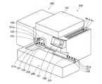
図1は、本発明の一実施形態による標本作製分析システムの全体構成を示した斜視図であり、図2は、図1に示した一実施形態による標本作製分析システムの概略図である。図3は、図1に示した一実施形態による標本作製分析システムの内部構造の平面図である。また、図4は、図1に示した一実施形態による標本作製分析システムに用いるスライドガラスのフロスト部の拡大図であり、図5および図6は、図1に示した一実施形態による標本作製分析システムに用いるカセットおよびスライドガラスの斜視図である。また、図7〜図17は、図1に示した一実施形態による標本作製分析システムの標本作製装置の構造を示した詳細図である。まず、図1〜図3を参照して、本実施形態による標本作製分析システムの全体構成について説明する。 FIG. 1 is a perspective view showing an overall configuration of a specimen preparation analysis system according to an embodiment of the present invention, and FIG. 2 is a schematic diagram of the specimen preparation analysis system according to the embodiment shown in FIG. FIG. 3 is a plan view of the internal structure of the specimen preparation analysis system according to the embodiment shown in FIG. 4 is an enlarged view of a frosted portion of a slide glass used in the specimen preparation analysis system according to the embodiment shown in FIG. 1, and FIGS. 5 and 6 show specimen preparation according to the embodiment shown in FIG. It is a perspective view of the cassette and slide glass used for an analysis system. 7 to 17 are detailed views showing the structure of the sample preparation device of the sample preparation analysis system according to the embodiment shown in FIG. First, with reference to FIGS. 1-3, the whole structure of the sample preparation analysis system by this embodiment is demonstrated.
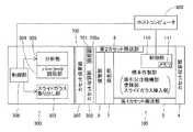
本実施形態の標本作製分析システムは、図1に示すように、血液塗抹標本作製装置100と、搬送装置200と、血液細胞自動分析装置300とを備えている。なお、血液細胞自動分析装置300は、血液塗抹標本作製装置100で作製された標本を、デジタル画像処理するとともに、自動的に血球の分類を行う装置である。また、血液塗抹標本作製装置100は、血液細胞自動分析装置300により分析することが可能な自動分析用の標本と、目視により分析することが可能な目視用の標本との2種類の標本を作製する装置である。搬送装置200は、血液塗抹標本作製装置100の前面に設置されているとともに、血液細胞自動分析装置300は、血液塗抹標本作製装置100の一方の側面に設置されている。また、図2に示すように、血液塗抹標本作製装置100の制御部110には、ホストコンピュータ400が接続されている。 As shown in FIG. 1, the sample preparation / analysis system of the present embodiment includes a blood
搬送装置200は、図1に示すように、血液が収容された試験管151を収納する検体ラック150を血液塗抹標本作製装置100に自動的に搬送するために設けられている。また、血液塗抹標本作製装置100は、タッチパネルからなる表示操作部101と、起動スイッチ102と、電源スイッチ103と、カバー104とを含んでいる。また、血液塗抹標本作製装置100には、血液が収容された試験管151を搬送装置200側から血液塗抹標本作製装置100側に搬送するためのハンド部材160が設けられている。血液が収容された試験管151には、ゴム栓151aが装着されている。 As shown in FIG. 1, the
また、血液塗抹標本作製装置100は、図3に示すように、吸引分注機構部1と、塗抹部2と、樹脂製のカセット3と、カセット収容部4と、第1カセット搬送部5と、スライドガラス挿入部6と、染色部7と、第2カセット搬送部8と、保管部9とを備えている。吸引分注機構部1は、ハンド部材160(図1参照)によって血液塗抹標本作製装置100側に搬送された試験管151から血液を吸引するとともに、吸引した血液をスライドガラス10に滴下する機能を有する。この吸引分注機構部1は、図3に示すように、試験管151から血液を吸引するためのピアサ(吸引針)1aと、吸引した血液をスライドガラス10に分注するためのピペット1bと、ピアサ1aおよびピペット1bに接続されるシリンジポンプ1cと、ピアサ1aとシリンジポンプ1cとの間の流路を開閉するためのバルブ1dと、ピペット1bとシリンジポンプ1cとの間の流路を開閉するためのバルブ1eとを含んでいる。 In addition, as shown in FIG. 3, the blood
ここで、本実施形態では、吸引分注機構部1は、2枚のスライドガラス10の各々に同一の血液(検体)を分注するとともに、その血液の分注量を、自動分析用の標本に対応した量と、目視用の標本に対応した量とに調節する機能を有する。 Here, in the present embodiment, the suction dispensing mechanism unit 1 dispenses the same blood (specimen) into each of the two
塗抹部2は、スライドガラス10を分注・塗抹位置20に供給するとともに、スライドガラス10に滴下された血液を塗抹して乾燥し、かつ、スライドガラス10に印字を行うために設けられている。この塗抹部2には、スライドガラス供給部2aと、スライドガラス収納部2bと、引きガラス2cと、送りベルト2dおよび2eと、ファン2fと、印字部2gと、スライドガラス搬送部2hとが設けられている。 The smearing unit 2 is provided for supplying the
また、スライドガラス供給部2aは、2つのスライドガラス収納部2bに収納されたスライドガラス10を、図示しない取出機構および送りベルト2dに取り付けられた図示しないチャックを用いて、送りベルト2e上に供給する機能を有する。送りベルト2eは、スライドガラス10を分注・塗抹位置20および乾燥位置21aおよび21bに搬送するように構成されている。引きガラス2cは、分注・塗抹位置20でスライドガラス10に分注された血液を塗抹することができるように、スライドガラス10に当接する位置に移動可能で、かつ、スライドガラス10の長手方向に移動可能に構成されている。ファン2fは、乾燥位置21aおよび21bに搬送されたスライドガラス10の塗抹された血液を乾燥するために設けられている。 Further, the slide
ここで、本実施形態では、印字部2gは、熱転写プリンタからなる。そして、印字部2gは、図4に示すように、スライドガラス10のフロスト部(情報表示領域)10aに、検体番号、日付、受付番号および氏名などの標本情報が蓄積された2次元バーコード10bと、標本情報に含まれる属性情報としての日付(07/06/04)10c、名前(Sysmex)10dおよび検体番号(BA15617)10eからなる3行のテキストデータとを印字するために設けられている。なお、2次元バーコードとは、平面的に見て水平方向と垂直方向との2方向に情報を保持したバーコードである。また、スライドガラス10のフロスト部10aに印字する2次元バーコード10bとしては、データマトリックスやQRコードなどがある。また、2次元バーコード10bの情報量(蓄積可能な文字数)は、半角文字で最大50桁であり、全角文字で最大25桁である。 Here, in the present embodiment, the
また、印字部2g(熱転写プリンタ)のインクとしては、スライドガラス10のフロスト部10aに印字される2次元バーコード10bおよびテキストデータ(10c〜10e)が、染色操作および顕微鏡検査の際に用いるアルコールやキシレンなどの有機溶媒によって溶出しないような耐久性を有するインクが用いられる。 In addition, as the ink for the
また、本実施形態では、図4および図5に示すように、スライドガラス10のフロスト部(情報表示領域)10は、スライドガラス10の長手方向において標本作製領域10fと隣接するように、スライドガラス10の一方の端部側の領域に配置されている。また、フロスト部10aの2次元バーコード10bが印字されるバーコード印字領域F1および3行のテキストデータ(10c〜10e)が印字されるテキスト印字領域F2は、スライドガラス10の短手方向に互いに隣接するように配置されている。また、2次元バーコード10bは、平面的に見て正方形状を有する。また、3行のテキストデータ(10c〜10e)の各々は、バーコード印字領域F1とテキスト印字領域F2とのスライドガラス10の長手方向の長さが同じになるように、スライドガラス10の長手方向に互いに所定の間隔を隔てて隣接するように配置されている。また、3行のテキストデータ(10c〜10e)の各々を構成する文字および数字は、スライドガラス10の短手方向に沿って配列されている。この場合の印字可能なテキストデータの文字数は、半角文字で最大8文字である。 In the present embodiment, as shown in FIGS. 4 and 5, the frosted portion (information display area) 10 of the
また、本実施形態では、スライドガラス10のフロスト部10aに対応する領域上には、樹脂などのコーティング剤からなる印字可能なコーティング膜10gが形成されている。このコーティング膜10gを構成するコーティング剤は、染色操作および顕微鏡検査の際に用いるアルコールやキシレンなどの有機溶媒に対して優れた耐久性を有する。そして、上記した2次元バーコード10bおよび3行のテキストデータ(10c〜10e)は、フロスト部10aに位置するコーティング膜10gの上面上に印字されている。また、コーティング膜10gは、標本作製領域10fを挟むように、フロスト部10aからスライドガラス10の長手方向に沿って延びるように形成されている。 In the present embodiment, a
また、図3に示すように、スライドガラス搬送部2hは、スライドガラス10を送りベルト2eの端部から印字部2gへ移動させるとともに、印字後のスライドガラス10をカセット3の収納位置へ移動させるために設けられている。このスライドガラス搬送部2hは、スライドガラス10を送りベルト2eの端部から印字のための横方向位置21cへ横方向(図3のX方向)に移動させるための横方向移動片2iと、スライドガラス10を印字のための縦方向位置21dおよびカセット3の収納位置21eへ縦方向(図3のY方向)に移動させるための縦方向移動片2jとを含んでいる。 As shown in FIG. 3, the slide
樹脂製のカセット3は、図5および図6に示すように、塗抹が施されたスライドガラス10および染色工程で用いる液体(染色液)を収容することが可能なように構成されている。具体的には、カセット3は、図5および図6に示すように、スライドガラス収納孔3aと、染色液吸引分注孔3bと、仕切部3cおよび3dと、スライドガラス支持部3eと、磁石に吸着可能な金属からなる2つの磁石吸着部材3fと、搬送ベルト係合部3gと、側面部3hおよび3iと、側面部3jおよび3kとを含んでいる。スライドガラス収納孔3aと、染色液吸引分注孔3bとは、内部で繋がっている。また、側面部3jおよび3kは、それぞれ、側面部3hおよび3iに対して所定量突出しているとともに、カセット3の上部に配置されている。 As shown in FIGS. 5 and 6, the resin-made
また、図3に示すように、カセット収容部4は、カセット3を搬入するために設けられており、送り込みベルト4aを含んでいる。 Moreover, as shown in FIG. 3, the
また、図3に示した第1カセット搬送部5は、カセット収容部4から搬入されたカセット3をスライドガラス挿入部6および染色部7に搬送するために設けられている。この第1カセット搬送部5は、水平方向に移動可能なカセット搬送部材5aと、カセット搬送部材5aを水平方向に移動させるための駆動ベルト5bと、カセット収容部4から供給されたカセット3を搬送するための搬送路5cとを含んでいる。 Further, the first
図3に示したスライドガラス挿入部6は、塗抹および印字が施されたスライドガラス10をカセット3のスライドガラス収納孔3aに収納するために設けられている。このスライドガラス挿入部6は、カセット3を水平方向に配置してスライドガラス10を挿入可能な状態にするためのカセット回動機構部6aを含んでいる。 The slide
図3に示した染色部7は、カセット搬送部材5aにより搬送されたカセット3の染色液吸引分注孔3bに染色液を供給することにより、塗抹済みのスライドガラス10に染色を施すために設けられている。この染色部7は、カセット搬送部材5aにより搬送されたカセット3を染色部7の第2吸引排出部7dに送り込むための送り込み部材7aと、送り込み部材7aから送り込まれたカセット3を搬送するための搬送ベルト7bと、カセット3に対して染色液の供給および排出を行うための第1〜第5吸引排出部7c〜7gと、染色済のスライドガラス10を乾燥するためのファン7hとを含んでいる。 The
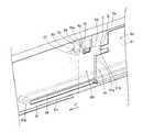
ここで、本実施形態では、第2カセット搬送部8は、染色済みのスライドガラス10が収納されたカセット3を、血液細胞自動分析装置300の導入口300aと、血液塗抹標本作製装置100の保管部9の搬入口9aとの両方に搬送することが可能なように構成されている。図3および図7〜図13を参照して、本実施形態による第2カセット搬送部8の詳細構造について説明する。第2カセット搬送部8は、図7に示すように、フレーム8aに取り付けられた搬送部8bと、カセット検知部8cと、搬送路8dおよび8eとによって構成されている。また、図8、図10および図11に示すように、フレーム8aの搬送部8bに対応する下方の領域には、穴部8fが設けられているとともに、カセット検知部8cに対応する領域には、穴部8gが設けられている。 Here, in this embodiment, the second
また、図7および図9に示すように、搬送部8bは、移動部材81と、移動部材検知センサ82と、プーリ83aおよび83bと、駆動ベルト84と、直動ガイド85と、駆動用モータ86とによって構成されている。そして、図7に示すように、移動部材検知センサ82と、駆動用モータ86とは、フレーム8aの内側に配置されているとともに、プーリ83aおよび83bと、駆動ベルト84と、直動ガイド85とは、フレーム8aの外側に配置されている。 As shown in FIGS. 7 and 9, the
また、図7〜図9に示すように、移動部材81は、板金からなるとともに、2つの当接部81aおよび81bと、検知部81cと、取付部81dとを有する。そして、移動部材81の2つの当接部81aおよび81bと、検知部81cとは、図7および図10に示すように、フレーム8aの内側に配置されているとともに、取付部81dは、図7および図11に示すように、フレーム8aの穴部8fを介してフレーム8aの外側に配置されている。 As shown in FIGS. 7 to 9, the moving
移動部材81の当接部81aおよび81bは、図8に示すように、カセット3の側面部3hおよび3jにそれぞれ当接してカセット3を移動させる機能を有する。また、図9に示すように、移動部材81の検知部81cは、移動部材検知センサ82により移動部材81の位置を検知するために設けられている。移動部材81の取付部81dは、直動ガイド85に取り付けられている。また、移動部材81の取付部81dには、ベルト連結部81eが設けられている。このベルト連結部81eは、取付片81fを用いて、駆動ベルト84に連結されている。また、図7に示すように、駆動ベルト84は、プーリ83aおよび83bに装着されているとともに、プーリ83aは、駆動用モータ86に連結されている。これにより、駆動用モータ86が駆動することによりプーリ83aが回転するとともに、駆動ベルト84が駆動されるので、駆動ベルト84に連結された移動部材81が移動される。なお、駆動ベルト84が装着されたプーリ83aとプーリ83bとの間隔は、駆動ベルト84に連結された移動部材81の当接部81aおよび81bが、血液細胞自動分析装置300の導入口300aに達することが可能なように設定されている。 As shown in FIG. 8, the
また、図11に示すように、カセット検知部8cは、フレーム8aの外側に配置されている。なお、カセット検知部8cが設置される領域は、染色部7(図3参照)から搬送されたカセット3が到達する領域であり、搬送開始位置80となる。また、カセット検知部8cは、カセット検知センサ87と、検知片88と、2つのブラケット89および90とによって構成されている。検知片88は、図12に示すように、板ばね構造を有するとともに、湾曲部88aと検知部88bとを有する。検知片88の湾曲部88aは、凸側がフレーム8aの穴部8gを介してフレーム8aの内側に突出するように配置されている。また、図13に示すように、フレーム8aの内側から検知片88の湾曲部88aに外力が加わった場合には、検知片88の湾曲部88aおよび検知部88bは、フレーム8aの外側方向に移動される。また、図12および図13に示すように、カセット検知センサ87は、検知片88の検知部88bを検出する機能を有する。また、図11に示すように、カセット検知センサ87および検知片88は、それぞれ、ブラケット89および90を介してフレーム8aに取り付けられている。 Moreover, as shown in FIG. 11, the
また、図7に示すように、搬送路8dおよび8eは、板金からなる。そして、搬送路8dの一方の端部は、搬送開始位置80に対応する領域に配置されているとともに、他方の端部は、血液細胞自動分析装置300の導入口300a(図3参照)に隣接する血液塗抹標本作製装置100内の所定領域に配置されている。搬送路8eは、血液細胞自動分析装置300の導入口300aに配置されている。この搬送路8dおよび8eは、移動部材81により押されて移動するカセット3の通路となる。 Further, as shown in FIG. 7, the
また、図3に示した保管部9は、染色部7により染色されたスライドガラス10が収納されたカセット3を保管するために設けられている。なお、保管部9に搬入された染色済みのスライドガラス(標本)10は、目視により分析される。この保管部9には、送り込み部9bと、搬送ベルト9cとが設けられている。 The
本実施形態では、送り込み部9bは、図7に示すように、第2カセット搬送部8のフレーム8aに取り付けられているとともに、保管部9の搬入口9aに対応する領域に配置されている。この送り込み部9bは、第2カセット搬送部8により保管部9の搬入口9aに搬送されたカセット3を、保管部9側に移動させるために設けられている。 In the present embodiment, as shown in FIG. 7, the
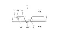
ここで、図3、図16および図17を参照して、本実施形態による保管部9の送り込み部9bの詳細構造について説明する。送り込み部9bは、図16に示すように、板金からなる揺動部材91と、金属製の支持軸92と、板金からなる取付部材93と、プーリ94aおよび94bと、駆動ベルト95と、駆動用モータ96とによって構成されている。揺動部材91は、図17に示すように、カセット3を押圧して保管部9(図3参照)側に移動させるために設けられている。この揺動部材91は、揺動片91aを有するとともに、揺動片91aは、カセット3の上部を押圧するように揺動される。また、揺動部材91には、図16に示すように、揺動部材91が静止位置(非揺動位置)にあることを検出するための検出片91bが一体的に設けられている。なお、フレーム8aには、揺動部材91の検出片91bを検知するための光透過型センサ97がブラケット98を介して取り付けられている。また、図16および図17に示すように、支持軸92は、取付部材93により揺動部材91側に押さえ付けられている。これにより、支持軸92が揺動部材91に対して固定される。また、プーリ94aは、支持軸92の一方端に接続されており、プーリ94bは、駆動用モータ96に接続されている。駆動ベルト95は、プーリ94aおよび94bに装着されている。また、図3に示すように、保管部9には、送り込み部9bにより保管部9側に移動されたカセット3を搬送するための搬送ベルト9cが設けられている。 Here, with reference to FIG. 3, FIG. 16, and FIG. 17, the detailed structure of the
また、本実施形態では、血液塗抹標本作製装置100の制御部110は、染色済みのスライドガラス10が収納されたカセット3を、保管部9の搬入口9aに搬送するか、または、血液細胞自動分析装置300の導入口300aに搬送するかを制御する機能を有する。そして、第2カセット搬送部8および保管部9の送り込み部9bの動作は、制御部110により制御される。また、制御部110には、標本作製条件などの標本情報が記憶されたメモリ111が設けられている。 Moreover, in this embodiment, the
血液細胞自動分析装置300は、図3に示すように、送り込み部301と、カセット収容部302と、スライドガラス取出部303と、バーコード読取部304と、分析部305と、制御部306とを備えている。送り込み部301は、図16に示した血液塗抹標本作製装置100の保管部9の送り込み部9bと同様の構成を有するとともに、血液細胞自動分析装置300の導入口300aに対応する領域に設置されている。また、送り込み部301は、血液細胞自動分析装置300の導入口300aに搬送されたカセット3を、カセット収容部302側に移動させるために設けられている。カセット収容部302は、血液塗抹標本作製装置100の保管部9と同様の構成を有する。このカセット収容部302には、一対の搬送ベルト302aが設けられている。スライドガラス取出部303は、カセット3から染色済みのスライドガラス10を取り出してバーコード読取部304に搬送する機能を有する。バーコード読取部304は、スライドガラス10のフロスト部10aに印字された2次元バーコード10b(図4参照)を読み取る機能を有する。分析部305は、染色済みのスライドガラス10の標本をデジタル画像処理するとともに、血球の分類を自動で行う機能を有する。 As shown in FIG. 3, the blood cell
次に、図1〜図18を参照して、本実施形態による標本作製分析システムの動作について説明する。 Next, with reference to FIGS. 1-18, operation | movement of the sample preparation analysis system by this embodiment is demonstrated.
まず、吸引分注動作として、図1に示すように、起動スイッチ102が押されて血液塗抹標本作製装置100が起動した状態で、血液検体が収容された試験管151が収納された検体ラック150を搬送装置200の搬入部201にセットする。そして、表示操作部101に表示された自動吸引のスタートスイッチを押す。これにより、検体ラック150は、搬送装置200の取り出し部202に搬送される。この後、血液塗抹標本作製装置100のハンド部材160が、検体ラック150の血液が収容された試験管151を把持する。そして、ハンド部材160を上昇させることにより試験管151を持ち上げるとともに、ハンド部材160を回動させることにより試験管151を撹拌した後、図3に示す吸引分注機構部1に試験管151を配置する。そして、ピアサ1aを試験管151のゴム栓151aに突き刺して血液を吸引する。この吸引動作の際には、バルブ1dを開放状態(オン状態)にするとともに、バルブ1eを遮断状態(オフ状態)にする。血液の吸引動作を終了した後、バルブ1dを遮断状態(オフ状態)にするとともに、バルブ1eを開放状態(オン状態)にする。この後、ピペット1bを図3に示した分注・塗抹位置20に移動させる。 First, as a suction dispensing operation, as shown in FIG. 1, in a state where the
次に、吸引分注動作と並行して、図3に示したカセット収容部4によるカセット3の搬入動作が行われる。具体的には、まず、カセット収容部4にカセット3をセットする。これにより、カセット3の搬送ベルト係合部3g(図5および図6参照)がカセット収容部4の送り込みベルト4aに係合された状態でカセット3が搬送されて、カセット待機位置40に送り込まれる。カセット待機位置40のカセット3のうちの先頭のカセット3は、搬送路5cに配置される。 Next, in parallel with the suction dispensing operation, the
次に、図18のフローチャートのステップS1において、血液塗抹標本作製装置100の制御部110は、ホストコンピュータ400(図2参照)から標本情報を取得する。なお、標本情報は、塗抹標本の検体番号および塗抹標本の作製枚数などの情報を含んでいる。また、標本情報は、目視用の標本および自動分析用の標本のうちの一方のみを作製するのか、または、目視用の標本および自動分析用の標本の両方を作製するのかなどの情報も含んでいる。さらに、標本情報は、血液細胞自動分析装置300で分析するかどうかなどの情報も含んでいる。そして、ステップS2において、標本情報に基づいて、制御部110内に蓄積されたデータベースから塗抹条件が呼び出される。なお、塗抹条件は、塗抹標本を作製するための予め設定された条件であり、血液の滴下量、引きガラスの角度および引きガラスの移動速度などが所望の塗抹標本に対応して設定されている。この後、ステップS3において、呼び出された塗抹条件に基づいて、スライドガラス10にピペット1bを用いて血液の滴下(分注)が行われる。この際、自動分析用の標本および目視用の標本の両方を作製する場合には、同一の血液を、2枚のスライドガラス10の各々に分注する。そして、自動分析用の標本を作製する場合には、自動分析用の標本に対応した量の血液が分注されるとともに、目視用の標本を作製する場合には、目視用の標本に対応した量の血液が分注される。 Next, in step S1 of the flowchart of FIG. 18, the
次に、ステップS4において、塗抹条件に基づいて、塗抹部2による塗抹動作が行われる。なお、塗抹部2による塗抹動作は、上記した吸引分注機構部1による吸引分注動作と並行して、または、吸引分注動作の後に行われる。この塗抹部2では、図3に示すように、スライドガラス10を分注・塗抹位置20に供給するとともに、スライドガラス10に滴下された血液を塗抹して乾燥し、かつ、スライドガラス10に印字を行う。具体的には、スライドガラス供給部2aの2つのスライドガラス収納部2bに収納されたスライドガラス10が、図示しない取り出し機構および送りベルト2dにより、送りベルト2e上に供給される。そして、送りベルト2eにより、スライドガラス10が分注・塗抹位置20に搬送される。なお、このスライドガラス10を分注・塗抹位置20に搬送する動作は、上記した吸引分注動作の前に行われている。この状態で、スライドガラス10にピペット1bを用いて血液の滴下(分注)が行われる。 Next, in step S4, a smearing operation by the smearing unit 2 is performed based on the smearing conditions. The smearing operation by the smearing unit 2 is performed in parallel with the suction dispensing operation by the suction dispensing mechanism unit 1 described above or after the suction dispensing operation. As shown in FIG. 3, the smearing unit 2 supplies the
その後、引きガラス2cが、スライドガラス10に当接するように移動されるとともに、スライドガラス10の長手方向に往復移動されることにより、分注・塗抹位置20でスライドガラス10に滴下された血液が塗抹される。この際、自動分析用の標本を作製する場合と、目視用の標本を作製する場合とで、スライドガラス10に対する引きガラス2cの接触角度および引きガラス2cの往復移動の速度が調節される。具体的には、自動分析用の標本の厚みが、目視用の標本の厚みよりも小さくなるように調節される。この後、塗抹されたスライドガラス10は、送りベルト2eにより乾燥位置21aに搬送される。そして、乾燥位置21aにおいて、ファン2fにより、スライドガラス10の塗抹された血液が冷風乾燥される。このスライドガラス10の冷風乾燥は、隣接する2つの乾燥位置21aおよび21bで2回行われる。その後、スライドガラス搬送部2hにより、塗抹済みのスライドガラス10が印字部2gに移動される。そして、印字部2gにおいて、スライドガラス10のフロスト部10aに、検体番号、日付、受付番号、氏名などの標本情報が蓄積された2次元バーコード10bと、日付や氏名の漢字などからなる3行のテキスト10cとが印字される。 Thereafter, the
次に、搬送路5cに配置されたカセット3は、1つずつカセット搬送部5によりスライドガラス挿入部6に搬送される。すなわち、カセット搬送部5を構成するカセット搬送部材5aが、搬送開始位置50からカセット3の側面部3h(図5および図6参照)を押しながら移動することによって、カセット3はスライドガラス挿入部6に搬送される。 Next, the
次に、ステップS5において、塗抹済みのスライドガラス10がカセット3に収納されるとともに、カセット搬送部材5aにより染色部7に搬送され、かつ、染色処理が施される。 Next, in step S5, the smeared
具体的には、カセット回動機構部6aを所定の方向に回動させることにより、カセット3を垂直方向位置から水平方向位置(図3の2点鎖線の位置)に移動させてスライドガラス10を挿入可能な状態にする。この状態で、塗抹部2の縦方向移動片2jを前進移動させることにより、塗抹済みのスライドガラス10をカセット3のスライドガラス収納孔3aに挿入する。これにより、カセット3に、塗抹済みのスライドガラス10が収納される。この後、カセット回動機構部6aを上記所定の方向とは逆方向に回動させることにより、カセット3を元の垂直方向位置に戻す。この後、染色部7において、まず、第1吸引排出部7cにより、カセット3のスライドガラス収納孔3aから塗抹済みのスライドガラス10を持ち上げるとともに、カセット3の染色液吸引分注孔3bにメタノールを分注する。そして、塗抹済みのスライドガラス10をカセット3に戻した後、塗抹済みのスライドガラス10が収納されたカセット3が1つずつ、送り込み部材7aにより搬送ベルト7bに載せられる。そして、搬送ベルト7bにより、カセット3が第2吸引排出部7dに搬送される。 Specifically, by rotating the
第2吸引排出部7dでは、カセット3のスライドガラス収納孔3aから塗抹済みのスライドガラス10を持ち上げるとともに、スライドガラス10の塗抹面にファン7jによる送風を約1秒〜約60秒間当てて塗抹面上の液体成分を蒸発させることによって乾燥させる。なお、第1吸引排出部7cにより塗抹済みのスライドガラス10がメタノールに浸漬されてから第2吸引排出部7dによりスライドガラス10が持ち上げられるまでの時間(浸漬時間)は、約20秒〜約120秒である。 In the second suction / discharge section 7d, the smeared
次に、染色処理(メイグリュンワルド・ギムザ2重染色処理)が施される。まず、第2吸引排出部7dにおいて、カセット3の染色液吸引分注孔3bからメタノールが吸引されて排出された後、カセット3のスライドガラス収納孔3aにスライドガラス10を戻す。次にカセット3の染色液吸引分注孔3bからメイグリュンワルド液(主成分はメタノールで99%)が分注され、塗抹済みのスライドガラス10をメイグリュンワルド液に浸漬する。これにより、メイグリュンワルド・ギムザ2重染色処理が開始される。そして、カセット3が搬送ベルト7bにより搬送されながら、塗抹済みのスライドガラス10は、約1分〜約5分間、染色処理として、メイグリュンワルド液に浸漬される。そして、第3吸引排出部7eにより、カセット3の染色液吸引分注孔3bからメイグリュンワルド液が吸引されて排出された後、カセット3の染色液吸引分注孔3bにメイグリュンワルド希釈液が分注される。そして、カセット3が搬送ベルト7bにより搬送されながら、塗抹済みのスライドガラス10は、約1分〜約5分間、メイグリュンワルド希釈液に浸漬される。そして、第4吸引排出部7fにより、カセット3の染色液吸引分注孔3bからメイグリュンワルド希釈液が吸引されて排出された後、カセット3の染色液吸引分注孔3bにギムザ希釈液が分注される。そして、カセット3が搬送ベルト7bにより搬送されながら、塗抹済みのスライドガラス10は、約1分〜約20分間、ギムザ希釈液に浸漬される。 Next, a dyeing process (Maygrunwald / Giemsa double dyeing process) is performed. First, in the second suction / discharge unit 7 d, methanol is sucked and discharged from the staining liquid suction / dispensing
次に、第5吸引排出部7gにより、カセット3の染色液吸引分注孔3bからギムザ希釈液が吸引されて排出された後、カセット3の染色液吸引分注孔3bに対して洗浄液が分注および吸引されて染色済みのスライドガラス10が水洗される。その後、染色済みのスライドガラス10は、ファン7hにより乾燥される。 Next, after the Giemsa diluted solution is sucked and discharged from the staining liquid suction / dispensing
次に、ステップS6において、第2カセット搬送部8のカセット検知部8cのカセット検知センサ87がオンすることにより、制御部110内に蓄積されたデータベースから標本情報が呼び出される。具体的には、まず、染色済みのスライドガラス10が収納されたカセット3は、塗抹部7から第2カセット搬送部8の搬送開始位置80に搬送される。この際、図13に示すように、カセット検知部8cの検知片88の湾曲部88aが、カセット3によりフレーム8aの外側方向に押圧される。これにより、検知片88の検知部88bが、フレーム8aの外側方向に移動するので、カセット検知センサ87がオンする。その結果、制御部110内のメモリ111に蓄積されたデータベースから標本情報が呼び出される。 Next, in step S <b> 6, when the
次に、ステップS7において、制御部110は、標本情報に基づいて、染色済みのスライドガラス10が収納されたカセット3の搬送先を決定する。すなわち、カセット3を、血液塗抹標本作製装置100の保管部9の搬入口9aまたは血液細胞自動分析装置300の導入口300aのいずれに搬送するかを決定する。 Next, in step S7, the
次に、ステップS8において、制御部110で決定された搬送先情報に基づいて、第2カセット搬送部8により、染色済みのスライドガラス10が収納されたカセット3を決定された搬送先に搬送する。具体的には、図10に示すように、まず、駆動用モータ86を駆動させることにより駆動ベルト84を駆動させることによって、駆動ベルト84に連結された移動部材81を、矢印C方向に移動させる。これにより、移動部材81の当接部81aおよび81bが、それぞれ、カセット3の側面部3hおよび3jに接触する。その結果、カセット3は、移動部材81の当接部81aおよび81bに押されながら矢印C方向に移動する。また、矢印C方向に移動するカセット3は、血液塗抹標本作製装置100内の所定領域に配置された搬送路8dと、血液細胞自動分析装置300の導入口300aに配置された搬送路8eとに沿って移動する。 Next, in step S8, based on the transport destination information determined by the
この際、本実施形態では、制御部110により決定された搬送先情報に基づいて、駆動用モータ86のパルス数が制御される。具体的には、染色済みのスライドガラス10が収納されたカセット3を血液塗抹標本作製装置100の保管部9の搬入口9a(図3参照)に搬送する場合には、図14に示すように、カセット3の矢印C方向の移動が搬入口9aで終了するように、移動部材81の矢印C方向の移動量が調節される。また、染色済みのスライドガラス10が収納されたカセット3を血液細胞自動分析装置300の導入口300a(図3参照)に搬送する場合には、図15に示すように、カセット3の矢印C方向の移動が導入口300aで終了するように、移動部材81の矢印C方向の移動量が調節される。この第2カセット搬送部8によるカセット3の搬送によって、図18に示した動作フローが終了する。 At this time, in the present embodiment, the number of pulses of the
次に、図3に示すように、血液塗抹標本作製装置100の保管部9の搬入口9aに搬送された染色済みのスライドガラス10が収納されたカセット3は、保管部9の送り込み部9bの機能により保管部9側に移動する。具体的には、まず、図17に示すように、駆動用モータ96を回転させることにより駆動ベルト95を駆動させることによって、揺動部材91を駆動用モータ96の回転方向と同じ方向に回動させる。これにより、揺動部材91の揺動片91aがカセット3の上部を押圧する。この揺動片91aのカセット3の上部への押圧動作により、カセット3が保管部9(図3参照)側に移動する。なお、送り込み部9bの動作は、制御部110により制御される。この後、図3に示すように、カセット3は、搬送ベルト9cにより保管部9に搬送されて保管される。 Next, as shown in FIG. 3, the
その一方、血液細胞自動分析装置300の導入口300aに搬送された染色済みのスライドガラス10が収納されたカセット3は、送り込み部301によりカセット収容部302側に押圧されるとともに、搬送ベルト302aによりカセット収容部302に搬送される。この際の血液細胞自動分析装置300の送り込み部301の動作は、保管部9の送り込み部9bの動作と同様である。この後、スライドガラス取出部303において、カセット3から染色済みのスライドガラス10が取り出されるとともに、その染色済みのスライドガラス10がバーコード読取部304に搬送される。次に、バーコード読取部304において、スライドガラス10のフロスト部10aに印字された2次元バーコード10bが読み取られる。そして、バーコード読取部304によって読み取られた染色済みのスライドガラス10の検体番号が制御部306に送られた後、制御部306が検体番号をホストコンピュータ400に問い合わせる。これにより、染色済みのスライドガラス(標本)10の分析が必要であるか否かを分析部305に搬送する前に確認する。最後に、染色済みのスライドガラス(標本)10の分析が必要である場合には、分析部305において、染色済みのスライドガラス(標本)10がデジタル的に画像処理されるとともに、血球の分類が自動的に行われる。この後、血球分類が行われた染色済みのスライドガラス(標本)10は、分析済み標本を収容する収容庫(図示せず)に収容される。また、染色済みのスライドガラス(標本)10の分析が必要でない場合には、分析部305において、染色済みのスライドガラス(標本)10の分析が行われずに、分析標本を収容する収容庫(図示せず)に収容される。なお、スライドガラス取出部303および分析部305の動作は、制御部306により制御される。 On the other hand, the
本実施形態では、上記のように、血液塗抹標本作製装置100に、染色済みのスライドガラス(標本)10が収納されたカセット3を血液細胞自動分析装置300の導入口300aに搬送するための第2カセット搬送部8を設けることによって、その第2カセット搬送部8により、血液塗抹標本作製装置100から血液細胞自動分析装置300への標本の供給動作を自動的に行うことができる。これにより、作業者に負担をかけることなく、血液塗抹標本作製装置100から血液細胞自動分析装置300への標本の供給動作を行うことができる。 In the present embodiment, as described above, the blood
また、本実施形態では、第2カセット搬送部8が、染色済みのスライドガラス10が収納されたカセット3を血液塗抹標本作製装置100の保管部9の搬入口9aに搬送する機能も有するので、血液塗抹標本作製装置100において、血液細胞自動分析装置300に供給する標本と、保管部9に保管する標本との2種類を作製した場合に、染色済みのスライドガラス(標本)10が収納されたカセット3を、1つの第2カセット搬送部8により保管部9の搬入口9aと血液細胞自動分析装置300の導入口300aとに振り分けることができる。 Further, in this embodiment, the second
また、本実施形態では、血液塗抹標本作製装置100に、染色済みのスライドガラス10が収納されたカセット3を、保管部9の搬入口9aまたは血液細胞自動分析装置300の導入口300aに搬送するように第2カセット搬送部8を制御する制御部110を設けることによって、容易に、保管部9の搬入口9aと血液細胞自動分析装置300の導入口300aとに染色済みのスライドガラス10が収納されたカセット3を振り分けることができる。 In this embodiment, the blood smear
また、本実施形態では、血液塗抹標本作製装置100の保管部9に、保管部9の搬入口9aに搬送されたカセット3を保管部9側に移動させる送り込み部9bを設けるとともに、第2カセット搬送部8により染色済みのスライドガラス10が収納されたカセット3が保管部9の搬入口9aに搬送された場合に、カセット3を保管部9側に移動させるように送り込み部9bを制御部110により制御することによって、容易に、保管部9の搬入口9aに搬送された染色済みのスライドガラス10が収納されたカセット3を、保管部9側に移動させることができる。 Further, in the present embodiment, the
また、本実施形態では、第2カセット搬送部8に、カセット3に当接してカセット3を移動させる移動部材81と、移動部材81を駆動する駆動用モータ86とを設けることによって、容易に、第2カセット搬送部8の移動部材81により、血液細胞自動分析装置300の導入口300aにカセット3を搬送することができる。 Further, in the present embodiment, by providing the second
また、本実施形態では、第2カセット搬送部8の移動部材81を、カセット3の側面部3hに当接する当接部81aと、カセット3の側面部3jに当接する当接部81bとを有するように構成することによって、カセット3の側面部3hおよび3jに、それぞれ、移動部材81の当接部81aおよび81bを当接させることができるので、血液細胞自動分析装置300の導入口300aに安定してカセット3を搬送することができる。 Further, in the present embodiment, the moving
また、本実施形態では、血液塗抹標本作製装置100内の所定領域に配置された搬送路8dと、血液細胞自動分析装置300の導入口300aに配置された搬送路8eとを設けることによって、第2カセット搬送部8の搬送開始位置80から血液塗抹標本作製装置100の保管部9の搬入口9aを通過して血液細胞自動分析装置300の導入口300aまで搬送路8dと搬送路8eとに沿ってカセット3を移動させることができるので、容易に、血液塗抹標本作製装置100の保管部9の搬入口9aまたは血液細胞自動分析装置300の導入口300aにカセット3を搬送することができる。 In the present embodiment, the
また、本実施形態では、第2カセット搬送部8の搬送開始位置80に、染色済みのスライドガラス10が収納されたカセット3が到達したことを検知するためのカセット検知部8cを設けることによって、容易に、カセット検知部8cにより第2カセット搬送部8の搬送開始位置80にカセット3が到達したことを検知することができる。 Moreover, in this embodiment, by providing the
また、本実施形態では、2つのスライドガラス10の各々に同一の血液(検体)を分注するとともに、2つのスライドガラス10の各々に分注される同一の血液の分注量を、目視用の標本に対応した量と、血液細胞自動分析装置300で分析する標本に対応した量とに調節する機能を有する吸引分注機構部1を設けることによって、容易に、血液細胞自動分析装置300で分析する標本と、目視用の標本とを同一の血液から作製することができる。 In the present embodiment, the same blood (specimen) is dispensed to each of the two
また、本実施形態では、スライドガラス10のフロスト部10aに標本情報が蓄積された2次元バーコード10bを印字するための印字部2gを血液塗抹標本作製装置100に設けるとともに、2次元バーコード10bを読み取るバーコード読取部304を血液細胞自動分析装置300に設けることによって、2次元バーコード10bは、1次元バーコードよりも多くの情報量を蓄積することができるので、スライドガラス10のフロスト部10aに印字される標本情報量を増大させることができる。この場合、血液細胞自動分析装置300に染色済みのスライドガラス(標本)10が収納されたカセット3が第2カセット搬送部8により自動的に供給されたとしても、標本を分析する前にバーコード読取部304により標本情報を確認すれば、標本の取り違えミスが発生するのを抑制することができる。 In the present embodiment, the blood
また、本実施形態では、スライドガラス10のフロスト部10aに、標本情報が蓄積された2次元バーコード10bを印字することによって、2次元バーコード10bには、1次元バーコードよりも多くの情報を蓄積することができるので、スライドガラス10に多くの詳細な標本情報を保持させることができる。その結果、所定のスライドガラス10に印字された2次元バーコード10bを読み取ることにより、ホストコンピュータ400に所定のスライドガラス(標本)10の標本情報を問い合わせることなく、所定のスライドガラス(標本)10に関する多くの詳細な標本情報を確認することができる。この場合、スライドガラス10のフロスト部10aに、2次元バーコード10bに加えて、標本情報としてのテキストデータ(10c〜10e)も印字することによって、2次元バーコード10bの蓄積可能な情報量が多いことにより2次元バーコード10bの印字領域を小さくすることができるので、その分、テキストデータ(10c〜10e)の印字領域を大きくすることができる。これにより、スライドガラス10に多くの標本情報としてのテキストデータ(10c〜10e)を表示させることができる。このため、たとえば、所定のスライドガラス10に印字された2次元バーコード10bを読み取るのが困難である場合には、視覚的に認識することが可能なテキストデータ(10c〜10e)により、ホストコンピュータ400に所定のスライドガラス(標本)10の標本情報を問い合わせることなく、所定のスライドガラス(標本)10に関する多くの標本情報を確認することができる。 In the present embodiment, the two-
また、本実施形態では、フロスト部10aがスライドガラス10の長手方向の一方の端部側の領域に配置されたスライドガラス10において、2次元バーコード10bが印字されるバーコード印字領域F1およびテキストデータ(10c〜10e)が印字されるテキスト印字領域F2を、スライドガラス10の短手方向に互いに隣接するように配置することによって、バーコード印字領域F1およびテキスト印字領域F2を、スライドガラス10の長手方向に互いに隣接するように配置する場合に比べて、スライドガラス10の長手方向の標本作製領域10fの長さを大きくすることができる。これにより、フロスト部10aがスライドガラス10の長手方向の一方の端部側の領域に配置されたスライドガラス10において、バーコード印字領域F1とテキスト印字領域F2とをフロスト部10aに配置したとしても、スライドガラス10の標本作製領域10fが小さくなることがない。この場合、2次元バーコード10bを、平面的に見て正方形状にすることによって、2次元バーコード10bの配置方向を変化させたとしても、テキスト印字領域F2が変化することはない。 Further, in the present embodiment, the barcode printing area F1 in which the two-
また、本実施形態では、テキストデータ(10c〜10e)を、異なる種類のデータである日付10c、名前10dおよび検体番号10eの3行に分割することによって、日付10c、名前10dおよび検体番号10eの3つを1行にまとめて表示する場合に比べて、テキストデータ(10c〜10e)を読みやすくすることができる。この場合、3行のテキストデータ(10c〜10e)の各々を、スライドガラス10の長手方向に互いに隣接するように配置するとともに、テキストデータ(10c〜10e)の各々を構成する文字および数字を、スライドガラス10の短手方向に沿って配列することによって、テキストデータ(10c〜10e)をより読みやすくすることができる。 In this embodiment, the text data (10c to 10e) is divided into three lines of
また、本実施形態では、3行のテキストデータ(10c〜10e)の各々を、バーコード印字領域F1とテキスト印字領域F2とのスライドガラス10の長手方向の長さが同じになるように配置することによって、スライドガラス10のフロスト部10aにおいて、標本情報が配置されない無駄な領域が増加するのを抑制することができる。 In the present embodiment, each of the three lines of text data (10c to 10e) is arranged such that the length in the longitudinal direction of the
また、本実施形態では、スライドガラス10のフロスト部10aに対応する領域上に、印字可能なコーティング膜10gを形成するとともに、そのフロスト部10aに位置するコーティング膜10gの上面上に、2次元バーコード10bおよび3行のテキストデータ(10c〜10e)を印字することによって、容易に、スライドガラス10のフロスト部10aに標本情報(検体番号、日付、受付番号および氏名)を表示させることができる。この場合、コーティング膜10gを、標本作製領域10fを挟むように、フロスト部10aからスライドガラス10の長手方向に沿って延びるように形成することによって、複数のスライドガラス10を重ねたとしても、スライドガラス10同士が互いに密着するのを抑制することができる。 In the present embodiment, a
なお、今回開示された実施形態は、すべての点で例示であって制限的なものではないと考えられるべきである。本発明の範囲は、上記した実施形態の説明ではなく特許請求の範囲によって示され、さらに特許請求の範囲と均等の意味および範囲内でのすべての変更が含まれる。 The embodiment disclosed this time should be considered as illustrative in all points and not restrictive. The scope of the present invention is shown not by the above description of the embodiments but by the scope of claims for patent, and further includes all modifications within the meaning and scope equivalent to the scope of claims for patent.
たとえば、上記実施形態では、血液塗抹標本作製装置を備えた標本作製分析システムに本発明を適用した例を示したが、本発明はこれに限らず、血液塗抹標本作製装置以外の標本作製装置を備えた標本作製分析システムにも適用可能である。 For example, in the above-described embodiment, an example in which the present invention is applied to a sample preparation / analysis system including a blood smear preparation apparatus has been described. However, the present invention is not limited thereto, and a sample preparation apparatus other than the blood smear preparation apparatus may be used. It is also applicable to the sample preparation analysis system provided.
また、上記実施形態では、血液細胞自動分析装置を備えた標本作製分析システムに本発明を適用したが、本発明はこれに限らず、血液細胞自動分析装置以外の標本分析装置を備えた標本作製分析システムにも適用可能である。 In the above embodiment, the present invention is applied to the sample preparation / analysis system including the blood cell automatic analyzer. However, the present invention is not limited thereto, and the sample preparation includes a sample analyzer other than the blood cell automatic analyzer. It can also be applied to analysis systems.
また、上記実施形態では、血液塗抹標本作製装置に保管部を設けるとともに、血液塗抹標本作製装置で作製した標本を、保管部の搬入口と血液細胞自動分析装置の導入口とに振り分けるようにしたが、本発明はこれに限らず、血液塗抹標本作製装置に保管部を設けずに、血液塗抹標本作製装置で作製した全ての標本を血液細胞自動分析装置の導入口に搬送してもよい。 In the above embodiment, the blood smear sample preparation device is provided with a storage unit, and the sample prepared by the blood smear sample preparation device is distributed to the carry-in port of the storage unit and the introduction port of the blood cell automatic analyzer. However, the present invention is not limited to this, and all specimens prepared by the blood smear preparation apparatus may be transported to the introduction port of the blood cell automatic analyzer without providing a storage unit in the blood smear preparation apparatus.
また、上記実施形態では、染色済みのスライドガラスが収納されたカセットの側面部に当接する当接部を有する移動部材によりカセットを搬送するようにしたが、本発明はこれに限らず、カセットに駆動ベルトを係合させるとともに、その駆動ベルトを駆動させることによって、カセットを搬送するようにしてもよい。 Further, in the above embodiment, the cassette is transported by the moving member having a contact portion that contacts the side surface portion of the cassette in which the stained slide glass is stored. However, the present invention is not limited to this, and the cassette is not limited to this. The cassette may be conveyed by engaging the drive belt and driving the drive belt.
また、上記実施形態では、染色済みのスライドガラスが収納されたカセットを血液細胞自動分析装置の導入口に搬送するようにしたが、本発明はこれに限らず、カセットから染色済みのスライドガラスを取り出した後、染色済みのスライドガラスのみを血液細胞自動分析装置の導入口に搬送するようにしてもよい。この場合、血液塗抹標本作製装置および血液細胞自動分析装置を含む標本作製分析システムを、図19に示す第1変形例のような構成にするのが好ましい。 In the above embodiment, the cassette containing the stained slide glass is transported to the inlet of the blood cell automatic analyzer. However, the present invention is not limited to this, and the stained slide glass is transferred from the cassette. After removal, only the stained slide glass may be conveyed to the inlet of the blood cell automatic analyzer. In this case, the sample preparation / analysis system including the blood smear preparation apparatus and the automatic blood cell analysis apparatus is preferably configured as in the first modification shown in FIG.
具体的には、図19に示した本実施形態の第1変形例による標本作製分析システムは、血液塗抹標本作製装置500と血液細胞自動分析装置600とを備えている。この第1変形例による血液塗抹標本作製装置500は、上記実施形態と同様の吸引分注機構部と、塗抹部と、樹脂製のカセット(図示せず)と、カセット収容部4と、第1カセット搬送部5と、スライドガラス挿入部と、染色部7と、第2カセット搬送部8と、保管部9と、制御部110とを含む。また、制御部110は、ホストコンピュータ400に接続されている。 Specifically, the specimen preparation analysis system according to the first modification of the present embodiment shown in FIG. 19 includes a blood
ここで、本実施形態の第1変形例による標本作製分析システムの血液塗抹標本作製装置500は、スライドガラス取り出し部501と、カセット収容部502と、スライドガラス搬送部503とをさらに含む。スライドガラス取り出し部501は、第2カセット搬送部8により染色部7から搬送されたカセットから染色済みのスライドガラス(図示せず)を取り出すために設けられている。このスライドガラス取り出し部501は、スライドガラスを挟んで引き上げるとともに、スライドガラスをスライドガラス搬送部503に載置するためのチャック機構部(図示せず)を有する。また、カセット収容部502は、染色済みのスライドガラスが取り出された後のカセットを収容するために設けられている。また、スライドガラス搬送部503は、スライドガラス取り出し部501によりカセットから取り出された染色済みのスライドガラスを、血液細胞自動分析装置600の導入口600aに搬送するために設けられている。このスライドガラス搬送部503は、カセット収容部4および保管部9と同様、一対の搬送ベルト(図示せず)を有する。 Here, the blood
また、本実施形態の第1変形例による標本作製分析システムの血液細胞自動分析装置600は、スライドガラス搬送部601と、バーコード読取部602と、分析部603と、制御部604とを含む。スライドガラス搬送部601は、血液塗抹標本作製装置500のスライドガラス搬送部503により導入口600aに搬送された染色済みのスライドガラスを、バーコード読取部602に搬送するために設けられている。また、バーコード読取部602は、スライドガラスに印字された2次元バーコード(図示せず)を読み取るために設けられている。また、分析部603は、染色済みのスライドガラスの標本をデジタル画像処理するとともに、血球の分類を自動で行うために設けられている。また、制御部604は、バーコード読取部602および分析部603の動作を制御するために設けられている。 The automatic
本実施形態の第1変形例による標本作製分析システムでは、上記のように、血液塗抹標本作製装置500に、カセットから取り出された染色済みのスライドガラス(標本)を血液細胞自動分析装置600の導入口600aに搬送するためのスライドガラス搬送部503を設けることによって、そのスライドガラス搬送部503により、血液塗抹標本作製装置500から血液細胞自動分析装置600への標本(スライドガラス)の供給動作を自動的に行うことができる。これにより、作業者に負担をかけることなく、血液塗抹標本作製装置500から血液細胞自動分析装置600への標本(スライドガラス)の供給動作を行うことができる。 In the sample preparation / analysis system according to the first modified example of the present embodiment, as described above, the blood cell
また、本実施形態の第1変形例による標本作製分析システムでは、血液塗抹標本作製装置500に、第2カセット搬送部8により染色部7から搬送されたカセットから染色済みのスライドガラスを取り出すためのスライドガラス取り出し部501を設けることによって、容易に、スライドガラス取り出し部501により染色済みのスライドガラスをカセットから取り出すことができる。これにより、容易に、スライドガラス搬送部503により、カセットから取り出された染色済みのスライドガラスを血液細胞自動分析装置600の導入口600aに搬送することができる。 Further, in the sample preparation / analysis system according to the first modification of the present embodiment, the blood
また、上記実施形態では、染色済みのスライドガラスが収納されたカセットを血液細胞自動分析装置の導入口に搬送するようにしたが、本発明はこれに限らず、染色済みのスライドガラスが収納されたカセットを収容して血液細胞自動分析装置に供給する別ユニットを設け、染色済みのスライドガラスが収納されたカセットを別ユニットの導入口に搬送するようにしてもよい。この場合、血液塗抹標本作製装置および血液細胞自動分析装置を含む標本作製分析システムを、図20に示す第2変形例のような構成にするのが好ましい。 In the above embodiment, the cassette in which the stained slide glass is stored is transported to the introduction port of the automatic blood cell analyzer. However, the present invention is not limited to this, and the stained slide glass is stored. A separate unit that accommodates the cassette and supplies it to the automatic blood cell analyzer may be provided, and the cassette containing the stained slide glass may be conveyed to the inlet of the separate unit. In this case, the sample preparation / analysis system including the blood smear preparation apparatus and the automatic blood cell analysis apparatus is preferably configured as in the second modification shown in FIG.
具体的には、図20に示した本実施形態の第2変形例による標本作製分析システムは、図2に示した血液細胞自動分析装置300のカセット収容部302が、血液細胞自動分析装置300とは別個に設けられたカセット供給ユニット700に含まれている。また、カセット供給ユニット700のカセット収容部302には、染色済みのスライドガラスが収納されたカセットを血液細胞自動分析装置300に供給するための供給部701が設けられている。そして、カセット供給ユニット700のカセット収容部302には、血液塗抹標本作製装置100の染色部7から第2カセット搬送部8により搬送される染色済みのスライドガラスが収納されたカセットが、導入口700aを介して収容される。そして、カセット供給ユニット700のカセット収容部302に収容された染色済みのスライドガラスが収納されたカセットが、供給部701により血液細胞自動分析装置300に供給される。また、カセット供給ユニット700は、カセット保管部307を含んでいる。このカセット供給ユニット700のカセット保管部307は、血液細胞自動分析装置300のスライドガラス取り出し部303においてカセットから染色済みのスライドガラスが取り出された後に、その染色済みのスライドガラスが取り出された後のカセットを保管するために設けられている。なお、本実施形態の第2変形例による標本作製分析システムのその他の構成は、上記実施形態と同様である。 Specifically, in the sample preparation / analysis system according to the second modification of the present embodiment shown in FIG. 20, the
本実施形態の第2変形例による標本作製分析システムでは、上記のように、染色済みのスライドガラスが収納されたカセットを収容して血液細胞自動分析装置300に供給するカセット供給ユニット700を設けることによって、血液塗抹標本作製装置100からカセット供給ユニット700を介して血液細胞自動分析装置300へ染色済みのスライドガラスが収納されたカセットの供給動作を自動的に行うことができる。これにより、作業者に負担をかけることなく、血液塗抹標本作製装置100から血液細胞自動分析装置300への染色済みのスライドガラスが収納されたカセットの供給動作を行うことができる。また、染色済みのスライドガラスが収納されたカセットの血液細胞自動分析装置300への供給を血液細胞自動分析装置300とは別ユニットのカセット供給ユニット700を用いて行うようにしたので、カセット供給ユニット700を取りはずすことにより、容易に血液細胞自動分析装置300を単独で動作させることができる。 In the sample preparation / analysis system according to the second modified example of the present embodiment, as described above, the
また、本実施形態では、スライドガラス10のフロスト部10aに対応する領域上に、印字可能なコーティング膜10gを形成するとともに、そのコーティング膜10gの上面上に、2次元バーコード10bおよび3行のテキストデータ(10c〜10e)を印字したが、本発明はこれに限らず、図21に示す第3変形例のように構成してもよい。具体的には、図21に示すように、スライドガラス10のフロスト部10aに対応する領域上に、コーティング膜を形成せずに、2次元バーコード11aおよび3行のテキストデータ(日付11b、氏名11cおよび検体番号11d)が印字されたラベル11を貼付してもよい。 In the present embodiment, a
また、本実施形態では、スライドガラスのフロスト部に形成されたコーティング膜と同じコーティング膜を、標本作製領域を挟むように、フロスト部からスライドガラスの長手方向に沿って延びるように形成したが、本発明はこれに限らず、フロスト部に形成されたコーティング膜とは異なる材料からなるコーティング膜を、標本作製領域を挟むように、フロスト部からスライドガラスの長手方向に沿って延びるように形成してもよい。 Further, in the present embodiment, the same coating film as the coating film formed on the frost portion of the slide glass is formed so as to extend along the longitudinal direction of the slide glass from the frost portion so as to sandwich the specimen preparation region. The present invention is not limited to this, and a coating film made of a material different from the coating film formed on the frost portion is formed so as to extend from the frost portion along the longitudinal direction of the slide glass so as to sandwich the specimen preparation region. May be.
また、本実施形態では、検体番号、日付、受付番号および氏名などの標本情報を2次元バーコードに蓄積したが、本発明はこれに限らず、血液分析装置で測定した分析結果、WBC(白血球)、RBC(赤血球)、HGB(ヘモグロビン濃度)、HCT(ヘマトクリット)、MCV(平均赤血球容積)、MCH(平均赤血球色素量)、MCHC(平均赤血球色素濃度)、PLT(血小板数)および白血球5分類(好中球、好酸球、好塩基球、単球およびリンパ球)結果などから選択された情報を標本情報として2次元バーコードに蓄積してもよい。本実施形態では、標本情報を2次元バーコードに蓄積するように構成することによって、上記した分析結果などの多くの情報をスライドガラスに保持することができる。そして、上記した分析結果などをスライドガラスに保持した場合には、スライドガラスを保管した後、その保管されたスライドガラスに作製された標本を再分析する際に、2次元バーコードを読み取ることにより、検体番号などの標本情報に加えて、標本に対して行われた分析結果などを認識することが可能となる。これにより、保管されたスライドガラスに作製された標本を再分析する際に、ホストコンピュータに上記した分析結果などを問い合わせる必要がなくなる。 In this embodiment, specimen information such as the specimen number, date, reception number, and name is stored in the two-dimensional barcode. However, the present invention is not limited to this, and the analysis result measured by the blood analyzer, WBC (white blood cell) ), RBC (red blood cells), HGB (hemoglobin concentration), HCT (hematocrit), MCV (average red blood cell volume), MCH (average red blood cell pigment content), MCHC (average red blood cell pigment concentration), PLT (platelet count) and
また、本実施形態では、スライドガラスのフロスト部に表示するテキストデータを、数字または英文字により構成したが、本発明はこれに限らず、数字または英文字以外に、漢字、ひらがなおよびカタカナを用いてもよい。 In this embodiment, the text data to be displayed on the frosted portion of the slide glass is composed of numbers or alphabetic characters, but the present invention is not limited to this, and kanji, hiragana, and katakana are used in addition to numbers or alphabetic characters. May be.
また、本実施形態では、スライドガラス(標本用プレート)上に、血液塗抹標本を作製したが、本発明はこれに限らず、標本用プレート上に、尿中有形成分を観察するための標本や、癌の転移を診断する細胞診のための標本を作製してもよい。この場合には、ガラスや石英などからなる標本用プレートに代えて、アクリル、塩化ビニルおよびポリカーボネートなどの樹脂からなる標本用プレートを用いてもよい。 In this embodiment, a blood smear is prepared on a slide glass (specimen plate). However, the present invention is not limited to this, and a specimen for observing a urine formed component on the sample plate. Alternatively, a specimen for cytodiagnosis for diagnosing cancer metastasis may be prepared. In this case, instead of the sample plate made of glass, quartz, or the like, a sample plate made of a resin such as acrylic, vinyl chloride, or polycarbonate may be used.
1 吸引分注機構部(染色標本作製部)
2 塗抹部(染色標本作製部)
2g 印字部
6 スライドガラス挿入部(染色標本作製部)
7 染色部(染色標本作製部)
8 第2カセット搬送部(搬送部)
9 保管部(第1保管部)
10 スライドガラス
100 血液塗抹標本作製装置(標本作製装置、標本作製手段)
110 制御部
300 血液細胞自動分析装置(外部装置、標本分析手段)
302 カセット収容部(第2保管部)
304、602 バーコード読取部(識別情報検知手段)
305、603 分析部(分析手段)
306、604 制御部(分析制御手段)
400 ホストコンピュータ(コンピュータ)
500 血液塗抹標本作製装置(標本作製装置)
600 血液細胞自動分析装置(外部装置)
700 カセット供給ユニット(外部装置、標本保管供給手段)
701 供給部
1 Suction dispensing mechanism (stained specimen preparation)
2 Smear part (stained specimen preparation part)
7 Staining part (stained specimen preparation part)
8 Second cassette transport section (transport section)
9 storage section(first storage section)
10
110
302 Cassette housing part (second storage part)
304, 602 Bar code reading unit (identification information detecting means)
305, 603 Analysis unit (analysis means)
306, 604 Control unit (analysis control means)
400 Host computer (computer)
500 Blood smear preparation device (specimen preparation device)
600 Blood cell automatic analyzer (external device)
700 cassette supply unit (external device, specimen storage and supply means)
701 Supply unit
Claims (8)
Translated fromJapanese前記スライドガラス上に前記標本を作製して染色する染色標本作製部と、
前記染色標本作製部で作製された前記染色標本スライドガラスを収容する保管部と、
前記保管部または前記外部装置へ前記染色標本スライドガラスを供給するための搬送部と、
前記標本作製装置と通信可能に接続されたコンピュータから標本情報を取得し、前記標本情報が目視用標本の作製指示である場合、前記染色標本スライドガラスを前記保管部へ供給し、前記標本情報が標本分析装置用標本の作製指示である場合、前記染色標本スライドガラスを前記外部装置へ供給するように前記搬送部を制御する制御部とを備えた、標本作製装置。A specimen preparation device capable of preparing and staining a specimen on a slide glass and supplying a stained specimen slide glass on which a stained specimen is prepared to an external device,
A stained specimen preparation section for preparing and staining the specimen on the slide glass;
A storage unit for storing the stained specimen slide glass prepared in the stained specimen preparation unit;
A transport unit for supplying the stained specimen slide glass to the storage unit or the external device;
When specimen information is acquired from a computer communicably connected to the specimen preparation device, and the specimen information is an instruction for preparation of a specimen for visual observation, the stained specimen slide glass is supplied to the storage unit, and the specimen information is A sample preparation device comprising: a control unitthat controls thetransport unit so as to supply the stained sample slide glass to the external device in the case of a sample preparation instruction for a sample analyzer .
前記染色標本スライドガラスを分析する標本分析手段と、
前記標本作製手段で作製された前記染色標本スライドガラスを保管するための第2保管部と、前記染色標本スライドガラスを前記標本分析手段に供給するための供給部とを有する標本保管供給手段と、
前記染色標本スライドガラスを前記第1保管部へ保管するか前記標本保管供給手段へ供給するか決定するための標本情報を有するコンピュータと、を備え、
前記標本作製手段は、前記コンピュータから取得した前記標本情報が目視用標本の作製指示である場合、前記染色標本スライドガラスを前記第1保管部へ保管し、前記標本情報が標本分析手段用標本の作製指示である場合、前記染色標本スライドガラスを前記標本保管供給手段へ供給を行う、標本作製分析システム。A specimen is prepared on a slide glass and stained to prepare astained specimen slide glass, and a specimen preparation meanshaving a first storage unit for storing the stained specimen slide glass ;
Sample analysis means for analyzing the stained specimen slide glass;
A specimen storage and supply means having asecond storage part for storing the stained specimen slide glass prepared by the specimen preparation means, and a supply part for supplying the stained specimen slide glass to the specimen analysis means;
A computer having specimen information for determining whether to store the stained specimen slide glass in the first storage section or to supply to the specimen storage supply means,
The specimen preparation means stores the stained specimen slide glass in the first storage unit when the specimen information acquired from the computer is an instruction for preparation of a visual specimen, and the specimen information is stored in the specimen analysis means specimen. A sample preparation analysis systemthat supplies the stained specimen slide glass to the specimen storage and supply means when it is a preparation instruction .
Priority Applications (1)
| Application Number | Priority Date | Filing Date | Title |
|---|---|---|---|
| JP2005184196AJP4598611B2 (en) | 2004-06-30 | 2005-06-24 | Sample preparation apparatus and sample preparation analysis system |
Applications Claiming Priority (2)
| Application Number | Priority Date | Filing Date | Title |
|---|---|---|---|
| JP2004192880 | 2004-06-30 | ||
| JP2005184196AJP4598611B2 (en) | 2004-06-30 | 2005-06-24 | Sample preparation apparatus and sample preparation analysis system |
Related Child Applications (2)
| Application Number | Title | Priority Date | Filing Date |
|---|---|---|---|
| JP2005184228ADivisionJP4757547B2 (en) | 2004-06-30 | 2005-06-24 | Specimen slide glass |
| JP2010039542ADivisionJP4757945B2 (en) | 2004-06-30 | 2010-02-25 | Sample slide glass production equipment |
Publications (2)
| Publication Number | Publication Date |
|---|---|
| JP2006047289A JP2006047289A (en) | 2006-02-16 |
| JP4598611B2true JP4598611B2 (en) | 2010-12-15 |
Family
ID=36025980
Family Applications (1)
| Application Number | Title | Priority Date | Filing Date |
|---|---|---|---|
| JP2005184196AExpired - Fee RelatedJP4598611B2 (en) | 2004-06-30 | 2005-06-24 | Sample preparation apparatus and sample preparation analysis system |
Country Status (1)
| Country | Link |
|---|---|
| JP (1) | JP4598611B2 (en) |
Families Citing this family (10)
| Publication number | Priority date | Publication date | Assignee | Title |
|---|---|---|---|---|
| CA2643582A1 (en)* | 2006-03-10 | 2007-09-20 | Hadas Lewy | Automated sampling and analysis using a personal sampler device |
| JP5063999B2 (en)* | 2006-11-30 | 2012-10-31 | シスメックス株式会社 | Blood image analyzer |
| JP4975599B2 (en)* | 2007-12-17 | 2012-07-11 | シスメックス株式会社 | Specimen preparation apparatus and specimen preparation method |
| DE102010036317B4 (en)* | 2010-07-09 | 2020-07-30 | Leica Biosystems Nussloch Gmbh | Automatic adjustment of a dyeing device |
| US8388891B2 (en)* | 2010-12-28 | 2013-03-05 | Sakura Finetek U.S.A., Inc. | Automated system and method of processing biological specimens |
| US9384192B2 (en)* | 2012-07-25 | 2016-07-05 | Leica Biosystems Imaging, Inc. | Systems and methods for tracking a slide using a composite barcode label |
| JP2016017823A (en)* | 2014-07-08 | 2016-02-01 | 株式会社日立ハイテクサイエンス | Sample plate for x-ray analysis and fluorescent x-ray analyzer |
| JP6208301B1 (en) | 2016-07-29 | 2017-10-04 | シスメックス株式会社 | Specimen transport device, smear sample system, and smear preparation device |
| EP3800461A1 (en) | 2016-07-29 | 2021-04-07 | Sysmex Corporation | Smear analysis system and method |
| EP3997434A4 (en)* | 2019-07-09 | 2023-07-26 | The Regents of the University of California | AUTOMATED RAPID ON-SITE ASSESSMENT AND COLORING MACHINE |
Family Cites Families (5)
| Publication number | Priority date | Publication date | Assignee | Title |
|---|---|---|---|---|
| JPH04291157A (en)* | 1991-03-20 | 1992-10-15 | Hitachi Ltd | Specimen making apparatus |
| JPH04316169A (en)* | 1991-04-16 | 1992-11-06 | Omron Corp | Blood cell analyzing device |
| JP3976356B2 (en)* | 1995-03-31 | 2007-09-19 | シスメックス株式会社 | Automatic specimen preparation device |
| JPH09218932A (en)* | 1996-02-13 | 1997-08-19 | Olympus Optical Co Ltd | Slide glass information recording medium |
| JP3357600B2 (en)* | 1998-02-18 | 2002-12-16 | シスメックス株式会社 | Smear preparation method and apparatus |
- 2005
- 2005-06-24JPJP2005184196Apatent/JP4598611B2/ennot_activeExpired - Fee Related
Also Published As
| Publication number | Publication date |
|---|---|
| JP2006047289A (en) | 2006-02-16 |
Similar Documents
| Publication | Publication Date | Title |
|---|---|---|
| JP4757945B2 (en) | Sample slide glass production equipment | |
| EP2072993B1 (en) | Smear slide preparing apparatus and smear slide preparing method | |
| JP4508790B2 (en) | Sample preparation equipment | |
| US7790107B2 (en) | Sample image obtaining apparatus, sample image obtaining system, and method for obtaining sample image | |
| JP4567767B2 (en) | Automatic marking method for sample container. | |
| CN102023224B (en) | Recycle collecting unit and sample processing apparatus | |
| AU2024200066B2 (en) | Automated staining system and reaction chamber | |
| JP4598611B2 (en) | Sample preparation apparatus and sample preparation analysis system | |
| JP5372734B2 (en) | Sample processing system and sample transport unit | |
| EP3276328B1 (en) | Smear transporting apparatus, smear image capture system, and smear analysis system | |
| JP6205029B1 (en) | Specimen transport apparatus, specimen image imaging system, and specimen analysis system | |
| JP6208301B1 (en) | Specimen transport device, smear sample system, and smear preparation device | |
| JP7223888B2 (en) | Specimen conveying device and specimen conveying method | |
| CN102023110B (en) | Sample processing device, sample transporting device, and sample rack transporting method | |
| JP4757547B2 (en) | Specimen slide glass | |
| JP4191533B2 (en) | Sample analysis apparatus and method |
Legal Events
| Date | Code | Title | Description |
|---|---|---|---|
| A621 | Written request for application examination | Free format text:JAPANESE INTERMEDIATE CODE: A621 Effective date:20080606 | |
| A977 | Report on retrieval | Free format text:JAPANESE INTERMEDIATE CODE: A971007 Effective date:20100708 | |
| A131 | Notification of reasons for refusal | Free format text:JAPANESE INTERMEDIATE CODE: A131 Effective date:20100713 | |
| A521 | Request for written amendment filed | Free format text:JAPANESE INTERMEDIATE CODE: A523 Effective date:20100830 | |
| TRDD | Decision of grant or rejection written | ||
| A01 | Written decision to grant a patent or to grant a registration (utility model) | Free format text:JAPANESE INTERMEDIATE CODE: A01 Effective date:20100914 | |
| A01 | Written decision to grant a patent or to grant a registration (utility model) | Free format text:JAPANESE INTERMEDIATE CODE: A01 | |
| A61 | First payment of annual fees (during grant procedure) | Free format text:JAPANESE INTERMEDIATE CODE: A61 Effective date:20100924 | |
| R150 | Certificate of patent or registration of utility model | Ref document number:4598611 Country of ref document:JP Free format text:JAPANESE INTERMEDIATE CODE: R150 Free format text:JAPANESE INTERMEDIATE CODE: R150 | |
| FPAY | Renewal fee payment (event date is renewal date of database) | Free format text:PAYMENT UNTIL: 20131001 Year of fee payment:3 | |
| R250 | Receipt of annual fees | Free format text:JAPANESE INTERMEDIATE CODE: R250 | |
| R250 | Receipt of annual fees | Free format text:JAPANESE INTERMEDIATE CODE: R250 | |
| R250 | Receipt of annual fees | Free format text:JAPANESE INTERMEDIATE CODE: R250 | |
| R250 | Receipt of annual fees | Free format text:JAPANESE INTERMEDIATE CODE: R250 | |
| R250 | Receipt of annual fees | Free format text:JAPANESE INTERMEDIATE CODE: R250 | |
| LAPS | Cancellation because of no payment of annual fees |