JP4598529B2 - Reforming and hydrogen purification equipment - Google Patents
Reforming and hydrogen purification equipmentDownload PDFInfo
- Publication number
- JP4598529B2 JP4598529B2JP2004541679AJP2004541679AJP4598529B2JP 4598529 B2JP4598529 B2JP 4598529B2JP 2004541679 AJP2004541679 AJP 2004541679AJP 2004541679 AJP2004541679 AJP 2004541679AJP 4598529 B2JP4598529 B2JP 4598529B2
- Authority
- JP
- Japan
- Prior art keywords
- hydrogen
- heat
- raffinate
- reformer
- pressure vessel
- Prior art date
- Legal status (The legal status is an assumption and is not a legal conclusion. Google has not performed a legal analysis and makes no representation as to the accuracy of the status listed.)
- Expired - Fee Related
Links
- 239000001257hydrogenSubstances0.000titleclaimsdescription132
- 229910052739hydrogenInorganic materials0.000titleclaimsdescription132
- UFHFLCQGNIYNRP-UHFFFAOYSA-NHydrogenChemical compound[H][H]UFHFLCQGNIYNRP-UHFFFAOYSA-N0.000titleclaimsdescription109
- 238000000746purificationMethods0.000titledescription10
- 238000002407reformingMethods0.000titledescription9
- 239000003054catalystSubstances0.000claimsdescription119
- 239000000446fuelSubstances0.000claimsdescription51
- UGFAIRIUMAVXCW-UHFFFAOYSA-NCarbon monoxideChemical compound[O+]#[C-]UGFAIRIUMAVXCW-UHFFFAOYSA-N0.000claimsdescription50
- 239000003546flue gasSubstances0.000claimsdescription45
- 239000007789gasSubstances0.000claimsdescription43
- 238000010438heat treatmentMethods0.000claimsdescription39
- 239000012528membraneSubstances0.000claimsdescription31
- 150000002431hydrogenChemical class0.000claimsdescription25
- 238000012546transferMethods0.000claimsdescription24
- 229910052751metalInorganic materials0.000claimsdescription19
- 239000002184metalSubstances0.000claimsdescription19
- 239000012530fluidSubstances0.000claimsdescription14
- 238000011084recoveryMethods0.000claimsdescription14
- 230000001681protective effectEffects0.000claimsdescription13
- 238000007789sealingMethods0.000claimsdescription11
- 239000000203mixtureSubstances0.000claimsdescription8
- 239000004020conductorSubstances0.000claimsdescription5
- 230000004907fluxEffects0.000claimsdescription4
- 238000002156mixingMethods0.000claimsdescription2
- 238000011144upstream manufacturingMethods0.000claims3
- 238000007599dischargingMethods0.000claims2
- 230000003197catalytic effectEffects0.000description14
- 238000006243chemical reactionMethods0.000description13
- 238000000034methodMethods0.000description11
- 239000000463materialSubstances0.000description10
- XLYOFNOQVPJJNP-UHFFFAOYSA-NwaterSubstancesOXLYOFNOQVPJJNP-UHFFFAOYSA-N0.000description10
- KDLHZDBZIXYQEI-UHFFFAOYSA-NPalladiumChemical compound[Pd]KDLHZDBZIXYQEI-UHFFFAOYSA-N0.000description8
- 230000008878couplingEffects0.000description7
- 238000010168coupling processMethods0.000description7
- 238000005859coupling reactionMethods0.000description7
- 238000009826distributionMethods0.000description7
- 230000008569processEffects0.000description7
- RYGMFSIKBFXOCR-UHFFFAOYSA-NCopperChemical compound[Cu]RYGMFSIKBFXOCR-UHFFFAOYSA-N0.000description5
- 229910002091carbon monoxideInorganic materials0.000description5
- 238000000576coating methodMethods0.000description5
- 238000010276constructionMethods0.000description5
- 238000000926separation methodMethods0.000description5
- 239000011248coating agentSubstances0.000description4
- 229910052802copperInorganic materials0.000description4
- 239000010949copperSubstances0.000description4
- 229910052763palladiumInorganic materials0.000description4
- 238000005219brazingMethods0.000description3
- 238000003466weldingMethods0.000description3
- CURLTUGMZLYLDI-UHFFFAOYSA-NCarbon dioxideChemical compoundO=C=OCURLTUGMZLYLDI-UHFFFAOYSA-N0.000description2
- 229910000881Cu alloyInorganic materials0.000description2
- 229910052782aluminiumInorganic materials0.000description2
- XAGFODPZIPBFFR-UHFFFAOYSA-NaluminiumChemical compound[Al]XAGFODPZIPBFFR-UHFFFAOYSA-N0.000description2
- QVGXLLKOCUKJST-UHFFFAOYSA-Natomic oxygenChemical compound[O]QVGXLLKOCUKJST-UHFFFAOYSA-N0.000description2
- 230000000903blocking effectEffects0.000description2
- 239000006227byproductSubstances0.000description2
- 239000000919ceramicSubstances0.000description2
- 238000013461designMethods0.000description2
- 238000000605extractionMethods0.000description2
- 238000009413insulationMethods0.000description2
- VNWKTOKETHGBQD-UHFFFAOYSA-NmethaneChemical compoundCVNWKTOKETHGBQD-UHFFFAOYSA-N0.000description2
- 238000012544monitoring processMethods0.000description2
- 230000003647oxidationEffects0.000description2
- 238000007254oxidation reactionMethods0.000description2
- 239000001301oxygenSubstances0.000description2
- 229910052760oxygenInorganic materials0.000description2
- 239000011236particulate materialSubstances0.000description2
- 230000000737periodic effectEffects0.000description2
- 230000002093peripheral effectEffects0.000description2
- 238000006057reforming reactionMethods0.000description2
- 238000000629steam reformingMethods0.000description2
- OKTJSMMVPCPJKN-UHFFFAOYSA-NCarbonChemical compound[C]OKTJSMMVPCPJKN-UHFFFAOYSA-N0.000description1
- LFQSCWFLJHTTHZ-UHFFFAOYSA-NEthanolChemical compoundCCOLFQSCWFLJHTTHZ-UHFFFAOYSA-N0.000description1
- 230000032683agingEffects0.000description1
- 150000001298alcoholsChemical class0.000description1
- WYTGDNHDOZPMIW-RCBQFDQVSA-NalstonineNatural productsC1=CC2=C3C=CC=CC3=NC2=C2N1C[C@H]1[C@H](C)OC=C(C(=O)OC)[C@H]1C2WYTGDNHDOZPMIW-RCBQFDQVSA-N0.000description1
- 238000000137annealingMethods0.000description1
- 230000003190augmentative effectEffects0.000description1
- 238000002453autothermal reformingMethods0.000description1
- 230000004323axial lengthEffects0.000description1
- 230000004888barrier functionEffects0.000description1
- 229910052799carbonInorganic materials0.000description1
- 229910002092carbon dioxideInorganic materials0.000description1
- 239000001569carbon dioxideSubstances0.000description1
- 229910010293ceramic materialInorganic materials0.000description1
- 238000001311chemical methods and processMethods0.000description1
- 238000002485combustion reactionMethods0.000description1
- 150000001875compoundsChemical class0.000description1
- 230000007423decreaseEffects0.000description1
- 230000001419dependent effectEffects0.000description1
- 238000006477desulfuration reactionMethods0.000description1
- 230000023556desulfurizationEffects0.000description1
- 238000010586diagramMethods0.000description1
- 229910003460diamondInorganic materials0.000description1
- 239000010432diamondSubstances0.000description1
- 230000009977dual effectEffects0.000description1
- 230000000694effectsEffects0.000description1
- 230000005611electricityEffects0.000description1
- 238000005516engineering processMethods0.000description1
- 239000004744fabricSubstances0.000description1
- 239000008187granular materialSubstances0.000description1
- 239000010763heavy fuel oilSubstances0.000description1
- 238000011065in-situ storageMethods0.000description1
- 239000011810insulating materialSubstances0.000description1
- 238000002955isolationMethods0.000description1
- 238000011068loading methodMethods0.000description1
- 238000004519manufacturing processMethods0.000description1
- 230000007246mechanismEffects0.000description1
- 229910001092metal group alloyInorganic materials0.000description1
- 238000005272metallurgyMethods0.000description1
- 230000004048modificationEffects0.000description1
- 238000012986modificationMethods0.000description1
- 238000012806monitoring deviceMethods0.000description1
- 238000013021overheatingMethods0.000description1
- 239000005022packaging materialSubstances0.000description1
- 238000007747platingMethods0.000description1
- 231100000572poisoningToxicity0.000description1
- 230000000607poisoning effectEffects0.000description1
- 239000011148porous materialSubstances0.000description1
- 238000002360preparation methodMethods0.000description1
- 238000012545processingMethods0.000description1
- 239000011241protective layerSubstances0.000description1
- 239000004065semiconductorSubstances0.000description1
- 239000000779smokeSubstances0.000description1
- 239000000126substanceSubstances0.000description1
- 230000003685thermal hair damageEffects0.000description1
- 239000008207working materialSubstances0.000description1
Images


Classifications
- C—CHEMISTRY; METALLURGY
- C01—INORGANIC CHEMISTRY
- C01B—NON-METALLIC ELEMENTS; COMPOUNDS THEREOF; METALLOIDS OR COMPOUNDS THEREOF NOT COVERED BY SUBCLASS C01C
- C01B3/00—Hydrogen; Gaseous mixtures containing hydrogen; Separation of hydrogen from mixtures containing it; Purification of hydrogen
- C01B3/50—Separation of hydrogen or hydrogen containing gases from gaseous mixtures, e.g. purification
- C01B3/501—Separation of hydrogen or hydrogen containing gases from gaseous mixtures, e.g. purification by diffusion
- C—CHEMISTRY; METALLURGY
- C01—INORGANIC CHEMISTRY
- C01B—NON-METALLIC ELEMENTS; COMPOUNDS THEREOF; METALLOIDS OR COMPOUNDS THEREOF NOT COVERED BY SUBCLASS C01C
- C01B3/00—Hydrogen; Gaseous mixtures containing hydrogen; Separation of hydrogen from mixtures containing it; Purification of hydrogen
- C01B3/02—Production of hydrogen or of gaseous mixtures containing a substantial proportion of hydrogen
- C01B3/32—Production of hydrogen or of gaseous mixtures containing a substantial proportion of hydrogen by reaction of gaseous or liquid organic compounds with gasifying agents, e.g. water, carbon dioxide, air
- C01B3/34—Production of hydrogen or of gaseous mixtures containing a substantial proportion of hydrogen by reaction of gaseous or liquid organic compounds with gasifying agents, e.g. water, carbon dioxide, air by reaction of hydrocarbons with gasifying agents
- C01B3/38—Production of hydrogen or of gaseous mixtures containing a substantial proportion of hydrogen by reaction of gaseous or liquid organic compounds with gasifying agents, e.g. water, carbon dioxide, air by reaction of hydrocarbons with gasifying agents using catalysts
- C01B3/384—Production of hydrogen or of gaseous mixtures containing a substantial proportion of hydrogen by reaction of gaseous or liquid organic compounds with gasifying agents, e.g. water, carbon dioxide, air by reaction of hydrocarbons with gasifying agents using catalysts the catalyst being continuously externally heated
- C—CHEMISTRY; METALLURGY
- C01—INORGANIC CHEMISTRY
- C01B—NON-METALLIC ELEMENTS; COMPOUNDS THEREOF; METALLOIDS OR COMPOUNDS THEREOF NOT COVERED BY SUBCLASS C01C
- C01B2203/00—Integrated processes for the production of hydrogen or synthesis gas
- C01B2203/02—Processes for making hydrogen or synthesis gas
- C01B2203/0205—Processes for making hydrogen or synthesis gas containing a reforming step
- C01B2203/0227—Processes for making hydrogen or synthesis gas containing a reforming step containing a catalytic reforming step
- C01B2203/0233—Processes for making hydrogen or synthesis gas containing a reforming step containing a catalytic reforming step the reforming step being a steam reforming step
- C—CHEMISTRY; METALLURGY
- C01—INORGANIC CHEMISTRY
- C01B—NON-METALLIC ELEMENTS; COMPOUNDS THEREOF; METALLOIDS OR COMPOUNDS THEREOF NOT COVERED BY SUBCLASS C01C
- C01B2203/00—Integrated processes for the production of hydrogen or synthesis gas
- C01B2203/04—Integrated processes for the production of hydrogen or synthesis gas containing a purification step for the hydrogen or the synthesis gas
- C01B2203/0405—Purification by membrane separation
- C01B2203/041—In-situ membrane purification during hydrogen production
- C—CHEMISTRY; METALLURGY
- C01—INORGANIC CHEMISTRY
- C01B—NON-METALLIC ELEMENTS; COMPOUNDS THEREOF; METALLOIDS OR COMPOUNDS THEREOF NOT COVERED BY SUBCLASS C01C
- C01B2203/00—Integrated processes for the production of hydrogen or synthesis gas
- C01B2203/08—Methods of heating or cooling
- C01B2203/0805—Methods of heating the process for making hydrogen or synthesis gas
- C01B2203/0811—Methods of heating the process for making hydrogen or synthesis gas by combustion of fuel
- Y—GENERAL TAGGING OF NEW TECHNOLOGICAL DEVELOPMENTS; GENERAL TAGGING OF CROSS-SECTIONAL TECHNOLOGIES SPANNING OVER SEVERAL SECTIONS OF THE IPC; TECHNICAL SUBJECTS COVERED BY FORMER USPC CROSS-REFERENCE ART COLLECTIONS [XRACs] AND DIGESTS
- Y02—TECHNOLOGIES OR APPLICATIONS FOR MITIGATION OR ADAPTATION AGAINST CLIMATE CHANGE
- Y02E—REDUCTION OF GREENHOUSE GAS [GHG] EMISSIONS, RELATED TO ENERGY GENERATION, TRANSMISSION OR DISTRIBUTION
- Y02E60/00—Enabling technologies; Technologies with a potential or indirect contribution to GHG emissions mitigation
- Y02E60/30—Hydrogen technology
- Y02E60/50—Fuel cells
- Y—GENERAL TAGGING OF NEW TECHNOLOGICAL DEVELOPMENTS; GENERAL TAGGING OF CROSS-SECTIONAL TECHNOLOGIES SPANNING OVER SEVERAL SECTIONS OF THE IPC; TECHNICAL SUBJECTS COVERED BY FORMER USPC CROSS-REFERENCE ART COLLECTIONS [XRACs] AND DIGESTS
- Y02—TECHNOLOGIES OR APPLICATIONS FOR MITIGATION OR ADAPTATION AGAINST CLIMATE CHANGE
- Y02P—CLIMATE CHANGE MITIGATION TECHNOLOGIES IN THE PRODUCTION OR PROCESSING OF GOODS
- Y02P20/00—Technologies relating to chemical industry
- Y02P20/10—Process efficiency
- Y02P20/129—Energy recovery, e.g. by cogeneration, H2recovery or pressure recovery turbines
Landscapes
- Chemical & Material Sciences (AREA)
- Organic Chemistry (AREA)
- Chemical Kinetics & Catalysis (AREA)
- Engineering & Computer Science (AREA)
- Combustion & Propulsion (AREA)
- Inorganic Chemistry (AREA)
- Health & Medical Sciences (AREA)
- General Health & Medical Sciences (AREA)
- Hydrogen, Water And Hydrids (AREA)
- Fuel Cell (AREA)
- Devices And Processes Conducted In The Presence Of Fluids And Solid Particles (AREA)
Description
Translated fromJapanese本発明は、燃料電池用の精製水素を含む精製水素を製造するための水蒸気改質器に関する。 The present invention relates to a steam reformer for producing purified hydrogen containing purified hydrogen for fuel cells.
精製水素は、半導体、冶金及び化学プロセスにおいて重要な必需品である。精製水素は、水素から電力を製造することができる燃料電池のための燃料源としても極めて有用である。精製水素を製造するための種々の手段が存在する。水素は、触媒床上で高温蒸気によって改質することによってアルコールのような水素含有化合物から遊離させることができる。この反応は吸熱性であるので、熱は外部の燃焼器から供給することができ又はいくらかの酸素を混合し且つ燃料のいくらかを部分的に燃焼することによって現場で供給することができる。前者の方法は、一般的には蒸気改質と称され、熱を供給するために空気又は酸素が燃料と混合されるとき、このプロセスは、自熱改質又は部分酸化改質と称される。改質プロセスが完了すると、実質的なパーセンテージの一酸化炭素が水性ガス移動触媒床で更に反応して水素及び二酸化炭素を形成する。これは、改質されたガス内の一酸化炭素のパーセンテージを下げる。 Purified hydrogen is an important necessity in semiconductor, metallurgy and chemical processes. Purified hydrogen is also very useful as a fuel source for fuel cells that can produce electricity from hydrogen. There are various means for producing purified hydrogen. Hydrogen can be liberated from hydrogen-containing compounds such as alcohols by reforming with hot steam over the catalyst bed. Since this reaction is endothermic, heat can be supplied from an external combustor or can be supplied in situ by mixing some oxygen and partially burning some of the fuel. The former method is commonly referred to as steam reforming, and when air or oxygen is mixed with fuel to provide heat, this process is referred to as autothermal reforming or partial oxidation reforming. . When the reforming process is complete, a substantial percentage of carbon monoxide further reacts in the water gas transfer catalyst bed to form hydrogen and carbon dioxide. This lowers the percentage of carbon monoxide in the reformed gas.
改質されたガス混合物から精製度の高い水素を生成するために、例えば、選択性の膜を介して水素を分離する手段を採用することができる。精製度の高い水素は、次いで工業的プロセス、電力を発生するための燃料電池内又は精製された水素を必要とするその他の用途において使用することができる。いくつかの場合には、水素の精製は使用されず、改質されたガスは、一酸化炭素のレベルを更に下げるために選択的な酸化ステップの後に燃料電池に送られる。後者の場合には、改質器は、一般的に、露点制御、高い一酸化炭素レベルを防止するための注意深い配慮及び水素の多くが排出された後に消費されたガスを受け入れるための燃料電池を備えた統合手段を必要とするであろう。 In order to produce highly purified hydrogen from the reformed gas mixture, for example, a means for separating hydrogen through a selective membrane can be employed. The highly purified hydrogen can then be used in industrial processes, in fuel cells to generate power, or other applications that require purified hydrogen. In some cases, hydrogen purification is not used and the reformed gas is sent to the fuel cell after a selective oxidation step to further reduce the level of carbon monoxide. In the latter case, the reformer generally has a dew point control, careful consideration to prevent high carbon monoxide levels and a fuel cell to accept the gas consumed after much of the hydrogen has been exhausted. You will need an integrated means of preparation.
1999年1月19日に発行されたSteam Reformer With Internal Hydrogen Purification(内部水素精製装置を備えた蒸気改質器)という名称の米国特許第5,861,137号に記載されているような水素の精製技術はよく知られている。上記の特許は、水素精製装置を開示しており且つ従来技術と従来技術状態とを説明している。コスト効率を必要とする実際的な改質器の必要性は明らかである。この特許は、水素を含んでいる燃料の適当な燃料供給原料から精製された水素の一部分を部分的に抽出し且つ燃焼器を作動させるための燃料として多量の水素を有する排出されたラフィネートを使用する方法及び装置を開示している。 Of hydrogen, as described in US Pat. No. 5,861,137, issued January 19, 1999, entitled Steam Reformer With Internal Hydrogen Purification (steam reformer with internal hydrogen purifier). Purification techniques are well known. The above patent discloses a hydrogen purifier and describes the prior art and state of the art. The need for a practical reformer requiring cost efficiency is clear. This patent uses an exhausted raffinate with a large amount of hydrogen as a fuel to partially extract a portion of the purified hydrogen from a suitable fuel feedstock of fuel containing hydrogen and to operate the combustor. A method and apparatus is disclosed.
蒸気改質に基づいた装置を含んでいる水素精製の種々の装置及び特徴を記載している多くの特許に加えて、実質的な量の他の出版物が入手可能である。それにも拘わらず、初期及びその作動期間中の両方において費用効率が高いばかりでなく有効で且つコスト効率の高い提供に容易に適合する改良された水素精製装置の継続的な需要が存在する。燃焼器空気装置内に低い圧力低下を有する改質器の特別な需要がある。 In addition to a number of patents describing various equipment and features of hydrogen purification including equipment based on steam reforming, a substantial amount of other publications are available. Nevertheless, there is a continuing need for improved hydrogen purifiers that are both cost effective as well as effective and cost effective, both early and during their operation. There is a special need for a reformer with a low pressure drop in the combustor air unit.
本発明は、特に、燃焼器による改質器の効率の良い加熱を有するコンパクトなユニットとして構成することができる水素精製改質器に関する。燃焼器のガスは、水素リッチ燃料の処理のための低電力で低コストの空気供給装置をもたらす装置において最小の圧力低下を有する。 The present invention particularly relates to a hydrogen purification reformer that can be configured as a compact unit having efficient heating of the reformer by a combustor. The combustor gas has minimal pressure drop in an apparatus that provides a low power, low cost air supply for the treatment of hydrogen rich fuel.
本発明の新規な改質器装置は、供給原料入口と隔置された供給原料出口との間の供給原料の経路に沿って構成され且つ配置されている触媒ユニット又は床を含んでいる。触媒は、加熱すると供給原料に対して吸熱反応を行って水素を生成する。触媒は、自立素材、粒状素材又はこれらの組み合わせのようなあらゆる入手可能な形態の作動材料によって構成することができる。粒状素材が使用される場合には、閉じ込め包囲体が、水素透過膜を介して後続の収集のために水素の解放を可能にする構造を有する素材を支持している。 The novel reformer apparatus of the present invention includes a catalyst unit or bed constructed and arranged along the feed path between the feed inlet and the spaced feed outlet. When heated, the catalyst performs an endothermic reaction on the feedstock to produce hydrogen. The catalyst can be composed of any available form of working material, such as a self-supporting material, a granular material, or a combination thereof. When particulate material is used, the containment enclosure supports the material with a structure that allows the release of hydrogen for subsequent collection through a hydrogen permeable membrane.
本発明の特別な特徴に従って、燃焼器ユニットは、本質的に燃焼器ユニットから触媒ユニットへ直接流れ且つ実質的に触媒ユニットの全長長さ程度の、すなわち、典型的には触媒ユニットの出口と入口との間の間隔の長さを有する煙道ガス出力の流れを有している。従って、煙道ガスの流れは、触媒のほぼ全長に亘って横切るように通過して流れの中に最小空気圧をもたらす。 In accordance with a particular feature of the present invention, the combustor unit flows essentially directly from the combustor unit to the catalyst unit and is substantially as long as the full length of the catalyst unit, i.e. typically the outlet and inlet of the catalyst unit. A flow of flue gas power having a length of between. Thus, the flue gas flow passes across almost the entire length of the catalyst, resulting in minimal air pressure in the flow.
精製された水素を集めるために水素収集器が触媒ユニットに隣接して配置され、又は代替的には、同じか又は別個の圧力容器内の下流に配置されても良い。現在の実施に従って、水素収集器は、水素を集めるために触媒床から遊離された水素の経路に沿って配置された1以上の水素選択性透過膜を含んでいても良い。 A hydrogen collector may be placed adjacent to the catalyst unit to collect purified hydrogen, or alternatively, downstream in the same or a separate pressure vessel. In accordance with current practice, the hydrogen collector may include one or more hydrogen selective permeable membranes disposed along the path of hydrogen released from the catalyst bed to collect hydrogen.
好ましい構成はまた、特に、触媒の効率の良い機能並びに触媒、供給原料及び供給空気の加熱だけでなく高エネルギ効率を生じる比較的低圧の供給空気の使用可能性を提供する。 The preferred configuration also provides, among other things, the efficient function of the catalyst and the availability of relatively low pressure feed air that results in high energy efficiency as well as heating of the catalyst, feed and feed air.
このようにして、この構成は、遊離水素を製造するための触媒の改良された加熱及び触媒ユニットからの遊離水素の抽出を達成する。この装置は更に、以下に説明するように、供給原料の内部処理のために触媒床の全長に亘って流れの加熱パターンを理想化することを更に可能にする。 In this way, this configuration achieves improved heating of the catalyst to produce free hydrogen and extraction of free hydrogen from the catalyst unit. This apparatus further makes it possible to idealize the heating pattern of the flow over the entire length of the catalyst bed for internal processing of the feed, as will be explained below.
好ましい構成においては、圧力容器は、触媒床又はユニットによって包囲されている閉塞された水素選択性透過膜コアユニットを含んでいる。ガス燃焼加熱ユニットは、圧力容器及び特に触媒床と整合された遊離ガス出力を有している。加熱ユニットは、触媒ユニットの長さ及び断面積に関連する遊離ガスの流れを形成する。遊離ガスの流れは、触媒ユニットの全長に亘って触媒ユニットを加熱するために触媒ユニットの上を横切って通過する。触媒ユニットは、均一に加熱されても良いし又は所望の熱勾配まて加熱されても良い。 In a preferred configuration, the pressure vessel includes a closed hydrogen selective permeable membrane core unit surrounded by a catalyst bed or unit. The gas combustion heating unit has a free gas output aligned with the pressure vessel and in particular with the catalyst bed. The heating unit creates a flow of free gas that is related to the length and cross-sectional area of the catalyst unit. A stream of free gas passes across the catalyst unit to heat the catalyst unit over the entire length of the catalyst unit. The catalyst unit may be heated uniformly or to a desired thermal gradient.
加熱された触媒ユニットを通過する水素リッチ供給原料は改質されて水素を製造する。この水素の実質的な部分は、続いて、水素選択性透過膜のコアユニットを通過し、以下においてラフィネートと称される残りの水素及びその他のガスが圧力容器を出て行き、背圧レギュレータのような圧力制御装置を通過し、続いて、ガス燃焼された加熱ユニットを介して改質プロセスのための熱を供給するために使用される。 The hydrogen rich feedstock that passes through the heated catalyst unit is reformed to produce hydrogen. A substantial portion of this hydrogen then passes through the core unit of the hydrogen-selective permeable membrane, and the remaining hydrogen and other gases, referred to below as raffinates, exit the pressure vessel and Is used to supply heat for the reforming process through a gas-fired heating unit.
加熱ユニットは、圧力容器を出て行くラフィネートによって燃料供給されるのが好ましい触媒燃焼器であるのが好ましい。燃焼器は、別個の燃焼器であっても良いし又は圧力容器の一体部品として構成されても良い。いずれの構成においても、ラフィネートは、空気と混合され、燃焼器内を移動し、圧力容器の上方の燃焼器からの直接加熱された煙道ガスの流れを通過する。 The heating unit is preferably a catalytic combustor, preferably fueled by raffinate exiting the pressure vessel. The combustor may be a separate combustor or may be configured as an integral part of the pressure vessel. In either configuration, the raffinate is mixed with air, travels through the combustor, and passes through a directly heated flue gas stream from the combustor above the pressure vessel.
いずれの構成においても、圧力容器は、熱伝導性材料によって作られている外側外被又は壁を含んでいる。多数の熱伝導フィンは、圧力容器内に含まれている改質触媒床を完全に加熱するために加熱された燃焼器の煙道ガスが通過する容器を通して外側壁に密着されて取り付けられている。圧力容器は、入力燃焼器煙道ガス通路と外側の燃焼器煙道ガス通路との間に配置されている。 In either configuration, the pressure vessel includes an outer envelope or wall made of a thermally conductive material. A number of heat conducting fins are mounted in close contact with the outer wall through the vessel through which the heated combustor flue gas passes to fully heat the reforming catalyst bed contained within the pressure vessel. . The pressure vessel is disposed between the input combustor flue gas passage and the outer combustor flue gas passage.
好ましい構成においては、供給原料は、精製された水素、ラフィネート及び燃焼器煙道ガスのうちの少なくとも1つ、好ましくはこれらの発生源全てからの熱の回収によって予め加熱される。供給原料が所望の反応熱まで十分に予加熱される場合でさえ、触媒内の吸熱反応は、所望の改質反応が起こる十分な温度を維持するために、燃焼器煙道ガスからのような熱の付加的な供給を一般的に必要とする。 In a preferred configuration, the feed is preheated by recovery of heat from at least one of purified hydrogen, raffinate and combustor flue gas, preferably all of these sources. Even when the feedstock is sufficiently preheated to the desired heat of reaction, the endothermic reaction within the catalyst is such as from combustor flue gas to maintain a sufficient temperature at which the desired reforming reaction occurs. An additional supply of heat is generally required.
圧力容器はまた、1以上の収集容器を含む水素収集装置によって形成されることも好ましい。各収集構造は、水素選択性コア膜ユニットを形成しているコアに付着された金属製の水素選択性透過膜を備えた多孔質材料の内側膜コアを含んでいる。金属製の水素選択性膜は、例えば、パラジウム又はパラジウム銅合金からなるコーティングであっても良く、後者は、当業者に良く知られたメッキ及びアニーリング法によって製造しても良い。更に、各コア膜ユニットは、特に、触媒材料との薄い膜の摩滅性の接触を防止するために、分離され且つ触媒ユニットから隔てられている。この目的のために、特に粒状触媒が使用される場合には、触媒と膜との間に保護層が配置されても良く、該保護層は、改質されたガスを水素選択性透過膜へと流通させるための多孔質であるか又は穴を含んでいる。 The pressure vessel is also preferably formed by a hydrogen collection device comprising one or more collection vessels. Each collection structure includes an inner membrane core of porous material with a metal hydrogen-selective permeable membrane attached to the core forming the hydrogen-selective core membrane unit. The metal hydrogen-selective membrane may be a coating made of, for example, palladium or a palladium copper alloy, and the latter may be produced by plating and annealing methods well known to those skilled in the art. Furthermore, each core membrane unit is separated and separated from the catalyst unit, in particular in order to prevent thin membrane abrasive contact with the catalyst material. For this purpose, in particular when a particulate catalyst is used, a protective layer may be arranged between the catalyst and the membrane, which protects the reformed gas into a hydrogen selective permeable membrane. Are porous or contain holes.
好ましい実施形態においては、圧力容器には更に、外側の閉じられた端部と解放可能なカバー又はヘッダーユニットによって閉塞することができる反対側の開口端部とが形成されている。入力及び出力ラインがカバーに固定されている。これらのラインは、供給原料を触媒床に入力する供給原料ラインと、触媒ユニットからラフィネートを受け取るためのラフィネート出力ラインと、コア膜ユニットからの精製された水素を運ぶための精製水素出力ラインとを含んでいる。 In a preferred embodiment, the pressure vessel is further formed with an outer closed end and an opposite open end that can be closed by a releasable cover or header unit. Input and output lines are fixed to the cover. These lines include a feed line that feeds feed into the catalyst bed, a raffinate output line for receiving raffinate from the catalyst unit, and a purified hydrogen output line for carrying purified hydrogen from the core membrane unit. Contains.
圧力容器は、典型的には、金属合金によって作られる。熱の良好な伝導体である複数の隔置されたフィンが圧力容器にしっかりと固定されて該圧力容器から延びている。しかしながら、有利な表面積対体積を有する比較的小さい実施形態においては、フィンは、触媒領域内への熱の移動のためには不要であるかも知れず、従って、圧力容器のフィンは、好ましい実施形態から排除されていて容器が依然として空気と熱との通路及びその出口又は排出通路を形成するようにしても良い。 The pressure vessel is typically made of a metal alloy. A plurality of spaced fins, which are good conductors of heat, are secured to and extend from the pressure vessel. However, in relatively small embodiments having an advantageous surface area to volume, fins may not be necessary for heat transfer into the catalyst zone, and therefore pressure vessel fins are preferred embodiments. The container may still form an air and heat passage and its outlet or discharge passage.
加熱装置は、供給原料の理想的な改質を形成するために触媒ユニット上に流体又は煙道ガスの流れの制御された分布を含んでいるのが好ましい。これは、ユニットの長さに亘って出口まで段階的なパターン又は勾配を有する最大熱入力をユニット内への供給原料入口に必要とする。なぜならば、比較的高い割合の吸熱反応は、触媒内への入口箇所(入口端部)の最も近くで起こるからである。 The heating device preferably includes a controlled distribution of fluid or flue gas flow over the catalyst unit to form an ideal reforming of the feedstock. This requires maximum heat input at the feed inlet into the unit with a stepped pattern or gradient over the length of the unit to the outlet. This is because a relatively high percentage of endothermic reaction takes place closest to the entry point (inlet end) into the catalyst.
本発明の更に別の特徴に従って、全てが高いレベルの熱を含んでいる燃焼器の煙道ガス、加熱されたラフィネート及び集められた水素が、燃焼器への冷たい入力空気を加熱し且つ改質触媒ユニット内の供給原料の通過に先立って水素リッチ供給原料を予め加熱するために使用される。 In accordance with yet another aspect of the present invention, combustor flue gas, heated raffinate and collected hydrogen, all containing high levels of heat, heat and reform the cold input air to the combustor. Used to preheat the hydrogen rich feed prior to passage of the feed in the catalyst unit.
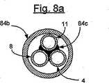
好ましい構造においては、別個の導管は、圧力容器から出て行くときにラフィネート及び精製された水素を運ぶ。各導管は、少なくとも部分的に金属かその他の熱伝導性材料を含んでおり、これらの部分は、相互に結合され且つ向流形態で触媒ユニットへ供給原料を運ぶ対応する第3の金属導管に結合されるか接合されるのが好ましい。冷たい供給原料の加熱を促進するために、いくつかの導管は、例えば溶着、鑞付け等によるような高熱伝導接合によって相互に結合されるのが好ましい。導管を結合する他の形態を使用しても良い。 In a preferred construction, a separate conduit carries raffinate and purified hydrogen as it exits the pressure vessel. Each conduit includes at least a portion of a metal or other thermally conductive material that is coupled to each other and to a corresponding third metal conduit that carries the feedstock to the catalyst unit in countercurrent form. Preferably they are joined or joined. In order to facilitate heating of the cold feedstock, the several conduits are preferably joined together by a high thermal conductivity joint, such as by welding, brazing, and the like. Other forms of coupling the conduit may be used.
更に、一つの好ましい構造においては、触媒床の下流の触媒燃焼器ユニットからの煙道ガスは、例えば燃焼器ユニットの煙道ガスは、例えば燃焼器ユニットの巻き付けられた長さを熱い排出煙道ガスを運ぶ出口通路内に配置することによって入力供給原料ラインの伸長長さに結合されている。この構造は、煙道ガス排出物によって供給原料を予め加熱するために使用することができ、これは触媒燃焼器を使用する場合に特に有利である。 Furthermore, in one preferred construction, the flue gas from the catalytic combustor unit downstream of the catalyst bed, for example, the flue gas of the combustor unit, for example, the hot exhaust flue over the wrapped length of the combustor unit. Coupled to the extended length of the input feed line by placing it in the outlet passage carrying the gas. This structure can be used to preheat the feedstock with flue gas emissions, which is particularly advantageous when using a catalytic combustor.
更に別の好ましい構造に従って、燃焼器に空気を供給するための燃焼器空気入口チャンバと、触媒ユニットから煙道ガスを排出するための排出チャンバとが、側部同士が近接して互いに隔てられた状態で配置されている。伝熱式熱交換器がこれらの2つのチャンバ間に延びていて燃焼器の煙道ガス内の熱を捕獲し且つ煙道ガスを装置から排出する前に好ましくは向流状態で燃焼器入口空気に熱を伝達する。この構造は、燃焼器の入口空気を煙道ガス排出物によって予め加熱するために使用することができる。 In accordance with yet another preferred structure, a combustor air inlet chamber for supplying air to the combustor and an exhaust chamber for exhausting flue gas from the catalyst unit are spaced side by side from each other. Arranged in a state. A heat transfer heat exchanger extends between these two chambers to capture the heat in the flue gas of the combustor and preferably to the combustor inlet air in countercurrent before exhausting the flue gas from the system. To transfer heat to. This configuration can be used to preheat the combustor inlet air with flue gas emissions.
この熱伝導アセンブリの好ましい構造は、2つのチャンバの間にこれらのチャンバに対して横方向に延びている一連の比較的薄い熱伝導性で穴を有するプレートを含んでいる。これらのプレートは、燃焼器の煙道ガスが空気入口チャンバ又は通路内へと通過するのを防止するために、隣接するチャンバ間に設けられた薄い熱絶縁分離器によって分離されている。これらの薄い分離器はまた、穴を有するプレートを相互に熱絶縁する機能を果たしても良い。 The preferred structure of the heat transfer assembly includes a series of relatively thin heat conductive and perforated plates extending transversely to the two chambers between the two chambers. The plates are separated by a thin thermal isolation separator provided between adjacent chambers to prevent the combustor flue gas from passing into the air inlet chamber or passage. These thin separators may also serve to thermally insulate plates with holes from each other.
改質器装置は更に、構成部品を直線軸に沿った直線状の平行な向きに配向することによって構成されるのが好ましい。これによって、最大出力は、触媒燃焼器面積、触媒体積及び熱伝導表面積を装置の単位長さ当たりほぼ一定に維持することによって、関連する構成部品の比例する直線長さに関連付けられる。 The reformer apparatus is further preferably configured by orienting the components in a linear parallel orientation along a linear axis. Thereby, the maximum output is related to the proportional linear length of the relevant components by keeping the catalytic combustor area, catalyst volume and heat transfer surface area approximately constant per unit length of the device.
このように、燃焼器の配置及び構造並びにいくつかの熱回復装置は、圧力容器に関して直線配向を有している。次いで、改質装置の能力は、水素発生の効率が良く且つ容易な拡大縮小をもたらす最終的なアセンブリ内の構成部品の直線長さに直接関係する。 Thus, the combustor arrangement and structure and some heat recovery devices have a linear orientation with respect to the pressure vessel. The capacity of the reformer is then directly related to the linear length of the components in the final assembly that is efficient for hydrogen generation and provides easy scaling.
改質器の動作を制御するために、種々の監視装置を装置内の流体に結合しても良く且つそれが好ましい。
本発明のその他の種々の目的、特徴及び利点は、図面と共になされる以下の説明から明らかとなるであろう。In order to control the operation of the reformer, various monitoring devices may and are preferably coupled to the fluid in the device.
Various other objects, features and advantages of the present invention will become apparent from the following description taken in conjunction with the drawings.
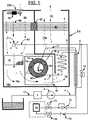
図1は、例えば、負荷する電力を供給するための水素リッチ燃料電池としても良い装置14によって消費されるための水素リッチ燃料源1から精製水素を発生するための装置の簡素化した図面である。図1に示した例示的な実施形態は、関連する構成部品と組み合わせた外側ハウジング36のような適当な支持部材内に独特の水素精製装置18を含んでいる。 FIG. 1 is a simplified drawing of an apparatus for generating purified hydrogen from a hydrogen-
図1の装置は、発生源1からの燃料/水供給原料を処理するように作動することができる改質器圧力容器ユニット19を有している蒸気改質器を含んでいる。燃料と水とのための共通のポンプが予め混合された供給原料としての燃料と水とが混和性である場合として図示されているけれども、燃料と水との流れが触媒が充填されたチャンバ7に到達する前に合流するように、1以上のポンプが各々あらゆる必要な流れ及び圧力監視手段と共に使用しても良いことは理解される。圧力容器ユニット19は、内側水素精製装置コアユニット18を含んでいる。圧力容器ユニット19は、内側水素精製装置コアユニット18よりも大きく且つ触媒が充填されたチャンバ7を形成している。 The apparatus of FIG. 1 includes a steam reformer having a reformer
発生源1からの燃料は、燃料と水との混合物として示されており且つライン17を介してフィルタ2へと引き出され且つポンプ3によってライン4を介して向流熱交換器9へと圧送される供給原料を構成している。供給原料は、熱交換器9において熱を受け取った後に、次いで、熱交換器5において更に多くの熱を受け取り、最終的にライン6によって圧力容器入口接続部60内へ到達する。このようにして、供給原料は触媒が充填されたチャンバ7内に供給され、以下に説明するように加熱され、燃料/水供給原料は反応遊離水素を生成する。ユニット18は、以下に説明する特別な水素選択性透過膜を含んでいる細長い部材であり、水素選択性透過膜は改質されたガスに含まれている水素をユニット18の内側へと透過させ、これに続いて、ユニット18内では精製された水素が水素出口62からライン11へと送られる。ユニット18は概して管状部材として図示されているけれども、ユニット18の形状は、如何なる特別な形状にも限定されず用途に適したあらゆる形状を呈することもできる。ユニット18によって精製されてライン11を通過する水素は、水素出力圧力レギュレータ12内を通過する前に熱交換器9内の供給原料に熱を伝える。ひとたび水素圧力がレギュレータ12によって調整されると、次いで、水素はソレノイド弁13を通過して消費装置14へ入る。消費装置14は必要とされる周期的な抽気を有する燃料電池によって構成することができるので、吹き出しソレノイド弁15及び逆止弁16を通る通路を備えた消費装置14からの戻りラインが含まれており、該ラインを介して吹き出された水素がライン83内へ噴射される。 Fuel from
触媒7の体積及び活性並びにその加熱は、処理された燃料がライン8を介して抜き取られる間にほぼ完全に蒸気改質されるようになされる。
以下においてラフィネートと称される遊離されなかった水素を含む残留燃料及び反応副産物は、ライン8を介して触媒が充填されたチャンバ7から抜き取られる。ラフィネートは次いで熱交換器9内に入って来る供給原料に熱を伝え、その後に、供給原料背圧レギュレータ10内を通過する。ラフィネートは、レギュレータ10を通過する際に減圧され、ライン83を介して燃焼器分配器21へ移動する。The volume and activity of the catalyst 7 and its heating is such that the treated fuel is almost completely steam reformed while it is withdrawn via
Residual fuel and reaction by-products, which are referred to as raffinate in the following and contain unreleased hydrogen, are withdrawn from the chamber 7 filled with catalyst via
触媒燃焼器75は、外側ハウジング36内に取り付けられていて燃焼器空気と混合されたラフィネートを分配器21から受け取る。ラフィネートは、双分配機構として図13に更に明確に示されているような分配器21内の穴を介して空気の流れの中へ排出される。空気とラフィネートとは、燃焼器75への入口において混合されて熱い煙道ガス流75aを精製し、これは隣接するチャンバ内へと通過して上記したように触媒が充填されたチャンバ7を加熱する機能を果たす。
図1に示された装置は、水素の発生及び精製のための改質プロセスの効率及び機能を改良するための特別な特徴を提供している。特に、この装置は、熱交換器9のライン内の加熱された流体及び熱交換器5の下流へ流れる加熱された煙道ガス78aからの種々の熱回収を提供する。 The apparatus shown in FIG. 1 provides special features to improve the efficiency and function of the reforming process for hydrogen generation and purification. In particular, this device provides various heat recovery from the heated fluid in the line of the heat exchanger 9 and the heated flue gas 78a flowing downstream of the heat exchanger 5.
図1に示されているように、ライン4、8及び11の一部分は、改質されたガスからの熱を向流状態で流入して来る供給原料へ戻す向流熱交換ユニット9によって相互に結合されている。これは、効率を改良し且つガスが水素出力圧力レギュレータ12及び供給原料圧力レギュレータ10に到達する前にガスを冷却して装置を熱的損傷から保護する役目も果たす。更に、図1にも示されているように、燃焼器の煙道ガス79と接触しているコイル状に巻かれた熱交換部分5を有するライン4が示されている。熱交換器5は、供給原料を触媒が充填されたチャンバ7内の触媒のための所望の作動温度まで上昇させるような構造とされている。改質器の能力に依存して、熱交換器5は、煙道ガス79からの熱伝達を促進するためにフィンが設けられた管のいくつかの湾曲を含んでいても良いし又は1以上の互いに平行な湾曲部を備えたフィンが設けられていない管によって構成されていても良い。 As shown in FIG. 1, parts of
更に、熱伝導アセンブリ30が、排出チャンバ91及びファン20及び20aの下流の燃焼器空気入口チャンバ90に亘って広がるように配置されている。また、図2aに示されているように、バックアップファン20bをメインのファン20と直列に使用しても良い。アセンブリ30内へ入る熱いガス78aは、アセンブリ30の煙道ガス側の温度を上昇させ、向流状態で空気入口上のアセンブリ30の冷たい部分へ熱を伝達する。より特別には、アセンブリ30は、特に、図2乃至12に示されている図1の装置の好ましい構造において更に十分に記載されるように、各々のチャンバ内の流体が他のチャンバ内へ移るのを熱絶縁密封リング97によって防止する構造とされている。絶縁ガスケット97は更に、アセンブリ30の穿孔された又は伸展編み目金属プレートが種々の温度で作動して向流交換が改良されるようにするのを可能にする。 Further, the heat transfer assembly 30 is arranged to extend across the exhaust chamber 91 and the combustor
図1に示された熱交換器、弁等の配置は特に好ましい配置で示されているけれども、部品の種々の配置が本発明の構成内での同様な結果を達成するために採用されても良く、当業者によって必要とされるように配置しても良い。 Although the arrangement of heat exchangers, valves, etc. shown in FIG. 1 is shown in a particularly preferred arrangement, various arrangements of parts may be employed to achieve similar results within the configuration of the present invention. It may be arranged as required by those skilled in the art.
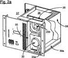
図2乃至4を参照すると、コンパクトな水素発生源ユニット33は、空気供給部分35が横切るように形成されている外側包囲体の壁34(図2a乃至4に部分的に示されている)を含んでおり且つ包囲体36内に包囲されている水素発生ユニットに結合されている。制御部分37は、包囲体36内の空気供給部分35及び水素発生器ユニットの一方の側に配置されている。部分37は、圧力調整装置及びソレノイド弁のような図1に既に記載されている種々の部品を含んでいる。 Referring to FIGS. 2-4, the compact hydrogen source unit 33 includes an outer enclosure wall 34 (partially shown in FIGS. 2a-4) formed by an
空気供給部分35は、空気フィルタ20aを備えたハウジングを含んでおり、該ハウジング内には、空気供給ファン20が該ファン20の下流に設けられたバックアップファン20bと共に配置されている。図2aに図示されているように、バックアップファン20bは軸流タイプであり、メインファン20はブロワータイプである。ファン20は、フィルタ20aを介して空気を引き且つ引いた空気をバックアップファン20bを取り巻いているハウジング内へ吹き付ける。空気通路管38は、バックアップファン20bの外方端部を包囲体36内の水素発生器に接続している。ハウジングの外側面35aはフィルタ20aと穴が開けられた外側表面カバー38bによって覆われている。 The
包囲体36内の水素発生器ユニットは、空気供給部35の後方に取り付けられており且つ堅牢な熱絶縁ベース支持台39a上に載置されている周囲絶縁部材39によって包囲されている。包囲体36内に含まれている高温部分を包囲している絶縁部材は改質器の効率の良い作動を可能にしている。特に、これは包囲体36の最も低温部分に包囲体36に対する金属締結手段を配置することによってなされる。これは、空気通路管38及び包囲体36が締結される図2のユニット33の頂部を含んでいる。これは、熱損失を最少にしつつ装置33の残りの部分への包囲体36の構造的な取り付けを可能にしている。包囲体36内の発生ユニットへの空気の導入は空気通路管38を介してなされる。外周壁絶縁部材39は図示の明確化並びに空気の処理及び好ましい装置の燃料装置の加熱の理解のために部分的にのみ示されている。 The hydrogen generator unit in the
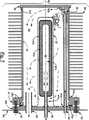
図4乃至8を参照すると、図1の圧力容器ユニット19は、好ましいフィンが付けられた構造で示されており且つ以下において圧力容器40として特定されている。圧力容器40は、内側精製器コアユニット41が中心に配置され且つ固定されている外側外被又は容器42を含んでいる。好ましい実施形態においては、別個のカップ形状保護部材51が外側外被又は容器42と精製容器コアユニット41との間に固定される。保護部材51は、容器42から隔置されており且つ触媒チャンバ7を形成しており且つコアユニット41に対するチャンバ7内の粒状触媒50の当接係合を防止するためにコアユニット41からも隔てられている。 Referring to FIGS. 4-8, the
特に、容器42は、組立前に両端が開口している外側管状壁45を含んでいる。外側端部は、溶接部47a(47aは図6及び7における全ての溶接部を示している)によって管45に対して溶接されている平らな端部壁46によって閉じられており且つカップ形状の保護部材51及び精製器ユニット41の内側端部から隔てられている。管45の対向端部又は内側端部は、例えば、溶接部47aによって管45の開口端部に固定されているフランジ部材47を含んでいるヘッダーユニット46aによって閉じられている。ヘッダーユニット46aは、ボルト53によってボルト止めされて銅製の密封リング52aを使用するフランジ部材47に対する密封結合状態にされている。保護部材51及び精製器コアユニット41は、ヘッダー46aに固定されてフランジ47及び外側外被45又は容器42に対する取り外し可能なユニットを形成している。カバー64もまたボルト53を介してヘッダーユニット46aに取り付けられている。 In particular, the
カップ形状の保護部材51は、触媒50を閉じ込め且つ水素ばかりでなくその他のガス状物質の自由な流通を許容するのに適した穴が開いた金属又はその他の適当な材料によって作られている。保護部材51の開口端部は、溶接又はその他の結合手段によってヘッダー46aに固定されている。 The cup-shaped
精製器コアユニット41は、パラジウム又はパラジウム銅合金製のコーティングのような現在知られている材料による外側の水素透過性金属コーティング41bを有している多孔質セラミック本体41aによって形成されて水素選択性の膜と水素精製器コアユニット41とを形成している。改質されたガスは保護部材51を通ってコアユニット41内へと自由に通過する。水素ガスは、外側の水素選択性膜41bを横切る結果としてコアユニット41の内側収集チャンバ41内へと単に通過する。保護部材51は、多孔質の壁、穴が開けられた壁又は遊離水素をその端部へ導く管状部材であっても良く、水素ガスがそこから排出されて膜ユニット内へと流れるようになされている。触媒が選択性の膜ユニットに対して隔てられた関係で取り付けられている1以上の一体式の触媒部材の形態である場合には、保護部材51は必要でないかも知れない。 The purifier core unit 41 is formed by a porous
図7aを参照すると、フランジ47は、管45の外方端部を周囲の凹所に載置され且つ入れ子式に嵌合されており且つ符号47aのような管45の外側に溶接されている。ヘッダー46aは、フランジ47との間に高圧密封ガスケット52aを挟んでフランジ47にボルト止めされている。図示されている密封接合(図7a)は、フランジ47とヘッダー46aとの間に配置された銅製の密封リング52aを含んでいる。尖った密封端縁52cはフランジ47及びヘッダー46aから外方へ突出していて固定ボルト53を締め付けると銅製リング52aに埋設係合する状態となる。この密封によって、高圧の閉塞が達成されて精製されたガスを容器40内に閉じ込めることができる。他の適当なシールもこの好ましい装置において使用することができ、他の装置においては取り外し可能なカバー構造無しで構成しても良い。例えば、端部部品46aは、圧力容器40の永久的な閉塞のために管45の端部に溶接又は鑞付けしても良い。 Referring to FIG. 7a, the
入力/出力ラインは、ヘッダー46a内に密封され且つ以下に述べるように図示された実施形態のコアユニット41及び触媒チャンバ7内のいくつかの通路に結合されている。
供給原料ライン60はヘッダー46aに対して密封された関係で固定されている。燃料ライン60は、触媒が充填されたチャンバ7内へと内方へ延びており且つ触媒50内を通ってチャンバの内側端部へと延びている。ライン60の内側端部は、端部壁46の近くで終端していて適当な圧力によって水素リッチ供給原料を触媒が充填されたチャンバ7の閉塞端部内へ給送し、供給原料を触媒50内を軸線方向にヘッダー46aに向かって移動させる。本発明の範囲に含まれる代替的な構造(図示せず)は、供給原料給送管60及びラフィネート出口管63とを使用しており、ラフィネート出口管63は、触媒床7の長さ方向に延びており、管は端部が閉じられており且つ穴が開けられていて、触媒床の軸線方向長さに沿って下方に流れるのではなく穴が開けられた管同士の間を流れるようになされている。当業者に明らかである圧力容器内の他の構造も同様に装備することができる。The input / output lines are sealed in
The
水素回収ライン62は、ヘッダーに固定されており且つコアユニット41の内側コアチャンバ41cにおいて終端しており且つ精製コアユニット41の部材41b内を通過した遊離水素を回収する役目を果たす。 The
ラフィネートライン63は、触媒チャンバ7の下方又は底側と整合した状態でヘッダー46aに固定されている。加圧された供給原料は、触媒50内を通過し且つ圧力を受けてラフィネートとしてラフィネートライン63を通って出て行く。ラフィネートは、高いレベルの水素を含んでおり且つ以下に説明するように空気通路内の触媒燃焼器のための燃料として機能する。 The
精製器ユニット41の下流の触媒の出口におけるラフィネートは、触媒又はその他の燃焼器ユニットに燃料を提供することができる。改質されなかった燃料、回収されなかった水素及び一酸化炭素又はメタンのような反応副産物は、触媒又はその他の燃焼器内で燃料として機能する役目を果たすことができる。ラフィネート内に含まれているガスの特色は、燃料のタイプ、蒸気対炭素の比率、圧力、触媒のタイプ、流速及び温度に依存し且つ触媒の流れ上にある時間に依存して変化するかも知れない。精製器41によって水素が除去された改質された供給原料は、ここでは総称的にラフィネートとして特定されており、これは、触媒ユニット及び個々に開示されている装置燃焼器に結合された水素精製ユニットを出て行く改質された供給原料ばかりでなく、別個の燃料源と組み合わされるか又は置き換えられた場合にはこのような燃料の全てを包含するであろう。 The raffinate at the catalyst outlet downstream of the purifier unit 41 can provide fuel to the catalyst or other combustor unit. Unreformed fuel, unrecovered hydrogen and reaction by-products such as carbon monoxide or methane can serve as fuel in the catalyst or other combustor. The characteristics of the gas contained within the raffinate may depend on the fuel type, steam to carbon ratio, pressure, catalyst type, flow rate and temperature, and may vary depending on the time over the catalyst flow. Absent. The reformed feedstock from which hydrogen has been removed by the purifier 41 is here identified generically as raffinate, which is a hydrogen purifier coupled to the catalyst unit and the individually disclosed apparatus combustor. It will include not only the reformed feed leaving the unit, but all such fuels when combined or replaced with a separate fuel source.
容器42及び特に管状の壁45は、例えば、鑞付け又はその他の熱伝導結合によって容器の壁45に密接して固定された隔置された熱伝導フィン59を有している。フィン59は、以下に説明されるように、触媒の理想的な加熱及び精製された水素の発生のために包囲体内の対応する穴内に嵌合する形状に形成されている矩形部材として示されている。フィン59同士は、互いに隔てられており且つ横方向に通過する煙道ガスの流れのための最少の圧力低下を生じつつ容器の迅速な加熱を提供するように選択された大きさ及び配置となっている。フィン59は、容器特に触媒50への迅速な熱伝導のために銅のような適切な材料によって形成されるのが好ましい。 The
圧力容器40(図4)は、取り付けねじ65aによってヘッダー46a及び包囲体のフレーム構造に固定されたプレート64によって包囲体36内の穴65内に取り外し可能に固定されている。フィン付きの容器40は、内側壁構造内に包囲されて以下に説明する空気/燃料の入口通路及び外側排出通路を形成している。 The pressure vessel 40 (FIG. 4) is detachably fixed in the hole 65 in the
フィン付きの圧力容器40及び特に該圧力容器の精製器コアユニット41は、コーティング41bの破壊又はその他の劣化が生じた場合又は粘結化、毒作用、経年化又はその他の理由により触媒の活性が著しく劣化した場合に交換する必要があるかも知れない。その他の構成部品は長寿命を有するものと期待される。 The
図示されているように、フィン付きの圧力容器40はユニットとして取り外し可能である。図示されたヘッダー46aは、フランジ47から解放することができ且つフィン付きの容器42内で新しいコアユニット及び保護部材ユニットと交換することができる。触媒もまたこの作業中に交換することができ、これは、触媒が符号50として図示されている粒状材料ではなく一体の管状部品として形成されている場合には特に簡単である。このようにして、図示されたユニットは、改質器の簡単な実用性及び長寿命の作動のための低コストによって交換できる精製器41及び圧力容器40を提供する。 As shown, the
供給原料給送ライン60、水素(H2)回収ライン62及びラフィネートライン63は、供給原料を入力し且つ図8及び9に示されているような容器42に対して精製された水素及びラフィネートを抜き取るために隔置された関係でヘッダー46aに固定されている。各ラインは、ユニットを修理するときに解放され且つ後に再密封しても良い同様のライン結合ユニット67と同様に構成されている。
ラフィネートライン62は更に、ライン63を開くためにヘッダー46aと結合部67との間に比較的大きな解放可能な結合部68を有していても良い。これは、周期的に必要とされるように粒状触媒50と置換するための一般的な手段を提供する。既に述べたように、触媒は1以上の一体部材によって構成されているときに、ヘッダー46aは、結合部68が不必要になった場合に一体の触媒を交換するために取り外さなければならない。 The
圧力容器40は、図4、8、9乃至9bに示されているように締め付けねじ65aによって包囲体36内に取り外し可能に取り付けられている。ハウジング包囲体36は更に、加熱ガスを包囲体の中に導くために種々の内側壁及び流れ配向手段を含んでいる。図9bに最も良く示されているように、上方の垂直分割壁69は、入口プレナム90を排出ガスプレナム91から分割し、当接回収熱交換器アセンブリ30と包囲体36ばかりでなく包囲体36の側部との間に延びていてプレナム90と91との間に効率の良いバリアを形成している。伝熱式熱交換器30の下方において、堅牢な熱絶縁垂直分割壁70は更にガスの流れを分割する。垂直壁70は、堅牢な熱絶縁水平壁71に当接して該壁71に対して密封している。水平壁70は、混合された空気とラフィネートとが触媒燃焼器75内へ流れ込むのを許容する穴74を含んでおり、さもなければ、水平壁71は、別の場所でのガスの流れを防止するために外側包囲体36と垂直壁70とに対して当接してこれらを密封している。水平壁71は、包囲体36と底部及び側部並びに容器40の隔置されたフィン50と組み合わせられてフィン59及び容器40の内部を加熱するために煙道ガス75aのための通路74bを形成している。容器40の下流において、堅牢な熱絶縁材料によって形成されて壁71及び包囲体36の側部に当接し且つ密封している垂直の煙道ガス分割壁73は、煙道ガスを通路76を介してその穴78内へ導く。壁73と包囲体36とは更に、熱交換器5を含んでいる煙道ガス79のための垂直通路を形成している。 The
フィン付きの管のいくつかのコイルとして図示されている熱交換器(図9a及び9b)は、以下に説明するように、触媒床へ入って来る供給原料ライン4に結合されている供給原料ライン60内に結合されている。フィン付きの管5は、排出煙道ガス79の一部分が通過する位置に配置されており且つライン6、コネクタ67及び触媒50に到達するライン60へと連続して導入する前に熱交換器5内で供給原料を予め加熱するために有効である。 Heat exchangers (FIGS. 9a and 9b), illustrated as several coils of finned tubes, are connected to a
図1、4、8及び9を参照すると、改質器容器40から燃焼器75へのラフィネートの供給接続部が供給原料を予め加熱するためにラインの接続部を備えた状態で図示されている。ラフィネートライン63は、容器40を出て結合部68及び67を通ってラフィネートライン8へと続いている(図1)。ラフィネートライン8は熱交換器9を通過し、次いで供給原料/ラフィネート背圧レギュレータ10を含んでいる制御部分37内へと通過している。背圧レギュレータ10は、該レギュレータが燃焼器給送ライン83に到達する前に燃料電池引き出し水素と結合される場所においてラフィネートを減圧する。燃焼器供給ライン83は次いで包囲体36内へと通過して燃焼器分配器へと通過する。例示的な燃焼器分配器が図13に示されており、これは、T字形管継手86及び穴が開けられた2つの分配器85及び85aを示している。分配器85及び85aは図9、9a及び9bにおいても同様に示されており、これらの図面においては、これらはラフィネートを燃焼器75に到達する前に流入して来る燃焼器と混合するように配置されている。 Referring to FIGS. 1, 4, 8 and 9, the raffinate supply connection from the
管85乃至85aの各々は中空であり且つ最も外方端部が密封されている。管85乃至85aの各々は、セラミック材料、焼結金属又は穴が開けられた管又はその他の同様な機能材料のような多孔質又は穴が開けられた材料であるのが好ましい。装置の作動の開始時においては、通路74内の入口空気74aは比較的冷たい空気であり、触媒床が供給原料を処理するのに十分な温度となるまでラフィネートは発生され得ない。触媒床の作動を開始させ且つ燃焼器75をラフィネートの触媒による燃焼を可能にするのに十分な温度まで予め加熱するために、補助的な加熱源が通常は始動中に必要とされる。燃焼器75の上方に取り付けられた電気ヒーター88が示されている(図9乃至9a)。ヒーター88は、触媒燃焼器温度を“着火”温度まで上昇させ且つ触媒床を燃料を改質するのに十分な温度まで上昇させるために必要な温度まで入口供給空気を加熱するために装置の始動中に自動的にオンされる。ひとたびこの温度に達すると、ポンプ3は、供給原料を装置内へ圧送し始め、触媒50内での水素遊離反応及び燃焼器75の着火のための後続するラフィネート燃料の発生をもたらす。アルコールに基づいた供給燃料のために、必要な触媒床温度は、燃料及び触媒の選択に依存して250ないし500℃程度であり、ラフィネート内の水素のための触媒燃焼器着火温度は約100℃以上である。燃焼器において“着火”状態が達成された後に、入口供給空気の加熱のためのヒーター88は終了されても良い。なぜならば、燃焼器75に入るラフィネートは、次いで、触媒の適切な加熱を維持するのに適しているからである。好ましい構造において記載されている供給原料の予加熱は更に、着火後の補助熱源無しで触媒内に適正なリアクタンスを維持する。 Each of the tubes 85-85a is hollow and sealed at the outermost end. Each of the tubes 85-85a is preferably a porous or perforated material such as a ceramic material, sintered metal or a perforated tube or other similar functional material. At the beginning of operation of the apparatus, the
ラフィネート(図9及び9b)は、空気入口通路74内で空気流と混合され、この混合物は燃焼器75内へ及び該燃焼器内を通過し、燃焼器75は、燃焼して高温流体又は煙道ガス75aを形成する。煙道ガス75aは、入口通路74b内へと直に流入し、図4、8及び9bに示されているように圧力容器40へ且つ該圧力容器上を流れる。加熱された煙道ガス75aは、フィン内を通過し、供給又は入口通路74bからの唯一の出口としての圧力容器40の容器42の上方を通過する。フィン59は、触媒50を加熱し且つそれによってコアユニット41内に捕獲するための水素を発生するために、圧力容器40内に熱を移動させるために適切に隔てられている。既に述べたように供給原料は予め加熱されるけれども、改質反応は、水素を生成するための吸熱反応を保証するために燃焼器からの付加的な熱入力を必要とする。 The raffinate (FIGS. 9 and 9b) is mixed with the air stream in the
触媒50の加熱は、触媒床又は触媒ユニットの軸線上の特別な分配を含んでいても良い。理想的な熱分布曲線100と結果的に得られる反応曲線101とが図12に示されている。熱分布曲線100は触媒50の最初の約半分に亘って高く、触媒の出口又は排出端部に隣接した位置での低レベルまで徐々に低下する。なぜならば、吸熱反応の大部分は触媒床の初期において起こるからである。結果的に得られる遊離水素を発生するための反応曲線101は、高温の入力部分においては水素の急速な増加を含み、次いで、触媒50の出口又は排出端部まで若干のリリース曲線へと水平に進む。 Heating of the
加熱要件は触媒床の最初の部分で比較的高いので、触媒床の出口と比較してこの領域では比較的高い熱流束が望ましい。これは、供給原料入口のより近くにおけるフィン同士の間隔を狭めるか又は供給原料入口の比較的近い位置で煙道ガス75aの温度を増すか又はこれらの組み合わせにより達成される。 Since the heating requirements are relatively high in the first part of the catalyst bed, a relatively high heat flux is desirable in this region compared to the catalyst bed outlet. This is accomplished by reducing the spacing between the fins closer to the feedstock inlet or increasing the temperature of the
図13は、容器の理想的な熱分布のための燃焼器75へのラフィネート入力の特別な構造を示している。部分85及び85aでのラフィネートの分配穴は触媒床7の供給原料入口端部の比較的近くに比較的リッチなラフィネート/空気混合物を供給する一方で出口端部85及び85aはより少ない穴を有して比較的リーンなラフィネート/空気混合物を提供するように変化せしめられている。従って、ほぼ図示に従って、最もリッチで従って最も熱い煙道ガスが触媒床7の入口端部に適用され、最もリーンで且つ最も冷たい煙道ガスが触媒床7の出口端部に適用される。 FIG. 13 shows the special structure of the raffinate input to the
代替的な構造においては、触媒燃焼器は、容器の表面上又は容器に固定されたフィン上に存在していても良い。コーティング方法によって触媒表面を形成するための方法は当業者に知られているので更に詳細には説明しない。触媒燃焼器がフィン上にコーティングされている場合には、フィンは触媒ユニットの長さに沿って互いに近接し且つ隔置されるのが好ましい。このことは、未燃焼のラフィネートがフィンを通り過ぎて滑らず且つ出て行く沿道ガス79によって排出通路76内へと流れ込むのを確保するために必要である。この場合には、図13に示された段階的な燃焼器ディフューザを使用することも好ましい。 In alternative constructions, the catalytic combustor may be on the surface of the container or on fins secured to the container. Methods for forming catalyst surfaces by coating methods are known to those skilled in the art and will not be described in further detail. Where the catalytic combustor is coated on the fins, the fins are preferably adjacent and spaced apart from each other along the length of the catalyst unit. This is necessary to ensure that the unburned raffinate does not slip past the fins and flows into the discharge passage 76 by the exiting roadside gas 79. In this case, it is also preferable to use the staged combustor diffuser shown in FIG.
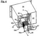
フィン付きのユニット5として図示されている好ましい供給原料熱交換器が図4、8及び8aに示されている。結合部を介して容器40を出て行くライン8及び11は、冷たい供給原料ライン4の金属管によって組み立てられて正確に当接する係合状態とされている長い裸金属管を含んでいる。裸金属管は、適当な結合部好ましくは例えば84cにおけるように実質的な長さに亘って3つの管を相互に鑞付けするか又は溶接すること又はさもなければ似た方法で管同士を他の熱伝導及び結合材料によって当接且つ熱伝導係合状態に保持されている。接合された管4、8及び11は、接合された管の外周を絶縁布84bからなる外側包装材によって覆っても良い。結合されたラインは、ライン8及び11の最も冷たい端部に当接する供給原料ライン4の最も冷たい端部によって向流アセンブリとして組み立てられている。これは、熱損失を最少化して改質器の効率を上げる。熱交換器5はまた、レギュレータ12及び10に到達する前に水素及びラフィネートを冷却する役目を果たす。レギュレータ12及び10は、各々、レギュレータの過熱を防止し且つより低コストで作動温度が比較的低いレギュレータを可能にする。 A preferred feedstock heat exchanger, illustrated as a finned unit 5, is shown in FIGS. 4, 8 and 8a.
結合されたライン4、8及び11は、伸長された長さを形成するために等しい側方端部を有するU字形状構造で示されている。脚部の全長は、容器40と内側コアユニットとの長さに関連し且つほぼ対応していて、熱交換ユニットが容器40並びに入口及び出口による装置の大きさのみならず以下に説明する装置の縮小拡大のための大きさとされ又は縮小拡大されるようになされている。 The joined
これはまた、供給原料の加熱のための比較的簡素であるが効率が極めて高い装置をも提供している。ラインを相互に結合するその他の装置を使用しても良い。供給原料の加熱及び予加熱の回復の結果として、精製された水素の効率の良い発生のための触媒床の必要とされる加熱が減じられ、熱交換器の向流構造は効率を増大させる。 This also provides a relatively simple but extremely efficient apparatus for heating the feedstock. Other devices that connect the lines together may be used. As a result of the heating of the feed and recovery of preheating, the required heating of the catalyst bed for efficient generation of purified hydrogen is reduced and the countercurrent structure of the heat exchanger increases efficiency.
図8乃至9bに示されているように、空気入口プレナム90が壁60の一方の側部に形成されており且つ包囲体36の頂部の半分に亘って延びている。同様に、包囲体36の頂部の残りの半分は、分割壁69の反対側に排出チャンバ91を含んでいる。フィン20からの周囲大気は空気入口38を介してプレナム90内に到達し、プレナム91を出て行く排出物は排出穴92から出て行く。 As shown in FIGS. 8-9b, an
図1及び8乃至9bに示されているような好ましい構造に従って、熱回収構造30は、以下のように、向流形態で排出煙道ガス78a内の熱を空気入口38内に到達する空気に結合させる。 In accordance with the preferred structure as shown in FIGS. 1 and 8-9b, the heat recovery structure 30 causes the heat in the exhaust flue gas 78a to flow to the air reaching the
図1、8及び9の空気入口チャンバ90は、図2a乃至3に示されている空気供給管又は通路38に接続されている。排出チャンバ91は、図3、8及び9bに示されているように、後方構造壁内に排出穴92を含んでいる。 The
多プレートアセンブリ30は、入口空気及び排出煙道ガスの流れの範囲に亘って延びている壁69の下方に固定されている。
図10及び11は、流入して来る供給空気を加熱するための熱回復装置の一つの好ましい構造を明確に示すために拡大されたプレート96を備えた熱伝導プレートアセンブリの拡大図である。多プレートアセンブリ30は、熱絶縁及び流体閉塞壁ガスケット部材97によって分離されている複数の熱伝導プレート96を含んでいる。熱絶縁及び流体閉塞壁ガスケット部材97は、プレート96が流入して来る空気及び出て行く煙道ガスの領域を通過し且つ広がるのを許容しつつ流入して来る空気の出て行く煙道ガスからの分離を維持する。プレート96は、良好な熱伝導材料である銅、アルミニウム又はその他の材料のような適切な金属の同様のプレートとして形成しても良い。図示されているダイヤモンド形状の穴96又はその他のあらゆる形状の穴を該金属プレート内に形成しても良い。これらの穴は、同じ形状又は大きさを有する必要はなく、必ずしも相互に整合された隣接するプレート内の穴である必要もない。これらのプレート内の穴の大きさ及び間隔は、各々のガス流内で最少の圧力低下によって空気及び煙道ガスが容易に通過するのを許容するのに十分な大きさとされている。これらの穴はまた、プレートへ及びプレートから熱を伝達するための大きな表面積をも許容する。The multi-plate assembly 30 is secured below a
FIGS. 10 and 11 are enlarged views of a heat transfer plate assembly with an
プレート96と壁部材97とは薄い部材であるのが好ましい。典型的には、プレート96は0.005〜0.100インチ(0.127〜2.54ミリメートル)、より好ましくは0.020〜0.05インチ(0.508〜1.27ミリメートル)の厚みを有している。プレートの厚みは、煙道ガスからの熱を流入して来る空気に伝達しつつ低い温度低下を生ずるのに十分な大きさとされており且つ使用される金属及びプレート内で必要とされる所望の熱流束に幾分依存する。分離壁部材97は、類似した厚みを有していても良いし又は所望ならばプレートよりも厚くても良い。膜97の絶縁特性は、隣接するプレート96を十分に熱的に絶縁するように選択され、このことは、プレートを種々の温度で作動させて2つのガス流間の向流熱交換を可能にする。従って、最も熱い煙道ガス78aと接触している最も下方のプレートは温度が最も高く、一方、流入しつつある周囲大気と接触している最も上方のプレートは温度が最も低い。 The
図10に示されているように、分離壁部材97は、熱回復アセンブリ30内でのプレート96同士の平行な整合を促進しない。このために、図11に示されているように、部材97aは伸長している脚部97bによって増大されている。このように、アセンブリ30を形成するために複数の部材97及び96を重ねることによってプレート96の平行整合が強制される。 As shown in FIG. 10, the
図示されていないけれども、向流熱交換部材30の他の実施形態が可能である。例えば、環状構造においては、密封部材97はドーナツ形状となり、伸長脚部97bはもはや熱伝導のためにプレートが内側の環と外側の環との間に延びているプレート96の平行な配向を提供する必要はない。更に別の構造においては、2つの別個の穴が開いたプレートを折り畳んで平行なプレートを生じる蛇行パターンとしても良い。これら2つの部品は、分割部材97として作用する薄い金属片によって鑞付けされても良い。平行なプレートの1つの蛇行アセンブリは空気プレナム内へと延びており、一方、他方は煙道ガスプレナム内へと延びており、プレナム間の熱伝導は単一の金属分割部材97の上方の鑞付けされた接合部において生じる。他の付加的な変更例が当業者には自明であろう。 Although not shown, other embodiments of the countercurrent heat exchange member 30 are possible. For example, in an annular configuration, the sealing
一般的に、図示された実施形態は、燃焼器75に供給される供給入力空気を予め加熱するための好ましい構造を開示している。実際的なアセンブリは、本発明の最も広い範囲内で、分離壁内に密封された関係で部材を取り付けることによって入力空気への排出ガス内の熱の効率の良い熱伝導を提供するプレート又はその他の部材を含む必要があるだけである。 In general, the illustrated embodiment discloses a preferred structure for preheating the supply input air supplied to the
排出ガス内の熱を回収するための構造は、チャンバ並びに関連する空気及び排気通路の比較的大きな流通断面積ばかりでなく同様の大きな穴を形成している熱伝導プレート又はその他の熱伝導部材内の比較的大きな穴を含んでいて、この構造が低い圧力低下及びファン20を介して空気を供給するための結果的な低い電力消費をもたらすべきである。 The structure for recovering heat in the exhaust gas is within a heat conducting plate or other heat conducting member that forms a similar large hole as well as a relatively large flow cross section of the chamber and associated air and exhaust passages. This structure should provide a low pressure drop and resulting low power consumption for supplying air through the
同様の考え方が、圧力容器40の加熱に関連する通路に対してなされる。従って、触媒燃焼器75は、比較的大きな断面積を有し且つその中を通る空気/燃料の流れの方向に実質的に複数の同様の平行な通路が形成されている。 Similar considerations apply to the passages associated with heating the
例えば、平方インチ(6.45平方センチメートル)当たり200程度の小室を有する通路を有しており且つ貴金属コーティングを有する押出セラミックによって作られた深さが2インチ(5.08センチメートル)の燃焼器は、公知の構造による比較的満足度の高い燃焼器の一つの例である。入力空気を加熱するための伝熱式熱交換器は、同様に、40%にほぼ等しい開口面積を有する編み目状に伸展され且つ圧延されたパターンのアルミニウムによって作られる。 For example, a 2 inch (5.08 centimeter) deep combustor made of extruded ceramic with a passage having about 200 chambers per square inch (6.45 square centimeters) This is an example of a combustor with a relatively high satisfaction according to a known structure. The heat transfer heat exchanger for heating the input air is likewise made of a pattern of aluminum that is stretched and rolled into a stitch with an open area approximately equal to 40%.
圧力容器40は、比較的大きなフィン付きの構造によって同様に構成されるのが好ましく、熱交換器5のように容器の上方を通過するガス内に低い装置の圧力低下を達成するためにフィン同士の間に適切な間隔を有している。 The
供給原料燃料の予加熱並びに装置内の精製された水素及び改質されたガスからの熱の回収のようなその他の熱回収装置もまた、有効で且つ改良された改質装置を製造する際に重要な結果をもたらす。 Other heat recovery devices, such as preheating feedstock fuels and recovering heat from purified hydrogen and reformed gas in the device, are also useful in producing effective and improved reformers. With important consequences.
空気入口及び排気通路に設けられた熱交換器、供給原料予加熱コイル、結合された流通ライン、触媒燃焼器並びにフィン付きの圧力容器を含んでいる特別な空気及び燃料の供給装置と組み合わせられた構造は、極めて低い燃焼器ガスの圧力低下を生じるかも知れない。その結果、ユニット内へ及び該ユニットを通るように空気及び煙道ガスを動かすための電力要件は低い。このことは、低い熱損失と組み合わせて対応する改質器の効率の増大を生じる。 Combined with special air and fuel supply equipment including heat exchangers in the air inlet and exhaust passages, feedstock preheating coils, combined flow lines, catalytic combustors and finned pressure vessels The structure may result in a very low combustor gas pressure drop. As a result, the power requirements for moving air and flue gas into and through the unit are low. This in combination with a low heat loss results in a corresponding increase in the efficiency of the reformer.
図示された設計の独特の特性はまた、種々の最大出力レベルを有する装置のコスト効率の良い拡大縮小可能な構造をも可能にする。直線軸線を有する図示された実施形態のいくつかの構成要素及び部品は、構成部品の直線長さを所望の容量に直接関係付けられるように設計することによって異なる容積の容器の構造を可能にする。このようにして、燃焼器領域、熱交換領域、触媒体積、精製器膜領域、排出熱伝導装置、供給原料ラインをラフィネートライン及び/又は水素ラインに接続する向流加熱ユニットを含む相互作用する構成部品の各々が、ここに開示されている部材及び構成部品の直線軸線上の長さ従って最終的な構造に直接関係付けられる。 The unique characteristics of the illustrated design also allow for cost-effective scalable structures for devices with various maximum power levels. Some components and parts of the illustrated embodiment having a linear axis allow for the construction of different volume containers by designing the linear length of the component to be directly related to the desired volume. . In this way an interacting arrangement comprising a combustor zone, heat exchange zone, catalyst volume, purifier membrane zone, exhaust heat transfer device, countercurrent heating unit connecting the feed line to the raffinate line and / or hydrogen line Each of the parts is directly related to the length along the linear axis of the members and components disclosed herein and thus to the final structure.
例えば、圧力容器の長さが2倍である場合には、排出チャンバ、入口空気供給及び供給原料熱伝達ユニット及び燃焼器とこれに関連する通路の長さは2倍であって2倍の出力量を生成するであろう。 For example, if the length of the pressure vessel is doubled, the length of the discharge chamber, inlet air supply and feedstock heat transfer unit and combustor and associated passages are doubled and doubled. Will generate competence.
装置の設計及び構造は、拡大縮小の容易性を許容する点で特に独特であるが、コスト効率の高い運転構造をも提供する。精製器においては、膜と触媒構成要素とは、定期的な交換を必要とし且つ好ましい実施形態において容易に交換できるかも知れない。このようにして、この分野における運転は、精製器ユニット及び触媒を含んでいるフィン付きの圧力容器全体を簡単に且つ容易に交換すること又はフィン付きの容器及びフランジユニットを再使用しつつヘッダーに取り付けられるように保護部材及びコアユニットを交換することを含むこともできる。 The design and structure of the device is particularly unique in that it allows for ease of scaling, but it also provides a cost effective operating structure. In the purifier, the membrane and catalyst components may require periodic replacement and may be easily replaced in the preferred embodiment. In this way, operation in this field can easily and easily replace the entire finned pressure vessel containing the purifier unit and catalyst, or reuse the finned vessel and flange unit in the header. It may also include exchanging the protective member and the core unit to be attached.
図示された実施形態は、種々の供給原料のうちのいずれをも処理することができる。混合可能な水/燃料供給原料を使用している好ましい実施形態において例示したけれども、種々の燃料のために従来技術に開示されているように典型的な原料供給調整ステップに従って燃料の脱硫水の調整等のような種々の他のステップを含んでいても良い別個の燃料及び水の供給手段を採用しても良い。同様に、種々の構成部品の大きさ及び配置は、本開示と調和させて変更しても良い。例えば、膜技術における改良は遙かに小さい膜を可能にするであろうし、触媒における同様の改良はより小さい触媒体積を可能にするかも知れない。 The illustrated embodiment can process any of a variety of feedstocks. Although illustrated in the preferred embodiment using a miscible water / fuel feedstock, the fuel desulfurization water is adjusted according to typical feed supply adjustment steps as disclosed in the prior art for various fuels. Separate fuel and water supply means may be employed that may include various other steps such as. Similarly, the size and arrangement of the various components may be changed in harmony with the present disclosure. For example, improvements in membrane technology will allow for much smaller membranes, and similar improvements in catalysts may allow for smaller catalyst volumes.
LCDディスプレイ22及びオペレータ制御装置23(図2参照)のような典型的なユーザーインターフェース要件による改質器の特別な監視、作動及び制御は、既に開示され且つ当業者に知られているデバイス、ハードウエア、作動状態及びアルゴリズムを含んでいる。一つの典型的な例は、“PC−25C On−Site Fuel Power Plant Servic Manual Volume 1”ONSI Corporation(April 1996)等において見出すことができる。 Special monitoring, operation and control of the reformer according to typical user interface requirements, such as LCD display 22 and operator controller 23 (see FIG. 2), are already disclosed and known to those skilled in the art. Software, operating conditions and algorithms. One typical example can be found in “PC-25C On-Site Fuel Power Plant
一般的に、本発明は、水素を含む種々の流体から精製水素を発生するための改良され且つ独特の改質器構造を提供する。本発明の図示された好ましい実施形態はまた、結果的に得られるコスト効率が良い装置を備えた空気供給装置における低い圧力低下によって作動することができる改質装置をも提供する。 In general, the present invention provides an improved and unique reformer structure for generating purified hydrogen from various fluids including hydrogen. The illustrated preferred embodiment of the present invention also provides a reformer that can operate with a low pressure drop in an air supply with a resulting cost effective device.
Claims (10)
Translated fromJapanese水素を製造するために直線軸線に沿って設けられた触媒床を有している直線状の金属製圧力容器であって、該容器は改質されるべき加圧された燃料を前記触媒床及び改質ガス出口へと導くように構成され且つ供給原料入口が配列されている圧力容器と、
前記触媒床の下流に配置されており且つ改質されたガスを受け取り且つ改質されたガスを水素とラフィネートとに分離するように作動する水素選択性膜と、
前記圧力容器の上流に配置され且つ前記直線状の金属製圧力容器の軸線に対してほぼ直角な経路で前記触媒床を通って加熱された流体の流れを直接排出する加熱ユニットであって、前記加熱された流体の流れは前記触媒床の長さにほぼ対応する長さを有している前記加熱ユニットと、を含む改質器。A reformer for separating and purifying hydrogen from a hydrogen-rich feedstock,
Alinear metal pressure vessel having a catalyst bed provided along a linear axis for producinghydrogen , said vesselcontainingpressurized fuel to be reformed and said catalyst bed and A pressure vessel configured to lead to a reformed gas outlet and having a feedstock inlet arranged;
A hydrogen selectivemembrane disposed downstream of the catalyst bed and operable to receive the reformed gas and separate the reformed gas into hydrogen and raffinate;
A heating unit disposeddirectly upstream of the pressure vessel and for directly discharging the flow of fluid heated through the catalyst bed in a path substantially perpendicular to the axis of the linear metal pressure vessel , And a heating unit, wherein the heated fluid stream hasa length substantially corresponding to a length of the catalyst bed.
前記水素選択性部材は前記直線軸線に沿って前記圧力容器の中心に取り付けられた管形状膜であり、前記膜と前記触媒床との間には、前記膜に対する前記触媒床の結合を防止する保護部材が設けられている、改質器。The reformer according to claim 1, wherein
The hydrogen selective member is a tubular membrane attached to the center of the pressure vessel along the linear axis, and prevents the catalyst bed from being bonded to the membrane between the membrane and the catalyst bed. A reformer provided with a protective member.
前記圧力容器が互いに対向する端部を有しており、一方の端部が閉じており、他方の端部が開いており、前記水素選択性膜と前記保護部材との両方が、密封状態で前記容器の前記他端に解放可能に固定されたヘッダープレートに取り付けられており、入口供給原料、ラフィネート出口及び精製水素の全てが前記ヘッダープレートを通過し、前記水素選択性膜と前記保護部材とが交換のためのユニットとして前記圧力容器から取り外すことができる、改質器。The reformer according to claim 2, wherein
The pressure vessel has ends facing each other, one end is closed, the other end is open, and both the hydrogen-selective membrane and the protective member are sealed. It is attached to a header plate releasably fixed to the other end of the container, and all of the inlet feedstock, raffinate outlet and purified hydrogen pass through the header plate, the hydrogen selective membrane, the protective member, Can be removed from the pressure vessel as a unit for replacement.
前記選択性膜と連通している水素出口ラインを更に含んでおり、前記供給原料内の前記水素リッチな燃料を予め加熱するために前記水素出口ラインと前記ラフィネート出口との両方に向流状態で結合されている、改質器。The reformer according to claim 3, wherein
A hydrogen outlet line in communication with the selectivity membrane, in countercurrent to both the hydrogen outlet line and the raffinate outlet to preheat the hydrogen-rich fuel in the feedstock. Combined reformer.
前記容器に固定され且つ該容器から外方へ突出している一連の互いに隔置されたフィンを含んでおり、該フィンは前記触媒床の加熱のために前記容器に前記加熱された流体の流れからの熱を伝達するように熱伝導性である、改質器。The reformer according to claim 1, wherein
A series of spaced apart fins secured to the vessel and projecting outwardly from the vessel, the fins from the heated fluid stream to the vessel for heating the catalyst bed; A reformer that is thermally conductive to transfer heat.
前記フィン同士は前記触媒床内に均一な熱流束を生成するために前記容器の長さに亘って均一に隔てられている、改質器。The reformer according to claim 5, wherein
The reformer, wherein the fins are uniformly spaced across the length of the vessel to produce a uniform heat flux in the catalyst bed.
前記ラフィネートを減圧するためのラフィネート圧力制御手段と、該減圧されたラフィネートを前記加熱ユニットに供給されつつある空気内に分散させるために前記減圧されたラフィネートの下流に配置された分散部材とを更に含んでおり、
前記分散部材が、前記分配されたラフィネート/空気混合物が前記供給原料入口において比較的リッチであり、前記ラフィネート/空気混合物が前記改質ガス出口において比較的リーンであり、それによって、前記改質ガス出口の近くの前記触媒床と比較して前記供給原料入口の近くの触媒床に単位面積当たりより多くの熱流束をもたらすように配置された1以上の多孔質部材を含んでいる、改質器。The reformer according to claim 1, wherein
Raffinate pressure control means for depressurizing the raffinate; and a dispersing member disposed downstream of the depressurized raffinate to disperse the depressurized raffinate in the air being supplied to the heating unit. Including
The dispersing member is such that the distributed raffinate / air mixture is relatively rich at the feedstock inlet and the raffinate / air mixture is relatively lean at the reformed gas outlet, thereby providing the reformed gas A reformer comprising one or more porous members arranged to provide more heat flux per unit area in the catalyst bed near the feed inlet compared to the catalyst bed near the outlet .
前記圧力容器がハウジング内に取り付けられており、該ハウジングは、該ハウジングを、前記圧力容器の上流に配置された前記加熱ユニットに空気を供給するために垂直壁の一方の側に空気入口チャンバを含んでいる空気入口通路と、前記加熱ユニットからの排出ガスを前記圧力容器の下流に排出するために前記壁の反対側に排出チャンバを含んでいる排気通路とに分割する前記垂直壁を含んでおり、
前記加熱ユニットへの入口空気供給を加熱するための向流排気熱回復装置を含み、該熱回復装置は、熱伝導性材料によって作られた複数の熱伝導プレートであって、各々が、前記垂直壁上に横方向に取り付けられ且つ前記入口と排出通路とを横切って延びており且つ前記プレートを通る本質的に自由な空気の流れと排出ガスの流れとを許容するために複数の分布せしめられた穴を含んでいる前記複数の熱伝導プレートと、前記プレートと前記垂直壁との間に設けられて排出ガス流と入口ガス流との混合を防止し、それによって前記プレートが前記排出煙道ガス流から前記入口空気供給まで熱が流れるのを促進する密封手段と、を含む改質器。The reformer according to claim 1, wherein
The pressure vessel is mounted in a housing, and the housing has an air inlet chamber on one side of a vertical wall for supplying the housing with air to the heating unit disposed upstream of the pressure vessel. Including the vertical wall dividing into an air inlet passage containing and an exhaust passage containing a discharge chamber on the opposite side of the wall for discharging exhaust gas from the heating unit downstream of the pressure vessel. And
A counter-flow exhaust heat recovery device for heating the inlet air supply to the heating unit, wherein the heat recovery device is a plurality of heat transfer plates made of a heat conductive material, each of which is said vertical Mounted laterally on the wall and extending across the inlet and exhaust passages and distributed in a plurality to permit essentially free air flow and exhaust gas flow through the plate. A plurality of heat conducting plates including holes, and provided between the plates and the vertical wall to prevent mixing of the exhaust gas flow and the inlet gas flow, whereby the plate has the exhaust flue Sealing means for facilitating heat flow from a gas stream to the inlet air supply.
前記プレートの各々が、前記入口空気供給と前記排出煙道ガスとの流れに直角な面内に配置されている、改質器。A reformer according to claim 8, wherein
A reformer, wherein each of the plates is arranged in a plane perpendicular to the flow of the inlet air supply and the exhaust flue gas.
前記加熱ユニットによって生成された加熱された流体の流れによって改質されるべき水素リッチな燃料を予め加熱するための第1の熱交換器手段と、
前記圧力容器から出て行く水素とラフィネートとによって改質されるように前記水素リッチな燃料を予め加熱するための第2の熱交換器手段であって、前記第1の熱交換器手段の上流に配置されている前記第2の熱交換器手段と、
前記加熱ユニットによって生成された前記加熱された流体の流れによって前記加熱ユニットに提供される空気を予め加熱するための第3の熱交換器手段であって、前記第1の熱交換器手段の下流に配置されている第3の熱交換器手段と、を含む改質器。The reformer according to claim 1, wherein
First heat exchanger means for preheating hydrogen-rich fuel to be reformed by the heated fluid stream generated by the heating unit;
Second heat exchanger means for preheating the hydrogen rich fuel to be reformed by hydrogen and raffinate exiting the pressure vessel, upstream of the first heat exchanger means Said second heat exchanger means arranged in
Third heat exchanger means for preheating air provided to the heating unit by the heated fluid flow generated by the heating unit, downstream of the first heat exchanger means And a third heat exchanger means disposed in the reformer.
Applications Claiming Priority (2)
| Application Number | Priority Date | Filing Date | Title |
|---|---|---|---|
| US10/263,949US7341609B2 (en) | 2002-10-03 | 2002-10-03 | Reforming and hydrogen purification system |
| PCT/US2003/031487WO2004031073A2 (en) | 2002-10-03 | 2003-10-03 | Reforming and hydrogen purification system |
Publications (2)
| Publication Number | Publication Date |
|---|---|
| JP2006502070A JP2006502070A (en) | 2006-01-19 |
| JP4598529B2true JP4598529B2 (en) | 2010-12-15 |
Family
ID=32042113
Family Applications (1)
| Application Number | Title | Priority Date | Filing Date |
|---|---|---|---|
| JP2004541679AExpired - Fee RelatedJP4598529B2 (en) | 2002-10-03 | 2003-10-03 | Reforming and hydrogen purification equipment |
Country Status (8)
| Country | Link |
|---|---|
| US (2) | US7341609B2 (en) |
| EP (1) | EP1546031A2 (en) |
| JP (1) | JP4598529B2 (en) |
| CN (1) | CN100411972C (en) |
| AU (1) | AU2003282674A1 (en) |
| BR (1) | BR0314535A (en) |
| CA (1) | CA2501137C (en) |
| WO (1) | WO2004031073A2 (en) |
Families Citing this family (49)
| Publication number | Priority date | Publication date | Assignee | Title |
|---|---|---|---|---|
| US20040163313A1 (en)* | 2003-02-20 | 2004-08-26 | Buxbaum Robert E. | Hydrogen generation apparatus |
| US20060156627A1 (en)* | 2003-06-27 | 2006-07-20 | Ultracell Corporation | Fuel processor for use with portable fuel cells |
| US8821832B2 (en) | 2003-06-27 | 2014-09-02 | UltraCell, L.L.C. | Fuel processor for use with portable fuel cells |
| EP1644111A4 (en)* | 2003-06-27 | 2011-02-09 | Ultracell Corp | Annular fuel processor and methods |
| US7569193B2 (en) | 2003-12-19 | 2009-08-04 | Applied Materials, Inc. | Apparatus and method for controlled combustion of gaseous pollutants |
| CN1914118B (en)* | 2004-01-30 | 2010-08-11 | 出光兴产株式会社 | Modifier |
| US7297183B2 (en)* | 2004-09-20 | 2007-11-20 | Idatech, Llc | Hydrogen purification devices, components, and fuel processing systems containing the same |
| US7736599B2 (en)* | 2004-11-12 | 2010-06-15 | Applied Materials, Inc. | Reactor design to reduce particle deposition during process abatement |
| US7354464B2 (en)* | 2004-12-17 | 2008-04-08 | Texaco Inc. | Apparatus and method for producing hydrogen |
| KR20080021697A (en)* | 2005-06-13 | 2008-03-07 | 어플라이드 머티어리얼스, 인코포레이티드 | Waste gas reduction method and apparatus |
| JP4863194B2 (en)* | 2005-09-29 | 2012-01-25 | 株式会社Eneosセルテック | Fuel reformer for fuel cell |
| KR101036734B1 (en)* | 2005-10-31 | 2011-05-24 | 어플라이드 머티어리얼스, 인코포레이티드 | Process reduction reactor |
| WO2007095150A2 (en)* | 2006-02-11 | 2007-08-23 | Applied Materials, Inc. | Methods and apparatus for pfc abatement using a cdo chamber |
| US20070240408A1 (en)* | 2006-04-14 | 2007-10-18 | Ewa Environmental, Inc. | Particle burner including a catalyst booster for exhaust systems |
| US20080271448A1 (en)* | 2007-05-03 | 2008-11-06 | Ewa Environmental, Inc. | Particle burner disposed between an engine and a turbo charger |
| US7566423B2 (en) | 2006-04-26 | 2009-07-28 | Purify Solutions, Inc. | Air purification system employing particle burning |
| US7500359B2 (en)* | 2006-04-26 | 2009-03-10 | Purify Solutions, Inc. | Reverse flow heat exchanger for exhaust systems |
| US20080314035A1 (en)* | 2006-04-14 | 2008-12-25 | Lincoln Evan-Beauchamp | Temperature Ladder and Applications Thereof |
| KR100824527B1 (en)* | 2007-01-09 | 2008-04-22 | 삼성에스디아이 주식회사 | Flat Plate PWR reactor |
| FR2918978B1 (en) | 2007-07-20 | 2010-02-12 | Inst Francais Du Petrole | NOVEL HYDROGEN PURIFICATION PROCESS USING A COMBINATION OF MEMBRANE SEPARATION UNITS |
| US8262752B2 (en) | 2007-12-17 | 2012-09-11 | Idatech, Llc | Systems and methods for reliable feedstock delivery at variable delivery rates |
| KR101403883B1 (en)* | 2008-01-25 | 2014-06-17 | 에스케이이노베이션 주식회사 | A steam reformer using a high-performance metal fiber burner and a hydrogen station including the steam reformer |
| US20090199475A1 (en)* | 2008-02-12 | 2009-08-13 | Genesis Fueltech, Inc. | Reformer and Method of Startup |
| CN101723325B (en)* | 2008-10-29 | 2011-09-21 | 中国石油化工股份有限公司 | Method for recovering low-concentration hydrogen |
| US8038939B2 (en)* | 2009-06-09 | 2011-10-18 | Atrion Medical Products, Inc. | Method and devices for improved disinfection process |
| US8187369B2 (en)* | 2009-09-18 | 2012-05-29 | General Electric Company | Sorbent activation plate |
| US8240370B2 (en)* | 2009-12-18 | 2012-08-14 | Air Products And Chemicals, Inc. | Integrated hydrogen production and hydrocarbon extraction |
| CA2817375C (en)* | 2010-11-08 | 2019-04-30 | Ze Energy Inc. | Gasification furnace, gasification system, reformer and reforming system |
| US8961627B2 (en) | 2011-07-07 | 2015-02-24 | David J Edlund | Hydrogen generation assemblies and hydrogen purification devices |
| US11738305B2 (en) | 2012-08-30 | 2023-08-29 | Element 1 Corp | Hydrogen purification devices |
| US9187324B2 (en) | 2012-08-30 | 2015-11-17 | Element 1 Corp. | Hydrogen generation assemblies and hydrogen purification devices |
| US10717040B2 (en) | 2012-08-30 | 2020-07-21 | Element 1 Corp. | Hydrogen purification devices |
| US20140065020A1 (en) | 2012-08-30 | 2014-03-06 | David J. Edlund | Hydrogen generation assemblies |
| JP6197301B2 (en)* | 2013-02-14 | 2017-09-20 | 日本特殊陶業株式会社 | Hydrogen production equipment |
| FR3027381A1 (en)* | 2014-10-21 | 2016-04-22 | Air Liquide | REFORMING OVEN COMPRISING FINNED REFORMING TUBES |
| DK178933B1 (en)* | 2016-05-31 | 2017-06-12 | Serenergy As | A fuel cell system with an extruded reformer chamber and a method of operation the fuel cell system |
| NO345296B1 (en)* | 2016-07-14 | 2020-11-30 | Zeg Power As | Method and power plant comprising a Solid Oxide Fuel Cell (SOFC) for production of electrical energy and H2 gas |
| KR102397390B1 (en) | 2016-11-09 | 2022-05-16 | 8 리버스 캐피탈, 엘엘씨 | Systems and methods for power generation with integrated hydrogen production |
| WO2019092654A2 (en) | 2017-11-09 | 2019-05-16 | 8 Rivers Capital, Llc | Systems and methods for production and separation of hydrogen and carbon dioxide |
| JP6974205B2 (en)* | 2018-02-09 | 2021-12-01 | 株式会社Soken | Fuel cell system |
| CN109179322B (en)* | 2018-11-09 | 2023-11-10 | 沈阳航空航天大学 | An online methanol reformer that uses engine exhaust heat to produce hydrogen-rich gas |
| AU2020292848A1 (en) | 2019-06-13 | 2022-02-03 | 8 Rivers Capital, Llc | Power production with cogeneration of further products |
| CN111313059A (en)* | 2020-03-26 | 2020-06-19 | 广东能创科技有限公司 | A methanol-water-hydrogen fuel cell generator |
| CN111825057A (en)* | 2020-08-07 | 2020-10-27 | 广东能创科技有限公司 | Temperature control system and temperature control method for palladium tube purifier in methanol water hydrogen generator |
| US12187612B2 (en) | 2021-06-15 | 2025-01-07 | Element 1 Corp | Hydrogen generation assemblies |
| CA3238616A1 (en) | 2021-11-18 | 2023-05-25 | Rodney John Allam | Method for hydrogen production |
| CN116265381B (en)* | 2022-12-12 | 2024-08-09 | 四川创达新能科技有限公司 | Coil assembly, mixed gas preheating device and steam reforming hydrogen production furnace |
| WO2025078974A2 (en) | 2023-10-09 | 2025-04-17 | 8 Rivers Capital, Llc | Systems and methods for producing hydrogen with integrated capture of carbon dioxide |
| CN118083912B (en)* | 2023-12-28 | 2025-03-25 | 江苏常氢科技工程研究院有限公司 | A hydrogen purification device for desulfurization using a metal nano-mesoporous structure catalyst |
Family Cites Families (73)
| Publication number | Priority date | Publication date | Assignee | Title |
|---|---|---|---|---|
| US2947152A (en)* | 1955-11-06 | 1960-08-02 | Philips Corp | Heat exchanger for separating out constituents from a gas by cooling |
| US3607125A (en)* | 1968-12-30 | 1971-09-21 | Gen Electric | Reformer tube construction |
| CH561889A5 (en)* | 1973-04-13 | 1975-05-15 | Schrade Jean | |
| US4430304A (en)* | 1981-11-13 | 1984-02-07 | The United States Of America As Represented By The United States Department Of Energy | Slab reformer |
| EP0227807B1 (en)* | 1985-06-27 | 1991-11-21 | Stone & Webster Engineering Corporation | Production of synthesis gas using convective reforming |
| JPH0642940B2 (en)* | 1987-03-31 | 1994-06-08 | 東洋エンジニアリング株式会社 | Device for gas endothermic reaction |
| US5025856A (en)* | 1989-02-27 | 1991-06-25 | Sundstrand Corporation | Crossflow jet impingement heat exchanger |
| JPH03232703A (en)* | 1989-12-26 | 1991-10-16 | Tokyo Electric Power Co Inc:The | Reformer of hydrocarbon |
| US5215729A (en)* | 1990-06-22 | 1993-06-01 | Buxbaum Robert E | Composite metal membrane for hydrogen extraction |
| US5401589A (en)* | 1990-11-23 | 1995-03-28 | Vickers Shipbuilding And Engineering Limited | Application of fuel cells to power generation systems |
| JP3035038B2 (en) | 1991-11-25 | 2000-04-17 | 三菱重工業株式会社 | Hydrogen production method |
| US5679249A (en)* | 1991-12-24 | 1997-10-21 | Pall Corporation | Dynamic filter system |
| US5198002A (en)* | 1992-03-12 | 1993-03-30 | The United States Of America As Represented By The United States Department Of Energy | Gas stream clean-up filter and method for forming same |
| US6098620A (en) | 1993-01-29 | 2000-08-08 | Aradigm Corporation | Device for aerosolizing narcotics |
| EP0615949B1 (en)* | 1993-03-16 | 1999-09-15 | Tokyo Gas Co., Ltd. | Hydrogen producing apparatus |
| JP3197095B2 (en)* | 1993-03-16 | 2001-08-13 | 東京瓦斯株式会社 | Hydrogen production equipment |
| JP3213430B2 (en) | 1993-03-31 | 2001-10-02 | 日本碍子株式会社 | Gas separator and method for producing the same |
| JPH07153320A (en) | 1993-11-29 | 1995-06-16 | Furukawa Electric Co Ltd:The | Multilayer insulated wire and transformer using the same |
| DE4341438C2 (en) | 1993-12-04 | 2000-07-13 | Binsmaier Hannelore | Modular power plant for the production of mainly hydrogen from solar energy |
| US5580523A (en)* | 1994-04-01 | 1996-12-03 | Bard; Allen J. | Integrated chemical synthesizers |
| JP3599370B2 (en)* | 1994-05-23 | 2004-12-08 | 日本碍子株式会社 | Hydrogen production equipment |
| JPH07315801A (en) | 1994-05-23 | 1995-12-05 | Ngk Insulators Ltd | System for producing high-purity hydrogen, production of high-purity hydrogen and fuel cell system |
| US5484577A (en)* | 1994-05-27 | 1996-01-16 | Ballard Power System Inc. | Catalytic hydrocarbon reformer with enhanced internal heat transfer mechanism |
| US5589599A (en)* | 1994-06-07 | 1996-12-31 | Mcmullen; Frederick G. | Pyrolytic conversion of organic feedstock and waste |
| US5525322A (en)* | 1994-10-12 | 1996-06-11 | The Regents Of The University Of California | Method for simultaneous recovery of hydrogen from water and from hydrocarbons |
| JP3309265B2 (en) | 1995-01-19 | 2002-07-29 | 京セラ株式会社 | Battery charging completion determination method |
| US5738708A (en)* | 1995-06-07 | 1998-04-14 | The Regents Of The University Of California Office Of Technology Transfer | Composite metal membrane |
| JPH092802A (en)* | 1995-06-20 | 1997-01-07 | Tokyo Gas Co Ltd | Hydrogen production equipment |
| US5931987A (en) | 1996-11-06 | 1999-08-03 | Buxbaum; Robert E. | Apparatus and methods for gas extraction |
| US5888273A (en) | 1996-09-25 | 1999-03-30 | Buxbaum; Robert E. | High temperature gas purification system |
| US6461408B2 (en) | 1995-11-06 | 2002-10-08 | Robert E. Buxbaum | Hydrogen generator |
| DE19544895C1 (en) | 1995-12-01 | 1997-02-27 | Daimler Benz Ag | Oxidising carbon mon:oxide in gas mixt. from hydrocarbon reforming plant |
| US5637259A (en)* | 1995-12-04 | 1997-06-10 | Natural Resources Canada | Process for producing syngas and hydrogen from natural gas using a membrane reactor |
| US5741605A (en)* | 1996-03-08 | 1998-04-21 | Westinghouse Electric Corporation | Solid oxide fuel cell generator with removable modular fuel cell stack configurations |
| JPH09283305A (en) | 1996-04-11 | 1997-10-31 | Murata Mfg Co Ltd | Thermistor and method for adjusting resistance value of thermistor |
| US6129861A (en) | 1996-05-10 | 2000-10-10 | Forschungszentrum Julich Gmbh | Membrane reactor for producing CO- and CO2 -free hydrogen |
| US6245303B1 (en)* | 1998-01-14 | 2001-06-12 | Arthur D. Little, Inc. | Reactor for producing hydrogen from hydrocarbon fuels |
| JP4000607B2 (en) | 1996-09-06 | 2007-10-31 | トヨタ自動車株式会社 | Fuel cell power generation apparatus and method |
| US6319306B1 (en) | 2000-03-23 | 2001-11-20 | Idatech, Llc | Hydrogen-selective metal membrane modules and method of forming the same |
| US6221117B1 (en) | 1996-10-30 | 2001-04-24 | Idatech, Llc | Hydrogen producing fuel processing system |
| US6152995A (en) | 1999-03-22 | 2000-11-28 | Idatech Llc | Hydrogen-permeable metal membrane and method for producing the same |
| US6376113B1 (en) | 1998-11-12 | 2002-04-23 | Idatech, Llc | Integrated fuel cell system |
| US5861137A (en)* | 1996-10-30 | 1999-01-19 | Edlund; David J. | Steam reformer with internal hydrogen purification |
| US5997594A (en)* | 1996-10-30 | 1999-12-07 | Northwest Power Systems, Llc | Steam reformer with internal hydrogen purification |
| KR100209989B1 (en) | 1996-12-23 | 1999-07-15 | 남창우 | Natural Gas Hydrogen Generator |
| US6051192A (en) | 1997-04-15 | 2000-04-18 | International Fuel Cells Corporation | Control system and method for controlling a gas generating system |
| US5811065A (en) | 1997-04-24 | 1998-09-22 | Ballard Generation Systems Inc. | Burner exhaust gas collection assembly for a catalytic reformer |
| DE19721630C1 (en) | 1997-05-23 | 1999-02-11 | Fraunhofer Ges Forschung | Device for reforming hydrocarbons containing starting materials |
| EP0992075A1 (en) | 1997-06-06 | 2000-04-12 | Volkswagen Aktiengesellschaft | Fuel cell methanol reformer with an energy storage unit and method for controlling the energy flow of the system |
| US5955044A (en) | 1997-09-30 | 1999-09-21 | Johnson Matthey Inc. | Method and apparatus for making ultra-pure hydrogen |
| JPH11116202A (en)* | 1997-10-16 | 1999-04-27 | Ishikawajima Harima Heavy Ind Co Ltd | Pressurized reformer |
| US5938800A (en)* | 1997-11-13 | 1999-08-17 | Mcdermott Technology, Inc. | Compact multi-fuel steam reformer |
| US6152987A (en) | 1997-12-15 | 2000-11-28 | Worcester Polytechnic Institute | Hydrogen gas-extraction module and method of fabrication |
| EP0924162A3 (en) | 1997-12-16 | 1999-10-20 | dbb fuel cell engines GmbH | Membrane for the separation of hydrogen, methanol reformer using this membrane and process for its operation |
| DE19755813C2 (en)* | 1997-12-16 | 2000-09-14 | Dbb Fuel Cell Engines Gmbh | Process for operating a steam reforming plant, thus operable reforming plant and fuel cell system operating method |
| WO1999034898A1 (en) | 1998-01-06 | 1999-07-15 | The Regents Of The University Of California | Apparatus and method for simultaneous recovery of hydrogen from water and from hydrocarbons |
| DE19920168A1 (en)* | 1998-05-16 | 1999-11-18 | Luk Automobiltech Gmbh & Co Kg | Radial piston pump of camshaft and cylinders for vehicle media |
| US6348278B1 (en)* | 1998-06-09 | 2002-02-19 | Mobil Oil Corporation | Method and system for supplying hydrogen for use in fuel cells |
| JP4192301B2 (en) | 1998-08-03 | 2008-12-10 | トヨタ自動車株式会社 | Control device for reformer |
| DE19843306C2 (en) | 1998-09-22 | 2001-06-28 | Heraeus Gmbh W C | Process for producing a tubular hydrogen permeation membrane |
| US6207132B1 (en)* | 1998-12-04 | 2001-03-27 | Chinese Petroleum Corporation | Process for producing high purity hydrogen |
| EP1024111A1 (en) | 1999-01-19 | 2000-08-02 | Chinese Petroleum Corporation | Process and apparatus for producing high purity hydrogen |
| JP3473900B2 (en) | 1999-05-24 | 2003-12-08 | 松下電器産業株式会社 | Hydrogen generator |
| US6214090B1 (en) | 1999-06-18 | 2001-04-10 | The Regents Of The University Of California | Thermally tolerant multilayer metal membrane |
| US6375906B1 (en) | 1999-08-12 | 2002-04-23 | Idatech, Llc | Steam reforming method and apparatus incorporating a hydrocarbon feedstock |
| US6303245B1 (en) | 1999-08-27 | 2001-10-16 | Plug Power Inc. | Fuel cell channeled distribution of hydration water |
| US6383670B1 (en) | 1999-10-06 | 2002-05-07 | Idatech, Llc | System and method for controlling the operation of a fuel processing system |
| US6242120B1 (en) | 1999-10-06 | 2001-06-05 | Idatech, Llc | System and method for optimizing fuel cell purge cycles |
| US6656617B2 (en) | 2000-01-24 | 2003-12-02 | Toyota Jidosha Kabushiki Kaisha | Fuel gas production system for fuel cells |
| US20010045061A1 (en) | 2000-03-13 | 2001-11-29 | Ida Tech, L.L.C. | Fuel processor and systems and devices containing the same |
| US6835481B2 (en) | 2000-03-29 | 2004-12-28 | Idatech, Llc | Fuel cell system with load management |
| ATE423399T1 (en) | 2000-06-01 | 2009-03-15 | Idatech Llc | FUEL CELLS AND FUEL CELL SYSTEMS WITH NON-AQUEOUS ELECTROLYTES |
| WO2002070402A2 (en) | 2001-03-05 | 2002-09-12 | Shell Internationale Research Maatschappij B.V. | Apparatus and process for the production of hydrogen |
- 2002
- 2002-10-03USUS10/263,949patent/US7341609B2/ennot_activeExpired - Lifetime
- 2003
- 2003-10-03CACA2501137Apatent/CA2501137C/ennot_activeExpired - Lifetime
- 2003-10-03AUAU2003282674Apatent/AU2003282674A1/ennot_activeAbandoned
- 2003-10-03JPJP2004541679Apatent/JP4598529B2/ennot_activeExpired - Fee Related
- 2003-10-03CNCNB2003801047927Apatent/CN100411972C/ennot_activeExpired - Lifetime
- 2003-10-03WOPCT/US2003/031487patent/WO2004031073A2/enactiveApplication Filing
- 2003-10-03BRBR0314535-2Apatent/BR0314535A/ennot_activeApplication Discontinuation
- 2003-10-03EPEP03774560Apatent/EP1546031A2/ennot_activeWithdrawn
- 2008
- 2008-02-20USUS12/034,325patent/US20080134577A1/ennot_activeAbandoned
Also Published As
| Publication number | Publication date |
|---|---|
| US7341609B2 (en) | 2008-03-11 |
| WO2004031073A3 (en) | 2004-08-05 |
| US20080134577A1 (en) | 2008-06-12 |
| CN1720194A (en) | 2006-01-11 |
| CA2501137A1 (en) | 2004-04-15 |
| BR0314535A (en) | 2005-08-02 |
| CN100411972C (en) | 2008-08-20 |
| CA2501137C (en) | 2012-04-24 |
| US20040065013A1 (en) | 2004-04-08 |
| JP2006502070A (en) | 2006-01-19 |
| AU2003282674A1 (en) | 2004-04-23 |
| EP1546031A2 (en) | 2005-06-29 |
| WO2004031073A2 (en) | 2004-04-15 |
Similar Documents
| Publication | Publication Date | Title |
|---|---|---|
| JP4598529B2 (en) | Reforming and hydrogen purification equipment | |
| JP6538764B2 (en) | Hydrogen generation assembly and hydrogen purification device | |
| CN100562485C (en) | Steam reforming fuel processor | |
| US6936363B2 (en) | Ammonia cracker for production of hydrogen | |
| JP3556638B2 (en) | Fuel cell device | |
| US7867300B2 (en) | Ammonia-based hydrogen generation apparatus and method for using same | |
| CA2753213C (en) | Fuel cell systems with vaporizer coils that wrap around the reformer | |
| BRPI0609781A2 (en) | process for preparing hydrogen in a fuel processor assembly and apparatus for producing hydrogen | |
| JPS5884035A (en) | Contact gas reformer | |
| JP2003527279A (en) | Fuel processor and system and device incorporating the same | |
| JP2004531447A (en) | Compact steam reformer | |
| US20070000173A1 (en) | Compact reforming reactor | |
| US20070000172A1 (en) | Compact reforming reactor | |
| JPS62260701A (en) | Raw material reformer | |
| US7267804B2 (en) | Membrane reactor for gas extraction | |
| JP2004175581A (en) | Internal heating steam reformer | |
| JP4278984B2 (en) | Membrane reactor for gas extraction | |
| JPH0640704A (en) | Reactor for dehydrogenation reaction | |
| JPH0891803A (en) | Modifying device of methanol for engine | |
| US20040136883A1 (en) | Membrane reactor for gas extraction | |
| JPH09227103A (en) | Hydrogen production equipment |
Legal Events
| Date | Code | Title | Description |
|---|---|---|---|
| A621 | Written request for application examination | Free format text:JAPANESE INTERMEDIATE CODE: A621 Effective date:20060921 | |
| A131 | Notification of reasons for refusal | Free format text:JAPANESE INTERMEDIATE CODE: A131 Effective date:20090916 | |
| A601 | Written request for extension of time | Free format text:JAPANESE INTERMEDIATE CODE: A601 Effective date:20091215 | |
| A602 | Written permission of extension of time | Free format text:JAPANESE INTERMEDIATE CODE: A602 Effective date:20091222 | |
| A521 | Request for written amendment filed | Free format text:JAPANESE INTERMEDIATE CODE: A523 Effective date:20100118 | |
| A521 | Request for written amendment filed | Free format text:JAPANESE INTERMEDIATE CODE: A821 Effective date:20100118 | |
| TRDD | Decision of grant or rejection written | ||
| A01 | Written decision to grant a patent or to grant a registration (utility model) | Free format text:JAPANESE INTERMEDIATE CODE: A01 Effective date:20100827 | |
| A01 | Written decision to grant a patent or to grant a registration (utility model) | Free format text:JAPANESE INTERMEDIATE CODE: A01 | |
| A61 | First payment of annual fees (during grant procedure) | Free format text:JAPANESE INTERMEDIATE CODE: A61 Effective date:20100924 | |
| R150 | Certificate of patent or registration of utility model | Ref document number:4598529 Country of ref document:JP Free format text:JAPANESE INTERMEDIATE CODE: R150 | |
| FPAY | Renewal fee payment (event date is renewal date of database) | Free format text:PAYMENT UNTIL: 20131001 Year of fee payment:3 | |
| R250 | Receipt of annual fees | Free format text:JAPANESE INTERMEDIATE CODE: R250 | |
| R250 | Receipt of annual fees | Free format text:JAPANESE INTERMEDIATE CODE: R250 | |
| R250 | Receipt of annual fees | Free format text:JAPANESE INTERMEDIATE CODE: R250 | |
| S111 | Request for change of ownership or part of ownership | Free format text:JAPANESE INTERMEDIATE CODE: R313113 | |
| S531 | Written request for registration of change of domicile | Free format text:JAPANESE INTERMEDIATE CODE: R313531 | |
| R350 | Written notification of registration of transfer | Free format text:JAPANESE INTERMEDIATE CODE: R350 | |
| R250 | Receipt of annual fees | Free format text:JAPANESE INTERMEDIATE CODE: R250 | |
| S111 | Request for change of ownership or part of ownership | Free format text:JAPANESE INTERMEDIATE CODE: R313113 | |
| R350 | Written notification of registration of transfer | Free format text:JAPANESE INTERMEDIATE CODE: R350 | |
| R250 | Receipt of annual fees | Free format text:JAPANESE INTERMEDIATE CODE: R250 | |
| R250 | Receipt of annual fees | Free format text:JAPANESE INTERMEDIATE CODE: R250 | |
| R250 | Receipt of annual fees | Free format text:JAPANESE INTERMEDIATE CODE: R250 | |
| R250 | Receipt of annual fees | Free format text:JAPANESE INTERMEDIATE CODE: R250 | |
| R250 | Receipt of annual fees | Free format text:JAPANESE INTERMEDIATE CODE: R250 | |
| S111 | Request for change of ownership or part of ownership | Free format text:JAPANESE INTERMEDIATE CODE: R313114 | |
| S531 | Written request for registration of change of domicile | Free format text:JAPANESE INTERMEDIATE CODE: R313531 | |
| S533 | Written request for registration of change of name | Free format text:JAPANESE INTERMEDIATE CODE: R313533 | |
| R350 | Written notification of registration of transfer | Free format text:JAPANESE INTERMEDIATE CODE: R350 | |
| R250 | Receipt of annual fees | Free format text:JAPANESE INTERMEDIATE CODE: R250 | |
| LAPS | Cancellation because of no payment of annual fees |