JP4598219B2 - Sliding gate valve for granular materials - Google Patents
Sliding gate valve for granular materialsDownload PDFInfo
- Publication number
- JP4598219B2 JP4598219B2JP2000046105AJP2000046105AJP4598219B2JP 4598219 B2JP4598219 B2JP 4598219B2JP 2000046105 AJP2000046105 AJP 2000046105AJP 2000046105 AJP2000046105 AJP 2000046105AJP 4598219 B2JP4598219 B2JP 4598219B2
- Authority
- JP
- Japan
- Prior art keywords
- gate plate
- frame
- air
- gate
- opening
- Prior art date
- Legal status (The legal status is an assumption and is not a legal conclusion. Google has not performed a legal analysis and makes no representation as to the accuracy of the status listed.)
- Expired - Lifetime
Links
Images


Classifications
- F—MECHANICAL ENGINEERING; LIGHTING; HEATING; WEAPONS; BLASTING
- F16—ENGINEERING ELEMENTS AND UNITS; GENERAL MEASURES FOR PRODUCING AND MAINTAINING EFFECTIVE FUNCTIONING OF MACHINES OR INSTALLATIONS; THERMAL INSULATION IN GENERAL
- F16K—VALVES; TAPS; COCKS; ACTUATING-FLOATS; DEVICES FOR VENTING OR AERATING
- F16K3/00—Gate valves or sliding valves, i.e. cut-off apparatus with closing members having a sliding movement along the seat for opening and closing
- F16K3/02—Gate valves or sliding valves, i.e. cut-off apparatus with closing members having a sliding movement along the seat for opening and closing with flat sealing faces; Packings therefor
- F16K3/0227—Packings
- F—MECHANICAL ENGINEERING; LIGHTING; HEATING; WEAPONS; BLASTING
- F16—ENGINEERING ELEMENTS AND UNITS; GENERAL MEASURES FOR PRODUCING AND MAINTAINING EFFECTIVE FUNCTIONING OF MACHINES OR INSTALLATIONS; THERMAL INSULATION IN GENERAL
- F16K—VALVES; TAPS; COCKS; ACTUATING-FLOATS; DEVICES FOR VENTING OR AERATING
- F16K3/00—Gate valves or sliding valves, i.e. cut-off apparatus with closing members having a sliding movement along the seat for opening and closing
- F16K3/02—Gate valves or sliding valves, i.e. cut-off apparatus with closing members having a sliding movement along the seat for opening and closing with flat sealing faces; Packings therefor
- F16K3/0281—Guillotine or blade-type valves, e.g. no passage through the valve member
Landscapes
- Engineering & Computer Science (AREA)
- General Engineering & Computer Science (AREA)
- Mechanical Engineering (AREA)
- Sliding Valves (AREA)
- Details Of Valves (AREA)
Description
Translated fromJapanese【0001】
【発明の属する技術分野】
本発明は、粉粒体を輸送する粉粒体輸送路をゲートで開閉する粉粒体用スライド式ゲートバルブ、特に、そのシール構造に関するものである。
【0002】
【従来の技術】
従来、図15及び図16に示す従来技術の通りの粉粒体用スライド式ゲートバルブ501が一例として挙げられ、これは、インレットホッパー540とアウトレットホッパー542とがベースフレーム544によって連結されるとともに開口部503を備えた枠状体504に、エアシリンダ505に連結したゲート板502を収容するゲート板収容体546が連結し、更にこのゲート板収容体546にエアシリンダ505が接続されたものである。そして、ゲート板502とゲート板収容体546とをシールするシール材509(グランドパッキン等を備えたもの)がゲート板収容体546の先端部に固定されている。更に、インレットホッパー540の下側領域にゲート板502を案内するガイドレール513が形成されている。そして、ゲート板502をエアシリンダ505で押し出すことで開口部503を閉鎖し、ゲート板502をエアシリンダ505で縮ませることで、ゲート板502で開口部503を開放するものであり、これにより、上下方向の粉粒体輸送路を開閉可能としている。また、粉粒体用スライド式ゲートバルブ501は、外部のエア設備及び電気設備に接続されている。
ここで、外形が四角型のものは正方形長方形排出口用であり、コンベア、タンク下等の粉粒体の排出に適用され、外形が丸型のものは円形排出口用であり、サイロ、チェックビン下等の粉粒体排出用に適用される態様が例示される。構造が簡単でメンテナンスが容易で、用途に応じたシール方式でシール性を向上させている。
【0003】
ところが、ゲート板収容体546と枠状体504との間の隙間がシールされているものの、粉粒体の移動経路から移動経路外へのシール性が未だ十分でなく、又、枠状体504の内部において、ゲート板502とインレットホッパー540の下端縁の間には、ゲート板502の摩擦抵抗を無くしてスライドを円滑にするとともに、堆積する粉粒体圧を支持するためにゲート板502の強度を確保するためなど、トラブル防止の理由から、隙間が存在し、ゲート板502が閉じられたときでも、前記隙間から上部から下部に向かって粉粒体が漏れ、粉粒体の移動経路内におけるシール性が未だ十分ではないため、エア、粉粒体の漏れ等の不都合が生じている。ゲート板502の上部領域側の圧力がプラス圧である場合には、漏れの量が多くなる。
【0004】
【発明が解決しようとする課題】
そこで、請求項1記載の発明は、ゲート板が閉じられているときの粉粒体の移動経路内での粉粒体の漏れ、或いは、ゲート板の開閉時における粉粒体の移動経路から移動経路外への粉粒体の漏れを防止することを目的とするものである。
【0005】
【課題を解決するための手段】
上記課題に鑑み、請求項1記載の発明は、開口部を備えた枠状体と、該枠状体に配置されたアクチュエータと、前記枠状体と接続された収容ケースと、前記アクチュエータによって粉粒体の移動経路の方向に直交してスライド運動を行うことで前記開口部を開閉するゲート板と、前記枠状体の前記収容ケース側の領域に形成された貫通孔に設けられたシールハウジングにパッキンが圧入され、前記枠状体と前記ゲート板との間をシールすることにより、前記粉粒体の移動経路から移動経路外への漏れを防止するシール部材と、前記ゲート板を支持する支持部材と、を備え、前記アクチュエータがエアシリンダであり、前記シールハウジングに前記エアシリンダの排気を導入してなることを特徴とする粉粒体用スライド式ゲートバルブである。これにより、エアシリンダによりゲート板が駆動される際に排出される排気によってシールハウジング内の圧力が高められ、粉粒体の移動経路から移動経路外への粉粒体の漏れを一層有効に防止でき、シール性を高めることが出来る。シール部材の構造は種々挙げられるが適宜採択できる。ここで、収容ケースはゲート板が開閉する際にこれを収容したり、電気部品、空気圧部品等を収容することもあるものである。支持部材は、ゲート板が閉じられた際に支持するもの、或いは、ゲート板が開閉する際のガイドレール等が該当する。
【0010】
前記支持部材がガイドレールであり、前記ゲート板を下方から支持しながら案内する前記ガイドレールを前記枠状体に前記スライド運動の方向に設け、前記開口部が開閉されるときに前記ゲート板が前記第2のシール部材と前記ガイド部材の間で挟まれながら摺動されるようにしたことが好ましい。これにより、上記課題が好適に達成できる上、ゲート板を閉じたときにゲート板の上部に堆積した粉粒体の荷重によりゲート板がたわんでしまうことを防止し、強度や耐久性を改善することができる。比較的大型のゲート板のスライド運動を円滑にすることが出来る。
【0011】
前記支持部材が前記枠状体の内側領域に設けた2個以上の突部であり、前記ゲート板が前記開口部を閉じるときに、ゲート板を下方から支持することが好ましい。これにより、上記課題が好適に達成できる上、ゲート板を閉じたときにゲート板を支持することで、ゲート板上部に堆積した粉粒体の荷重によってゲート板がたわんでしまうことを防止し、強度や耐久性を改善することができる。
【0012】
【発明の実施の形態】
以下、本発明の第1実施形態の粉体用スライド式ゲートバルブ1(以下、単にゲートバルブ1という)について図1〜図11を参照して説明する。図1乃至図3に示すように、本実施形態のゲートバルブ1は、食品用、医薬品用又は化学品用その他の粉体を輸送する輸送パイプに接続された集塵機、サイクロン、コンベア、タンク、サイロ、チェックビン、ミキサー、スクリューフィーダ等の排出口に接続され、開閉することにより粉粒体を下流側に排出可能としたものである。即ち、ゲートバルブ1は、平面視で略正方形、正面視で長方形、側面視で横長のリング帯状の扁平な小判形状の板材であるゲート板2と、このゲート板2が移動可能な状態に組込まれているケースである開口部3を備えた枠状体4と、ゲート板2を開閉するための流体圧アクチュエータである一対のエアシリンダ5,6と、枠状体4に接続された収容ケース7と、を有している。このゲート板2は、図1の2点鎖線で示す通り、右端が連結ロッド8に固定されていて、左右方向に移動可能な状態で枠状体4に配置されている。エアシリンダ5,6のピストンロッド50,60の先端部は、連結ロッド8に直交して固定されている。エアシリンダ5,6によって、ゲート板2は、所定方向、ここでは水平方向にスライド運動を行い、エアシリンダ5,6の伸張時にゲート板2が収容ケース7に収容されることによって開口部3が開き、エアシリンダ5,6の縮退時にゲート板2によって開口部3が閉じられるようになっている。即ち、エアシリンダ5,6がゲート板2を押して開口部3を開き、ゲート板2を引いて開口部3を閉じる構造である。また、ゲート板2の開閉時に、ゲート板2に粉体が付着したまま収容ケース7に排出されるのを防止するシール部材9(図6参照)を、枠状体4の収容ケース7側の貫通孔に固定し、及び枠状体4とゲート板2の間をシールする四角形枠状のシール部材10を、開口部3の内側周縁、即ち外枠としての枠状体4の内側に内枠として固定してある。収容ケース7には、エア設備ユニット11及び電気設備ユニット13が収容されている。以下、各要素を詳細に説明する。
【0013】
(枠状体4の説明)
枠状体4は、金属製(アルミニウム等)の複数のブロック部材を連結したものである。即ち、図1乃至図3等の通り、枠状体4は、ゲート板2のスライド方向に並行に所定間隔を設けた2つの側枠部材40,41と、側枠部材40,41と直交して端部同士が連結された前方枠部材42及び後方枠部材43とで構成されて、それぞれ、相互にねじ等で連結されたものである。一対のエアシリンダ5,6が側枠部材40,41の外側領域にそれらと平行に設置され、シリンダチューブ51,61の基端部が後方枠部材43の左右両端部に形成されたエアシリンダ固定部43a,43bに固定されるとともに、シリンダチューブ51,61の先端部及び前方枠部材42の前面側が収容ケース7の両端部の固定部70,71(図3参照)に、それぞれ、ねじ等により固定されている。そして、前方枠部材42にはゲート板2が挿通できる長円形状のガイド孔46が形成されている。このガイド孔46にシール部材9を設けている。側枠部材40,41は、ゲート板2の長さよりも短く設定され、断面角形の長尺のブロック材である。前方枠部材42及び後方枠部材43の横幅はゲート板2の幅よりも大きく設定され、断面角形の長尺のブロック材である。図1の通り、ゲート板2が開口部3を閉じたときには、駆動に伴うトラブルの防止のため、隙間Mが形成されるが、その隙間Mはシール部材10によりシールされるようになっている。側枠部材40,41、前方枠部材42、後方枠部材43は、ボルト44a,44b(図3等参照)等で連結されている。シール部材10はボルト44c(図8参照)等により支持部材44dを介して前方枠部材42及び後方枠部材43に固定されている。後述のガイドレール14,15は、前方枠部材42及び後方枠部材43にボルト(図示略)等により枠状体4に固定されている。
【0014】
次に、側枠部材40,41、前方枠部材42,後方枠部材43の上面及び下面には、それぞれ、粉粒体機器継手部分のフランジと接続するための複数の連結孔47及び48が穿設されている。これらの連結孔47,48の大きさ及び位置も粉体機器継手部分のフランジと略同じである。
【0015】
すなわち、本実施形態のゲートバルブ1は、上流側及び下流側の粉体機器継手部分のフランジに、枠状体4の上面及び下面を当接させ、連結孔47,48と粉体機器継手部分のフランジの連結孔(図示略)にボルト等を挿通して固着することにより、連結される。
【0016】
図15及び図16に示す従来の粉粒体用スライド式ゲートバルブ501は、ゲート板2を押して閉じ、ゲート2を引いて開く構造であって、ゲート板502が引っ込む部分があって、エアシリンダ505が外方に出っ張っていて、エアシリンダ505の軸線方向における長さがゲート部分の3倍以上の長さになっており、小型化が要望されている。そのため、本実施形態では、ゲート板2を引いて閉じ、ゲート2を押して開く構造とすることで、エアシリンダ5,6の移動方向における長さを大幅に短縮でき、小型化、低コスト化に寄与する。
【0017】
ゲート板2を下方から支持する為、一対のガイドレール14,15が下側に立設され、シール部材10とガイドレール14,15とでゲート板2を上下から挟んでいる。このガイドレール14,15は、高分子樹脂被膜によって被覆されており、また、ゲート板2の表面にも、高分子樹脂被膜により被覆処理が行なわれることもある。高分子樹脂被膜は、摩擦抵抗が小さく耐磨耗性が高いため、ガイドレール14及び15とゲート板2との摺動する面に加わる摩擦抵抗が低減するとともに、耐久性が向上する。ガイドレール14,15の下方にはパイプ17及び18が平行に配置され、パイプ17及び18の上部に長手方向にそれぞれ開口溝16(図7参照)が垂直に形成されている。ガイドレール14及び15の下端部は、パイプ部材17及び18の開口溝16に上方から挿入され、ガイドレール14及び15の両側に設けた溝にパイプ17及び18上部開口端が嵌めこまれることで固定されている。このパイプ17,18は、それぞれ、所定間隔を空けて前方枠部材42及び後方枠部材43の内側領域に固定され、パイプ17,18の先端部にはエアパージ119,120が接続されている。更に、パイプ17,18にはそれぞれスリット21,22(図7参照)が長手方向に形成され、斜め上方、側方等に向かってエアが噴出するようになっている。これによりボルト等、内部に粉体が堆積したとしても、エアで吹き飛ばすことで、食品、薬品、化学品等の粉粒体に起因する内部コンタミネーションを防止することができる。このエア供給はエアシリンダ5,6の排気を有効に利用している。ガイドレール調整ねじ23(図6(a)参照)でパイプ17,18の上下方向の位置を調整し、ゲート板2とガイドレール14及び15との間の微妙なクリアランスを調整できるようになっている。尚、開口部3の面積が比較的小さい場合には、図4の通り、ゲート板2の垂れが少ないので、ガイドレール14,15無しのタイプも可能であり、この場合には、ゲート板2と対向するように短尺丸棒等からなるテーパ面を備えた凸部(又は突出板等)49を後方枠部材43に一対固定し、ゲート板2の端面もテーパ面となし、開口部3が閉じたときに、テーパ面同士が接合することでゲート板2を強制的に支持することが可能となり、構造の簡素化となる。対向部49はビス49aにより後方枠部材43に固定されている。このとき前記同様にシール部材10でゲート板2の上部領域をシールするとともに、凸部49とシール部材10とでゲート板2を上下から挟むようにして固定している。
【0018】
(エアシリンダ5,6関連の説明)
エアシリンダ5,6は、ピストンロッド50及び60が高圧エアによって前後方向に往復動するものであり、ピストンロッド50,60の先端部はこれと直交する連結ロッド8で連結され、連結ロッド8の左側領域にゲート板2が延在する。また、エアシリンダ5,6は、電気設備ユニット13からの電源を供給され、電気設備ユニット13からの電気信号により駆動状態が制御され、又、エア設備ユニット11を介して、高圧エアが供給されるものである。
【0019】
そして、シリンダケース61の両端部にセンサースイッチ62,63(図1、図3参照)がそれぞれ形成され、ゲート板2の前後方向の移動限界を画定している。即ち、エアシリンダ5,6のピストンロッド50及び60の移動(伸び縮み)する範囲は、それらが最も縮んだときにゲート板2で開口部3を閉鎖し、それらが伸び出しきったときに枠状体4の開口部3を最大に開口させるよう設定されている。
【0020】
(収容ケース7の説明)
収容ケース7は、防塵性等を考慮し四角型ボックスとされ、平面から見て長方形とされている。前方枠部材42、シリンダチューブ51,61のそれぞれの先端部を、ボルト72,73,74でそれぞれ固定している。収容ケース7の高さは、ピストンロッド50,60、エア設備ユニット11、電気設備ユニット13等を収容可能なものとされ、収容ケース7の内部空間の長さLはエアシリンダ5,6のストロークS以上の長さとされ、また、図1の通り、その幅Wは、シリンダチューブ51及び61の外縁の間隔以上の幅に設定してある。さらに、枠状体4と面一に接続され、スマートな外観を呈している。
【0021】
(シール部材9の説明)
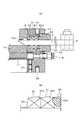
このシール部材9は、図6及び図11等の通り、ゲート板2の摺動部分をシールする横長の扁平環状(扁平小判形状)の部材であり、枠状体4に形成されゲート板2が挿通されるガイド孔46(図11参照)に固定されている。シール部材9は、シールハウジング91にグランドパッキン92が圧入されたものである。シールハウジング91は、正面断面視で先端部が丸みを帯びた略鋸歯状(波の形)等であって、かつ、側面視で横長の扁平リング帯状(扁平小判形状)の段部90(90a,90b)を備えたものである。略鋸歯状が好ましいが、竹の子形状、節形状、笠状その他の形状でも良い。段部90a,90bは複数(ここでは2個)、所定間隔を設けて備えられている。シールハウジング91は、正面視で後方に開口部を備え、そこにシール押さえ93が嵌め込まれ、内側先端部に縮径部93aを備えている。シール押さえ93の縮径部93aがグランドパッキン91の上部に食い込むようにして固定している。シール押さえ93は、側面視で横長で扁平リング帯状(扁平小判形状)とされ、複数(ここでは2個)の押え止めビス94(図11参照)で前方枠部材42に固定されている。このように、グランドパッキン92はゲート板2とシールハウジング91の内壁面とで挟まれることで、その上部は略鋸歯状の段部が形成されることとなる。シールハウジング91の詳細を説明すると、図6(b)の通り、正面視した状態において、その内壁面は、ゲート板2の軸線方向(移動方向)に対して右斜めに急峻な状態で傾斜した傾斜帯面95と、これに連続する、ゲート板2の軸線方向(移動方向)に対して緩やかに右斜め上方に傾斜した環状帯面96と、これに連続する前述の段部90aと、これに連続する、前述の環状帯面96と同様の環状帯面97と、それに連続する段部90bと、前述の環状帯面97と同様の環状帯面98とを備え、右端部(前方部分)は開口し、シール押さえ93側に段部が形成されている。そして、それらの面或いは段部は側面視で横長の扁平リング帯状(扁平小判形状)に形成されている。従来はグランドパッキンが同じ圧力で平面的にゲート板2を抑えているが、本実施形態によれば、ゲート板2とグランドパッキン92との接触において、シール圧力の粗密ができるように設定され、強く接触している個所、弱く接触している個所が微妙にできると考えられ、それらによりシール効果が高まるのである。これにより、ゲート板2が開閉される際、特に開口部3を開く場合、グランドパッキン92がゲート板2の表面に付着した粉体を拭い取ることで、粉体の移動経路から移動経路外への粉体の漏れ、即ちゲート板2に粉体が付着したまま収容ケース7へ侵入し、内部コンタミネーション、機器の故障等の不都合を防止できる。従って、シール部材9によりシール性を高めることができる。更に、図6(a)において点線で示すシールハウジング91と連通する連通孔99を形成し、後述のエアパージ119から供給される排気をシールハウジング91内へ供給することで、その内部をプラス圧としシール効果を高めることもできる。
【0022】
(シール部材10の説明)
更に、開口部3の周囲付近に平面視で四角型枠状のシール部材10を設け、開口部3が閉じられるときに存在する枠状体4とゲート板2との隙間をシールするようにしたものである。このシール部材10はラビリンスパッキンであり、下面(底面)に角型枠状の単数又は複数の凹溝10aを連続的に設けたものである。この凹溝10aに粉体が詰まることで、粉体自体がシールの役目をすることとなるマテリアルシールが形成されるのである。これにより、ゲート板2により開口部3が閉じられた場合、ゲート板2の上方に堆積した粉体或いはエアーが、ゲート板2の端縁(収容ケース7側を除く3方の端縁)と枠状体4内側との間の隙間から下方に向かって漏れることを防ぎ、粉体の移動経路内での粉体、エアーの漏れを防止できる。従って、シール部材10をラビリンスパッキンとすることで、シール性を高め、摺動抵抗を低減させることができる。更にラビリンス効果により押え止めビス94が少数で済むことで部品点数の低減と取り付け作業の容易化に寄与できる。
【0023】
(エア設備ユニット11の説明)
エア設備ユニット11は、図3に示す通り、ブラケット110等で前方枠部材42に固定され、エア導入口111、供給ポート112,113、排出ポート114,115等を備えた電磁弁ユニット116を備え、供給ポート112,113にエアシリンダ5,6のストローク速度を調整するスピードコントローラ117,118(図11参照)を備えている。又、エア導入口111、排出ポート114,115にはそれぞれワンタッチ継手55,65が取り付けられている。更に、前方枠部材42に、エアパージ119,120(図11参照)、及びエア一次配管口121(図10、図11参照)がそれぞれ配置されている。
【0024】
(電気設備ユニット13の説明)
電気設備ユニット13は、図3の通り、ブラケット130等で前方枠部材42に固定され、端子131,132を備えた結線端子ボックス133を備え、前方枠部材42に、図11の通り、電気一次配線口134、センサーリード線135等を備えたものである。結線端子ボックス133内には制御を司る制御装置136が設けられ、シリンダ5,6等の駆動制御を司る。
【0025】
(ゲートバルブ1の動作及び作用効果)
電源及びエア源(コンプレッサ等)から電源及びエアがエア設備ユニット11及び電気設備ユニット13へ供給されると、駆動処理が開始される。まず、初期状態はエアシリンダ5,6が縮んだ状態とされ、開口部3が閉じた状態とされ、粉体はゲート板2の上方に堆積しているものとする。ゲート開信号が制御装置136から電磁弁ユニット116へ供給されると、エア一次配管口121からエア導入口111へ供給され、供給ポート112,113からそれぞれ、エアシリンダ5,6のシリンダチューブ51,61内へエアが供給されるとともに、排出ポート114,115からエアが排出される。そうすると、ピストンロッド50,60が前方へ移動して伸び出しゲート板2が押出され、そして、センサースイッチ63がオンすると、センサーリード線135を介して制御装置136へ送られ、エア供給停止信号が電磁弁ユニット116へ送り出され、図3の右側端部の2点鎖線で示す位置でピストンロッド50,60が停止する。そうすると開口部3は開放され、粉体が開口部3を通過して上方から下方へ落下する。
【0026】
粉体の輸送が終了したならば、ゲート閉信号が制御装置136から電磁弁ユニット116へ供給され、電磁弁ユニット116の接続状態が切り換わり、エア一次配管口121からエア導入口111へ供給され、供給ポート112,113からそれぞれ、エアシリンダ5,6のシリンダチューブ51,61内へエアが供給されるとともに、排出ポート114,115からエアが排出される。そうすると、ピストンロッド50,60が後方へ移動して縮み、そして、センサースイッチ62がオンすると、センサーリード線135を介して制御装置136へ送られ、エア供給停止信号が電磁弁ユニット116へ送り出され、図3の実線で示す位置でピストンロッド50,60が停止する。そうすると開口部3が閉鎖されて粉体の通過が阻止され、ゲート板2の上に粉体が堆積する。
【0027】
また、ガイドレール14,15が高分子樹脂被膜により被覆処理され、シール部材10がラビリンスパッキンであるので、ゲート板2が枠状体4内を移動するときに、ゲート板2はシール部材10及びガイドレール14,15で挟みつけられつつ案内され、摺動する面の抵抗が低減されるとともに、磨耗が低減されて耐久性が向上し、更に、シール性が向上する。そして、シール部材9によりゲート板2がシールされることで、シール性が大幅に向上する。図6(a)の通り、シール部材9によってゲート板2に付着した粉体が払い落とされる前にも、ゲート板2の上部に付着した粉体が枠状体4の収容ケース7側の端縁にあるシール部材10によっても払い落とされる。また、シール部材10により隙間M(図1参照)がシールされ、シール性が大幅に向上する。
【0028】
そして、ゲートバルブ1は、エアシリンダ5,6の往復動に伴い、ゲート板2が収容ケース7内及び枠状体4内部を往復動し、開口部3を開閉するのであり、連結ロッド8は収容ケース7内のみにおいて往復動を行うものである。しかも、エアシリンダ5,6が縮むことでゲート板2を引いて開口部3を閉じ、エアシリンダ5,6が伸びることでゲート板を押して開口部3が開放されるものであるので、小型化、低コスト化に寄与できる。
【0029】
更に、エアパージ119,120から、それぞれ、パイプ17,18にエアシリンダ5,6の排気を供給し、スリット21,22からエアーを噴出することで、エアシリンダ5,6の排気を有効に利用することができ、内部にあるボルト等に堆積した食品、医薬品等の粉体に起因するコンタミネーションを防止することができHACCPを実現できる。
【0030】
図4のタイプではガイドレール14,15が無いので、開口部3がゲート板2によって閉じるときのみ、ゲート板2が突部49により支持される。ガイドレール14,15が不要となることで構造が簡素化、低コスト化に寄与する。
【0031】
次に本発明の第2実施形態のゲートバルブ201について図12〜図14を参照して説明する。第1実施形態では、収容ケース7内にエア設備ユニット11及び電気設備ユニット13が収容されているが、この第2実施形態では、収容ケース7をゲート板収容ケース207Aとし、エア設備ユニット211及び電気設備ユニット213を収容ケース207Bに収容するとともに、この収容ケース207Bを後方枠部材243側に固定し外部に露呈させるとともに、エアシリンダ205,206の端部を固定するものである。これにより第1実施形態と同様の動作、作用効果を奏するが、エア設備ユニット211及び電気設備ユニット213の点検やメンテナンスが容易となる利点がある。本実施形態は、上記構成を除き、第1実施形態と概ね同様であるので、共通する要素は200番台とし、説明は援用する。
【0032】
ゲートバルブ1,201の適用例としては、集塵機、サイクロン下の排出用、コンベア、タンク、サイロ、チェックビン下の排出用、ミキサーなどの排出用、スケール投入のゲート用、スクリューフィーダの排出用、が挙げられる。また、駆動形態としてはエアーシリンダタイプ、手動タイプ、モータータイプ等が挙げられる。形状は丸形、角形等が挙げられる。
【0033】
本発明は、上述の実施の形態又は実施形態に限定されるものではなく、本発明の技術的思想を逸脱しない範囲に於て、改変等を加えることが出来るものであり、それらの改変、均等物等も本発明の技術的範囲に含まれることとなる。一例として、上記説明では、ゲート板2を駆動させるのに、エア圧を利用したエアシリンダ5,6を使用したが、エアシリンダ5,6以外に、油圧、水圧等を利用したシリンダ、モータ等が考えられ、その他に、機械的に棒を左右動させることのできる手動式の装置等にしても構わない。しかし、エアシリンダ5,6とした方が制御は簡単であり、好ましい。
【0034】
【発明の効果】
請求項1記載の発明によれば、エアシリンダの排気をシールハウジングに導入することで、排気圧力によって、シール性が一層高められるとともに、排気を有効利用することができる。
【図面の簡単な説明】
【図1】本発明の第1実施形態の粉体用スライド式ゲートバルブを表した平面図である。
【図2】(a)は同正面図、(b)は同底面図である。
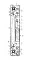
【図3】同内部構造を示す平面図である。
【図4】(a)は同変更形態の部分側面図、(b)は同変更形態の側面断面図である。
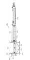
【図5】図3のV−V線に沿って切断した断面図である。
【図6】(a)は図5の部分拡大断面図、(b)はシールハウジングの断面図である。
【図7】図3のVII−VII線に沿って切断した断面図である。
【図8】図5のVIII−VIII線に沿って切断した断面図である。
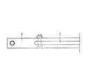
【図9】第1実施形態の粉体用スライド式ゲートバルブの連結ロッド及びゲート板の右側面図である。
【図10】同内部構造を示す正面図である。
【図11】図3のXI−XI線に沿って切断した断面図である。
【図12】本発明第2実施形態の粉体用スライド式ゲートバルブの内部構造を表した平面図である。
【図13】同内部構造を表した正面図である。
【図14】図12のXIV−XIV線に沿って切断した断面図である。
【図15】従来の粉粒体用スライド式ゲートバルブの内部構造を示す平面図である。
【図16】同内部構造を示す正面図である。
【符号の説明】
1…粉体用スライド式ゲートバルブ、2…ゲート板、3…開口部、
4…枠状体、40,41…側枠部材、42…前方枠部材、43…後方枠部材、
46…ガイド孔、47,48…連結孔、9…シール部材、90…段部、
91…シールハウジング、92…グランドパッキン、93a…拡径部、
93…シール押さえ、94…押え止めビス、95…傾斜帯面、
96,97…環状帯面、10…シール部材、14,15…ガイドレール、
16…開口溝、17,18…パイプ、21,22…スリット[0001]
BACKGROUND OF THE INVENTION
The present invention relates to a sliding gate valve for a granular material that opens and closes a granular material transport path for conveying the granular material with a gate, and more particularly to a seal structure thereof.
[0002]
[Prior art]
Conventionally, a slide
Here, the square type is for square rectangular outlets, and is applicable to discharging powder particles such as conveyors and tanks. The round type is for circular outlets, silos, check The aspect applied for discharge of granular materials, such as under a bottle, is illustrated. The structure is simple and maintenance is easy, and the sealing performance is improved by the sealing method according to the application.
[0003]
However, although the gap between the
[0004]
[Problems to be solved by the invention]
Therefore, the claim1According to the invention described above, the leakage of the granular material in the moving path of the granular material when the gate plate is closed, or the powder from the moving path of the granular material when the gate plate is opened and closed to the outside of the moving path. The object is to prevent leakage of the granules.
[0005]
[Means for Solving the Problems]
In view of the above-mentioned problems, a first aspect of the present invention provides a frame-shaped body having an opening, an actuator disposed in the frame-shaped body, a storage case connected to the frame-shaped body, and a powder by the actuator. A gate plate that opens and closes the opening by performing a sliding motion perpendicular to the direction of the moving path of the granules, and a through hole formed in the storage case side region of the frame-like body.The seal is pressed into the sealed housing.By sealing between the frame and the gate plate,Prevent leakage from the movement path of the granular material to the outside of the movement pathRuAnd a support member for supporting the gate plate,The actuator is an air cylinder, and the exhaust of the air cylinder is introduced into the seal housing.It is the slide type gate valve for granular materials characterized by becoming.As a result, the pressure in the seal housing is increased by the exhaust gas discharged when the gate plate is driven by the air cylinder, and the leakage of the granular material from the moving path of the granular material to the outside of the moving path is further effectively prevented. Can be improved. There are various structures for the seal member, which can be appropriately selected.Here, the accommodation case accommodates the gate plate when the gate plate is opened or closed, and may accommodate an electrical component, a pneumatic component, or the like. The support member corresponds to one that supports when the gate plate is closed, or a guide rail when the gate plate opens and closes..
[0010]
in frontThe support member is a guide rail, the guide rail that guides the gate plate while supporting the gate plate from below is provided in the frame-like body in the direction of the sliding movement, and when the opening is opened and closed, the gate plate It was made to slide while being pinched between the second seal member and the guide member.Is preferred. As a result, the above-mentioned problems can be suitably achieved, and the gate plate is prevented from being bent by the load of the granular material deposited on the upper portion of the gate plate when the gate plate is closed, and the strength and durability are improved. be able to. The sliding movement of a relatively large gate plate can be made smooth.
[0011]
in frontThe supporting member is two or more protrusions provided in the inner region of the frame-like body, and supports the gate plate from below when the gate plate closes the opening.Is preferred. Thereby, the above problem can be suitably achieved, and by supporting the gate plate when the gate plate is closed, the gate plate is prevented from being bent due to the load of the granular material deposited on the gate plate, Strength and durability can be improved.
[0012]
DETAILED DESCRIPTION OF THE INVENTION
Hereinafter, a powder sliding gate valve 1 (hereinafter simply referred to as a gate valve 1) according to a first embodiment of the present invention will be described with reference to FIGS. As shown in FIGS. 1 to 3, the
[0013]
(Description of frame 4)
The frame-
[0014]
Next, a plurality of connecting
[0015]
That is, the
[0016]
15 and 16 has a structure in which the
[0017]
In order to support the
[0018]
(Description of
The
[0019]
Sensor switches 62 and 63 (see FIGS. 1 and 3) are formed at both ends of the
[0020]
(Description of the housing case 7)
The
[0021]
(Description of seal member 9)
As shown in FIGS. 6 and 11, the
[0022]
(Description of seal member 10)
Furthermore, a rectangular frame-shaped sealing
[0023]
(Description of air equipment unit 11)
As shown in FIG. 3, the
[0024]
(Description of electrical equipment unit 13)
As shown in FIG. 3, the
[0025]
(Operation and effect of gate valve 1)
When power and air are supplied from the power and air source (compressor or the like) to the
[0026]
When the transportation of the powder is completed, a gate closing signal is supplied from the
[0027]
Further, since the guide rails 14 and 15 are coated with a polymer resin film and the
[0028]
The
[0029]
Further, exhaust from the
[0030]
In the type of FIG. 4, since there are no
[0031]
Next, a
[0032]
Examples of application of the gate valves 1,201 include dust collectors, discharge under a cyclone, conveyor, tank, silo, discharge under a check bottle, discharge for a mixer, etc., gate for scale input, screw feeder discharge, Is mentioned. Moreover, as a drive form, an air cylinder type, a manual type, a motor type, etc. are mentioned. Examples of the shape include a round shape and a square shape.
[0033]
The present invention is not limited to the above-described embodiments or embodiments, and modifications and the like can be made without departing from the technical idea of the present invention. Things and the like are also included in the technical scope of the present invention. As an example, in the above description, the
[0034]
【The invention's effect】
According to the first aspect of the present invention, by introducing the exhaust of the air cylinder into the seal housing, the sealing performance is further enhanced by the exhaust pressure, and the exhaust can be used effectively..
[Brief description of the drawings]
FIG. 1 is a plan view showing a powder-type sliding gate valve according to a first embodiment of the present invention.
2A is a front view thereof, and FIG. 2B is a bottom view thereof.
FIG. 3 is a plan view showing the internal structure.
4A is a partial side view of the modified embodiment, and FIG. 4B is a side cross-sectional view of the modified embodiment.
5 is a cross-sectional view taken along line VV in FIG.
6A is a partially enlarged cross-sectional view of FIG. 5, and FIG. 6B is a cross-sectional view of a seal housing.
7 is a cross-sectional view taken along line VII-VII in FIG.
8 is a cross-sectional view taken along line VIII-VIII in FIG.
FIG. 9 is a right side view of a connecting rod and a gate plate of the sliding gate valve for powder of the first embodiment.
FIG. 10 is a front view showing the internal structure.
11 is a cross-sectional view taken along line XI-XI in FIG.
FIG. 12 is a plan view showing the internal structure of a sliding gate valve for powder according to a second embodiment of the present invention.
FIG. 13 is a front view showing the internal structure.
14 is a cross-sectional view taken along line XIV-XIV in FIG.
FIG. 15 is a plan view showing the internal structure of a conventional sliding gate valve for granular material.
FIG. 16 is a front view showing the internal structure.
[Explanation of symbols]
DESCRIPTION OF
4 ... Frame-like body, 40, 41 ... Side frame member, 42 ... Front frame member, 43 ... Rear frame member,
46 ... Guide hole, 47,48 ... Connection hole, 9 ... Seal member, 90 ... Step part,
91 ... Seal housing, 92 ... Gland packing, 93a ... Diameter expansion part,
93: Seal presser, 94: Presser screw, 95 ... Inclined belt surface,
96, 97 ... annular belt surface, 10 ... sealing member, 14, 15 ... guide rail,
16 ... Open groove, 17, 18 ... Pipe, 21,22 ... Slit
Claims (1)
Translated fromJapanese該枠状体に配置されたアクチュエータと、
前記枠状体と接続された収容ケースと、
前記アクチュエータによって粉粒体の移動経路の方向に直交してスライド運動を行うことで前記開口部を開閉するゲート板と、
前記枠状体の前記収容ケース側の領域に形成された貫通孔に設けられたシールハウジングにパッキンが圧入され、前記枠状体と前記ゲート板との間をシールすることにより、前記粉粒体の移動経路から移動経路外への漏れを防止するシール部材と、
前記ゲート板を支持する支持部材と、を備え、
前記アクチュエータがエアシリンダであり、
前記シールハウジングに前記エアシリンダの排気を導入してなることを特徴とする粉粒体用スライド式ゲートバルブ。A frame with an opening;
An actuator disposed in the frame,
A storage case connected to the frame,
A gate plate that opens and closes the opening by performing a sliding motion perpendicular to the direction of the moving path of the granular material by the actuator;
A packing is press-fitted into a seal housing provided in a through-hole formed in a region on the housing case side of the frame-like body, and seals between the frame-like body and the gate plate. A seal member for preventing leakage from the movement path to the outside of the movement path;
A support member for supporting the gate plate,
The actuator is an air cylinder;
A sliding gate valve for a granular material, wherein the air cylinder exhaust is introduced into the seal housing.
Priority Applications (5)
| Application Number | Priority Date | Filing Date | Title |
|---|---|---|---|
| JP2000046105AJP4598219B2 (en) | 2000-02-23 | 2000-02-23 | Sliding gate valve for granular materials |
| DE10195712TDE10195712T5 (en) | 2000-02-23 | 2001-02-23 | Gate valve for powder and granules |
| US10/204,753US6817593B2 (en) | 2000-02-23 | 2001-02-23 | Slide gate valve for powder and granular material |
| AU2001234140AAU2001234140A1 (en) | 2000-02-23 | 2001-02-23 | Slide gate valve for powder and granular material |
| PCT/JP2001/001335WO2001063155A1 (en) | 2000-02-23 | 2001-02-23 | Slide gate valve for powder and granular material |
Applications Claiming Priority (1)
| Application Number | Priority Date | Filing Date | Title |
|---|---|---|---|
| JP2000046105AJP4598219B2 (en) | 2000-02-23 | 2000-02-23 | Sliding gate valve for granular materials |
Publications (2)
| Publication Number | Publication Date |
|---|---|
| JP2001235039A JP2001235039A (en) | 2001-08-31 |
| JP4598219B2true JP4598219B2 (en) | 2010-12-15 |
Family
ID=18568583
Family Applications (1)
| Application Number | Title | Priority Date | Filing Date |
|---|---|---|---|
| JP2000046105AExpired - LifetimeJP4598219B2 (en) | 2000-02-23 | 2000-02-23 | Sliding gate valve for granular materials |
Country Status (5)
| Country | Link |
|---|---|
| US (1) | US6817593B2 (en) |
| JP (1) | JP4598219B2 (en) |
| AU (1) | AU2001234140A1 (en) |
| DE (1) | DE10195712T5 (en) |
| WO (1) | WO2001063155A1 (en) |
Families Citing this family (15)
| Publication number | Priority date | Publication date | Assignee | Title |
|---|---|---|---|---|
| US7614429B2 (en)* | 2005-05-18 | 2009-11-10 | Symyx Solutions, Inc. | Apparatus and methods for storing and dispensing solid material |
| US7771150B2 (en)* | 2005-08-26 | 2010-08-10 | Jusung Engineering Co., Ltd. | Gate valve and substrate-treating apparatus including the same |
| JP5059489B2 (en)* | 2007-06-04 | 2012-10-24 | 株式会社ツカサ | Granule passage opening and closing device |
| US20100127022A1 (en)* | 2008-11-21 | 2010-05-27 | Symyx Technologies, Inc. | Dispensing valve |
| DE102009056686B4 (en)* | 2009-12-02 | 2012-01-12 | Prometal Rct Gmbh | Construction area limitation of a rapid prototyping facility |
| US8641014B2 (en) | 2010-09-10 | 2014-02-04 | Applied Materials, Inc. | Gate valve |
| JP5793459B2 (en)* | 2012-03-30 | 2015-10-14 | 新日鐵住金ステンレス株式会社 | Heat-resistant ferritic stainless steel cold-rolled steel sheet excellent in workability, ferritic stainless hot-rolled steel sheet for cold-rolled material, and production method thereof |
| CN107407419B (en)* | 2015-04-10 | 2020-08-25 | 日本皮拉工业株式会社 | Gland seal and method of manufacturing gland seal |
| US10408350B2 (en) | 2015-04-10 | 2019-09-10 | Nippon Pillar Packing Co., Ltd. | Gland packing and gland packing manufacturing method |
| US10167961B2 (en) | 2016-04-19 | 2019-01-01 | Emerson Vulcan Holding Llc | Port gate supports for a gate valve |
| US10274089B2 (en) | 2016-04-19 | 2019-04-30 | Emerson Vulcan Holding Llc | Gate supports for a gate valve |
| CN107246482B (en)* | 2017-02-10 | 2023-04-07 | 上海市机电设计研究院有限公司 | Quick opening and closing gate valve device for stokehole charging pipe of biomass power plant |
| WO2019236880A1 (en) | 2018-06-06 | 2019-12-12 | Dezurik, Inc. | Knife gate valve with dead-end service |
| WO2021012177A1 (en)* | 2019-07-23 | 2021-01-28 | 深圳市西啡科技有限公司 | Dropping mechanism, storage apparatus, and self-service vending machine |
| CN119617130A (en)* | 2024-12-16 | 2025-03-14 | 中国船舶集团有限公司第七〇三研究所 | A double-layer plate-type rigid self-sealing high-temperature heat source dissipation and propagation isolation device |
Family Cites Families (21)
| Publication number | Priority date | Publication date | Assignee | Title |
|---|---|---|---|---|
| US3559948A (en)* | 1968-09-19 | 1971-02-02 | M & J Valve Co | Gate valve construction |
| US3625480A (en)* | 1970-03-17 | 1971-12-07 | Aloyco Inc | Temperature compensated preloaded seal |
| US4334550A (en)* | 1975-12-10 | 1982-06-15 | Mosser Industries, Inc. | Sealing means for sliding gate valve |
| US4356838A (en)* | 1980-10-16 | 1982-11-02 | Etablissements Trouvay & Cauvin | Guillotine valve |
| US4415139A (en)* | 1981-08-03 | 1983-11-15 | Eastman Kodak Company | Automatic sliding gate valve |
| JPS6012762U (en)* | 1983-07-05 | 1985-01-28 | 株式會社栗本鐵工所 | Elastic seat ring for butterfly valve |
| US4512359A (en)* | 1984-04-13 | 1985-04-23 | Daniel Industries, Inc. | Valve mechanism with replaceable seal rings |
| JPS6342978U (en)* | 1986-09-05 | 1988-03-22 | ||
| US4693447A (en)* | 1986-09-16 | 1987-09-15 | Kaiser Aerospace & Electronics Corporation | Motorized gate valve for a waste disposal system |
| US4798365A (en)* | 1987-05-20 | 1989-01-17 | Alphabet, Inc. | Throttling gasket insert for use with knife gate valve |
| JPH084846Y2 (en)* | 1989-03-23 | 1996-02-14 | 株式会社クボタ | Hopper structure of thresher |
| US5020776A (en)* | 1990-06-04 | 1991-06-04 | Warman International, Inc. | Split seat gate valve |
| WO1993000536A1 (en)* | 1991-06-24 | 1993-01-07 | Walter Allen Clifford | Further improved gate valves |
| JPH0527444U (en)* | 1991-09-24 | 1993-04-09 | エヌオーケー株式会社 | valve |
| JP2532216Y2 (en)* | 1992-02-05 | 1997-04-09 | コスモ工機株式会社 | Gate valve |
| JP3154824B2 (en)* | 1992-08-07 | 2001-04-09 | 株式会社クボタ | High temperature slide valve |
| US5413140A (en)* | 1994-06-29 | 1995-05-09 | Warman International Ltd. | Spring-assisted split seat gate valve |
| JP2958267B2 (en)* | 1996-05-07 | 1999-10-06 | 入江工研株式会社 | Non-sliding vacuum gate valve |
| JPH11201299A (en) | 1998-01-19 | 1999-07-27 | Suiken Technology:Kk | Sluice valve |
| US6206376B1 (en)* | 1998-12-08 | 2001-03-27 | Thomas A. Hartman | Apparatus and method of sealing a valve against increasing fluid pressure |
| JP4321937B2 (en)* | 2000-02-17 | 2009-08-26 | ツカサ工業株式会社 | Sliding gate valve for granular materials |
- 2000
- 2000-02-23JPJP2000046105Apatent/JP4598219B2/ennot_activeExpired - Lifetime
- 2001
- 2001-02-23USUS10/204,753patent/US6817593B2/ennot_activeExpired - Lifetime
- 2001-02-23WOPCT/JP2001/001335patent/WO2001063155A1/enactiveApplication Filing
- 2001-02-23AUAU2001234140Apatent/AU2001234140A1/ennot_activeAbandoned
- 2001-02-23DEDE10195712Tpatent/DE10195712T5/ennot_activeWithdrawn
Also Published As
| Publication number | Publication date |
|---|---|
| US20030155543A1 (en) | 2003-08-21 |
| WO2001063155A1 (en) | 2001-08-30 |
| AU2001234140A1 (en) | 2001-09-03 |
| JP2001235039A (en) | 2001-08-31 |
| US6817593B2 (en) | 2004-11-16 |
| DE10195712T5 (en) | 2004-07-01 |
Similar Documents
| Publication | Publication Date | Title |
|---|---|---|
| JP4598219B2 (en) | Sliding gate valve for granular materials | |
| JP4330242B2 (en) | Sliding gate valve for granular materials | |
| US6283680B1 (en) | Device for pneumatic transport of material such as concrete | |
| JP4321937B2 (en) | Sliding gate valve for granular materials | |
| US20110155257A1 (en) | Method and arrangement in a pneumatic material conveying system | |
| KR940011532B1 (en) | Vessel for anaerobic fermentation | |
| CN1195664C (en) | Method and apparatus for treatment of blowable thermal insulation material | |
| CN87105329A (en) | device for transporting materials | |
| CN119330080B (en) | Powder conveying device | |
| CN2704568Y (en) | Vacuum conveyor | |
| US5665225A (en) | Separating device | |
| KR100759347B1 (en) | Fully-operated vacuum injection machine cylinder gas discharge device by vertical slide and 2 gas discharge | |
| CN218012160U (en) | Horizontal mixer with self-cleaning function | |
| CN217626513U (en) | Air draft dust removal structure of movable discharging car | |
| JP2004142859A (en) | Conveyor | |
| CN212531107U (en) | Novel lock wind vibration feeding conveyor | |
| US4220425A (en) | Method and apparatus for assisting pneumatic conveyors utilizing vacuum | |
| KR910700186A (en) | Feeder for fine materials | |
| FR2831848A1 (en) | Building site cement/plaster mixer has inlet grid and dust cover | |
| CN2296873Y (en) | Material receiving device for air-cushion belt conveyer | |
| CN210527623U (en) | Chain tensioning device of pipe chain conveyor | |
| CN221374517U (en) | Gate and feeding system | |
| CN213386716U (en) | Vacuum feeding device is used in production of compound leavening agent | |
| CN217478584U (en) | Telescopic discharge gate structure | |
| CN217866934U (en) | A kind of three-way structure of feed conveying pipeline |
Legal Events
| Date | Code | Title | Description |
|---|---|---|---|
| A621 | Written request for application examination | Free format text:JAPANESE INTERMEDIATE CODE: A621 Effective date:20070130 | |
| A131 | Notification of reasons for refusal | Free format text:JAPANESE INTERMEDIATE CODE: A131 Effective date:20091106 | |
| A521 | Request for written amendment filed | Free format text:JAPANESE INTERMEDIATE CODE: A523 Effective date:20100102 | |
| A131 | Notification of reasons for refusal | Free format text:JAPANESE INTERMEDIATE CODE: A131 Effective date:20100616 | |
| A521 | Request for written amendment filed | Free format text:JAPANESE INTERMEDIATE CODE: A523 Effective date:20100803 | |
| TRDD | Decision of grant or rejection written | ||
| A01 | Written decision to grant a patent or to grant a registration (utility model) | Free format text:JAPANESE INTERMEDIATE CODE: A01 Effective date:20100915 | |
| A01 | Written decision to grant a patent or to grant a registration (utility model) | Free format text:JAPANESE INTERMEDIATE CODE: A01 | |
| A61 | First payment of annual fees (during grant procedure) | Free format text:JAPANESE INTERMEDIATE CODE: A61 Effective date:20100924 | |
| R150 | Certificate of patent or registration of utility model | Ref document number:4598219 Country of ref document:JP Free format text:JAPANESE INTERMEDIATE CODE: R150 Free format text:JAPANESE INTERMEDIATE CODE: R150 | |
| FPAY | Renewal fee payment (event date is renewal date of database) | Free format text:PAYMENT UNTIL: 20131001 Year of fee payment:3 | |
| R250 | Receipt of annual fees | Free format text:JAPANESE INTERMEDIATE CODE: R250 | |
| R250 | Receipt of annual fees | Free format text:JAPANESE INTERMEDIATE CODE: R250 | |
| R250 | Receipt of annual fees | Free format text:JAPANESE INTERMEDIATE CODE: R250 | |
| EXPY | Cancellation because of completion of term |