JP4598181B2 - Endoscopic clip device - Google Patents
Endoscopic clip deviceDownload PDFInfo
- Publication number
- JP4598181B2 JP4598181B2JP2005000334AJP2005000334AJP4598181B2JP 4598181 B2JP4598181 B2JP 4598181B2JP 2005000334 AJP2005000334 AJP 2005000334AJP 2005000334 AJP2005000334 AJP 2005000334AJP 4598181 B2JP4598181 B2JP 4598181B2
- Authority
- JP
- Japan
- Prior art keywords
- clip
- endoscope
- clips
- sheath
- tip
- Prior art date
- Legal status (The legal status is an assumption and is not a legal conclusion. Google has not performed a legal analysis and makes no representation as to the accuracy of the status listed.)
- Expired - Fee Related
Links
Images


Classifications
- A—HUMAN NECESSITIES
- A61—MEDICAL OR VETERINARY SCIENCE; HYGIENE
- A61B—DIAGNOSIS; SURGERY; IDENTIFICATION
- A61B17/00—Surgical instruments, devices or methods
- A61B17/12—Surgical instruments, devices or methods for ligaturing or otherwise compressing tubular parts of the body, e.g. blood vessels or umbilical cord
- A61B17/128—Surgical instruments, devices or methods for ligaturing or otherwise compressing tubular parts of the body, e.g. blood vessels or umbilical cord for applying or removing clamps or clips
- A61B17/1285—Surgical instruments, devices or methods for ligaturing or otherwise compressing tubular parts of the body, e.g. blood vessels or umbilical cord for applying or removing clamps or clips for minimally invasive surgery
- A—HUMAN NECESSITIES
- A61—MEDICAL OR VETERINARY SCIENCE; HYGIENE
- A61B—DIAGNOSIS; SURGERY; IDENTIFICATION
- A61B17/00—Surgical instruments, devices or methods
- A61B17/08—Wound clamps or clips, i.e. not or only partly penetrating the tissue ; Devices for bringing together the edges of a wound
- A61B17/083—Clips, e.g. resilient
- A—HUMAN NECESSITIES
- A61—MEDICAL OR VETERINARY SCIENCE; HYGIENE
- A61B—DIAGNOSIS; SURGERY; IDENTIFICATION
- A61B17/00—Surgical instruments, devices or methods
- A61B17/12—Surgical instruments, devices or methods for ligaturing or otherwise compressing tubular parts of the body, e.g. blood vessels or umbilical cord
- A61B17/122—Clamps or clips, e.g. for the umbilical cord
- A61B17/1227—Spring clips
Landscapes
- Health & Medical Sciences (AREA)
- Surgery (AREA)
- Life Sciences & Earth Sciences (AREA)
- Heart & Thoracic Surgery (AREA)
- Nuclear Medicine, Radiotherapy & Molecular Imaging (AREA)
- Vascular Medicine (AREA)
- Engineering & Computer Science (AREA)
- Biomedical Technology (AREA)
- Reproductive Health (AREA)
- Medical Informatics (AREA)
- Molecular Biology (AREA)
- Animal Behavior & Ethology (AREA)
- General Health & Medical Sciences (AREA)
- Public Health (AREA)
- Veterinary Medicine (AREA)
- Surgical Instruments (AREA)
Description
Translated fromJapaneseこの発明は、生体内等において止血やマーキング等を行うために内視鏡の処置具挿通チャンネルに通して使用される内視鏡用クリップ装置に関する。 The present invention relates to an endoscope clip device that is used through a treatment instrument insertion channel of an endoscope in order to perform hemostasis or marking in a living body or the like.
管腔臓器内等において止血やマーキング等を行うためのクリッピング処置が、クリップ装置を内視鏡の処置具挿通チャンネルに通して行われているが、クリッピング処置を一回行う毎にクリップ装置を内視鏡の処置具挿通チャンネルから引き出してクリップを装填し直すのでは操作があまりに煩雑になってしまう。 Clipping treatment for hemostasis and marking in a luminal organ etc. is performed by passing the clip device through the treatment instrument insertion channel of the endoscope. If it is pulled out from the treatment instrument insertion channel of the endoscope and reloaded with a clip, the operation becomes too complicated.
そこで、内視鏡の処置具挿通チャンネルに挿脱されるシースの先端内に複数のクリップを各々窄まった状態に直列に配置し、シース内に軸線方向に進退自在に配置された操作ワイヤで複数のクリップをシースの先端から順次押し出して、各クリップを一旦開いた後に閉じることができるように構成された内視鏡用クリップ装置が案出されている(例えば、特許文献1)。
しかし、特許文献1に記載されているような従来の内視鏡用クリップ装置においては、シースの先端内に配置される複数のクリップが操作ワイヤの先端と個別に結紮ワイヤ等で連結されているので、後方に位置するクリップになればなるほど多くの結紮ワイヤと干渉してしまう配置状態になり、構造的に雑然としたものになって円滑に動作しない場合が少なくなかった。 However, in the conventional endoscope clip device described in
そこで本発明は、シースの先端内に複数のクリップを整然かつ簡潔に配置することができて、連続的なクリッピング処置を円滑な動作で行うことができる内視鏡用クリップ装置を提供することを目的とする。 Accordingly, the present invention provides an endoscopic clip device in which a plurality of clips can be arranged in an orderly and concise manner within the distal end of a sheath, and a continuous clipping procedure can be performed with a smooth operation. Objective.
上記の目的を達成するため、本発明の内視鏡用クリップ装置は、嘴状に開閉させることができる複数のクリップが、内視鏡の処置具挿通チャンネルに挿脱されるシースの先端内に各々窄まった状態で直列に配置されて、シース内に軸線方向に進退自在に配置された操作ワイヤにより複数のクリップがシースの先端から順次押し出されて、各クリップが一旦開いた後に閉じることができるように構成された内視鏡用クリップ装置において、各クリップの先端部分に各クリップの閉じ方向に向かって折れ曲がった先端爪部が形成されると共に、先端爪部を差し込み係合自在な連結孔が、嘴状に開閉動作をするクリップの開閉動作面に対し直交する向きに各クリップの後端部分に形成され、隣り合うクリップの先端爪部と連結孔とを係合させることにより、複数のクリップがシース内において軸線周り方向に90°ずつ交互に向きを変えて直接連結されるようにしたものである。In order to achieve the above object, the clip device for an endoscope according to the present invention has a plurality of clips that can be opened and closed in a hook shape in the distal end of a sheath that is inserted into and removed from the treatment instrument insertion channel of the endoscope. A plurality of clips are sequentially pushed out from the distal end of the sheath by an operation wire that is arranged in series in a constricted state and can be moved forward and backward in the axial direction in the sheath, and each clip can be closed once opened. In the endoscope clip device configured to be able to be formed, a distal end claw portion that is bent toward the closing direction of each clip is formed at the distal end portion of each clip, and the distal end claw portion can be inserted and engaged freely.but it is formed on the rear end portion of each clipin the direction orthogonal to the opening and closing surface of the clip to the opening and closing operation beak, to engage the a tip claw portion of the adjacent clip connecting hole More, in which a plurality of clips has to be connected directly with different orientations alternately 90 ° around the axis direction within the sheath.
なお、先端爪部が連結孔内に緩く差し込まれて回動自在な状態に係合していてもよく、クリップを閉じたときに、そのクリップの先端に形成されている一対の先端爪部どうしが食い違うように構成されていてもよい。 The tip claw portion may be loosely inserted into the coupling hole and engaged in a freely rotatable state. When the clip is closed, the pair of tip claw portions formed at the tip of the clip May be configured to conflict.
また、各クリップの先端爪部とその前側に隣接するクリップの連結孔とが係合して二つのクリップが連結された状態のときに、前側のクリップの後端面に緩く当接する当接片が各クリップに設けられていてもよい。 In addition, when the front end claw portion of each clip and the connection hole of the clip adjacent to the front side are engaged and the two clips are connected, a contact piece loosely contacting the rear end surface of the front side clip is provided. Each clip may be provided.
また、各クリップが、一枚のバネ性のある板材を折り曲げて形成されていてもよく、その場合に、連結孔が板材を環状に曲げて形成されていてもよく、当接片が板材をクリップの側面位置で折り曲げて形成されていてもよい。 In addition, each clip may be formed by bending a single spring-like plate material, and in that case, the connection hole may be formed by bending the plate material in an annular shape, and the contact piece may be formed by bending the plate material. You may bend and form in the side surface position of a clip.
本発明によれば、隣り合うクリップの先端爪部と連結孔とを係合させることにより複数のクリップが直接連結されるので、連結のための別部材を全く必要とせず、シースの先端内に複数のクリップを整然かつ簡潔に配置することができて連続的なクリッピング処置を円滑な動作で行うことができ、複数のクリップがシース内において軸線周り方向に90°ずつ交互に向きを変えて連結されるので、内視鏡の湾曲部内を通過する際等に屈曲させられる状態になってもそのカーブに沿ってクリップ装置が屈曲して湾曲部内等をスムーズに通過することができる。 According to the present invention, since the plurality of clips are directly connected by engaging the front end claw portion of the adjacent clip and the connection hole, no separate member for connection is required, and the distal end of the sheath Multiple clips can be arranged in an orderly and concise manner, allowing continuous clipping procedures to be performed smoothly, and multiple clips connected to each other by turning around the axis 90 degrees alternately in the sheath. As a result, even when it is bent when passing through the bending portion of the endoscope, the clip device can be bent along the curve and smoothly pass through the bending portion.
嘴状に開閉させることができる複数のクリップが、内視鏡の処置具挿通チャンネルに挿脱されるシースの先端内に各々窄まった状態で直列に配置されて、シース内に軸線方向に進退自在に配置された操作ワイヤにより複数のクリップがシースの先端から順次押し出されて、各クリップが一旦開いた後に閉じることができるように構成された内視鏡用クリップ装置において、各クリップの先端部分に各クリップの閉じ方向に向かって折れ曲がった先端爪部が形成されると共に、先端爪部を差し込み係合自在な連結孔が、嘴状に開閉動作をするクリップの開閉動作面に対し直交する向きに各クリップの後端部分に形成され、隣り合うクリップの先端爪部と連結孔とを係合させることにより、複数のクリップがシース内において軸線周り方向に90°ずつ交互に向きを変えて直接連結されるようにする。A plurality of clips that can be opened and closed in a bowl shape are arranged in series in a state where each clip is constricted in the distal end of the sheath inserted into and removed from the treatment instrument insertion channel of the endoscope, and advances and retracts in the axial direction in the sheath. In an endoscopic clip device configured such that a plurality of clips are sequentially pushed out from the distal end of a sheath by an operation wire that is freely arranged, and each clip can be closed once opened. Thefront end claw part bent toward the closing direction of each clip is formed, and the connecting hole intowhich the front end claw part can be inserted and engaged isperpendicular to the opening and closing operation surface of the clip that opens and closes like a bowl. 90 formed at the rear end portion of each clip, by engaging the coupling with the distal end claw portion of the adjacent clip holes, about the axial line direction a plurality of clips in the sheath Each to be connected directly to change the direction alternately.
図面を参照して本発明の実施例を説明する。
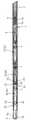
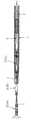
図1は内視鏡用クリップ装置の先端付近の側面断面図、図2は平面断面図であり、1は、図示されていない内視鏡の処置具挿通チャンネルに挿脱される可撓性のシースである。シース1は、例えばステンレス鋼線を一定の径で密着巻きしたコイルパイプ1aに四フッ化エチレン樹脂チューブ1bを外装して形成されており、その直径は2〜3mm程度、長さは1〜2m程度である。Embodiments of the present invention will be described with reference to the drawings.
FIG. 1 is a side sectional view of the vicinity of the distal end of an endoscope clip device, FIG. 2 is a plan sectional view, and 1 is a flexible member that is inserted into and removed from a treatment instrument insertion channel of an endoscope (not shown). Sheath. The
シース1内には、基端側から軸線方向に進退操作自在な操作ワイヤ2が挿通配置されており、シース1の図示されていない基端側に連結された操作部からの操作により操作ワイヤ2が進退操作される。 An
そのようなシース1の先端部分内には、嘴状に開閉させることができる複数の(この実施例では3個の)クリップ3(3A,3B,3C)が各々窄まった状態で直列に配置されており、操作ワイヤ2により複数のクリップ3をシース1の先端から順次押し出して、クリップ3を一旦開いた後に閉じることができるように構成されている。 A plurality of (three in this embodiment) clips 3 (3A, 3B, 3C) that can be opened and closed in a hook shape are arranged in series in the distal end portion of such a
操作ワイヤ2の先端には、最後端のクリップ3Cと係脱可能に連結された連結部材5が連結パイプ6を介して固定的に連結されている。また、シース1の最先端部分には金属製又はプラスチック製の筒状の先端チップ7が固定的に取り付けられている。 A connecting
各クリップ3は、外力が作用していない状態が図3に単体で示されるように、例えばステンレス鋼板等のようなバネ性のある一枚の板材を後端側で曲げ戻して形成されていて、その後寄りの部分31では、曲げ戻されて二枚になっている板材の板面どうしが密接している。 Each
そして各クリップ3は、後寄りの部分31と中間部分32との間で外方に折り曲げられて中間部分32は嘴状に前方に向かって広がり、中間部分32と先寄りの部分33との間でさらに外方に向かって大きく広がっている。なお、後寄りの部分31と中間部分32は後述する締め環4内に通る程度に細幅に形成され、先寄りの部分33は締め環4内に通らない程度に幅広に形成されている。 Each
クリップ3の最先端部分(嘴状に開閉する最先端部分の双方)にはクリップ3の閉じ方向に向かって突出する一対の先端爪部34が折り曲げ形成されている。また、クリップ3の後端曲げ戻し部分は環状に膨らんだ形状に形成されていて、それによって先端爪部34を差し込み係合自在な連結孔36が形成されている。その結果、連結孔36は、図5等に示されるように、嘴状に開閉動作をするクリップ3の開閉動作面に対し直交する向きに形成されている。A pair of front-
各クリップ3の先寄りの部分33の先端に形成された一対の先端爪部34は、クリップ3を閉じきった状態にしたときに互いにぶつかり合わずに食い違うように、折り曲げ位置を僅かに前後方向にずらして形成されており、連結孔36は、そのような一対の先端爪部34が緩く通されて内部で回動することができる程度の大きさに形成されている。 The pair of
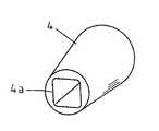
図4は、クリップ3を強制的に閉じ状態にするための締め環4を示しており、締め環4は、外面が円形の断面形状で先側に次第に径が小さくなるテーパ状に形成され、内面4aはそこに通されるクリップ3の断面形状に合わせて矩形状の断面形状に形成されている。 FIG. 4 shows a
図5と図6は、最先端のクリップ3Aと2番目のクリップ3Bとが連結された状態の側面断面図と平面断面図であり、図示されていないシース1内に収容されることにより閉じた状態になっている2番目のクリップ3Bの一対の先端爪部34が最先端のクリップ3Aの連結孔36内に緩く差し込まれて、最先端のクリップ3Aと2番目のクリップ3Bとが直接連結された状態になっている。このとき、一対の先端爪部34が食い違った状態に噛み合っているので、連結孔36と安定した状態に係合する。 FIGS. 5 and 6 are a side sectional view and a plan sectional view showing a state in which the most
そのような連結構造により、最先端のクリップ3Aと2番目のクリップ3Bとはシース1内においてシース1の軸線周り方向に90°向きを変えて連結され、3番目のクリップ3Cは、さらに2番目のクリップ3Bに対して90°向きを変えて連結されて最先端のクリップ3Aと180°反転した向き(又は最先端のクリップ3Aと同じ向き)になり、各クリップ3がシース1内において軸線周り方向に90°ずつ交互に向きを変えて連結される。なお、図5に二点鎖線で示されるように、締め環4をクリップ3の先寄りの位置に移動させることにより、クリップ3が強制的に閉じられた状態になる。 With such a connecting structure, the most
図7は、2番目のクリップ3Bに対して最先端のクリップ3Aが向きを変えた状態を示しており、2番目のクリップ3Bの一対の先端爪部34が最先端のクリップ3Aの連結孔36内に緩く差し込まれているので、最先端のクリップ3Aは2番目のクリップ3Bに対して連結孔36の軸線周り方向に回動自在であり、2番目のクリップ3Bは図示されていない3番目のクリップ3Cに対して最先端のクリップ3Aと90°相違する方向に回動自在である。また、3番目のクリップ3Cはその後側の連結部材5に対して1番目のクリップ3Aと同方向に回動自在である。 FIG. 7 shows a state in which the most
したがってクリップ装置は、内視鏡の湾曲部内を通過する際等に屈曲させられる状態になっても、そのカーブに沿って無理なく屈曲して内視鏡の湾曲部内等をスムーズに通過することができる。 Therefore, even when the clip device is bent when passing through the bending portion of the endoscope, the clip device can be bent easily along the curve and pass smoothly through the bending portion of the endoscope. it can.
各クリップ3の先端部分の先端爪部34と先寄りの部分33との間には、各図に示されるように、二つのクリップ3A,3Bが連結された状態のときに、その前側のクリップ3Aの後端面に緩く当接する(即ち、常態では前側のクリップ3Aの後端面との間に僅かに隙間があく程度になっていて、後側のクリップ3Bに後方から推進力が作用すると前側のクリップ3Aの後端面に押し付けられる)当接片35が、クリップ3を構成する板材を側面位置で折り曲げて形成されている。 As shown in each figure, when the two
したがって、操作ワイヤ2が手元側から押し込み操作されると、各クリップ3の当接片35がその前側に隣接するクリップ3を前方へ押す状態になるので、先端爪部34が連結孔36内にきつく食い込んだ状態にならず、各クリップ3が連結部で円滑に回動することができる。 Therefore, when the
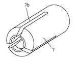
シース1の最先端部分に取り付けられた筒状の先端チップ7は、図1等に示されるように、内径が先細りのテーパ筒状に形成されて、その最先端部分の内径が締め環4の後端外径より小さく形成されている。 As shown in FIG. 1 and the like, the
また、図8に単体で示されるように、締め環4が後方から押し込まれたときそれによって径が押し広げられる状態に弾性変形するよう、先端チップ7の先寄りの部分は軸線と平行方向に複数のスリット7bで分断された形状に形成されている。なお、この実施例ではスリット7bが120°間隔に3個設けられているが、90°間隔に4個或いはそれ以上の個数設けてもよい。 Further, as shown in FIG. 8 alone, when the
このように構成された内視鏡用クリップ装置が使用される際には、図1に示されるように、各クリップ3がシース1内で窄まって連結された状態で、図示されていない内視鏡の処置具挿通チャンネルに通される。 When the endoscope clip device configured as described above is used, as shown in FIG. 1, the
体内でシース1の先端を目標とする患部に向けたら、操作ワイヤ2を基端側から強く押し込む操作をすることにより、図9に示されるように、一連に繋がっている三つのクリップ3A,3B,3Cがシース1内で前方に移動して、締め環4が先端チップ7を押し広げる状態に弾性変形させて先端チップ7の先端から前方に飛び出し、クリップ3がシース1の前方で最大限に広がった状態になる。 When the distal end of the
すると、締め環4の後端部の外径が先端チップ7の先端内径より大きいため、締め環4は逆行して先端チップ7内に戻ることができなくなり、大きく開いた最先端のクリップ3Aをこの状態で目標患部に押しつけることができる。 Then, since the outer diameter of the rear end portion of the
そこで、図10に示されるように、操作ワイヤ2を基端側に牽引操作すると、締め環4の後端が先端チップ7の先端面に当接した状態で、最先端のクリップ3Aの後半部分がシース1内に引き込まれ、それに伴って締め環4が相対的にクリップ3の先寄りの位置に移動することになって、最先端のクリップ3Aが締め環4により強制的に閉じられて目標患部をきつく挟み付けた状態になり、操作ワイヤ2をそれ以上牽引操作することができなくなる。 Therefore, as shown in FIG. 10, when the
そのようになったら、図11に示されるように、操作ワイヤ2を再び先端側に押し込み操作し、図12に示されるように、2番目のクリップ3Bを先端チップ7の先端から押し出せば、2番目のクリップ3Bが開くことにより最先端のクリップ3Aと2番目のクリップ3Bとの連結が外れて、最先端のクリップ3Aが目標患部をクリッピングした状態で体内に留置され、同時に、2番目のクリップ3Bによって次の目標患部に対するクリッピング操作を行うことができる状態になる。 When that happens, as shown in FIG. 11, the
そして、2番目のクリップ3Bによるクリッピング操作が終わったら、同様にして3番目のクリップ3Cによるクリッピング操作を連続して行うことができる。 When the clipping operation by the
1 シース
2 操作ワイヤ
3(3A,3B,3C) クリップ
4 締め環
5 連結部材
7 先端チップ
34 先端爪部
35 当接片
36 連結孔DESCRIPTION OF
Claims (7)
Translated fromJapanese上記各クリップの先端部分に上記各クリップの閉じ方向に向かって折れ曲がった先端爪部が形成されると共に、上記先端爪部を差し込み係合自在な連結孔が、嘴状に開閉動作をする上記クリップの開閉動作面に対し直交する向きに上記各クリップの後端部分に形成され、
隣り合うクリップの先端爪部と連結孔とを係合させることにより、上記複数のクリップが上記シース内において軸線周り方向に90°ずつ交互に向きを変えて直接連結されるようにしたことを特徴とする内視鏡用クリップ装置。A plurality of clips that can be opened and closed in a hook shape are arranged in series in a state where each clip is constricted in the distal end of the sheath inserted into and removed from the treatment instrument insertion channel of the endoscope. In the endoscope clip device configured such that the plurality of clips are sequentially pushed out from the distal end of the sheath by an operation wire disposed so as to freely advance and retract, and the clips can be closed once opened.
The clip is formed with a tip claw portion that is bent toward the closing direction of each clip at the tip portion of each clip, and a connecting hole that can be inserted and engaged with the tip claw portionopens and closes like a hook. Formed in the rear end portion of each clip ina direction orthogonal to the opening / closing operation surface of
The plurality of clips are directly connected to each other by changing the orientation by 90 ° in the direction around the axis in the sheath by engaging the leading end claw portion of the adjacent clip and the connecting hole. An endoscopic clip device.
Priority Applications (1)
| Application Number | Priority Date | Filing Date | Title |
|---|---|---|---|
| JP2005000334AJP4598181B2 (en) | 2005-01-05 | 2005-01-05 | Endoscopic clip device |
Applications Claiming Priority (1)
| Application Number | Priority Date | Filing Date | Title |
|---|---|---|---|
| JP2005000334AJP4598181B2 (en) | 2005-01-05 | 2005-01-05 | Endoscopic clip device |
Publications (2)
| Publication Number | Publication Date |
|---|---|
| JP2006187391A JP2006187391A (en) | 2006-07-20 |
| JP4598181B2true JP4598181B2 (en) | 2010-12-15 |
Family
ID=36795117
Family Applications (1)
| Application Number | Title | Priority Date | Filing Date |
|---|---|---|---|
| JP2005000334AExpired - Fee RelatedJP4598181B2 (en) | 2005-01-05 | 2005-01-05 | Endoscopic clip device |
Country Status (1)
| Country | Link |
|---|---|
| JP (1) | JP4598181B2 (en) |
Cited By (1)
| Publication number | Priority date | Publication date | Assignee | Title |
|---|---|---|---|---|
| WO2021022905A1 (en)* | 2019-08-06 | 2021-02-11 | 南微医学科技股份有限公司 | Tissue clamping and closing device |
Families Citing this family (29)
| Publication number | Priority date | Publication date | Assignee | Title |
|---|---|---|---|---|
| US8080021B2 (en) | 2005-01-11 | 2011-12-20 | Boston Scientific Scimed, Inc. | Multiple clip deployment magazine |
| DE602006004974D1 (en)* | 2005-03-11 | 2009-03-12 | Wilson Cook Medical Inc | DEVICE WITH MULTIPLE CLAMPS |
| US20090228023A1 (en) | 2008-03-04 | 2009-09-10 | Fujifilm Corporation | Clipping device |
| JP2009233318A (en)* | 2008-03-05 | 2009-10-15 | Fujifilm Corp | Repetitive clip treatment tool |
| EP2335610A3 (en) | 2008-03-06 | 2011-12-21 | Fujifilm Corporation | Magazine type clipping device |
| JP2009233317A (en)* | 2008-03-06 | 2009-10-15 | Fujifilm Corp | Magazine type clipping device |
| EP2098176A3 (en) | 2008-03-06 | 2009-10-07 | FUJIFILM Corporation | Magazine type clipping device |
| JP2009233313A (en)* | 2008-03-06 | 2009-10-15 | Fujifilm Corp | Magazine type clipping device |
| JP2009261772A (en)* | 2008-04-28 | 2009-11-12 | Fujifilm Corp | Coupling ring, coupling clip package, and clip loading method |
| EP2113208A3 (en) | 2008-05-02 | 2010-01-20 | Fujifilm Corporation | Multiple clip device and multiple clip application apparatus |
| JP2010063702A (en)* | 2008-09-11 | 2010-03-25 | Fujifilm Corp | Multiple clip unit |
| JP2010012168A (en)* | 2008-07-07 | 2010-01-21 | Fujifilm Corp | Successive clipping device |
| JP2009291237A (en)* | 2008-06-02 | 2009-12-17 | Fujifilm Corp | Repeating clip treatment instrument |
| JP2010035864A (en)* | 2008-08-06 | 2010-02-18 | Fujifilm Corp | Successive clipping device |
| JP2010081963A (en)* | 2008-09-29 | 2010-04-15 | Fujifilm Corp | Clip treatment tool operation handle and repetitive clip treatment tool |
| JP2010012212A (en)* | 2008-06-03 | 2010-01-21 | Fujifilm Corp | Successive clipping device |
| JP2009291535A (en)* | 2008-06-09 | 2009-12-17 | Fujifilm Corp | Repeating clip treatment instrument |
| JP2010012171A (en)* | 2008-07-07 | 2010-01-21 | Fujifilm Corp | Coupling clip package |
| JP2010012170A (en)* | 2008-07-07 | 2010-01-21 | Fujifilm Corp | Coupling clip package |
| JP2010063701A (en)* | 2008-09-11 | 2010-03-25 | Fujifilm Corp | Multiple clip package |
| JP2010029629A (en)* | 2008-06-30 | 2010-02-12 | Fujifilm Corp | Clip treatment tool |
| JP2010051547A (en)* | 2008-08-28 | 2010-03-11 | Fujifilm Corp | Manipulating handle for successive clip treatment device, and successive clip treatment device using the same |
| JP2010022537A (en)* | 2008-07-17 | 2010-02-04 | Fujifilm Corp | Manipulating handle for successive clipping device and successive clipping device using same |
| JP2010035819A (en)* | 2008-08-05 | 2010-02-18 | Fujifilm Corp | Successive clipping device |
| JP2010035853A (en) | 2008-08-06 | 2010-02-18 | Fujifilm Corp | Successive clipping device |
| JP5280767B2 (en)* | 2008-08-14 | 2013-09-04 | 富士フイルム株式会社 | Repetitive clip treatment tool |
| JP5064334B2 (en) | 2008-08-21 | 2012-10-31 | 富士フイルム株式会社 | Clip package and clip loading method |
| JP2010119682A (en)* | 2008-11-20 | 2010-06-03 | Fujifilm Corp | Cylindrical member, and multiple clip application device |
| CN103124530B (en)* | 2010-09-22 | 2016-03-30 | 富士胶片株式会社 | Apparatus for ligating and the clip unit used in this apparatus for ligating |
Family Cites Families (4)
| Publication number | Priority date | Publication date | Assignee | Title |
|---|---|---|---|---|
| US5100418A (en)* | 1987-05-14 | 1992-03-31 | Inbae Yoon | Suture tie device system and applicator therefor |
| JPH06237939A (en)* | 1993-02-17 | 1994-08-30 | Olympus Optical Co Ltd | Clip device |
| JP4472217B2 (en)* | 2000-10-16 | 2010-06-02 | オリンパス株式会社 | Biological tissue clip device |
| JP4059656B2 (en)* | 2001-03-07 | 2008-03-12 | オリンパス株式会社 | Biological tissue clip device |
- 2005
- 2005-01-05JPJP2005000334Apatent/JP4598181B2/ennot_activeExpired - Fee Related
Cited By (1)
| Publication number | Priority date | Publication date | Assignee | Title |
|---|---|---|---|---|
| WO2021022905A1 (en)* | 2019-08-06 | 2021-02-11 | 南微医学科技股份有限公司 | Tissue clamping and closing device |
Also Published As
| Publication number | Publication date |
|---|---|
| JP2006187391A (en) | 2006-07-20 |
Similar Documents
| Publication | Publication Date | Title |
|---|---|---|
| JP4598181B2 (en) | Endoscopic clip device | |
| JP4716513B2 (en) | Endoscopic clip device | |
| JP5006753B2 (en) | Endoscopic clip device | |
| JP5486983B2 (en) | Ligation device | |
| JP6084347B1 (en) | Endoscopic treatment tool | |
| JP4394634B2 (en) | Endoscope clip removal device | |
| WO2016185965A1 (en) | Clip device | |
| JP4261450B2 (en) | Endoscopic clip device | |
| JP2013085860A (en) | Clip device | |
| JP4476237B2 (en) | Endoscopic clip device | |
| JP2007275269A (en) | Endoscopic clip device | |
| US20090223028A1 (en) | Magazine type clipping device | |
| JP2013244054A (en) | Medical gripping instrument | |
| JP2015192724A (en) | Hold releasing device of body tissue holding member | |
| JP2007283015A (en) | Endoscopic clip device | |
| JP2007283080A (en) | Endoscope clip | |
| JP4491590B2 (en) | Endoscope clip | |
| JP4575749B2 (en) | Endoscopic clip device | |
| JP2007136128A (en) | Endoscopic clip device | |
| JP4575763B2 (en) | Endoscopic clip device | |
| JP4491589B2 (en) | Endoscopic clip device | |
| JP4273040B2 (en) | Endoscopic clip device | |
| JP2002360591A (en) | Endoscope clip device | |
| JP3917466B2 (en) | Endoscopic clip device | |
| JP2004321343A (en) | Endoscope clip device |
Legal Events
| Date | Code | Title | Description |
|---|---|---|---|
| A621 | Written request for application examination | Free format text:JAPANESE INTERMEDIATE CODE: A621 Effective date:20071212 | |
| A711 | Notification of change in applicant | Free format text:JAPANESE INTERMEDIATE CODE: A712 Effective date:20080501 | |
| A977 | Report on retrieval | Free format text:JAPANESE INTERMEDIATE CODE: A971007 Effective date:20100514 | |
| A131 | Notification of reasons for refusal | Free format text:JAPANESE INTERMEDIATE CODE: A131 Effective date:20100527 | |
| A521 | Request for written amendment filed | Free format text:JAPANESE INTERMEDIATE CODE: A523 Effective date:20100721 | |
| TRDD | Decision of grant or rejection written | ||
| A01 | Written decision to grant a patent or to grant a registration (utility model) | Free format text:JAPANESE INTERMEDIATE CODE: A01 Effective date:20100909 | |
| A01 | Written decision to grant a patent or to grant a registration (utility model) | Free format text:JAPANESE INTERMEDIATE CODE: A01 | |
| A61 | First payment of annual fees (during grant procedure) | Free format text:JAPANESE INTERMEDIATE CODE: A61 Effective date:20100923 | |
| R150 | Certificate of patent or registration of utility model | Free format text:JAPANESE INTERMEDIATE CODE: R150 | |
| FPAY | Renewal fee payment (event date is renewal date of database) | Free format text:PAYMENT UNTIL: 20131001 Year of fee payment:3 | |
| LAPS | Cancellation because of no payment of annual fees |