JP4598003B2 - Transmission control frame generation device, transmission control frame processing device, transmission control frame generation method, and transmission control frame processing method - Google Patents
Transmission control frame generation device, transmission control frame processing device, transmission control frame generation method, and transmission control frame processing methodDownload PDFInfo
- Publication number
- JP4598003B2 JP4598003B2JP2006547899AJP2006547899AJP4598003B2JP 4598003 B2JP4598003 B2JP 4598003B2JP 2006547899 AJP2006547899 AJP 2006547899AJP 2006547899 AJP2006547899 AJP 2006547899AJP 4598003 B2JP4598003 B2JP 4598003B2
- Authority
- JP
- Japan
- Prior art keywords
- line state
- state level
- subcarrier
- value
- snr value
- Prior art date
- Legal status (The legal status is an assumption and is not a legal conclusion. Google has not performed a legal analysis and makes no representation as to the accuracy of the status listed.)
- Expired - Fee Related
Links
Images


Classifications
- H—ELECTRICITY
- H04—ELECTRIC COMMUNICATION TECHNIQUE
- H04L—TRANSMISSION OF DIGITAL INFORMATION, e.g. TELEGRAPHIC COMMUNICATION
- H04L5/00—Arrangements affording multiple use of the transmission path
- H04L5/003—Arrangements for allocating sub-channels of the transmission path
- H04L5/0058—Allocation criteria
- H04L5/006—Quality of the received signal, e.g. BER, SNR, water filling
- H—ELECTRICITY
- H04—ELECTRIC COMMUNICATION TECHNIQUE
- H04B—TRANSMISSION
- H04B1/00—Details of transmission systems, not covered by a single one of groups H04B3/00 - H04B13/00; Details of transmission systems not characterised by the medium used for transmission
- H04B1/69—Spread spectrum techniques
- H04B1/707—Spread spectrum techniques using direct sequence modulation
- H04B1/7097—Interference-related aspects
- H04B1/711—Interference-related aspects the interference being multi-path interference
- H04B1/7115—Constructive combining of multi-path signals, i.e. RAKE receivers
- H—ELECTRICITY
- H04—ELECTRIC COMMUNICATION TECHNIQUE
- H04L—TRANSMISSION OF DIGITAL INFORMATION, e.g. TELEGRAPHIC COMMUNICATION
- H04L5/00—Arrangements affording multiple use of the transmission path
- H04L5/0001—Arrangements for dividing the transmission path
- H04L5/0003—Two-dimensional division
- H04L5/0005—Time-frequency
- H04L5/0007—Time-frequency the frequencies being orthogonal, e.g. OFDM(A) or DMT
- H—ELECTRICITY
- H04—ELECTRIC COMMUNICATION TECHNIQUE
- H04L—TRANSMISSION OF DIGITAL INFORMATION, e.g. TELEGRAPHIC COMMUNICATION
- H04L5/00—Arrangements affording multiple use of the transmission path
- H04L5/003—Arrangements for allocating sub-channels of the transmission path
- H04L5/0044—Allocation of payload; Allocation of data channels, e.g. PDSCH or PUSCH
- H04L5/0046—Determination of the number of bits transmitted on different sub-channels
- H—ELECTRICITY
- H04—ELECTRIC COMMUNICATION TECHNIQUE
- H04B—TRANSMISSION
- H04B2201/00—Indexing scheme relating to details of transmission systems not covered by a single group of H04B3/00 - H04B13/00
- H04B2201/69—Orthogonal indexing scheme relating to spread spectrum techniques in general
- H04B2201/707—Orthogonal indexing scheme relating to spread spectrum techniques in general relating to direct sequence modulation
- H04B2201/7097—Direct sequence modulation interference
- H04B2201/709709—Methods of preventing interference
- H—ELECTRICITY
- H04—ELECTRIC COMMUNICATION TECHNIQUE
- H04J—MULTIPLEX COMMUNICATION
- H04J13/00—Code division multiplex systems
- H04J13/16—Code allocation
- H04J13/18—Allocation of orthogonal codes
Landscapes
- Engineering & Computer Science (AREA)
- Signal Processing (AREA)
- Computer Networks & Wireless Communication (AREA)
- Quality & Reliability (AREA)
- Mobile Radio Communication Systems (AREA)
- Communication Control (AREA)
- Detection And Prevention Of Errors In Transmission (AREA)
Description
Translated fromJapanese本発明は、マルチキャリア伝送方式の移動通信システムで用いられる送信制御フレーム生成装置、送信制御フレーム処理装置、送信制御フレーム生成方法および送信制御フレーム処理方法に関する。 The present invention relates to a transmission control frame generation device, a transmission control frame processing device, a transmission control frame generation method, and a transmission control frame processing method used in a mobile communication system of a multicarrier transmission system.
第4世代などの次世代移動通信システムでは、高速移動時においても100Mbpsを超えるデータレートが要求される。その要求を満たすために100MHz程度の帯域幅を使った様々な無線通信が検討されている。その中でも特に、周波数選択性フェージング環境への適応性や周波数利用効率の観点から、OFDM(Orthogonal Frequency Division Multiplexing)方式に代表されるマルチキャリア伝送方式が次世代移動通信システムの伝送方式として有力視されている。 In next-generation mobile communication systems such as the fourth generation, a data rate exceeding 100 Mbps is required even during high-speed movement. In order to satisfy this requirement, various wireless communications using a bandwidth of about 100 MHz are being studied. In particular, from the viewpoint of adaptability to a frequency selective fading environment and frequency utilization efficiency, a multicarrier transmission system represented by the OFDM (Orthogonal Frequency Division Multiplexing) system is regarded as a promising transmission system for next-generation mobile communication systems. ing.
マルチキャリア伝送方式の移動通信システムで高スループットを実現するために検討されている技術の一つに、下記の適応送信制御が挙げられる。適応送信制御では、サブキャリア毎またはサブキャリアグループ毎の回線状態を推定し、その推定結果を示す回線状態情報(CSI:Channel State Information)に基づいて、例えば誤り訂正能力、変調多値数、電力、位相、送信アンテナなどの変調パラメータをサブキャリア毎またはサブキャリアグループ毎に適応的に制御する。サブキャリアグループは、マルチキャリア伝送に用いられる帯域全体の中の一区域であり、一つ以上のサブキャリアを含む。 The following adaptive transmission control is mentioned as one of the techniques studied in order to realize high throughput in a multi-carrier transmission mobile communication system. In adaptive transmission control, the channel state for each subcarrier or each subcarrier group is estimated, and based on channel state information (CSI: Channel State Information) indicating the estimation result, for example, error correction capability, number of modulation levels, power Modulation parameters such as phase and transmission antenna are adaptively controlled for each subcarrier or each subcarrier group. A subcarrier group is an area in the entire band used for multicarrier transmission, and includes one or more subcarriers.
なお、サブキャリアグループ毎に変調パラメータ制御を行うための構成および動作は、サブキャリア毎に変調パラメータ制御を行うための構成および動作と基本的に同じである。よって、説明簡略化のために以下の説明では、サブキャリア毎の変調パラメータ制御についてのみ言及する。サブキャリアグループ毎の変調パラメータ制御は、「サブキャリア」を「サブキャリアグループ」と適宜読み替えることにより実施することができる。 The configuration and operation for performing modulation parameter control for each subcarrier group are basically the same as the configuration and operation for performing modulation parameter control for each subcarrier. Therefore, for simplification of description, the following description refers only to modulation parameter control for each subcarrier. The modulation parameter control for each subcarrier group can be performed by appropriately replacing “subcarrier” with “subcarrier group”.
適応送信制御には、クローズドループ型のものがある。つまり、制御対象のサブキャリアで送信された情報を受信する装置では、そのサブキャリアのCSI値をフィードバックする。一方、制御対象のサブキャリアで情報を送信する装置では、フィードバック情報を受信し、その情報に基づいて、そのサブキャリアについての変調パラメータを適応的に制御する。 There is a closed loop type of adaptive transmission control. That is, an apparatus that receives information transmitted on a subcarrier to be controlled feeds back the CSI value of that subcarrier. On the other hand, an apparatus that transmits information using subcarriers to be controlled receives feedback information and adaptively controls modulation parameters for the subcarriers based on the information.
クローズドループ型の適応送信制御に関して、サブキャリア数の増加に伴うフィードバック情報のオーバーヘッドの増大に対処するための様々な手法が提案されている。 With respect to closed-loop adaptive transmission control, various methods have been proposed to cope with an increase in overhead of feedback information accompanying an increase in the number of subcarriers.
例えば、非特許文献1に記載された従来の適応送信制御では、各サブキャリアについて、ある時刻にフィードバックしたCSI値とその直後のCSI値との差を符号化することにより、圧縮されたフィードバック情報を生成する。 For example, in the conventional adaptive transmission control described in Non-Patent
また、従来の適応送信制御の他の例では、周波数軸方向において相互に隣接する2つのサブキャリアについてのCSI値の差を符号化することにより、圧縮されたフィードバック情報を生成する。 In another example of conventional adaptive transmission control, compressed feedback information is generated by encoding a difference between CSI values for two subcarriers adjacent to each other in the frequency axis direction.
上記のように、連続するサンプル間の相関が高いことを利用してサンプル間の差を符号化する技術は一般に差分符号化(Differential Coding)と呼ばれる。差分符号化は、音声符号化などの分野で古くから確立されている。差分符号化の方式としては、例えばDPCM(Differential Pulse Code Modulation)、DM(Delta Modulation)、ADPCM(Adaptive Differential Pulse Code Modulation)、ADM(Adaptive Delta Modulation)などが挙げられる(例えば、非特許文献2、非特許文献3参照)。
しかしながら、前述の既存の差分符号化によるデータ圧縮技術は、本来、音声や画像を対象情報源として考案された技術である。よって、サブキャリア毎のCSI値からフィードバック情報を生成するのに対して単に既存の差分符号化を導入するだけでは、フィードバック情報のデータ量の削減に一定の限界がある。 However, the above-described data compression technique based on the differential encoding is originally a technique devised using audio and images as the target information source. Therefore, when the feedback information is generated from the CSI value for each subcarrier and the existing differential coding is simply introduced, there is a certain limit in reducing the data amount of the feedback information.
また、マルチキャリア伝送のスループットを十分に実用的なレベルに維持するためには、フィードバック情報の品質を一定レベル以上に維持することが要求される。 In order to maintain the throughput of multicarrier transmission at a sufficiently practical level, it is required to maintain the quality of feedback information at a certain level or higher.
本発明の目的は、フィードバック情報の品質を維持しつつ、フィードバック情報のデータ量を削減することができる送信制御フレーム生成装置、送信制御フレーム処理装置、送信制御フレーム生成方法および送信制御フレーム処理方法を提供することである。 An object of the present invention is to provide a transmission control frame generation device, a transmission control frame processing device, a transmission control frame generation method, and a transmission control frame processing method capable of reducing the data amount of feedback information while maintaining the quality of feedback information. Is to provide.
本発明の送信制御フレーム生成装置は、複数のサブキャリアにそれぞれ対応する複数の回線状態レベルから、前記複数のサブキャリア間の基準回線状態レベルを算出する基準レベル算出手段と、前記複数のサブキャリアのうち一のサブキャリアと他のサブキャリアとにそれぞれ対応する第1回線状態レベルと第2回線状態レベルとの差分値に対して符号化を施して、符号化差分値を得る符号化手段と、前記基準回線状態レベルと前記符号化差分値とを示すフレームを生成する生成手段と、前記差分値に対して施される前記符号化を、前記第1回線状態レベルおよび前記第2回線状態レベルのいずれか一方の前記基準回線状態レベルに対する相対的大きさに基づいて制御する符号化制御手段と、を有する構成を採る。 The transmission control frame generation device of the present invention includes a reference level calculation means for calculating a reference line state level between the plurality of subcarriers from a plurality of line state levels respectively corresponding to the plurality of subcarriers, and the plurality of subcarriers Encoding means for encoding the difference value between the first channel state level and the second channel state level respectively corresponding to one of the subcarriers and the other subcarrier to obtain an encoded difference value; Generation means for generating a frame indicating the reference line state level and the encoded difference value; and encoding performed on the difference value, the first line state level and the second line state level. And a coding control means for controlling based on a relative magnitude with respect to any one of the reference line state levels.
本発明の送信制御フレーム処理装置は、複数のサブキャリア間の基準回線状態レベルを示すフレームであって、前記複数のサブキャリアのうち一のサブキャリアと他のサブキャリアとにそれぞれ対応する第1回線状態レベルと第2回線状態レベルとの差分値をさらに示すフレームを取得する取得手段と、前記差分値に対して復号化を施して、復号化差分値を得る復号化手段と、前記第1回線状態レベルおよび前記第2回線状態レベルのいずれか一方を、前記復号化差分値を用いて算出する個別レベル算出手段と、前記差分値に対して施される前記復号化を、前記第1回線状態レベルおよび前記第2回線状態レベルのいずれか一方の前記基準回線状態レベルに対する相対的大きさに基づいて制御する復号化制御手段と、を有する構成を採る。 The transmission control frame processing apparatus of the present invention is a frame indicating a reference channel state level between a plurality of subcarriers, and each of the first subcarriers corresponds to one subcarrier and another subcarrier among the plurality of subcarriers. Obtaining means for obtaining a frame further indicating a difference value between the line state level and the second line state level; decoding means for performing decoding on the difference value to obtain a decoded difference value; and the first Individual level calculation means for calculating one of a line state level and the second line state level using the decoded difference value; and the decoding applied to the difference value, the first line And a decoding control means for controlling based on a relative magnitude of one of the state level and the second line state level with respect to the reference line state level.
本発明の送信制御フレーム生成方法は、複数のサブキャリアにそれぞれ対応する複数の回線状態レベルから、前記複数のサブキャリア間の基準回線状態レベルを算出する基準レベル算出ステップと、前記複数のサブキャリアのうち一のサブキャリアと他のサブキャリアとにそれぞれ対応する第1回線状態レベルと第2回線状態レベルとの差分値に対して符号化を施して、符号化差分値を得る符号化ステップと、前記基準回線状態レベルと前記符号化差分値とを示すフレームを生成する生成ステップと、前記差分値に対して施される前記符号化を、前記第1回線状態レベルおよび前記第2回線状態レベルのいずれか一方の前記基準回線状態レベルに対する相対的大きさに基づいて制御する符号化制御ステップと、を有するようにした。 The transmission control frame generation method of the present invention includes a reference level calculation step of calculating a reference channel state level between the plurality of subcarriers from a plurality of channel state levels respectively corresponding to the plurality of subcarriers, and the plurality of subcarriers Encoding a difference value between the first channel state level and the second channel state level respectively corresponding to one of the subcarriers and the other subcarrier to obtain an encoded difference value; Generating a frame indicating the reference line state level and the encoded difference value, and performing the encoding performed on the difference value as the first line state level and the second line state level. And an encoding control step for controlling based on a relative magnitude with respect to any one of the reference line state levels.
本発明の送信制御フレーム処理方法は、複数のサブキャリア間の基準回線状態レベルを示すフレームであって、前記複数のサブキャリアのうち一のサブキャリアと他のサブキャリアとにそれぞれ対応する第1回線状態レベルと第2回線状態レベルとの差分値をさらに示すフレームを取得する取得ステップと、前記差分値に対して復号化を施して、復号化差分値を得る復号化ステップと、前記第1回線状態レベルおよび前記第2回線状態レベルのいずれか一方を、前記復号化差分値を用いて算出する個別レベル算出ステップと、前記差分値に対して施される前記復号化を、前記第1回線状態レベルおよび前記第2回線状態レベルのいずれか一方の前記基準回線状態レベルに対する相対的大きさに基づいて制御する復号化制御ステップと、を有するようにした。 The transmission control frame processing method of the present invention is a frame indicating a reference channel state level between a plurality of subcarriers, and each of the first subcarriers corresponds to one subcarrier and another subcarrier among the plurality of subcarriers. An acquisition step of acquiring a frame further indicating a difference value between the line state level and the second line state level; a decoding step of performing decoding on the difference value to obtain a decoded difference value; An individual level calculation step of calculating one of a line state level and the second line state level using the decoded difference value, and the decoding performed on the difference value, the first line And a decoding control step for controlling based on a relative magnitude of one of the state level and the second line state level with respect to the reference line state level. It was so.
本発明によれば、フィードバック情報の品質を維持しつつ、フィードバック情報のデータ量を削減することができる。 According to the present invention, it is possible to reduce the data amount of feedback information while maintaining the quality of feedback information.
以下、本発明の実施の形態について、図面を用いて詳細に説明する。 Hereinafter, embodiments of the present invention will be described in detail with reference to the drawings.
(実施の形態1)
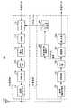
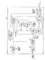
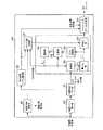
図1は、本発明の実施の形態1に係る送信制御フレーム処理装置を備えた無線通信装置の構成を示すブロック図である。また、図2は、本発明の実施の形態1に係る送信制御フレーム生成装置を備えた無線通信装置の構成を示すブロック図である。なお、送信制御フレーム処理装置を備えた無線通信装置は、制御対象のサブキャリアで情報(情報データ列)を送信する装置であるため、以下の説明では「送信装置」と言う。一方、送信制御フレーム生成装置を備えた無線通信装置は、制御対象のサブキャリアで送信された情報(情報データ列)を受信する装置であるため、以下の説明では「受信装置」と言う。図1の送信装置100および図2の受信装置150は、移動通信システムにおいて使用される基地局装置や通信端末装置などに搭載される。なお、基地局装置はNode B、通信端末装置はUE、サブキャリアはトーン(Tone)と表されることがある。(Embodiment 1)
FIG. 1 is a block diagram showing a configuration of a wireless communication apparatus provided with a transmission control frame processing apparatus according to
送信装置100は、送信部101、受信部102およびアンテナ103を有する。送信部101は、CSIフレーム処理部110、変調パラメータ決定部111、符号化部112、変調部113、電力制御部114、IFFT(Inverse Fast Fourier Transform)部115、GI(Guard Interval)挿入部116および送信無線処理部117を有する。受信部102は、受信無線処理部120、GI除去部121、FFT(Fast Fourier Transform)部122、復調部123および復号化部124を有する。 The
CSIフレーム処理装置としてのCSIフレーム処理部110は、復号化部124の復号処理で得られたCSIフレームから、サブキャリア毎の回線状態情報(以下、CSIと呼ぶ)を得る。CSIフレーム処理部110の構成およびその動作については後で詳述する。なお、CSIはCQI(Channel Quality Indicator)と表されることがある。 A CSI
変調パラメータ決定部111は、CSIフレーム処理部110から入力されるサブキャリア毎のCSIに基づいて、サブキャリア毎の変調パラメータ(誤り訂正符号、符号化率、変調方式および送信電力)を決定する。すなわち、各サブキャリアでの送信を、決定された誤り訂正符号、符号化率、変調方式および送信電力で制御する。 Modulation
符号化部112は、入力される時系列の送信データを、変調パラメータ決定部111から指示された誤り訂正符号化方式および符号化率でサブキャリア毎に符号化する。変調部113は、符号化された送信データを、変調パラメータ決定部111から指示された変調方式(例えばM−PSKやM−QAMなど)によってサブキャリア毎に変調する。電力制御部114は、サブキャリア毎の送信電力を、変調パラメータ決定部111から指示された送信電力値に設定する。IFFT部115は、サブキャリア毎に変調された信号を複数の直交するサブキャリアで多重するIFFT処理を行い、マルチキャリア信号であるOFDMシンボルを生成する。GI挿入部116は、遅延波によるシンボル間干渉(ISI:Inter Symbol Interference)を低減するために、OFDMシンボル間にGIを挿入する。
送信無線処理部117は、OFDMシンボルにアップコンバートなどの所定の無線処理を施して、無線処理後のOFDMシンボルをアンテナ103から受信装置150へ送信する。すなわち、各サブキャリアに重畳された送信データ列を無線送信する。 Transmission
受信無線処理部120は、アンテナ103で受信されるOFDMシンボルに対してダウンコンバートなどの所定の無線処理を施す。受信されるOFDMシンボルには、フレーム化されたCSI(CSIフレーム)が含まれている。すなわち、受信無線処理部120は、CSIフレームを受信する。 The reception
GI除去部121は、OFDMシンボル間に挿入されているGIを除去する。FFT部122は、GI除去後のOFDMシンボルに対してFFT処理を行い、サブキャリア毎の信号を得る。復調部123は、FFT後の信号を復調し、復号化部124は、変調後の信号を復号する。これにより受信データが得られる。受信データには、データフレームおよびCSIフレームが含まれている。
図2の受信装置150は、アンテナ151、受信部152および送信部153を有する。受信部152は、受信無線処理部160、GI除去部161、FFT部162、復調部163、復号化部164、伝送路応答推定部165およびCSIフレーム生成部166を有する。送信部153は、符号化部170、変調部171、電力制御部172、IFFT部173、GI挿入部174および送信無線処理部175を有する。 2 includes an
受信無線処理部160は、アンテナ151で受信されるOFDMシンボルに対してダウンコンバートなどの所定の無線処理を施す。すなわち、受信無線処理部160は、各サブキャリアに重畳されたデータ列を受信する。 Reception
GI除去部161は、OFDMシンボル間に挿入されているGIを除去する。FFT部162は、GI除去後のOFDMシンボルに対してFFT処理を行い、サブキャリア毎の信号を得る。復調部163には、FFT後の信号のうち、パイロット信号等を除いた情報信号が入力される。復調部163は、送信装置100での変調に使用された変調方式に対応する復調方式で情報信号を復調する。復号化部164は、送信装置100での符号化に使用された符号化方式に対応する復号化方式で変調後の信号に対して誤り訂正などの復号処理を行って受信データを得る。
伝送路応答推定部165には、FFT後の信号のうち、パイロット信号などの伝送路応答の推定に必要な信号が入力される。伝送路応答推定部165は、サブキャリア毎の伝送路応答を推定し、伝送路応答推定値(伝搬路推定値)を得る。 Of the signals after FFT, a signal necessary for estimating the transmission path response, such as a pilot signal, is input to transmission path
送信制御フレーム生成装置としてのCSIフレーム生成部166は、伝搬路推定値に基づいてサブキャリア毎のCSIを求め、それらのCSIを送信装置100へフィードバックするためのCSIフレームを生成する。CSIフレーム生成部166の構成やその動作については後で詳述する。 The CSI
符号化部170は、入力される時系列の送信データおよびCSIフレームを、所定の符号化方式および符号化率でサブキャリア毎に符号化する。変調部171は、符号化された送信データおよびCSIフレームを、所定の変調方式によってサブキャリア毎に変調する。電力制御部172は、サブキャリア毎の送信電力を制御する。IFFT部173は、サブキャリア毎に変調された信号を複数の直交するサブキャリアで多重するIFFT処理を行い、マルチキャリア信号であるOFDMシンボルを生成する。GI挿入部174は、遅延波によるISIを低減するために、OFDMシンボル間にGIを挿入する。送信手段としての送信無線処理部175は、OFDMシンボルにアップコンバートなどの所定の無線処理を施して、無線処理後のOFDMシンボルをアンテナ151から送信装置100へ送信する。すなわち、送信無線処理部175は、生成されたCSIフレームを無線送信する。
次いで、CSIフレーム生成部166の内部構成およびその動作について説明する。CSIフレーム生成部166は、図3に示すように、品質レベル算出部180、回線状態メモリ部181、平均品質レベル算出部182、ビット数制御部183、DPCM部184およびフィードバックフレーム生成部185を有する。DPCM部184は、減算部190、量子化部191、ビット変換部192、加算部193、遅延部194および符号化部195を有する。 Next, the internal configuration and operation of the CSI
品質レベル算出部180は、回線状態を示す値として、伝送路応答推定部165より入力されるサブキャリア毎の伝搬路推定値からサブキャリア毎のSNR(Signal to Noise Ratio)値を算出する。 Quality
なお、以下の説明において言及するSNR値は、真値の使用について言及した場合を除いて、対数値である。また、ここでは品質レベル(回線状態レベル)を表す指標としてSNRを用いた場合を例にとって説明しているが、SNRの代わりにCNR(Carrier to Noise Ratio)、受信電力、RSSI(Received Signal Strength Indicator)、受信振幅などを回線状態レベルとして用いても良い。また、セルラシステムのように雑音電力だけでなく干渉電力もCSIとして重要となる通信システムでは、SIR(Signal to Interference Ratio)、CIR(Carrier to Interference Ratio)、SINR(Signal to Interference and Noise Ratio)、CINR(Carrier to Interference and Noise Ratio)などを回線状態レベルとして用いても良い。あるいは、前述の指標で示された数値から算出されるローディングビット数、送信電力または送信複素重み係数などの制御値を回線状態レベルとして用いても良い。あるいは、MIMO(Multi-Input Multi-Output)方式が採用されている場合は、特異値分解、固有値分解またはQR分解によって得られる行列もしくは特異値または固有値などの値を、回線状態レベルとして用いても良い。また、SNRやSIRより算出される、MCS(Modulation and Coding Scheme)パラメータ(変調方式、符号化率、送信電力など)をCSI情報として用いても良い。 Note that the SNR value referred to in the following description is a logarithmic value except when referring to the use of a true value. Further, here, a case where SNR is used as an index representing a quality level (line state level) has been described as an example, but instead of SNR, CNR (Carrier to Noise Ratio), received power, RSSI (Received Signal Strength Indicator). ), Reception amplitude or the like may be used as the line state level. Moreover, in a communication system in which not only noise power but also interference power is important as CSI as in a cellular system, SIR (Signal to Interference Ratio), CIR (Carrier to Interference Ratio), SINR (Signal to Interference and Noise Ratio), CINR (Carrier to Interference and Noise Ratio) or the like may be used as the line state level. Alternatively, a control value such as the number of loading bits, transmission power, or transmission complex weight coefficient calculated from the numerical value indicated by the above-described index may be used as the line state level. Alternatively, when a MIMO (Multi-Input Multi-Output) method is adopted, a matrix or a value such as a singular value or eigenvalue obtained by singular value decomposition, eigenvalue decomposition, or QR decomposition may be used as the line state level. good. Further, MCS (Modulation and Coding Scheme) parameters (modulation scheme, coding rate, transmission power, etc.) calculated from SNR and SIR may be used as CSI information.
回線状態メモリ部181は、品質レベル算出部180により算出されたサブキャリア毎のSNR値を保持する。また、各サブキャリアに識別情報として付与された番号(順序)に従ってサブキャリア毎のSNR値を減算部190に順次出力する。 The line
算出手段としての平均品質レベル算出部182は、回線状態メモリ部181に保持されたサブキャリア毎のSNR値を用いて、全サブキャリアに渡る平均SNR値を算出する。平均SNR値は、ある時刻での全サブキャリアのSNR値を平均したものでも良いし、ある期間内での全サブキャリアのSNR値を平均したものでも良い。 The average quality
なお、本実施の形態では、算出された平均SNR値を全サブキャリアの基準品質レベルとして用いているが、平均SNR値の変わりに、全サブキャリアのSNR値の中央値、最小値または最大値などを用いても良い。 In the present embodiment, the calculated average SNR value is used as the reference quality level of all subcarriers. Instead of the average SNR value, the median, minimum value, or maximum value of the SNR values of all subcarriers is used. Etc. may be used.
符号化制御手段としてのビット数制御部183は、サブキャリア毎のSNR値の平均SNR値に対する相対的大きさに基づいて、符号化部195での符号化に用いるビット数を可変設定することにより、DPCM部184の符号化処理を制御する。換言すれば、符号化部195で生成される差分SNR値に可変のビット数を割り当てる。割り当てられたビット数は、符号化部195に通知される。 The bit
符号化手段としてのDPCM部184において、減算部190は、回線状態メモリ部181から入力されたSNR値から、遅延部194から入力されたSNR値を減算して、差分SNR値を算出する。ただし、サブキャリアf1のSNR値についてはそのまま量子化部191に出力する。In the DPCM unit 184 as an encoding means, the subtracting
量子化部191は、差分SNR値(またはSNR値)を、予め設定されているステップ幅で量子化する。 The
ビット変換部192は、量子化部191によって量子化された差分SNR値(またはSNR値)のステップ幅を変換する。この変換により、差分SNR値(またはSNR値)のステップ幅を、量子化部191の量子化に用いるステップ幅から、加算部193の加算に用いるステップ幅に合わせる。 The
加算部193は、量子化部191によって量子化された差分SNR値と遅延部194から入力されたSNR値とを加算する。加算結果は遅延部194に出力される。ただし、サブキャリアf1の量子化後のSNR値についてはそのまま遅延部194に出力する。The
遅延部194は、内部の状態値を、加算部193の出力で更新する。そして、更新された状態値を1サブキャリア分だけ遅延して、加算部193、減算部190およびビット数制御部183に出力する。 The
符号化部195は、量子化部191によって量子化された差分SNR値(またはSNR値)に対して、ビット数制御部183から通知されたビット数で符号化する。 The
生成手段としてのフィードバックフレーム生成部185は、平均品質レベル算出部182によって算出された平均SNR値と符号化部195によって符号化されたサブキャリア毎の差分SNR値とを用いてCSIフレームを生成する。 A feedback
続いて、CSIフレーム生成部166における動作の一例について説明する。 Next, an example of the operation in the CSI
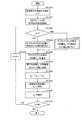
図4には、CSIフレーム生成部166の動作例を説明するためのフロー図が示されている。また、図5Aおよび図5Bには、送受信局間でやりとりするOFDMフレームの構成、伝送路応答推定タイミングおよび周波数応答推定値の一例が示されている。送信装置100と受信装置150との間で利用されるOFDMフレームにおいては、例えば図5Aのように、伝送路の周波数応答を推定するための伝送路応答推定用キャリア(例えば、既知のパイロット信号)が、データなど他の目的に利用されるデータキャリアの間に所定間隔で挿入される。伝送路応答推定部165では、伝送路応答推定用キャリアを用いて、サブキャリア毎の伝送路で受けた振幅変動および位相変動を、時刻tk(kは整数)のタイミングで推定し、これらの推定結果を品質レベル算出部180に出力する。なお、ブラインド推定をするようなシステムでは、伝送路推定用キャリアとしてデータ用キャリアが使用されることがある。FIG. 4 is a flowchart for explaining an operation example of the CSI
まず、CSIフレーム生成部166のCSIフレーム生成処理開始に際して、遅延部194の状態値が「0」に初期化されるとともに、カウンタmの値が「1」に初期化される(ST1010)。 First, at the start of CSI frame generation processing by CSI
そして、品質レベル算出部180で、受け取った周波数応答推定値から図5Bのようにサブキャリア毎にSNR値γm,kを算出する(ST1020)。ここで、SNR値γm,kはm番目のサブキャリア(m=1,2,3,…,M−1,M)の時間tkでのSNR値を対数変換した値を表す。また、Mは全サブキャリア数を表す。Then, quality
品質レベル算出部180で算出されたSNR値γm,kは、回線状態メモリ部181に記憶される。回線状態メモリ部181に記憶されるSNR値γm,kは、品質レベル算出部180で新たに算出されるたびに更新される。The SNR value γm, k calculated by the quality
なお、伝送路応答推定値の更新およびSNR値γm,kの算出の頻度は、CSIフレームのフィードバック周期と同じかそれよりも小さく設定される。また、更新周期は、フィードバック周期と独立に設定されても良い。ただし、CSIフレーム生成途中での回線状態メモリ部181への更新処理は発生しないように制御される。The frequency of updating the channel response estimated value and calculating the SNR value γm, k is set to be the same as or smaller than the feedback period of the CSI frame. Further, the update cycle may be set independently of the feedback cycle. However, control is performed so that update processing to the line
サブキャリア毎に算出されたSNR値γm,kは、平均品質レベル算出部182にて、全サブキャリアに渡る平均SNR値を算出するために利用される(ST1030)。平均SNR値は、次の式(1)により求められる。また、時間tkで推定したm番目のサブキャリアのSNR値の真値は、次の式(2)で表され、全サブキャリアについての真値のSNR値の平均値は、次の式(3)で表される。
なお、この例示においては、平均SNR値の算出に、対数値から真値に戻されたSNR値が用いられているが、品質レベル算出部180でSNR値を算出する過程で得られるSNR値の真値が用いられても良い。 In this example, the SNR value returned from the logarithmic value to the true value is used to calculate the average SNR value. However, the SNR value obtained in the process of calculating the SNR value by the quality
そして、減算部190で減算が行われる。この減算では、m番目のサブキャリアfmのSNR値Smから、遅延部194の出力であるm−1番目のサブキャリアfm−1の量子化後のSNR値Sm−1’が減算され、差分SNR値Xmが得られる(ST1040)。ここで、量子化後のSNR値Sm−1’が用いられているのは、量子化部191で発生し得る量子化誤差emの累積を回避するためである。なお、サブキャリアf1のSNR値はそのまま量子化部191に出力される。Then, the
そして、量子化部191で、フィードバック情報に必要な解像度、つまり所要ステップ幅で差分SNR値Xm(またはSNR値)を量子化して、量子化後の差分SNR値Xm’(またはSNR値)を出力する(ST1050)。量子化部191で用いる量子化のステップ幅SSbは、本実施の形態においては固定値である。また、図6Bに示された量子化後の差分SNR値Xm’(またはSNR値)のステップ幅SSbは、図6Aに示された減算部190で用いられるステップ幅SSaよりも広い。したがって、量子化後の差分SNR値Xm’(またはSNR値)には、量子化誤差emが含まれる(つまり、Xm’=Xm+em)ことがある。Then, the
ビット変換部192では、量子化後の差分SNR値Xm’(またはSNR値)のステップ幅を変換する(ST1060)。変換後のステップ幅は、図6Cに示すように、SSaである。つまり、この変換により、差分SNR値Xm’(またはSNR値)は、減算部190、加算部193および遅延部194で用いられるステップ幅およびビット数で再び表現される。
変換後の差分SNR値Xm’は、加算部193で、遅延部194の出力であるm−1番目のサブキャリアfm−1の量子化後のSNR値Sm−1’に加算される(ST1070)。加算結果は、m番目のサブキャリアfmの量子化後のSNR値Sm’として遅延部194に出力される。なお、サブキャリアf1の量子化後のSNR値はそのまま加算部193から遅延部194に出力される。そして、遅延部194の状態値がSNR値Sm’に更新される(ST1080)。The converted differential SNR value Xm ′ is added by the
また、ビット数制御部183では、遅延部194から入力されたサブキャリアfm−1の量子化後のSNR値Sm−1’と平均SNR値から求められる基準値(閾値)とを比較する。この比較結果に基づいて、差分SNR値Xm’(またはSNR値)の符号化に用いられるビット数を決定して、符号化部195に通知する。以下、ビット数制御部183でのビット数制御処理について具体的に説明する。Also, the bit
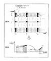
図7は、ある時刻における、各サブキャリアのSNR値を示す図である。また、図8は、各サブキャリアのSNR値と周波数特性の波形を示す図である。ここでは、平均SNR値は37[dB]である(ただし、小数点以下切り捨て)。なお、この例示においては10個のサブキャリアf1〜f10が用いられているが、サブキャリア数およびSNR値の取り得る範囲は限定されない。FIG. 7 is a diagram showing the SNR value of each subcarrier at a certain time. FIG. 8 is a diagram showing waveforms of SNR values and frequency characteristics of each subcarrier. Here, the average SNR value is 37 [dB] (however, the fractional part is rounded down). In this example, ten subcarriers f1 to f10 are used, but the range that the number of subcarriers and the SNR value can take is not limited.
サブキャリアf2〜f10に対応付けられた差分SNR値は、図9に示されている。また、図9には、サブキャリアf1のSNR値およびサブキャリアf2〜f10の差分SNR値の所要ビット数も示されている。さらに、図9には、サブキャリアf1〜f10の所要ビット数に対応する符号化範囲も示されている。The differential SNR values associated with the subcarriers f2 to f10 are shown in FIG. FIG. 9 also shows the required number of bits for the SNR value of subcarrier f1 and the differential SNR values of subcarriers f2 to f10 . Further, FIG. 9 also shows an encoding range corresponding to the required number of bits of subcarriers f1 to f10 .
具体的には、例えばサブキャリアf2のSNR値は、サブキャリアf1のSNR値よりも2[dB]だけ大きいため、サブキャリアf2の差分SNR値は2[dB]である。そして、飽和することなく差分SNR値「2」を符号化するには3ビットが必要である。ただし、ステップ幅を1dB/bitかつ2の補数と仮定する。3ビットでは、+3[dB]〜−4[dB]までの差分SNR値を符号化することができる。Specifically, for example, SNR values of the subcarrierf 2, since only 2 [dB] larger than the SNR value of the subcarriersf 1, the difference SNR values of subcarriersf 2 is 2 [dB]. Then, 3 bits are required to encode the differential SNR value “2” without saturation. However, the step width is assumed to be 1 dB / bit and 2's complement. With 3 bits, differential SNR values from +3 [dB] to -4 [dB] can be encoded.
ところで、ビット数制御部183では、平均SNR値をそのまま基準値として使用する、あるいは、基準値としての閾値を、平均SNR値から求める。閾値は、平均SNR値を引数とする関数によって算出される。例えば、2つの閾値Th1、Th2が用いられる場合、所定の2つのオフセット値(定数)をそれぞれ平均SNR値に加算することにより、閾値Th1、Th2を算出する。より具体的には、平均SNR値が37[dB]で、2つのオフセット値が「+3」「−3」の場合、閾値Th1は40[dB]となり、閾値Th2は34[dB]となる。前述のような基準値を用いることにより、差分SNR値の符号化を、より適切に制御することができる。By the way, the bit
また、ビット数制御部183では、ビット数制御を行うに際して、カウンタmが「1」であるか否かを判定する(ST1090)。 Further, the bit
カウンタmが「1」の場合(ST1090:YES)、固定のビット数、より具体的には、予め送受信間で既知のビット数が、サブキャリアf1のSNR値に割り当てられる(ST1100)。When counter m is “1” (ST1090: YES), a fixed number of bits, more specifically, a number of bits known in advance between transmission and reception is assigned to the SNR value of subcarrier f1 (ST1100).
一方、カウンタmが「1」でない場合(ST1090:NO)、可変のビット数が、サブキャリアfmの差分SNR値Xm’に割り当てられる(ST1110)。On the other hand, if counter m is not “1” (ST1090: NO), a variable number of bits is assigned to differential SNR value Xm ′ of subcarrier fm (ST1110).
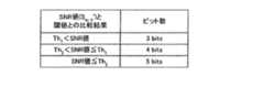
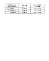
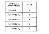
より具体的には、遅延部194から入力されるSNR値Sm−1’と閾値Th1、Th2との比較を行う。そして、その比較結果に従ってビット数を決定する。例えば、比較結果とビット数との対応関係を示すテーブル(図10)に従ってビット数が決定される。このテーブルにおいては、Th1<Sm−1’の場合、ビット数は「3」であり、Th2<Sm−1’≦Th1の場合、ビット数は「4」であり、Sm−1’≦Th2の場合、ビット数は「5」である。More specifically, the SNR value Sm−1 ′ input from the
ここで、比較結果(SNR値Sm−1’と基準値との比較結果)とビット数との対応関係について説明する。とりわけレイリーフェージングチャネルでは、SNR値の平均SNR値に対する相対的大きさ(SNR値対平均SNR値)と隣接サブキャリア間のSNR値の差(差分SNR値)との間には、図11に示すような性質がある。すなわち、SNR値対平均SNR値の増大に伴って差分SNR値は減少し、SNR値対平均SNR値の減少に伴って差分SNR値は増大する。したがって、ビット数制御部183では、符号化される差分SNR値に割り当てるビット数をSNR値対平均SNR値に対応付けて、差分SNR値に割り当てるビット数をSNR値対平均SNR値の増大に伴って減少させ、差分SNR値に割り当てるビット数をSNR値対平均SNR値の減少に伴って増加させる。Here, the correspondence between the comparison result (the comparison result between the SNR value Sm−1 ′ and the reference value) and the number of bits will be described. In particular, in the Rayleigh fading channel, the relative size of the SNR value with respect to the average SNR value (SNR value vs. average SNR value) and the difference between the SNR values between adjacent subcarriers (differential SNR value) are shown in FIG. There is such a property. That is, the differential SNR value decreases as the SNR value versus the average SNR value increases, and the differential SNR value increases as the SNR value versus the average SNR value decreases. Therefore, the number-of-
なお、図10のテーブルを用いる代わりに、関数を用いてビット数を算出しても良い。例えば、SNR値が対数値の場合は、SNR値から閾値Th1(または閾値Th2)を減算した結果からビット数を導出できるような関数を用いる。また、SNR値が真値の場合、SNR値を閾値Th1(または閾値Th2)で除算した結果からビット数を導出できるような関数を用いる。Note that the number of bits may be calculated using a function instead of using the table of FIG. For example, when the SNR value is a logarithmic value, a function that can derive the number of bits from the result of subtracting the threshold value Th1 (or threshold value Th2 ) from the SNR value is used. In addition, when the SNR value is a true value, a function that can derive the number of bits from the result of dividing the SNR value by the threshold Th1 (or threshold Th2 ) is used.
以上の処理によって各サブキャリアの差分SNR値(またはSNR値)に割り当てられるビット数は、図12に示されている。すなわち、サブキャリアf1のSNR値に割り当てられるビット数は固定値(本実施の形態では「6」)となり、サブキャリアf2〜f10の各々の差分SNR値に割り当てられるビット数は可変値となる。これらの割り当てビット数は符号化部195に通知される。The number of bits allocated to the differential SNR value (or SNR value) of each subcarrier by the above processing is shown in FIG. That is, the number of bits allocated to the SNR value of subcarrier f1 is a fixed value (“6” in the present embodiment), and the number of bits allocated to each differential SNR value of subcarriers f2 to f10 is variable. It becomes. The number of allocated bits is notified to the
サブキャリアf1のSNR値またはサブキャリアf2〜fMの差分SNR値X2’〜XM’のいずれかにビット数が割り当てられた後、符号化部195で、サブキャリアfmの差分SNR値Xm’に割り当てられたビット数を用いて、サブキャリアfmの差分SNR値Xm’が符号化される(ST1120)。あるいは、サブキャリアf1のSNR値に割り当てられたビット数を用いて、サブキャリアf1のSNR値が符号化される。After the number of bits is assigned toone of the SNR value of subcarrier f1 or the difference SNR values X2 ′ to XM ′ of subcarriers f2 to fM , the
そして、カウンタmがサブキャリア数M以上であるか否かが判定される(ST1130)。カウンタmがM未満の場合(ST1130:NO)、ステップST1140でカウンタmをm+1に更新してから、ステップST1040に戻る。カウンタmがM以上の場合h(ST1130:YES)、ステップST1150に進む。 Then, it is determined whether counter m is equal to or greater than the number of subcarriers M (ST1130). When counter m is less than M (ST1130: NO), counter m is updated to m + 1 in step ST1140, and then the process returns to step ST1040. If the counter m is greater than or equal to M, the process proceeds to step ST1150 (h) (ST1130: YES).
ステップST1150では、フィードバックフレーム生成部185で、符号化部195の出力(つまり、サブキャリアf1のSNR値およびサブキャリアf2〜fMの差分SNR値X2’〜XM’)および平均品質レベル算出部182の出力(平均SNR値)を用いて、CSIフレームが生成される。CSIフレーム生成後、時刻tkにおけるCSIフレーム生成部166の動作は終了となる。In step ST1150, the feedback
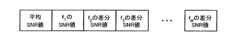
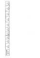
図13には、生成されるCSIフレームのフォーマットの一例が示されている。図13では、CSIフレームの先頭部に平均SNR値が配置され、平均SNR値に続いて、サブキャリアf1のSNR値が配置され、これに続いて、サブキャリア番号の小さい順にサブキャリアf2〜fMの差分SNR値が配置される。FIG. 13 shows an example of the format of the generated CSI frame. In Figure 13, it is arranged an average SNR value at the beginning of the CSI frame, following the average SNR value is arranged SNR values of subcarriers f1 is, following this, the subcarrier f2 in ascending order of subcarrier numbers ˜fM differential SNR values are arranged.
なお、図13に示すフレームフォーマットを使用する代わりに、図14に示すフレームフォーマットを使用しても良い。図14では、平均SNR値に続いて、サブキャリアf1のSNR値と平均SNR値との差が配置される。これに続いて、サブキャリア番号の小さい順にサブキャリアf2〜fMの差分SNR値が配置される。このフレームフォーマットが採用される場合、CSIフレーム生成部166では、サブキャリアf1のSNR値から平均SNR値を減算する処理が行われる一方、CSIフレーム処理部110では、サブキャリアf1のSNR値と平均SNR値との差に平均SNR値を加算する処理が行われる。Instead of using the frame format shown in FIG. 13, the frame format shown in FIG. 14 may be used. In FIG. 14, following the average SNR value, the difference between the SNR value of subcarrier f1 and the average SNR value is arranged. Following this, the differential SNR values of subcarriers f2 to fM are arranged in ascending order of subcarrier number. When this frame format is adopted, the CSI
平均SNR値から導出される閾値Th1、Th2がビット数制御において用いられる場合は、例えば図15に示すフォーマットのCSIフレームが生成される。図15では、CSIフレームの先頭部に閾値Th1、Th2が順次配置される。閾値Th1、Th2に続いて、サブキャリアf1のSNR値が配置され、これに続いて、サブキャリア番号の小さい順にサブキャリアf2〜fMの差分SNR値が配置される。When threshold values Th1 and Th2 derived from the average SNR value are used in the bit number control, for example, a CSI frame having the format shown in FIG. 15 is generated. In FIG. 15, threshold values Th1 and Th2 are sequentially arranged at the head of the CSI frame. Subsequent to the thresholds Th1 and Th2 , the SNR value of the subcarrier f1 is arranged, and subsequently, the differential SNR values of the subcarriers f2 to fM are arranged in ascending order of the subcarrier number.
なお、図15に示すフレームフォーマットを使用する代わりに、図16に示すフレームフォーマットを使用しても良い。図16では、CSIフレームの先頭部に閾値Th1が配置され、これに続いて、閾値Th1と閾値Th2との差が配置される。これに続いて、サブキャリアf1のSNR値が配置され、これに続いて、サブキャリア番号の小さい順にサブキャリアf2〜fMの差分SNR値が配置される。この場合、CSIフレーム生成部166では、閾値Th2から閾値Th1を減算する処理が行われる一方、CSIフレーム処理部110では、閾値Th1と閾値Th2との差に閾値Th1を加算する処理が行われる。Instead of using the frame format shown in FIG. 15, the frame format shown in FIG. 16 may be used. In FIG. 16, threshold Th1 is arranged at the head of the CSI frame, and subsequently, the difference between threshold Th1 and threshold Th2 is arranged. Subsequently, the SNR value of subcarrier f1 is arranged, and subsequently, the differential SNR values of subcarriers f2 to fM are arranged in ascending order of subcarrier numbers. In this case, the CSI
なお、フレームフォーマットは上記のものだけに限定されない。例えば、平均SNR値がCSIフレームの末尾に付加されるフレームフォーマットを採用しても良い。または、サブキャリア番号の大きい順に差分SNR値あるいはSNR値が配置されるフレームフォーマットを採用しても良い。送受信間で共通に規定された配置順序を有するものであれば、任意のフレームフォーマットを採用することができる。 The frame format is not limited to the above. For example, a frame format in which the average SNR value is added to the end of the CSI frame may be adopted. Alternatively, a frame format in which differential SNR values or SNR values are arranged in descending order of subcarrier numbers may be adopted. Any frame format can be adopted as long as it has an arrangement order defined in common between transmission and reception.
前述の動作例において割り当てられたビット数で符号化されたSNR値または差分SNR値を用いて、図10のフレームフォーマットを有するCSIフレームを生成した場合、図17に示すように、平均SNR値は6ビットで示され、サブキャリアf1のSNR値は6ビットで示され、サブキャリアf2の差分SNR値は4ビットで示され、サブキャリアf3の差分SNR値は3ビットで示され、サブキャリアf4の差分SNR値は3ビットで示され、サブキャリアf5の差分SNR値は4ビットで示され、サブキャリアf6の差分SNR値は5ビットで示され、サブキャリアf7の差分SNR値は5ビットで示され、サブキャリアf8の差分SNR値は5ビットで示され、サブキャリアf9の差分SNR値は5ビットで示され、サブキャリアf10の差分SNR値は4ビットで示される。When the CSI frame having the frame format of FIG. 10 is generated using the SNR value or the differential SNR value encoded with the allocated number of bits in the above operation example, the average SNR value is as shown in FIG. 6 bits, the SNR value of subcarrier f1 is indicated by 6 bits, the differential SNR value of subcarrier f2 is indicated by 4 bits, the differential SNR value of subcarrier f3 is indicated by 3 bits, The differential SNR value of subcarrier f4 is indicated by 3 bits, the differential SNR value of subcarrier f5 is indicated by 4 bits, the differential SNR value of subcarrier f6 is indicated by 5 bits, and subcarrier f7 differential SNR value is indicated by 5 bits, the difference SNR value of subcarrierf 8 is indicated by 5 bits, the difference SNR values of subcarriersf 9 is indicated by 5 bits, sub Difference SNR value of Yariaf 10 is represented by 4 bits.
次いで、CSIフレーム処理部110の内部構成およびその動作について説明する。CSIフレーム処理部110は、図18に示すように、フィードバックフレーム処理部130、ビット数制御部131、復号化部132、ビット変換部133、加算部134、遅延部135および回線状態メモリ部136を有する。 Next, the internal configuration and operation of the CSI
取得手段としてのフィードバックフレーム処理部130は、受信装置150から送られるCSIフレームを取得する。また、CSIフレームから基準値(本実施の形態では、平均SNR値)を抽出してビット数制御部131へ出力する。ただし、平均SNR値が抽出されるのは、例えば図13のCSIフレームが用いられる場合である。例えば図15のCSIフレームが用いられる場合は、閾値Th1、Th2が抽出される。CSIフレームのその他の部分は復号化部132へ出力される。The feedback
復号化制御手段としてのビット数制御部131は、フィードバックフレーム処理部130および遅延部135からの入力を受け、サブキャリア毎のSNR値の平均SNR値に対する相対的大きさに基づいて、復号化部132での復号化に用いるビット数を制御する。換言すれば、復号化部132で復号される差分SNR値に可変のビット数を割り当てる。割り当てられたビット数は、復号化部132に通知される。 The bit
復号化部132は、ビット数制御部131から通知されたビット数に従って、フィードバックフレーム処理部130から入力されたCSIフレーム(平均SNR値以外の部分)をサブキャリア毎の差分SNR値(またはSNR値)に分割することによって、サブキャリア毎の差分SNR値(またはSNR値)を復号する。 The
ビット変換部133は、復号された差分SNR値(またはSNR値)のステップ幅を変換する。この変換により、差分SNR値(またはSNR値)のステップ幅を、量子化部191の量子化に用いられたステップ幅から、加算部134の加算に用いるステップ幅に合わせる。 The
加算部134は、ビット変換部133の出力と遅延部135の出力とを加算する。この加算によって得られたサブキャリア毎のSNR値は、遅延部135および回線状態メモリ部136に出力される。ただし、サブキャリアf1のSNR値はそのまま遅延部135および回線状態メモリ部136に出力される。The
遅延部135は、内部の状態値を、加算部134の出力で更新する。そして、更新された状態値を1サブキャリア分だけ遅延して、加算部134およびビット数制御部131に出力する。 The
回線状態メモリ部136は、加算部134から入力されたサブキャリア毎のSNR値を保持する。保持されたSNR値は、サブキャリア毎のCSIとして変調パラメータ決定部111に出力される。 The line
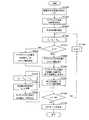
続いて、CSIフレーム処理部110における動作の一例について説明する。図19には、CSIフレーム処理部110の動作例を説明するためのフロー図が示されている。 Subsequently, an example of the operation in the CSI
まず、遅延部135の状態値が「0」に初期化されるとともに、カウンタmが「1」に初期化される(ST1510)。 First, the state value of
そして、フィードバックフレーム処理部130で、CSIフレームから平均SNR値を抽出する(ST1520)。そして、カウンタmが「1」であるか否かが判定される(ST1530)。 Then, feedback
カウンタmが「1」の場合(ST1530:YES)、固定のビット数、より具体的には、予め送受信間で既知のビット数が、サブキャリアf1のSNR値に割り当てられる(ST1540)。If the counter m is "1" (ST1530: YES), a fixed number of bits, more specifically, a known number of bits in advance between transmission and reception, is allocated to the SNR value of subcarrierf 1 (ST1540).
一方、カウンタmが「1」でない場合(ST1530:NO)、可変のビット数が、サブキャリアfmの差分SNR値Xm’に割り当てられる(ST1550)。可変ビット数割り当ての具体的な動作は、CSIフレーム生成部166のビット数制御部183と同一である。On the other hand, when counter m is not “1” (ST1530: NO), a variable number of bits is assigned to differential SNR value Xm ′ of subcarrier fm (ST1550). The specific operation of variable bit number allocation is the same as that of the bit
そして、サブキャリアf1のSNR値またはサブキャリアf2〜fMの差分SNR値X2’〜XM’のいずれかにビット数が割り当てられた後、復号化部132で、サブキャリアfmの差分SNR値Xm’に割り当てられたビット数を用いて、サブキャリアfmの差分SNR値Xm’が復号される(ST1560)。あるいは、サブキャリアf1のSNR値に割り当てられたビット数を用いて、サブキャリアf1のSNR値が復号される。Then, after the number of bits is assigned toone of the SNR value of subcarrier f1 or the difference SNR values X2 ′ to XM ′ of subcarriers f2 to fM , decoding
そして、ビット変換部133で、復号後の差分SNR値(またはSNR値)のステップ幅を変換する(ST1570)。変換後のステップ幅は、加算部134で用いられるステップ幅に合わせられる。変換前のステップ幅は図6Bに示されたSSbであり、変換後のステップ幅は図6Cに示されたSSaである。ここで、ビット変換部133で量子化誤差が発生しなければ、必ずしも変換後のステップ幅は図6Cで示されたSSaである必要はない。 Then,
変換後の差分SNR値Xm’は、加算部134で、遅延部135の出力であるm−1番目のサブキャリアfm−1のSNR値Sm−1’に加算される(ST1580)。加算結果は、m番目のサブキャリアfmのSNR値Sm’として遅延部135および回線状態メモリ部136に出力される。なお、サブキャリアf1のSNR値はそのまま加算部134から遅延部135および回線状態メモリ部136に出力される。そして、遅延部135の状態値がSNR値Sm’に更新される(ST1590)。また、回線状態メモリ部136では、SNR値Sm’が保持される(ST1600)。Difference SNR value Xm ′ after conversion is added by
そして、カウンタmがサブキャリア数M以上であるか否かが判定される(ST1610)。カウンタmがM未満の場合(ST1610:NO)、ステップST1620でカウンタmをm+1に更新してから、ステップST1530に戻る。カウンタmがM以上の場合h(ST1610:YES)、時刻tkにおけるCSIフレーム処理部110の動作が終了となる。Then, it is determined whether or not the counter m is equal to or greater than the number of subcarriers M (ST1610). If counter m is less than M (ST1610: NO), counter m is updated to m + 1 in step ST1620, and then the process returns to step ST1530. If the counter m is equal to or greater than M h (ST1610: YES), the operation of CSI
このように、本実施の形態によれば、受信装置150においては、あるサブキャリアのSNR値(第1のSNR値)とそのサブキャリアに隣接するサブキャリアのSNR値(第2のSNR値)との差分値(差分SNR値)に割り当てるビット数を、第2のSNR値の平均SNR値に対する相対的大きさに対応付けることにより、差分SNR値が取り得る範囲(ダイナミックレンジ)に応じた最小限のビット数を割り当てることができるだけでなく、複数の異なる差分SNR値に複数の異なるビット数を割り当てても、その割り当てについての情報をサイド情報として付加することなくCSIフレームを生成することができるため、フィードバック情報の品質を維持しつつ、フィードバック情報のデータ量を削減することができる。 As described above, according to the present embodiment, in receiving
また、本実施の形態によれば、送信装置100においては、第1のSNR値と第2のSNR値との差分値に割り当てるビット数を、第2のSNR値の平均SNR値に対する相対的大きさに対応付けることにより、ダイナミックレンジに応じた最小限のビット数を割り当てることができるだけでなく、複数の異なる差分SNR値に複数の異なるビット数を割り当てても、その割り当てについての情報をサイド情報として参照することなくCSIフレームを復元することができるため、フィードバック情報の品質を維持しつつ、フィードバック情報のデータ量を削減することができる。 Further, according to the present embodiment, in
(実施の形態2)
図20は、本発明の実施の形態2に係る受信装置に設けられたCSIフレーム生成部166の構成を示すブロック図である。なお、本実施の形態の受信装置は、実施の形態1で説明した受信装置150と同様の基本的構成を有する。よって、実施の形態1で説明したものと同一のまたは同様の構成要素には同一の参照符号を付す。以下の説明では、主に実施の形態1との相違点について記載する。(Embodiment 2)
FIG. 20 is a block diagram showing a configuration of CSI
図20のCSIフレーム生成部166は、実施の形態1で説明したビット数制御部183の代わりにステップ幅制御部201を有する。 The CSI
符号化制御手段としてのステップ幅制御部201は、サブキャリア毎のSNR値の平均SNR値に対する相対的大きさに基づいて、量子化部191での量子化に用いるステップ幅を可変設定することにより、DPCM部184の符号化処理を制御する。ここで、ステップ幅は、1ビットあたりの振幅の大きさであり、すなわち、1ビットで示されるSNR値の大きさである。換言すれば、量子化後の差分SNR値に対して可変のステップ幅を設定する。つまり、図6Bに示された量子化のステップ幅SSbが可変に設定される。設定されたステップ幅は、量子化部191およびビット変換部192に通知される。 The step
したがって、本実施の形態の量子化部191は、実施の形態1で説明した量子化処理を、ステップ幅制御部201から通知されたステップ幅を用いて行う。また、本実施の形態のビット変換部192は、実施の形態1で説明したステップ幅変換を、ステップ幅制御部201から通知されたステップ幅を用いて行う。また、本実施の形態の符号化部195は、実施の形態1で説明した符号化処理を、予め設定された固定のビット数を用いて行う。 Therefore, the
続いて、CSIフレーム生成部166における動作の一例について説明する。図21には、CSIフレーム生成部166の動作例を説明するためのフロー図が示されている。なお、送受信局間でやりとりするOFDMフレームの構成、伝送路応答推定タイミングおよび周波数応答推定値については、図5Aおよび図5Bに示されたものが用いられるものとする。また、図21において、実施の形態1で図4を用いて説明したものと同一の処理については、同一の参照番号を付し、その詳細な説明を省略する。 Next, an example of the operation in the CSI
ステップST1040に続いて、ステップST2010では、ステップ幅制御部201で、カウンタmが「1」であるか否かが判定される。 Subsequent to step ST1040, in step ST2010, the step
カウンタmが「1」の場合(ST2010:YES)、サブキャリアf1のSNR値について予め設定されている固定のステップ幅、より具体的には、予め送受信間で既知のステップ幅が出力される(ST2020)。When counter m is “1” (ST2010: YES), a fixed step width set in advance for the SNR value of subcarrier f1 , more specifically, a known step width between transmission and reception is output in advance. (ST2020).
一方、カウンタmが「1」でない場合(ST2010:NO)、サブキャリアfmの差分SNR値Xm’に対して、可変のステップ幅が設定される(ST2030)。On the other hand, if counter m is not “1” (ST2010: NO), a variable step width is set for differential SNR value Xm ′ of subcarrier fm (ST2030).
より具体的には、遅延部194から入力されるSNR値Sm−1’と基準値(閾値)との比較を行う。実施の形態1で説明した閾値Th1、Th2が用いられる場合は、SNR値Sm−1’と閾値Th1、Th2との比較を行う。そして、その比較結果に従ってステップ幅を決定する。例えば、比較結果とステップ幅との対応関係を示すテーブル(図22)に従ってステップ幅を決定する。このテーブルにおいては、Th1<Sm−1’の場合、ステップ幅は「0.5dB/bit」であり、Th2<Sm−1’≦Th1の場合、ステップ幅は「1.0dB/bit」であり、Sm−1’≦Th2の場合、ステップ幅は「2.0dB/bit」である。More specifically, the SNR value Sm−1 ′ input from the
ここで、比較結果(SNR値Sm−1’と基準値との比較結果)とステップ幅との対応関係について説明する。とりわけレイリーフェージングチャネルでは、SNR値対平均SNR値の増大に伴って差分SNR値は減少し、SNR値対平均SNR値の減少に伴って差分SNR値は増大する、という性質がある(図11)。したがって、ステップ幅制御部201では、量子化に用いられるステップ幅をSNR値対平均SNR値に対応付けて、量子化のステップ幅をSNR値対平均SNR値の増大に伴って縮小させ、量子化のステップ幅をSNR値対平均SNR値の減少に伴って拡大させる。Here, the correspondence relationship between the comparison result (the comparison result between the SNR value Sm−1 ′ and the reference value) and the step width will be described. In particular, in the Rayleigh fading channel, the difference SNR value decreases as the SNR value versus the average SNR value increases, and the difference SNR value increases as the SNR value versus the average SNR value decreases (FIG. 11). . Accordingly, the step
なお、図22のテーブルを用いる代わりに、関数を用いてステップ幅を算出しても良い。例えば、SNR値が対数値の場合は、SNR値から閾値Th1(または閾値Th2)を減算した結果からステップ幅を導出できるような関数を用いる。また、SNR値が真値の場合、SNR値を閾値Th1(または閾値Th2)で除算した結果からステップ幅を導出できるような関数を用いる。Note that the step width may be calculated using a function instead of using the table of FIG. For example, when the SNR value is a logarithmic value, a function that can derive the step width from the result of subtracting the threshold value Th1 (or threshold value Th2 ) from the SNR value is used. Further, when the SNR value is a true value, a function that can derive the step width from the result obtained by dividing the SNR value by the threshold Th1 (or the threshold Th2 ) is used.
図7および図8に示されたSNR値および周波数特性を前提とした場合、各サブキャリアの差分SNR値(またはSNR値)の量子化に対して設定されるステップ幅は、図23に示されたとおりとなる。すなわち、サブキャリアf1のSNR値の量子化に用いられるステップ幅は固定値(本実施の形態では「1dB/bit」)となり、サブキャリアf2〜f10の各々の差分SNR値の量子化に用いられるステップ幅は可変値となる。これらのステップ幅は量子化部191およびビット変換部192に通知される。Given the SNR values and frequency characteristics shown in FIG. 7 and FIG. 8, the step width set for the quantization of the differential SNR value (or SNR value) of each subcarrier is shown in FIG. It will be true. That is, the step width used for the quantization of the SNR value of subcarrier f1 is a fixed value (“1 dB / bit” in the present embodiment), and the differential SNR value of each of subcarriers f2 to f10 is quantized. The step width used for is a variable value. These step widths are notified to the
サブキャリアf1のSNR値またはサブキャリアf2〜fMの差分SNR値X2’〜XM’のいずれかについてステップ幅が設定された後、量子化部191で、サブキャリアfmの差分SNR値Xm’について設定されたステップ幅を用いて、サブキャリアfmの差分SNR値Xm’が量子化される(ST2040)。あるいは、サブキャリアf1のSNR値について設定されたステップ幅を用いて、サブキャリアf1のSNR値が量子化される。具体的には、図23に示すように、サブキャリアf1のSNR値は、1dB/bitのステップ幅で量子化され、サブキャリアf2の差分SNR値は、1dB/bitのステップ幅で量子化され、サブキャリアf3の差分SNR値は、0.5dB/bitのステップ幅で量子化され、サブキャリアf4の差分SNR値は、0.5dB/bitのステップ幅で量子化され、サブキャリアf5の差分SNR値は、1dB/bitのステップ幅で量子化され、サブキャリアf6の差分SNR値は、2dB/bitのステップ幅で量子化され、サブキャリアf7の差分SNR値は、2dB/bitのステップ幅で量子化され、サブキャリアf8の差分SNR値は、2dB/bitのステップ幅で量子化され、サブキャリアf9の差分SNR値は、2dB/bitのステップ幅で量子化され、サブキャリアf10の差分SNR値は、1dB/bitのステップ幅で量子化される。After the step width is set for any of the SNR value of the subcarrier f1 or the difference SNR values X2 ′ to XM ′ of the subcarriers f2 to fM , the
そして、ビット変換部192では、ステップ幅制御部201から通知されたステップ幅に基づいて、量子化後の差分SNR値Xm’(またはSNR値)のステップ幅を変換する(ST2050)。変換後のステップ幅は、図6Cに示すように、SSaである。つまり、この変換により、差分SNR値Xm’(またはSNR値)は、減算部190、加算部193および遅延部194で用いられるステップ幅およびビット数で再び表現される。ステップST2050の後、実施の形態1で説明したステップST1070、ST1080に続いて、ステップST2060の処理が実行される。Then,
ステップST2060では、符号化部195で、サブキャリアfmの差分SNR値Xm’に対して予め設定されているビット数を用いて、サブキャリアfmの差分SNR値Xm’が符号化される。あるいは、サブキャリアf1のSNR値に対して予め設定されているビット数を用いて、サブキャリアf1のSNR値が符号化される。本実施の形態では、サブキャリアf1のSNR値は、6ビットで符号化され、サブキャリアf2〜fMの各々の差分SNR値は、4ビットで符号化される。In step ST 2060, the
本実施の形態のCSIフレーム生成部166では、差分SNR値が相対的に小さい領域(サブキャリア)に対しては、ステップ幅を小さく設定することにより量子化誤差を低減させ、一方、差分SNR値が相対的に大きい領域(サブキャリア)に対しては、ステップ幅を大きく設定することによりダイナミックレンジを大きくして飽和による誤差を低減させる。したがって、同数の符号化ビットの使用を前提として、常に固定の量子化ステップ幅を用いる従来のDPCMと本実施の形態のDPCMとを比較すると、本実施の形態のDPCMの方が、符号化による波形歪が小さくなる。換言すれば、従来のDPCMで本実施の形態のDPCMと同程度の歪レベルを実現するためには、本実施の形態のDPCMの符号化で用いるビット数よりも多くのビット数が必要となる。すなわち、本実施の形態のDPCMは、フィードバック情報の品質を維持しつつ、フィードバック情報のデータ量を削減することができる。 In the CSI
次いで、本実施の形態に係る送信装置に設けられたCSIフレーム処理部110について、図24を用いて説明する。なお、本実施の形態の送信装置は、実施の形態1で説明した送信装置100と同様の基本的構成を有する。よって、実施の形態1で説明したものと同一のまたは同様の構成要素には同一の参照符号を付す。以下の説明では、主に実施の形態1との相違点について記載する。 Next, CSI
図24に示すCSIフレーム処理部110は、実施の形態1で説明したビット数制御部131の代わりにステップ幅制御部202を有する。 A CSI
復号化制御手段としてのステップ幅制御部202は、フィードバックフレーム処理部130および遅延部135からの入力を受け、サブキャリア毎のSNR値の平均SNR値に対する相対的大きさに基づいて、ビット変換部133でのステップ幅変換に用いるステップ幅を可変設定することにより、差分SNR値(またはSNR値)の復号化処理を制御する。換言すれば、ステップ幅変換を施される差分SNR値(またはSNR値)のステップ幅を可変設定する。設定されたステップ幅は、ビット変換部133に通知される。 The step
ビット変換部133は、ステップ幅制御部202から通知されたステップ幅に従って、復号された差分SNR値(またはSNR値)のステップ幅を変換する。この変換により、差分SNR値(またはSNR値)のステップ幅を、量子化部191の量子化に用いられたステップ幅から、加算部134の加算に用いられるステップ幅に合わせる。 The
なお、本実施の形態では、復号化部132は、予め設定されたビット数に従って、フィードバックフレーム処理部130から入力されたCSIフレーム(平均SNR値以外の部分)をサブキャリア毎の差分SNR値(またはSNR値)に分割することによって、サブキャリア毎の差分SNR値(またはSNR値)を復号する。 In the present embodiment, decoding
次いで、CSIフレーム処理部110における動作について説明する。図25は、CSIフレーム処理部110の動作例を説明するためのフロー図である。なお、図25において、実施の形態1で図19を用いて説明したものと同一の処理については、同一の参照番号を付し、その詳細な説明を省略する。 Next, the operation in the CSI
カウンタmが「1」の場合(ST1530:YES)、サブキャリアf1のSNR値について予め設定されている固定のステップ幅、より具体的には、予め送受信間で既知のステップ幅が出力される(ST2510)。When the counter m is “1” (ST1530: YES), a fixed step width preset for the SNR value of the subcarrier f1 , more specifically, a known step width between transmission and reception is output in advance. (ST2510).
一方、カウンタmが「1」でない場合(ST1530:NO)、サブキャリアfmの差分SNR値Xm’に対して、可変のステップ幅が設定される(ST2520)。可変ステップ幅設定の具体的な動作は、CSIフレーム生成部166のステップ幅制御部201と同一である。On the other hand, when counter m is not “1” (ST1530: NO), a variable step width is set for differential SNR value Xm ′ of subcarrier fm (ST2520). The specific operation of setting the variable step width is the same as that of the step
そして、サブキャリアf1のSNR値またはサブキャリアf2〜fMの差分SNR値X2’〜Xm’のいずれかに対してステップ幅が設定された後、復号化部132で、サブキャリアfmの差分SNR値Xm’に対して予め設定された固定のビット数を用いて、サブキャリアfmの差分SNR値Xm’が復号される(ST2530)。あるいは、サブキャリアf1のSNR値に対して予め設定された固定のビット数を用いて、サブキャリアf1のSNR値が復号される。Then, after a step width is set for any of the SNR value of subcarrier f1 or the differential SNR values X2 ′ to Xm ′ of subcarriers f2 to fM , decoding
そして、ビット変換部133で、復号後の差分SNR値(またはSNR値)のステップ幅を、ステップ幅制御部202から通知されたステップ幅に基づいて変換する(ST2540)。変換後のステップ幅は、加算部134で用いられるステップ幅に合わせられる。変換前のステップ幅は図6Bに示されたSSbである、つまり、量子化部191の量子化に用いられたステップ幅と同一である。一方、変換後のステップ幅は図6Cに示されたSSaである。ステップST2540に続いて、実施の形態1で説明したステップST1580に進む。ここで、ビット変換部133で量子化誤差が発生しなければ、必ずしも変換後のステップ幅は図6Cで示されたSSaである必要はない。 Then,
このように、本実施の形態によれば、受信装置においては、第1のSNR値と第2のSNR値との差分値、つまり差分SNR値の量子化のステップ幅を、第2のSNR値の平均SNR値に対する相対的大きさに対応付けることにより、ダイナミックレンジに応じた最小限のステップ幅を設定することができるだけでなく、複数の異なる差分SNR値に複数の異なるステップ幅を設定しても、その設定についての情報をサイド情報として付加することなくCSIフレームを生成することができるため、フィードバック情報の品質を維持しつつ、フィードバック情報のデータ量を削減することができる。 Thus, according to the present embodiment, in the receiving apparatus, the difference value between the first SNR value and the second SNR value, that is, the quantization step width of the difference SNR value is set to the second SNR value. By associating with the relative magnitude with respect to the average SNR value, it is possible not only to set a minimum step width according to the dynamic range, but also to set a plurality of different step widths to a plurality of different differential SNR values. Since the CSI frame can be generated without adding information about the setting as side information, the data amount of the feedback information can be reduced while maintaining the quality of the feedback information.
また、本実施の形態によれば、送信装置においては、第1のSNR値と第2のSNR値との差分値、つまり差分SNR値の量子化のステップ幅を、第2のSNR値の平均SNR値に対する相対的大きさに対応付けることにより、ダイナミックレンジに応じた最小限のステップ幅を設定することができるだけでなく、複数の異なる差分SNR値に複数の異なるステップ幅を設定しても、その設定についての情報をサイド情報として参照することなくCSIフレームを復元することができるため、フィードバック情報の品質を維持しつつ、フィードバック情報のデータ量を削減することができる。 Also, according to the present embodiment, in the transmission apparatus, the difference value between the first SNR value and the second SNR value, that is, the quantization step width of the difference SNR value is set to the average of the second SNR values. By associating with the relative size with respect to the SNR value, it is possible not only to set a minimum step width according to the dynamic range, but also to set a plurality of different step widths to a plurality of different differential SNR values. Since the CSI frame can be restored without referring to the setting information as side information, the data amount of the feedback information can be reduced while maintaining the quality of the feedback information.
なお、本実施の形態で説明したステップ幅制御部201を実施の形態1で説明したCSIフレーム生成部166に設けるとともに、本実施の形態で説明したステップ幅制御部202を実施の形態1で説明したCSIフレーム処理部110に設けた場合、符号化のビット数および量子化のステップ幅のいずれか一方または双方を可変設定することができる。 The step
(実施の形態3)
図26は、本発明の実施の形態3に係る受信装置に設けられたCSIフレーム生成部166の構成を示すブロック図である。なお、本実施の形態の受信装置は、実施の形態1で説明した受信装置150と同様の基本的構成を有する。よって、実施の形態1で説明したものと同一のまたは同様の構成要素については同一の参照符号を付す。以下の説明では、主に実施の形態1との相違点について説明する。(Embodiment 3)
FIG. 26 is a block diagram showing a configuration of CSI
図26のCSIフレーム生成部166は、遅延分散測定部301をさらに有する。 The CSI
遅延分散推定部301は、伝送路応答推定部165で得られた伝送路応答推定値を用いて、伝送路の遅延分散を推定する。この推定の結果として、遅延分散推定値を得る。遅延分散推定値は、ビット数制御部183およびフィードバックフレーム生成部185に出力される。 The delay
したがって、本実施の形態のビット数制御部183は、実施の形態1で説明したビット数設定を、遅延分散推定値にも基づいて行う。また、本実施の形態のフィードバックフレーム生成部185は、実施の形態1で説明したCSIフレーム生成を、遅延分散推定値も用いて行う。 Therefore, the bit
次いで、CSIフレーム生成部166における動作について説明する。 Next, the operation in the CSI
遅延分散推定部301では、伝送路応答推定部165で算出された伝送路の周波数応答値である伝送路応答推定値を用いて、伝送路の遅延分散推定値の算出を行う。 The delay
伝送路応答の遅延分散を推定する方法は特定のものに限定されないが、以下にその例を挙げる。 The method for estimating the delay dispersion of the transmission line response is not limited to a specific method, but an example is given below.
例えば、図27に示すように、伝送路の周波数応答のSNR特性(振幅特性でも良い)に対して、ある閾値を設定する。そして、その閾値を上から下に交差する回数(以下「レベル交差回数」と言う)から、単位周波数あたりの変動の激しさを検出する。レベル交差回数が多い場合、伝送路応答の周波数相関つまり隣接サブキャリア間相関が低い。逆にレベル交差回数が少ない場合は、隣接サブキャリア間相関が高い。したがって、図28に示すように、遅延分散が大きければ周波数相関が低く(つまり差分SNR値が大きい)且つ遅延分散が小さければ周波数相関が大きい(つまり差分SNR値が小さい)関係にあるため、レベル交差回数から遅延分散の大きさを推定することができる。 For example, as shown in FIG. 27, a certain threshold is set for the SNR characteristic (or the amplitude characteristic) of the frequency response of the transmission path. Then, the intensity of fluctuation per unit frequency is detected from the number of times that the threshold is crossed from the top to the bottom (hereinafter referred to as “level crossing number”). When the number of level crossings is large, the frequency correlation of the transmission line response, that is, the correlation between adjacent subcarriers is low. Conversely, when the number of level crossings is small, the correlation between adjacent subcarriers is high. Therefore, as shown in FIG. 28, since the frequency correlation is low (that is, the differential SNR value is large) if the delay dispersion is large and the frequency correlation is large (that is, the differential SNR value is small) if the delay dispersion is small, The magnitude of the delay dispersion can be estimated from the number of crossings.
また、他の例では、図29Aおよび図29Bに示すように、伝送路の周波数応答(図29A)をフーリエ変換によって時間領域(図29B)に変換することにより、伝送路のインパルス応答を得ることができる。得られたインパルス応答から遅延分散を算出しても良い。或いは、このインパルス応答を時間平均して得られる遅延プロファイルから遅延分散を算出しても良い。伝搬環境が著しく変化しない範囲であれば時間平均した遅延プロファイルを用いた方が、より精度良く遅延分散を推定することができる。 In another example, as shown in FIGS. 29A and 29B, the impulse response of the transmission line is obtained by converting the frequency response of the transmission line (FIG. 29A) to the time domain (FIG. 29B) by Fourier transform. Can do. The delay dispersion may be calculated from the obtained impulse response. Alternatively, the delay dispersion may be calculated from a delay profile obtained by averaging the impulse responses over time. If the propagation environment does not change significantly, it is possible to estimate the delay dispersion with higher accuracy by using the time-averaged delay profile.
図29Aおよび図29Bに示した例では、周波数応答を推定する方法を用いて遅延プロファイルを求めたが、遅延プロファイルの生成方法はこれに限定されない。例えば、パイロット信号などの受信結果を利用し時間領域で直接的にインパルス応答を求めても良い。 In the example shown in FIGS. 29A and 29B, the delay profile is obtained using the method of estimating the frequency response, but the method of generating the delay profile is not limited to this. For example, an impulse response may be obtained directly in the time domain using a reception result such as a pilot signal.
遅延分散推定部301では、例えば図30に示すようなテーブルを参照し、検出されたレベル交差回数NLに対応する遅延分散推定値を取得する。そして、取得した遅延分散推定値をビット数制御部183に出力する。The delay
ビット数制御部183では、遅延分散推定値の増大に伴ってビット数を増加させ、遅延分散推定値の減少に伴ってビット数を減少させる。 The bit
具体的には、ビット数制御部183では、遅延分散推定部301より入力される遅延分散推定値の大きさに応じて、テーブルの設定値を切り替える。より具体的には、図31に示すように、入力された遅延分散推定値に対応するテーブルを選択する。 Specifically, the bit
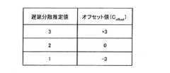
なお、遅延分散推定からテーブル選択までの制御方法は、上記のものだけに限定されない。例えば、ビット数制御部183では、遅延分散推定部301から出力されたレベル交差回数NLに対して、基準値(閾値)の算出に用いるオフセット値Coffsetを、例えば図32に示すテーブルから選択する。そして、選択されたオフセット値Coffsetを例えば次の式(4)〜(7)に代入することにより閾値Th1、Th2、Th3、Th4を算出する。この場合、可変ビット数設定には、例えば図33に示すテーブルが用いられる。
Th1=平均SNR値+ 5+Coffset …(4)
Th2=平均SNR値 +Coffset …(5)
Th3=平均SNR値− 5+Coffset …(6)
Th4=平均SNR値−10+Coffset …(7)Note that the control method from delay dispersion estimation to table selection is not limited to the above. For example, the bit
Th1 = average SNR value + 5 + Coffset (4)
Th2 = average SNR value + Coffset (5)
Th3 = average SNR value−5 + Coffset (6)
Th4 = average SNR value−10 + Coffset (7)
また、さらに別の制御方法を用いても良い。例えば、m番目のサブキャリアfmの差分SNR値Xm’に対して設定されるビット数を、平均SNR値、SNR値Sm−1’および遅延分散推定値を引数とする関数を用いて算出しても良い。Still another control method may be used. For example, the number of bits set for the differential SNR value Xm ′ of the m-th subcarrier fm is calculated using a function that uses the average SNR value, the SNR value Sm−1 ′, and the delay variance estimated value as arguments. It may be calculated.
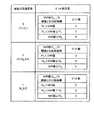
フィードバックフレーム生成部185では、例えば図34、図35、図36、図37に示すようなフォーマットのCSIフレームが生成される。図34のCSIフレームは、図13のCSIフレームと同様のフォーマットを有するが、その最先頭部には遅延分散推定値が配置されている。図35のCSIフレームは、図14のCSIフレームと同様のフォーマットを有するが、その最先頭部には遅延分散推定値が配置されている。図36のCSIフレームは、図15のCSIフレームと同様のフォーマットを有するが、その最先頭部には遅延分散推定値が配置されている。図37のCSIフレームは、図16のCSIフレームと同様のフォーマットを有するが、その最先頭部には遅延分散推定値が配置されている。なお、遅延分散推定値は必ずしもCSIフレームの最先頭部に配置されなくても良い。送受信間で共通に規定された配置順序を有するものであれば、任意のフレームフォーマットを採用することができる。 The feedback
次いで、本実施の形態に係る送信装置に設けられたCSIフレーム処理部110について、図38を用いて説明する。なお、本実施の形態の送信装置は、実施の形態1で説明した送信装置100と同様の基本的構成を有する。よって、実施の形態で説明したものと同一のまたは同様の構成要素には同一の参照符号を付す。以下の説明では、主に実施の形態1との相違点について記載する。 Next, CSI
図38に示すCSIフレーム処理部110において、フィードバックフレーム処理部130は、入力されたCSIフレームから、平均SNR値だけでなく遅延分散推定値も抽出して、ビット数制御部131に出力する。その他の部分は、実施の形態1と同様に復号化部132に出力される。 In the CSI
したがって、本実施の形態のビット数制御部131は、実施の形態1で説明したビット数設定を、遅延分散推定値にも基づいて行う。可変ビット数の設定についての具体的な動作は、CSIフレーム生成部166のビット数制御部183と同一である。 Therefore, the bit
このように、本実施の形態によれば、遅延分散が経時変動する伝搬環境下でも、割り当てられるビット数が不足した場合に生じる飽和による誤差を最低限度に抑えることができる。 As described above, according to the present embodiment, even under a propagation environment in which delay dispersion fluctuates with time, errors due to saturation that occur when the number of allocated bits is insufficient can be minimized.
(実施の形態4)
図39は、本発明の実施の形態4に係る受信装置に設けられたCSIフレーム生成部166の構成を示すブロック図である。なお、本実施の形態の受信装置は、実施の形態1で説明した受信装置と同様の基本的構成を有する。また、本実施の形態のCSIフレーム生成部166は、実施の形態2で説明したCSIフレーム生成部166と同様の基本的構成を有する。よって、前述の実施の形態で説明したものと同一のまたは同様の構成要素には同一の参照符号を付す。以下の説明では、主に実施の形態2との相違点について記載する。(Embodiment 4)
FIG. 39 is a block diagram showing a configuration of CSI
図39のCSIフレーム生成部166は、実施の形態3で説明したものと同一の遅延分散推定部301をさらに有する。 The CSI
したがって、本実施の形態のステップ幅制御部201は、実施の形態2で説明したステップ幅設定を、遅延分散推定部301から入力される遅延分散推定値にも基づいて行う。つまり、ステップ幅制御部201では、遅延分散推定値の増大に伴ってステップ幅を拡大させ、遅延分散推定値の減少に伴ってステップ幅を縮小させる。 Therefore, the step
具体的には、ステップ幅制御部201では、遅延分散推定部301より入力される遅延分散推定値の大きさに応じて、テーブルの設定値を切り替える。より具体的には、図40に示すように、入力された遅延分散推定値に対応するテーブルを選択する。 Specifically, the step
なお、遅延分散推定からテーブル選択までの制御方法は、上記のものだけに限定されない。例えば、ステップ幅制御部201では、遅延分散推定部301から出力されたレベル交差回数NLに対して、基準値(閾値)の算出に用いるオフセット値Coffsetを、例えば図41に示すテーブルから選択する。そして、選択されたオフセット値Coffsetを例えば前述の式(4)〜(7)に代入することにより閾値Th1、Th2、Th3、Th4を算出する。この場合、可変ステップ幅設定には、例えば図42に示すテーブルが用いられる。Note that the control method from delay dispersion estimation to table selection is not limited to the above. For example, the step
また、さらに別の制御方法を用いても良い。例えば、m番目のサブキャリアfmの差分SNR値Xm’に対して設定されるステップ幅を、平均SNR値、SNR値Sm−1’および遅延分散推定値を引数とする関数を用いて算出しても良い。Still another control method may be used. For example, the step width set for the differential SNR value Xm ′ of the m-th subcarrier fm is determined using a function that uses the average SNR value, the SNR value Sm−1 ′, and the delay variance estimated value as arguments. It may be calculated.
また、本実施の形態のフィードバックフレーム生成部185は、実施の形態1で説明したCSIフレーム生成を、実施の形態3で説明したように、遅延分散推定値も用いて行う。 Further, feedback
次いで、本実施の形態に係る送信装置に設けられたCSIフレーム処理部110について、図43を用いて説明する。なお、本実施の形態の送信装置は、実施の形態1で説明した送信装置100と同様の基本的構成を有する。また、本実施の形態のCSIフレーム処理部110は、実施の形態2で説明したCSIフレーム処理部110と同様の基本的構成を有する。よって、前述の実施の形態で説明したものと同一のまたは同様の構成要素には同一の参照符号を付す。以下の説明では、主に実施の形態2との相違点について記載する。 Next, CSI
図43に示すCSIフレーム処理部110において、フィードバックフレーム処理部130は、入力されたCSIフレームから、平均SNR値だけでなく遅延分散推定値も抽出して、ステップ幅制御部202に出力する。その他の部分は、実施の形態1と同様に復号化部132に出力される。 In the CSI
したがって、本実施の形態のステップ幅制御部202は、実施の形態2で説明したステップ幅設定を、遅延分散推定値にも基づいて行う。可変ステップ幅の設定について具体的な動作は、CSIフレーム生成部166のステップ幅制御部201と同一である。 Therefore, the step
このように、本実施の形態によれば、遅延分散が経時変動する伝搬環境下でも、過小のステップ幅が設定される場合に生じる傾斜付加歪などの飽和による誤差や、過大のステップ幅が設定される場合に生じる粒子性雑音などの量子化雑音による誤差を低減することができる。 As described above, according to the present embodiment, even in a propagation environment in which delay dispersion fluctuates with time, an error due to saturation such as a tilt addition distortion that occurs when an excessively small step width is set, or an excessively large step width is set. It is possible to reduce an error due to quantization noise such as particulate noise that occurs when it is performed.
なお、本実施の形態で説明したステップ幅制御部201を実施の形態3で説明したCSIフレーム生成部166に設けるとともに、本実施の形態で説明したステップ幅制御部202を実施の形態3で説明したCSIフレーム処理部110に設けた場合、符号化のビット数および量子化のステップ幅のいずれか一方または双方を可変設定することができる。 The step
また、上記各実施の形態では、本発明をハードウェアで構成する場合を例にとって説明したが、本発明はソフトウェアで実現することも可能である。 Further, although cases have been described with the above embodiment as examples where the present invention is configured by hardware, the present invention can also be realized by software.
また、上記各実施の形態の説明に用いた各機能ブロックは、典型的には集積回路であるLSIとして実現される。これらは個別に1チップ化されても良いし、一部又は全てを含むように1チップ化されても良い。 Each functional block used in the description of each of the above embodiments is typically realized as an LSI which is an integrated circuit. These may be individually made into one chip, or may be made into one chip so as to include a part or all of them.
ここでは、LSIとしたが、集積度の違いにより、IC、システムLSI、スーパーLSI、ウルトラLSIと呼称されることもある。 The name used here is LSI, but it may also be called IC, system LSI, super LSI, or ultra LSI depending on the degree of integration.
また、集積回路化の手法はLSIに限るものではなく、専用回路又は汎用プロセッサで実現しても良い。LSI製造後に、プログラムすることが可能なFPGA(Field Programmable Gate Array)や、LSI内部の回路セルの接続や設定を再構成可能なリコンフィギュラブル・プロセッサーを利用しても良い。 Further, the method of circuit integration is not limited to LSI's, and implementation using dedicated circuitry or general purpose processors is also possible. An FPGA (Field Programmable Gate Array) that can be programmed after manufacturing the LSI or a reconfigurable processor that can reconfigure the connection and setting of the circuit cells inside the LSI may be used.
さらには、半導体技術の進歩又は派生する別技術によりLSIに置き換わる集積回路化の技術が登場すれば、当然、その技術を用いて機能ブロックの集積化を行っても良い。バイオ技術の適応等が可能性としてありえる。 Further, if integrated circuit technology comes out to replace LSI's as a result of the advancement of semiconductor technology or a derivative other technology, it is naturally also possible to carry out function block integration using this technology. Biotechnology can be applied.
本明細書は、2004年11月30日出願の特願2004−346512に基づく。この内容はすべてここに含めておく。 This specification is based on Japanese Patent Application No. 2004-346512 of application on November 30, 2004. All this content is included here.
本発明の送信制御フレーム生成装置、送信制御フレーム処理装置、送信制御フレーム生成方法および送信制御フレーム処理方法は、マルチキャリア伝送方式の移動通信システムにおける基地局装置および通信端末装置などに適用することができる。 The transmission control frame generation device, the transmission control frame processing device, the transmission control frame generation method, and the transmission control frame processing method of the present invention can be applied to a base station device, a communication terminal device, and the like in a multicarrier transmission mobile communication system. it can.
Claims (22)
Translated fromJapanese前記複数のサブキャリアのうち一のサブキャリアと他のサブキャリアとにそれぞれ対応する第1回線状態レベルと第2回線状態レベルとの差分値に対して符号化を施して、符号化差分値を得る符号化手段と、
前記基準回線状態レベルと前記符号化差分値とを示すフレームを生成する生成手段と、
前記差分値に対して施される前記符号化を、前記第1回線状態レベルおよび前記第2回線状態レベルのいずれか一方の前記基準回線状態レベルに対する相対的大きさに基づいて制御する符号化制御手段と、
を有する送信制御フレーム生成装置。Reference level calculation means for calculating a reference line state level between the plurality of subcarriers from a plurality of line state levels respectively corresponding to a plurality of subcarriers;
Encoding is performed on a difference value between a first channel state level and a second channel state level corresponding to one subcarrier and another subcarrier among the plurality of subcarriers, and an encoded difference value is obtained. Encoding means to obtain;
Generating means for generating a frame indicating the reference line state level and the encoded difference value;
Encoding control for controlling the encoding applied to the difference value based on a relative magnitude of one of the first line state level and the second line state level with respect to the reference line state level Means,
A transmission control frame generating apparatus.
前記第1回線状態レベルと前記一のサブキャリアに隣接するサブキャリアに対応する前記第2回線状態レベルとの差分値に対して符号化を施す、
請求項1記載の送信制御フレーム生成装置。The encoding means includes
Encoding is performed on a difference value between the first line state level and the second line state level corresponding to a subcarrier adjacent to the one subcarrier.
The transmission control frame generation device according to claim 1.
前記符号化のビット数を可変に設定する、
請求項2記載の送信制御フレーム生成装置。The encoding control means includes
Setting the number of bits of the encoding variable;
The transmission control frame generation device according to claim 2.
前記相対的大きさの増大に伴って前記ビット数を減少させ、前記相対的大きさの減少に伴って前記ビット数を増加させる、
請求項3記載の送信制御フレーム生成装置。The encoding control means includes
Decreasing the number of bits with increasing relative size and increasing the number of bits with decreasing relative size;
The transmission control frame generation device according to claim 3.
伝送路応答の遅延分散の増大に伴って前記ビット数を増加させ、前記遅延分散の減少に伴って前記ビット数を減少させる、
請求項4記載の送信制御フレーム生成装置。The encoding control means includes
Increasing the number of bits as the delay dispersion of the transmission line response increases, and decreasing the number of bits as the delay dispersion decreases,
The transmission control frame generation device according to claim 4.
前記差分値に対して量子化を施し、
前記符号化制御手段は、
前記量子化のステップ幅を可変に設定する、
請求項2記載の送信制御フレーム生成装置。The encoding means includes
Quantize the difference value,
The encoding control means includes
Setting the quantization step width to be variable;
The transmission control frame generation device according to claim 2.
前記相対的大きさの増大に伴って前記ステップ幅を縮小させ、前記相対的大きさの減少に伴って前記ステップ幅を拡大させる、
請求項6記載の送信制御フレーム生成装置。The encoding control means includes
Reducing the step width as the relative size increases, and increasing the step width as the relative size decreases;
The transmission control frame generation device according to claim 6.
伝送路応答の遅延分散の増大に伴って前記ステップ幅を拡大させ、前記遅延分散の減少に伴って前記ステップ幅を縮小させる、
請求項7記載の送信制御フレーム生成装置。The encoding control means includes
Expanding the step width as the delay dispersion of the transmission line response increases, and reducing the step width as the delay dispersion decreases;
The transmission control frame generation device according to claim 7.
前記複数の回線状態レベルの平均値を、前記基準回線状態レベルとして算出する、
請求項2記載の送信制御フレーム生成装置。The reference level calculation means includes
An average value of the plurality of line state levels is calculated as the reference line state level.
The transmission control frame generation device according to claim 2.
前記複数の回線状態レベルの平均値の関数を用いて、前記基準回線状態レベルを算出する、
請求項2記載の送信制御フレーム生成装置。The reference level calculation means includes
The reference line state level is calculated using a function of an average value of the plurality of line state levels.
The transmission control frame generation device according to claim 2.
前記差分値に対して復号化を施して、復号化差分値を得る復号化手段と、
前記第1回線状態レベルおよび前記第2回線状態レベルのいずれか一方を、前記復号化差分値を用いて算出する個別レベル算出手段と、
前記差分値に対して施される前記復号化を、前記第1回線状態レベルおよび前記第2回線状態レベルのいずれか一方の前記基準回線状態レベルに対する相対的大きさに基づいて制御する復号化制御手段と、
を有する送信制御フレーム処理装置。A frame indicating a reference line state level between a plurality of subcarriers, wherein a first line state level and a second line state level respectively corresponding to one subcarrier and another subcarrier among the plurality of subcarriers, Acquisition means for acquiring a frame further indicating a difference value of
Decoding means for decoding the difference value to obtain a decoded difference value;
Individual level calculation means for calculating one of the first line state level and the second line state level using the decoding difference value;
Decoding control for controlling the decoding performed on the difference value based on a relative magnitude of one of the first line state level and the second line state level with respect to the reference line state level Means,
A transmission control frame processing apparatus.
前記第1回線状態レベルと前記一のサブキャリアに隣接するサブキャリアに対応する前記第2回線状態レベルとの差分値を示すフレームを取得する、
請求項11記載の送信制御フレーム処理装置。The acquisition means includes
Obtaining a frame indicating a difference value between the first line state level and the second line state level corresponding to a subcarrier adjacent to the one subcarrier;
The transmission control frame processing device according to claim 11.
前記復号化を施される前記差分値のビット数を可変に設定する、
請求項12記載の送信制御フレーム処理装置。The decoding control means includes
Variably setting the number of bits of the difference value to be decoded;
The transmission control frame processing device according to claim 12.
前記相対的大きさの増大に伴って前記ビット数を減少させ、前記相対的大きさの減少に伴って前記ビット数を増加させる、
請求項13記載の送信制御フレーム処理装置。The decoding control means includes
Decreasing the number of bits with increasing relative size and increasing the number of bits with decreasing relative size;
The transmission control frame processing device according to claim 13.
伝送路応答の遅延分散の増大に伴って前記ビット数を増加させ、前記遅延分散の減少に伴って前記ビット数を増加させる、
請求項14記載の送信制御フレーム処理装置。The decoding control means includes
Increasing the number of bits as the delay dispersion of the transmission line response increases, and increasing the number of bits as the delay dispersion decreases,
The transmission control frame processing device according to claim 14.
前記復号化差分値に対してステップ幅の変換を行い、
前記復号化制御手段は、
前記変換を施される前記復号化差分値のステップ幅を可変に設定する、
請求項12記載の送信制御フレーム処理装置。The decoding means includes
Step width conversion is performed on the decoded difference value,
The decoding control means includes
A step width of the decoded differential value to be subjected to the conversion is variably set;
The transmission control frame processing device according to claim 12.
前記相対的大きさの増大に伴って前記ステップ幅を縮小させ、前記相対的大きさの減少に伴って前記ステップ幅を拡大させる、
請求項16記載の送信制御フレーム処理装置。The decoding control means includes
Reducing the step width as the relative size increases, and increasing the step width as the relative size decreases;
The transmission control frame processing device according to claim 16.
伝送路応答の遅延分散の増大に伴って前記ステップ幅を拡大させ、前記遅延分散の減少に伴って前記ステップ幅を縮小させる、
請求項17記載の送信制御フレーム処理装置。The decoding control means includes
Expanding the step width as the delay dispersion of the transmission line response increases, and reducing the step width as the delay dispersion decreases;
The transmission control frame processing device according to claim 17.
前記複数の回線状態レベルの平均値を、前記基準回線状態レベルとして取得する、
請求項12記載の送信制御フレーム処理装置。The acquisition means includes
Obtaining an average value of the plurality of line state levels as the reference line state level;
The transmission control frame processing device according to claim 12.
前記複数の回線状態レベルの平均値の関数を用いて算出された前記基準回線状態レベルを取得する、
請求項12記載の送信制御フレーム処理装置。The acquisition means includes
Obtaining the reference line state level calculated using a function of an average value of the plurality of line state levels;
The transmission control frame processing device according to claim 12.
前記複数のサブキャリアのうち一のサブキャリアと他のサブキャリアとにそれぞれ対応する第1回線状態レベルと第2回線状態レベルとの差分値に対して符号化を施して、符号化差分値を得る符号化ステップと、
前記基準回線状態レベルと前記符号化差分値とを示すフレームを生成する生成ステップと、
前記差分値に対して施される前記符号化を、前記第1回線状態レベルおよび前記第2回線状態レベルのいずれか一方の前記基準回線状態レベルに対する相対的大きさに基づいて制御する符号化制御ステップと、
を有することを特徴とする送信制御フレーム生成方法。A reference level calculation step for calculating a reference line state level between the plurality of subcarriers from a plurality of line state levels respectively corresponding to the plurality of subcarriers;
Encoding is performed on a difference value between a first channel state level and a second channel state level corresponding to one subcarrier and another subcarrier among the plurality of subcarriers, and an encoded difference value is obtained. An encoding step to obtain;
Generating a frame indicating the reference line state level and the encoded difference value;
Encoding control for controlling the encoding applied to the difference value based on a relative magnitude of one of the first line state level and the second line state level with respect to the reference line state level Steps,
A transmission control frame generation method comprising:
前記差分値に対して復号化を施して、復号化差分値を得る復号化ステップと、
前記第1回線状態レベルおよび前記第2回線状態レベルのいずれか一方を、前記復号化差分値を用いて算出する個別レベル算出ステップと、
前記差分値に対して施される前記復号化を、前記第1回線状態レベルおよび前記第2回線状態レベルのいずれか一方の前記基準回線状態レベルに対する相対的大きさに基づいて制御する復号化制御ステップと、
を有することを特徴とする送信制御フレーム処理方法。A frame indicating a reference line state level between a plurality of subcarriers, wherein a first line state level and a second line state level respectively corresponding to one subcarrier and another subcarrier among the plurality of subcarriers, An acquisition step of acquiring a frame further indicating the difference value of
A decoding step of decoding the difference value to obtain a decoded difference value;
An individual level calculating step of calculating any one of the first line state level and the second line state level using the decoding difference value;
Decoding control for controlling the decoding performed on the difference value based on a relative magnitude of one of the first line state level and the second line state level with respect to the reference line state level Steps,
A transmission control frame processing method characterized by comprising:
Applications Claiming Priority (3)
| Application Number | Priority Date | Filing Date | Title |
|---|---|---|---|
| JP2004346512 | 2004-11-30 | ||
| JP2004346512 | 2004-11-30 | ||
| PCT/JP2005/021799WO2006059566A1 (en) | 2004-11-30 | 2005-11-28 | Transmission control frame generation device, transmission control frame processing device, transmission control frame generation method, and transmission control frame processing method |
Publications (2)
| Publication Number | Publication Date |
|---|---|
| JPWO2006059566A1 JPWO2006059566A1 (en) | 2008-06-05 |
| JP4598003B2true JP4598003B2 (en) | 2010-12-15 |
Family
ID=36564999
Family Applications (1)
| Application Number | Title | Priority Date | Filing Date |
|---|---|---|---|
| JP2006547899AExpired - Fee RelatedJP4598003B2 (en) | 2004-11-30 | 2005-11-28 | Transmission control frame generation device, transmission control frame processing device, transmission control frame generation method, and transmission control frame processing method |
Country Status (8)
| Country | Link |
|---|---|
| US (1) | US20070258366A1 (en) |
| EP (1) | EP1816772A1 (en) |
| JP (1) | JP4598003B2 (en) |
| KR (1) | KR20070085573A (en) |
| CN (1) | CN101069375A (en) |
| BR (1) | BRPI0518699A2 (en) |
| RU (1) | RU2007120054A (en) |
| WO (1) | WO2006059566A1 (en) |
Families Citing this family (44)
| Publication number | Priority date | Publication date | Assignee | Title |
|---|---|---|---|---|
| US8995547B2 (en) | 2005-03-11 | 2015-03-31 | Qualcomm Incorporated | Systems and methods for reducing uplink resources to provide channel performance feedback for adjustment of downlink MIMO channel data rates |
| US8724740B2 (en) | 2005-03-11 | 2014-05-13 | Qualcomm Incorporated | Systems and methods for reducing uplink resources to provide channel performance feedback for adjustment of downlink MIMO channel data rates |
| US8229448B2 (en)* | 2005-08-01 | 2012-07-24 | Samsung Electronics Co., Ltd. | Apparatus and method for adaptive channel quality feedback in a multicarrier wireless network |
| US20070041457A1 (en) | 2005-08-22 | 2007-02-22 | Tamer Kadous | Method and apparatus for providing antenna diversity in a wireless communication system |
| US8073068B2 (en) | 2005-08-22 | 2011-12-06 | Qualcomm Incorporated | Selective virtual antenna transmission |
| US9130791B2 (en) | 2006-03-20 | 2015-09-08 | Qualcomm Incorporated | Uplink channel estimation using a signaling channel |
| US8014455B2 (en)* | 2006-03-27 | 2011-09-06 | Qualcomm Incorporated | Feedback of differentially encoded channel state information for multiple-input multiple-output (MIMO) and subband scheduling in a wireless communication system |
| KR101231357B1 (en) | 2006-04-06 | 2013-02-07 | 엘지전자 주식회사 | Channel status information feedback method and data transmission method for multiple antenna system |
| JP4760515B2 (en)* | 2006-04-28 | 2011-08-31 | 日本電気株式会社 | COMMUNICATION SYSTEM, COMMUNICATION METHOD THEREOF, AND MOBILE STATION AND BASE STATION USED FOR THE SAME |
| JP4869802B2 (en)* | 2006-06-19 | 2012-02-08 | 株式会社エヌ・ティ・ティ・ドコモ | Transmitting apparatus and communication method |
| WO2008001727A1 (en)* | 2006-06-26 | 2008-01-03 | Panasonic Corporation | Radio communication device and cqi generation method |
| KR101269201B1 (en)* | 2006-06-30 | 2013-05-28 | 삼성전자주식회사 | Apparatus and method for transmitting/receiving data in a multi-antenna system of closed loop |
| JP4923848B2 (en)* | 2006-08-21 | 2012-04-25 | 日本電気株式会社 | COMMUNICATION SYSTEM AND COMMUNICATION METHOD, AND MOBILE STATION AND BASE STATION USED FOR THE SAME |
| EP2547003B1 (en) | 2006-09-06 | 2014-10-15 | Qualcomm Incorporated | Codeword permutation and reduced feedback for grouped antennas |
| JP5106409B2 (en)* | 2006-10-12 | 2012-12-26 | シャープ株式会社 | Communication apparatus and communication method |
| US20100061438A1 (en)* | 2006-11-13 | 2010-03-11 | Agency For Science, Technology And Research | Method for selecting transmission parameters for a data transmission and data transmission controller |
| US7826521B1 (en)* | 2007-02-28 | 2010-11-02 | Atheros Communications, Inc. | Rate adaptation using error vector magnitude |
| US7933238B2 (en)* | 2007-03-07 | 2011-04-26 | Motorola Mobility, Inc. | Method and apparatus for transmission within a multi-carrier communication system |
| JP4868065B2 (en)* | 2007-06-12 | 2012-02-01 | 富士通株式会社 | Frequency division multiplex transmission equipment |
| WO2009054264A1 (en)* | 2007-10-25 | 2009-04-30 | Sharp Kabushiki Kaisha | Communication device, multicarrier communication system, and communication method |
| US8094761B2 (en)* | 2007-12-07 | 2012-01-10 | Samsung Electronics Co., Ltd. | Uplink feedback for supporting MIMO operation in the LTE downlink |
| US8699960B2 (en) | 2007-12-21 | 2014-04-15 | Qualcomm Incorporated | Methods and apparatus for channel quality indication feedback in a communication system |
| US8654900B2 (en)* | 2008-04-25 | 2014-02-18 | Panasonic Corporation | Wireless communication device and quantization method |
| US20110299607A1 (en) | 2008-06-27 | 2011-12-08 | Kyocera Corporation | Wireless communication apparatus and wireless communication method |
| JP5218977B2 (en)* | 2008-12-02 | 2013-06-26 | 日本電気株式会社 | COMMUNICATION DEVICE, WIRELESS COMMUNICATION SYSTEM, Approximation method and program for calculating feedback information |
| TW201031151A (en)* | 2009-02-12 | 2010-08-16 | Ralink Technology Corp | Method for switching between a long guard interval and a short guard interval and module using the same |
| US8780689B2 (en)* | 2009-03-03 | 2014-07-15 | Qualcomm Incorporated | Method and system for reducing feedback information in multicarrier-based communication systems based on tiers |
| EP2475126B1 (en)* | 2009-09-30 | 2014-11-12 | Huawei Technologies Co., Ltd. | Method, terminal and base station for processing channel state information |
| JP5322970B2 (en)* | 2010-02-16 | 2013-10-23 | Kddi株式会社 | Channel information compression control apparatus, channel information compression control method, receiver, and computer program |
| JP5334061B2 (en)* | 2010-02-22 | 2013-11-06 | 日本電信電話株式会社 | Wireless communication method and wireless communication system |
| US8406326B2 (en)* | 2010-05-13 | 2013-03-26 | Telefonaktiebolaget L M Ericsson (Publ) | Exploiting channel time correlation to reduce channel state information feedback bitrate |
| CN102401902A (en)* | 2010-09-08 | 2012-04-04 | 神讯电脑(昆山)有限公司 | Satellite state judging method |
| EP2625832B1 (en) | 2010-10-04 | 2018-02-21 | Marvell World Trade Ltd. | Compressed feedback format for wlan |
| US8908600B2 (en)* | 2010-10-26 | 2014-12-09 | Qualcomm Incorporated | Channel state information feedback frame format and feedback rules for very high throughput wireless systems |
| US8699644B1 (en)* | 2010-10-28 | 2014-04-15 | Marvell International Ltd. | Adaptive low-complexity channel estimation |
| US9130631B2 (en) | 2010-11-03 | 2015-09-08 | Qualcomm Incorporated | Beamforming feedback format |
| US9137747B2 (en) | 2011-01-04 | 2015-09-15 | Lg Electronics Inc. | Method and apparatus for selecting a node in a distributed multi-node system |
| US10484898B2 (en) | 2012-08-02 | 2019-11-19 | Nokia Solutions And Networks Oy | System and apparatus for measurement report in coordinated multipoint transmission system |
| US20140098757A1 (en)* | 2012-10-09 | 2014-04-10 | Qualcomm Incorporated | Cqi reporting and generation in wireless network |
| KR20150009825A (en)* | 2013-07-17 | 2015-01-27 | 삼성전자주식회사 | Wireless local area networks system and driving method thereof |
| TWI601400B (en)* | 2015-12-24 | 2017-10-01 | 晨星半導體股份有限公司 | Device and Method of Handling Bit Allocation |
| JP6610329B2 (en)* | 2016-02-25 | 2019-11-27 | 富士通株式会社 | Error correction circuit and optical transmission system |
| US10129709B1 (en)* | 2016-07-14 | 2018-11-13 | Mbit Wireless, Inc. | Method and apparatus for fading profile detection |
| US10222480B2 (en)* | 2016-09-30 | 2019-03-05 | Intel Corporation | Methods and devices for compensating misadjustment of a GNSS device |
Citations (9)
| Publication number | Priority date | Publication date | Assignee | Title |
|---|---|---|---|---|
| JP2001103032A (en)* | 1999-07-23 | 2001-04-13 | Nippon Telegr & Teleph Corp <Ntt> | OFDM modulation / demodulation circuit |
| JP2001238269A (en)* | 2000-02-25 | 2001-08-31 | Kddi Corp | Subcarrier allocation method for wireless communication system |
| WO2002049305A2 (en)* | 2000-12-15 | 2002-06-20 | Broadstorm Telecommunications, Inc. | Ofdma with adaptive subcarrier-cluster configuration and selective loading |
| WO2002103926A1 (en)* | 2001-06-14 | 2002-12-27 | Qualcomm Incorporated | Method and apparatus for processing data for transmission in a multi-channel communication system using selective channel inversion |
| JP2003152671A (en)* | 2001-11-16 | 2003-05-23 | Japan Telecom Co Ltd | Orthogonal frequency division multiplex system and transmitter-receiver |
| JP2003169036A (en)* | 2001-11-30 | 2003-06-13 | Japan Telecom Co Ltd | Orthogonal frequency-division multiplex system and transmitter/receiver |
| JP2004242189A (en)* | 2003-02-07 | 2004-08-26 | Nippon Telegr & Teleph Corp <Ntt> | Transmission mode selection method and wireless communication device |
| JP2006049123A (en)* | 2004-08-05 | 2006-02-16 | Denso Wave Inc | Charger |
| JP2008519542A (en)* | 2004-11-04 | 2008-06-05 | サムスン エレクトロニクス カンパニー リミテッド | Subchannel assignment system and method in broadband wireless access communication system |
Family Cites Families (7)
| Publication number | Priority date | Publication date | Assignee | Title |
|---|---|---|---|---|
| US291582A (en)* | 1884-01-08 | X dimpfl | ||
| US169681A (en)* | 1875-11-09 | Improvement in sheep-scratch boxes | ||
| US6137912A (en)* | 1998-08-19 | 2000-10-24 | Physical Optics Corporation | Method of multichannel data compression |
| US7065146B1 (en)* | 2002-02-15 | 2006-06-20 | Marvell International Ltd. | Method and apparatus for equalization and decoding in a wireless communications system including plural receiver antennae |
| JP2003110429A (en)* | 2001-09-28 | 2003-04-11 | Sony Corp | Coding method and device, decoding method and device, transmission method and device, and storage medium |
| WO2003084108A1 (en)* | 2002-03-29 | 2003-10-09 | Matsushita Electric Industrial Co., Ltd. | Method of data retransmission in multi-carrier transmission and communication apparatus having data retransmission control device |
| JP4296753B2 (en)* | 2002-05-20 | 2009-07-15 | ソニー株式会社 | Acoustic signal encoding method and apparatus, acoustic signal decoding method and apparatus, program, and recording medium |
- 2005
- 2005-11-28JPJP2006547899Apatent/JP4598003B2/ennot_activeExpired - Fee Related
- 2005-11-28USUS11/720,269patent/US20070258366A1/ennot_activeAbandoned
- 2005-11-28RURU2007120054/09Apatent/RU2007120054A/ennot_activeApplication Discontinuation
- 2005-11-28BRBRPI0518699-4Apatent/BRPI0518699A2/ennot_activeIP Right Cessation
- 2005-11-28EPEP05809656Apatent/EP1816772A1/ennot_activeWithdrawn
- 2005-11-28WOPCT/JP2005/021799patent/WO2006059566A1/ennot_activeCeased
- 2005-11-28CNCNA2005800410842Apatent/CN101069375A/enactivePending
- 2005-11-28KRKR1020077012219Apatent/KR20070085573A/ennot_activeWithdrawn
Patent Citations (9)
| Publication number | Priority date | Publication date | Assignee | Title |
|---|---|---|---|---|
| JP2001103032A (en)* | 1999-07-23 | 2001-04-13 | Nippon Telegr & Teleph Corp <Ntt> | OFDM modulation / demodulation circuit |
| JP2001238269A (en)* | 2000-02-25 | 2001-08-31 | Kddi Corp | Subcarrier allocation method for wireless communication system |
| WO2002049305A2 (en)* | 2000-12-15 | 2002-06-20 | Broadstorm Telecommunications, Inc. | Ofdma with adaptive subcarrier-cluster configuration and selective loading |
| WO2002103926A1 (en)* | 2001-06-14 | 2002-12-27 | Qualcomm Incorporated | Method and apparatus for processing data for transmission in a multi-channel communication system using selective channel inversion |
| JP2003152671A (en)* | 2001-11-16 | 2003-05-23 | Japan Telecom Co Ltd | Orthogonal frequency division multiplex system and transmitter-receiver |
| JP2003169036A (en)* | 2001-11-30 | 2003-06-13 | Japan Telecom Co Ltd | Orthogonal frequency-division multiplex system and transmitter/receiver |
| JP2004242189A (en)* | 2003-02-07 | 2004-08-26 | Nippon Telegr & Teleph Corp <Ntt> | Transmission mode selection method and wireless communication device |
| JP2006049123A (en)* | 2004-08-05 | 2006-02-16 | Denso Wave Inc | Charger |
| JP2008519542A (en)* | 2004-11-04 | 2008-06-05 | サムスン エレクトロニクス カンパニー リミテッド | Subchannel assignment system and method in broadband wireless access communication system |
Also Published As
| Publication number | Publication date |
|---|---|
| BRPI0518699A2 (en) | 2008-12-02 |
| RU2007120054A (en) | 2009-01-10 |
| CN101069375A (en) | 2007-11-07 |
| KR20070085573A (en) | 2007-08-27 |
| EP1816772A1 (en) | 2007-08-08 |
| WO2006059566A1 (en) | 2006-06-08 |
| JPWO2006059566A1 (en) | 2008-06-05 |
| US20070258366A1 (en) | 2007-11-08 |
Similar Documents
| Publication | Publication Date | Title |
|---|---|---|
| JP4598003B2 (en) | Transmission control frame generation device, transmission control frame processing device, transmission control frame generation method, and transmission control frame processing method | |
| JP4647612B2 (en) | Transmission control frame generation device and transmission control device | |
| EP2220791B1 (en) | Apparatus and method for reporting channel quality indicator in wireless communication system | |
| JP5542159B2 (en) | Method for transmitting channel quality data, method for receiving and apparatus | |
| JP4948974B2 (en) | Method for transmitting channel quality information in multi-carrier wireless communication system and corresponding user terminal and base station | |
| US8861626B2 (en) | Exploiting channel time correlation to reduce channel state information feedback bitrate | |
| KR20070067680A (en) | Wireless communication device and wireless communication method | |
| JP5736298B2 (en) | Radio base station apparatus and interference control method | |
| US20150189644A1 (en) | Method and a system for csi reporting in lte networks according to the mobility of the user equipment | |
| US20100222008A1 (en) | Method and Arrangements for Communication of Channel Quality Information in a Telecommunications System | |
| JP5562292B2 (en) | Method for encoding symbols in a transmitter of a wireless network | |
| EP1719255A1 (en) | Data transmission method, communication system, base station and transceiver | |
| EP2202901B1 (en) | Communication device and reception quality information generation method | |
| US9844011B2 (en) | Method and network node for handling AGC and TPC scaling | |
| EP2321919B1 (en) | Frequency selective sinr regeneration | |
| EP1760925A2 (en) | Method and system for providing feedback information in a radio communication system | |
| US20210266838A1 (en) | Apparatus and method for controlling power consumption in wireless communication | |
| JP4920609B2 (en) | Wireless communication device | |
| KR101505085B1 (en) | Apparatus and method for vector perturbation based on eigne value normalization in multi user mimo system | |
| HK1142196A (en) | Method and arrangements for communication of channel quality information in a telecommunications system |
Legal Events
| Date | Code | Title | Description |
|---|---|---|---|
| A621 | Written request for application examination | Free format text:JAPANESE INTERMEDIATE CODE: A621 Effective date:20080715 | |
| TRDD | Decision of grant or rejection written | ||
| A01 | Written decision to grant a patent or to grant a registration (utility model) | Free format text:JAPANESE INTERMEDIATE CODE: A01 Effective date:20100831 | |
| A01 | Written decision to grant a patent or to grant a registration (utility model) | Free format text:JAPANESE INTERMEDIATE CODE: A01 | |
| A61 | First payment of annual fees (during grant procedure) | Free format text:JAPANESE INTERMEDIATE CODE: A61 Effective date:20100922 | |
| R150 | Certificate of patent or registration of utility model | Free format text:JAPANESE INTERMEDIATE CODE: R150 | |
| FPAY | Renewal fee payment (event date is renewal date of database) | Free format text:PAYMENT UNTIL: 20131001 Year of fee payment:3 | |
| LAPS | Cancellation because of no payment of annual fees |